JP2021115460A - Stratified braided aneurysm treatment device - Google Patents
Stratified braided aneurysm treatment deviceDownload PDFInfo
- Publication number
- JP2021115460A JP2021115460AJP2020212149AJP2020212149AJP2021115460AJP 2021115460 AJP2021115460 AJP 2021115460AJP 2020212149 AJP2020212149 AJP 2020212149AJP 2020212149 AJP2020212149 AJP 2020212149AJP 2021115460 AJP2021115460 AJP 2021115460A
- Authority
- JP
- Japan
- Prior art keywords
- layer
- implant
- layers
- aneurysm
- shape
- Prior art date
- Legal status (The legal status is an assumption and is not a legal conclusion. Google has not performed a legal analysis and makes no representation as to the accuracy of the status listed.)
- Pending
Links
Images


Classifications
- A—HUMAN NECESSITIES
- A61—MEDICAL OR VETERINARY SCIENCE; HYGIENE
- A61B—DIAGNOSIS; SURGERY; IDENTIFICATION
- A61B17/00—Surgical instruments, devices or methods
- A61B17/12—Surgical instruments, devices or methods for ligaturing or otherwise compressing tubular parts of the body, e.g. blood vessels or umbilical cord
- A61B17/12022—Occluding by internal devices, e.g. balloons or releasable wires
- A61B17/12131—Occluding by internal devices, e.g. balloons or releasable wires characterised by the type of occluding device
- A61B17/12168—Occluding by internal devices, e.g. balloons or releasable wires characterised by the type of occluding device having a mesh structure
- A61B17/12172—Occluding by internal devices, e.g. balloons or releasable wires characterised by the type of occluding device having a mesh structure having a pre-set deployed three-dimensional shape
- A—HUMAN NECESSITIES
- A61—MEDICAL OR VETERINARY SCIENCE; HYGIENE
- A61B—DIAGNOSIS; SURGERY; IDENTIFICATION
- A61B17/00—Surgical instruments, devices or methods
- A61B17/12—Surgical instruments, devices or methods for ligaturing or otherwise compressing tubular parts of the body, e.g. blood vessels or umbilical cord
- A61B17/12022—Occluding by internal devices, e.g. balloons or releasable wires
- A61B17/12099—Occluding by internal devices, e.g. balloons or releasable wires characterised by the location of the occluder
- A61B17/12109—Occluding by internal devices, e.g. balloons or releasable wires characterised by the location of the occluder in a blood vessel
- A61B17/12113—Occluding by internal devices, e.g. balloons or releasable wires characterised by the location of the occluder in a blood vessel within an aneurysm
- A—HUMAN NECESSITIES
- A61—MEDICAL OR VETERINARY SCIENCE; HYGIENE
- A61B—DIAGNOSIS; SURGERY; IDENTIFICATION
- A61B17/00—Surgical instruments, devices or methods
- A61B17/12—Surgical instruments, devices or methods for ligaturing or otherwise compressing tubular parts of the body, e.g. blood vessels or umbilical cord
- A61B17/12022—Occluding by internal devices, e.g. balloons or releasable wires
- A61B17/12027—Type of occlusion
- A61B17/12031—Type of occlusion complete occlusion
- A—HUMAN NECESSITIES
- A61—MEDICAL OR VETERINARY SCIENCE; HYGIENE
- A61B—DIAGNOSIS; SURGERY; IDENTIFICATION
- A61B17/00—Surgical instruments, devices or methods
- A61B17/12—Surgical instruments, devices or methods for ligaturing or otherwise compressing tubular parts of the body, e.g. blood vessels or umbilical cord
- A61B17/12022—Occluding by internal devices, e.g. balloons or releasable wires
- A61B17/12131—Occluding by internal devices, e.g. balloons or releasable wires characterised by the type of occluding device
- A61B17/1214—Coils or wires
- A—HUMAN NECESSITIES
- A61—MEDICAL OR VETERINARY SCIENCE; HYGIENE
- A61B—DIAGNOSIS; SURGERY; IDENTIFICATION
- A61B17/00—Surgical instruments, devices or methods
- A61B2017/00526—Methods of manufacturing
- A—HUMAN NECESSITIES
- A61—MEDICAL OR VETERINARY SCIENCE; HYGIENE
- A61B—DIAGNOSIS; SURGERY; IDENTIFICATION
- A61B17/00—Surgical instruments, devices or methods
- A61B2017/00831—Material properties
- A61B2017/00902—Material properties transparent or translucent
- A61B2017/00915—Material properties transparent or translucent for radioactive radiation
- A61B2017/0092—Material properties transparent or translucent for radioactive radiation for X-rays
- A—HUMAN NECESSITIES
- A61—MEDICAL OR VETERINARY SCIENCE; HYGIENE
- A61B—DIAGNOSIS; SURGERY; IDENTIFICATION
- A61B17/00—Surgical instruments, devices or methods
- A61B17/12—Surgical instruments, devices or methods for ligaturing or otherwise compressing tubular parts of the body, e.g. blood vessels or umbilical cord
- A61B17/12022—Occluding by internal devices, e.g. balloons or releasable wires
- A61B2017/1205—Introduction devices
- A61B2017/12054—Details concerning the detachment of the occluding device from the introduction device
Landscapes
- Health & Medical Sciences (AREA)
- Surgery (AREA)
- Life Sciences & Earth Sciences (AREA)
- Biomedical Technology (AREA)
- Medical Informatics (AREA)
- Vascular Medicine (AREA)
- Reproductive Health (AREA)
- Engineering & Computer Science (AREA)
- Veterinary Medicine (AREA)
- Heart & Thoracic Surgery (AREA)
- Nuclear Medicine, Radiotherapy & Molecular Imaging (AREA)
- Molecular Biology (AREA)
- Animal Behavior & Ethology (AREA)
- General Health & Medical Sciences (AREA)
- Public Health (AREA)
- Neurosurgery (AREA)
- Surgical Instruments (AREA)
- Media Introduction/Drainage Providing Device (AREA)
Abstract
Description
Translated fromJapanese (関連出願の相互参照)
本出願は、2019年5月21日に出願された米国特許出願第16/418,199号の一部継続出願であり、その内容は、本明細書に記載されているかのようにその全体が参照により本明細書に組み込まれる。(Cross-reference of related applications)
This application is a partial continuation of US Patent Application No. 16 / 418,199 filed on May 21, 2019, the entire content of which is as described herein. Incorporated herein by reference.
(発明の分野)
本発明は、概して、医療器具に関し、より具体的には、動脈瘤治療用塞栓インプラントに関する。(Field of invention)
The present invention generally relates to medical devices and, more specifically, to embolic implants for the treatment of aneurysms.
頭蓋動脈瘤は複雑であり、重要な脳組織に近接していることに起因して、処置するのが困難であり得る。これまでの解決策としては、動脈の血圧及び血流から動脈瘤嚢の内部容積が除去又は排除される血管内処置が挙げられる。血管内又は他の外科的手法の現行の代替法は、動脈瘤嚢を塞栓材料で充填する又は動脈瘤の入口若しくは頸部を塞ぐ、血管内送達処置デバイスを含み得る。いずれの手法も、動脈瘤への血液の流入を防止しようとするものである。動脈瘤嚢を充填する場合、塞栓材料は、血液を凝固させ、動脈瘤内に血栓塊を作製する。動脈瘤頸部を処置する場合、動脈瘤の入口への血液の流入が阻害され、動脈瘤内での静脈の鬱血を誘発し、動脈瘤内での血栓塊の自然な形成を促進する。 Cranial aneurysms are complex and can be difficult to treat due to their proximity to important brain tissue. Previous solutions include intravascular procedures in which the internal volume of the aneurysmic sac is removed or eliminated from the blood pressure and blood flow of the artery. Current alternatives to intravascular or other surgical procedures may include an intravascular delivery treatment device that fills the aneurysm sac with embolic material or occludes the entrance or neck of the aneurysm. Both methods attempt to prevent the influx of blood into the aneurysm. When filling the aneurysm sac, the embolic material coagulates blood and creates a thrombus mass within the aneurysm. When treating the aneurysm neck, the influx of blood into the aneurysm entrance is blocked, inducing venous congestion within the aneurysm and promoting the natural formation of a thrombus clot within the aneurysm.
現行の血管内送達デバイスは、通常、複数の塞栓用コイルを利用して、動脈瘤の嚢を充填するか、又は動脈瘤の入口を処置するかのどちらかを行う。塞栓用コイルで入口を処置することによって形成される自然に形成された血栓塊は、動脈壁から膨張が起こる可能性を低減させ、頸部平面に沿った元の親血管形状への再統合を容易にすることができるので、塞栓用コイルが詰められた動脈瘤塊と比べて、治癒の改善をもたらすことができる。しかし、動脈瘤の頸部に送達される塞栓用コイルは、特に、入口が過剰に詰められている場合、隣接している血管における血液の流れを妨害するという有害作用を潜在的に有し得る。反対に、入口が十分に詰められていない場合、血流は、動脈瘤内に残り得る。ある種の動脈瘤形態(例えば、幅広の頸部、分岐など)の処置は、コイル塊を支持し、所望の充填密度を得るために、ステント又はバルーンなどの補助デバイスが必要となり得る。植え込まれると、コイルは、容易に後退又は再位置付けすることができない。更に、多数のコイルで処置される動脈瘤は、多くの場合、コイリング不良、動脈瘤頸部全体が被覆されないこと、血流又は動脈瘤のサイズが大きいことのために、再開通又は圧縮を起こすので、塞栓用コイルは、動脈瘤を常に効果的に処置するわけではない。 Current intravascular delivery devices typically utilize multiple embolic coils to either fill the aneurysm sac or treat the aneurysm entrance. A naturally formed thrombus clot formed by treating the entrance with an embolic coil reduces the likelihood of swelling from the arterial wall and reintegrates into the original parent vessel shape along the cervical plane. Since it can be facilitated, it can provide improved healing as compared to an aneurysm mass packed with an embolic coil. However, the embolic coil delivered to the neck of the aneurysm can potentially have the adverse effect of obstructing blood flow in adjacent blood vessels, especially if the entrance is overfilled. .. Conversely, if the entrance is not well packed, blood flow can remain in the aneurysm. Treatment of certain aneurysm forms (eg, wide neck, bifurcation, etc.) may require an auxiliary device such as a stent or balloon to support the coil mass and obtain the desired packing density. Once implanted, the coil cannot be easily retracted or repositioned. In addition, aneurysms treated with multiple coils often cause recanalization or compression due to poor coiling, uncovered entire aneurysm neck, and large blood flow or aneurysm size. Therefore, the embolic coil does not always effectively treat the aneurysm.
塞栓用コイルの代替物が探索されており、例えば、管状編組インプラントが、参照により本明細書に組み込まれる米国特許出願公開第2018/0242979号に開示されている。管状編組インプラントは、親血管と連通する穿通枝血管への流れを妨げることなく、動脈瘤又は親血管内の他の動静脈奇形部を、容易、正確、かつ安全に処置する可能性を有する。しかし、塞栓用コイルと比較して、管状編組インプラントは、より新しい技術であり、したがって、管状編組インプラントの幾何形状、構成、送達システムなどに改善の余地がある。例えば、管状編組インプラントの送達は、この編組がマイクロカテーテルを通って押し出されたときに、反転又は摩耗するのを防止するための特有の送達システムを必要とし、その近位端部からマイクロカテーテルを介して塞栓用コイルを押し出す一部の単純な送達システムは、管状編組の送達には有効ではない場合がある。 Alternatives to embolic coils are being sought, for example, tubular braided implants are disclosed in US Patent Application Publication No. 2018/0242979, which is incorporated herein by reference. Tubular braided implants have the potential to treat aneurysms or other arteriovenous malformations within the parent vessel easily, accurately and safely without obstructing the flow to the perforator vessels that communicate with the parent vessel. However, compared to embolic coils, tubular braided implants are a newer technology and therefore there is room for improvement in the geometry, construction, delivery system, etc. of tubular braided implants. For example, delivery of a tubular braided implant requires a unique delivery system to prevent inversion or wear when the braid is extruded through the microcatheter, with the microcatheter from its proximal end. Some simple delivery systems that push the embolic coil through may not be effective for delivery of tubular braids.
したがって、動脈瘤処置のためのインプラント向けの方法、デバイス及びシステムの改善が必要とされている。 Therefore, there is a need for improvements in methods, devices and systems for implants for the treatment of aneurysms.
本発明の目的は、上述の必要性を満たすシステム、デバイス、及び方法を提供することである。概して、動脈瘤嚢内で固定し、動脈瘤頸部の大部分を閉塞することができる、編組インプラントを提供することが本発明の目的である。本インプラントは、所定の形状にされ、マイクロカテーテルを介して送達するよう圧縮され、所定の形状及び編組が植え込まれる動脈瘤の幾何形状に基づいた少なくとも1つのインプラント位置に植え込まれ得る、管状編組を含むことができる。管状編組は、編組材料の単一層、又は挟持端部で一緒に収縮した編組材料の2つ以上の層を含み得る。 An object of the present invention is to provide a system, device, and method that meets the above needs. In general, it is an object of the present invention to provide a braided implant that can be fixed within the aneurysm sac and occlude most of the aneurysm neck. The implant is tubular, shaped and compressed for delivery via a microcatheter, and can be implanted in at least one implant location based on the geometry of the aneurysm in which the defined shape and braid are implanted. Braids can be included. Tubular braids can include a single layer of braided material or two or more layers of braided material that shrink together at the sandwiching ends.
本明細書に提示されている一部の例では、本インプラントは、圧縮されたときに、インプラントがマイクロカテーテルを介して被覆されていない状態で送達される場合に発生する摩擦力を緩和するのに十分短くすることができ、これにより、一部の他の公知の編組塞栓用インプラント送達システムに比べて、より単純な送達システムとすることが可能となる。 In some of the examples presented herein, the implant, when compressed, relieves the frictional forces that occur when the implant is delivered uncoated through a microcatheter. This allows for a simpler delivery system than some other known braided implant delivery systems.
本明細書に提示されている一部の例では、本インプラントが植え込まれると、動脈瘤嚢の大部分は、塞栓材料を含まず、本来自然に形成される血栓塊の形成を促進することができる。塞栓材料で充填された動脈瘤嚢の体積の割合は、挟持端部で一緒に収縮した編組材料のより多くの層を追加することによって制御することができる。編組材料の追加の層は、動脈瘤頸部内への血流を閉塞するためのより密な障壁も提供するように機能することができる。 In some of the examples presented herein, when the implant is implanted, the majority of the aneurysm sac does not contain embolic material and promotes the formation of naturally occurring thrombus clots. Can be done. The proportion of volume of the aneurysm sac filled with embolic material can be controlled by adding more layers of braided material that contract together at the pinching ends. An additional layer of braided material can also function to provide a tighter barrier to block blood flow into the aneurysm neck.
本明細書に提示されている一部の例では、管状編組は、動脈瘤のサイズに応じて、2つの個別のインプラント形状で植え込むことができ、これにより、一部の他の公知の編組塞栓用インプラントに比べて、より広範なサイズの動脈瘤を処置することが可能となる。 In some of the examples presented herein, the tubular braid can be implanted in two separate implant shapes, depending on the size of the aneurysm, thereby allowing some other known braided embolus. It is possible to treat aneurysms of a wider range of sizes than implants for use.
本明細書に提示されている一部の例では、管状編組は、植え込まれると、動脈瘤の高さの大部分にわたって延び、かつ動脈瘤嚢内の中央に位置付けられている、圧縮耐性カラムを有し得る。 In some of the examples presented herein, the tubular braid, when implanted, extends over most of the height of the aneurysm and is centrally located within the aneurysm sac. Can have.
例示的なインプラントは、挟持端部で一緒に収縮した管状編組の2つの層(層A及び層B)を含み得る。2つの層は各々、2つの層の各々が第1の反転部及び第2の反転部並びに第1のセグメント、第2のセグメント、及び第3のセグメントをそれぞれ有する所定の形状を有することができる。第3のセグメントは、挟持端部から第2の反転部まで延びる。第2のセグメントは、第2の反転部から第1の反転部まで延び、第3のセグメントを少なくとも部分的に囲む。第1のセグメントは、第1の反転部から延び、第2のセグメントを少なくとも部分的に囲む。 An exemplary implant may include two layers of tubular braid (Layer A and Layer B) that contract together at the sandwiching end. Each of the two layers can have a predetermined shape, each of which has a first inversion and a second inversion and a first segment, a second segment, and a third segment, respectively. .. The third segment extends from the pinching end to the second inversion. The second segment extends from the second inversion to the first inversion and at least partially surrounds the third segment. The first segment extends from the first inversion and surrounds the second segment at least partially.
2つの層の各々について、第1のセグメントは、第2のセグメントを部分的にのみ囲むことができる。 For each of the two layers, the first segment can only partially enclose the second segment.
2つの編組層のうちの一方は、任意の放射線不透過性ワイヤを欠くことができる。2つの編組層のうちの他方は、放射線不透過性ワイヤを含むことができる。 One of the two braided layers can lack any radiation opaque wire. The other of the two braided layers can include a radiation opaque wire.
管状編組の2つの層は、第1の実質的に球状の空洞によって拘束されるとき、所定の形状に基づいて、第1のインプラント形状で安定し得る。管状編組の2つの層は、第2の実質的に球状の空洞によって拘束されるとき、所定の形状に基づいて、第2のインプラント形状で安定し得る。第1のインプラント形状及び第2のインプラント形状の各々において、2つの層の各々は、所定の形状の第1のセグメントに対応する外層と、所定の形状の第1の反転部に対応する近位反転部と、を含み得る。 The two layers of the tubular braid can be stable in the first implant shape, based on a given shape, when constrained by the first substantially spherical cavity. The two layers of the tubular braid can be stable in the second implant shape, based on the predetermined shape, when constrained by the second substantially spherical cavity. In each of the first implant shape and the second implant shape, each of the two layers corresponds to an outer layer corresponding to the first segment of the predetermined shape and a proximal corresponding to the first reversal portion of the predetermined shape. It may include an inversion part.
第1のインプラント形状では、層Aの外層は、第1の実質的に球状の空洞の空洞壁に接触するように位置付けることができ、層Bの外層は、層Aの外層と並置され、2つの層の各々の近位反転部は、第1の実質的に球状の空洞への入口付近に配置されるように位置付けることができる。第1のインプラント形状では、管状編組の2つの層の各々は、所定の形状の第2のセグメントに対応する嚢を含み得る。層Bの嚢は、第1の実質的に球状の空洞の空洞壁の一部分と並置されるように位置付けることができ、層Aの嚢は、層Bの嚢内に収容されることができる。 In the first implant shape, the outer layer of layer A can be positioned in contact with the cavity wall of the first substantially spherical cavity, and the outer layer of layer B is juxtaposed with the outer layer of layer A, 2 Each proximal inversion of the layer can be positioned so that it is located near the entrance to the first substantially spherical cavity. In the first implant shape, each of the two layers of the tubular braid may contain a sac corresponding to a second segment of the given shape. The layer B sac can be positioned juxtaposed with a portion of the cavity wall of the first substantially spherical cavity, and the layer A sac can be housed within the layer B sac.
第2のインプラント形状では、層Aの外層は、第2の実質的に球状の空洞の空洞壁に接触するように位置付けることができ、層Bの外層は、層Aの外層と並置されるように位置付けることができ、2つの層の各々の近位反転部は、第2の実質的に球状の空洞への入口付近に配置されるように位置付けることができる。第2のインプラント形状では、管状編組の2つの層の各々は、所定の形状の第2のセグメントに対応する中間層及び内層と、中間層と内層とを分離する折り目と、を含み得、それにより、層Bの内層が、層Bの外層と並置される層Bの中間層と並置される層Aの中間層と並置される層Aの内層と並置される。 In the second implant shape, the outer layer of layer A can be positioned in contact with the cavity wall of the second substantially spherical cavity so that the outer layer of layer B is juxtaposed with the outer layer of layer A. The proximal inversion of each of the two layers can be positioned so that it is located near the entrance to the second substantially spherical cavity. In the second implant shape, each of the two layers of the tubular braid may include an intermediate layer and an inner layer corresponding to a second segment of the predetermined shape and a crease that separates the intermediate layer and the inner layer. As a result, the inner layer of the layer B is juxtaposed with the intermediate layer of the layer B juxtaposed with the outer layer of the layer B and the inner layer of the layer A juxtaposed with the intermediate layer of the layer A juxtaposed.
所定の形状では、管状編組の2つの層の各々は、第2のセグメント内に位置付けられた屈曲部を含み得る。第2のインプラント形状では、2つの層の各々について、中間層と内層とを分離する折り目は、所定の形状の第2のセグメントにおける屈曲部に対応する。 In a given shape, each of the two layers of the tubular braid may include a bend located within the second segment. In the second implant shape, for each of the two layers, the crease that separates the intermediate and inner layers corresponds to the bend in the second segment of the predetermined shape.
第1のインプラント形状では、挟持端部を層A及び層Bの嚢内に懸架することができ、第2のインプラント形状では、挟持端部を層A及び層Bの近位反転部によって囲むことができる。 In the first implant shape, the pinched ends can be suspended within the sac of layers A and B, and in the second implant shape, the pinched ends can be surrounded by proximal inversions of layers A and B. can.
第1のインプラント形状では、2つの層は、嚢を囲む開口端部を形成することができる。第2のインプラント形状では、開口端部は、折り目を囲むことができる。 In the first implant shape, the two layers can form an open end surrounding the sac. In the second implant shape, the open end can surround the crease.
インプラントは、約4mmである第1の直径及び約6mmである第1の高さを含む第1の動脈瘤、約5mmである第2の直径及び約8mmである第2の高さを含む第2の動脈瘤、並びに約6mmである第3の直径及び約6mmである第3の高さを含む第3の動脈瘤を処置するように構成することができる。 The implant contains a first aneurysm containing a first diameter of about 4 mm and a first height of about 6 mm, a second diameter of about 5 mm and a second height of about 8 mm. It can be configured to treat two aneurysms, as well as a third aneurysm that includes a third diameter of about 6 mm and a third height of about 6 mm.
インプラントは、動脈瘤サイズの連続体内の複数の動脈瘤を処置するように構成され得、連続体は、約4mm〜約5mmの直径及び約6mm〜約8mmの高さによって境界をつけられ、かつこれらを含む。 Implants can be configured to treat multiple aneurysms in an aneurysm-sized continuum, the continuum being bounded by a diameter of about 4 mm to about 5 mm and a height of about 6 mm to about 8 mm, and Including these.
2つのインプラント形状を植え込む代替として、管状編組の2つの層は、実質的に球状の空洞によって拘束されたとき、所定の形状に基づいてインプラント形状で安定であり得る。インプラント形状において、層Aは、実質的に球状の空洞の空洞壁に並置された外層を含むことができ、層Bは、層Aの外層に並置された外層を含むことができ、層Bは、層Bの外層に並置された内嚢を含むことができ、層Aは、層Bの内嚢内に位置付けられた内嚢を含むことができる。更に、2つの層の各々について、第1の反転部に対応する近位反転部は、実質的に球状の空洞への入口付近に位置付けられることができ、第2の反転部に対応する遠位反転部は、空洞壁の遠位部分付近に位置付けられることができる。更に、2つの層の各々は、第3のセグメントに対応するポストを含み得、そのポストは、それぞれの内嚢内で中央に、遠位反転部と近位反転部との間の長さの大部分に沿って延びている。層Bのポストは、層Aのポスト内に位置付けられることができる。 As an alternative to implanting two implant shapes, the two layers of tubular braid can be stable in implant shape based on a given shape when constrained by a substantially spherical cavity. In the implant shape, layer A can include an outer layer juxtaposed to the cavity wall of a substantially spherical cavity, layer B can include an outer layer juxtaposed to the outer layer of layer A, and layer B , An inner sac juxtaposed to the outer layer of layer B can be included, and layer A can include an inner sac located within the inner sac of layer B. Further, for each of the two layers, the proximal inversion corresponding to the first inversion can be located near the entrance to a substantially spherical cavity and the distal corresponding to the second inversion. The inversion can be located near the distal portion of the cavity wall. In addition, each of the two layers may contain a post corresponding to the third segment, which is centrally within each inner capsule and has a large length between the distal inversion and the proximal inversion. It extends along the part. The post of layer B can be positioned within the post of layer A.
動脈瘤を処置するための例示的方法は、様々な順序で実施される以下の工程のうちの1つ以上を含むことができ、本開示の教示に従って当業者に理解される追加の工程を含むことができる。カテーテルの遠位端部は、動脈瘤の動脈瘤頸部付近に位置付けることができる。管状編組の2つの層(層A及び層B)を備えるインプラントの挟持端部は、カテーテルの少なくとも一部分を通して遠位方向に押すことができる。層Aの外層は、動脈瘤壁に並置されることができる。層Bの外層は、層Aの外層に並置されることができる。嚢は、嚢が層A及び層Bの外層によって少なくとも部分的に囲まれるように、層Bから形成することができる。嚢は、嚢が層A及び層Bの外層によって少なくとも部分的に囲まれ、層Bの嚢内に含まれるように、層Aから形成することができる。インプラントは、挟持端部の操作のみにより、及びカテーテルの遠位端部の位置付けにより、動脈瘤内に位置付けられることができる。 An exemplary method for treating an aneurysm can include one or more of the following steps performed in various sequences and includes additional steps as understood by those skilled in the art in accordance with the teachings of the present disclosure. be able to. The distal end of the catheter can be located near the aneurysm neck of the aneurysm. The sandwiching end of the implant with two layers of tubular braid (Layer A and Layer B) can be pushed distally through at least a portion of the catheter. The outer layer of layer A can be juxtaposed to the aneurysm wall. The outer layer of layer B can be juxtaposed with the outer layer of layer A. The sac can be formed from layer B such that the sac is at least partially surrounded by the outer layers of layers A and B. The sac can be formed from layer A such that the sac is at least partially surrounded by the outer layers of layer A and layer B and is contained within the sac of layer B. The implant can be positioned within the aneurysm solely by manipulating the pinching end and by positioning the distal end of the catheter.
2つの層の各々は、層Aが層Bによって囲まれるように、それぞれ単一層の管状形状を形成するように延長することができる。ワイヤ数が2つの層のワイヤ数の合計に等しく、ワイヤ周長が2つの層のワイヤの平均ワイヤ周長にほぼ等しい、完全に折り畳まれた単一層管状編組の外周長よりも小さな外周長を有するように2つの層を折り畳むことができる。 Each of the two layers can be extended to form a single-layer tubular shape, with layer A surrounded by layer B. An outer circumference smaller than the outer circumference of a fully folded single-layer tubular braid, where the number of wires is equal to the sum of the number of wires in the two layers and the wire circumference is approximately equal to the average wire circumference of the wires in the two layers. The two layers can be folded to have.
外層Aは、動脈瘤と実質的に同一の大きさを有する第2の動脈瘤の動脈瘤壁に単一層編組によって印加される半径方向力よりも大きな半径方向力で動脈瘤壁に押圧することができ、2つの層は、単一層編組のワイヤ数とほぼ等しい総ワイヤ数、単一層編組の平均ワイヤ周長とほぼ等しい平均ワイヤ周長、及び単一層編組と実質的に同一のプロセスによって形成される所定の形状を有する。 The outer layer A presses against the aneurysm wall with a radial force greater than the radial force applied by the single layer braid to the aneurysm wall of the second aneurysm having substantially the same size as the aneurysm. The two layers are formed by a total number of wires approximately equal to the number of wires in a single layer braid, an average wire circumference approximately equal to the average wire circumference in a single layer braid, and a process substantially identical to the single layer braid. Has a predetermined shape to be.
インプラントは、同様に植え込まれた単一層編組と比較して、動脈瘤頸部にわたって、編組の2つの層が、小さな入口チャネル、減少した気孔率、及び/又は増加した金属被覆率を有するように植え込むことができる。この工程では、2つの層は、単一層編組のワイヤ数とほぼ等しい総ワイヤ数と、単一層編組の平均ワイヤ周長とほぼ等しい平均ワイヤ周長と、単一層編組と実質的に同一のプロセスで形成された所定の形状と、を有する。また、この工程では、2層インプラントが植え込まれる動脈瘤と実質的に同一のサイズを有する動脈瘤に単一層編組を植え込む。 The implant is such that the two layers of the braid have a small entrance channel, reduced porosity, and / or increased metal coverage across the aneurysm neck as compared to a similarly implanted single layer braid. Can be implanted in. In this process, the two layers are substantially identical to a single layer braid, with a total number of wires approximately equal to the number of wires in a single layer braid and an average wire circumference approximately equal to the average wire circumference in a single layer braid. It has a predetermined shape formed by. Also, in this step, a single layer braid is implanted in an aneurysm having substantially the same size as the aneurysm into which the two layer implant is implanted.
2つの層の各々の嚢は、折り畳まれて、2つの層の各々の折り目によって分離された内層及び中間層を形成することができ、それにより層Bの内層は、層Bの外層と並置される層Bの中間層と並置される層Aの中間層と並置される層Aの内層と並置される。挟持端部は、動脈瘤頸部付近に位置付けられることができる。挟持端部は、挟持端部が動脈瘤頸部付近に位置付けられている間に係合解除することができ、2つの層の各々の嚢は折り畳まれている。代替的には、2つの層各々がそれぞれの嚢を保持している間に、挟持端部を係合解除することができる。 Each sac of the two layers can be folded to form an inner layer and an intermediate layer separated by the respective creases of the two layers, whereby the inner layer of layer B is juxtaposed with the outer layer of layer B. It is juxtaposed with the intermediate layer of layer A juxtaposed with the intermediate layer of layer B and the inner layer of layer A juxtaposed with the intermediate layer of layer A. The pinching end can be located near the neck of the aneurysm. The pinching end can be disengaged while the pinching end is located near the neck of the aneurysm, and each sac of the two layers is folded. Alternatively, the pinching ends can be disengaged while each of the two layers holds their respective sac.
2つの層の各々の嚢が内層及び中間層を形成するように折り畳み可能であるとき、その方法は、インプラントが、約4mmである第1の直径及び約6mmである第1の高さを有する第1の動脈瘤、約5mmである第2の直径及び約8mmである第2の高さを有する第2の動脈瘤、並びに約6mmである第3の直径及び約6mmである第3の高さを有する第3の動脈瘤を処置するのに適していると判定することを更に含むことができる。更に、又は代替的に、その方法は、インプラントが、動脈瘤サイズの連続体を処置するのに適していると判定することを更に含むことができ、連続体は、約4mm〜約5mmの直径及び約6mm〜約8mmの高さによって境界をつけられ、かつこれらを含む。 When the sac of each of the two layers is foldable to form an inner layer and an intermediate layer, the method has a first diameter of about 4 mm and a first height of about 6 mm. A first aneurysm, a second diameter of about 5 mm and a second aneurysm with a second height of about 8 mm, and a third diameter of about 6 mm and a third height of about 6 mm. It can further include determining that it is suitable for treating a third aneurysm with a diameter. Further, or alternative, the method can further include determining that the implant is suitable for treating an aneurysm-sized continuum, the continuum having a diameter of about 4 mm to about 5 mm. And are bounded by heights of about 6 mm to about 8 mm and include them.
2つの層の各々の嚢を折り畳む代替として、層Aの管状セグメントは、層Aの嚢及び層Bの嚢内で延びて、挟持端部で終端することができる。層Bの管状セグメントは、挟持端部で終端するように、層Aの管状セグメント内で延びることができる。狭持端部は、開口部付近に位置付けることができる。挟持端部は、挟持端部が動脈瘤頸部付近に位置付けられている間に係合解除することができ、管状セグメントは、それぞれの嚢内で延びる。 As an alternative to folding each sac of the two layers, the tubular segment of layer A can extend within the sac of layer A and the sac of layer B and terminate at the pinching ends. The tubular segment of layer B can extend within the tubular segment of layer A so that it terminates at the pinching end. The narrow end can be positioned near the opening. The pinching ends can be disengaged while the pinching ends are located near the aneurysm neck, with tubular segments extending within each sac.
インプラントを形成するための例示的方法は、様々な順序で実施される以下の工程のうちの1つ以上を含むことができ、本開示の教示に従って当業者に理解される追加の工程を含むことができる。挟持端部で収縮した管状編組の2つの層(層A及び層B)は、所定の形状に成形することができる。所定の形状を形成することは、管状編組の2つの層の各々を反転させて、それぞれの遠位反転部を形成することと、管状編組の2つの層の各々を反転させて、それぞれの近位反転部を形成することと、を含み得、各それぞれの遠位反転部は、2つの層の各々の内側セグメントと中間セグメントとを分離し、2つの層の各々の内側セグメントは、それぞれの遠位反転部から挟持端部まで延び、中間セグメントによって少なくとも部分的に囲まれ、各それぞれの近位反転部は、中間セグメントを2つの層の各々の外側セグメントから分離し、各それぞれの中間セグメントは、第1の反転部から第2の反転部まで延び、外側セグメントによって少なくとも部分的に囲まれている。 An exemplary method for forming an implant can include one or more of the following steps performed in various sequences and includes additional steps that will be understood by those skilled in the art in accordance with the teachings of the present disclosure. Can be done. The two layers (layer A and layer B) of the tubular braid that have shrunk at the sandwiching ends can be formed into a predetermined shape. To form a predetermined shape is to invert each of the two layers of the tubular braid to form their respective distal inversions and to invert each of the two layers of the tubular braid to bring them closer to each other. Forming a position reversal, each of which is a distal reversal, separates the inner segment and the middle segment of each of the two layers, and each inner segment of the two layers is a respective. Extending from the distal inversion to the pinching end and at least partially surrounded by intermediate segments, each proximal inversion separates the intermediate segment from each outer segment of the two layers and each respective intermediate segment. Extends from the first inversion to the second inversion and is at least partially surrounded by the outer segment.
インプラントは、約4mmである第1の直径及び約6mmである第1の高さを有する第1の動脈瘤、約5mmである第2の直径及び約8mmである第2の高さを有する第2の動脈瘤、並びに約6mmである第3の直径及び約6mmである第3の高さを有する第3の動脈瘤、を処置するのに適していると判定することができる。 The implant has a first aneurysm having a first diameter of about 4 mm and a first height of about 6 mm, a second diameter of about 5 mm and a second height of about 8 mm. It can be determined that it is suitable for treating two aneurysms, as well as a third aneurysm having a third diameter of about 6 mm and a third height of about 6 mm.
インプラントは、動脈瘤サイズの連続体を処置するのに適していると判定することができ、連続体連続体は、約4mm〜約5mmの直径及び約6mm〜約8mmの高さによって境界をつけられ、かつこれらを含む。 Implants can be determined to be suitable for treating aneurysm-sized continuums, which are bounded by a diameter of about 4 mm to about 5 mm and a height of about 6 mm to about 8 mm. And include these.
例示的インプラントは、開口端部及び挟持端部を有する管状編組を含み得る。管状編組は、編組を3つのセグメントに分割する2つの反転部を有する所定の形状を有し得る。所定の形状では、編組は、開口端部と2つの反転部のうちの第1のものとの間に延びる外側セグメント、2つの反転部間に延びる中間セグメントであって、開口端部によって囲まれた中間セグメント、及び2つの反転部のうちの第2のものと管状編組の挟持端部との間に延びる内側セグメントであって、中間セグメントにより取り囲まれた内側セグメントを有し得る。 An exemplary implant may include a tubular braid with an open end and a pinching end. The tubular braid may have a predetermined shape with two inversions that divide the braid into three segments. In a given shape, the braid is an outer segment extending between the open end and the first of the two inversions, an intermediate segment extending between the two inversions, surrounded by the open end. It may have an intermediate segment, and an inner segment extending between the second of the two reversals and the sandwiching end of the tubular braid, surrounded by the intermediate segment.
管状編組は、所定の形状にあるとき、2つの反転部の間で測定される高さ、及び最外径を有する実質的に半径方向に対称な形状を有することができる。最外径と高さとの比は、約2:1〜約1:3、又はより詳細には、約2:1〜約1:1とすることができる。所定の形状では、中間セグメントは、開口端部の直径に等しい最大直径を有することができる。管状編組は、圧縮されると、開口端部から挟持端部まで測定される長さを有する編組の単一層まで長手方向に延びることができる。所定の形状における最外径と圧縮された送達形状における長さの比は、約0.2〜約0.3とすることができる。 The tubular braid can have a substantially radial symmetric shape with a height measured between the two reversals and an outermost diameter when in a predetermined shape. The ratio of outermost diameter to height can be from about 2: 1 to about 1: 3, or more specifically from about 2: 1 to about 1: 1. In a given shape, the intermediate segment can have a maximum diameter equal to the diameter of the open end. When compressed, the tubular braid can extend longitudinally to a single layer of braid having a measured length from the open end to the pinching end. The ratio of the outermost diameter in a given shape to the length in a compressed delivery shape can be from about 0.2 to about 0.3.
送達形状における管状編組の長さは、処置される動脈瘤のサイズに応じて、約10mm〜約40mmとすることができる。 The length of the tubular braid in the delivery shape can be from about 10 mm to about 40 mm, depending on the size of the aneurysm being treated.
それぞれが特有の形状をしている管状編組を有するインプラントのコレクションが作成されて、直径及び高さが様々な動脈瘤を処置するためのインプラントのカタログを提供することができる。コレクション中の各インプラントは、部分範囲の直径及び部分範囲の高さを有する動脈瘤を処置するのに適切となり得る。 A collection of implants, each with a uniquely shaped tubular braid, can be created to provide a catalog of implants for treating aneurysms of varying diameters and heights. Each implant in the collection may be suitable for treating an aneurysm with a partial range diameter and partial range height.
管状編組は、所定の形状に基づき、かつ管状編組が植え込まれる動脈瘤の幾何形状により拘束される、2つの個別のインプラント形状を有し得る。言い換えると、本インプラントは、大きい方の動脈瘤か小さい方の動脈瘤のどちらかに植え込むことができ、小さい方の動脈瘤は、大きい方の動脈瘤の高さより小さい高さを有しており、管状編組は、大きい方の動脈瘤に植え込まれると、2つのインプラント形状のうちの一方の形状をとることができ、管状編組は、小さい方の動脈瘤に植え込まれると、インプラント形状のうちの他方の形状をとることができる。どちらのインプラント形状でも、最初に、所定の形状の外側セグメントが、動脈瘤壁に並列/並置される外層を形成するように位置付けられ得、所定の形状にある外側セグメントに隣接する反転部は、動脈瘤頸部において近位反転部を形成するように位置付けられ得る。所定の形状の第2の中間セグメントは、大きい方の動脈瘤に植え込まれた場合、動脈瘤壁の一部に並置され編組の外層に並置される嚢を形成することができ、挟持端部は、編組の嚢内で懸架され得、開口端部は、嚢を取り囲み得る。所定の形状の中間セグメントは、小さい方の動脈瘤に植え込まれた場合、折り畳まれて、外層に並置される中間層、及び中間層に並置される内層を形成することができ、開口端部は、中間層と内層とを分割する折り目の近傍に位置付けられ得、挟持端部は、近位反転部及び動脈瘤頸部の近傍に位置付けられ得る。所定の形状にある管状編組は、中間の第2のセグメントにおいて屈曲部を有することができ、管状編組が、小さい方の動脈瘤のインプラント形状にある場合、中間セグメントは、屈曲部において折り畳まれて、中間層を内層からを分離させることができる。 The tubular braid may have two distinct implant shapes based on a given shape and constrained by the geometry of the aneurysm into which the tubular braid is implanted. In other words, the implant can be implanted in either the larger or smaller aneurysm, with the smaller aneurysm having a height less than the height of the larger aneurysm. The tubular braid can take one of two implant shapes when implanted in the larger aneurysm, and the tubular braid can take the shape of the implant when implanted in the smaller aneurysm. It can take the shape of the other of them. In either implant shape, the outer segment of the given shape can first be positioned to form an outer layer parallel / juxtaposed to the aneurysm wall, and the inversion adjacent to the outer segment of the given shape It can be positioned to form a proximal inversion in the aneurysm neck. A second intermediate segment of a given shape, when implanted in a larger aneurysm, can form a sac that is juxtaposed to part of the aneurysm wall and juxtaposed to the outer layer of the braid, with a pinching end. Can be suspended within the braided sac and the open end can surround the sac. An intermediate segment of a given shape, when implanted in a smaller aneurysm, can be folded to form an intermediate layer juxtaposed to the outer layer and an inner layer juxtaposed to the intermediate layer, with an open end. Can be located near the crease that divides the intermediate and inner layers, and the pinching end can be located near the proximal inversion and the aneurysm neck. A tubular braid in a predetermined shape can have a bend in the second segment in the middle, and if the tubular braid is in the implant shape of the smaller aneurysm, the middle segment will be folded in the bend. , The intermediate layer can be separated from the inner layer.
2つの個別のインプラント形状を有する管状編組を有する例示的インプラントは、4mmの直径及び6mmの高さを有する動脈瘤、5mmの直径及び8mmの高さを有する動脈瘤、並びに6mmの直径及び6mmの高さを有する動脈瘤などのサイズ範囲の動脈瘤を処置することができる。更に、又は代替的に、インプラントは、動脈瘤のサイズの連続体内の複数の動脈瘤を処置するのに好適であり得、連続体は、4mm〜5mmの動脈瘤直径及び6mm〜8mmの高さによって境界をつけられ、かつこれらを含む。前述のサイズを有する動脈瘤を治療することが可能なインプラントは、マイクロカテーテルを介して送達するよう圧縮されたときに、約22mm〜約25mmの長さを有し得る。 An exemplary implant with a tubular braid with two separate implant shapes is an aneurysm with a diameter of 4 mm and a height of 6 mm, an aneurysm with a diameter of 5 mm and a height of 8 mm, and an aneurysm with a diameter of 6 mm and a height of 6 mm. Aneurysms in the size range, such as tall aneurysms, can be treated. Further, or alternative, the implant may be suitable for treating multiple aneurysms in the aneurysm-sized continuum, the continuum having an aneurysm diameter of 4 mm to 5 mm and a height of 6 mm to 8 mm. Bounded by and includes these. Implants capable of treating aneurysms of the aforementioned sizes can have a length of about 22 mm to about 25 mm when compressed for delivery via a microcatheter.
2つの個別のインプラント形状を有する場合の代替として、本インプラントは、編組の内側嚢内に延び、かつ動脈瘤頸部の近傍の近位反転部と動脈瘤壁の遠位部分の近傍の遠位反転部との間に延びる、圧縮耐性ポストを含む、インプラント形状を有することができる。インプラント形状において、管状編組は、所定の形状にある外側セグメントに対応する外層を有することができ、インプラント形状にある内側嚢は、所定の形状にある中間セグメントに対応し得、圧縮耐性ポストは、所定の形状にある内側の第3のセグメントに対応し得、遠位反転部及び近位反転部は、所定の形状にある2つの反転部に対応し得る。圧縮耐性ポストは、動脈瘤に植え込まれると、インプラントが衝突するのを阻止するように機能することができる。 As an alternative to having two separate implant shapes, the implant extends into the medial sac of the braid and is distally inverted near the neck of the aneurysm and near the distal portion of the aneurysm wall. It can have an implant shape that includes a compression resistant post that extends between the portions. In the implant shape, the tubular braid can have an outer layer corresponding to the outer segment in the predetermined shape, the medial capsule in the implant shape can correspond to the intermediate segment in the predetermined shape, and the compression resistant post It may correspond to an inner third segment in a predetermined shape, and the distal inversion and the proximal inversion may correspond to two inversions in a predetermined shape. Compression resistant posts, when implanted in an aneurysm, can function to prevent the implant from colliding.
動脈瘤を処置する例示的方法は、特定の順序で提供されない以下の工程のうちの1つ以上を含むことができ、この方法は、ここには含まれていない追加の工程を含むことができる。開口端部及び挟持端部を有する管状編組が選択され、所定の形状に成形され得る。所定の形状は、編組を反転させて遠位反転部を形成させること、開口端部を編組の一部又は全体の上に移動させて、近位反転部を形成させること、開口端部と近位反転部との間に延びる第1のセグメントを成形すること、2つの反転部間に延びる第2のセグメントを成形すること、第2のセグメントを囲むように開口端部を位置付けること、編組の遠位反転部と挟持端部との間に延びる第3のセグメントを成形すること、及び第3のセグメントを取り囲むように第2のセグメントを位置付けることにより形成され得る。所定の形状の形成は、開口端部及び第2のセグメントを成形することを更に含み得、その結果、開口端部は、第2のセグメントの最大直径以上の直径を有する。 An exemplary method of treating an aneurysm can include one or more of the following steps not provided in a particular order, which method can include additional steps not included herein. .. A tubular braid with an open end and a pinching end can be selected and molded into a predetermined shape. The predetermined shape is to invert the braid to form a distal inversion, move the open end over part or all of the braid to form a proximal inversion, close to the open end. Forming a first segment extending between the reversing part, forming a second segment extending between the two reversing parts, positioning the opening end so as to surround the second segment, It can be formed by forming a third segment that extends between the distal inversion and the pinching end, and by positioning the second segment so as to surround the third segment. The formation of a given shape may further include forming an open end and a second segment, so that the open end has a diameter greater than or equal to the maximum diameter of the second segment.
管状編組は、所定の形状で形成され得、そのため、管状編組は、2つの個別のインプラント形状で、及び異なる高さを有する2つの動脈瘤のどちらか一方に植え込み可能になり、その結果、編組は、高い方の動脈瘤の1つのインプラント形状、及び短い方の動脈瘤における第2の異なるインプラント形状をとる。例示的方法は、2つの個別のインプラント形状のうちの一方に管状編組を再成形することを更に含むことができる。管状編組が、高い方の動脈瘤向けに再成形される場合、第1のセグメントは、高い方の動脈瘤の動脈瘤壁に並置される外側編組層を形成するように再成形され得、近位反転部は、高い方の動脈瘤の頸部に位置付けられ得、第2のセグメントは、外層内に入れ子にする嚢であって、高い方の動脈瘤の動脈瘤壁に更に並置される嚢を形成するよう再成形され得る。管状編組が、短い方の動脈瘤向けに再成形される場合、第1のセグメントは、短い方の動脈瘤の動脈瘤壁に並置される外側編組層を形成するよう再成形され得、近位反転部は、短い方の動脈瘤の頸部に位置付けられ得、第2のセグメントは、外層に並置される中間編組層及び中間層に並置される内側編組層を形成するよう折り畳まれ得る。 Tubular braids can be formed in a predetermined shape, so that tubular braids can be implanted in either two separate implant shapes and in one of two aneurysms with different heights, resulting in braid. Takes one implant shape in the higher aneurysm and a second different implant shape in the shorter aneurysm. An exemplary method can further include remolding the tubular braid into one of two individual implant shapes. If the tubular braid is reshaped for the higher aneurysm, the first segment can be reshaped to form an outer braid layer juxtaposed to the aneurysm wall of the higher aneurysm, near The reversal part can be located in the neck of the higher aneurysm and the second segment is a sac nested within the outer layer, further juxtaposed to the aneurysm wall of the higher aneurysm. Can be reshaped to form. If the tubular braid is reshaped for the shorter aneurysm, the first segment can be reshaped to form an outer braid layer juxtaposed to the aneurysm wall of the shorter aneurysm, proximal. The inversion can be located at the neck of the shorter aneurysm and the second segment can be folded to form an intermediate braid layer juxtaposed to the outer layer and an inner braid layer juxtaposed to the middle layer.
所定の形状の形成は、第2のセグメントに屈曲部を形成することを更に含むことができ、管状編組が、短い方の動脈瘤向けに再成形された場合、第2のセグメントは、屈曲部で折り畳まれて、中間編組層と内側編組層とを分離する折り目を形成することができる。 The formation of a given shape can further include forming a bend in the second segment, and if the tubular braid is reshaped for the shorter aneurysm, the second segment will be the bend. Can be folded at to form a crease that separates the intermediate braid layer from the inner braid layer.
管状編組が、高い方の動脈瘤向けに再成形される場合、挟持端部は、嚢内に懸架することができる。管状編組が、小さい方の動脈瘤向けに再成形される場合、挟持端部は、近位反転部の近傍に位置付けることができる。 If the tubular braid is reshaped for the higher aneurysm, the pinching ends can be suspended within the sac. If the tubular braid is reshaped for the smaller aneurysm, the pinching end can be located near the proximal inversion.
管状編組が、高い方の動脈瘤向けに再成形されると、開口端部は、嚢を囲むことができる。管状編組が、短い方の動脈瘤向けに再成形されると、開口端部は、中間編組層と内側編組層とを分離する折り目の近傍に位置付けることができる。 When the tubular braid is reshaped for the higher aneurysm, the open end can surround the sac. When the tubular braid is reshaped for the shorter aneurysm, the open end can be positioned near the crease that separates the intermediate braid layer from the medial braid layer.
本方法は、マイクロカテーテルを介して送達されるように、管状編組を送達形状に成形することを更に含み得る。管状編組は、開口端部と挟持端部との間で測定される、送達形状にある長さを有し得る。管状編組が、所定の形状に成形されるとき、最外径を有するように成形され得る。送達形状にある管状編組の長さは、所定の形状にある管状編組の最外径の長さの3.5〜5倍となり得る。 The method may further include molding the tubular braid into a delivery shape so that it is delivered via a microcatheter. The tubular braid may have a length in the delivery shape as measured between the open and pinched ends. When the tubular braid is formed into a predetermined shape, it can be formed to have an outermost diameter. The length of the tubular braid in the delivery shape can be 3.5-5 times the length of the outermost diameter of the tubular braid in the predetermined shape.
所定の形状では、最外径は、管状編組の高さの2〜1/3倍に成形され得る。 In a given shape, the outermost diameter can be molded to be 2 to 1/3 times the height of the tubular braid.
管状編組が所定の形状に成形される場合、管状編組は、4mmの直径及び6mmの高さの動脈瘤、5mmの直径及び8mmの高さの動脈瘤、並びに6mmの直径及び6mmの高さの動脈瘤に植え込むのに適した形状にすることができる。更に、又は代替的に、管状編組が所定の形状に成形される場合、管状編組は、4mm〜5mmの直径及び6mm〜8mmの高さを有する動脈瘤を含む動脈瘤サイズの連続体を処置するのに適した形状にすることができる。上記のようなサイズの動脈瘤の処置に適した管状編組は、約22mm〜約25mmの長さを有する単一層の送達形状に拡張することができ、送達形状はマイクロカテーテルを介して送達されるサイズである。 When the tubular braid is formed into a given shape, the tubular braid is an aneurysm with a diameter of 4 mm and a height of 6 mm, an aneurysm with a diameter of 5 mm and a height of 8 mm, and an aneurysm with a diameter of 6 mm and a height of 6 mm. It can be shaped to be suitable for implantation in an aneurysm. Further or alternatively, when the tubular braid is formed into a predetermined shape, the tubular braid treats an aneurysm-sized continuum, including an aneurysm having a diameter of 4 mm to 5 mm and a height of 6 mm to 8 mm. It can be made into a shape suitable for. A tubular braid suitable for the treatment of aneurysms of such sizes can be extended to a single layer delivery shape with a length of about 22 mm to about 25 mm, the delivery shape being delivered via a microcatheter. The size.
本方法は、動脈瘤と血管の分岐部との間に境界を画定する平面の近位側面上に近位反転部を位置付けることを更に含むことができる。第1のセグメントは、動脈瘤壁と並置されるように再成形され得、第2のセグメントは、平面において外側半径方向の力をもたらすように再成形され得る。力は、第1のセグメントを動脈瘤頸部に並置するのに十分であり得る。力は、動脈瘤内のインプラントの圧縮に抵抗するのにも十分であり得る。 The method can further include positioning the proximal inversion on the proximal flank of the plane that demarcates the boundary between the aneurysm and the bifurcation of the vessel. The first segment can be reshaped to juxtapose the aneurysm wall and the second segment can be reshaped to provide lateral radial forces in the plane. The force may be sufficient to juxtapose the first segment in the aneurysm neck. The force may also be sufficient to resist compression of the implant within the aneurysm.
本方法は、インプラントを折り畳んで、マイクロカテーテル内に適合させること、及びマイクロカテーテルの長さの大部分を介して、患者内の動脈瘤に非被覆管状編組の挟持端部を押すことを更に含むことができる。 The method further comprises folding the implant to fit within the microcatheter, and pressing the pinched end of the uncoated tubular braid into the aneurysm within the patient via most of the length of the microcatheter. be able to.
本発明の上記の及び更なる態様は、添付の図面と併せて以下の説明を参照して更に考察され、様々な図面において、同様の数字は、同様の構造要素及び特徴を示す。図面は、必ずしも縮尺どおりではなく、代わりに、本発明の原理を例示することが重視されている。図は、限定としてではなく単なる例示として、本発明のデバイスの1つ以上の実装形態を描写している。
本明細書に提示されている例は、概して、動脈瘤嚢内で固定し、動脈瘤頸部の大部分を閉塞することができる、編組インプラントを含む。本インプラントは、所定の形状にされ、マイクロカテーテルを介して送達するよう圧縮され、所定の形状及び編組が植え込まれる動脈瘤の幾何形状に基づいた少なくとも1つのインプラント位置に植え込まれ得る、管状編組を含むことができる。本インプラントは、圧縮されたときに、インプラントがマイクロカテーテルを介して被覆されていない状態で送達される場合に発生する摩擦力を緩和するのに十分短くすることができ、これにより、一部の他の公知の編組塞栓用インプラント送達システムに比べて、より単純な送達システムとすることが可能となる。 The examples presented herein generally include braided implants that can be fixed within the aneurysm sac and occlude most of the aneurysm neck. The implant is tubular, shaped and compressed for delivery via a microcatheter, and can be implanted in at least one implant location based on the geometry of the aneurysm in which the defined shape and braid are implanted. Braids can be included. The implant can be short enough to alleviate the frictional forces that occur when the implant is delivered uncoated through a microcatheter when compressed, thereby providing some. It is possible to make the delivery system simpler than other known braided implant delivery systems.
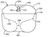
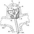
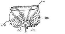
図1A〜図1Cは、図1Aに示されている所定の形状、並びに図1B及び図1Cに示されている2つの個別のインプラント形状を有することができる、例示的編組インプラント100の図である。インプラント100は、図1Bに示されている大きい方の動脈瘤10a、及び図1Cに示されている小さい方の動脈瘤10bを含む、ある範囲のサイズの動脈瘤を処置することができる。インプラント100は、大きい方の動脈瘤10aの処置に貢献することができる第1のインプラント形状(図1B)、及び小さい方の動脈瘤10bの処置に貢献することができる第2のインプラント形状(図1C)を有することができる。インプラント100は、開口端部114及び挟持端部112を有する管状編組110を含み得る。インプラント100は、挟持端部112において編組110に取り付けられた離脱機構150を含み得る。管状編組110は、所定の形状に形成され(図1A)、マイクロカテーテルを介して送達するために折り畳まれ、離脱機構150において送達システムに取り付けられ、2つのインプラント形状の一方又は他方に類似した形状で植え込まれ得る(図1B又は図1C)。 1A-1C are diagrams of an
図1Aを参照すると、管状編組110が所定の形状にあるとき、編組110を3つのセグメント142、144、146に分割する、2つの反転部122、124を含み得る。所定の形状において、編組110は、編組110の開口端部114から一方の反転部122まで延びる外側セグメント142、編組110の挟持端部112から他方の反転部124まで延びる内側セグメント146、及び2つの反転部122、124の間に延びる中間セグメント144を有し得る。管状編組110は、所定の形状にある場合、中心縦軸yを中心にして、実質的に半径方向に対称となり得る(図6A参照)。図1Aは、各セグメント142、144、146の輪郭を示しており、離脱機構150は、機械式インプラント送達システム(例示せず)と共に使用され得る平坦鍵部として示されている。 Referring to FIG. 1A, when the
管状編組110は、編組を外側方向に最初に反転させて、内側セグメント146を、反転部124で中間セグメント144から分離することにより所定の形状に形成することができ、次に、中間セグメント144は、示されている実質的に「S」形状の輪郭を生成する形態の上に成形することができ、最後に、編組110を、やはり外側方向に反転させて、中間セグメント144を別の反転部122で外側セグメント142から分離することができる。必要な場合、編組は、開口端部114において整えることができる。開口端部114は、中間セグメント144を囲むよう位置付けられ得る。開口端部114は、示されているように、編組の高さの中間の第3の区域内に位置付けられ得る。 The
インプラント100が植え込まれたときに動脈瘤頸部の閉塞を最大化するために、中間セグメント144の「S」形状の下側延長部によって画定される頸部開口126を最小化することが有利であり得る。中間セグメント144は、1つ以上の屈曲部132、134を有することができる。この屈曲部132、134は、編組110が図1Cに示されている第2のインプラント形状へと移動するのを容易にするように位置付けられ得、また屈曲部132、134は、第1のインプラント形状及び/又は第2のインプラント形状にある編組110を安定化するように位置付けられ得る。 To maximize occlusion of the aneurysm neck when
管状編組110は、所定の形状に熱硬化することができ、カテーテルを介して送達するよう変形され得、所定の形状に基づきそれが植え込まれる動脈瘤の解剖学的構造によって閉じ込められるインプラント形状に自己拡張することができる、記憶形状材料を含むことができる。 The
図1Bに示されているように、編組110は、第1のインプラント形状にあるとき、動脈瘤壁14aに接触する外層142a、外層142a内に入れ子にされた嚢144a、動脈瘤頸部16aに位置付けられた近位反転部122a、及び動脈瘤壁14aの遠位部分15aの近傍に位置付けられている遠位反転部124aを有し得る。第1のインプラント形状において、編組110の離脱機構150及び挟持端部112は、嚢144a内に懸架され得る。 As shown in FIG. 1B, the
図1A及び図1Bに示されるように、第1のインプラント形状にある管状編組110は、所定の形状に比べて、半径方向に圧縮され、垂直方向に延びることができる。第1のインプラント形状にある外層142aは、所定の形状にある外層142に対応し得、第1のインプラント形状にある近位反転部122aは、所定の形状にある外層142に隣接する反転部122に対応し得、第1のインプラント形状にある嚢144aは、所定の形状にある中間セグメント144に対応し得、第1のインプラント形状にある遠位反転部124aは、所定の形状にある内側セグメント146に隣接する反転部124に対応し得、第1のインプラント形状にある離脱機構150を懸架している内側編組セグメント146aは、所定の形状にある内側セグメント146に対応し得る。第1のインプラント形状では、嚢144aは、所定の形状にある頸部開口部126に対応する頸部開口部126aを有し得る。 As shown in FIGS. 1A and 1B, the
図1Cに示されているように、編組110は、第2のインプラント形状にあるとき、動脈瘤壁14bに接触する外層142b、動脈瘤頸部16bに位置付けられている近位反転部122b、外層142b内に延び、外層142bを押す中間層144b、編組110の開口端部114の近傍に位置付けられた遠位反転部124b、及び中間層144b内に延び、中間層144bを押す内層146bを有し得る。第2のインプラント形状では、編組110の離脱機構150及び挟持端部112は、近位反転部122bの近傍の動脈瘤頸部16bに位置付けられ得る。 As shown in FIG. 1C, the
図1A及び図1Cに示されているように、第2のインプラント形状にある管状編組110は、所定の形状に比べて、半径方向に圧縮され得、所定の形状の中間セグメント144は、折り畳まれることができ、その結果、管状編組110の高さは、所定の形状に比べて、第2のインプラント形状に圧縮される。代替的に、第2のインプラント形状は、動脈瘤の高さよりも著しく小さな直径を有する動脈瘤に、第2のインプラント形状で植え込まれると、所定の形状に比べて、半径方向に圧縮され得、第2のインプラント形状にある編組の高さは、所定の形状にある編組の高さよりも大きくなり得る。 As shown in FIGS. 1A and 1C, the
第2のインプラント形状にある外層142bは、所定の形状にある外層142に対応し得、第2のインプラント形状にある近位反転部122bは、所定の形状にある外層142に隣接する反転部122に対応し得、第2のインプラント形状にある中間層144b及び内層146bは、所定の形状にある中間セグメント144に対応し得、第2のインプラント形状にある遠位反転部124bは、所定の形状にある中間セグメント144における屈曲部134に対応し得、第2のインプラント形状にある内層146bを形成する離脱機構150の近傍の編組110の一部は、所定の形状にある内側セグメント146に対応し得る。 The
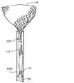
図2A〜図2Hは、編組110がマイクロカテーテル600を出ると、所定の形状まで拡張する編組110を有する、例示的インプラント100の図である。インプラント100は、図1Aに示されているものに類似した所定の形状を有する。図2Aに示すように、編組110は、マイクロカテーテル600及び長さLを通って送達されるようなサイズの圧縮された円周/直径を有する管状編組の単一層に延びる送達形状に成形することができる。図示のインプラント100は、約22mm〜約25mmの長さLを有する。当業者であれば認識及び理解されるように、特定の編組110の長さLは、処置される動脈瘤のサイズ及び形状に基づいて調整することができる。 2A-2H are views of an
マイクロカテーテル600を介した送達中に、離脱機構150は、インプラント100の近位端部において送達システムに取り付けることができ、挟持端部112は、インプラント100の近位端部の近傍に位置付けられ得、開口端部114は、インプラント100の遠位端部を画定することができる。編組110が単一層管に折り畳まれると、マイクロカテーテルを介して送達されるとき、編組110への摩擦力の作用を緩和するのに十分に小さい直径及び十分に短い長さを有する編組110をもたらすことができ、これにより、編組110は、一部の用途において脱被覆状態で送達されることが可能となる。 During delivery via the
図2Bに示されるように、開口端部114は、編組110の他の任意の部分がマイクロカテーテルを出る前に、マイクロカテーテル600を出るように位置付けられ得る。開口端部114がマイクロカテーテル600を出ると、開口端部114は拡張することができる。開口端部114が、示されているように、動脈瘤により拘束されていない場合、開口端部は、所定の形状で、その円周にまで拡張することができる。 As shown in FIG. 2B, the
図2Cに示されているように、編組110の遠位部分は、マイクロカテーテル600を出ると、半径方向への拡張を継続することができる。 As shown in FIG. 2C, the distal portion of the
図2Dに示されているように、編組110は、編組110がマイクロカテーテル600から更に押し出されると、外側セグメント142を画定する反転部122を形成することができる。 As shown in FIG. 2D, the
図2E〜図2Gに示されているように、中間セグメント144の「S」形状は、編組110がマイクロカテーテル600から更に押されると、形成を開始することができる。 As shown in FIGS. 2E-2G, the "S" shape of the
図2Hに示されているように、編組110のすべて又はほぼすべてがマイクロカテーテル600を出ると、動脈瘤によって閉じ込められていない編組110は、図1Aに示されている形状に類似した所定の形状に拡張することができる。所定の形状では、図示されるインプラントの編組110は、約6mm〜約6.5mmの直径及び約5mm〜約5.5mmの高さを有する。 As shown in FIG. 2H, when all or nearly all of the
図2Hに示されている所定の形状にある編組110の最外径と図2Aに示されている送達形状にある編組110の長さとの比は、約0.3〜約0.24である。 The ratio of the outermost diameter of the
図3A〜図3Hは、2つの異なるインプラント形状にある、動脈瘤10内で拡張する、図2A〜図2Hに示されているインプラント100の図である。動脈瘤10は、約6mmの高さ、約6mmの直径、約4mmの頸部直径を有する。動脈瘤10の寸法を、図2Hに示される所定の形状の編組110と比較すると、編組110は、直径がわずかに大きく、高さがわずかに小さく、動脈瘤10の内部は実質的に球形であるが、編組110の外側の寸法はより円筒形である(測定方向については、図6A及び図6B参照)。したがって、インプラント100の編組110が動脈瘤10によって閉じ込められていると、編組110は、半径方向に拘束される。 3A-3H are views of the
図3Aに示されているように、インプラント100は、図2Aに関連して記載されているとおり、マイクロカテーテル600を介して、動脈瘤10へと送達され得る。管状編組110の開口端部114がマイクロカテーテル600を出ると、これは、動脈瘤10内で拡張することができる。示されている動脈瘤10は、幹血管20及び2本の血管枝22a、22bを含む分岐部に位置付けられ、マイクロカテーテル600は、幹血管20を通って送達されているように示されている。インプラントは、湾曲したマイクロカテーテルを介して血管の側壁上の動脈瘤へと送達され得ることが企図されており、このような手技は、本開示の範囲によって包含されることが意図される。 As shown in FIG. 3A, the
図3Bに示されているように、編組110が、マイクロカテーテル600から遠位に更に押されると、編組110は拡張して動脈瘤壁14と並置され、動脈瘤頸部16に形状を合わせることができる。処置される動脈瘤10は、所定の形状にある管状編組110の外径より小さな直径を有することができ、その結果、編組110は、外側に拡張する傾向があり、動脈瘤壁14への力、及び動脈瘤頸部16の外周周りの封止をもたらす。編組110によってもたらされる動脈瘤壁14及び頸部16の外周に対する半径方向の力は、幅広い頸部動脈瘤におけるインプラント100の固定及び動脈瘤10の頸部16の封止の両方を行うのに十分となり得るので、インプラント100は、分岐部において通常発生するなどの、幅広い頸部動脈瘤を処置するのに特に適切となり得る。 As shown in FIG. 3B, when the
図3Cに示されているように、編組110が、マイクロカテーテル600から遠位に更に押されると、近位反転部122aが形成され得る。 As shown in FIG. 3C, when the
図3Dに示されているように、マイクロカテーテル600は、動脈瘤頸部16に近位反転部122aを留置するように操作され得る。近位反転部122aは、動脈瘤10と血管枝22a、22bとの間の境界18(図6Bを参照されたい)を画定する平面の近位側面に留置され得る。いくつかの用途では、編組110の外層142aが動脈瘤頸部16の外周を封止するように、近位反転部122aを平面18から近位方向に十分遠くに配置することが有利であり得るが、インプラント100が血管22a、22b、20に対する閉塞物となるほど近位には配置しないことが有利である。 As shown in FIG. 3D, the
図3Eに示されているように、編組110は、動脈瘤嚢12の内部で拡張することができ、また延びて、編組110の外層142aの内側表面と並置されることができる。外層142aへの並置は、外層142aを動脈瘤壁14に固定する更なる力をもたらすことができる。 As shown in FIG. 3E, the
図3Fに示されているように、動脈瘤10は、図1Bに示されているものに類似した第1のインプラント形状にある管状編組110を収容することが可能な高さを有する。編組110は半径方向に拘束され、動脈瘤の実質的に球形の形状と比べてより円筒の形状を有するので、編組110は、所定の形状よりも高い動脈瘤を収容するよう、所定の形状の高さを越えて延びることができる。図において、所定の形状にあるインプラント100の管状編組110は、動脈瘤の高さよりも約0.5mm〜1mm短い高さを有する、すなわち言い換えると、インプラントは、所定の形状に比べて、第1のインプラント形状において、高さが約10%〜約20%延びている。 As shown in FIG. 3F, the
編組は、図3Gに示されているように近位に引っ張られて、図1Cに例示されている第2のインプラント形状に類似した図3Hに示されている第2のインプラント形状を形成することができるが、図1Cに示されている動脈瘤10bは、図3Hに示されている疑似動脈瘤10よりも小さい(編組110に比べて比例的に)という点で異なる。インプラント100が送達システムから放出される前に、インプラント100は、マイクロカテーテル600内に一部又は完全に後退し、第1のインプラント形状又は第2のインプラント形状のどちらか一方で再位置付けられ得る。更に又は代替的に、マイクロカテーテル600は、遠位に移動されて、図3Hに示されている第2のインプラント形状から図3Fに示されている第1のインプラント形状まで編組110を移動させることができる。一部の用途では、医師は、インプラント100を位置付けながら、第1のインプラント形状又は第2のインプラント形状が、動脈瘤の解剖学的構造及び処置部位により適切であるかどうかを選択することができる。図3A〜図3Hに示されている動脈瘤10及びインプラント100に類似した形状の動脈瘤及びインプラントを伴う処置に関して、この例の実装形態における第1のインプラント形状は、動脈瘤壁14と接触してより大きな表面積の編組110を実現するので、(図3Gに示されている第2のインプラント形状よりもむしろ)図3Fに例示されている第1のインプラント形状にある編組110を成形するのがより有利となり得る。 The braid is pulled proximally as shown in FIG. 3G to form the second implant shape shown in FIG. 3H, which is similar to the second implant shape illustrated in FIG. 1C. However, the
図4A及び図4Bは、図2A〜図2H及び図3A〜図3Hに示されている例示的インプラントの編組110の図であり、これらは、管状編組110が管内で拡張されて、例示的インプラント100の寸法を有するインプラント100が処置に適切であると思われる、動脈瘤直径及び動脈瘤高さの範囲が決まることを示している。図4Aは、5mmの直径を有する管内の編組110を示している。編組110は、第1のインプラント形状にあり、約8mmの高さを有する。したがって、この編組110は、直径が約1mm〜1.5mmだけ、すなわち約17%〜23%だけ、その所定の形状から半径方向に抑制され、高さが約2.5mm〜3mmだけ、すなわち約45%〜60%だけ、垂直方向に拡張されている。 4A and 4B are views of the
図4Bは、4mmの直径を有する管内の編組110を示している。編組110は、第2のインプラント形状にあり、約6mmの高さを有する。したがって、編組は、直径が約2mm〜2.5mmだけ、すなわち約33%〜38%だけ、その所定の形状から半径方向に抑制され、約0.5mm〜1mmだけ、すなわち約10%〜20%だけ、垂直方向に拡張している。 FIG. 4B shows the
したがって、図2Hに関連して図示及び説明されるような所定の形状及び寸法を有するインプラントは、約4mm〜約5mmの直径及び約6mm〜約8mmの高さを有する動脈瘤の処置に適切であり得る。図3Fに示すように、インプラントは、6mmの直径及び6mmの高さを有する動脈瘤を治療するのにも適切であり得る。当業者であれば認識及び理解されるように、所定の形状の管状編組の寸法は、本明細書に記載される原理に従って、本明細書で具体的に概説されていない寸法の範囲内の動脈瘤を処置するように調整することができる。そのように成形されたインプラントのコレクションは、医師に入手可能となり得、医師は、動脈瘤の高さ、直径、頸部直径及び/又はその他の解剖学的特徴に基づいて、コレクションから適切なインプラントを選択することができることが考えられる。 Therefore, implants having a predetermined shape and dimensions as illustrated and described in connection with FIG. 2H are suitable for the treatment of aneurysms having a diameter of about 4 mm to about 5 mm and a height of about 6 mm to about 8 mm. possible. As shown in FIG. 3F, implants may also be suitable for treating aneurysms with a diameter of 6 mm and a height of 6 mm. As will be recognized and understood by those skilled in the art, the dimensions of a tubular braid of a given shape will be arteries within dimensions not specifically outlined herein, according to the principles described herein. It can be adjusted to treat the aneurysm. A collection of such molded implants may be available to the physician, who will determine the appropriate implant from the collection based on the height, diameter, neck diameter and / or other anatomical features of the aneurysm. It is conceivable that you can select.
それぞれが特有の形状をしている管状編組を有するインプラントのコレクションが作成されて、直径及び高さが様々な動脈瘤を処置するためのインプラントのカタログを提供することができる。このカタログは、直径が3mm〜15mmの範囲、及び高さが3mm〜15mmの範囲、又は別の例では、直径が3〜11mmの範囲、及び高さが3〜7mmの範囲の動脈瘤を処置するのに適切なインプラントを含み得る。当業者により認識及び理解されているように、一部の動脈瘤の寸法は、かなり稀であり、カタログは、大きな高さ:直径の比、又は大きな直径:高さ比を有する動脈瘤を処置するためのインプラントを含むことを必要としない。 A collection of implants, each with a uniquely shaped tubular braid, can be created to provide a catalog of implants for treating aneurysms of varying diameters and heights. This catalog treats aneurysms in the range of 3 mm to 15 mm in diameter and 3 mm to 15 mm in height, or in another example, in the range of 3 to 11 mm in diameter and 3 to 7 mm in height. May include suitable implants to do. As recognized and understood by those skilled in the art, the dimensions of some aneurysms are fairly rare and the catalog treats aneurysms with large height: diameter ratios or large diameter: height ratios. It is not necessary to include an implant to do so.
コレクション中の各インプラントは、部分範囲の直径及び部分範囲の高さを有する動脈瘤を処置するのに適切となり得る。例示的カタログは、以下に限定されないが、以下のサイズの部分範囲(直径範囲(mm)、高さ範囲(mm)):(3〜5、3〜5)、(6〜8、4〜5)及び(9〜11、5〜7)のうちの1つ以上の動脈瘤を処置するためのインプラントのリストを含み得る。 Each implant in the collection may be suitable for treating an aneurysm with a partial range diameter and partial range height. An exemplary catalog is not limited to the following, but is a subrange of the following sizes (diameter range (mm), height range (mm)): (3-5, 3-5), (6-8, 4-5). ) And (9-11, 5-7) may include a list of implants for treating one or more aneurysms.
一部の例では、各サイズの部分範囲は、その部分範囲内にある動脈瘤を処置するのに適切となるように特有のサイズ及び形状をしている管状編組を有する単一インプラントによって処置され得る。いくつかの例において、カタログ内の部分範囲は、各々が約10mm、約40mm、及び/又はその間の長さを含む送達長さ(編組が、マイクロカテーテルを介して送達するよう折り畳まれたときの長さ)を有する管状編組を有するインプラントによって表され得る。 In some examples, a subrange of each size is treated with a single implant with a tubular braid that is uniquely sized and shaped to be suitable for treating an aneurysm within that subrange. obtain. In some examples, the subranges in the catalog are delivery lengths, each including a length of about 10 mm, about 40 mm, and / or in between (when the braid is folded to deliver via a microcatheter). Can be represented by an implant with a tubular braid having a length).
当業者によって認識及び理解されるように、動脈瘤の高さ及び直径は、ある程度の誤差範囲を伴って測定される。そのため、所与のインプラントに関するカタログ内に含まれるサイズの部分範囲は、インプラントで処置され得る動脈瘤サイズの一部を表し得、インプラントは、列挙した部分範囲外の動脈瘤を処置することができる。例えば、高さa〜高さbの間の高さ、及び直径x〜直径yの間の範囲の直径を有する動脈瘤を処置するために列挙されているインプラントは、動脈瘤の直径が、この範囲の下限値(約直径x)に近い場合、最大値と列挙されている高さbよりもわずかに高い動脈瘤を処置するのに適切となり得、動脈瘤の高さが、高さ範囲の下限値(約高さa)に近い場合、本インプラントは、直径yよりもわずかに大きな直径を処置するのに適切となり得る。 As recognized and understood by those skilled in the art, the height and diameter of an aneurysm are measured with some margin of error. As such, the size subrange included in the catalog for a given implant may represent part of the aneurysm size that can be treated with the implant, and the implant can treat aneurysms outside the enumerated partial range. .. For example, implants listed for treating an aneurysm having a height between heights a and b, and a diameter in the range between diameters x and y, have an aneurysm diameter of this aneurysm. If it is close to the lower limit of the range (about diameter x), it may be appropriate to treat an aneurysm that is slightly higher than the height b listed as the maximum, and the height of the aneurysm is within the height range. When close to the lower limit (about height a), the implant may be suitable for treating diameters slightly larger than diameter y.
図5A〜図5Dは、様々なサイズの動脈瘤に、第1のインプラント形状又は第2のインプラント形状のどちらか一方で植え込まれた、図1A〜図1Cに示されている例示的インプラント100の図である。図5Aは、大きな動脈瘤10aを示し、図5B及び図5Cは、中程度の動脈瘤10cを示し、図5Dは、小さな動脈瘤10bを示している。インプラント100は、所定の形状にある編組110の直径にほぼ等しい、又はこれより小さな直径を有する、動脈瘤10a、10b、10cに植え込まれるのが有利であり、その結果、編組110は、植え込まれると、動脈瘤壁14に対して外向きの力Fをもたらす。編組110は、1つ以上の外層に対して押圧する内層を有して、力Fに寄与することができる。 5A-5D are
図5Aに示されているように、インプラント100が処置するのに適切となり得る動脈瘤10aの最大サイズは、編組110が第1のインプラント形状でとり得る寸法によって決まり得る。挟持端部112及び離脱機構150は、図1Bに同様に示されているように、動脈瘤壁14aの遠位部分15aの近傍に位置付けられ得る。 As shown in FIG. 5A, the maximum size of the
図5Bに示されているように、インプラント100はまた、第1のインプラント形状の、図5Aに示されている動脈瘤10aよりも小さな、中程度のサイズの動脈瘤10cを処置するのに適切となり得る。第1のインプラント形状にある中程度の動脈瘤10c内に適合させるために、挟持端部112及び離脱機構150は、大きな動脈瘤10aにおける挟持端部112及び離脱機構150の位置に比べて、動脈瘤壁の遠位部分15cから離れて位置付けられ得る。所定の形状(図1Aを参照されたい)では、中間セグメント144は、図5Bに示されている中程度の動脈瘤10cにおいて第1のインプラント形状にある管状編組110を安定化させるための屈曲部134を含むことができる。 As shown in FIG. 5B, the
図5Cに示されているように、インプラント100はまた、第2のインプラント形状にある中程度のサイズの動脈瘤10cを処置するのに適切となり得る。所定の形状にある編組の中間セグメント144(図1Aを参照されたい)は、折り畳まれて、図1Cに関連して記載されているものと類似した中間層144b及び内層146bを形成することができる。一部の用途では、いずれのインプラント形状も、動脈瘤10cを処置するのに有効となり得、医師は、処置中に、好ましい形状を選択することができる。例えば、医師は、近位折り目122aが動脈瘤頸部の外側の近位に配置され得るようにインプラントを延長するために、第1のインプラント形状(図5B)を使用するよう決めることができ、又は医師は、頸部開口部16cを塞栓するように動脈瘤頸部でより多くの層の編組を設けるために、第2のインプラント形状(図5C)を使用するよう決めることができる。 As shown in FIG. 5C, the
図5Dに示されているように、インプラント100が処置するのに適切となり得る動脈瘤10bの最小サイズは、編組110が第2のインプラント形状でとり得る寸法によって決まり得る。開口端部114及び/又は遠位折り目124bは、第2のインプラント形状にある動脈瘤壁の遠位部分15bの近傍で折り畳まれ得る。 As shown in FIG. 5D, the minimum size of the
図6Aは、所定の形状にある例示的インプラント100の高さHI、及び直径D1、D2の測定の図である。所定の形状では、例示的インプラント100の編組110は、垂直軸yを中心に実質的に半径方向に対称となり得、したがって、その直径によってそれぞれが描写可能な実質的に同心円断面を有することができる。図6Aは、反転部122、124の間で測定される、所定の形状にあるインプラント100の高さHI、開口端部114の直径に対応する外側セグメント142の外径D1、及び中間セグメントD2の外径D2を強調している。図6Aは、一例の所定の形状を例示しているに過ぎないが、本明細書に記載されている例示的インプラント100、200、300、400及びそれらの一部の高さ及び直径が、図6Aに示されているものと同様に測定され得ることを理解すべきである。 FIG. 6A is a diagram of measurement of height HI and diameters D1 and D2 of an
図6Bは、動脈瘤10の高さHA、嚢直径DA及び頸部直径DNの測定の図である。動脈瘤10と血管との間の境界を画定する平面18の位置も示されている。 FIG. 6B is a diagram of measurement of height HA, sac diameter DA and neck diameter DN of
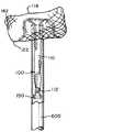
図7Aは、代替的な所定の形状にある管状編組210を有する、例示的インプラント200の図である。図7Bは、インプラント形状にある管状編組210を含む動脈瘤10における例示的インプラント200の図である。管状編組210は、開口端部214及び挟持端部212を有することができる。インプラント200は、挟持端部212において編組210に取り付けられた離脱機構150を含み得る。編組210は、所定の形状で形成され、マイクロカテーテルを介して送達するために折り畳まれ、離脱機構150において送達システムに取り付けられ、インプラント形状で植え込まれ得る。 FIG. 7A is a diagram of an
図7Aに示されているように、管状編組210は、所定の形状にあるとき、編組210を3つのセグメント242、244、248に分割する、2つの反転部222、224を含み得る。所定の形状において、編組210は、編組210の開口端部214から一方の反転部222まで延びる外側セグメント242、編組210の挟持端部212から他方の反転部224まで延びる内側セグメント248、及び2つの反転部222、224の間に延びる中間セグメント244を有し得る。管状編組210は、所定の形状にある場合、中心縦軸yを中心にして、実質的に半径方向に対称となり得る(図6Aを参照されたい)。図7Aは、各セグメント242、244、248の輪郭を示す。 As shown in FIG. 7A, the
図7Aに示されている編組210の所定の形状と図1Aに示されている編組110の所定の形状とを比較すると、外側セグメント142、242及び中間セグメント144、244は、それぞれ互いに類似しており、図7Aに示されている編組210の内側セグメント248は、図1Aに示されている編組110の内側セグメント146よりも長い。図7Aの編組210の挟持端部212は、図1Aに示されている内側セグメント146の近傍の反転部124の近傍よりも、むしろ外側セグメント242に隣接する反転部222の近傍に位置付けられる。図7Aに示されている細長い内側セグメント248は、図7Bに示されるように植え込まれた場合、インプラント200が圧縮に抵抗する助けとなるように位置付けられ得る。 Comparing the predetermined shape of the
図7Aに示されている管状編組210は、いくつかの違いを伴って、図1Aに関連して記載されているものに類似した所定の形状に形成され得る。中間セグメント244は、第2のインプラント形状への編組210の移動を容易にするよう位置付けられた、屈曲部132、134を有する必要はない。図7Aに示されている内側セグメント248は、図1Aに示されているものよりも長く作製され得る。内側セグメント248は、植え込まれると、インプラント200が圧縮された状態になり得る可能性を低減するよう最適化された長さを有するように成形されることができる。 The
図7Aに示されている所定の形状を有する編組210を有するインプラント200は、図2Hに関連して例示及び記載されているものと類似した外径及び高さを含む、所定の形状の外側寸法を有することができる。図7Aに示されている編組210の内側セグメント248は、所定の形状にある編組210の高さにほぼ等しい高さを有することができる。 The
編組210は、マイクロカテーテルを横断するようなサイズにされている、送達形状の単一層管状編組に引き延ばされ得る。送達形状にある編組210の長さは、開口端部214から挟持端部212まで測定され得る。図7Aに示されている所定の形状、並びに図2Hに関連して例示及び記載されている外側寸法を有する編組210は、図2Aに示されている編組110の長さと比べてより長い、送達形状にある長さを有することができる。図7Aに示されている編組210の長さは、送達形状にあるとき、図1Aに示されている所定の形状を有する編組110よりも、所定の形状にある編組110、210のほぼ高さ分だけ長くすることができる。言い換えると、図7Aに示されている所定の形状を有する編組210を有するインプラント200は、所定の形状にあるとき、約6mm〜約6.5mmの外径、及び約5mm〜5.5mmの高さを有することができ、折り畳まれてマイクロカテーテル内に適合する円周、及び約27mm〜30mmである長さを有する単一層管へ延長することができる。所定の形状における最外径と送達形状における長さとの比は、約0.24〜約0.2であることができる。 The
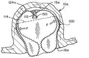
図7Bに示されているように、編組210は、インプラント形状にあるとき、動脈瘤壁14に接触している外層242a、外層242a内に入れ子にされている嚢244a、動脈瘤頸部16に位置付けられている近位反転部222a、及び動脈瘤壁14の遠位部分15の近傍に位置付けられている遠位反転部224aを有し得る。編組210の離脱機構150及び挟持端部212は、近位反転部222aの近傍の動脈瘤頸部16の近傍に位置付けられ得る。離脱機構150及び挟持端部212は、インプラント200が衝突を受ける状態になる可能性を低減するよう位置付けられ得る。 As shown in FIG. 7B, the
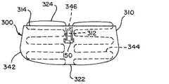
図8Aは、別の代替的な所定の形状にある管状編組310を有する例示的インプラント300の図である。図8Bは、管状編組310がインプラント形状にあるときの例示的インプラント300の図である。管状編組310は、開口端部314及び挟持端部312を有し得、離脱機構150は、挟持端部312において編組310に取り付けることができる。編組310は、所定の形状で形成され、マイクロカテーテルを介して送達するために折り畳まれ、離脱機構150において送達システムに取り付けられ、インプラント形状で植え込まれ得る。 FIG. 8A is a diagram of an
図8Aに示されているように、管状編組310は、所定の形状にあるとき、編組310を3つのセグメント342、344、346に分割する、2つの反転部322、324を含み得る。所定の形状において、編組310は、編組310の開口端部314から一方の反転部322まで延びる外側セグメント342、編組310の挟持端部312から他方の反転部324まで延びる内側セグメント346、及び2つの反転部322、324の間に延びる中間セグメント344を有し得る。管状編組310は、所定の形状にある場合、中心縦軸を中心にして、実質的に半径方向に対称となり得る。図8Aは、各セグメント342、344、346の輪郭を示す。 As shown in FIG. 8A, the
図8Aに示されている編組310の所定の形状と図1Aに示されている編組110の所定の形状とを比較すると、外側セグメント142、342及び内側セグメント146、346は、それぞれ互いに類似しており、図8Aに示されている編組310の中間セグメント344は、図1Aに示されている編組110の中間セグメント144の「S」形状よりも、むしろ起伏パターンを有する。起伏した中間セグメント344は、半径方向に対称となって、ハニカム形状を形成することができる。起伏パターンの中間セグメント344は、植え込まれると、図1Aに示されている「S」形状を有する中間セグメント144によりもたらされ得る力パターンとは異なる、動脈瘤内にインプラント300を固定するよう外側に押圧する力パターンをもたらすことができる。図8Aにおける編組310の挟持端部312は、示されている内側セグメント346に隣接する反転部324の近傍に位置付けられ得る。代替的に、内側セグメント346は、外側セグメント342に隣接する反転部322まで延びて、圧縮耐性カラムをもたらすよう成形され得る。 Comparing the predetermined shape of the
図8Aに示されている管状編組310は、いくつかの違いを伴って、図1Aに関連して記載されているものに類似した所定の形状に形成され得る。中間セグメント344は、「S」形状パターンよりも、むしろ起伏パターンを有するよう形成され得る。中間セグメント344は、第2のインプラント形状への編組310の移動を容易にするように位置付けられた屈曲部を有する必要はない。 The
図8Bに示されているように、編組310は、インプラント形状にあるとき、動脈瘤壁に接触するように成形された外層342a、外層342a内に入れ子にされている起伏状の中間層344aの圧縮延長部、動脈瘤頸部に配置されるよう位置付けられた近位反転部322a、及び動脈瘤壁の遠位部分の近傍に配置されるよう位置付けられた遠位反転部324aを有し得る。編組310の離脱機構150及び挟持端部312は、示されている遠位反転部324aの近傍、近位反転部322aの近傍、又はそれらの間のいずれかの位置のどちらかの、動脈瘤嚢内に位置付けられ得る。離脱機構150及び挟持端部312は、インプラント300が衝撃を受ける状態になる可能性を低減するよう位置付けられ得る。 As shown in FIG. 8B, the
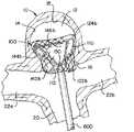
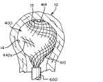
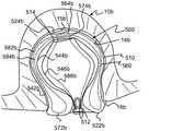
図9Aは、別の代替的な所定の形状にある管状編組410を有する例示的インプラント400の図である。図9Bは、インプラント形状にある、管状編組410を示す例示的インプラント400の図である。管状編組410は、開口端部414及び挟持端部412を有することができる。離脱機構150は、挟持端部412において編組410に取り付けることができる。インプラント400は、所定の形状に形成され、マイクロカテーテルを介して送達するよう折り畳まれ、離脱機構150において送達システムに取り付けられ、インプラント形状で植え込まれ得る。 FIG. 9A is a diagram of an
図9Aに示されているように、管状編組410は、所定の形状にあるとき、編組410を3つのセグメント442、444、446に分割する、2つの反転部422、424を含み得る。所定の形状において、編組410は、編組410の開口端部414から一方の反転部422まで延びる外側セグメント442、編組410の挟持端部412から他方の反転部424まで延びる内側セグメント446、及び2つの反転部422、424の間に延びる中間セグメント444を有し得る。管状編組410は、所定の形状にある場合、中心縦軸yを中心にして、実質的に半径方向に対称となり得る(図6A参照)。図9Aは、各セグメント442、444、446の輪郭を示す。 As shown in FIG. 9A, the
図9Aに示されている編組410の所定の形状と図1Aに示されている編組110の所定の形状とを比較すると、外側セグメント142、442は、互いに類似していてよく、図9Aに示されている編組410の中間セグメント444は、図1Aに示されている「S」形状の中間セグメント144に比べて、それほど顕著ではない「S」形状を有し得、内側セグメント446は、図1Aに示されている内層146に隣接する反転部142の近傍よりも、むしろ外層442に隣接する反転部422の近傍に位置付けられた挟持端部412を有する、円錐形又は「V」形状の輪郭とすることができる。内側セグメント446は、植え込まれると、圧縮耐性カラムを形成するよう再成形され得る。 Comparing the predetermined shape of the
図9Aに例示されている管状編組410は、いくつかの違いを伴って、図1Aに関連して記載されているものに類似した所定の形状に形成され得る。図9Aに示されている中間セグメント444は、図1Aに示されている「S]形状パターン144に比べて、それほど顕著ではない「S」形状パターンを有するよう形成され得る。中間セグメント444は、第2のインプラント形状への編組410の移動を容易にするように位置付けられた屈曲部を有する必要はない。内側セグメント446は、図1Aに示されている内側セグメント146と比べて、図9Aに示されているように、より長い長さを有することができる。内側セグメント446に隣接する反転部424は、図1Aに示されている対応する反転部124に比べて、図9Aに示されているように、より鋭い湾曲部を有し得る。 The
図9Bに示されているように、編組410は、インプラント形状にあるとき、動脈瘤壁に接触するよう成形された外層442a、外層442a内に入れ子にされているチューリップ又は心臓形状の嚢444a、動脈瘤頸部に配置されるよう位置付けられている近位反転部422a、動脈瘤壁の遠位部分の近傍に配置されるよう位置付けられている遠位反転部424a、及び嚢444a内に延びている圧縮耐性カラム446aを有し得る。編組410の離脱機構150及び挟持端部412は、近位反転部422aの近傍の嚢444a内に位置付けられ得る。離脱機構150及び挟持端部412は、インプラント400が衝撃を受ける状態になる可能性を低減するよう位置付けられ得る。 As shown in FIG. 9B, the
図10は、図9Aに示されているものに類似した所定の形状にある、管状編組410を有する例示的インプラント400の図である。 FIG. 10 is a diagram of an
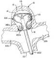
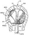
図11A〜図11Eは、図10に示されている例示的インプラント400の図であり、管状編組410が、図9Bに示されているものに類似した疑似動脈瘤10内でインプラント形状まで拡張していることを示している。図11Aに示されているように、開口端部414は、最初にマイクロカテーテルを出て、動脈瘤10内で拡張することができる。図11Bに示されているように、所定の形状にある外層442に対応する編組410の遠位部分は、拡張して、動脈瘤壁14と並置され、インプラント形状にある外層442aを形成することができる。図11Cに示されているように、編組410が、マイクロカテーテル600から遠位に更に押されると、編組410は反転し始めることができる。図11Dに示されているように、近位反転部422aは、チューリップ形状の嚢444aが外層442a内で拡張すると、動脈瘤頸部16に配置され得る。図11Eに例示されているように、編組410は、図9Bに示されているものに類似した動脈瘤10内でインプラント形状に成形され得る。 11A-11E are views of the
本明細書に示され説明されるインプラント100、200、300、400のいずれも、管状編組110、210、310、410と実質的に平行に移動する1つ以上の追加の編組層を含むことができる。複数の層は、互いに同軸に積層され、単一ユニットとして所定の形状に熱処理することができる。いくつかの用途では、多数の層は、動脈瘤頸部において追加の被覆を提供し、動脈瘤内での更なる支持及び適合性を提供することができる。編組の各層は、異なるワイヤ数及び厚さ、編組角度及び直径、並びにワイヤ材料を有する異なる特性によって選択されて、血管造影下での視認性を提供しながら、潜在的に金属被覆率を増加させ、プロファイル(マイクロカテーテルサイズ)を低減し、展開を容易にし、頸部入口チャネルの寸法を低減することができる。 Each of the
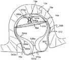
図12Aは、図1Aに示されるものと同様の所定の形状の2つの編組層510、560を含むインプラント500の断面図である。編組層510、560は、離脱機構550が編組層510、560に固定され得る挟持端部512で収縮されている。図示されるように、所定の形状において、編組層510、560の各々は、図1Aに示されているインプラント100に関連して説明されているものと同様に、それぞれの開口端部514、564、第1のセグメント542、582、第1の反転部522、572、第2のセグメント544、584、第1の屈曲部532、592、第2の屈曲部534、594、第2の反転部524、574、及び第3のセグメント546、586を有し得る。2つの編組層510、560の各々について、第3のセグメントは、挟持端部512から第2の反転部524、574まで延び、第2のセグメント544、584は、第2の反転部524、574から第1の反転部まで延びかつ第3のセグメント546、586を少なくとも部分的に囲み、第1のセグメント542、582は、第1の反転部522、572から延びかつ第2のセグメント544、584を少なくとも部分的に囲む。図示されるように、2つの層の各々について、第1のセグメントは、第2のセグメントを部分的にのみ囲む。2つの層の各々の第1の反転部の周りで、層B(560)は、層A(510)内に入れ子になっている。2つの層の各々の第2の反転部の周りで、層Aは、層B内に入れ子になっている。 FIG. 12A is a cross-sectional view of the
図12Bは、マイクロカテーテル600内に位置付けられた編組層510、560を示す。編組層510、560は、示されるように、内層560(層B)及び外層510(層A)と同軸管として位置付けられることができる。ベンチトップ試験では、2つの編組層が、同じ総ワイヤ数を有する単一層編組と比較して、より小さな編組外周長(C)になり得ることが実証されている。単一層管状編組110、210、310、410を含むインプラント100、200、300、400は、好ましくは72のワイヤ数又は96のワイヤ数を有する。同じ合計ワイヤ数を有すると、2つの層510、560を有するインプラント500は、送達システムへの折り畳み時に編組プロファイルサイズを低減することができる。それは、トラック力及びマイクロカテーテルサイズも低減することができ、これは、より困難な遠位の脈管構造への操縦能力を促進することができる。同じ送達管サイズでは、編組の2つの層510、560は、そのサイズに適合することができる総ワイヤ数を増加させることができる。追加されたワイヤ数は、動脈瘤の頸部の気孔率を減少させて、治癒を促進し、破裂した動脈瘤をより迅速に処置するために、頸部での流れの迂回及び血栓形成を促進することができる。追加されたワイヤは、異なる解剖学的位置における、より大きな動脈瘤内のインプラントの展開も容易にすることができる。 FIG. 12B shows the braided layers 510 and 560 positioned within the
図12Cは、図1Bに示されるインプラント形状と同様の第1のインプラント形状の、より大きな動脈瘤10a内に植え込まれたインプラント500を示す。より大きな動脈瘤10aは、頸部開口部16aである入口を有する第1の実質的に球状の空洞を画定する。図示されるように、第1のインプラント形状では、2つの層の各々は、所定の形状の第1のセグメントに対応する外層と、所定の形状の第1の反転部に対応する近位反転部と、を有する。図示されるように、層A510の外層542aは、より大きな動脈瘤10の空洞壁14aに接触するように位置付けられ、層B560の外層582aは、層A510の外層542aと並置され、2つの層510、560の各々の近位反転部522a、572aは、より大きな動脈瘤10aへの入口16a付近に位置付けられる。図示されるように、管状編組の2つの層510、560の各々は、所定の形状の第2のセグメント544、584に対応する嚢544a、584aを備える。層B560の嚢584aは、より大きな動脈瘤10aの空洞壁の一部分と並置されるように位置付けられる。層A510の嚢544aは、層B560の嚢584a内に収容されている。 FIG. 12C shows an
2つの層510、560は、潜在的に、より強力な単一層編組のように機能するように一緒に押すことができ、これは、いくつかの用途では、角度が付けられた動脈瘤内でのインプラントの展開を容易にすることができる。動脈瘤内に展開されると、2つの層の各々の外側セグメントは動脈瘤壁に対して外向きに拡張して、動脈瘤壁に対して編組を安定化させる。単一の編組層を有するインプラントと、2つ以上の編組層を有するインプラントと、を比較すると、2つのインプラントは、同様のサイズ及び形状にされた所定の形状を有しており、単一の編組層は、動脈瘤頸部付近での反転を促進するためにカテーテルの遠位端部の再位置付けを必要とする場合があるのに対し、2つ以上の編組層を有するインプラントは、カテーテルの遠位端部の再位置付けを必要とせずに、挟持端部の遠位移動によって動脈瘤頸部付近で反転され得る。追加されたワイヤ数は、動脈瘤ドームでの順応性及び支持を増加させることもできる。 The two
2つの層は、外側の編組に対して内側の編組を支持し、圧縮に抵抗するために、慢性的な外向きの力を潜在的に増加させることもできる。図5Aに示すように、単一層編組110は、動脈瘤壁14aに対して半径方向力Fを提供することができる。同様に、図12Cに図示されているような編組の2つの層510、560は、他のすべてが等しい場合に、単一層編組110よりも大きな動脈瘤壁14aに対する半径方向の力Fを提供することができる。言い換えれば、インプラント100が、所定の形状に形成された単一層編組110を有し、総ワイヤ数を有し、各ワイヤがワイヤ円周を有し、動脈瘤10aを処置するために使用され、またインプラント500が、編組の2つの層510、560を有し、単一層編組110の総ワイヤ数と等しい総ワイヤ数を有し、平均ワイヤ周長が単一層編組110のワイヤにほぼ等しく、同じ動脈瘤又は実質的に同じサイズの動脈瘤10aを治療するために使用されるとすると、2つの層510、560は、単一層110と比較して、動脈瘤壁14aに対して、より大きな半径方向の力Fを提供することができる。 The two layers can also potentially increase chronic outward forces to support the inner braid against the outer braid and resist compression. As shown in FIG. 5A, the
図12Dは、図1Cに示されるインプラント形状と同様の第2のインプラント形状で、より小さな動脈瘤10b内に植え込まれたインプラント500を示す。より小さな動脈瘤10bは、頸部開口部16bである入口を有する第2の実質的に球状の空洞を画定する。図示されるように、第2のインプラント形状において、2つの層510、560の各々は、所定の形状の第1のセグメント542、582に対応する外層542b、582bと、所定の形状の第1の反転部522、572に対応する近位反転部522b、572bと、を有する。層A510の外層542bは、より小さな動脈瘤10bの空洞壁14bに接触する。層B560の外層582bは、層A510の外層542bと並置される。2つの層の各々の近位反転部522b、572bは、第2の実質的に球状の空洞10bへの入口16b付近に配置される。管状編組の2つの層の各々は、所定の形状の第2のセグメント544、584に対応する中間層544b、584b及び内層546b、586b、並びに中間層と内層とを分離する折り目524b、564bを有する。層B560の内層586bは、層B560の外層582bと並置される層B560の中間層584bと並置される層A510の中間層544bと並置される層A510の内層546bと並置される。 FIG. 12D shows the
図12Aに示す所定の形状では、管状編組の2つの層510、560の各々は、それぞれの第2のセグメント544、584内に位置付けられた1つ以上の屈曲部532、534、592、594を含む。図12Dに示す第2のインプラント形状では、2つの層510、560の各々について、中間層544b、584bと内層546b、586bとを分離する折り目524b、574bは、所定の形状の第2のセグメントの屈曲部のうちの1つに対応する。 In the predetermined shape shown in FIG. 12A, each of the two
図12Cに示す第1のインプラント形状では、挟持端部512は、層A510及び層B560の嚢544a、584a内に懸架される。図12Dに示す第2のインプラント形状では、挟持端部512は、層A510及び層B560の近位反転部522a、572aによって囲まれている。 In the first implant shape shown in FIG. 12C, the pinching
図12Cに示す第1のインプラント形状では、2つの層510、560は、嚢544a、584aを囲む開口端部514、564を形成する。図12Dに示す第2のインプラント形状では、2つの層510、560の各々について、開口端部514、564は、折り目524b、574bを囲む。 In the first implant shape shown in FIG. 12C, the two
インプラント500は、図3A〜図3Gに示すものと同様の工程に従って送達及び植え込むことができる。インプラント500は、挟持端部の操作及びカテーテルの遠位端部の位置付けのみにより、動脈瘤/球状空洞内に位置付けられることができる。カテーテルの遠位端部は、動脈瘤頸部/空洞入口の近くに位置付けられることができる。インプラント500の挟持端部512は、カテーテル600の少なくとも一部を通してインプラント500を押すように、遠位に押すことができる。層A510の外層542a、542bは、動脈瘤壁14と並置されることができる。層B560の外層582a、582bは、層A510の外層542a、542bと並置されることができる。少なくとも第1のインプラント形状について、嚢584aは、層A及び層Bの外層542a、582aによって少なくとも部分的に囲まれた層B560から形成することができ、嚢544aは、層A及び層Bの外層によって少なくとも部分的に囲まれ、層Bの嚢内に収容された、層A510から形成することができる。挟持端部は係合解除することができ、一方、2つの層510、560の各々は、それらのそれぞれの嚢544a、584aを保持して、インプラント500を第1のインプラント形状に植え込まれたままにすることができる。少なくとも第2のインプラント形状について、第2のインプラント形状の2つの層510、560の各々の第2のセグメント544、584は、折り畳まれて、折り目524b、574bによって分離された内層546b、586b及び中間層544b、584bを形成することができ、それにより層B560の内層586bは、層B560の外層582bと並置される層B560の中間層584bと並置される層A510の中間層544bと並置される層A510の内層546bと並置される。
図1A〜図1Cに図示されたインプラント100と同様の2つのインプラント形状を有することにより、図12A〜図12Dに図示されたインプラント500は、約4mmである第1の直径及び約6mmである第1の高さを有する第1の動脈瘤、約5mmである第2の直径及び約8mmである第2の高さを有する第2の動脈瘤、並びに約6mmである第3の直径及び約6mmである第3の高さを有する第3の動脈瘤を処置するのに適切であり得る(医療デバイスのための適切な管轄要件により)。また、図1A〜図1Cに図示されたインプラント100と同様の2つのインプラント形状を有することにより、図12A〜図12Dに図示されたインプラント500は、動脈瘤のサイズの連続体内の複数の動脈瘤を処置するのに好適であり得、その連続体は、約4mm〜約5mmの直径、及び約6mm〜約8mmの高さによって境界をつけられ、かつこれらを含む。 By having two implant shapes similar to the
図13は、所定の形状の2つの編組層710、760を有する別のインプラント700の断面を示す。インプラント700は、図1A及び図12Aに示されるインプラント100、500と同様に、所定の形状700に形成される。図13に示すインプラント700は、主に、頸部チャネル526、716の領域において、図12Aに示すインプラント500とは異なる。 FIG. 13 shows a cross section of another
2つ以上の編組層を含むことにより、ニチノール−白金ワイヤ織り編組で作製されたデバイスの内側頸部チャネルサイズを潜在的に減少させることができる。換言すれば、所定の形状を達成する実質的に同一のプロセスの場合、2つの層510、710、560、760を有するインプラント500、700の頸部チャネル開口部526、726は、単一の編組層110を有するインプラント100の頸部チャネル開口部126よりも小さくてもよい。同様に、植え込まれると、図12Cに示す頸部チャネル開口部526aは、図1Bに示す頸部チャネル開口部126aよりも小さくすることができ、図13の頸部チャネル726に対しては更に小さくすることができる。大きな開口部を有する頸部チャネルは、動脈瘤頸部に一定の血流を到達させ、治癒を遅くし得る。編組に加えられた白金ワイヤは、一般に、血管造影下でそれぞれのインプラントの編組部分を視認可能にする。しかしながら、白金ワイヤは、熱処理後にニチノールワイヤほどその形状を保持しないため、展開時には、ニチノール−白金編組デバイスは、全ニチノール編組(ニチノール−白金編組及び全ニチノール編組は実質的に同一の所定の形状を有する)と比較して、より大きな頸部チャネル開口部を有することが予想される。 The inclusion of two or more braided layers can potentially reduce the medial neck channel size of devices made from nitinol-platinum wire woven braids. In other words, in the case of substantially the same process to achieve a given shape, the
特定のニーズ及び編組特性に応じて、2つ以上の編組層を含むインプラントでは、全ニチノール編組をニチノール−白金編組と組み合わせて使用することができ、それにより、ニチノール−白金編組は編組の編組部分の可視化を容易にし、全ニチノール編組は編組層を所定の形状に移動させることを容易にする。全ニチノール編組を内側の編組又は外側の編組のいずれかとして使用して、ニチノール−白金編組で製作した場合、内側のチャンネルサイズを低減することができる。図12Aは、全ニチノール編組が送達中に外側に位置付けられた層A510と、ニチノール−白金編組が送達中に内側に位置付けられた層B560と、を有するインプラント500を示す。展開されると、ニチノール編組510は、小さな頸部内側チャネル526aを作り出すことができ、ニチノール−白金編組560のより大きなチャネルを覆い得る。図13は、層B760として位置付けられた全ニチノール編組と、層A710として位置付けられたニチノール−白金編組と、を有するインプラント700を示す。展開されると、ニチノール編組760は、ニチノール−白金編組710上でシンチダウンし、図1Aに示すように、ニチノール−白金編組110のみを有する頸部チャネル126の開口部よりも小さな二重層頸部チャネル726を作り出すことができる。 For implants containing two or more braid layers, depending on specific needs and braid characteristics, the entire nitinol braid can be used in combination with the nitinol-platinum braid, whereby the nitinol-platinum braid is a braid portion of the braid. The whole nitinol braid makes it easy to move the braid layer into a given shape. When the entire Nitinol braid is used as either the inner braid or the outer braid and made from the Nitinol-platinum braid, the inner channel size can be reduced. FIG. 12A shows an
図13を参照すると、編組層710、760は、離脱機構750が編組層710、760に固定され得る、挟持端部712で収縮されている。図示されるように、所定の形状において、編組層710、760の各々は、図1Aに図示されたインプラント100に関連して及び図12Aに図示されたインプラント500に関連して説明されたのと同様に、それぞれの開口端部714、764、第1のセグメント742、782、第1の反転部722、772、第2のセグメント744、784、第1の屈曲部732、792、第2の屈曲部734、794、第2の反転部724、774、及び第3のセグメント746、786を有し得る。2つの編組層710、760の各々について、第3のセグメント746、786は、挟持端部712から第2の反転部724、774まで延び、第2のセグメント744、784は、第2の反転部724、774から第1の反転部まで延びかつ第3のセグメント746、786を少なくとも部分的に囲み、第1のセグメント742、782は、第1の反転部722、772から延びかつ第2のセグメント744、784を少なくとも部分的に囲む。図示されるように、2つの層710、760の各々について、第1のセグメント742、782は、それぞれの第2のセグメント744、784を部分的にのみ囲む。2つの層の各々の第1の反転部722、772について、層B760は、層A710内に入れ子になっている。2つの層の各々の第2の反転部724、774について、層A710は、層B760内に入れ子になっている。 With reference to FIG. 13, the braided layers 710, 760 are contracted at the sandwiching
インプラント700は、図12Bに示されるものと同様のカテーテル600を介して送達することができる。インプラントは、図3A〜図3Gに図示し、図12A〜図12Dに関連して説明したのと同様の工程を介して位置付けることができる。インプラント700は、図12C及び図12Dに図示するのと同様の2つの個別のインプラン形状に植え込むことができる。
図14は、所定の形状の2つの編組層810、860を有する別のインプラント800の断面を示す。インプラント800は、図7Aに示されるものと同様の所定の形状を有しており、相違点は、図7Aに示されるインプラントが1つの管状編組を有するのに対し、図14に示されるインプラント800は、2つの管状編組層を有することである。図14に示すインプラント800は更に、図12Aに示されるものと同様の所定の形状を有し、相違点は、図14に示されるインプラント800が、編組810の内側セグメント846、886から形成された二重層の圧縮耐性ポストを含むことである。 FIG. 14 shows a cross section of another
編組層810、860は、離脱機構850が編組層810、860に固定され得る、挟持端部812で収縮される。図示されるように、所定の形状において、編組層810、860の各々は、図1Aに示されるインプラント100に関連して及び図12Aに示されるインプラント500に関連して説明したものと同様に、それぞれの開口端部814、864、第1のセグメント842、882、第1の反転部822、872、第2のセグメント844、884、第1の屈曲部832、892、第2の屈曲部834、894、第2の反転部824、874、及び第3のセグメント846、886を有することができる。2つの編組層810、860の各々について、第3のセグメント846、886は、挟持端部812から第2の反転部824、874まで延び、第2のセグメント844、884は、第2の反転部824、874から第1の反転部まで延びかつ第3のセグメント846、886を少なくとも部分的に囲み、第1のセグメント842、882は、第1の反転部822、872から延びかつ第2のセグメント844、884を少なくとも部分的に囲む。図示されるように、2つの層810、860の各々について、第1のセグメント842、882は、それぞれの第2のセグメント844、884を部分的にのみ囲む。2つの層の各々の第1の反転部822、872について、層B860は、層A810内に入れ子になっている。2つの層の各々の第2の反転部824、874について、層A810は、層B860内に入れ子になっている。 The braided layers 810, 860 are contracted at the sandwiching
管状編組の2つの層810、860は、編組層810、860が動脈瘤の内部などの実質的に球形の空洞によって拘束されているときに、図14に示す所定の形状に基づいてインプラント形状で安定化することができる。インプラント形状において、層A810は、実質的に球状の空洞/動脈瘤の空洞壁に並置された第1のセグメント842に対応する外層を有し、層B760は、層A810の外層に並置された第1のセグメント882に対応する外層を有し、層B860は、層B860の外層に並置された中間セグメント884に対応する内嚢を有し、層A810は、層B860の内嚢内に位置付けられた中間セグメント844に対応する内嚢を有し、2つの層810、860の各々について、第1の反転部822、872に対応する近位反転部は、実質的に球状の空洞/動脈瘤頸部への入口付近に位置付けられ、2つの層810、860の各々について、第2の反転部824、874に対応する遠位反転部は、空洞壁の遠位部分付近に位置付けられ、2つの層810、860の各々は、第3のセグメント846、886に対応するポストを備え、そのポストは、内嚢内で遠位反転部と近位反転部との間の長さの大部分に沿って中央に延び、それによりB層のポストは、A層のポスト内に位置付けられている。 The two
インプラント800は、図12A〜図12Cに示したインプラント500の第1のインプラント形状に関連して説明されたのと同様に送達され、植え込まれ得るが、それらの違いは、図15に示されたインプラント800の挟持端部812は、動脈瘤頸部の近くに位置付けられることができ、第3のセグメント846に対応する層Aの管状セグメントは、層A810の嚢及び層B860の嚢内で延びて、挟持端部812で終端することができ、第3のセグメント886に対応する層B860の管状セグメントは、層A810の管状セグメント内で延びて、挟持端部812で終端することができるということである。
図示していないが、図8A〜図8B、図9A〜図9B、図10、及び図11A〜図11Eに図示されるインプラント300、400は、代替的に、図12A〜図12D、図13、及び図14に関連して図示及び説明した原理に従って、2つ以上の編組層を含むことができる。更に、各インプラント100、200、300、400、500、700、800は、合計で2つ、3つ、4つ、又は5つの編組層を含むことができる。 Although not shown, the
例示的なインプラント100、200、300、400、500、700の管状編組110、210、310、410、510、560、710、760、810、860は、所定の形状に熱硬化することができ、カテーテルを介して送達するために変形することができ、所定の形状に基づき、植え込まれる動脈瘤の解剖学的構造によって閉じ込められるインプラント形状に自己拡張することができる、形状記憶材料を含むことができる。管状編組は、白金ワイヤストランド、マーカ、又はその他の放射線不透過性機構を更に含むことができる。 The
本明細書に記載の例示的インプラント100、200、300、400、500、700、800は、半径方向外向きの力に依存して、動脈瘤の嚢内にインプラントを固定することができる。この目的のために、編組(複数可)110、210、310、410、510、560、710、760は、動脈瘤内に植え込まれたときに編組が半径方向に収縮するように、その高さ(複数の編組層を有するインプラントの場合は最遠位層と最近位層との間)よりも大きな直径(複数の編組層を有するインプラントの場合は半径方向の最外編組の直径)を有する所定の形状に成形することができる。それぞれの所定の形状の編組110、210、310、410、510、560、710、760、810、860の直径対高さの比は、多くの既知のサイズ及び形状の動脈瘤を処置するために、2:1〜1:3の範囲内にすることができる。 The
本明細書で任意の数値又は数値の範囲について用いる「約」又は「およそ」という用語は、構成要素の部分又は構成要素の集合が、本明細書において説明されるその意図された目的に沿って機能することを可能とする、適切な寸法の許容誤差を示すものである。より具体的には、「約」又は「およそ」とは、列挙された値の±20%の値の範囲を指し得、例えば「約90%」は、71%〜99%の値の範囲を指し得る。 The term "about" or "approximately" as used herein for any number or range of numbers means that a component or set of components is in line with its intended purpose as described herein. It indicates an appropriate dimensional tolerance that allows it to function. More specifically, "about" or "approximately" can refer to a range of ± 20% of the listed values, for example "about 90%" can range from 71% to 99%. Can point.
本明細書に含まれる記述は、本発明の実施形態の例であり、本発明の範囲を何ら制限するものではない。本明細書に記載されるように、本発明は、代替的材料、代替的な幾何学的形状、代替的な離脱機構、代替的な送達システム、編組を所定の形状に形成するための代替的手段、代替的な処置方法、代替的な数の編組層などを含む、インプラントの多くの変形及び修正を企図する。本発明が関連する当業者には明らかなこれらの修正は、以下の特許請求の範囲内であることが意図される。 The description contained herein is an example of an embodiment of the present invention and does not limit the scope of the present invention in any way. As described herein, the present invention provides alternative materials, alternative geometric shapes, alternative detachment mechanisms, alternative delivery systems, alternatives for forming braids into a given shape. Many modifications and modifications of the implant are intended, including means, alternative treatment methods, alternative numbers of braided layers, and the like. These modifications, which are apparent to those skilled in the art to which the present invention is associated, are intended to be within the scope of the following claims.
〔実施の態様〕
(1) 挟持端部で一緒に収縮した管状編組の2つの層(層A及び層B)を備え、前記2つの層が所定の形状を備え、前記所定の形状では、前記2つの層の各々が、それぞれ第1の反転部及び第2の反転部並びに第1のセグメント、第2のセグメント、及び第3のセグメントを備え、それにより、前記第3のセグメントが前記挟持端部から前記第2の反転部まで延び、前記第2のセグメントが前記第2の反転部から前記第1の反転部まで延びかつ前記第3のセグメントを少なくとも部分的に囲み、前記第1のセグメントが前記第1の反転部から延びかつ前記第2のセグメントを少なくとも部分的に囲む、
インプラント。
(2) 前記2つの層の各々について、前記第1のセグメントのみが前記第2のセグメントを部分的に囲む、実施態様1に記載のインプラント。
(3) 前記2つの編組層のうちの一方が、いかなる放射線不透過性ワイヤも備えず、前記2つの編組層のうちの他方が、放射線不透過性ワイヤを備える、実施態様1に記載のインプラント。
(4) 前記管状編組の2つの層が、第1の実質的に球状の空洞によって拘束されたときに、前記所定の形状に基づいて第1のインプラント形状で安定であり、前記管状編組の2つの層が、第2の実質的に球状の空洞によって拘束されたときに、前記所定の形状に基づいて第2のインプラント形状で安定であり、
前記第1のインプラント形状及び前記第2のインプラント形状の各々において、前記2つの層の各々が、前記所定の形状の前記第1のセグメントに対応する外層と、前記所定の形状の前記第1の反転部に対応する近位反転部と、を備え、
前記第1のインプラント形状において、前記層Aの外層が、前記第1の実質的に球状の空洞の空洞壁に接触するように位置付けられ、前記層Bの外層が、前記層Aの外層と並置され、前記2つの層の各々の前記近位反転部が、前記第1の実質的に球状の空洞への入口付近に配置されるように位置付けられ、
前記第1のインプラント形状において、前記管状編組の2つの層の各々が、前記所定の形状の前記第2のセグメントに対応する嚢を備え、前記層Bの嚢が、前記第1の実質的に球状の空洞の空洞壁の一部分と並置されるように位置付けられ、前記層Aの嚢が前記層Bの嚢内に収容され、
前記第2のインプラント形状において、前記層Aの外層が、前記第2の実質的に球状の空洞の空洞壁に接触するように位置付けられ、前記層Bの外層が、前記層Aの外層と並置されるように位置付けられ、前記2つの層の各々の前記近位反転部が、前記第2の実質的に球状の空洞への入口付近に配置されるように位置付けられ、
前記第2のインプラント形状において、前記管状編組の2つの層の各々が、前記所定の形状の前記第2のセグメントに対応する中間層及び内層と、前記中間層と前記内層とを分離する折り目と、を備え、それにより、前記層Bの内層が、前記層Bの外層と並置される前記層Bの中間層と並置される前記層Aの中間層と並置される前記層Aの内層と並置される、
実施態様1に記載のインプラント。
(5) 前記所定の形状において、前記管状編組の2つの層の各々が、前記第2のセグメント内に位置付けられた屈曲部を備え、
前記第2のインプラント形状において、前記2つの層の各々について、前記中間層と前記内層とを分離する前記折り目が、前記所定の形状の前記第2のセグメントの前記屈曲部に対応する、
実施態様4に記載のインプラント。[Implementation mode]
(1) Two layers (layer A and layer B) of a tubular braid that are contracted together at the sandwiching end are provided, the two layers have a predetermined shape, and in the predetermined shape, each of the two layers. Includes a first inversion and a second inversion and a first segment, a second segment, and a third segment, respectively, whereby the third segment is from the pinching end to the second. The second segment extends from the second inversion to the first inversion and at least partially surrounds the third segment, the first segment of which is the first. Extending from the inversion and at least partially surrounding the second segment,
Implant.
(2) The implant according to embodiment 1, wherein for each of the two layers, only the first segment partially surrounds the second segment.
(3) The implant according to embodiment 1, wherein one of the two braided layers does not have any radiation permeable wire and the other of the two braided layers has a radiation opaque wire. ..
(4) When the two layers of the tubular braid are constrained by the first substantially spherical cavity, they are stable in the first implant shape based on the predetermined shape and the 2 of the tubular braid. The two layers are stable in the second implant shape based on the predetermined shape when constrained by the second substantially spherical cavity.
In each of the first implant shape and the second implant shape, each of the two layers has an outer layer corresponding to the first segment of the predetermined shape and the first of the predetermined shape. Proximal inversion part corresponding to the inversion part, and
In the first implant shape, the outer layer of the layer A is positioned so as to contact the cavity wall of the first substantially spherical cavity, and the outer layer of the layer B is juxtaposed with the outer layer of the layer A. And the proximal inversion of each of the two layers is positioned so that it is located near the entrance to the first substantially spherical cavity.
In the first implant shape, each of the two layers of the tubular braid comprises a sac corresponding to the second segment of the predetermined shape, and the sac of the layer B is the first substantially. Positioned to juxtapose a portion of the cavity wall of the spherical cavity, the layer A sac is housed within the layer B sac.
In the second implant shape, the outer layer of the layer A is positioned so as to contact the cavity wall of the second substantially spherical cavity, and the outer layer of the layer B is juxtaposed with the outer layer of the layer A. The proximal inversion of each of the two layers is positioned so that it is located near the entrance to the second substantially spherical cavity.
In the second implant shape, each of the two layers of the tubular braid has an intermediate layer and an inner layer corresponding to the second segment of the predetermined shape, and a crease that separates the intermediate layer and the inner layer. , Thus the inner layer of the layer B is juxtaposed with the intermediate layer of the layer A juxtaposed with the intermediate layer of the layer B juxtaposed with the outer layer of the layer B and juxtaposed with the inner layer of the layer A juxtaposed with the intermediate layer of the layer A. Be done,
The implant according to embodiment 1.
(5) In the predetermined shape, each of the two layers of the tubular braid comprises a bend located within the second segment.
In the second implant shape, for each of the two layers, the crease that separates the intermediate layer and the inner layer corresponds to the bend in the second segment of the predetermined shape.
The implant according to embodiment 4.
(6) 前記第1のインプラント形状において、前記挟持端部が、層A及び層Bの前記嚢内に懸架され、
前記第2のインプラント形状において、前記挟持端部が、層A及び層Bの前記近位反転部によって囲まれている、
実施態様4に記載のインプラント。
(7) 前記第1のインプラント形状において、前記2つの層が、前記嚢を囲む開口端部を形成し、
前記第2のインプラント形状において、前記開口端部が前記折り目を囲む、
実施態様4に記載のインプラント。
(8) 前記管状編組の2つの層が、実質的に球状の空洞によって拘束されたときに、前記所定の形状に基づいてインプラント形状で安定であり、
前記インプラント形状において、層Aが、前記実質的に球状の空洞の空洞壁に並置された外層を備え、層Bが、前記層Aの外層に並置された外層を備え、層Bが、前記層Bの外層に並置された内嚢を備え、層Aが、層Bの前記内嚢内に位置付けられた内嚢を備え、前記2つの層の各々について、前記第1の反転部に対応する近位反転部が、前記実質的に球状の空洞の入口付近に位置付けられ、前記2つの層の各々について、前記第2の反転部に対応する遠位反転部が、前記空洞壁の遠位部分付近に位置付けられ、前記2つの層の各々が、前記第3のセグメントに対応するポストを備え、前記ポストが、前記内嚢内で中央に、前記遠位反転部と前記近位反転部との間の長さの大部分に沿って延び、前記層Bのポストが前記層Aのポスト内に位置付けられている、
実施態様1に記載のインプラント。
(9) 前記インプラントが、約4mmである第1の直径及び約6mmである第1の高さを有する第1の動脈瘤、約5mmである第2の直径及び約8mmである第2の高さを有する第2の動脈瘤、並びに約6mmである第3の直径及び約6mmである第3の高さを有する第3の動脈瘤を処置するように構成されている、
実施態様1に記載のインプラント。
(10) 前記インプラントが、動脈瘤サイズの連続体内の複数の動脈瘤を処置するように構成され、前記連続体が、約4mm〜約5mmの直径及び約6mm〜約8mmの高さによって境界をつけられ、かつこれらを含む、
実施態様1に記載のインプラント。(6) In the first implant shape, the sandwiching end is suspended in the sac of layer A and layer B.
In the second implant shape, the pinching ends are surrounded by the proximal inversions of layers A and B.
The implant according to embodiment 4.
(7) In the first implant shape, the two layers form an open end surrounding the sac.
In the second implant shape, the open end surrounds the crease.
The implant according to embodiment 4.
(8) The two layers of the tubular braid are stable in implant shape based on the predetermined shape when constrained by a substantially spherical cavity.
In the implant shape, layer A comprises an outer layer juxtaposed to the cavity wall of the substantially spherical cavity, layer B comprises an outer layer juxtaposed to the outer layer of layer A, and layer B comprises the layer. With an inner sac juxtaposed to the outer layer of B, layer A has an inner sac located within said inner sac of layer B, and for each of the two layers proximal to the first reversal. The inversion is located near the entrance of the substantially spherical cavity, and for each of the two layers, the distal inversion corresponding to the second inversion is near the distal portion of the cavity wall. Positioned, each of the two layers comprises a post corresponding to the third segment, with the post centered within the inner capsule and the length between the distal inversion and the proximal inversion. The post of the layer B is located within the post of the layer A, extending along most of the dimensions.
The implant according to embodiment 1.
(9) The implant has a first aneurysm having a first diameter of about 4 mm and a first height of about 6 mm, a second diameter of about 5 mm and a second height of about 8 mm. It is configured to treat a second aneurysm with a ridge, and a third aneurysm with a third diameter of about 6 mm and a third height of about 6 mm.
The implant according to embodiment 1.
(10) The implant is configured to treat a plurality of aneurysms in an aneurysm-sized continuum, the continuum being bounded by a diameter of about 4 mm to about 5 mm and a height of about 6 mm to about 8 mm. Attached and includes these,
The implant according to embodiment 1.
(11) カテーテルの遠位端部を動脈瘤の動脈瘤頸部に近接して位置付けることと、
管状編組の2つの層(層A及び層B)を備えるインプラントの挟持端部を、前記カテーテルの少なくとも一部分を通して遠位に押すことと、
層Aの外層を前記動脈瘤壁に並置することと、
層Bの外層を前記層Aの外層に並置することと、
層A及び層Bの前記外層によって少なくとも部分的に囲まれた層Bの嚢を形成することと、
層A及び層Bの前記外層によって少なくとも部分的に囲まれ、層Bの嚢内に収容された、層Aの嚢を形成することと、
を含む、方法。
(12) 前記インプラントを、前記挟持端部の操作のみにより、及び前記カテーテルの前記遠位端部の位置付けにより、前記動脈瘤内に位置付けること、を更に含む、
実施態様11に記載の方法。
(13) 層Aが層Bによって囲まれるように、前記2つの層の各々を、それぞれ単一層の管状形状を形成するように延長することと、
ワイヤ数が前記2つの層の前記ワイヤ数の合計に等しく、ワイヤ周長が前記2つの層の前記ワイヤの平均ワイヤ周長にほぼ等しい、完全に折り畳まれた単一層管状編組の外周長よりも小さな外周長を構成するように前記2つの層を折り畳むことと、
を更に含む、実施態様11に記載の方法。
(14) 前記外層Aを、前記動脈瘤と実質的に同一のサイズを有する第2の動脈瘤の動脈瘤壁に単一層編組によって加えられる半径方向の力よりも大きな半径方向の力で前記動脈瘤壁に押圧することを更に含み、前記2つの層が、前記単一層編組の前記ワイヤ数にほぼ等しい合計ワイヤ数、前記単一層編組の前記平均ワイヤ周長にほぼ等しい平均ワイヤ周長、及び前記単一層編組と実質的に同一のプロセスによって形成された所定の形状を有する、
実施態様11に記載の方法。
(15) 実質的に同一のサイズを有する第2の動脈瘤内に植え込まれた単一層編組と比較して、前記動脈瘤頸部にわたって、前記編組の2つの層が、小さい入口チャネル、減少した気孔率、及び増加した金属被覆率のうちの1つ以上を備えるように、前記インプラントを植え込むことを更に含み、
前記2つの層が、前記単一層編組の前記ワイヤ数にほぼ等しい合計ワイヤ数、前記単一層編組の前記平均ワイヤ周長にほぼ等しい平均ワイヤ周長、及び前記単一層編組と実質的に同一のプロセスによって形成された所定の形状を有する、
実施態様11に記載の方法。(11) Positioning the distal end of the catheter close to the aneurysm neck of the aneurysm and
Pushing the sandwiching end of the implant with two layers of tubular braid (Layer A and Layer B) distally through at least a portion of the catheter
By juxtaposing the outer layer of layer A with the aneurysm wall,
By juxtaposing the outer layer of the layer B with the outer layer of the layer A,
To form a sac of layer B that is at least partially surrounded by said outer layers of layer A and layer B.
To form a sac of layer A, at least partially surrounded by said outer layers of layers A and B and housed within the sac of layer B.
Including methods.
(12) Further comprising positioning the implant within the aneurysm solely by manipulating the pinching end and by positioning the distal end of the catheter.
The method according to embodiment 11.
(13) Each of the two layers is extended so as to form a single-layer tubular shape so that the layer A is surrounded by the layer B.
More than the outer circumference of a fully folded single-layer tubular braid, where the number of wires is equal to the sum of the number of wires in the two layers and the wire circumference is approximately equal to the average wire circumference of the wires in the two layers. Folding the two layers to form a small perimeter and
The method according to embodiment 11, further comprising.
(14) The outer layer A is subjected to a radial force greater than the radial force applied by a single layer braid to the aneurysm wall of a second aneurysm having substantially the same size as the aneurysm. Further including pressing against the aneurysm wall, the two layers have a total number of wires approximately equal to the number of wires in the single layer braid, an average wire circumference approximately equal to the average wire circumference of the single layer braid, and Having a predetermined shape formed by a process substantially identical to the single layer braid,
The method according to embodiment 11.
(15) Over the neck of the aneurysm, the two layers of the braid have a smaller entrance channel, reduced, as compared to a single layer braid implanted within a second aneurysm of substantially the same size. Further comprising implanting the implant to provide one or more of the increased porosity and increased metal coverage.
The two layers are substantially identical to the total number of wires approximately equal to the number of wires in the single layer braid, the average wire circumference approximately equal to the average wire circumference of the single layer braid, and the single layer braid. Having a predetermined shape formed by the process,
The method according to embodiment 11.
(16) 前記インプラントが、約4mmである第1の直径及び約6mmである第1の高さを有する第1の動脈瘤、約5mmである第2の直径及び約8mmである第2の高さを有する第2の動脈瘤、並びに約6mmである第3の直径及び約6mmである第3の高さを有する第3の動脈瘤を処置するのに適していると判定すること
を更に含む、実施態様11に記載の方法。
(17) 前記インプラントが、動脈瘤サイズの連続体を処置するのに適していると判定することを更に含み、前記連続体が、約4mm〜約5mmの直径及び約6mm〜約8mmの高さによって境界をつけられ、かつこれらを含む、
実施態様11に記載の方法。
(18) インプラントを形成する方法であって、
挟持端部で収縮した管状編組の2つの層(層A及び層B)を、以下のように、
前記管状編組の2つの層の各々を反転させて、前記2つの層の各々について、内側セグメントと中間セグメントとを分離する遠位反転部を形成することであって、前記2つの層の各々の前記内側セグメントが、それぞれの前記遠位反転部から前記挟持端部まで延び、前記中間セグメントによって少なくとも部分的に囲まれている、こと、及び
前記管状編組の2つの層の各々を反転させて、前記2つの層の各々について、前記中間セグメントを外側セグメントから分離するそれぞれの近位反転部を形成することであって、前記中間セグメントが、前記遠位反転部から前記近位反転部まで延び、前記外側セグメントによって少なくとも部分的に囲まれている、こと、
を行って所定の形状に成形すること
を含む、方法。
(19) 前記インプラントが、約4mmである第1の直径及び約6mmである第1の高さを有する第1の動脈瘤、約5mmである第2の直径及び約8mmである第2の高さを有する第2の動脈瘤、並びに約6mmである第3の直径及び約6mmである第3の高さを有する第3の動脈瘤を処置するのに適していると判定すること
を更に含む、実施態様18に記載の方法。
(20) 前記インプラントが、動脈瘤サイズの連続体を処置するのに適していると判定することを更に含み、前記連続体が、約4mm〜約5mmの直径及び約6mm〜約8mmの高さによって境界をつけられ、かつこれらを含む、
実施態様19に記載の方法。(16) The implant has a first aneurysm having a first diameter of about 4 mm and a first height of about 6 mm, a second diameter of about 5 mm and a second height of about 8 mm. Further including determining that it is suitable for treating a second aneurysm with a scab, and a third aneurysm with a third diameter of about 6 mm and a third height of about 6 mm. , The method according to embodiment 11.
(17) Further including determining that the implant is suitable for treating an aneurysm-sized continuum, the continuum having a diameter of about 4 mm to about 5 mm and a height of about 6 mm to about 8 mm. Bounded by and includes these,
The method according to embodiment 11.
(18) A method of forming an implant,
Two layers (layer A and layer B) of the tubular braid contracted at the sandwiching end are combined as follows:
Reversing each of the two layers of the tubular braid to form a distal inversion for each of the two layers that separates the inner and intermediate segments of each of the two layers. That the inner segment extends from each of the distal inversions to the sandwiching end and is at least partially surrounded by the intermediate segment, and that each of the two layers of the tubular braid is inverted. For each of the two layers, forming each proximal inversion that separates the intermediate segment from the outer segment, the intermediate segment extending from the distal inversion to the proximal inversion. That it is at least partially surrounded by the outer segment,
A method that involves performing and shaping into a predetermined shape.
(19) The implant has a first aneurysm having a first diameter of about 4 mm and a first height of about 6 mm, a second diameter of about 5 mm and a second height of about 8 mm. Further including determining that it is suitable for treating a second aneurysm with a scab, and a third aneurysm with a third diameter of about 6 mm and a third height of about 6 mm. , The method according to
(20) Further including determining that the implant is suitable for treating an aneurysm-sized continuum, the continuum having a diameter of about 4 mm to about 5 mm and a height of about 6 mm to about 8 mm. Bounded by and includes these,
The method according to embodiment 19.
Claims (13)
Translated fromJapaneseインプラント。It comprises two layers (layer A and layer B) of a tubular braid that are contracted together at the sandwiching end, the two layers having a predetermined shape, and in the predetermined shape, each of the two layers, respectively. It comprises a first reversing part, a second reversing part and a first segment, a second segment, and a third segment, whereby the third segment is moved from the pinching end part to the second reversing part. The second segment extends from the second inversion to the first inversion and at least partially surrounds the third segment, with the first segment from the first inversion. Extending and at least partially surrounding the second segment,
Implant.
前記第1のインプラント形状及び前記第2のインプラント形状の各々において、前記2つの層の各々が、前記所定の形状の前記第1のセグメントに対応する外層と、前記所定の形状の前記第1の反転部に対応する近位反転部と、を備え、
前記第1のインプラント形状において、前記層Aの外層が、前記第1の実質的に球状の空洞の空洞壁に接触するように位置付けられ、前記層Bの外層が、前記層Aの外層と並置され、前記2つの層の各々の前記近位反転部が、前記第1の実質的に球状の空洞への入口付近に配置されるように位置付けられ、
前記第1のインプラント形状において、前記管状編組の2つの層の各々が、前記所定の形状の前記第2のセグメントに対応する嚢を備え、前記層Bの嚢が、前記第1の実質的に球状の空洞の空洞壁の一部分と並置されるように位置付けられ、前記層Aの嚢が前記層Bの嚢内に収容され、
前記第2のインプラント形状において、前記層Aの外層が、前記第2の実質的に球状の空洞の空洞壁に接触するように位置付けられ、前記層Bの外層が、前記層Aの外層と並置されるように位置付けられ、前記2つの層の各々の前記近位反転部が、前記第2の実質的に球状の空洞への入口付近に配置されるように位置付けられ、
前記第2のインプラント形状において、前記管状編組の2つの層の各々が、前記所定の形状の前記第2のセグメントに対応する中間層及び内層と、前記中間層と前記内層とを分離する折り目と、を備え、それにより、前記層Bの内層が、前記層Bの外層と並置される前記層Bの中間層と並置される前記層Aの中間層と並置される前記層Aの内層と並置される、
請求項1に記載のインプラント。When the two layers of the tubular braid are constrained by the first substantially spherical cavity, they are stable in the first implant shape based on the predetermined shape and the two layers of the tubular braid are , Stable in the second implant shape based on the predetermined shape, when constrained by the second substantially spherical cavity.
In each of the first implant shape and the second implant shape, each of the two layers has an outer layer corresponding to the first segment of the predetermined shape and the first of the predetermined shape. Proximal inversion part corresponding to the inversion part, and
In the first implant shape, the outer layer of the layer A is positioned so as to contact the cavity wall of the first substantially spherical cavity, and the outer layer of the layer B is juxtaposed with the outer layer of the layer A. And the proximal inversion of each of the two layers is positioned so that it is located near the entrance to the first substantially spherical cavity.
In the first implant shape, each of the two layers of the tubular braid comprises a sac corresponding to the second segment of the predetermined shape, and the sac of the layer B is the first substantially. Positioned to juxtapose a portion of the cavity wall of the spherical cavity, the layer A sac is housed within the layer B sac.
In the second implant shape, the outer layer of the layer A is positioned so as to contact the cavity wall of the second substantially spherical cavity, and the outer layer of the layer B is juxtaposed with the outer layer of the layer A. The proximal inversion of each of the two layers is positioned so that it is located near the entrance to the second substantially spherical cavity.
In the second implant shape, each of the two layers of the tubular braid has an intermediate layer and an inner layer corresponding to the second segment of the predetermined shape, and a crease that separates the intermediate layer and the inner layer. , Thus the inner layer of the layer B is juxtaposed with the intermediate layer of the layer A juxtaposed with the intermediate layer of the layer B juxtaposed with the outer layer of the layer B and juxtaposed with the inner layer of the layer A juxtaposed with the intermediate layer of the layer A. Be done,
The implant according to claim 1.
前記第2のインプラント形状において、前記2つの層の各々について、前記中間層と前記内層とを分離する前記折り目が、前記所定の形状の前記第2のセグメントの前記屈曲部に対応する、
請求項4に記載のインプラント。In the predetermined shape, each of the two layers of the tubular braid comprises a bend located within the second segment.
In the second implant shape, for each of the two layers, the crease that separates the intermediate layer and the inner layer corresponds to the bend in the second segment of the predetermined shape.
The implant according to claim 4.
前記第2のインプラント形状において、前記挟持端部が、層A及び層Bの前記近位反転部によって囲まれている、
請求項4に記載のインプラント。In the first implant shape, the pinching ends are suspended within the sac of layers A and B.
In the second implant shape, the pinching ends are surrounded by the proximal inversions of layers A and B.
The implant according to claim 4.
前記第2のインプラント形状において、前記開口端部が前記折り目を囲む、
請求項4に記載のインプラント。In the first implant shape, the two layers form an open end surrounding the sac.
In the second implant shape, the open end surrounds the crease.
The implant according to claim 4.
前記インプラント形状において、層Aが、前記実質的に球状の空洞の空洞壁に並置された外層を備え、層Bが、前記層Aの外層に並置された外層を備え、層Bが、前記層Bの外層に並置された内嚢を備え、層Aが、層Bの前記内嚢内に位置付けられた内嚢を備え、前記2つの層の各々について、前記第1の反転部に対応する近位反転部が、前記実質的に球状の空洞の入口付近に位置付けられ、前記2つの層の各々について、前記第2の反転部に対応する遠位反転部が、前記空洞壁の遠位部分付近に位置付けられ、前記2つの層の各々が、前記第3のセグメントに対応するポストを備え、前記ポストが、前記内嚢内で中央に、前記遠位反転部と前記近位反転部との間の長さの大部分に沿って延び、前記層Bのポストが前記層Aのポスト内に位置付けられている、
請求項1に記載のインプラント。The two layers of the tubular braid are stable in implant shape based on the predetermined shape when constrained by a substantially spherical cavity.
In the implant shape, layer A comprises an outer layer juxtaposed to the cavity wall of the substantially spherical cavity, layer B comprises an outer layer juxtaposed to the outer layer of layer A, and layer B comprises the layer. With an inner sac juxtaposed to the outer layer of B, layer A has an inner sac located within said inner sac of layer B, and for each of the two layers proximal to the first reversal. The inversion is located near the entrance of the substantially spherical cavity, and for each of the two layers, the distal inversion corresponding to the second inversion is near the distal portion of the cavity wall. Positioned, each of the two layers comprises a post corresponding to the third segment, with the post centered within the inner capsule and the length between the distal inversion and the proximal inversion. The post of the layer B is located within the post of the layer A, extending along most of the dimensions.
The implant according to claim 1.
請求項1に記載のインプラント。The implant has a first aneurysm having a first diameter of about 4 mm and a first height of about 6 mm, a second diameter of about 5 mm and a second height of about 8 mm. It is configured to treat a second aneurysm, as well as a third aneurysm having a third diameter of about 6 mm and a third height of about 6 mm.
The implant according to claim 1.
請求項1に記載のインプラント。The implant is configured to treat multiple aneurysms in an aneurysm-sized continuum, the continuum being bounded by a diameter of about 4 mm to about 5 mm and a height of about 6 mm to about 8 mm. And including these,
The implant according to claim 1.
挟持端部で収縮した管状編組の2つの層(層A及び層B)を、以下のように、
前記管状編組の2つの層の各々を反転させて、前記2つの層の各々について、内側セグメントと中間セグメントとを分離する遠位反転部を形成することであって、前記2つの層の各々の前記内側セグメントが、それぞれの前記遠位反転部から前記挟持端部まで延び、前記中間セグメントによって少なくとも部分的に囲まれている、こと、及び
前記管状編組の2つの層の各々を反転させて、前記2つの層の各々について、前記中間セグメントを外側セグメントから分離するそれぞれの近位反転部を形成することであって、前記中間セグメントが、前記遠位反転部から前記近位反転部まで延び、前記外側セグメントによって少なくとも部分的に囲まれている、こと、
を行って所定の形状に成形すること
を含む、方法。A method of forming an implant
Two layers (layer A and layer B) of the tubular braid contracted at the sandwiching end are combined as follows:
Reversing each of the two layers of the tubular braid to form a distal inversion for each of the two layers that separates the inner and intermediate segments of each of the two layers. That the inner segment extends from each of the distal inversions to the sandwiching end and is at least partially surrounded by the intermediate segment, and that each of the two layers of the tubular braid is inverted. For each of the two layers, forming each proximal inversion that separates the intermediate segment from the outer segment, the intermediate segment extending from the distal inversion to the proximal inversion. That it is at least partially surrounded by the outer segment,
A method that involves performing and molding into a predetermined shape.
を更に含む、請求項11に記載の方法。The implant has a first aneurysm having a first diameter of about 4 mm and a first height of about 6 mm, a second diameter of about 5 mm and a second height of about 8 mm. A claim further comprising determining that it is suitable for treating a second aneurysm, as well as a third aneurysm having a third diameter of about 6 mm and a third height of about 6 mm. 11. The method according to 11.
請求項12に記載の方法。Further including determining that the implant is suitable for treating an aneurysm-sized continuum, the continuum is bounded by a diameter of about 4 mm to about 5 mm and a height of about 6 mm to about 8 mm. Attached and includes these,
The method according to claim 12.
Applications Claiming Priority (2)
| Application Number | Priority Date | Filing Date | Title |
|---|---|---|---|
| US16/748,877 | 2020-01-22 | ||
| US16/748,877US11413046B2 (en) | 2019-05-21 | 2020-01-22 | Layered braided aneurysm treatment device |
Publications (1)
| Publication Number | Publication Date |
|---|---|
| JP2021115460Atrue JP2021115460A (en) | 2021-08-10 |
Family
ID=73694933
Family Applications (1)
| Application Number | Title | Priority Date | Filing Date |
|---|---|---|---|
| JP2020212149APendingJP2021115460A (en) | 2020-01-22 | 2020-12-22 | Stratified braided aneurysm treatment device |
Country Status (4)
| Country | Link |
|---|---|
| EP (1) | EP3854320A1 (en) |
| JP (1) | JP2021115460A (en) |
| KR (1) | KR20210095024A (en) |
| CN (1) | CN113229879A (en) |
Citations (3)
| Publication number | Priority date | Publication date | Assignee | Title |
|---|---|---|---|---|
| US20120283768A1 (en)* | 2011-05-05 | 2012-11-08 | Sequent Medical Inc. | Method and apparatus for the treatment of large and giant vascular defects |
| WO2013159065A1 (en)* | 2012-04-20 | 2013-10-24 | Paul Lubock | Expandable occlusion devices and methods of use |
| US20140358178A1 (en)* | 2013-08-16 | 2014-12-04 | Sequent Medical Inc. | Filamentary devices for treatment of vascular defects |
Family Cites Families (1)
| Publication number | Priority date | Publication date | Assignee | Title |
|---|---|---|---|---|
| CN110545739A (en) | 2017-02-23 | 2019-12-06 | 德普伊新特斯产品公司 | aneurysm devices and delivery systems |
- 2020
- 2020-12-10KRKR1020200172175Apatent/KR20210095024A/ennot_activeWithdrawn
- 2020-12-10EPEP20212968.0Apatent/EP3854320A1/ennot_activeWithdrawn
- 2020-12-22JPJP2020212149Apatent/JP2021115460A/enactivePending
- 2021
- 2021-01-22CNCN202110089622.6Apatent/CN113229879A/ennot_activeWithdrawn
Patent Citations (3)
| Publication number | Priority date | Publication date | Assignee | Title |
|---|---|---|---|---|
| US20120283768A1 (en)* | 2011-05-05 | 2012-11-08 | Sequent Medical Inc. | Method and apparatus for the treatment of large and giant vascular defects |
| WO2013159065A1 (en)* | 2012-04-20 | 2013-10-24 | Paul Lubock | Expandable occlusion devices and methods of use |
| US20140358178A1 (en)* | 2013-08-16 | 2014-12-04 | Sequent Medical Inc. | Filamentary devices for treatment of vascular defects |
Also Published As
| Publication number | Publication date |
|---|---|
| EP3854320A1 (en) | 2021-07-28 |
| CN113229879A (en) | 2021-08-10 |
| KR20210095024A (en) | 2021-07-30 |
Similar Documents
| Publication | Publication Date | Title |
|---|---|---|
| US11583282B2 (en) | Layered braided aneurysm treatment device | |
| US11607226B2 (en) | Layered braided aneurysm treatment device with corrugations | |
| US20220323082A1 (en) | Layered braided aneurysm treatment device | |
| US11278292B2 (en) | Inverting braided aneurysm treatment system and method | |
| JP2021094382A (en) | Implant having intrasaccular section and intravascular section | |
| JP7618425B2 (en) | Intracapsular inverted braid with highly flexible filling material | |
| US20220225997A1 (en) | Aneurysm treatment device | |
| CN102762156B (en) | Systems and methods for closing anatomical openings | |
| JP2020157066A (en) | Aneurysm treatment device | |
| JP2020006242A (en) | Apparatus and method for treating vascular disorders | |
| JP2020189093A (en) | Stratified braided aneurysm treatment device | |
| EP3973893A1 (en) | Inverting braided aneurysm implant with dome feature | |
| JP2016209575A (en) | Expandable vascular occlusion device with lead framing coil | |
| US20220202425A1 (en) | Semispherical braided aneurysm treatment system and method | |
| JP2022065652A (en) | Inverting braided aneurysm treatment system and method | |
| JP2021115460A (en) | Stratified braided aneurysm treatment device | |
| WO2023175451A1 (en) | Semispherical braided aneurysm treatment system and method | |
| US20240366227A1 (en) | Devices for treatment of vascular defects |
Legal Events
| Date | Code | Title | Description |
|---|---|---|---|
| A621 | Written request for application examination | Free format text:JAPANESE INTERMEDIATE CODE: A621 Effective date:20231031 | |
| A977 | Report on retrieval | Free format text:JAPANESE INTERMEDIATE CODE: A971007 Effective date:20240524 | |
| A131 | Notification of reasons for refusal | Free format text:JAPANESE INTERMEDIATE CODE: A131 Effective date:20240528 | |
| A02 | Decision of refusal | Free format text:JAPANESE INTERMEDIATE CODE: A02 Effective date:20241224 | |
| RD04 | Notification of resignation of power of attorney | Free format text:JAPANESE INTERMEDIATE CODE: A7424 Effective date:20250411 |