JP2021113614A - Johnston coupling with additional vacuum enclosure - Google Patents
Johnston coupling with additional vacuum enclosureDownload PDFInfo
- Publication number
- JP2021113614A JP2021113614AJP2021005380AJP2021005380AJP2021113614AJP 2021113614 AJP2021113614 AJP 2021113614AJP 2021005380 AJP2021005380 AJP 2021005380AJP 2021005380 AJP2021005380 AJP 2021005380AJP 2021113614 AJP2021113614 AJP 2021113614A
- Authority
- JP
- Japan
- Prior art keywords
- plug
- coupling
- cryogenic
- socket
- outer tube
- Prior art date
- Legal status (The legal status is an assumption and is not a legal conclusion. Google has not performed a legal analysis and makes no representation as to the accuracy of the status listed.)
- Pending
Links
Images


Classifications
- F—MECHANICAL ENGINEERING; LIGHTING; HEATING; WEAPONS; BLASTING
- F16—ENGINEERING ELEMENTS AND UNITS; GENERAL MEASURES FOR PRODUCING AND MAINTAINING EFFECTIVE FUNCTIONING OF MACHINES OR INSTALLATIONS; THERMAL INSULATION IN GENERAL
- F16L—PIPES; JOINTS OR FITTINGS FOR PIPES; SUPPORTS FOR PIPES, CABLES OR PROTECTIVE TUBING; MEANS FOR THERMAL INSULATION IN GENERAL
- F16L59/00—Thermal insulation in general
- F16L59/14—Arrangements for the insulation of pipes or pipe systems
- F16L59/141—Arrangements for the insulation of pipes or pipe systems in which the temperature of the medium is below that of the ambient temperature
- F—MECHANICAL ENGINEERING; LIGHTING; HEATING; WEAPONS; BLASTING
- F16—ENGINEERING ELEMENTS AND UNITS; GENERAL MEASURES FOR PRODUCING AND MAINTAINING EFFECTIVE FUNCTIONING OF MACHINES OR INSTALLATIONS; THERMAL INSULATION IN GENERAL
- F16L—PIPES; JOINTS OR FITTINGS FOR PIPES; SUPPORTS FOR PIPES, CABLES OR PROTECTIVE TUBING; MEANS FOR THERMAL INSULATION IN GENERAL
- F16L59/00—Thermal insulation in general
- F16L59/06—Arrangements using an air layer or vacuum
- F16L59/065—Arrangements using an air layer or vacuum using vacuum
- F—MECHANICAL ENGINEERING; LIGHTING; HEATING; WEAPONS; BLASTING
- F16—ENGINEERING ELEMENTS AND UNITS; GENERAL MEASURES FOR PRODUCING AND MAINTAINING EFFECTIVE FUNCTIONING OF MACHINES OR INSTALLATIONS; THERMAL INSULATION IN GENERAL
- F16L—PIPES; JOINTS OR FITTINGS FOR PIPES; SUPPORTS FOR PIPES, CABLES OR PROTECTIVE TUBING; MEANS FOR THERMAL INSULATION IN GENERAL
- F16L59/00—Thermal insulation in general
- F16L59/14—Arrangements for the insulation of pipes or pipe systems
- F16L59/16—Arrangements specially adapted to local requirements at flanges, junctions, valves or the like
- F16L59/18—Arrangements specially adapted to local requirements at flanges, junctions, valves or the like adapted for joints
- F16L59/182—Joints with sleeve or socket
- F—MECHANICAL ENGINEERING; LIGHTING; HEATING; WEAPONS; BLASTING
- F16—ENGINEERING ELEMENTS AND UNITS; GENERAL MEASURES FOR PRODUCING AND MAINTAINING EFFECTIVE FUNCTIONING OF MACHINES OR INSTALLATIONS; THERMAL INSULATION IN GENERAL
- F16L—PIPES; JOINTS OR FITTINGS FOR PIPES; SUPPORTS FOR PIPES, CABLES OR PROTECTIVE TUBING; MEANS FOR THERMAL INSULATION IN GENERAL
- F16L59/00—Thermal insulation in general
- F16L59/14—Arrangements for the insulation of pipes or pipe systems
- F16L59/16—Arrangements specially adapted to local requirements at flanges, junctions, valves or the like
- F16L59/18—Arrangements specially adapted to local requirements at flanges, junctions, valves or the like adapted for joints
- F16L59/184—Flanged joints
- F—MECHANICAL ENGINEERING; LIGHTING; HEATING; WEAPONS; BLASTING
- F17—STORING OR DISTRIBUTING GASES OR LIQUIDS
- F17C—VESSELS FOR CONTAINING OR STORING COMPRESSED, LIQUEFIED OR SOLIDIFIED GASES; FIXED-CAPACITY GAS-HOLDERS; FILLING VESSELS WITH, OR DISCHARGING FROM VESSELS, COMPRESSED, LIQUEFIED, OR SOLIDIFIED GASES
- F17C6/00—Methods and apparatus for filling vessels not under pressure with liquefied or solidified gases
- Y—GENERAL TAGGING OF NEW TECHNOLOGICAL DEVELOPMENTS; GENERAL TAGGING OF CROSS-SECTIONAL TECHNOLOGIES SPANNING OVER SEVERAL SECTIONS OF THE IPC; TECHNICAL SUBJECTS COVERED BY FORMER USPC CROSS-REFERENCE ART COLLECTIONS [XRACs] AND DIGESTS
- Y02—TECHNOLOGIES OR APPLICATIONS FOR MITIGATION OR ADAPTATION AGAINST CLIMATE CHANGE
- Y02E—REDUCTION OF GREENHOUSE GAS [GHG] EMISSIONS, RELATED TO ENERGY GENERATION, TRANSMISSION OR DISTRIBUTION
- Y02E60/00—Enabling technologies; Technologies with a potential or indirect contribution to GHG emissions mitigation
- Y02E60/30—Hydrogen technology
- Y02E60/32—Hydrogen storage
Landscapes
- Engineering & Computer Science (AREA)
- General Engineering & Computer Science (AREA)
- Mechanical Engineering (AREA)
- Thermal Insulation (AREA)
Abstract
Translated fromJapaneseDescription
Translated fromJapanese本発明は、「ジョンストンカプリング」という用語でも知られる真空断熱フレキシブルライン用プラグインカプリングに関する。特に、本発明は追加的な真空エンクロージャを備えるジョンストンカプリングに関する。 The present invention relates to a plug-in coupling for a vacuum insulated flexible line, also known as "Johnston coupling". In particular, the present invention relates to Johnston coupling with an additional vacuum enclosure.
極低温液体とも呼ばれる過冷却媒質は通常、船舶、タンク車、又はタンクローリで運搬される。それらのうちの1つの重要な例は、液化天然ガス(LNG:liquid natural gas)であり、その蒸発温度は−162℃(111K)である。積込みは典型的に、断熱されていないライン及びカプリングを使って行われ、これらは積込みプロセス中に氷結する。断熱しないと過冷却媒質の一部が蒸発し、これにはエネルギー損失が伴うが、それは、蒸発した媒質を他の何れかの場所で大きなエネルギーを使って再び液化しなければならないからである。 Supercooled media, also called cryogenic liquids, are usually transported by ship, tank car, or tank truck. An important example of them is liquefied natural gas (LNG), the evaporation temperature of which is -162 ° C (111K). Loading is typically done using uninsulated lines and couplings, which freeze during the loading process. Without insulation, some of the supercooled medium evaporates, which is accompanied by energy loss, because the evaporated medium must be reliquefied with great energy somewhere else.
さらに低温の媒質、例えば液体窒素(蒸発温度は−253℃、20K)又は液体ヘリウム(蒸発温度は−269℃、4K)等を積み込む場合、蒸発温度が比較的高い(−183℃、90K)空気中の酸素が断熱されていないライン及びカプリングの表面に凝結することになる。これは、液体酸素により火災の危険性が大幅に高まるため、極めて望ましくない。 When a lower temperature medium such as liquid nitrogen (evaporation temperature: -253 ° C, 20K) or liquid helium (evaporation temperature: -269 ° C, 4K) is loaded, the evaporation temperature is relatively high (-183 ° C, 90K). The oxygen inside will condense on the surface of the uninsulated lines and couplings. This is highly undesirable as liquid oxygen greatly increases the risk of fire.
さらに、このような極低温液体又は媒質の運搬用として、真空断熱ラインもまた知られており、これは例えばNexans社により製造される。タンクへの充填及び積込みのために、真空断熱ラインはフレキシブルな形態で、一方の端にいわゆるジョンストンカプリングを備えていなければならず、これによって接続点において断熱が損なわれることなく2本の極低温ラインを接続できる。このようにして、連結点の氷結と蒸発による極低温媒質の損失が低減される。ジョンストンカプリングは、例えば特許文献1の中で開示されている。 In addition, vacuum insulation lines are also known for transporting such cryogenic liquids or media, which are manufactured, for example, by Nexans. For filling and loading into the tank, the vacuum insulation line must be in a flexible form and equipped with a so-called Johnston coupling at one end, which allows the two cryogenics without compromising insulation at the connection point. You can connect the line. In this way, the loss of the cryogenic medium due to freezing and evaporation at the connection point is reduced. Johnston coupling is disclosed, for example, in Patent Document 1.
簡単に言えば、ジョンストンカプリングの場合、2本の二重真空断熱パイプラインを、一方を他方の中に差し込む。このようなパイプラインの内径は典型的に20mm〜150mmである。しかしながら、これより小さい、又は大きい内径も基本的に可能である。雄部(内側二重パイプライン)が雌部(外側二重パイプライン)に差し込まれる。これらは連結プラグ及び連結ソケットとも呼ばれる。このようにして、外面は内側の媒質導管に関して非常に有効に断熱される。この目的のために、2本の二重パイプラインは、一方を他方の中に所定の長さにわたって差し込まなければならない。媒質及び所望の断熱に応じて、典型的な管挿入長さは200mm〜600mmの範囲内である。個別の用途において、これより短い、又は長い長さへと、この範囲から逸脱してもよい。 Simply put, in the case of Johnston Coupling, two double vacuum insulated pipelines are plugged in one into the other. The inner diameter of such a pipeline is typically 20 mm to 150 mm. However, smaller or larger inner diameters are basically possible. The male part (inner double pipeline) is inserted into the female part (outer double pipeline). These are also called connecting plugs and connecting sockets. In this way, the outer surface is very effectively insulated with respect to the inner medium conduit. For this purpose, two double pipelines must be plugged into the other over a predetermined length. Typical tube insertion lengths are in the range of 200 mm to 600 mm, depending on the medium and the desired insulation. In individual applications, shorter or longer lengths may deviate from this range.
比較的長い管挿入長さにより、雄連結部の雌連結部への導入は簡単ではなく、それは、雄連結プラグを備える極低温ラインがかなりの長さを有し、さらに、表面への損傷を防止するために、この連結プラグが可能なかぎり連結ソケットの内部領域を擦らないようにすべきであるからである。 Due to the relatively long tube insertion length, the introduction of the male connecting part into the female connecting part is not easy, because the cryogenic line with the male connecting plug has a considerable length and also causes damage to the surface. This is because the connecting plug should avoid rubbing the internal area of the connecting socket as much as possible to prevent it.
このような問題に対処するために、特許文献2は、線形移動ユニットを備えるジョンストンカプリングを提案している。移動ユニットは、連結プラグを連結ソケットに挿入しやすくする機械的補助手段である。 In order to deal with such a problem, Patent Document 2 proposes Johnston coupling including a linear moving unit. The mobile unit is a mechanical auxiliary means that facilitates insertion of the connecting plug into the connecting socket.
これを出発点として、本発明の目的は、真空断熱極低温ライン用プラグインカプリングを考案することであり、このプラグインカプリングは前述の問題を解決するか、又は少なくとも軽減させる。 With this as a starting point, an object of the present invention is to devise a plug-in coupling for a vacuum insulated cryogenic line, which solves or at least alleviates the above problems.
この目的を達成するために、本発明は、第一の態様により、第一の二重真空断熱極低温ラインを第二の二重真空断熱極低温ラインに接続するためのプラグインカプリングを提案する。このプラグインカプリングは、連結プラグと連結ソケットを含む。連結プラグは、内側及び外側管部品と、第一の接続フランジと、を有し、第一の極低温ラインに接続される。連結ソケットは、内側及び外側管部品と、第二の接続フランジと、を有し、第二の極低温ラインに接続される。本発明によるプラグインカプリングは、連結ソケットの内側及び外側管部品間に環状ギャップが形成され、これは第二の接続フランジの領域で開放し、その内周及びその外周の両方において断熱用真空で取り囲まれることを特徴とする。 To achieve this object, the present invention proposes a plug-in coupling for connecting a first double vacuum insulated cryogenic line to a second double vacuum insulated cryogenic line, according to a first aspect. .. This plug-in coupling includes a connecting plug and a connecting socket. The connecting plug has inner and outer tubing components and a first connecting flange and is connected to the first cryogenic line. The connecting socket has inner and outer tubing components and a second connecting flange and is connected to a second cryogenic line. In the plug-in coupling according to the present invention, an annular gap is formed between the inner and outer tube parts of the connecting socket, which is opened in the area of the second connecting flange and in adiabatic vacuum on both the inner and outer circumferences thereof. It is characterized by being surrounded.
開放した環状ギャップの内周及び外周に隣接する断熱用真空は、プラグインカプリングの断熱性を改善する。簡単に言えば、提案の構成により、外部からプラグインカプリングに中に浸透する熱が、熱が媒質導管に到達する前に通らなければならない経路を長くすることが実現される。このようにして、プラグインカプリングの特定の長さについて、先行技術で知られている従来のジョンストンカプリングと比較して、改善された断熱が実現される。反対に、本発明によるプラグインカプリングは、従来のジョンストンカプリングより短い構成で、同等の断熱性を達成できる。プラグインカプリングのより短い構造的形態は取扱いの点で、特にカプリングプラグを連結ソケットに挿入する際に有利である。より短いデザインは、雄連結部の雌連結部への挿入を容易にし、より省スペースであり、より影響の小さい角度公差から、シーリングがより容易である。 The adiabatic vacuum adjacent to the inner and outer circumferences of the open annular gap improves the adiabatic properties of the plug-in coupling. Simply put, the proposed configuration allows heat that penetrates into the plug-in coupling from the outside to lengthen the path that heat must take before it reaches the medium conduit. In this way, improved insulation is achieved for a particular length of the plug-in coupling as compared to the conventional Johnston coupling known in the prior art. On the contrary, the plug-in coupling according to the present invention can achieve the same heat insulation with a shorter configuration than the conventional Johnston coupling. The shorter structural form of the plug-in coupling is advantageous in terms of handling, especially when inserting the coupling plug into the connecting socket. The shorter design facilitates insertion of the male connection into the female connection, which saves space and the less influential angular tolerances make sealing easier.
したがって、実際の使用中に、プラグインカプリングが組み立てられている場合にカプリングプラグが開放環状ギャップの中にすでに差し込まれていれば好都合であることがわかった。 Therefore, during actual use, it has been found to be advantageous if the plug-in plug-in is already plugged into the open annular gap when the plug-in coupling is assembled.
1つの有利な実施形態において、連結ソケット上に、シールを担持するシールホルダが配置される。連結することが、媒質導管を密閉する目的に適う。基本的に、このようなシールを連結プラグの領域内に配置することも可能である。提案されている実施形態の場合、連結ソケットのシールにはメンテナンスの目的で自由にアクセスでき、したがって、必要に応じて容易に交換できる。 In one advantageous embodiment, a seal holder carrying the seal is placed on the connecting socket. Connecting serves the purpose of sealing the medium conduit. Basically, it is also possible to place such a seal within the area of the connecting plug. In the case of the proposed embodiment, the seal of the connecting socket is freely accessible for maintenance purposes and therefore easily replaceable if necessary.
カプリングプラグの外側及び内側管部品は、有利な点として、それぞれ第一の端によって第一の接続フランジに、また、それぞれ第二の端で接続リングに接続される。内側及び外側管部品間に環状ギャップが形成され、その中には断熱用真空が行き渡る。連結プラグ内の断熱用真空は、プラグインカプリング全体の断熱に寄与する。 The outer and inner tubing components of the coupling plug are, at their advantage, connected to the first connecting flange by the first end and to the connecting ring by the second end, respectively. An annular gap is formed between the inner and outer tube components, through which the adiabatic vacuum prevails. The adiabatic vacuum in the connecting plug contributes to the adiabatic insulation of the entire plug-in coupling.
1つの有利な改良型において、環状ギャップは、少なくとも1つの流路を介して第一の極低温ラインの中の断熱用真空に接続される。一般に、何れの場合も極低温ラインの断熱用真空は送出され、それによって、カプリングプラグ内で断熱用真空を発生させるために、追加の手段は不要となる。 In one advantageous improvement, the annular gap is connected to the adiabatic vacuum in the first cryogenic line via at least one flow path. In general, the adiabatic vacuum of the cryogenic line is delivered in either case, thereby eliminating the need for additional means to generate the adiabatic vacuum within the coupling plug.
1つの好都合な改良型において、第二の接続フランジは第二の極低温ラインの外側管に接続される。 In one convenient modification, the second connecting flange is connected to the outer tube of the second cryogenic line.
内側管部品は、接続リングによって連結ソケットの外側管部品に接続されてよい。接続リングにより連結ソケットの内側及び外側管部品間の環状ギャップが閉じられ、これはその反対側において開放して、連結プラグを受ける。 The inner tube component may be connected to the outer tube component of the connecting socket by a connecting ring. The connecting ring closes the annular gap between the inner and outer tube components of the connecting socket, which opens on the opposite side to receive the connecting plug.
本発明によるプラグインカプリングの1つの改良型において、連結ソケット及び連結プラグは相互の相補的なセンタリング手段を有する。センタリング手段によって、連結プラグは確実に連結ソケットの中で正しくセンタリングされて固定される。 In one improved form of plug-in coupling according to the invention, the connecting socket and connecting plug have complementary centering means to each other. The centering means ensures that the connecting plug is properly centered and secured within the connecting socket.
プラグインカプリングの1つの特定の有利な実施形態において、第一及び第二の極低温ラインの内側プラグは、プラグイン接続領域で、相互に積層される3つの断熱用真空により外部空間から断熱され、「相互に積層される」とは、それぞれ相互に関して区切られる3つの空間が断熱用真空の境界を定めるという意味で理解されたい。区切られた空間は、半径方向に見たときに、段々に積み重ねられている。 In one particular advantageous embodiment of plug-in coupling, the inner plugs of the first and second cryogenic lines are insulated from the exterior space by three mutually laminated insulating vacuums in the plug-in connection area. , "Stacked on top of each other" should be understood in the sense that the three spaces separated from each other define the boundaries of the adiabatic vacuum. The separated spaces are stacked one after another when viewed in the radial direction.
本発明の第二の態様によれば、本発明の第一の態様によるプラグインカプリングを有する極低温流体用積込み設備が提案される。積込み設備は、プラグインカプリングに関して説明したすべての利点を実現する。 According to the second aspect of the present invention, a cryogenic fluid loading facility having a plug-in coupling according to the first aspect of the present invention is proposed. The loading facility realizes all the benefits described for plug-in coupling.
本発明を、2つの例示的な実施形態に基づいて、以下に例として、また添付の図面を参照しながら、より詳しく説明する。図面はすべて純粋に概略的であり、正確な縮尺によっていない。 The present invention will be described in more detail below, with reference to the accompanying drawings, based on two exemplary embodiments. All drawings are purely schematic and not at exact scale.
図中、同じ又は同様の要素には同じ又は同様の参照符号が付されている。 In the figure, the same or similar elements are designated by the same or similar reference numerals.
(例示的実施形態)
図1は、従来のプラグインカプリングを示しており、これは全体として参照番号100で示される。プラグインカプリング100は、連結プラグ101及び連結ソケット102を含み、これらは図1では組み立てる前の状態で、相互に小さい間隔をあけて描かれている。(Exemplary Embodiment)
FIG. 1 shows a conventional plug-in coupling, which is indicated by
連結プラグ101は第一の極低温ライン103に接続され、連結ソケット102は第二の極低温ライン104に接続される。第一の極低温ライン103は、外管106及び内管107を有し、これらは中間空間108によって相互に分離され、中間空間108内の断熱用真空によって相互に関して断熱される。極低温ライン103、104は、二重真空断熱極低温ラインである。 The connecting
連結プラグ101は、第一の接続フランジ109、外側管部品111、及び内側管部品112を含む。第一の極低温ライン103の外管106は、第一の接続フランジ109の突出部110に溶接される。接続フランジ109の反対側の主要面では、外側管部品111が第一の接続フランジ109に溶接される。外側管部品111の、第一の接続フランジ109から遠い遠位端113は、内側管部品112に接続され、これは第一の接続フランジ109まで延び、第一の極低温ライン103の内管107に接続される。環状ギャップ114が外側管部品111と内側管部品112との間に形成される。中間空間108は環状ギャップ114に流れの点で接続され、それによって絶縁のための真空が環状ギャップ114の中へと延びて、内側管部品112の良好な断熱が確保される。 The connecting
カプリングプラグ101の遠位端113において、外側管部品111は内側管部品112より幾分長く、突出縁117を形成し、それが連結プラグ101の遠位端113に当接する円形環状シール118を保持する。シール118は、例えば絶縁材料から、例えばポリテトラフルオロエチレン(PTFE)又はTorlon(登録商標)から製造される。他の実施形態において、シール118は導電材料から製造される。第一の接続フランジ109に環状溝120がカットされ、そこにシール121が挿入される。プラグインカプリングの温かい領域のシール121により、たとえシール118がプラグインカプリングを完全に密閉していなくても、蒸発した媒質が漏出しないことが確実となる。シール118と第一の接続フランジ109との間の間隔は以下、連結プラグ101の長さL1とも呼ばれる。At the
連結ソケット102は、第二の接続フランジ122、外側管部品123、及び内側管部品124を有する。管部品123、124はそれぞれ一方の端で第二の接続フランジ122に溶接され、今度は環状ギャップ126が管部品123、124間に形成される。管部品123、124のそれぞれの他方の端は、第二の極低温ライン104に接続される。第二の極低温ラインは、外管128及び内管129を有する。外管128と内管129との間に中間空間130が形成され、その中に断熱用真空が行き渡り、それが内管129を断熱する。第二の極低温ライン104の外管128は外側管部品123に接続され、内管129は連結ソケット102の内側管部品124に接続リング131を介して接続される。中間空間130は環状ギャップ126に流れの点で接続される。断熱用真空は、連結ソケット102の環状ギャップ126の中へと延び、それに連結ソケット102の内側管部品124の良好な断熱が確保される。 The connecting
接続リング131には、シール118のための環状台座132が形成され、シール118は、連結プラグ101が連結ソケット102に完全に差し込まれると、台座132に当接する(図2)。 An
図2は、組み立てられた状態の図1のプラグインカプリング100を示しており、第一及び第二の接続フランジ109、122は固定ねじ136によって相互に押し付けられている。連結プラグ101の遠位端113はシール118を連結ソケット102の台座132に押し付ける。ここで、シール118は連結プラグ101と連結ソケット102との間の移行部を密閉する。シール118はプラグインカプリングの動作中に過冷却媒質と接触するため、いかなる状況でも、100パーセントの漏出防止は確保されない。過冷却媒質がシール118を通過して連結プラグ101の外管111と連結ソケット102の内管124との間の中間空間の中に入り、その中で蒸発すると、それぞれ第一及び第二の接続フランジ109、122の暖かい領域の中に配置されたシール121が、蒸発した媒質がプラグインカプリングから環境中へと漏出するのを防止する。液化天然ガスや液体水素等の可燃性媒質の場合、このような漏出は極めて望ましくない。 FIG. 2 shows the plug-in
プラグインカプリング100の内側媒質導管112、124はプラグインカプリングの外面から断熱用真空によって十分に断熱される。しかしながら、特に連結プラグ101の内管112が外管111に接続されている箇所及び連結ソケット102の内管124が外管123に接続されている箇所で、熱伝達が起こる。外部から入った熱は、プラグインカプリングの内管の中で誘導される媒質に到達するために、プラグインカプリング100の真空断熱領域の長さに沿った経路を通らなければならない。この理由により、プラグインカプリング100の断熱をよりよくするためには、プラグインカプリングはより長く設計されることになる。しかしながら、プラグインカプリング100の長さを長くすると、その取扱いがより難しくなる。換言すれば、良好な断熱のためには、プラグインカプリングはできるだけ長くすべきであり、取扱いやすさのためには、プラグインカプリングはできるだけ短くすべきである。実際に実装されるプラグインカプリングは一般に、このような相反する要求事項の中間を構成する。 The inner
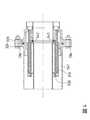
図3は、本発明によるプラグインカプリング300の例示的な実施形態を概略的に断面で示す。プラグインカプリング300は、連結プラグ301及び連結ソケット302を有し、これらは図3において、組み立てられる前の状態で、相互に小さい間隔をあけて示されている。 FIG. 3 schematically illustrates an exemplary embodiment of the plug-in
連結プラグ301は第一の極低温ライン303に接続され、連結ソケット302は第二の極低温ライン304に接続される。第一の極低温ライン303は、外管306及び内管307を有し、これらは中間空間308によって相互から分離され、中間間隔308内の断熱用真空によって相互に関して断熱される。極低温ライン303、304は、二重真空断熱極低温ラインである。 The connecting
連結プラグは第一の接続フランジ309を含み、これは円筒形取付け領域311へと移行する。取付け領域311は包囲する外側取付け部品312に接続され、その外周には極低温ライン303の外管306のための受容部313が形成される。外管306は取付け部品312に溶接される。さらに、取付け領域311は包囲する内側取付け部品314を有し、その内周に、極低温ライン303の内管307のための受容部316が形成される。内管307も同様に取付け部品314に溶接される。 The connecting plug includes a first connecting
外側管部品317及び内側管部品318は、取付け領域311に、極低温ライン303の反対側において溶接され、外側管部品317と内側管部品318とは半径方向に相互から離間され、それによって外側管部品317と内側管部品318との間に環状ギャップ319が形成される。取付け領域311から逸れた端において、外側管部品317と内側管部品とは接続リング321によって相互に真空密の状態で接続される。環状ギャップ319は少なくとも1つの流路322を介して第一の極低温ライン303の中間空間308に流れの点で接続され、それによって断熱用真空も環状ギャップ319の中に行き渡る。連結ソケット302に連結プラグ301を組み立てるために、固定ねじ(図示せず)のための貫通穴323が設けられる。 The
連結ソケット302は第二の連結フランジ324を有し、これは取付け領域326へと移行する。取付け領域326は包囲する外側取付け部品327に接続され、その外周に極低温ライン304の外管329のための受容部328が形成される。外管329は取付け部品327に溶接される。 The connecting
連結ソケット302の外側管部品330は、第二の接続フランジ324の中央開口331の中に溶接される。接続リング332によって、外側管部品330の、接続フランジ324から逸れた端は、連結ソケットの内側管部品333に真空密状態で接続される。内側管部品333のもう一方の端は、シールホルダ334の外周の受容部に溶接される。第二の極低温ライン304の内管336は、シールホルダ334の内周に溶接される。 The
第二の極低温ライン304の外管329及び内管336は中間空間337の境界を定め、その中に断熱用真空が行き渡る。連結ソケット302の内側管部品333と極低温ライン304の内管336との間に環状ギャップ338が形成され、これは中間空間337に流れの点で接続される。したがって、断熱用真空はまた、環状ギャップ338の中にも行き渡る。外側管部品331と内側管部品333との間に環状ギャップ339が形成され、これは接続リング332で閉じられ、反対側では第二の接続フランジ324の領域で開放し、それゆえ、連結プラグ301のための円形環状挿入穴を形成する。断熱用真空は、環状ギャップ339の周囲に延びる環状空間341の中にも同様に行き渡る。連結プラグに面する側の端において、シールホルダ334の上にシール342が配置され、これはプラグインカプリング300が組み立てられた状態で、連結プラグ301の台座343の上に乗り、それぞれ第一及び第二の極低温ライン303、304の内側媒質導管307、336を密閉する(図4)。 The
第二の接続フランジ324には、環状突出部344が形成され、これは連結プラグ301の第一の接続フランジ309の中の対応する凹部346に嵌る。接続リング321と第一の接続フランジ309との間の間隔は、連結プラグ301の長さL2に対応する。The second connecting
第二の接続フランジ324はさらに、環状溝347を有し、その中にシール348が受けられる。シール348は、シール342が内管307、336を完全に密閉していない場合に、蒸発した媒質がプラグインカプリング300から漏出するのを防止する。 The second connecting
図4は、組み立てられた状態のプラグインカプリング300を示し、接続フランジ309及び324が接続固定ねじ136によって相互に押し付けられている。環状突出部344は凹部346の中に受けられ、連結リング301を連結ソケット302上でセンタリングする。環状突出部344及び凹部346は相互に相補的なセンタリング手段を形成する。他の例示的な実施形態では、他のセンタリング手段を提供することも可能である。連結プラグ301は連結ソケット302の中に完全に差し込まれ、それによってシール342は連結プラグの台座343の上に乗り、内管306、336を密閉する。断熱用真空の3つの層がそれゆえ、プラグインカプリング300の領域の中で段々に積み重ねられる。これらは、半径方向に内側から外側に見て、連結ソケット302の環状ギャップ338、連結プラグ301の環状ギャップ319、及び連結ソケット302の環状空間341である。したがって、プラグインカプリング300の場合、外から入り込んだ熱が通らなければならない経路は連結プラグ301の長さL2のほぼ2倍である。プラグインカプリング300の長さが等しい場合、その断熱性は図2に示されるプラグインカプリング100より高い。FIG. 4 shows the plug-in
反対に、ある所定の断熱効果のために、プラグインカプリング300はプラグインカプリング100より短く設計されることになり、これはそれぞれ図1及び3に示される連結武具101及び301のそれぞれ異なる長さL1及びL2により説明され、L1はL2のほぼ1.3倍である。他の例示的な実施形態では、長さの割合も異なっていてよい。Conversely, for some given insulation effect, the plug-in
プラグインカプリング300の構造的長さがより短いことによって、その取扱いが容易になる。さらに、カプリンクグ300は省スペースで、シール342の領域におけるシーリングは、影響力の小さい角度公差によってより簡単になり、これは、連結プラグ301が連結ソケット302の中に正確に同心的に差し込まれないときの台座343の最適な位置からのずれが小さいからである。 The shorter structural length of the plug-in
100 プラグインカプリング
101 連結プラグ
102 連結ソケット
103 第一の極低温ライン
104 第二の極低温ライン
106 外管
107 内管
108 中間空間
109 第一の接続フランジ
111 外側管部品
112 内側管部品
113 遠位端
114 環状ギャップ
117 突出縁
118 シール
120 環状溝
121 シール
122 第二の接続フランジ
123 外側管部品
124 内側管部品
126 環状ギャップ
128 外管
129 内管
130 中間空間
131 接続リング
132 台座
300 プラグインカプリング
301 連結プラグ
302 連結ソケット
303 第一の極低温ライン
304 第二の極低温ライン
306 外管
307 内管
308 中間空間
309 第一の接続フランジ
311 取付け領域
312 外側取付け部品
313 受容部
314 内側取付け部品
316 受容部
317 外管
318 内管
319 環状ギャップ
321 接続リング
322 流路
323 貫通穴
324 第二の接続フランジ
326 取付け領域
327 外側取付け部品
328 受容部
329 外管
330 外管
331 中央開口
332 接続リング
333 内管
334 シールホルダ
336 内管
337 中間空間
338 環状ギャップ
339 開放環状ギャップ
340 挿入開口
341 環状空間
342 シール100 Plug-in
Claims (10)
Translated fromJapanese−前記連結プラグ(301)は、内側及び外側管部品(318、317)と、第一の接続フランジ(309)と、を有し、前記第一の極低温ライン(303)に接続され、
−前記連結ソケット(302)は、内側及び外側管部品(333、330)と、第二の接続フランジ(324)と、を有し、前記第二の極低温ライン(304)に接続され、
前記連結ソケット(302)の前記内側及び外側管部品(333、330)間に環状ギャップ(339)が形成され、これは前記第二の接続フランジ(324)の領域で開放し、その内周及びその外周の両方において断熱用真空(338、341)で取り囲まれることを特徴とするプラグインカプリング(300)。In the plug-in coupling for connecting the first double vacuum insulated cryogenic line (303) to the second double vacuum insulated cryogenic line (304), the plug-in coupling (300) is a connecting plug (301). ) And the connecting socket (302)
-The connecting plug (301) has inner and outer tube components (318, 317) and a first connecting flange (309) and is connected to the first cryogenic line (303).
-The connecting socket (302) has inner and outer tube components (333, 330) and a second connecting flange (324) and is connected to the second cryogenic line (304).
An annular gap (339) is formed between the inner and outer tube components (333, 330) of the connecting socket (302), which is opened in the region of the second connecting flange (324), the inner circumference thereof and the inner circumference thereof. A plug-in coupling (300) characterized in that both sides thereof are surrounded by adiabatic vacuum (338, 341).
Applications Claiming Priority (2)
| Application Number | Priority Date | Filing Date | Title |
|---|---|---|---|
| EP20305040.6AEP3851726B1 (en) | 2020-01-17 | 2020-01-17 | Johnston coupling with an additional vacuum cover |
| EP20305040.6 | 2020-01-17 |
Publications (1)
| Publication Number | Publication Date |
|---|---|
| JP2021113614Atrue JP2021113614A (en) | 2021-08-05 |
Family
ID=69423258
Family Applications (1)
| Application Number | Title | Priority Date | Filing Date |
|---|---|---|---|
| JP2021005380APendingJP2021113614A (en) | 2020-01-17 | 2021-01-15 | Johnston coupling with additional vacuum enclosure |
Country Status (3)
| Country | Link |
|---|---|
| US (1) | US11788666B2 (en) |
| EP (1) | EP3851726B1 (en) |
| JP (1) | JP2021113614A (en) |
Cited By (1)
| Publication number | Priority date | Publication date | Assignee | Title |
|---|---|---|---|---|
| JP2023136550A (en)* | 2022-03-17 | 2023-09-29 | 岩谷産業株式会社 | Connection joint structure |
Families Citing this family (9)
| Publication number | Priority date | Publication date | Assignee | Title |
|---|---|---|---|---|
| FR3119007B1 (en)* | 2021-01-19 | 2023-02-24 | Air Liquide | Emergency coupling and detachment device |
| KR20240028996A (en) | 2021-05-28 | 2024-03-05 | 엔지니어드 컨트롤스 인터내셔날, 엘엘씨 | Combination low-emission nozzles and receptacles for cryogenic fluids |
| US11913581B2 (en) | 2021-07-20 | 2024-02-27 | FirstElement Fuel, Inc. | Control conduit for LH2 offloading |
| FR3131949B1 (en)* | 2022-01-17 | 2023-12-08 | Air Liquide | Coupling device and its purging process |
| EP4239239A1 (en)* | 2022-01-19 | 2023-09-06 | Airbus Operations Limited | Coupling for insulated piping |
| CN117489971A (en)* | 2022-07-26 | 2024-02-02 | 南通中集能源装备有限公司 | Inlet and outlet structure and storage system |
| WO2024241280A1 (en)* | 2023-05-25 | 2024-11-28 | Fabrum Ip Holdings Limited | A hazardous fluid isolation system |
| FR3150562A1 (en)* | 2023-06-28 | 2025-01-03 | T.En Loading Systems | ROTATING CONNECTION DEVICE FOR CRYOGENIC FLUID PIPES |
| FR3150563A1 (en)* | 2023-06-28 | 2025-01-03 | T.En Loading Systems | ROTATING CONNECTION DEVICE FOR CRYOGENIC FLUID PIPES |
Citations (11)
| Publication number | Priority date | Publication date | Assignee | Title |
|---|---|---|---|---|
| US2980448A (en)* | 1958-03-24 | 1961-04-18 | Beech Aircraft Corp | Connector for joining pipelines having outer jacket insulation in continuously insulated relation |
| US3095220A (en)* | 1959-02-16 | 1963-06-25 | Herrick L Johnston Inc | Zero load pump flange connection |
| JPS5983891A (en)* | 1982-11-01 | 1984-05-15 | 株式会社日立製作所 | Cryogenic piping joint |
| JPS6091889U (en)* | 1983-11-30 | 1985-06-22 | 三菱重工業株式会社 | Cryogenic fluid double piping fitting |
| JPS60220297A (en)* | 1984-04-16 | 1985-11-02 | 東洋酸素株式会社 | Connecting section structure of cryogenic fluid transport pipe |
| JPH07208684A (en)* | 1994-01-28 | 1995-08-11 | Zojirushi Corp | Joint structure for vacuum double tube |
| US20020089177A1 (en)* | 1999-10-13 | 2002-07-11 | Bonn John W. | Controlled leak cryogenic bayonet pipe spool and system |
| US7052047B1 (en)* | 2002-03-21 | 2006-05-30 | Lockheed Martin Corporation | Detachable high-pressure flow path coupler |
| JP2009518591A (en)* | 2005-12-10 | 2009-05-07 | ネクサン | Plug-in fittings for cryogenic piping |
| CN105299352A (en)* | 2015-10-27 | 2016-02-03 | 天津彩意科技有限公司 | Novel pipe connection compression-resisting flange |
| CN211693828U (en)* | 2020-01-21 | 2020-10-16 | 辽阳正阳机械设备制造有限公司 | High-vacuum low-temperature liquid conveying pipeline special for coal mine |
Family Cites Families (4)
| Publication number | Priority date | Publication date | Assignee | Title |
|---|---|---|---|---|
| US3137143A (en)* | 1962-04-23 | 1964-06-16 | Robert B Jacobs | Condensing vacuum insulation |
| DE2164823A1 (en)* | 1971-12-27 | 1973-06-28 | Linde Ag | DEVICE FOR SUPPLYING AND EXHAUSTING A COLD GAS |
| CN102606821A (en)* | 2012-03-27 | 2012-07-25 | 航天晨光股份有限公司 | Flange joint of vacuum heat-insulation low-temperature pipeline |
| DE102015209124A1 (en)* | 2015-05-19 | 2016-11-24 | Linde Aktiengesellschaft | Coupling plug, coupling socket and coupling for cryogenic media |
- 2020
- 2020-01-17EPEP20305040.6Apatent/EP3851726B1/enactiveActive
- 2021
- 2021-01-14USUS17/149,341patent/US11788666B2/enactiveActive
- 2021-01-15JPJP2021005380Apatent/JP2021113614A/enactivePending
Patent Citations (11)
| Publication number | Priority date | Publication date | Assignee | Title |
|---|---|---|---|---|
| US2980448A (en)* | 1958-03-24 | 1961-04-18 | Beech Aircraft Corp | Connector for joining pipelines having outer jacket insulation in continuously insulated relation |
| US3095220A (en)* | 1959-02-16 | 1963-06-25 | Herrick L Johnston Inc | Zero load pump flange connection |
| JPS5983891A (en)* | 1982-11-01 | 1984-05-15 | 株式会社日立製作所 | Cryogenic piping joint |
| JPS6091889U (en)* | 1983-11-30 | 1985-06-22 | 三菱重工業株式会社 | Cryogenic fluid double piping fitting |
| JPS60220297A (en)* | 1984-04-16 | 1985-11-02 | 東洋酸素株式会社 | Connecting section structure of cryogenic fluid transport pipe |
| JPH07208684A (en)* | 1994-01-28 | 1995-08-11 | Zojirushi Corp | Joint structure for vacuum double tube |
| US20020089177A1 (en)* | 1999-10-13 | 2002-07-11 | Bonn John W. | Controlled leak cryogenic bayonet pipe spool and system |
| US7052047B1 (en)* | 2002-03-21 | 2006-05-30 | Lockheed Martin Corporation | Detachable high-pressure flow path coupler |
| JP2009518591A (en)* | 2005-12-10 | 2009-05-07 | ネクサン | Plug-in fittings for cryogenic piping |
| CN105299352A (en)* | 2015-10-27 | 2016-02-03 | 天津彩意科技有限公司 | Novel pipe connection compression-resisting flange |
| CN211693828U (en)* | 2020-01-21 | 2020-10-16 | 辽阳正阳机械设备制造有限公司 | High-vacuum low-temperature liquid conveying pipeline special for coal mine |
Cited By (2)
| Publication number | Priority date | Publication date | Assignee | Title |
|---|---|---|---|---|
| JP2023136550A (en)* | 2022-03-17 | 2023-09-29 | 岩谷産業株式会社 | Connection joint structure |
| JP7553033B2 (en) | 2022-03-17 | 2024-09-18 | 岩谷産業株式会社 | Connection joint structure |
Also Published As
| Publication number | Publication date |
|---|---|
| US11788666B2 (en) | 2023-10-17 |
| EP3851726B1 (en) | 2024-12-18 |
| EP3851726C0 (en) | 2024-12-18 |
| EP3851726A1 (en) | 2021-07-21 |
| US20210278028A1 (en) | 2021-09-09 |
Similar Documents
| Publication | Publication Date | Title |
|---|---|---|
| JP2021113614A (en) | Johnston coupling with additional vacuum enclosure | |
| CN111512081B (en) | Fluid Handling Fittings and Fluid Handling Units | |
| US20080169037A1 (en) | Cryogenic bayonet connection | |
| US8267433B2 (en) | Plug-in coupling for cryogenic lines | |
| WO2019131784A1 (en) | Loading arm connector | |
| US3371946A (en) | Cryogenic coupling | |
| JP2006038223A (en) | Seal for pipe device | |
| JP2021113615A (en) | Johnston coupling with galvanic insulation | |
| JP2016070374A (en) | High heat-insulation joint structure of vacuum heat-insulating double pipe for low-temperature fluid | |
| US3945215A (en) | Low-loss, fluid helium transfer line suitable for extended lengths | |
| CN114017507A (en) | Vacuum low-temperature valve for liquid helium and liquid hydrogen | |
| US4106796A (en) | Connector for duct systems for low temperature fluids | |
| JP2016070375A (en) | Joint structure of vacuum heat-insulating double pipe for low-temperature fluid | |
| KR101639189B1 (en) | Joint structure of vacuum insulate pipe | |
| CN107806537A (en) | cryogenic transfer line | |
| CN107725972A (en) | A kind of vacuum interlayer cryogenic fluid transfer pipeline | |
| CN207471021U (en) | A kind of vacuum interlayer cryogenic fluid transfer pipeline | |
| CN115388250B (en) | A low temperature joint | |
| CN114076257A (en) | Low temperature container and pipeline thereof | |
| KR101294138B1 (en) | Valve for use in extremely low temperature | |
| CN106641548A (en) | Low-temperature connector | |
| KR102443559B1 (en) | Expanding joint of liquid hydrogen transfer vacuum insulated pipe | |
| CN218954364U (en) | Pipeline vacuum insulation protection device | |
| CN219692492U (en) | Supporting structure of vacuum heat insulation double-wall pipe and double-wall pipe for LNG fuel tank | |
| US12098794B2 (en) | Cryogenic rotating seal |
Legal Events
| Date | Code | Title | Description |
|---|---|---|---|
| A621 | Written request for application examination | Free format text:JAPANESE INTERMEDIATE CODE: A621 Effective date:20240109 | |
| A977 | Report on retrieval | Free format text:JAPANESE INTERMEDIATE CODE: A971007 Effective date:20241218 | |
| A131 | Notification of reasons for refusal | Free format text:JAPANESE INTERMEDIATE CODE: A131 Effective date:20241224 | |
| A601 | Written request for extension of time | Free format text:JAPANESE INTERMEDIATE CODE: A601 Effective date:20250324 | |
| A521 | Request for written amendment filed | Free format text:JAPANESE INTERMEDIATE CODE: A523 Effective date:20250624 | |
| A02 | Decision of refusal | Free format text:JAPANESE INTERMEDIATE CODE: A02 Effective date:20250902 |