JP2021111233A - Work shift generator, work shift generation method, and program - Google Patents
Work shift generator, work shift generation method, and programDownload PDFInfo
- Publication number
- JP2021111233A JP2021111233AJP2020003965AJP2020003965AJP2021111233AJP 2021111233 AJP2021111233 AJP 2021111233AJP 2020003965 AJP2020003965 AJP 2020003965AJP 2020003965 AJP2020003965 AJP 2020003965AJP 2021111233 AJP2021111233 AJP 2021111233A
- Authority
- JP
- Japan
- Prior art keywords
- shift
- work
- work shift
- period
- generation
- Prior art date
- Legal status (The legal status is an assumption and is not a legal conclusion. Google has not performed a legal analysis and makes no representation as to the accuracy of the status listed.)
- Granted
Links
- 238000000034methodMethods0.000titleclaimsabstractdescription43
- 238000011156evaluationMethods0.000claimsdescription18
- 238000004891communicationMethods0.000description31
- 238000012937correctionMethods0.000description11
- 238000012545processingMethods0.000description9
- 238000010586diagramMethods0.000description8
- 230000006870functionEffects0.000description6
- 238000004364calculation methodMethods0.000description4
- 230000005540biological transmissionEffects0.000description2
- 230000000694effectsEffects0.000description2
- 239000000284extractSubstances0.000description2
- 230000002068genetic effectEffects0.000description2
- 238000012797qualificationMethods0.000description2
- 230000002040relaxant effectEffects0.000description2
- 239000004065semiconductorSubstances0.000description2
- 230000003442weekly effectEffects0.000description2
- 239000008186active pharmaceutical agentSubstances0.000description1
- 238000007796conventional methodMethods0.000description1
- 238000012986modificationMethods0.000description1
- 230000004048modificationEffects0.000description1
- 238000004904shorteningMethods0.000description1
- 239000007787solidSubstances0.000description1
- 230000007306turnoverEffects0.000description1
Images


Landscapes
- Management, Administration, Business Operations System, And Electronic Commerce (AREA)
Abstract
Translated fromJapaneseDescription
Translated fromJapanese本発明は、勤務シフトを生成する技術に関する。 The present invention relates to a technique for generating work shifts.
勤務シフトの作成を支援する技術が知られている。特許文献1には、勤労者からみて納得性の高い勤務シフトを作成することを意図した勤務シフト作成支援装置が記載されている。 Techniques are known to assist in the creation of work shifts.
しかしながら、上述のような従来技術を用いて勤務シフトを生成する場合、以下の課題がある。 However, when the work shift is generated by using the conventional technique as described above, there are the following problems.
既知のアルゴリズムを用いて勤務シフトを生成する場合、通常の慣習に沿わない勤務シフトが生成される場合がある。また、勤務シフトを生成するための計算量が増大する傾向がある。 When generating work shifts using known algorithms, work shifts that do not follow normal conventions may be generated. Also, the amount of calculation for generating work shifts tends to increase.
本発明の一態様は、上述した課題を解決するためになされたものであり、通常の慣習に沿わない勤務シフトが生成されることを防ぐと共に、勤務シフトの生成に要する時間を短縮する技術を実現することを目的とする。 One aspect of the present invention has been made to solve the above-mentioned problems, and is a technique for preventing the generation of work shifts that do not conform to the usual customs and shortening the time required for the generation of work shifts. The purpose is to realize it.
上記の課題を解決するために、本発明の一態様に係る勤務シフト生成装置は、制約条件を示す制約条件情報を取得する取得部と、前記制約条件情報が示す制約条件を満たす勤務シフトを、予め用意されている複数のシフトパターンを組み合わせることによって生成する生成部とを備える。 In order to solve the above problems, the work shift generator according to one aspect of the present invention has an acquisition unit that acquires constraint condition information indicating a constraint condition, and a work shift that satisfies the constraint condition information indicated by the constraint condition information. It includes a generation unit that is generated by combining a plurality of shift patterns prepared in advance.
本発明の各態様に係る勤務シフト生成装置は、コンピュータによって実現してもよく、この場合には、コンピュータを前記勤務シフト生成装置が備える各部(ソフトウェア要素)として動作させることにより前記勤務シフト生成装置をコンピュータにて実現させる勤務シフト生成装置の制御プログラム、およびそれを記録したコンピュータ読み取り可能な記録媒体も、本発明の範疇に入る。 The work shift generator according to each aspect of the present invention may be realized by a computer. In this case, the work shift generator is operated by operating the computer as each part (software element) included in the work shift generator. The control program of the work shift generator and the computer-readable recording medium on which the control program is recorded are also included in the scope of the present invention.
本発明の一態様によれば、通常の慣習に沿わない勤務シフトが生成されることを防ぐと共に、勤務シフトの生成に要する時間を短縮することができる。 According to one aspect of the present invention, it is possible to prevent the generation of work shifts that do not conform to the usual customs and to shorten the time required to generate the work shifts.
以下、本発明の一実施形態に係る勤務シフト生成システム1について説明する。 Hereinafter, the work
<勤務シフト生成システム1の概要>
図1は、本発明の一実施形態に係る勤務シフト生成システム1の機能的な構成を示すブロック図である。図1に示すように、勤務シフト生成システム1は、勤務シフト生成装置10、ユーザが操作するユーザ端末20、及び従業者が操作する従業者端末30を含んでいる。ここで、図1に示す例では、勤務シフト生成システム1が、ユーザ端末20、及び従業者端末30をそれぞれ1つ含んでいるが、これは本実施形態を限定するものでははい。勤務シフト生成システム1は、ユーザ端末20及び従業者端末30をそれぞれ複数含む構成としてもよい。<Overview of work
FIG. 1 is a block diagram showing a functional configuration of the work
勤務シフト生成装置10と、ユーザ端末20と、従業者端末30とは、ネットワークN1を介して通信可能に接続される。勤務シフト生成装置10と、ユーザ端末20と、従業者端末30を接続するネットワークN1は、有線LAN(Local Area Network)、無線LAN、インターネット、公衆回線網、モバイルデータ通信網、またはこれらの組み合わせである。 The
勤務シフト生成システム1は、一例として、複数の従業者を雇用している店舗の管理者により使用されることを想定している。ここで、店舗の管理者は、勤務シフトを作成したり管理したりする者であり、本実施形態における「ユーザ」の一例である。 The work
また、本実施形態において、「従業者」とは、勤務シフト生成システム1が生成した勤務シフトに従って勤務する者のことであり、会社の社員、派遣社員、アルバイトおよびパートタイマーなどが含まれる。 Further, in the present embodiment, the “employee” is a person who works according to the work shift generated by the work
勤務シフト生成装置10は、制約条件を示す制約条件情報を取得し、制約条件情報が示す制約条件を満たす勤務シフトを、予め用意されている複数のシフトパターンを組み合わせることによって生成する。 The work
ここで、制約条件とは、生成される勤務シフトが満たすべき条件の一例である。本実施形態における制約条件には、日次シフト条件、期間シフト条件、店舗シフト条件、及び法令シフト条件という4つ側面が含まれる。制約条件の詳細については後述する。 Here, the constraint condition is an example of the condition that the generated work shift should satisfy. The constraint conditions in the present embodiment include four aspects: a daily shift condition, a period shift condition, a store shift condition, and a legal shift condition. The details of the constraints will be described later.
また、シフトパターンとは、一例として、予め複数設定された「勤務時間および休憩時間の組」のことである。シフトパターンの詳細については、後述する。 Further, the shift pattern is, for example, a plurality of preset "sets of working hours and break times". The details of the shift pattern will be described later.
また、本実施形態における「勤務シフト」との文言には、後述する日次勤務シフト、及び期間勤務シフトの双方が含まれる。 In addition, the wording "work shift" in the present embodiment includes both daily work shift and fixed-term work shift, which will be described later.
勤務シフト生成システム1によれば、通常の慣習に沿わない勤務シフトが生成されることを防ぐと共に、勤務シフトの生成に要する時間を短縮することが可能になる。ここで、通常の慣習に沿わない勤務シフトとは、「勤務と休憩を高頻度に繰り返す」、「勤務時間の開始を休憩から始める」、「勤務開始と退勤を1回のシフトの中で繰り返す」などの勤務シフトである。例えば、「5分間勤務し、退勤し、1時間後に、5分間勤務し、退勤する」というような勤務シフトである。 According to the work
また、勤務シフトの生成に要する時間を短縮することを可能にするとは、既知のアルゴリズムを使用して勤務シフトを生成する場合よりも、必要な計算量が少なくて済む、ということである。整数計画法などの既知のアルゴリズムを使用して勤務シフトを生成する場合、勤務シフトの単位時間が短くなるにつれ、計算量が増大する傾向にある。勤務シフトの生成に必要な計算量が増大するにつれ、勤務シフトの生成に要する時間は長くなる傾向がある。 Also, making it possible to reduce the time required to generate work shifts means that less calculation is required than when generating work shifts using a known algorithm. When generating work shifts using a known algorithm such as integer programming, the amount of calculation tends to increase as the unit time of work shifts becomes shorter. As the amount of calculation required to generate work shifts increases, the time required to generate work shifts tends to increase.
勤務シフト生成システム1によれば、予め用意されているシフトパターンを組み合わせることにより勤務シフトを生成するので、既知のアルゴリズムのみを用いて勤務シフトを生成するよりも、勤務シフトの生成に要する時間を短縮することが可能となる。 According to the work
(勤務シフト生成装置10の構成)
続いて、図1を参照して勤務シフト生成装置10の構成について説明する。図1に示すように、勤務シフト生成装置10は、通信部11と、制御部13と、記憶部15とを含む。制御部13は、取得部130と、生成部131と、更新部133と、評価部135とを含む。(Configuration of work shift generator 10)
Subsequently, the configuration of the work
記憶部15は、シフトパターンを記憶する。また、記憶部15には、制約条件、及び、後述する生成処理によって生成部131が生成した勤務シフトが更に格納される。 The
通信部11は、ネットワークN1を介してユーザ端末20および従業者端末30と通信を行う。 The
取得部130は、記憶部15又は通信部11から、制約条件を示す制約条件情報および対象期間における対象店舗の従業者の希望シフトを取得する。 The
生成部131は、取得部130が取得した制約条件情報が示す制約条件を満たす勤務シフトを、予め用意されている複数のシフトパターンを組み合わせることによって生成する。生成部131による勤務シフトの具体的な生成処理については後述する。 The
更新部133は、複数のシフトパターンに含まれる少なくとも何れかのシフトパターンを更新する。一例として、更新部133は、ユーザ端末20から取得した修正指示に基づき、複数のシフトパターンに含まれる少なくとも何れかのシフトパターンを修正する。 The
更新部133がシフトパターンを更新することによって、生成部131は、より好適なシフトパターンを用いて勤務シフトを生成することができる。 By updating the shift pattern by the
上記のようにシフトパターンを更新することによって、より好適なシフトパターンを用いて勤務シフトを生成することができる。 By updating the shift pattern as described above, work shifts can be generated using a more suitable shift pattern.
また、更新部133は、生成部131が生成した勤務シフトを、ユーザ端末20又は従業者端末30から取得した修正指示に基づき修正する構成としてもよい。 Further, the
評価部135は、勤務シフト生成装置10を利用する複数のユーザのそれぞれに対する評価を示す評価情報を生成する。生成した評価情報は、記憶部15に記憶される。ここで、評価部135は、例えば、以下のような場合に、ユーザに対して高い評価を行う。
・当該ユーザの店舗では他の店舗に比べて退職率が低い
・当該ユーザの店舗での平均勤続年数が他の店舗に比べて長い
・当該ユーザへの従業者からの信頼度が他の店舗に比べて高い
・当該ユーザの店舗での従業者満足度が他の店舗に比べて高い
・当該ユーザの店舗での欠員が他の店舗の比べて少ない、等。The
・ The turnover rate of the user's store is lower than that of other stores. ・ The average length of service at the user's store is longer than that of other stores. ・ The reliability of the user from employees is higher than that of other stores. Compared to other stores ・ Employee satisfaction at the user's store is higher than other stores ・ Vacancy at the user's store is smaller than at other stores, etc.
評価部135による評価は、後述するようにシフトパターンの設定処理において参照される。 The evaluation by the
(ユーザ端末20の構成)
続いて、図1を参照してユーザ端末20の構成について説明する。図1に示すように、ユーザ端末20は、通信部21と、制御部23と、入力部25と、表示部27とを含む。ユーザ端末20は、PC、タブレット端末、及びスマートフォン等として実現できるが、これらの具体的態様は本実施形態を限定するものではない。(Configuration of user terminal 20)
Subsequently, the configuration of the
通信部21は、ネットワークN1を介して勤務シフト生成装置10および従業者端末30と通信を行う。制御部23は、ユーザ端末20の各部を制御する。入力部25はユーザからの入力を受け付け、受け付けた入力を示す入力情報を制御部23に供給する。表示部27は、制御部23による制御に従って画像を表示する。 The
一例として、入力部25は、ユーザから、制約条件、及び希望シフトに関する入力を受け付ける。そして、制御部23は、当該入力が示す制約条件及び希望シフトを、通信部21を介して勤務シフト生成装置10に対して送信する。 As an example, the
また、入力部25は、シフトパターンの修正及び勤務シフトの修正に関する入力を受け付け、制御部23は、当該入力が示す修正指示を勤務シフト生成装置10に対して送信する。 Further, the
また、一例として、通信部21は勤務シフト生成装置10から勤務シフトを受信し、制御部23は、受信した勤務シフトを表示部27に表示させる。表示部27は、従業者端末30から受信した従業者のメッセージを表示する構成としてもよい。表示部27による具体的な表示例については後述する。 Further, as an example, the
(従業者端末30の構成)
続いて、図1を参照して従業者端末30の構成について説明する。図1に示すように、従業者端末30は、通信部31と、制御部33と、入力部35と、表示部37とを含む。従業者端末30は、PC、タブレット端末、及びスマートフォン等として実現できるが、これらの具体的態様は本実施形態を限定するものではない。(Configuration of employee terminal 30)
Subsequently, the configuration of the
通信部31は、ネットワークN1を介して勤務シフト生成装置10およびユーザ端末20と通信を行う。制御部33は、従業者端末30の各部を制御する。入力部35は従業者からの入力を受け付け、受け付けた入力を示す入力情報を制御部33に供給する。表示部37は、制御部33による制御に従って画像を表示する。 The
一例として、入力部35は、従業者から、希望シフトに関する入力を受け付ける。そして、制御部33は、当該入力が示す希望シフトを、通信部21を介して勤務シフト生成装置10、又は、ユーザ端末20に対して送信する。 As an example, the
また、入力部35は、勤務シフトの修正に関する入力を受け付け、制御部33は、当該入力が示す修正指示をユーザ端末20に対して送信する。 Further, the
また、一例として、通信部31は勤務シフト生成装置10から勤務シフトを受信し、制御部33は、受信した勤務シフトを表示部37に表示させる。表示部37は、ユーザ端末30から受信したユーザのメッセージを表示する構成としてもよい。表示部37による具体的な表示例については後述する。 Further, as an example, the
<勤務シフト生成システム1の勤務シフト生成処理>
以下では、本発明の一実施形態に係る勤務シフト生成システム1の勤務シフト生成処理について詳細に説明する。<Work shift generation process of work
Hereinafter, the work shift generation process of the work
図2は、本発明の一実施形態に係る勤務シフト生成装置10が実行する勤務シフト生成処理の流れを示すフローチャートである。 FIG. 2 is a flowchart showing a flow of work shift generation processing executed by the work
(ステップS101)
ステップS101において、勤務シフト生成装置10の取得部130は、対象期間における対象店舗の従業者の希望シフトを、通信部11を介して取得する。(Step S101)
In step S101, the
ここで、対象期間とは、勤務シフトの生成対象となる任意の期間である。対象期間の例としては、「翌週」、「翌2週間」、「翌月」などが挙げられるが、これらの例は本実施形態を限定するものではない。 Here, the target period is an arbitrary period for which work shifts are generated. Examples of the target period include “next week”, “next two weeks”, “next month”, and the like, but these examples do not limit the present embodiment.
また、対象店舗とは、勤務シフトの生成対象である店舗のことである。勤務シフト生成装置10は、店舗IDを用いることによって、複数の店舗を互いに識別することができる。店舗IDとは、勤務シフト生成装置10が店舗同士を識別するための識別番号である。 The target store is a store for which work shifts are generated. The work
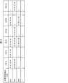
また、希望シフトとは、対象期間に含まれる日毎及び従業者毎の勤務希望時間帯を示す情報である。図3は、本実施形態に係る希望シフトの例であって、対象期間が1月1日〜1月31日の1ヶ月間である希望シフトの例である。図3に示すように、希望シフトには、対象期間に含まれる日毎及び従業者毎の勤務希望時間帯が含まれている。図3に例示した希望シフトは、1月1日に、従業者識別番号(EID)がE001の従業者が9:00〜18:00の勤務を希望しており、E002の従業者が18:00〜22:00の勤務を希望しており、E003の従業者は勤務を希望していないことを示している。 The desired shift is information indicating the desired working hours for each day and each employee included in the target period. FIG. 3 is an example of a desired shift according to the present embodiment, and is an example of a desired shift in which the target period is one month from January 1st to January 31st. As shown in FIG. 3, the desired shift includes the desired working hours for each day and each employee included in the target period. In the desired shift illustrated in FIG. 3, on January 1, an employee with an employee identification number (EID) of E001 wants to work from 9:00 to 18:00, and an employee with E002 wants to work at 18: They want to work from 00 to 22:00, indicating that E003 employees do not want to work.
なお、本ステップにおける希望シフトの取得方法として以下の例が挙げられる。 The following example can be given as a method of acquiring the desired shift in this step.
(1)従業者が従業者端末30に入力した希望シフトを、従業者端末30が勤務シフト生成装置10に送信し、取得部130が取得する。 (1) The
(2)従業者が従業者端末30に入力した希望シフトを、従業者端末30からユーザ端末20に送信する。そして、当該希望シフトをユーザ端末20が勤務シフト生成装置10に送信し、取得部130が取得する。 (2) The desired shift input by the employee to the
(3)従業者からユーザ端末20のユーザに対して、口頭、電話、書面、チャット、メールなどにより伝達し、伝達された内容が反映された希望シフトをユーザがユーザ端末20に入力する。そして、ユーザ端末20が当該希望シフトを勤務シフト生成装置10に送信し、取得部130が取得する。 (3) The employee transmits to the user of the
(ステップS102)
続いて、ステップS102において、取得部130は、制約条件を取得する。取得部130が取得する制約条件は、ユーザがユーザ端末20において設定し、通信部11を介して取得されるものであってもよいし、予め記憶部15に記憶されたものであってもよい。(Step S102)
Subsequently, in step S102, the
図4は、本実施形態に係る制約条件の例である。上述したように、本実施形態に係る制約条件は、日次シフト条件、期間シフト条件、店舗シフト条件、及び法令シフト条件という4つの側面が含まれる。 FIG. 4 is an example of the constraint conditions according to the present embodiment. As described above, the constraint conditions according to the present embodiment include four aspects: daily shift condition, period shift condition, store shift condition, and legal shift condition.
ここで、日次シフト条件とは、日次でシフトが満たすべき条件のことである。期間シフト条件とは、週次、月次などの所定期間でシフトが満たすべき条件のことである。店舗シフト条件とは、シフトが満たすべき店舗固有の条件のことである。法令シフト条件とは、法令により定められたシフトの条件のことである。 Here, the daily shift condition is a condition that the shift must satisfy on a daily basis. The period shift condition is a condition that the shift must satisfy in a predetermined period such as weekly or monthly. The store shift condition is a store-specific condition that the shift must meet. The decree shift condition is the shift condition stipulated by the decree.
図4に示すように、店舗シフト条件には、日次シフト条件として、
・日次の時間帯毎の職務毎の必要人数、能力、及び資格
を示す情報が含まれており、期間シフト条件として、
・各従業者の週次の希望勤務日数
・各従業者の月次の希望勤務日数
が含まれている。As shown in FIG. 4, the store shift condition includes the daily shift condition.
・ Information showing the required number of people, abilities, and qualifications for each job for each daily time zone is included, and as a period shift condition,
・ Weekly desired working days for each employee ・ Monthly desired working days for each employee are included.
また、法令シフト条件には、日次シフト条件として、
・各従業者の日次の勤務時間の制限
・日次の勤務時間に対する休憩時間の制限
・資格者の設置義務
を示す情報が含まれており、期間シフト条件として、
・各従業者の月次の勤務日数の制限
・各従業者の連続勤務日数の制限
・前日勤務から翌日勤務までの間隔の制限
を示す情報が含まれている。In addition, the decree shift conditions include daily shift conditions.
・ Daily working hours restrictions for each employee ・ Break time restrictions for daily working hours ・ Information indicating the obligation to set up qualified personnel is included, and as a period shift condition,
-Contains information that indicates the limit on the number of monthly working days for each employee, the limit on the number of consecutive working days for each employee, and the limit on the interval from the previous day's work to the next day's work.
(ステップS103)
続いて、ステップS103において、生成部131は、対象期間において、勤務シフトを生成する対象日を選択する。(Step S103)
Subsequently, in step S103, the
(ステップS104)
続いて、ステップS104において、生成部131は、記憶部15に記憶されているシフトパターンを組み合わせることによって、対象日における日次シフト条件及び希望シフトを満たす日次勤務シフトを複数生成する。(Step S104)
Subsequently, in step S104, the
図5は、本実施形態に係るシフトパターンの例である。図5に示すように各シフトパターンには、当該シフトパターンの識別番号(sp1、sp2、・・・)と、勤務を示す時間帯と休憩を示す時間帯とが互いに関連付けられて含まれている。 FIG. 5 is an example of a shift pattern according to the present embodiment. As shown in FIG. 5, each shift pattern includes an identification number (sp1, sp2, ...) Of the shift pattern, and a time zone indicating work and a time zone indicating a break are associated with each other. ..
例えば、図5に示すシフトパターンsp1は、9:00〜13:00の勤務時間と、13:00〜14:00の休憩時間と、14:00〜18:00の勤務時間とを含んでいる。 For example, the shift pattern sp1 shown in FIG. 5 includes working hours from 9:00 to 13:00, break times from 13:00 to 14:00, and working hours from 14:00 to 18:00. ..
なお、一例として、記憶部15には、100〜200種類程度のシフトパターンが記憶されている構成とすることができるが、これは本実施形態を限定するものではない。また、シフトパターンが示す勤務時間と休憩時間の単位時間は、一例として15分とすることができるが、これも本実施形態を限定するものではなく、例えば、時間単位を10分としてもよいし、5分としてもよいし、30分等としてもよい。 As an example, the
また、本ステップにおいて参照するシフトパターンを予めどのように設定しておくのかについては、後述する。 As for the one setting the shift pattern to be referred to in the present step in advance what will be described later.
本ステップでは、生成部131は、一例として、対象日の日次勤務シフトを探索する整数計画問題を立式し、整数計画法のソルバーにより解を探索する。生成部131は、対象日の勤務シフトが、日次シフト条件を満たすように、かつ、解の探索に使用するシフトパターンが当該対象日における希望シフトを満たすように解を探索する。その際、目的関数は任意に設定することができるが、一例として、勤務者数が最小になるように目的関数を設定しておくことができる。 In this step, as an example, the
図6は、本ステップにおいて生成部131が生成した日次勤務シフトの例(日次勤務シフト1、2)を示す図である。図6に示すように、日次勤務シフト1、2は共に、各従業員の希望シフトを満たしている。 FIG. 6 is a diagram showing an example of daily work shifts (daily work shifts 1 and 2) generated by the
なお、本ステップにおいて生成部131が解の探索に用いるアルゴリズムは整数計画法に限定されるものではなく、例えば、遺伝的アルゴリズムやバックトラッキング法などでもよい。 The algorithm used by the
(ステップS105)
ステップS105において、生成部131は、対象日の日時勤務シフト生成の終了条件が満たされているか否かを判断する。終了条件が満たされる場合(ステップS105のYES)は、ステップS106へと進み、終了条件が満たされない場合(ステップS105のNO)は、ステップS104へと戻り、更なる日次勤務シフトの生成を行う。(Step S105)
In step S105, the
ここで、終了条件とは、例えば、
・ステップS104における探索時間が所定の時間(例えば10分)以上となった
・ステップS104において生成された日次勤務シフトの数が所定の数(例えば10個)以上となった
等が挙げられる。Here, the end condition is, for example,
-The search time in step S104 is a predetermined time (for example, 10 minutes) or more.-The number of daily work shifts generated in step S104 is a predetermined number (for example, 10 minutes) or more.
(ステップS106)
続いて、ステップS106において、生成部131は、対象期間に含まれる全ての日の勤務シフトを生成したか否かを判断する。対象期間に含まれる全ての日の勤務シフトを生成した場合(ステップS106のYES)、ステップS107へと進み、対象期間に含まれる少なくとも一部の日の勤務シフトを生成していない場合(ステップS106のNO)、ステップS103へと戻る。(Step S106)
Subsequently, in step S106, the
例えば、対象期間において、勤務シフトを生成していない日がある場合、生成部131は、勤務シフトを生成していない日を新たな対象日として選択し、ステップS103へと戻る。 For example, if there is a day in which the work shift is not generated in the target period, the
(ステップS107)
ステップS107において、生成部131は、ステップS104において生成した日次勤務シフトを組み合わせることにより、対象期間の全日に関する日次勤務シフトを含む対象期間勤務シフトを生成する。(Step S107)
In step S107, the
一例として、生成部131は、対象期間の勤務シフトを探索する整数計画問題を立式し、整数計画法のソルバーにより解を探索する。ここで、生成部131は、対象期間の勤務シフトが、期間シフト条件を満たすように解を探索する。その際、目的関数は任意に設定することができるが、一例として、勤務者数が最小になるように目的関数を設定しておくことができる。 As an example, the
図7は、本ステップにおいて生成部131が生成した対象期間勤務シフトの例である。図7に示すように、生成部131は、ステップS104において日毎に複数生成した日次勤務リストから、日毎に1つの日次勤務リストを選択することによって、対象期間勤務シフトを生成する。 FIG. 7 is an example of the target period work shift generated by the
図7に示す例では、1月1日の日次勤務シフト1〜4のうち、日次勤務シフト4を選択し、1月2日の日次勤務シフト1〜4のうち、日次勤務シフト1を選択し、のように処理を続け、1月31の日次勤務シフト1〜4のうち、日次勤務シフト4を選択することによって対象期間勤務シフトが生成されている。 In the example shown in FIG. 7, the daily work shift 4 is selected from the daily work shifts 1 to 4 on January 1, and the daily work shift 4 is selected from the daily work shifts 1 to 4 on January 2. The target period work shift is generated by selecting 1 and continuing the process as in, and selecting the daily work shift 4 from the daily work shifts 1 to 4 of January 31.
なお、本ステップにおいて生成部131が解の探索に用いるアルゴリズムは整数計画法に限定されるものではなく、例えば、遺伝的アルゴリズム、やバックトラッキング法などでもよい。 The algorithm used by the
(ステップS108)
ステップS108において、勤務シフト生成装置10の通信部11は、ステップS107において生成部131が生成した対象期間勤務シフトをユーザ端末20へと送信する。そして、ユーザ端末20の表示部27は、勤務シフト生成装置10から送信され通信部21により取得された対象期間勤務シフトを表示する。なお、生成した対象期間の勤務シフトは、ユーザ端末20および従業者端末30の双方に送信される構成としてもよい。また、生成した対象期間の勤務シフトの表示の仕方は本実施形態を限定するものではないが、例えば、表形式やグラフ形式等が挙げられる。(Step S108)
In step S108, the
以上のように、生成部131は、制約条件を満たす勤務シフトを、予め用意されている複数のシフトパターンを組み合わせることによって生成するので、既知のアルゴリズムのみを用いて勤務シフトを生成するよりも、勤務シフトの生成に要する時間を短縮することができる。 As described above, since the
また、ステップS103〜ステップS107に示したように、生成部131は、第1の期間に複数含まれる第2の期間毎に勤務シフトを生成し、生成した第2の期間毎の勤務シフトを参照して、第1の期間における勤務シフトを生成する。 Further, as shown in steps S103 to S107, the
より具体的には、生成部131は、第1の期間に複数含まれる第2の期間毎に勤務シフトを複数生成し、生成した複数の勤務シフトから、第2の期間毎に1つの勤務シフトを選択することによって、第1の期間における勤務シフトを生成する。 More specifically, the
ここで、第1の期間は、上述した「対象期間」であり、第2の期間は、一例として上述した「対象日」である。 Here, the first period is the above-mentioned "target period", and the second period is the above-mentioned "target date" as an example.
生成部131は、上記のように、勤務シフトを階層的に生成するので、効率的に勤務シフトを生成することができる。 As described above, the
なお、第1の期間(対象期間)及び第2の期間は上述した例に限定されるものではなく、
・第1の期間:1年、第2の期間:1ヶ月
・第1の期間:1年、第2の期間:1週間
のように設定してもよい。The first period (target period) and the second period are not limited to the above-mentioned examples.
-First period: 1 year, second period: 1 month-First period: 1 year, 2nd period: 1 week.
また、上記の例では、第1の期間、及び第2の期間という2階層での勤務シフト生成処理について説明したが、これも本実施形態を限定するものではない。 Further, in the above example, the work shift generation process in two layers of the first period and the second period has been described, but this also does not limit the present embodiment.
例えば、生成部131は、第3の期間での勤務シフトを生成し、当該第3の期間での勤務シフトを参照して第2の期間での勤務シフトを生成し、当該第2の期間での勤務シフトを参照して第1の期間での勤務シフトを生成する構成としてもよい。ここで、第3の期間は第2の期間に複数含まれる期間である。一例として、第1の期間として1年、第2の期間として1ヶ月、第3の期間として1日又は1週間という期間が挙げられる。 For example, the
<ステップS104にて参照するシフトパターンの設定方法>
以下ではシフトパターンの設定方法について説明する。ステップS104において生成部131が参照するシフトパターンは、例えば以下のように設定されている。<Method of setting the shift pattern referred to in step S104>
The method of setting the shift pattern will be described below. The shift pattern referred to by the
(設定例1)
勤務シフト生成装置10に予めデフォルトとしてシフトパターンが記憶されている。(Setting example 1)
The shift pattern is stored in advance in the
(設定例2)
ユーザ端末20を介してシフトパターンをユーザが設定する。例えば、ユーザ端末20の表示部27が、シフトパターンの候補を一覧表示し、ユーザが当該一覧の候補から、所望のシフトパターンを選択する。選択されたシフトパターンは、ユーザ端末20が勤務シフト生成装置10に送信し、勤務シフト生成装置10の取得部130が記憶部15に格納する。(Setting example 2)
The user sets the shift pattern via the
(設定例3)
生成部131が、勤務シフト生成装置10の複数のユーザによって生成された勤務シフトから、相対的に評価が高いユーザが生成した勤務シフトからシフトパターンを抽出する。そして、抽出したシフトパターンを記憶部15に格納する。ここで、相対的に評価が高いユーザとは、一例として評価部135による評価が相対的に高いユーザのことである。当該構成によれば、評価が相対的に高いユーザによって生成された勤務シフトをシフト―パターンに用いるので、より適切な勤務シフトを生成することができる。(Setting example 3)
The
(設定例4)
店舗毎の過去の勤務シフトからシフトパターンを抽出する。一例として、生成部131は複数の店舗の各々について勤務シフトを生成し、生成した勤務シフトを店舗IDと共に記憶部15に格納しておく。そして、ステップS104において、ある店舗の勤務シフトを生成する際に生成部131が参照するシフトパターンに、当該ある店舗において過去に用いられたシフトパターンが含まれるように設定しておく。当該構成によれば、店舗毎の特徴を反映した勤務シフトを生成することができる。(Setting example 4)
Extract shift patterns from past work shifts for each store. As an example, the
(設定例5)
ユーザ端末20のユーザが修正した勤務シフトを新たなシフトパターンに追加する。一例として、ユーザ端末20の入力部25が、シフトパターンの修正に関する入力を受け付け、制御部23は、当該入力が示す修正指示を勤務シフト生成装置10に対して送信する。そして、更新部133は、当該修正指示に基づいてシフトパターンを修正し、修正後のシフトパターンを記憶部15に格納する。(Setting example 5)
The work shift modified by the user of the
<ステップS104における日次勤務シフトの生成処理についての補足>
以下では、ステップS104における日次勤務シフトの生成処理について補足する。ステップS104において、生成部131が日次勤務シフトの生成に失敗した場合、生成部131は、探索処理に用いる条件である店舗制約条件及び希望シフトの少なくとも何れかに対して緩和処理を施してもよい。そして、生成部131は、緩和された店舗制約条件及び希望シフトに基づいて日次勤務シフトの生成を再度試みる構成としてもよい。<Supplementary information on daily shift generation processing in step S104>
In the following, the daily work shift generation process in step S104 will be supplemented. In step S104, when the
また、上記のような緩和処理と探索処理とを繰り返す構成としてもよい。一例として、生成部131は、緩和された店舗制約条件及び希望シフトを用いても日次勤務シフトの生成が成功しなかった場合に、更なる緩和処理を施した店舗制約条件及び希望シフトを用いて日次勤務シフトの生成を試みる構成としてもよい。 Further, the relaxation process and the search process as described above may be repeated. As an example, the
ここで、緩和処理とは、生成部131による解の探索がより早く終了するように、又はより多くの解を生成可能なように店舗制約条件及び希望シフトの少なくとも何れかを変更する処理のことである。 Here, the relaxation process is a process of changing at least one of the store constraint condition and the desired shift so that the search for the solution by the
例えば、店舗制約条件に関して言えば、「必要人数」を減らしたり、「能力」を下げたり、「資格」のレベルを下げたりすることである。また、希望シフト条件に関して言えば、希望シフトにおける勤務時間を延ばしたり、休憩時間を減らしたりすることである。 For example, when it comes to store constraints, it means reducing the "required number of people", lowering the "ability", and lowering the level of "qualification". Also, regarding the desired shift conditions, it is to extend the working hours or reduce the break time in the desired shift.
なお、生成部131が、緩和処理と探索処理とを繰り返す構成の場合、一例として、希望シフト、店舗制約条件の順で順次緩和しながら探索処理を行う、というように、緩和する条件の順序を予め設定しておく構成とすればよい。或いは、希望シフトにおいて、正社員、アルバイトの順で順次緩和しながら探索処理を行う、というように、緩和する従業員の順序を予め設定しておく構成としてもよい。 In the case where the
このように、生成部131が店舗制約条件及び希望シフトの少なくとも何れかに対して緩和処理を施し、緩和された店舗制約条件及び希望シフトに基づいて日次勤務シフトの生成を再度試みることによって、日次勤務シフトの解の探索を好適に行うことができる。 In this way, the
<店舗及びシフトパターンのグループ化>
勤務シフト生成装置10は、以下に説明するように、店舗及びシフトパターンをグループ化して管理しておき、当該店舗グループ毎にシフトパターンの設定及び更新を行う構成としてもよい。<Grouping stores and shift patterns>
As described below, the work
図8は、店舗グループとシフトパターングループとの関係を示す模式図である。図8に示すR_1、R_2、R_3はそれぞれ異なる店舗グループを示しており、各店舗グループには1又は複数の店舗が含まれる。また、SG_1、SG_2、SG_3はそれぞれ店舗グループR_1、R_2、R_3に対応するシフトパターングループを指しており、各シフトパターングループには複数のシフトパターンが含まれる。 FIG. 8 is a schematic diagram showing the relationship between the store group and the shift pattern group. R_1, R_2, and R_3 shown in FIG. 8 indicate different store groups, and each store group includes one or more stores. Further, SG_1, SG_2, and SG_3 refer to shift pattern groups corresponding to the store groups R_1, R_2, and R_3, respectively, and each shift pattern group includes a plurality of shift patterns.
このように、生成部131が参照する複数のシフトパターンは、店舗グループに対応するシフトパターングループにグループ化されている。ここで、各店舗は、一例として営業時間及び店舗面積の少なくとも何れかに応じて、店舗グループにグループ化される構成とすることができるが、これは本実施形態を限定するものではない。 In this way, the plurality of shift patterns referred to by the
本例のように店舗及びシフトパターンがグループ化されている設定において、生成部131は、互いに異なる店舗グループに属する店舗に対して、互いに異なるシフトパターングループに含まれるシフトパターンを参照することによって勤務シフトを生成する。 In a setting in which stores and shift patterns are grouped as in this example, the
また、更新部133は、シフトパターンをシフトパターングループ毎に更新する。換言すれば、ある店舗グループに含まれる店舗に関しシフトパターンの更新を行った場合、当該更新されたシフトパターンは、当該ある店舗グループに含まれる他の店舗でも参照可能である。 Further, the
このように、店舗及びシフトパターンをグループ化しておくことによって、シフトパターンを用いた勤務シフトの生成をグループ毎の特性に合わせて好適に行うことができる。また、シフトパターンの更新をグループ毎に行うことにより、グループ毎の特性に合わせた好適な更新処理を行うことができる。 By grouping the stores and shift patterns in this way, it is possible to suitably generate work shifts using the shift patterns according to the characteristics of each group. Further, by updating the shift pattern for each group, it is possible to perform a suitable update process according to the characteristics of each group.
<ユーザ端末20および従業者端末30の画面例>
続いて、図9を参照して、ユーザ端末20および従業者端末30が表示する画面例について説明する。図9は、本発明の一実施形態に係るユーザ端末20および従業者端末30の画面例を示す図である。<Screen example of
Subsequently, a screen example displayed by the
図9に示すように、従業者端末30の表示部37は、一例として、ユーザと従業者とのチャット画面を表示する。従業者端末30の入力部35は、図9に示すように、従業者から希望シフトに関する情報を受け付け、受け付けた情報を表示部37に表示する。また、従業者から受け付けた希望シフトに関する情報は、ユーザ端末20に送信される。 As shown in FIG. 9, the
ユーザ端末20の表示部27は、図9に示すように、表示領域CRにおいて、従業者とのチャット画面を表示する。ユーザは、チャット画面に表示される従業者からの希望シフトに関する情報に基づき、表示領域DSに表示されている希望シフト表に、入力部25を介して当該従業員の希望シフトを入力する。 As shown in FIG. 9, the
また、ユーザ端末の表示部27は、表示領域SRにおいてシフトパターンの一覧を表示する。ユーザは、入力部25を介して、シフトパターンの修正指示を入力することにより、シフトパターンを修正することもできる。 Further, the
〔ソフトウェアによる実現例〕
勤務シフト生成装置10の制御ブロック(特に制御部13)は、集積回路(ICチップ)等に形成された論理回路(ハードウェア)によって実現してもよいし、ソフトウェアによって実現してもよい。[Example of realization by software]
The control block (particularly the control unit 13) of the work
後者の場合、勤務シフト生成装置10は、各機能を実現するソフトウェアであるプログラムの命令を実行するコンピュータを備えている。このコンピュータは、例えば1つ以上のプロセッサを備えていると共に、上記プログラムを記憶したコンピュータ読み取り可能な記録媒体を備えている。そして、上記コンピュータにおいて、上記プロセッサが上記プログラムを上記記録媒体から読み取って実行することにより、本発明の目的が達成される。上記プロセッサとしては、例えばCPU(Central Processing Unit)を用いることができる。上記記録媒体としては、「一時的でない有形の媒体」、例えば、ROM(Read Only Memory)等の他、テープ、ディスク、カード、半導体メモリ、プログラマブルな論理回路などを用いることができる。また、上記プログラムを展開するRAM(Random Access Memory)などをさらに備えていてもよい。また、上記プログラムは、該プログラムを伝送可能な任意の伝送媒体(通信ネットワークや放送波等)を介して上記コンピュータに供給されてもよい。なお、本発明の一態様は、上記プログラムが電子的な伝送によって具現化された、搬送波に埋め込まれたデータ信号の形態でも実現され得る。 In the latter case, the
(勤務シフト生成装置10の物理的構成)
図10は、勤務シフト生成装置10、ユーザ端末20および従業者端末30として用いられるコンピュータの物理的構成を例示したブロック図である。勤務シフト生成装置10は、図10に示すように、バス110と、プロセッサ101と、主メモリ102と、補助メモリ103と、通信インタフェース104とを備えたコンピュータによって構成可能である。プロセッサ101、主メモリ102、補助メモリ103、および通信インタフェース104は、バス110を介して互いに接続されている。(Physical configuration of work shift generator 10)
FIG. 10 is a block diagram illustrating the physical configuration of a computer used as a
プロセッサ101としては、例えば、CPU(Central Processing Unit)、マイクロプロセッサ、デジタルシグナルプロセッサ、マイクロコントローラ、またはこれらの組み合わせ等が用いられる。 As the
主メモリ102としては、例えば、半導体RAM(random access memory)等が用いられる。 As the
補助メモリ103としては、例えば、フラッシュメモリ、HDD(Hard Disk Drive)、SSD(Solid State Drive)、またはこれらの組み合わせ等が用いられる。補助メモリ103には、上述した勤務シフト生成装置10の動作をプロセッサ101に実行させるためのプログラムが格納されている。プロセッサ101は、補助メモリ103に格納されたプログラムを主メモリ102上に展開し、展開したプログラムに含まれる各命令を実行する。 As the
通信インタフェース104は、ネットワークN1に接続するインタフェースである。 The
この例で、プロセッサ101および通信インタフェース104は、制御部13および通信部11を実現するハードウェア要素の一例である。また、主メモリ102および補助メモリ103は、記憶部15を実現するハードウェア要素の一例である。 In this example, the
(ユーザ端末20の物理的構成)
ユーザ端末20は、図10に示すように、バス210と、プロセッサ201と、主メモリ202と、補助メモリ203と、通信インタフェース204と、入出力インタフェース205とを備えたコンピュータによって構成可能である。プロセッサ201、主メモリ202、補助メモリ203、通信インタフェース204、および入出力インタフェース205は、バス210を介して互いに接続されている。入出力インタフェース205には、入力装置206および出力装置207が接続されている。(Physical configuration of user terminal 20)
As shown in FIG. 10, the
入出力インタフェース205としては、例えば、USBインタフェース、赤外線やBluetooth(登録商標)等の近距離通信インタフェース、またはこれらの組み合わせが用いられる。 As the input /
入力装置206としては、例えば、キーボード、マウス、タッチパッド、マイク、又はこれらの組み合わせ等が用いられる。出力装置207としては、例えば、ディスプレイ、プリンタ、スピーカ、又はこれらの組み合わせが用いられる。 As the
この例で、プロセッサ201および通信インタフェース204は、制御部23を実現するハードウェア要素の一例である。また、主メモリ202および補助メモリ203は、記憶部22を実現するハードウェア要素の一例である。 In this example, the
(従業者端末30の物理的構成)
従業者端末30は、図10に示すように、バス310と、プロセッサ301と、主メモリ302と、補助メモリ303と、通信インタフェース304と、入出力インタフェース305とを備えたコンピュータによって構成可能である。プロセッサ301、主メモリ302、補助メモリ303、通信インタフェース304、および入出力インタフェース305は、バス310を介して互いに接続されている。入出力インタフェース305には、入力装置306および出力装置307が接続されている。(Physical configuration of employee terminal 30)
As shown in FIG. 10, the
この例で、プロセッサ301および通信インタフェース304は、制御部33を実現するハードウェア要素の一例である。また、主メモリ302および補助メモリ303は、記憶部32を実現するハードウェア要素の一例である。 In this example, the
本発明は上述した各実施形態に限定されるものではなく、請求項に示した範囲で種々の変更が可能であり、異なる実施形態にそれぞれ開示された技術的手段を適宜組み合わせて得られる実施形態についても本発明の技術的範囲に含まれる。 The present invention is not limited to the above-described embodiments, and various modifications can be made within the scope of the claims, and the embodiments obtained by appropriately combining the technical means disclosed in the different embodiments. Is also included in the technical scope of the present invention.
〔まとめ〕
上記の課題を解決するために、本発明の一態様に係る勤務シフト生成装置は、制約条件を示す制約条件情報を取得する取得部と、前記制約条件情報が示す制約条件を満たす勤務シフトを、予め用意されている複数のシフトパターンを組み合わせることによって生成する生成部とを備えている。〔summary〕
In order to solve the above problems, the work shift generator according to one aspect of the present invention has an acquisition unit that acquires constraint condition information indicating a constraint condition, and a work shift that satisfies the constraint condition information indicated by the constraint condition information. It is provided with a generation unit that is generated by combining a plurality of shift patterns prepared in advance.
上記の構成によれば、通常の慣習に沿わない勤務シフトが生成されることを防ぐと共に、勤務シフトの生成に要する時間を短縮することができる。 According to the above configuration, it is possible to prevent the generation of work shifts that do not conform to the usual customs and to shorten the time required to generate the work shifts.
本発明の一態様に係る勤務シフト生成装置において、前記生成部が参照する前記複数のシフトパターンには、当該勤務シフト生成装置を利用する複数のユーザのうち、相対的に高い評価が付されたユーザが生成したシフトパターンが含まれる、ことが好ましい。 In the work shift generation device according to one aspect of the present invention, the plurality of shift patterns referred to by the generation unit are given a relatively high evaluation among a plurality of users who use the work shift generation device. It preferably includes a user-generated shift pattern.
上記の構成によれば、評価が相対的に高いユーザによって生成された勤務シフトをシフト―パターンに用いるので、より適切な勤務シフトを生成することができる。 According to the above configuration, the work shift generated by the user having a relatively high evaluation is used for the shift pattern, so that a more appropriate work shift can be generated.
本発明の一態様に係る勤務シフト生成装置において、前記生成部は、複数の店舗の各々について前記勤務シフトを生成するものであり、前記生成部がある店舗の勤務シフトを生成する際に参照するシフトパターンには、当該ある店舗において過去に用いられたシフトパターンが含まれる、ことが好ましい。 In the work shift generation device according to one aspect of the present invention, the generation unit generates the work shift for each of a plurality of stores, and the generation unit is referred to when generating the work shift of a store. The shift pattern preferably includes a shift pattern that has been used in the past at the store.
上記の構成によれば、店舗の特徴を反映したシフトパターンを生成することができる。 According to the above configuration, a shift pattern that reflects the characteristics of the store can be generated.
本発明の一態様に係る勤務シフト生成装置において、前記生成部は、第1の期間に複数含まれる第2の期間毎に勤務シフトを生成し、生成した第2の期間毎の勤務シフトを参照して、前記第1の期間における勤務シフトを生成する、ことが好ましい。 In the work shift generation device according to one aspect of the present invention, the generation unit generates work shifts for each second period included in the first period, and refers to the generated work shifts for each second period. It is preferable to generate a work shift in the first period.
上記の構成によれば、勤務シフトを階層的に生成するので、効率的に勤務シフトを生成することができる。 According to the above configuration, the work shifts are generated hierarchically, so that the work shifts can be generated efficiently.
本発明の一態様に係る勤務シフト生成装置において、前記生成部は、第1の期間に複数含まれる第2の期間毎に勤務シフトを複数生成し、生成した複数の勤務シフトから、第2の期間毎に1つの勤務シフトを選択することによって、前記第1の期間における勤務シフトを生成する、ことが好ましい。 In the work shift generation device according to one aspect of the present invention, the generation unit generates a plurality of work shifts for each second period included in the first period, and from the generated plurality of work shifts, a second work shift is generated. It is preferable to generate work shifts in the first period by selecting one work shift for each period.
上記の構成によれば、勤務シフトを階層的に生成するので、効率的に勤務シフトを生成することができる。 According to the above configuration, the work shifts are generated hierarchically, so that the work shifts can be generated efficiently.
本発明の一態様に係る勤務シフト生成装置において、前記複数のシフトパターンに含まれる少なくとも何れかのシフトパターンを更新する更新部を更に備えている、ことが好ましい。 It is preferable that the work shift generator according to one aspect of the present invention further includes an update unit that updates at least one shift pattern included in the plurality of shift patterns.
上記の構成によれば、より好適なシフトパターンを用いて勤務シフトを生成することができる。 According to the above configuration, work shifts can be generated using more suitable shift patterns.
本発明の一態様に係る勤務シフト生成装置において、前記生成部は、複数の店舗の各々について前記勤務シフトを生成するものであり、前記複数の店舗は、営業時間および店舗面積の少なくとも何れかに応じて複数の店舗グループにグループ化されており、前記複数のシフトパターンは、前記店舗グループに対応するシフトパターングループにグループ化されており、前記更新部は、前記複数のシフトパターンを前記シフトパターングループ毎に更新する、ことが好ましい。 In the work shift generation device according to one aspect of the present invention, the generation unit generates the work shift for each of a plurality of stores, and the plurality of stores are at least one of business hours and store area. The plurality of shift patterns are grouped into a plurality of store groups according to the above, and the plurality of shift patterns are grouped into a shift pattern group corresponding to the store group, and the update unit sets the plurality of shift patterns into the shift pattern. It is preferable to update for each group.
上記の構成によれば、シフトパターンを用いた勤務シフトの生成をグループ毎の特性に合わせて好適に行うことができる。また、シフトパターンの更新をグループ毎に行うことにより、グループ毎の特性に合わせた好適な更新処理を行うことができる。 According to the above configuration, it is possible to preferably generate work shifts using shift patterns according to the characteristics of each group. Further, by updating the shift pattern for each group, it is possible to perform a suitable update process according to the characteristics of each group.
上記の課題を解決するために、本発明の一態様に係る勤務シフト生成方法は、勤務シフトを生成する勤務シフト生成装置を制御する方法であって、制約条件を示す制約条件情報を取得する取得工程と、前記制約条件情報が示す制約条件を満たす勤務シフトを、予め用意されている複数のシフトパターンを組み合わせることによって生成する生成工程とを含んでいる。 In order to solve the above problems, the work shift generation method according to one aspect of the present invention is a method of controlling a work shift generation device that generates work shifts, and acquires constraint condition information indicating a constraint condition. It includes a process and a generation process of generating work shifts satisfying the constraint conditions indicated by the constraint condition information by combining a plurality of shift patterns prepared in advance.
上記の構成によれば、上述した勤務シフト生成装置と同様の効果を奏する。 According to the above configuration, the same effect as that of the work shift generator described above can be obtained.
上記の課題を解決するために、本発明の一態様に係るプログラムは、上述した勤務シフト生成装置としてコンピュータを機能させるためのプログラムであって、前記取得部、及び前記生成部としてコンピュータを機能させる。 In order to solve the above problems, the program according to one aspect of the present invention is a program for operating a computer as the above-mentioned work shift generator, and causes the computer to function as the acquisition unit and the generation unit. ..
上記の構成によれば、上述した勤務シフト生成装置と同様の効果を奏する。 According to the above configuration, the same effect as that of the work shift generator described above can be obtained.
1 勤務シフト生成システム
10 勤務シフト生成装置
20 ユーザ端末
30 従業者端末
11、21、31 通信部
13、23、33 制御部
15、22、32 記憶部
25、35 入力部
27、37 表示部
130 取得部
131 生成部
133 更新部
135 評価部
101、201、301 プロセッサ
102、202、302 主メモリ
103、203、303 補助メモリ
104、204、304 通信インタフェース
110、210、310 バス
205、305 入出力インタフェース
206、306 入力装置
207、307 出力装置1 Work
Claims (9)
Translated fromJapanese制約条件を示す制約条件情報を取得する取得部と、
前記制約条件情報が示す制約条件を満たす勤務シフトを、予め用意されている複数のシフトパターンを組み合わせることによって生成する生成部と
を備えている勤務シフト生成装置。A work shift generator that generates work shifts
An acquisition unit that acquires constraint condition information indicating constraint conditions, and
A work shift generator including a generation unit that generates work shifts satisfying the constraint conditions indicated by the constraint condition information by combining a plurality of shift patterns prepared in advance.
請求項1に記載の勤務シフト生成装置。According to claim 1, the plurality of shift patterns referred to by the generation unit include shift patterns generated by a user who has a relatively high evaluation among a plurality of users who use the work shift generation device. The work shift generator described.
前記生成部がある店舗の勤務シフトを生成する際に参照するシフトパターンには、当該ある店舗において過去に用いられたシフトパターンが含まれる
請求項1又は2に記載の勤務シフト生成装置。The generation unit generates the work shift for each of the plurality of stores.
The work shift generator according to claim 1 or 2, wherein the shift pattern referred to when the generation unit generates a work shift of a store includes a shift pattern used in the past at the store.
第1の期間に複数含まれる第2の期間毎に勤務シフトを生成し、
生成した第2の期間毎の勤務シフトを参照して、前記第1の期間における勤務シフトを生成する
請求項1から3の何れか1項に記載の勤務シフト生成装置。The generator
Generate work shifts for each second period, which is included more than once in the first period,
The work shift generation device according to any one of claims 1 to 3, which generates a work shift in the first period with reference to the generated work shift for each second period.
第1の期間に複数含まれる第2の期間毎に勤務シフトを複数生成し、
生成した複数の勤務シフトから、第2の期間毎に1つの勤務シフトを選択することによって、前記第1の期間における勤務シフトを生成する
請求項4に記載の勤務シフト生成装置。The generator
Generate multiple work shifts for each second period that is included in the first period
The work shift generation device according to claim 4, wherein a work shift in the first period is generated by selecting one work shift for each second period from the plurality of generated work shifts.
前記複数の店舗は、営業時間及び店舗面積の少なくとも何れかに応じて複数の店舗グループにグループ化されており、
前記複数のシフトパターンは、前記店舗グループに対応するシフトパターングループにグループ化されており、
前記更新部は、前記複数のシフトパターンを前記シフトパターングループ毎に更新する
請求項6に記載の勤務シフト生成装置。The generation unit generates the work shift for each of the plurality of stores.
The plurality of stores are grouped into a plurality of store groups according to at least one of business hours and store area.
The plurality of shift patterns are grouped into a shift pattern group corresponding to the store group.
The work shift generation device according to claim 6, wherein the update unit updates the plurality of shift patterns for each shift pattern group.
制約条件を示す制約条件情報を取得する取得工程と、
前記制約条件情報が示す制約条件を満たす勤務シフトを、予め用意されている複数のシフトパターンを組み合わせることによって生成する生成工程と
を含んでいることを特徴とする方法。A method of controlling a work shift generator that generates work shifts.
The acquisition process for acquiring constraint condition information indicating constraint conditions, and
A method characterized by including a generation step of generating a work shift satisfying the constraint condition indicated by the constraint condition information by combining a plurality of shift patterns prepared in advance.
Priority Applications (1)
| Application Number | Priority Date | Filing Date | Title |
|---|---|---|---|
| JP2020003965AJP7335172B2 (en) | 2020-01-14 | 2020-01-14 | WORK SHIFT GENERATION DEVICE, WORK SHIFT GENERATION METHOD, AND PROGRAM |
Applications Claiming Priority (1)
| Application Number | Priority Date | Filing Date | Title |
|---|---|---|---|
| JP2020003965AJP7335172B2 (en) | 2020-01-14 | 2020-01-14 | WORK SHIFT GENERATION DEVICE, WORK SHIFT GENERATION METHOD, AND PROGRAM |
Publications (2)
| Publication Number | Publication Date |
|---|---|
| JP2021111233Atrue JP2021111233A (en) | 2021-08-02 |
| JP7335172B2 JP7335172B2 (en) | 2023-08-29 |
Family
ID=77060516
Family Applications (1)
| Application Number | Title | Priority Date | Filing Date |
|---|---|---|---|
| JP2020003965AActiveJP7335172B2 (en) | 2020-01-14 | 2020-01-14 | WORK SHIFT GENERATION DEVICE, WORK SHIFT GENERATION METHOD, AND PROGRAM |
Country Status (1)
| Country | Link |
|---|---|
| JP (1) | JP7335172B2 (en) |
Cited By (1)
| Publication number | Priority date | Publication date | Assignee | Title |
|---|---|---|---|---|
| JP7693056B1 (en)* | 2024-06-03 | 2025-06-16 | 三菱電機株式会社 | Work shift generation device, work shift generation method, and work shift generation program |
Citations (11)
| Publication number | Priority date | Publication date | Assignee | Title |
|---|---|---|---|---|
| JP2004094687A (en)* | 2002-08-30 | 2004-03-25 | Nippon Telegraph & Telephone East Corp | Information providing device, program, and recording medium |
| JP2005234852A (en)* | 2004-02-19 | 2005-09-02 | Hns:Kk | Work shift management device and work shift management program |
| JP2011135403A (en)* | 2009-12-25 | 2011-07-07 | Fujitsu Ltd | Personnel assignment support device, personnel assignment support program, and personnel assignment support method |
| JP2012103810A (en)* | 2010-11-08 | 2012-05-31 | Fujitsu Ltd | Schedule generation program, device, and method |
| JP2012181719A (en)* | 2011-03-02 | 2012-09-20 | Ntt Data Sekisui Systems Corp | Work shift table creation apparatus |
| WO2014083656A1 (en)* | 2012-11-29 | 2014-06-05 | 株式会社日立製作所 | Store operation information system and operation information system for business system |
| JP2015153272A (en)* | 2014-02-18 | 2015-08-24 | 沖電気工業株式会社 | Information processing apparatus, information processing method, and program |
| JP2017062656A (en)* | 2015-09-25 | 2017-03-30 | 株式会社日立製作所 | Plan management system and plan management method |
| JP2018185639A (en)* | 2017-04-25 | 2018-11-22 | 株式会社構造計画研究所 | Scheduling system, scheduling method and program |
| JP2019049864A (en)* | 2017-09-11 | 2019-03-28 | プロワーカーズ受注可能情報合同会社 | Activity wish information communication system |
| JP2021086281A (en)* | 2019-11-26 | 2021-06-03 | 株式会社エイピーアイ | Work timetable creating system |
- 2020
- 2020-01-14JPJP2020003965Apatent/JP7335172B2/enactiveActive
Patent Citations (11)
| Publication number | Priority date | Publication date | Assignee | Title |
|---|---|---|---|---|
| JP2004094687A (en)* | 2002-08-30 | 2004-03-25 | Nippon Telegraph & Telephone East Corp | Information providing device, program, and recording medium |
| JP2005234852A (en)* | 2004-02-19 | 2005-09-02 | Hns:Kk | Work shift management device and work shift management program |
| JP2011135403A (en)* | 2009-12-25 | 2011-07-07 | Fujitsu Ltd | Personnel assignment support device, personnel assignment support program, and personnel assignment support method |
| JP2012103810A (en)* | 2010-11-08 | 2012-05-31 | Fujitsu Ltd | Schedule generation program, device, and method |
| JP2012181719A (en)* | 2011-03-02 | 2012-09-20 | Ntt Data Sekisui Systems Corp | Work shift table creation apparatus |
| WO2014083656A1 (en)* | 2012-11-29 | 2014-06-05 | 株式会社日立製作所 | Store operation information system and operation information system for business system |
| JP2015153272A (en)* | 2014-02-18 | 2015-08-24 | 沖電気工業株式会社 | Information processing apparatus, information processing method, and program |
| JP2017062656A (en)* | 2015-09-25 | 2017-03-30 | 株式会社日立製作所 | Plan management system and plan management method |
| JP2018185639A (en)* | 2017-04-25 | 2018-11-22 | 株式会社構造計画研究所 | Scheduling system, scheduling method and program |
| JP2019049864A (en)* | 2017-09-11 | 2019-03-28 | プロワーカーズ受注可能情報合同会社 | Activity wish information communication system |
| JP2021086281A (en)* | 2019-11-26 | 2021-06-03 | 株式会社エイピーアイ | Work timetable creating system |
Cited By (1)
| Publication number | Priority date | Publication date | Assignee | Title |
|---|---|---|---|---|
| JP7693056B1 (en)* | 2024-06-03 | 2025-06-16 | 三菱電機株式会社 | Work shift generation device, work shift generation method, and work shift generation program |
Also Published As
| Publication number | Publication date |
|---|---|
| JP7335172B2 (en) | 2023-08-29 |
Similar Documents
| Publication | Publication Date | Title |
|---|---|---|
| US4626836A (en) | Method of scheduling meetings | |
| US20080221952A1 (en) | Workflow management system, workflow management server, progress management method, and storage medium | |
| US20030167286A1 (en) | Information processing apparatus | |
| US8050944B2 (en) | Intelligent patient visit information management and navigation system | |
| US20010029460A1 (en) | Schedule management system | |
| US20070162322A1 (en) | Social calendar | |
| KR20120070557A (en) | Workflow processing program, information processing device and workflow processing method | |
| CN106550320A (en) | Radio communication device, electronic watch and wireless communications method | |
| JP5587814B2 (en) | Work shift table creation device | |
| JP7335172B2 (en) | WORK SHIFT GENERATION DEVICE, WORK SHIFT GENERATION METHOD, AND PROGRAM | |
| JP6610110B2 (en) | Work management device and program | |
| WO2005098587A1 (en) | Screen transition control device | |
| CN112418793A (en) | Schedule management method, device and electronic device | |
| CN113159481A (en) | Information processing apparatus, method, and storage medium | |
| WO2015076094A1 (en) | Support person selection device, method, and computer-readable recording medium | |
| KR102497783B1 (en) | Method, apparatus and recording medium for providing business situation information | |
| US11082579B2 (en) | Information processing apparatus, method of controlling information processing apparatus and non-transitory computer-readable medium storing program | |
| JP6880290B1 (en) | Information processing device, program, and operation method of information processing device | |
| JP2008181289A (en) | Work schedule notification terminal device and work schedule management system | |
| JP2009070285A (en) | Organization change information management system, organization change information management method, and organization change information management program | |
| JP2018106285A (en) | Information processing apparatus, template management method, and program | |
| JP2001356991A (en) | Mail receiving device and storage medium | |
| JP6665455B2 (en) | Work management device, display control method, and program | |
| JP2008083924A (en) | Schedule adjustment device and schedule adjustment program | |
| JP7313737B1 (en) | Wage Simulation Method, Wage Simulation System, and Wage Simulation Program |
Legal Events
| Date | Code | Title | Description |
|---|---|---|---|
| A621 | Written request for application examination | Free format text:JAPANESE INTERMEDIATE CODE: A621 Effective date:20221027 | |
| A871 | Explanation of circumstances concerning accelerated examination | Free format text:JAPANESE INTERMEDIATE CODE: A871 Effective date:20221027 | |
| A131 | Notification of reasons for refusal | Free format text:JAPANESE INTERMEDIATE CODE: A131 Effective date:20230131 | |
| A521 | Request for written amendment filed | Free format text:JAPANESE INTERMEDIATE CODE: A523 Effective date:20230310 | |
| A131 | Notification of reasons for refusal | Free format text:JAPANESE INTERMEDIATE CODE: A131 Effective date:20230516 | |
| A521 | Request for written amendment filed | Free format text:JAPANESE INTERMEDIATE CODE: A523 Effective date:20230622 | |
| TRDD | Decision of grant or rejection written | ||
| A01 | Written decision to grant a patent or to grant a registration (utility model) | Free format text:JAPANESE INTERMEDIATE CODE: A01 Effective date:20230808 | |
| A61 | First payment of annual fees (during grant procedure) | Free format text:JAPANESE INTERMEDIATE CODE: A61 Effective date:20230817 | |
| R150 | Certificate of patent or registration of utility model | Ref document number:7335172 Country of ref document:JP Free format text:JAPANESE INTERMEDIATE CODE: R150 |