JP2021109165A - Vibration actuators and electronic devices - Google Patents
Vibration actuators and electronic devicesDownload PDFInfo
- Publication number
- JP2021109165A JP2021109165AJP2020004739AJP2020004739AJP2021109165AJP 2021109165 AJP2021109165 AJP 2021109165AJP 2020004739 AJP2020004739 AJP 2020004739AJP 2020004739 AJP2020004739 AJP 2020004739AJP 2021109165 AJP2021109165 AJP 2021109165A
- Authority
- JP
- Japan
- Prior art keywords
- core
- magnet
- movable body
- vibration
- tip
- Prior art date
- Legal status (The legal status is an assumption and is not a legal conclusion. Google has not performed a legal analysis and makes no representation as to the accuracy of the status listed.)
- Granted
Links
Images


Classifications
- H—ELECTRICITY
- H02—GENERATION; CONVERSION OR DISTRIBUTION OF ELECTRIC POWER
- H02K—DYNAMO-ELECTRIC MACHINES
- H02K33/00—Motors with reciprocating, oscillating or vibrating magnet, armature or coil system
- H—ELECTRICITY
- H02—GENERATION; CONVERSION OR DISTRIBUTION OF ELECTRIC POWER
- H02K—DYNAMO-ELECTRIC MACHINES
- H02K33/00—Motors with reciprocating, oscillating or vibrating magnet, armature or coil system
- H02K33/16—Motors with reciprocating, oscillating or vibrating magnet, armature or coil system with polarised armatures moving in alternate directions by reversal or energisation of a single coil system
- H—ELECTRICITY
- H02—GENERATION; CONVERSION OR DISTRIBUTION OF ELECTRIC POWER
- H02K—DYNAMO-ELECTRIC MACHINES
- H02K33/00—Motors with reciprocating, oscillating or vibrating magnet, armature or coil system
- H02K33/18—Motors with reciprocating, oscillating or vibrating magnet, armature or coil system with coil systems moving upon intermittent or reversed energisation thereof by interaction with a fixed field system, e.g. permanent magnets
- B—PERFORMING OPERATIONS; TRANSPORTING
- B06—GENERATING OR TRANSMITTING MECHANICAL VIBRATIONS IN GENERAL
- B06B—METHODS OR APPARATUS FOR GENERATING OR TRANSMITTING MECHANICAL VIBRATIONS OF INFRASONIC, SONIC, OR ULTRASONIC FREQUENCY, e.g. FOR PERFORMING MECHANICAL WORK IN GENERAL
- B06B1/00—Methods or apparatus for generating mechanical vibrations of infrasonic, sonic, or ultrasonic frequency
- B06B1/02—Methods or apparatus for generating mechanical vibrations of infrasonic, sonic, or ultrasonic frequency making use of electrical energy
- B06B1/04—Methods or apparatus for generating mechanical vibrations of infrasonic, sonic, or ultrasonic frequency making use of electrical energy operating with electromagnetism
- B06B1/045—Methods or apparatus for generating mechanical vibrations of infrasonic, sonic, or ultrasonic frequency making use of electrical energy operating with electromagnetism using vibrating magnet, armature or coil system
Landscapes
- Engineering & Computer Science (AREA)
- Power Engineering (AREA)
- Apparatuses For Generation Of Mechanical Vibrations (AREA)
- Reciprocating, Oscillating Or Vibrating Motors (AREA)
- User Interface Of Digital Computer (AREA)
Abstract
Translated fromJapaneseDescription
Translated fromJapanese本発明は、振動アクチュエーター及び電子機器に関する。 The present invention relates to vibration actuators and electronic devices.
従来、電子機器には、振動を指や手足等に伝達することによって、着信を通知したり、タッチパネルの操作感触やゲーム機のコントローラー等の遊戯装置の臨場感を向上させたりする振動発生源として振動アクチュエーターが実装されている。なお、電子機器は、携帯電話やスマートフォンなどの携帯通信端末、タブレットPCなどの携帯情報端末、携帯型ゲーム端末、据置型ゲーム機のコントローラー(ゲームパッド)の他、服や腕などに装着されるウェアラブル端末を含む。 Conventionally, electronic devices have been used as a vibration source that transmits vibrations to fingers, limbs, etc. to notify an incoming call, improve the operation feel of a touch panel, and improve the presence of a game device such as a controller of a game machine. A vibration actuator is mounted. Electronic devices are attached to mobile communication terminals such as mobile phones and smartphones, mobile information terminals such as tablet PCs, portable game terminals, controllers (game pads) for stationary game machines, as well as clothes and arms. Includes wearable terminals.
特許文献1に開示の振動アクチュエーターは、コイルを有する固定体と、マグネットを有する可動体と、固定体と可動体間に配置されるコイルばねとを備えるリニアアクチュエーターである。この振動アクチュエーターは、コイルとマグネットで構成されるボイスコイルモーターの駆動力を利用して、可動体をシャフトに沿って往復直線移動させることで振動を生じさせる。振動アクチュエーターは、振動方向が電子機器の主面と平行になるように実装され、電子機器と接触するユーザーの体表面に、体表面に沿う方向の振動を伝達する。 The vibration actuator disclosed in
このような振動アクチュエーターでは、コイルに所定の周波数の電流を通電して、コイルばねを共振させることで所望の振動を発生させている。
近年、振動アクチュエーターで発生させる振動として、異なる周波数の電流を通電する場合に双方ともに同様に振動させる等、様々な振動を発生させることが考えられている。
これに対して、特許文献2の振動発生装置では、質量が相違する2つの振動子を有する可動体と、ばね定数が相違する2種の板ばねとを用いて、2つの共振点を有する振動を実現することにより、振動可能な周波数帯を広くして、様々な振動を発生させている。In such a vibration actuator, a current having a predetermined frequency is applied to the coil to resonate the coil spring to generate desired vibration.
In recent years, as the vibration generated by the vibration actuator, it has been considered to generate various vibrations, such as vibrating both of them in the same manner when currents of different frequencies are applied.
On the other hand, in the vibration generator of
しかしながら、この特許文献2の振動発生装置では、2つの振動子及び2種類の板ばねを用いることから部品点数が多くなり、また、大型なものしか構成できないという問題がある。 However, since the vibration generator of
本発明の目的は、部品点数の低減化及び小型化を図ることができるとともに、振動発生可能な周波数帯を広くして、異なる周波数の電流が通電されても、それぞれに応じてユーザーに十分な体感振動を付与できる振動アクチュエーター及び電子機器を提供することである。 An object of the present invention is that the number of parts can be reduced and the size can be reduced, and the frequency band in which vibration can be generated is widened so that even if currents of different frequencies are energized, it is sufficient for the user according to each. It is an object of the present invention to provide a vibration actuator and an electronic device capable of imparting perceived vibration.
本発明の一態様に係る振動アクチュエーターは、
先端部を露出した状態でコイルが巻回されるコアを有する可動体と、
前記コアの先端部に対して離間して対向配置されるマグネットを有する固定体と、
前記可動体を前記コアの基端部側で回動自在に支持する軸部と、
を有し、
前記コイル、前記コア及び前記マグネットの協働により、前記コアの前記先端部が前記マグネットに対して前記軸部を中心に揺動して振動を発生する振動アクチュエーターであって、
前記マグネットは、前記可動体の揺動方向に並び、且つ、前記コアの先端部に対向する方向に着磁された2極の磁極を有し、前記2極の磁極の切替位置に対向する位置を基準位置として、前記コアの前記先端部が位置するように付勢する磁気バネを前記コアとともに構成し、
前記磁気バネのバネ定数が、前記コアの先端部が前記マグネットに対して基準位置に位置するときが最も大きく、揺動して前記基準位置から離間するにつれて小さくなるように、前記コア及び前記マグネットは配置されている構成を採る。The vibration actuator according to one aspect of the present invention is
A movable body with a core around which the coil is wound with the tip exposed,
A fixed body having a magnet arranged so as to be separated from the tip of the core,
A shaft portion that rotatably supports the movable body on the base end side of the core, and
Have,
A vibration actuator in which the tip portion of the core swings with respect to the magnet about the shaft portion to generate vibration by the cooperation of the coil, the core, and the magnet.
The magnet has a two-pole magnetic pole aligned in the swing direction of the movable body and magnetized in a direction facing the tip of the core, and a position facing the switching position of the two-pole magnetic pole. A magnetic spring is configured together with the core to urge the tip of the core to be positioned with the above as a reference position.
The core and the magnet have a spring constant that is greatest when the tip of the core is located at a reference position with respect to the magnet and decreases as it swings away from the reference position. Takes the configured configuration.
本発明の一態様に係る振動アクチュエーターは、
先端部を露出した状態でコイルが巻回されるコアを有する可動体と、
前記コアの先端部に対して離間して対向配置されるマグネットを有する固定体と、
前記可動体を前記コアの基端部側で回動自在に支持する軸部と、
を有し、
前記コイル、前記コア及び前記マグネットの協働により、前記コアの前記先端部が前記マグネットに対して前記軸部を中心に揺動して振動を発生する振動アクチュエーターであって、
前記マグネットは、前記可動体の揺動方向に並び、且つ、前記コアの先端部に対向する方向に着磁された2極の磁極を有し、前記2極の磁極の切替位置に対向する位置を基準位置として、前記コアの前記先端部が位置するように付勢する磁気バネを前記コアとともに構成し、
前記磁気バネのバネ定数が、前記コアの先端部が前記マグネットに対して基準位置に位置するときが最も小さく、揺動して前記基準位置から離間するにつれて大きくなるように、前記コア及び前記マグネットは配置されている構成を採る。The vibration actuator according to one aspect of the present invention is
A movable body with a core around which the coil is wound with the tip exposed,
A fixed body having a magnet arranged so as to be separated from the tip of the core,
A shaft portion that rotatably supports the movable body on the base end side of the core, and
Have,
A vibration actuator in which the tip portion of the core swings with respect to the magnet about the shaft portion to generate vibration by the cooperation of the coil, the core, and the magnet.
The magnet has a two-pole magnetic pole aligned in the swing direction of the movable body and magnetized in a direction facing the tip of the core, and a position facing the switching position of the two-pole magnetic pole. A magnetic spring is configured together with the core to urge the tip of the core to be positioned with the above as a reference position.
The core and the magnet so that the spring constant of the magnetic spring is the smallest when the tip of the core is located at the reference position with respect to the magnet and increases as it swings away from the reference position. Takes the configured configuration.
本発明の一態様に係る電子機器は、上記の振動アクチュエーターを実装している構成を採る。 The electronic device according to one aspect of the present invention adopts a configuration in which the above-mentioned vibration actuator is mounted.
本発明によれば、部品点数の低減化及び小型化を図るとともに、振動発生可能な周波数帯を広くすることができ、異なる周波数の電流が通電されても、それぞれに応じてユーザーに十分な体感振動を与えることができる。 According to the present invention, the number of parts can be reduced and the size can be reduced, the frequency band in which vibration can be generated can be widened, and even if currents of different frequencies are energized, the user can fully experience each of them. Vibration can be given.
以下、本発明の実施の形態を、図面を参照して詳細に説明する。 Hereinafter, embodiments of the present invention will be described in detail with reference to the drawings.
<実施の形態1>
本実施の形態に係る振動アクチュエーターについて、まず全体構成を説明する。<
First, the overall configuration of the vibration actuator according to the present embodiment will be described.
[振動アクチュエーター1の全体構成]
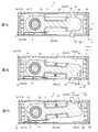
図1は、本発明の実施の形態1に係る振動アクチュエーターを示す外観斜視図であり、図2は、振動アクチュエーターのカバーを外した状態を示す斜視図であり、図3は、振動アクチュエーターの可動体を示す分解斜視図である。[Overall configuration of vibration actuator 1]
FIG. 1 is an external perspective view showing the vibration actuator according to the first embodiment of the present invention, FIG. 2 is a perspective view showing a state in which the cover of the vibration actuator is removed, and FIG. 3 is a movable view of the vibration actuator. It is an exploded perspective view which shows the body.
本実施の形態では、直交座標系(X,Y,Z)を使用して説明する。後述する図(変形例1、実施の形態2の説明に供する図も含む)においても共通の直交座標系(X,Y,Z)で示している。以下において、振動アクチュエーター1の幅、奥行き、高さは、それぞれ、X方向、Y方向、Z方向の長さである。本実施の形態の振動アクチュエーターは、便宜上、図1〜図4では、Z方向を横方向に向けて配置した状態で図示され、Z方向(Z方向プラス側及びZ方向マイナス側)を振動方向(揺動方向)として説明する。また、本実施の形態における「可動体の側方」は、可動体を中心としてZ方向に直交する放射方向を意味し、本実施の形態では、可動体を中心としたX方向、−X方向、Y方向を意味する。また、Z方向プラス側を上側、Z方向マイナス側を下側としてもよい。 In this embodiment, a Cartesian coordinate system (X, Y, Z) will be used for description. It is also shown in a common Cartesian coordinate system (X, Y, Z) in the figures described later (including the figures used for the description of the first and second embodiments). In the following, the width, depth, and height of the vibrating
振動アクチュエーター1は、ゲーム機器GC、スマートフォンSP及びウェアラブル端末W等の電子機器(図21〜図23参照)に振動発生源として実装され、電子機器の振動機能を実現する。振動アクチュエーター1は、例えば、振動することで、ユーザーに対して操作感や臨場感を与えたり、着信を通知したりする場合に駆動する。振動アクチュエーター1は、例えば、電子機器において、ユーザーに接触する振動伝達面とXY面が平行となるように実装される。振動伝達面は、ゲームコントローラーの場合では、ユーザーの指等の体表面が接触する面(操作ボタン等が配置される表面或いは、他の指等が当接する裏面)スマートフォンやタブレット端末の場合はタッチパネル面である。また、摺動伝達面は、ユーザーの服や腕などに装着されるウェアラブル端末では、服や腕に接触する外面(図23に示す内周面208)である。 The
図1〜図4に示すように、振動アクチュエーター1は、可動体10、軸部50及び固定体20を備える。可動体10は、軸部50を介して固定体20に支持される。本実施の形態では、可動体10は、一端側で挿通する軸部50を支点として他端側が往復動(揺動)つまり、振動するように、固定体20に回動自在に支持されている。 As shown in FIGS. 1 to 4, the
可動体10は、駆動時に振動(揺動)する部分である。本実施の形態では、可動体10は、コイル12と、コイル12が巻回されるコア14とを有し、固定体20はマグネット(第1マグネット30及び第2マグネット40)を有する。 The
振動アクチュエーター1の可動体10及び固定体20の構成は、通電されるコイル12と第2マグネット40との協働により可動体10を往復動させて振動を発生させる構成であれば、どのように構成されていてもよい。振動アクチュエーター1において、第1マグネット30は無くてもよく、また、可動体10を固定体20に対して揺動させる構成でなくてもよい。また、コイル12を固体体20に設け、マグネット(第2マグネット40)を可動体10に設けた構成としてもよい。いずれの構成の場合でも、マグネット(第2マグネット40)及びコイルのうち可動体における一方と、固定体における他方とは、一方の他方に対する移動軌跡の全位置、或いは、一部において吸引磁力が変化するように構成される。 The configuration of the
可動体10は、固定体20に対して、マグネット(第1マグネット30及び第2マグネット40)の吸引力による磁気バネにより、可動自在に支持される。本実施の形態では、可動体10は、マグネット(第1マグネット30及び第2マグネット40)と、コイル12及びコア14とにより構成される磁気バネにより固定体20に対して軸部50周りに可動自在に支持されている。 The
本実施の形態では、磁気バネは、コイル12が巻回されたコア14と、マグネットとして第1マグネット30及び第2マグネット40とを有する構成としたが、主に、コイル12、コア14及び第2マグネット40により構成されるものとして説明する。 In the present embodiment, the magnetic spring has a
可動体10は、コイル12に異なる周波数の電流が通電されてもそれぞれに対応して好適に振動可能な広い設定周波数で可動する。コイル12に駆動信号で入力される周波数を入力周波数とも称する。本実施の形態では、後述するが、振動を発生する周波数帯が広くなっており、広い周波数帯において、設定された振動あるいはその振動よりも強いG値を発揮し、つまり、可動体10は、広い周波数帯で強く振動可能である。なお、G値は、加速度であり、振動の強さを意味する。可動体10、つまり、振動アクチュエーター1の周波数特性についての詳細は後述する。 The
可動体10は、板ばね、コイルばね等の部品としての弾性支持部材を用いることなく、固定体20に対して振動自在に支持されている。これにより、弾性支持部の部品点数を削減することができる。更に、振動アクチュエーター1の筐体において、弾性支持部のための配置スペースを確保する必要が無く、振動アクチュエーター1自体の一層のコンパクト化を図ることができる。 The
また、弾性支持部材としての板ばね、コイルバネ等の機械バネは、耐久試験などの信頼性試験において、共振により可動体を振動させ続けた際に最も負担が掛かるので、一番初めに機能不全となる。これに対して、アクチュエーター1は、磁気バネのみで共振を構成し、機械バネを使用していないので、機械的損失がほとんどなく、アクチュエーター1を半永久的に使用できる。本実施の形態のアクチュエーター1は、磁気バネを使用した全てのレゾナントデバイス、つまり、共振を利用した振動デバイスに適用可能となって言える。 In addition, mechanical springs such as leaf springs and coil springs as elastic support members are the most burdensome when the movable body continues to vibrate due to resonance in reliability tests such as durability tests, so it is said to be dysfunctional at the very beginning. Become. On the other hand, since the
[軸部50]
図5は、振動アクチュエーターの要部構成を示す平断面図である。
軸部50は、可動体10を固定体20に対して揺動による振動自在に支持する。軸部50は、非磁性体および磁性体のどちらでもよく、本実施の形態では、例えば、SUS420J2等の磁性体により構成されている。[Shaft 50]
FIG. 5 is a plan sectional view showing a main configuration of the vibration actuator.
The
軸部50は、ベースプレート22と、ベースプレート22に固定されるケース24の底面部241との間に架設されている。ケース24の底面部241と可動体10との間には軸部50に外装されるワッシャ282が介在し、ベースプレート22と可動体10の間には、軸部50に外装されるワッシャ284が介在する。これらワッシャ282、284により、軸部50は、可動体10を固定体20に対して円滑に揺動するように支持している。 The
[可動体10]
可動体10は、コイル12と、コイル12が巻回されるコア14と、軸受けであるブッシュ(軸受け)16と、コイルボビン18(ボビン分割体181、182)と、を有する。
コア14は、コイル12のコイル軸方向に延在する長尺の磁性体により形成されている。コア14は、ベースプレート22およびケース24の底面部241との間に、それぞれから所定間隔を空けて配置されている。ここで所定間隔とは、可動体10の可動範囲を構成する空間である。[Movable body 10]
The
The
コア14は、コイル12の通電により磁化される磁性体であることが好ましい。コア14は、フェライトコアであってもよい。また、コア14は、電磁ステンレス、焼結材、MIM(メタルインジェクションモールド)材、積層鋼板、電気亜鉛メッキ鋼板(SECC)等により構成されてもよい。 The
コア14は、軸部50の軸方向と直交する方向に延在して設けられている。コア14は、一端側に挿通された軸部50を介して、回動自在に設けられ、他端部(先端部)144が自由端部として固定体20(具体的には、ベースプレート22の面部およびケース24の底面部241に対して平行とする方向、ここではZ方向に振動する。 The
コア14は、一端部(基端部)142に貫通孔が形成され、貫通孔には、軸部50が挿通されるブッシュ16が嵌め込まれている。 A through hole is formed in one end (base end) 142 of the core 14, and a
コア14の一端部142と他端部144との間には、コイルボビン18(ボビン分割体181、182)が外装され、コイルボビン18にはコイル12が巻回されている。可動体10は、本実施の形態では、コア14にコイルボビン18を介してコイル12が巻回されることにより直方体状に形成される。
コア14は、コイル12が通電されて励磁されることにより、両端部、つまり、一端部142と他端部(先端部)144とにおいてコイルの軸方向に位置する端面142a、端面(先端部に含まれる)144aの厚み方向、つまり、振動方向(Z方向)の長さの中心が、磁極の中心となる。A coil bobbin 18 (bobbin split
When the
また、コア14の一端部142及び他端部144は、それぞれの端面142a、144aの振動方向の長さが短くなるように、振動方向で離間する角部が面取りされている。
これにより、コア14の一端部142及び他端部144は、端面142a、144a側に向かって、振動方向の厚みが薄くなっており、それぞれを通る磁束が、磁極の中心に集中するように構成されている。特に、他端部144の端面144aは、他端部144において振動方向で離間する角部に、傾斜面1442、1444(図5参照)を設けることにより、傾斜面1442、1444(図5参照)が無い状態の場合よりも、他端部411の端面144aの面積が小さくなっている。これにより、可動体10は、後述する規準位置から揺動した際の最大揺動角度を大きくしている。先端部144の端面144aの面積を変更することにより、磁気バネ定数(バネ定数)を変更し、振動可能な周波数帯を変更できる。
本実施の形態では、傾斜面1442、1444の形成角度により、後述する磁気バネ定数を変更することができる。
可動体10では、可動体10の磁極の中心がコイル12のコイル軸上に配置されている。Further, the one
As a result, the thickness of one
In the present embodiment, the magnetic spring constant described later can be changed depending on the formation angles of the
In the
ブッシュ16は、筒状であり、軸部50が挿通され、可動体10を、軸部50を中心に回動可能にする。ブッシュ16は、焼結金属等の金属、樹脂等どのような材料により形成されてもよいが、軸部50が磁性体である場合は、非磁性材料で形成されることが好ましい。また、軸部50が非磁性体であれば、ブッシュ16は磁性体により形成されてもよい。 The
軸部50或いはブッシュ16の一方が非磁性体であれば、コア14を通る磁束が、軸部50とブッシュ16との間を通ることがなく、双方の間で、磁気吸引力の発生に起因する摩擦の増加が発生することがない。すなわち、ブッシュ16とブッシュ16を挿通する軸部50との間に磁気吸引力による摩擦が発生することがなく、可動体10の回動を円滑に行うことができる。 If either the
例えば、軸部50に耐久性を有する磁性シャフト(例えば、SUS420J2)を用いるとともに、ブッシュ16として銅系の焼結軸受を用いて振動アクチュエーター1を形成する。この構成によれば、可動体10の駆動において不要な磁気吸引力を抑制し、かつ、低摩擦にて可動体10を保持することができる。すなわち、可動体10の駆動による摩耗を抑制し、信頼性の高い振動アクチュエーター1を実現できる。 For example, a durable magnetic shaft (for example, SUS420J2) is used for the
コア14の一端部142には、フレキシブル基板15の一端部152が固定され、コイル12の両端部はフレキシブル基板15の回路に接続されている。 One
フレキシブル基板15は、コイル12に電力を供給するものあり、本実施の形態では可動体10と固定体20とを接続するように配設されている。 The
フレキシブル基板15は、可動体10のコイル12に接続される一端部152と、固定体20側に固定される他端部154と、一端部152と他端部154との間に、一端側からコイル12に導通する少なくとも1つ以上の可撓性を有する湾曲部156とを有する、
湾曲部156は、一端部152と他端部154との間に介設され可動体10の振動に追従して変形する可撓性を有する。湾曲部156は、軸部50の軸方向と直交する方向に可撓する。The
The
コイル12は、通電されて可動体10を可動するコイルであり、通電されてコア14の一端部142、他端部144を磁化する。コイル12は、通電方向が切り替えられることにより、コア14の両端部(一端部142及び他端部144)の極性を変更する。 The
コイルボビン18は、ボビン分割体181、182により構成される。ボビン分割体181、182のそれぞれは、コア14において一端部142と他端部144との間の部位を周方向で囲むように外装して固定される。ボビン分割体181、182は、例えば、ポリアミド樹脂、液晶ポリマー、ポリフェニレンサルファイド樹脂(PPS樹脂)等の樹脂材料により構成されてもよい。 The
[固定体20]
固定体20は、軸部50を介して可動体10を回動自在に支持する。
固定体20は、マグネット(第1マグネット30及び第2マグネット40)の他、ベースプレート22及びケース24を有する。固定体20は、更に、クッション材(緩衝部)60を有する。[Fixed body 20]
The fixed
The fixed
ベースプレート22は、鋼板等の板状材(本実施の形態では矩形板)により形成される。ベースプレート22は、本実施の形態では、振動アクチュエーター1の一側面を構成する。なお、ベースプレート22は、ケース24が被さるように取り付けられ、ベースプレート22は、ケース24とともに、可動体10を可動可能に収容する筐体を構成する。筐体は、本実施の形態では、中空の直方体状に形成される。筐体において長手方向で一端部側には、可動体10の振動方向と直交する方向に沿って軸部50が固定されている。ケース24の底面部241は、振動アクチュエーター1の一側面に対向する他側面を構成する。 The
ベースプレート22上には、一端側に、軸固定部23を介して軸部50が立設されている。ベースプレート22上には、可動体10が離間して対向配置されている。また、ベースプレート22の一端部には、可動体10の一端側に対向して、第1マグネット30が配置され、ベースプレート22の他端部には、可動体10の他端側に対向して第2マグネット40が配置されている。 On the
ケース24は、ベースプレート22に対向する可動体10を覆うようにベースプレート22に固定される。
ケース24において、ベースプレート22と幅方向(X方向)で対向する底面部241には、図示しない軸固定部を介して、軸部50の他端が固定されている。The
In the
ケース24は、ベースプレート22側で開口する箱形状(本実施の形態では角箱状)に形成されている。ケース24は、底面部241、両側面部242、243、一端面部244及び他端面部245を有する。底面部241は、ベースプレート22との間で軸部50が架設される。両側面部242、243は、可動体10の振動方向(ここではZ方向)で離間して対向配置される。一端面部244及び他端面部245は、可動体10の延在方向(ここでは奥行き方向(Y方向))で離間する。 The
ベースプレート22にケース24が取り付けられることにより形成される筐体の寸法は特に制限されないが、本実施の形態では、幅(X方向)、奥行き(Y方向)、高さ(Z方向)のうち、奥行きが最も長く、高さが最も短い直方体形状となるように構成されている。 The dimensions of the housing formed by attaching the
ケース24は、ベースプレート22とともに、導電性を有する材料、例えば、鋼板等の板状材(本実施の形態では矩形板)により形成されてもよい。これにより、ベースプレート22及びケース24は、電磁シールドとして機能できる。 The
また、ケース24の両側面部242、243には、他端部側のそれぞれに、振動する可動体10の自由端側が接触する緩衝部60(クッション材61、62)が設けられている。 Further, both
緩衝部60は、可動体10が振動した際に、可動体10の他端部が接触することにより、可動体10の振動を振動アクチュエーター1の筐体に伝達する(図7参照)。これにより、緩衝部60は、大きな振動を筐体に発生させることができる。
緩衝部60は、例えば、エラストマー、シリコーンゴム等のゴム、樹脂、又は多孔質弾性体(例えば、スポンジ)などの軟質材料により形成される。本実施の形態では緩衝部60は、筐体側である両側面部242、243に設けたクッション材61、62としている。緩衝部60は、可動体10側、例えば、可動体10の自由端部である他端部144に設けて、可動体10の振動時に、可動体10が緩衝部60で両側面部242、243に接触するようにしてもよい。緩衝部60が、エラストマーである場合、可動体10の駆動時において、可動体10のコア14の他端部144と、側面部242、243とが接触する際の音、或いは振動ノイズの発生を低減できる。When the
The
また、緩衝部60が、シリコーンゴムである場合、可動体10のコア14の他端部144と、側面部242、243とが接触する際の音、或いは振動ノイズの発生を低減できる。これに加えて、緩衝部60がシリコーンゴムである場合、内部に気泡を含むスポンジ状の材料により形成された場合のエラストマーと比較して、その厚みに個体差が発生することがない。よって、緩衝部60の厚みが所望の厚みとなるように、緩衝部60の厚さの管理を容易に行うことができ、緩衝部60としての特性の安定を確保できる。 Further, when the
マグネット(第1マグネット30及び第2マグネット40)は、コイル12との協働により、可動体10を可動する。マグネットは、可動体10に対する磁気吸引力により磁気バネとして機能する。本実施の形態では、コイル12が巻回されたコア14と磁気バネを構成し、可動体10を可動自在に支持している。
マグネットは、コイル12に対してコイル12の軸方向で対向するように配置される。
マグネットは、本実施の形態では、コア14の一端部に対してコイル12の軸方向で離間して対向する第1マグネット30と、コア14の他端部に対してコイル12の軸方向で離間して対向する第2マグネット40とを有する。The magnets (
The magnets are arranged so as to face the
In the present embodiment, the magnets are separated from the
第1マグネット30及び第2マグネット40は、それぞれコア14(可動体10)に向けて着磁されている。本実施の形態では、第1マグネット30及び第2マグネット40の着磁方向は、コイル12の軸方向と平行である。第1マグネット30及び第2マグネット40は、それぞれコア14に対向する側の面として、軸部50の延在方向と直交する方向(可動体10の振動方向に相当)で並ぶ異なる2極の磁極を有する。 The
この磁極の境界、つまり、磁極の切り替わり位置に対向して、可動体10のコア14の中心(ここでは、コイル12の軸であり、コイル12が励磁された際の磁極の中心に相当)が同じ軸上に位置するように配置される。なお、磁極の切り替わり位置と、可動体10のコア14の中心とは、真正面で対向するような同じ軸線上に配置されておらず、多少のずれがあってもよい。この位置は、コイル12が巻回されたコア14と、マグネットとによる磁気バネを用いて可動体10が可動する際の規準位置となりうる位置である。本実施の形態では、コア14の先端部(端面144a)が2極の磁極の切替位置に対向する位置を基準位置とし、この基準位置に位置する可動体10の状態を基準状態と称する。マグネット(特に、第2マグネット40)は、コア14を吸引して磁気バネとして機能し、コア14の先端部を、常時、基準位置に位置するように付勢する。 The center of the
第1マグネット30及び第2マグネット40の双方の磁極の極性は、可動体10のコイル12が励磁されることにより発生するトルクが可動体10の同一回転方向に発生するように着磁されている。 The polarities of the magnetic poles of both the
例えば、図5に示すように、第1マグネット30及び第2マグネット40において、側面部242側に配置され、且つ、可動体10に対向するそれぞれの磁極301、401は、同極(図5では、S極)となるように形成されている。また、第1マグネット30及び第2マグネット40において、側面部243側に配置され、且つ、可動体10に対向するそれぞれの磁極302、402は、同極(図5では、N極)となるように形成されている。 For example, as shown in FIG. 5, in the
第1マグネット30の裏面には、バックヨーク32が貼設され、第1マグネット30の第2マグネット40の裏面には、バックヨーク42が貼設されており、第1マグネット30、第2マグネット40のそれぞれの磁気吸引力の向上が図られている。 A
第1マグネット30及び第2マグネット40において、側面部242側にS極、側面部243側にN極となるように着磁されている場合、コイル12の非通電時においては、図5に示すように第1及び第2マグネット30、40では、それぞれN極から出射し、S極に入射する磁束が形成される。非通電時では、コイル12が巻回されるコア14の一端部142は、第1マグネット30のS極と極の双方に吸引され、異なる磁極301,302(S極とN極)の切替位置で保持される。また、コア14の他端部144は、第2マグネット40のS極とN極の双方に吸引され、異なる磁極401,402(S極とN極)の切替位置で保持される。第1マグネット30及び第2マグネット40は、可動体10の磁性体であるコア14とともに、コア14との間に発生する磁気吸引力により磁気バネとして機能し、可動体10を可動自在に支持している。 When the
側面部243には、一端部152でコイル12に接続されるフレキシブル基板15の他端部154が固定されている。 The
フレキシブル基板15は、コイル12に接続される一端部152が可動体10の一端部に固定され、他端部154が固定体20、ここでは、側面部243に固定されている。他端部154は、一部を筐体の外面に露出させて側面部243に固定されている。可動体10の可動時において、軸部50の近傍は、可動体10の他端側の部位よりも可動範囲が小さい。これにより、軸部50の近傍に配置されるフレキシブル基板15では、湾曲部156に掛かる荷重が小さくなる。このように、フレキシブル基板15は、軸部50近傍で固定されているので、フレキシブル基板15の変位を最小限にすることができ、可動時に発生する応力による断線を防止できる。 In the
なお、フレキシブル基板15において、一端部152と可動体10との間に、例えば、弾性接着剤又は弾性接着テープ等の弾性部材を介在させて、振動時の衝撃を弾性部材が吸収するようにしてもよい。 In the
[振動アクチュエーター1の磁気回路]
図6は、振動アクチュエーターの磁気回路を示す図である。図7A〜図7Cは、可動体の動作を示す縦断面図である。図7Aは、非通電時における可動体10の状態(基準状態)を示し、図7Bは、可動体10の先端部側、つまり、コア14の他端部144側から振動アクチュエーター1を見て時計回りに、コイル12に通電したときの可動体10の状態を示す。また、図7Cは、可動体10の先端部側、つまり、コア14の他端部144側から振動アクチュエーター1を見て反時計回りに、コイル12に通電したときの可動体10の状態を示す。[Magnetic circuit of vibration actuator 1]
FIG. 6 is a diagram showing a magnetic circuit of a vibrating actuator. 7A to 7C are vertical cross-sectional views showing the operation of the movable body. FIG. 7A shows a state (reference state) of the
振動アクチュエーター1において、可動体10は、固定体20のベースプレート22とケース24との間に、軸部50を介して一端側を支持された状態で配置されている。加えて、マグネット(第1マグネット30及び第2マグネット40)は、可動体10のコイル12の軸方向で、異なる2極の磁極をコイル12側に向けて、コイル12が巻回されるコア14の両端部(一端部142、他端部144)に対向して配置されている。第1マグネット30の磁極301と、第2マグネット40の磁極401とは同極であり、第1マグネット30の磁極302と、第2マグネット40の磁極402とは同極である。 In the vibrating
第1マグネット30及び第2マグネット40の各マグネットでは、異なる2極の磁極301、302、401、402は、それぞれ軸部50の軸方向と直交する方向に並べて配置されている。 In each of the magnets of the
可動体10では、フレキシブル基板15を介して電源供給部(例えば、図20〜図22に示す駆動制御部203)からコイル12が通電されることにより、Z方向、つまり、ケース24の側面部242、243に対して接離する方向に往復動する。具体的には、可動体10の他端部が揺動する。これにより、振動アクチュエーター1の振動出力が、振動アクチュエーター1を有する電子機器のユーザーに伝達される。 In the
振動アクチュエーター1では、図6に示す磁気回路が形成される。 In the
振動アクチュエーター1においてコイル12への非通電時(基準状態)では、コイルボビン18を介してコイル12が巻回されるコア14の両端部(一端部142、他端部144)は、それぞれ、第1マグネット30及び第2マグネット40にそれぞれ吸引される。 When the
コア14は、両端部(一端部142、他端部144)のぞれぞれの軸方向と直交する長さ(振動方向の長さ)の中心が、マグネットの磁極の切替位置に対向する位置に位置している。なお、両端部(一端部142、他端部144)のぞれぞれの軸方向と直交する長さ(振動方向の長さ)の中心は、コイル12の軸と同一軸上に位置している。 The
具体的には、コア14の一端部142は、第1マグネット30の異なる磁極301、302の双方の磁気吸引力により吸引され、磁極301、302の切替位置で保持される。 Specifically, one
また、コア14の他端部(自由端部)144は、第2マグネット40の異なる磁極401、402の双方の磁気吸引力により吸引され、磁極401、402の切替位置で保持される。 Further, the other end (free end) 144 of the
このように可動体10は、固定体20の第1マグネット30及び第2マグネット40とで構成する磁気バネのみで、基準状態で保持される。 As described above, the
振動アクチュエーター1において、コイル12は、第1マグネット30及び第2マグネット40からの磁束に沿うように、且つ、離間して配置されている。 In the
この構成により、図6及び図7Bに示すように通電が行われると、コイル12に流れる電流により、コア14の両端部(一端部142、他端部144)はそれぞれ異なる磁極となるように磁化される。具体的には、一端部142はN極、他端部144はS極に磁化される。 With this configuration, when energization is performed as shown in FIGS. 6 and 7B, both ends (one
これにより、一端部142は、第1マグネット30の磁極301に吸引され、第1マグネット30の磁極302とは反発して推力fが発生し、推力f方向に移動する。一方、他端部144は、第2マグネット40の磁極401とは反発し、第2マグネット40の磁極402に吸引され、推力−F方向に移動する。 As a result, the one
図7Bに示すように、コイル12への通電により、振動アクチュエーター1では、軸部50を挟んで位置する両端部(一端部142、他端部144)が、推力f、−F方向にそれぞれ移動することにより、同一回転方向である推力−Mが発生する。これにより、可動体10は、軸部50を中心に、推力−M方向に回転して、可動体10の他端部144が側面部243側に移動し、クッション材62を介して側面部243、つまり筐体に接触(具体的には衝突)し、筐体に振動を付与する。 As shown in FIG. 7B, by energizing the
また、コイル12の通電方向が逆方向に切り替わり、図7Cに示すように通電が行われると、それぞれ逆向きの推力−f、Fが発生する。具体的には、一端部142はS極、他端部144はN極に磁化される。これにより、一端部142は、第1マグネット30の磁極301とは反発し、第1マグネット30の磁極302に吸引され、推力−fが発生し、推力−f方向に移動する。一方、他端部144は、第2マグネット40の磁極401に吸引され、第2マグネット40の磁極402とは反発し、F方向に移動する。 Further, when the energization direction of the
図7C示すように、コイル12への通電により、振動アクチュエーター1では、軸部50を挟んで位置する両端部(一端部142、他端部144)が、推力−f、F方向にそれぞれ移動することにより、同一回転方向である推力Mが発生する。これにより、可動体10は、軸部50を中心に、推力M方向に回転して、可動体10の他端部144が側面部243とは反対側の側面部242側に移動し、クッション材61を介して側面部242、つまり筐体に接触(具体的には衝突)し、筐体に振動を付与する。 As shown in FIG. 7C, by energizing the
振動アクチュエーター1では、可動体10は、板ばね等の弾性部材を用いることなく、マグネット(第1マグネット30及び第2マグネット40)、コイル12及びコア14を用いた磁気ばねのみを用いて、固定体20に対して、軸部50を中心に振動(揺動)自在に支持されている。 In the vibrating
したがって、従来のように金属ばねにより可動体を振動自在に支持する振動アクチュエーターと異なり、金属ばね特有の不具合となる金属疲労や衝撃による破損を防ぐことができる。 Therefore, unlike the conventional vibrating actuator in which a movable body is oscillated by a metal spring, it is possible to prevent damage due to metal fatigue or impact, which is a defect peculiar to the metal spring.
また、軸部50は、可動体10の中心位置からずれた位置で、可動体10を回動自在に支持している。これにより、円筒形状の可動体を、回転軸を中心に回転駆動することにより振動を発生させる従来の振動アクチュエーターと異なり、錘を追加する等のように別途重心位置をずらす設計とする必要が無く、そのための部品の削減及びコストの削減を図ることができる。
重心位置をずらすための別部品を必要としないため、設計においてレイアウトの自由度が高く、設計サイズを大きくすることなく、小型でユーザーに十分な体感振動を与える振動アクチュエーターを実現できる。Further, the
Since no separate component is required to shift the position of the center of gravity, there is a high degree of freedom in layout in the design, and it is possible to realize a vibration actuator that is compact and gives the user sufficient perceived vibration without increasing the design size.
本実施の形態のアクチュエーター1では、ベースプレート22及びケース24とよりより構成される筐体は、直方体形状であり、可動体10は、短手方向(Z方向)に揺動して振動する。これにより、振動アクチュエーターを、矩形状のスイッチに適用する場合でも、スイッチ全体でムラなく振動させることができる。 In the
また、本実施の形態では、マグネットは、第1マグネット30及び第2マグネット40として、コア14の両側に配置され、それぞれの端部142、144で発生するトルクが、同一回転方向に発生するように、各々2極の磁極301、302、401、402が配置されている。コア14の両端部(一端部142、他端部144)の双方で、第1マグネット30及び第2マグネット40との間に磁気吸引力が発生する。これにより、第1マグネット30及び第2マグネット40とコイル12との協働により可動体10を可動させる際に、軸部50に加わる磁気吸引力による荷重が相殺される。よって、軸部50及びブッシュ16に掛かる負荷を低減でき、振動アクチュエーターとしての信頼性の向上を図ることができる。 Further, in the present embodiment, the magnets are arranged on both sides of the core 14 as the
また、可動体10は、筐体内で、筐体の側面部242,243に接触する。これにより、振動アクチュエーター1自体に直接的に振動伝達が可能となり、大きな振動を発生させることができる。また、可動体10が振動する際に、固定体20(筐体)に接触するため、振動量も一定となり、振動アクチュエーター1として安定した振動出力を実現できる。 Further, the
なお、可動体10の自由端部であるコア14の他端部144は、自由端側に向かってZ方向の厚みが薄くなるように形成されている。これにより、他端部144がクッション材61、62を介して接触する部位が、自由端側に向かってZ方向の厚みが同じ厚みである場合と比較して、揺動の際の可動域が広くなり、より大きな振動出力を確保できる。 The
また、振動アクチュエーター1によれば、可動体10とケース24の内壁面(側面部242、243)のうちの少なくとも一方(本実施の形態では側面部242、243)に、緩衝部60が設けられている。可動体10とケース24の内壁面(ここでは、側面部242、243)とは、緩衝部60(クッション材61、62)を介して接触する。緩衝部60は、可動体10が振動してベースプレート22又はケース24に接触する際の衝撃を緩和し、接触音や振動ノイズの発生を低減しつつ、ユーザーに振動を伝達することができる。また、振動する度に、可動体10は、緩衝部60を介してベースプレート22及びケース24に交互に接触(具体的には衝突)するので、振動出力が増幅される。これにより、実際の可動体10による振動出力よりも大きな振動出力を、ユーザーに体感させることができる。さらにベースプレート22はユーザーに装着される部材であるため、可動体10の振動はベースプレート22を介して直接的にユーザーに伝達されるので、ユーザーに更に大きな振動出力を体感させることができる。 Further, according to the
ここで、振動アクチュエーター1は、フレキシブル基板15を介して電源供給部(例えば、図21〜図23に示す駆動制御部203)からコイル12へ入力される交流波によって駆動される。つまり、コイル12の通電方向は周期的に切り替わり、可動体10にはZ方向プラス側の推力MとZ方向マイナス側の推力−Mが交互に作用する。これにより、可動体10の他端側は、YZ面内で円弧状に振動する。 Here, the
以下に、振動アクチュエーター1の駆動原理について簡単に説明する。本実施の形態の振動アクチュエーター1では、可動体10の慣性モーメントをJ[kg・m2]、磁気ばねのバネ定数(磁気バネ定数)をKspとした場合、可動体10は、固定体20に対して、下式(1)によって算出される共振周波数fr[Hz]で振動する。The driving principle of the

可動体10は、バネ−マス系の振動モデルにおけるマス部を構成するので、コイル12に可動体10の共振周波数frに等しい周波数の交流波が入力されると、可動体10は共振状態となる。すなわち、電源供給部(例えば、図21〜図23に示す駆動制御部203)からコイル12に対して、可動体10の共振周波数frと略等しい周波数の交流波を入力することにより、可動体10を効率良く振動させることができる。Since the
振動アクチュエーター1の駆動原理を示す運動方程式及び回路方程式を以下に示す。振動アクチュエーター1は、下式(2)で示す運動方程式及び下式(3)で示す回路方程式に基づいて駆動する。 The equation of motion and the circuit equation showing the driving principle of the
すなわち、振動アクチュエーター1における可動体10の慣性モーメントJ[kg・m2]、回転角度θ(t)[rad]、トルク定数Kt[N・m/A]、電流i(t)[A]、バネ定数Ksp[N・m/rad]、減衰係数D[N・m/(rad/s)]等は、式(2)を満たす範囲内で適宜変更できる。また、電圧e(t)[V]、抵抗R[Ω]、インダクタンスL[H]、逆起電力定数Ke[V/(rad/s)]は、式(3)を満たす範囲内で適宜変更できる。That is, the moment of inertia J [kg · m2 ] of the
このように、振動アクチュエーター1では、可動体10の慣性モーメントJと磁気ばねのバネ定数Kspにより決まる共振周波数frに対応する交流波によりコイル12への通電を行った場合に、効率的に大きな振動出力を得ることができる。Thus, the
<変形例1>
図8は、本実施の形態1の振動アクチュエーター1の変形例としての振動アクチュエーター1Aの磁気回路構成を示す平断面図である。なお、図8では、便宜上、コイル12を、可動体10の先端部側、つまり、コア14の他端部144側から振動アクチュエーター1を見て時計回りに通電したときの可動体10の状態を示す。<Modification example 1>
FIG. 8 is a plan sectional view showing a magnetic circuit configuration of the vibrating
図8に示す振動アクチュエーター1Aでは、振動アクチュエーター1と比較して、第2マグネット40に代えて、第1マグネット30と同様に構成される第1マグネット30Aを有する。 The vibrating
すなわち、振動アクチュエーター1Aでは、振動アクチュエーター1の構成において、コア14の両端部(一端部142、他端部144)のそれぞれに、コイル12の軸方向で対向して配置されるマグネットを、第1マグネット30、30Aとしている。 That is, in the
振動アクチュエーター1Aでは、マグネットは、第1マグネット30、30Aとして、コア14の両側に配置され、それぞれの端部142、144で発生するトルクは、同一回転方向に発生しない。しかしながら、コア14では、一端部142側で、非磁性体であるブッシュ16に軸部50が挿通されているため、コイル12が通電されることにより発生する磁束が、軸部50を通過しない分、一端部142の磁極を著しく励磁することがない。一端部142側では、一端部142と第1マグネット30とによるトルク発生には大きく寄与することなく、磁気ばねとして機能する。 In the
したがって、コイル12の通電により可動体10を揺動により振動させる際に、一端部142と第1マグネット30とにより発生するトルクは、他端部144と第1マグネット30Aとにより発生するトルクを阻害しない。これにより、振動アクチュエーター1Aによれば、振動アクチュエーター1と同様に、従来のように金属ばねにより可動体を振動自在に支持する振動アクチュエーターと異なり、金属ばね特有の不具合となる金属疲労や衝撃による破損を防ぐことができる。 Therefore, when the
<振動アクチュエーター1の共振周波数>
本実施の形態の振動アクチュエーター1では、可動体10は、コイル12、コア14及びマグネット(第1及び第2マグネット30、40のうち、特に、第2マグネット40)により構成される磁気バネにより、固定体20に対して移動可能に構成されている。
また、本実施の形態では、可動体10(コア14)の揺動中心が、可動体10(コア14)の揺動中心が、マグネット(特に、第2マグネット40)の磁極の切り替わり位置近傍に位置から、揺動が大きくなるにつれて引き合う磁力が弱くなるように構成されている。すなわち、振動アクチュエーター1では、コイル12が巻回されたコア14、つまり電磁石と、マグネット(永久磁石であり、特に第2マグネット40)との配置構造は、可動体10(コア14)が揺動中心の時に、最大磁力が発生するように構成されている。
これにより、可動体10(コア14)の第2マグネット40に対する揺動の軌道上の各位置において一部もしくは全部に対して第2マグネット40の吸引磁力が変化するように構成されている。<Resonance frequency of
In the
Further, in the present embodiment, the swing center of the movable body 10 (core 14) is located near the switching position of the magnetic poles of the magnet (particularly, the second magnet 40) with the swing center of the movable body 10 (core 14). From the position, it is configured so that the attractive magnetic force becomes weaker as the swing becomes larger. That is, in the vibrating
As a result, the attractive magnetic force of the
なお、このコイル12が巻回されたコア14と第2マグネット40との配置構造は、揺動中心より揺動最大幅の方が、磁力が強くなるような配置構造としてもよい。すなわち、磁気バネのバネ定数Kspが、コア14の先端部が,マグネット(第2マグネット40)に対して基準位置(切り替わり位置)に位置するときが最も小さく、揺動して基準位置から離間するにつれて大きくなるように、コア14及びマグネット(第2マグネット40)を配置してもよい。この構成の場合、例えば、第2マグネット40の磁極の切り替わり位置が、揺動中心に位置するコア14よりも最も遠く、コア14の揺動最大幅に位置した際に、第2マグネット40の磁極が最も接近する。具体的には、揺動中心に位置するコア14に対して、第2マグネット40の形状を、磁極の切り替わり位置が最も遠い位置になるように、逆V字状に構成して、揺動するコア14に対向して配置する等により実現される。The arrangement structure of the
本実施の形態の振動アクチュエーター1では、Z方向に配置された平板状の第2マグネット40の磁極面に対して、基準状態からコア14が揺動により円弧状の軌跡を描いて傾斜することにより、コア14と第2マグネット40の磁極面との間のギャップ(図7B、Cに示すギャップG1、G2)が変化する。これにより、振動アクチュエーターでは、コア14を含む可動体10は、バネ定数Kspひいては、共振周波数fr[Hz]が変化しながら揺動する。In the
図9は、本実施の形態の振動アクチュエーター1の磁気バネのバネ定数Kspを示す図である。なお、振動アクチュエーター1Aも、振動アクチュエーター1と同様の磁気バネ、周波数特性(共振周波数)を有する。FIG. 9 is a diagram showinga spring constant K sp of the magnetic spring of the
可動体10が基準状態にあるとき、コア14の先端部(端面144a)の中心が、第2マグネット40の磁極の切り替わり位置とともに、Y方向に沿う略同一平面(同一平面も含む)上に位置する。このとき、可動体10の第2マグネット40に対する揺動角度を0°とする(図7A参照)。 When the
振動アクチュエーター1では、図9のグラフQ1、Q2に示すように、可動体10が揺動角度0°の位置から揺動して、揺動角度0°の位置から離間するにつれて、バネ定数Kspが小さくなるように設定されている。なお、グラフQ0は、共振周波数が一つである線形構造におけるバネ定数を示し、グラフQ1、2の比較対象として示す。すなわち、振動アクチュエーター1では、磁気バネのバネ定数Kspが、コア14の先端部がマグネット(第2マグネット40)に対して基準位置(切り替わり位置)に位置するときが最も大きく、揺動して基準位置から離間するにつれて小さくなるように、コア14及びマグネット(第2マグネット40)は配置されている。In the
具体的には、コイル12が巻回されたコア14の端面(先端部)144aの中心とマグネット(第2マグネット40)との間のギャップ(G1、G2)が、揺動角度0°のとき(G0)最も小さく、最大揺動角度位置に位置するときに最も大きくなる(G1=G2>G0)ように、コア14とマグネット(第2マグネット40)は設けられている。 Specifically, when the gap (G1, G2) between the center of the end surface (tip) 144a of the
例えば、揺動角度0°のときのバネ定数Kspを100%とした場合に対して、最大揺動角度時のときのバネ定数Kspを90%以下の値とすることが好ましい。すなわち、最大揺動角度時のときのバネ定数Kspは、コア14の先端部144aが基準位置に位置するときのバネ定数Kspを1とした場合の0.9以下であることが好ましい。さらに、揺動角度0°のときのバネ定数Kspを100%、つまり、コア14の先端部144aが基準位置に位置するときのバネ定数を1とした場合に対して、最大揺動角度時のときのバネ定数Kspは、0.9〜0.95であることが好ましい。さらに好ましくは、揺動角度0°のときのバネ定数Kspを100%とした場合に対して、最大揺動角度時のときのバネ定数Kspを、70%以下の値(グラフQ1参照)とすることが好ましい。更には50%以下の値であり、更には50%以下で40%以上であることが好ましい(グラフQ2参照)。特に、揺動角度0°のときのバネ定数Kspを100%とした場合、最大揺動角度時のときのバネ定数Ksp、つまり、コア14の先端部144aが基準位置から揺動した最大揺動角度位置に位置したときのバネ定数は、コア14の先端部144aが基準位置に位置するときのバネ定数を1とした場合の0.3以上0.6以下であることが好ましい。これらにより、より効果的にバネ定数Kspを変化させて、可動体10を円滑に移動させることができる。For example, it is preferable that the spring constant K sp at the maximum swing angle is 90% or less asopposed to the case where the spring constant K sp at the swing angle of 0 ° is 100%. That is, the spring constant Ksp at the maximum swing angle is preferably 0.9 or lesswhen the spring constant K sp when the
振動アクチュエーター1では、可動体10の揺動角度0°時のバネ定数Kspと、可動体10の最大揺動時のバネ定数Kspの差が大きい方が好ましい。
本実施の形態の振動アクチュエーター1は、グラフQ2で示すバネ定数Kspとなるように構成されている。In the
The
図10は、本発明の実施形態の振動アクチュエーター1の周波数特性を示す図である。なお、図10及び図11から図13で示すG値において、最大値は、一般的には、共振時(最大振幅時)において出力される値であり、G値が大きければ、触感として強い振動を付与することができ、G値が小さければ、触感として弱い振動を付与することができる。 FIG. 10 is a diagram showing the frequency characteristics of the
図10に示すように、振動アクチュエーター1は、コイル12が巻回されたコア14とマグネットとの磁気バネにより、可動体10が揺動可能に設けられており、左右非対称な非線形の周波数特性を有する。 As shown in FIG. 10, in the vibrating
振動アクチュエーター1の周波数特性は、所定の低周波数(低い入力周波数)で急激に立ち上がり、設定G値を超えて、立ち上がった周波数の最大のG値に到達した後、急激に下がることなく、なだらかに傾斜しつつ下がる。図10に示す周波数波形Q01、Q11、Q21は、図9のバネ定数KspのグラフQ0、Q1、Q2にそれぞれ対応する。The frequency characteristic of the vibrating
振動アクチュエーター1は、バネ定数(グラフQ2で示す)により、周波数波形Q21で示す共振周波数を有する。なお、振動アクチュエーター1は、バネ定数(グラフQ1で示す)による周波数波形Q11で示す共振周波数を有するようにしてもよい。 The
図10は、本発明の実施の形態1に係る振動アクチュエーターの周波数特性を示す図であり、周波数特性として、振動アクチュエーター1の周波数波形(Q11、Q21)を示す。周波数波形(Q11、Q21)は、設定したG値以上のG値を出力する周波数帯(W1、W2)を有する。この周波数帯(W1、W2)は、線形特性を有する共振周波数と比較して、設定G値以上のG値を出力する周波数帯が広い。 FIG. 10 is a diagram showing the frequency characteristics of the vibrating actuator according to the first embodiment of the present invention, and shows the frequency waveforms (Q11, Q21) of the vibrating
本実施の形態では、振動アクチュエーター1は、グラフQ2で示すバネ定数Kspを有し、コア14とマグネット(第1マグネット30、第2マグネット40)とが配置され、周波数波形Q21で示す共振周波数を有する。In the present embodiment, the
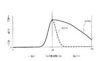
図11は、本実施の形態1の周波数特性としての図10の周波数波形Q21の拡大図である。 FIG. 11 is an enlarged view of the frequency waveform Q21 of FIG. 10 as the frequency characteristic of the first embodiment.
図11に示す振動アクチュエーター1の周波数波形Q21は、入力された低周波数でG値が低い値から急激に立ち上がる立ち上がり周波数f1から入力周波数が高くなるにつれて、立ち上がり周波数f1よりもG値の高い共振点f0に至り、徐々に低下する特性を有する。なお、立ち上がり周波数f1より左側の帯域は、設定G値以上のG値を出力できないため、使用できない。 The frequency waveform Q21 of the
周波数波形Q21で示す周波数特性により、左右対称の線形構造の共振周波数(図10の周波数波形Q01参照)と比較して、設定G値以上の広い周波数帯W2を有する。なお、振動アクチュエーター1の周波数特性は、周波数帯W2を含む周波数波形Q21で示されるものとしたが、周波数帯W1を含む周波数波形Q11で示されるものであってもよい。 Due to the frequency characteristics shown by the frequency waveform Q21, it has a wide frequency band W2 equal to or larger than the set G value as compared with the resonance frequency of the symmetrical linear structure (see the frequency waveform Q01 in FIG. 10). Although the frequency characteristic of the
周波数帯W1、W2は、コア14とマグネット(特に第2マグネット40)との間のギャップ(図7B、CのG1、G2参照)により異なる大きさの周波数帯となっている。共振可能な周波数帯W1、W2は、線形構造のバネによる周波数(グラフQ0)の周波数帯W0よりも広い帯域となっている。 The frequency bands W1 and W2 have different sizes depending on the gap between the core 14 and the magnet (particularly the second magnet 40) (see G1 and G2 in FIGS. 7B and 7B). The resonable frequency bands W1 and W2 are wider than the frequency band W0 of the frequency (graph Q0) due to the spring having a linear structure.
また、周波数帯W2では、基準状態時、つまり、揺動角度0°時のバネ定数と最大揺動時のバネ定数との差が、周波数帯W1よりも大きい。これにより、周波数帯W2は、周波数帯W1よりも広い帯域を有し、異なる入力周波数で共振できる。 Further, in the frequency band W2, the difference between the spring constant in the reference state, that is, when the swing angle is 0 ° and the spring constant when the swing angle is maximum swing is larger than that in the frequency band W1. As a result, the frequency band W2 has a wider band than the frequency band W1 and can resonate at different input frequencies.
振動アクチュエーター1の周波数特性は、磁気バネを用いて可動体10を可動させるため左右非対称となる。 The frequency characteristic of the
図12を用いて、振動アクチュエーター1の周波数特性(共振周波数)が、左右非対称な構成であることについて説明する。 It will be described with reference to FIG. 12 that the frequency characteristic (resonance frequency) of the
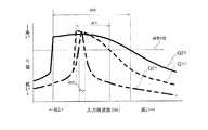
図12は、本発明の実施の形態1に係る振動アクチュエーターの周波数特性の説明に供する図であり、周波数特性波形の非線形部分とバネ定数との関係を示す図である。なお、図12に示す周波数波形は、周波数波形Q11を示す。周波数波形Q21は、周波数波形Q11と比較して、ギャップの差異以外は同様に構成されるので、ここでは、周波数波形Q11を用いて説明する。 FIG. 12 is a diagram for explaining the frequency characteristics of the vibration actuator according to the first embodiment of the present invention, and is a diagram showing the relationship between the non-linear portion of the frequency characteristic waveform and the spring constant. The frequency waveform shown in FIG. 12 shows the frequency waveform Q11. Since the frequency waveform Q21 is configured in the same manner as the frequency waveform Q11 except for the difference in the gap, the frequency waveform Q11 will be described here.
振動アクチュエーター1では、低周波数側から駆動信号(最低周波数の信号、入力周波数に相当する)を付与する(駆動電流を通電する)と、揺動最大時で共振動作を始める(周波数波形Q110で示す)。次いで、この周波数波形Q110で示す最低周波数よりも大きい周波数の信号(入力周波数)を付与していく。なお、図12では、高い周波数で順次、付与していく入力周波数を共振周波数(破線)で示す。 In the
付与される信号(入力周波数)は、高周波になるにつれて、振幅が小さくなるので、ギャップが狭くなっていくこと同義となり、付与された信号(入力周波数の共振周波数)は上がる(周波数波形Q111の最大G値の位置Q111a参照)。具体的には、振動アクチュエーターの周波数が、周波数波形Q110で示す線形構造の周波数のままであれば、G値は、最大振幅位置よりも大きく下がった位置Q111bにあるはずが、下がりきらずに、最低周波数の最大G値近傍に位置し位置Q111aで示すG値が出力される。これを繰り返し、順次高い周波数の信号を付与していくと、曲線Q112で示すG値が出力される。 Since the amplitude of the applied signal (input frequency) decreases as the frequency increases, it is synonymous with narrowing the gap, and the applied signal (resonance frequency of the input frequency) increases (maximum frequency waveform Q111). See G value position Q111a). Specifically, if the frequency of the vibrating actuator remains the frequency of the linear structure shown in the frequency waveform Q110, the G value should be at the position Q111b, which is much lower than the maximum amplitude position, but it does not fall completely and is at least. It is located near the maximum G value of the frequency and the G value indicated by the position Q111a is output. When this is repeated and signals of high frequencies are sequentially applied, the G value shown by the curve Q112 is output.
入力される駆動信号が、高周波になるにつれ振幅が小さくなると、図12に示すように、バネ定数Kspが上がり、共振周波数も高く急激に下がることが無くなだらかな曲線Q112で下がっていく。これにより、振動アクチュエーターは、図13で示す非線形構造の周波数特性を有するものとなる。When the amplitude of the input drive signal decreases as the frequency increases, as shown in FIG. 12, the spring constant Ksp increases, the resonance frequency also increases, and the resonance frequency decreases on a gentle curve Q112 without suddenly decreasing. As a result, the vibrating actuator has the frequency characteristics of the non-linear structure shown in FIG.
この曲線Q112は、揺動角度0°時のバネ定数と最大揺動時のバネ定数の差が大きい程、横軸方向における異なる周波数間の距離が大きくすることができるので、より大きな駆動周波帯(例えば図10の周波数帯W2)とすることができる。すなわち、曲線Q112は、揺動角度おけるコア14とマグネット(特に第2マグネット40)との間のギャップ調整することにより、立ち上がり周波数a0からの傾斜を略水平に変更でき、図10で示す周波数波形Q21で示す共振周波数特性となる。 In this curve Q112, the larger the difference between the spring constant when the swing angle is 0 ° and the spring constant when the maximum swing is, the larger the distance between different frequencies in the horizontal axis direction can be, so that a larger drive frequency band can be obtained. (For example, the frequency band W2 in FIG. 10) can be used. That is, the curve Q112 can change the inclination from the rising frequency a0 substantially horizontally by adjusting the gap between the core 14 at the swing angle and the magnet (particularly the second magnet 40), and the frequency waveform shown in FIG. This is the resonance frequency characteristic shown in Q21.
本実施の形態によれば、振動アクチュエーター1において、共振して設定G値以上のG値を出力可能な駆動信号の周波数の範囲を広くしている、つまり、共振周波数の帯域が広くワイドバンド化された状態となっている。 According to the present embodiment, in the
これにより、使用環境温度が異なり、図14に示すように、使用環境温度としての温度と反比例して変化する周波数の信号(入力周波数)が入力されても、信号に応じて確実に振動を発生することができる。例えば、使用環境温度により、図10で示す周波数波形Q21の使用可能な周波数帯W2において、最大G値(共振周波数)を含む領域が使用できなくなっても、更に右側で設定G値を出力する周波数までの高周波数帯域を使用することができる。また、図15に示すように、部品寸法の公差、組立の際の公差等により、設定されたギャップにバラツキがある場合でも、これに対応して、好適に共振して振動を発生させることができる。
このように、本実施の形態によれば、部品点数の低減化及び小型化を図るとともに、振動発生可能な周波数帯を広くすることができ、異なる周波数の電流が通電されても、それぞれに応じてユーザーに十分な体感振動を与えることができる。As a result, the operating environment temperature is different, and as shown in FIG. 14, even if a signal (input frequency) having a frequency that changes in inverse proportion to the temperature as the operating environment temperature is input, vibration is reliably generated according to the signal. can do. For example, even if the region including the maximum G value (resonance frequency) cannot be used in the usable frequency band W2 of the frequency waveform Q21 shown in FIG. 10 due to the operating environment temperature, the frequency at which the set G value is output on the right side. High frequency bands up to can be used. Further, as shown in FIG. 15, even if there are variations in the set gap due to the tolerance of component dimensions, the tolerance at the time of assembly, etc., it is possible to appropriately resonate and generate vibration in response to the variation. can.
As described above, according to the present embodiment, the number of parts can be reduced and the size can be reduced, and the frequency band in which vibration can be generated can be widened. It is possible to give the user sufficient perceived vibration.
<実施の形態2>
図16は、本発明の実施の形態2に係る振動アクチュエーター1Bのカバーを外した状態を示す斜視図であり、図17は、振動アクチュエーターの分解図であり、図18は、振動アクチュエーター1Bの要部構成を示す平断面図である。また、図19は、振動アクチュエーター1Bの磁気回路を示す図であり、図20は、可動体の動作を示す縦断面図である。図20Aは、非通電時における可動体10の状態(基準状態)を示し、図20Bは、可動体10の先端部側、つまり、コア14の他端部144側から振動アクチュエーター1Bを見て時計回りに、コイル12に通電したときの可動体10の状態を示す。図20Cは、可動体10の先端部側、つまり、コア14の他端部144側から振動アクチュエーター1Bを見て反時計回りに、コイル12に通電したときの可動体10の状態を示す。なお、振動アクチュエーター1Bは、振動アクチュエーター1と同様の磁気バネ、周波数特性(共振周波数)を有する。<
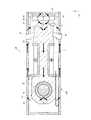
16 is a perspective view showing a state in which the cover of the vibrating
図16〜図20に示す実施の形態に係る振動アクチュエーター1Bは、振動アクチュエーター1と比較して、第1マグネット30及びバックヨーク32を省略したものである。 The vibrating
よって以下では、アクチュエーター1と異なる構成について説明し、アクチュエーター1における構成要素と同様の作用効果を有するものについては、同名称及び同符号を付して説明は省略する。 Therefore, in the following, a configuration different from that of the
振動アクチュエーター1Bは、振動アクチュエーター1と同様に、スマートフォン等の電子機器(図21〜図23参照)に振動発生源として実装され、電子機器の振動機能を実現する。 Like the
図16〜図20に示す振動アクチュエーター1Bは、可動体10、軸部50及び固定体20Bを備える。可動体10は、軸部50を介して固定体20Bに支持される。本実施の形態では、可動体10は、一端側で挿通する軸部50を支点として他端側が往復動するように、固定体20Bに回動自在に支持されている。 The vibrating
可動体10は、駆動時に振動(揺動)する部分である。本実施の形態では、可動体10は、コイル12と、コイル12が巻回されるコア14とを有し、固定体20Bはマグネットとしてコア14の他端部144と対向して配置される第2マグネット40を有する。 The
可動体10は、固定体20Bに対して、第2マグネット40の吸引力による磁気バネにより、可動自在に支持される。 The
本実施の形態では、可動体10は、第2マグネット40と、コイル12及びコア14とにより構成される磁気バネにより固定体20Bに対して軸部50周りに可動自在に支持されている。 In the present embodiment, the
可動体10は、コイル12と、コイル12が巻回されるコア14と、軸受けであるブッシュ(軸受け)16と、ボビン分割体181、182からなるコイルボビンと、を有する。また、固定体20Bは、第2マグネット40の他、ベースプレート22及びケース24を有する。固定体20Bは、固定体20と同様に、緩衝部(クッション材)60を有する。 The
第2マグネット40は、コイル12との協働により、可動体10を可動する。第2マグネット40は、可動体10に対する磁気吸引力により磁気バネとして機能する。本実施の形態では、コイル12が巻回されたコア14と磁気バネを構成し、可動体10を可動自在に支持している。 The
第2マグネット40は、コア14の他端部に対してコイル12の軸方向で離間して対向する。第2マグネット40は、コア14の他端部144に向けて着磁されている。第2マグネット40は、実施の形態1と同様に、コア14に対向する側の面として、軸部50の延在方向と直交する方向(可動体10の振動方向に相当)で並ぶ異なる2極の磁極401、402を有する。 The
この磁極401、402の境界、つまり、磁極401、402の切り替わり位置に対向して、可動体10のコア14の中心(ここでは、コイル12の軸であり、コイル12が励磁された際の磁極の中心に相当)が位置するように配置される。 Opposing the boundary between the
例えば、図17及び図18に示すように、第2マグネット40において、側面部242側に配置され、且つ、可動体10に対向する磁極401は、S極で着磁され、側面部243側に配置され、且つ、可動体10に対向する磁極402は、N極で着磁されている。 For example, as shown in FIGS. 17 and 18, in the
第1マグネット30の裏面には、バックヨーク32が貼設され、第1マグネット30の第2マグネット40の裏面には、バックヨーク42が貼設されており、それぞれのマグネット30、40の磁気吸引力の向上が図られている。 A
コイル12の非通電時においては、図20に示すように第2マグネット40では、N極から出射し、S極に入射する磁束が形成される。非通電時では、コア14の他端部144は、第2マグネット40のS極とN極の双方に吸引され、異なる磁極401,402(S極とN極)の切替位置で保持される。すなわち、第2マグネット40は、可動体10の磁性体であるコア14とともに、コア14との間に発生する磁気吸引力により磁気バネとして機能し、可動体10を可動自在に支持している。なお、側面部243には、一端部152でコイル12に接続されるフレキシブル基板15の他端部154が固定されている。 When the
振動アクチュエーター1Bでは、コイル12への非通電時(基準状態)では、コイル12が巻回されるコア14の他端部144は、第2マグネット40の異なる磁極401、402の双方の磁気吸引力により吸引され、磁極401、402の切替位置で保持される。 In the
可動体10におけるコア14の他端部(自由端部)144は、固定体20Bの第2マグネット40とで構成する磁気バネのみで、基準状態で保持される。なお、他端部144の軸方向と直交する長さ(振動方向の長さ)の中心は、コイル12の軸と同一軸上に位置している。 The other end (free end) 144 of the core 14 in the
振動アクチュエーター1Bにおいて、図19及び図20Bに示すように通電が行われると、コイル12に流れる電流により、コア14の他端部144はS極に磁化される。 When the
他端部144は、第2マグネット40の磁極401とは反発し、第2マグネット40の磁極402に吸引され、−F方向に移動する。 The
図20Bに示すように、コイル12への通電により、振動アクチュエーター1Bの他端部144が、−F方向に移動することにより、同一回転方向である推力−Mが発生する。これにより、可動体10は、推力−M方向に回転して、可動体10の他端部144が側面部243側に移動し、クッション材62を介して側面部243、つまり筐体に接触(具体的には衝突)し、筐体に振動を付与する。 As shown in FIG. 20B, when the
また、コイル12の通電方向が逆方向に切り替わり、図20Cに示すように通電が行われると、可動体10に対して逆向きの推力Fが発生する。具体的には、他端部144はN極に磁化され、第2マグネット40の磁極401に吸引され、第2マグネット40の磁極402とは反発し、F方向に移動する。 Further, when the energization direction of the
図20C示すように、コイル12への通電により、振動アクチュエーター1Bの他端部144が、F方向に移動し、側面部243とは反対側の側面部242側に移動する。そして、他端部144は、クッション材61を介して側面部242、つまり筐体に接触(具体的には衝突)し、筐体に振動を付与する。 As shown in FIG. 20C, when the
振動アクチュエーター1Bでは、振動アクチュエーター1と同様に、可動体10は、板ばね等の弾性部材を用いることなく、第2マグネット40、コイル12及びコア14を用いた磁気ばねのみを用いて、固定体20Bに対して、軸部50を中心に揺動により振動自在に支持されている。したがって、従来のように金属ばねにより可動体を振動自在に支持する振動アクチュエーターと異なり、金属ばね特有の不具合となる金属疲労や衝撃による破損を防ぐことができる。また、軸部50は、可動体10の中心位置からずれた位置で、可動体10を回動自在に支持しているので、実施形態1と同様の作用効果を得ることができる。 In the vibrating
<振動アクチュエーターを実装する電子機器>
図21から図23は、振動アクチュエーターを実装する電子機器の一例を示す図である。図21は、振動アクチュエーターをゲームコントローラーGCに実装した例を示し、図22は、振動アクチュエーターを携帯端末としてのスマートフォンSPに実装した例を示し、図23は、振動アクチュエーターをウェアラブル端末Wに実装した例を示す。<Electronic equipment that mounts a vibration actuator>
21 to 23 are views showing an example of an electronic device on which a vibration actuator is mounted. FIG. 21 shows an example in which the vibration actuator is mounted on the game controller GC, FIG. 22 shows an example in which the vibration actuator is mounted on the smartphone SP as a mobile terminal, and FIG. 23 shows an example in which the vibration actuator is mounted on the wearable terminal W. An example is shown.
ゲームコントローラーGCは、例えば、無線通信によりゲーム機本体に接続され、ユーザーが握ったり把持したりすることにより使用される。ゲームコントローラーGCは、ここでは矩形板状を有し、ユーザーが両手でゲームコントローラーGCの左右側を掴み操作するものとしている。 The game controller GC is connected to the game machine main body by wireless communication, for example, and is used by being grasped or grasped by the user. Here, the game controller GC has a rectangular plate shape, and the user grasps and operates the left and right sides of the game controller GC with both hands.
ゲームコントローラーGCは、振動により、ゲーム機本体からの指令をユーザーに通知する。なお、ゲームコントローラーGCは、図示しないが、指令通知以外の機能、例えば、ゲーム機本体に対する入力操作部を備える。 The game controller GC notifies the user of a command from the game machine main body by vibration. Although not shown, the game controller GC includes functions other than command notification, for example, an input operation unit for the game machine main body.
スマートフォンSPは、例えば、携帯電話やスマートフォン等の携帯通信端末である。スマートフォンSPは、振動により、外部の通信装置からの着信をユーザーに通知するとともに、スマートフォンSPの各機能(例えば、操作感や臨場感を与える機能)を実現する。 The smartphone SP is, for example, a mobile communication terminal such as a mobile phone or a smartphone. The smartphone SP notifies the user of an incoming call from an external communication device by vibration, and realizes each function of the smartphone SP (for example, a function that gives a feeling of operation and a sense of presence).
ウェアラブル端末Wは、ユーザーが身につけて使用するものである。ウェアラブル端末Wは、ここではリング形状を有し、ユーザーの指に装着される。ウェアラブル端末Wは、無線通信により情報通信端末(例えば、携帯電話)に接続される。ウェアラブル端末Wは、振動により、情報通信端末における電話やメールの着信をユーザーに通知する。なお、ウェアラブル端末Wは、着信通知以外の機能(例えば、情報通信端末に対する入力操作)を備えていてもよい。 The wearable terminal W is worn and used by the user. The wearable terminal W has a ring shape here and is worn on the user's finger. The wearable terminal W is connected to an information communication terminal (for example, a mobile phone) by wireless communication. The wearable terminal W vibrates to notify the user of an incoming call or e-mail on the information communication terminal. The wearable terminal W may have a function other than the incoming call notification (for example, an input operation to the information communication terminal).
図21〜図23に示すように、ゲームコントローラーGC、スマートフォンSP及びウェアラブル端末W等の電子機器は、それぞれ、通信部201、処理部202、駆動制御部203、及び駆動部としての振動アクチュエーター100A、100B、100C、100Dを有する。振動アクチュエーター100A、100B、100C、100Dは、振動アクチュエーター1、1A、1Bのいずれかのアクチュエーターである。なお、ゲームコントローラーGCでは、複数の振動アクチュエーター100A、100Bが実装される。 As shown in FIGS. 21 to 23, electronic devices such as a game controller GC, a smartphone SP, and a wearable terminal W have a
ゲームコントローラーGC、スマートフォンSP及びウェアラブル端末Wにおいて、振動アクチュエーター100A、100B、100C、100Dは、例えば、端末の主面と振動アクチュエーター100A、100B、100C、100Dの振動方向と直交する面、ここではケース24の側面部242、243が平行となるように実装される。電子機器の主面とは、ユーザーの体表面に接触する面であり、本実施の形態では、ユーザーの体表面に接触して振動を伝達する振動伝達面を意味する。 In the game controller GC, the smartphone SP, and the wearable terminal W, the
具体的には、ゲームコントローラーGCでは、操作するユーザーの指先、指の腹、手の平等が接触する面、或いは、操作部が設けられた面と、振動方向が直交するように振動アクチュエーター100A、100Bが実装される。また、スマートフォンSPの場合は、表示画面(タッチパネル面)と振動方向が直交するように振動アクチュエーター100Cが実装される。ウェアラブル端末Wの場合は、リング状の筐体の内周面208が主面(振動伝達面)であり、内周面208とXY面が略平行(平行も含む)となるように、振動アクチュエーター1が実装される。これにより、ゲームコントローラーGC、スマートフォンSP及びウェアラブル端末Wの主面に対して垂直な方向の振動が、ユーザーに伝達される。 Specifically, in the game controller GC, the
通信部201は、外部の通信装置と無線通信により接続され、通信装置からの信号を受信して処理部202に出力する。ゲームコントローラーGCの場合、外部の通信装置は、情報通信端末としてのゲーム機本体であり、Bluetooth(登録商標)等の近距離無線通信規格に従って通信が行われる。スマートフォンSPの場合、外部の通信装置は、例えば基地局であり、移動体通信規格に従って通信が行われる。また、ウェアラブル端末Wの場合、外部の通信装置は、例えば、携帯電話、スマートフォン、携帯型ゲーム端末等の情報通信端末であり、Bluetooth(登録商標)等の近距離無線通信規格に従って通信が行われる。 The
処理部202は、入力された信号を、変換回路部(図示省略)により振動アクチュエーター100A、100B、100C、100Dを駆動するための駆動信号に変換して駆動制御部203に出力する。なお、スマートフォンSPにおいては、処理部202は、通信部201から入力される信号の他、各種機能部(図示略、例えばタッチパネル等の操作部)から入力される信号に基づいて、駆動信号を生成する。 The
駆動制御部203は、振動アクチュエーター100A、100B、100C、100Dに接続されており、振動アクチュエーター100A、100B、100C、100Dを駆動するための回路が実装されている。駆動制御部203は、振動アクチュエーター100A、100B、100C、100Dに対して駆動信号を供給する。 The
振動アクチュエーター100A、100B、100C、100Dは、駆動制御部203からの駆動信号に従って駆動する。具体的には、振動アクチュエーター100A、100B、100C、100Dにおいて、可動体10は、ゲームコントローラーGC、スマートフォンSP及びウェアラブル端末Wの主面に直交する方向に振動する。 The
可動体10は、振動する度に、ケース24の側面部242、243にクッション材61、62を介して接触するので、可動体10の振動に伴うケース24の側面部242、243への衝撃、つまり、筐体への衝撃が、ダイレクトにユーザーに振動として伝達される。特に、ゲームコントローラーGCでは、複数の振動アクチュエーター100A、100Bが実装されているため、入力される駆動信号に応じて、複数の振動アクチュエーター100A、100Bのうちの一方、または双方を同時に駆動させることができる。 Each time the
ゲームコントローラーGC、スマートフォンSP及びウェアラブル端末Wに接触するユーザーの体表面には、体表面に垂直な方向の振動が伝達されるので、ユーザーに対して十分な体感振動を与えることができる。ゲームコントローラーGCでは、ユーザーに対する体感振動を、振動アクチュエーター100A、100Bのうちの一方、または双方で付与でき、少なくとも強弱の振動を選択的に付与するといった表現力の高い振動を付与できる。 Since the vibration in the direction perpendicular to the body surface is transmitted to the body surface of the user who comes into contact with the game controller GC, the smartphone SP, and the wearable terminal W, it is possible to give the user sufficient perceived vibration. In the game controller GC, the perceived vibration to the user can be applied by one or both of the
以上、本発明者によってなされた発明を実施の形態に基づいて具体的に説明したが、本発明は上記実施の形態に限定されるものではなく、その要旨を逸脱しない範囲で変更可能である。 Although the invention made by the present inventor has been specifically described above based on the embodiment, the present invention is not limited to the above embodiment and can be changed without departing from the gist thereof.
また、例えば、本発明に係る振動アクチュエーターは、実施の形態で示したゲームコントローラーGC、スマートフォンSP及びウェアラブル端末W以外の携帯機器(例えば、タブレットPCなどの携帯情報端末、携帯型ゲーム端末)に適用する場合に好適である。また、本実施の形態の振動アクチュエーター1、1A、1Bは、上述した携帯機器の他、振動を必要とする美顔マッサージ器等の電動理美容器具にも用いることができる。 Further, for example, the vibration actuator according to the present invention is applied to a portable device (for example, a portable information terminal such as a tablet PC, a portable game terminal) other than the game controller GC, the smartphone SP and the wearable terminal W shown in the embodiment. It is suitable when Further, the
今回開示された実施の形態はすべての点で例示であって制限的なものではないと考えられるべきである。本発明の範囲は上記した説明ではなくて特許請求の範囲によって示され、特許請求の範囲と均等の意味および範囲内でのすべての変更が含まれることが意図される。 It should be considered that the embodiments disclosed this time are exemplary in all respects and not restrictive. The scope of the present invention is shown by the scope of claims rather than the above description, and it is intended to include all modifications within the meaning and scope equivalent to the scope of claims.
本発明に係る振動アクチュエーターは、サイズを大きくすることなく、小型で、異なる周波数の電流が通電されても、それぞれに応じてユーザーに十分な体感振動を与えることができ、ゲームコントローラー、スマートフォン、或いはウェアラブル端末等の電子機器に搭載されるものとして有用である。 The vibration actuator according to the present invention is small and can give a user sufficient perceived vibration according to each of them even when currents of different frequencies are applied without increasing the size, and is a game controller, a smartphone, or a smartphone. It is useful as a device mounted on electronic devices such as wearable terminals.
1、1A、1B、100A、100B、100C、100D 振動アクチュエーター
10 可動体
12 コイル
14 コア
15 フレキシブル基板
16 ブッシュ
18 コイルボビン
20、20B 固定体
22 ベースプレート
23 軸固定部
24 ケース
30、30A 第1マグネット
32、42 バックヨーク
40 第2マグネット(マグネット)
50 軸部
60 緩衝部
61、62 クッション材
142、152 一端部
144 他端部(先端部)
154 他端部
142a 端面
144a 端面(先端部)
156 湾曲部
181、182 ボビン分割体
201 通信部
202 処理部
203 駆動制御部
208 内周面
241 底面部
242、243 側面部
244 一端面部
245 他端面部
282、284 ワッシャ
301、302、401、402 磁極1, 1A, 1B, 100A, 100B, 100C,
50
154
156
Claims (7)
Translated fromJapanese前記コアの先端部に対して離間して対向配置されるマグネットを有する固定体と、
前記可動体を前記コアの基端部側で回動自在に支持する軸部と、
を有し、
前記コイル、前記コア及び前記マグネットの協働により、前記コアの前記先端部が前記マグネットに対して前記軸部を中心に揺動して振動を発生する振動アクチュエーターであって、
前記マグネットは、前記可動体の揺動方向に並び、且つ、前記コアの先端部に対向する方向に着磁された2極の磁極を有し、前記2極の磁極の切替位置に対向する位置を基準位置として、前記コアの前記先端部が位置するように付勢する磁気バネを前記コアとともに構成し、
前記磁気バネのバネ定数が、前記コアの先端部が前記マグネットに対して基準位置に位置するときが最も大きく、揺動して前記基準位置から離間するにつれて小さくなるように、前記コア及び前記マグネットは配置されている、
振動アクチュエーター。A movable body with a core around which the coil is wound with the tip exposed,
A fixed body having a magnet arranged so as to be separated from the tip of the core,
A shaft portion that rotatably supports the movable body on the base end side of the core, and
Have,
A vibration actuator in which the tip portion of the core swings with respect to the magnet about the shaft portion to generate vibration by the cooperation of the coil, the core, and the magnet.
The magnet has a two-pole magnetic pole aligned in the swing direction of the movable body and magnetized in a direction facing the tip of the core, and a position facing the switching position of the two-pole magnetic pole. A magnetic spring is configured together with the core to urge the tip of the core to be positioned with the above as a reference position.
The core and the magnet have a spring constant that is greatest when the tip of the core is located at a reference position with respect to the magnet and decreases as it swings away from the reference position. Is placed,
Vibration actuator.
前記コアの先端部に対して離間して対向配置されるマグネットを有する固定体と、
前記可動体を前記コアの基端部側で回動自在に支持する軸部と、
を有し、
前記コイル、前記コア及び前記マグネットの協働により、前記コアの前記先端部が前記マグネットに対して前記軸部を中心に揺動して振動を発生する振動アクチュエーターであって、
前記マグネットは、前記可動体の揺動方向に並び、且つ、前記コアの先端部に対向する方向に着磁された2極の磁極を有し、前記2極の磁極の切替位置に対向する位置を基準位置として、前記コアの前記先端部が位置するように付勢する磁気バネを前記コアとともに構成し、
前記磁気バネのバネ定数が、前記コアの先端部が前記マグネットに対して基準位置に位置するときが最も小さく、揺動して前記基準位置から離間するにつれて大きくなるように、前記コア及び前記マグネットは配置されている、
振動アクチュエーター。A movable body with a core around which the coil is wound with the tip exposed,
A fixed body having a magnet arranged so as to be separated from the tip of the core,
A shaft portion that rotatably supports the movable body on the base end side of the core, and
Have,
A vibration actuator in which the tip portion of the core swings with respect to the magnet about the shaft portion to generate vibration by the cooperation of the coil, the core, and the magnet.
The magnet has a two-pole magnetic pole aligned in the swing direction of the movable body and magnetized in a direction facing the tip of the core, and a position facing the switching position of the two-pole magnetic pole. A magnetic spring is configured together with the core to urge the tip of the core to be positioned with the above as a reference position.
The core and the magnet so that the spring constant of the magnetic spring is the smallest when the tip of the core is located at the reference position with respect to the magnet and increases as it swings away from the reference position. Is placed,
Vibration actuator.
請求項1記載の振動アクチュエーター。The spring constant when the tip of the core is located at the maximum swing angle position where it swings from the reference position is the case where the spring constant when the tip of the core is located at the reference position is 1. Is less than 0.9
The vibration actuator according to claim 1.
請求項3記載の振動アクチュエーター。The spring constant when the tip of the core is located at the maximum swing angle position where it swings from the reference position is the case where the spring constant when the tip of the core is located at the reference position is 1. Is 0.9 to 0.95.
The vibration actuator according to claim 3.
請求項3記載の振動アクチュエーター。The spring constant when the tip of the core is located at the maximum swing angle position where it swings from the reference position is the case where the spring constant when the tip of the core is located at the reference position is 1. 0.3 or more and 0.6 or less
The vibration actuator according to claim 3.
低周波数側から立ちあがる共振周波数の共振点は、立ちあがった際の周波数よりも高い周波数である、
請求項1記載の振動アクチュエーター。The frequency characteristics of the magnetic spring are
The resonance point of the resonance frequency rising from the low frequency side is a frequency higher than the frequency when rising.
The vibration actuator according to claim 1.
電子機器。The vibration actuator according to any one of claims 1 to 6 is mounted.
Electronics.
Priority Applications (4)
| Application Number | Priority Date | Filing Date | Title |
|---|---|---|---|
| JP2020004739AJP7533871B2 (en) | 2020-01-15 | 2020-01-15 | Vibration actuator and electronic device |
| CN202110035575.7ACN113131707A (en) | 2020-01-15 | 2021-01-12 | Vibration actuator and electronic device |
| EP21151564.8AEP3852253A1 (en) | 2020-01-15 | 2021-01-14 | Vibration actuator and electronic apparatus |
| US17/148,623US11949310B2 (en) | 2020-01-15 | 2021-01-14 | Vibration actuator with movable body with tip part of the core oscillating and a shaft part supporting the movable body on a side of a base |
Applications Claiming Priority (1)
| Application Number | Priority Date | Filing Date | Title |
|---|---|---|---|
| JP2020004739AJP7533871B2 (en) | 2020-01-15 | 2020-01-15 | Vibration actuator and electronic device |
Publications (2)
| Publication Number | Publication Date |
|---|---|
| JP2021109165Atrue JP2021109165A (en) | 2021-08-02 |
| JP7533871B2 JP7533871B2 (en) | 2024-08-14 |
Family
ID=74184443
Family Applications (1)
| Application Number | Title | Priority Date | Filing Date |
|---|---|---|---|
| JP2020004739AActiveJP7533871B2 (en) | 2020-01-15 | 2020-01-15 | Vibration actuator and electronic device |
Country Status (4)
| Country | Link |
|---|---|
| US (1) | US11949310B2 (en) |
| EP (1) | EP3852253A1 (en) |
| JP (1) | JP7533871B2 (en) |
| CN (1) | CN113131707A (en) |
Cited By (1)
| Publication number | Priority date | Publication date | Assignee | Title |
|---|---|---|---|---|
| US12323021B2 (en) | 2022-02-28 | 2025-06-03 | Seiko Epson Corporation | Vibration generation device, vibration reduction device, and electronic apparatus |
Families Citing this family (4)
| Publication number | Priority date | Publication date | Assignee | Title |
|---|---|---|---|---|
| US20210257896A1 (en)* | 2020-02-17 | 2021-08-19 | Dan Haronian | Movement and Vibration energy harvesting |
| WO2022046969A1 (en)* | 2020-08-26 | 2022-03-03 | Propitious Technologies, Llc | Magnified linear power generation system |
| US11936269B2 (en)* | 2021-09-22 | 2024-03-19 | Apple Inc. | Haptic engine based on angular resonant actuator with pivot axis and mass center that differ |
| AU2024206608A1 (en)* | 2023-01-04 | 2025-07-17 | Wepower Technologies Llc | Trip mechanism based energy generator for electrical energy generation |
Citations (11)
| Publication number | Priority date | Publication date | Assignee | Title |
|---|---|---|---|---|
| JPH02193562A (en)* | 1988-03-28 | 1990-07-31 | Mitsubishi Kasei Corp | Actuator |
| JP2004202424A (en)* | 2002-12-26 | 2004-07-22 | Namiki Precision Jewel Co Ltd | Vibrator and portable terminal device equipped with this vibrator |
| CN1875537A (en)* | 2003-10-29 | 2006-12-06 | 布劳恩股份有限公司 | Drive unit for generating an oscillatory motion for electrical small-scale units |
| JP2007111619A (en)* | 2005-10-19 | 2007-05-10 | Alps Electric Co Ltd | Vibration generation device |
| JP2010221101A (en)* | 2009-03-23 | 2010-10-07 | Citizen Holdings Co Ltd | Vibration generator, and touch panel device provided with the same |
| JP2010260043A (en)* | 2009-05-04 | 2010-11-18 | Samsung Electro-Mechanics Co Ltd | Linear vibrator |
| JP2013010074A (en)* | 2011-06-29 | 2013-01-17 | Minebea Motor Manufacturing Corp | Vibration generator |
| JP2017538469A (en)* | 2014-11-21 | 2017-12-28 | コーニンクレッカ フィリップス エヌ ヴェKoninklijke Philips N.V. | Using a resonant system to automatically change the power (amplitude) of an oral care device when used in the oral cavity |
| WO2018117066A1 (en)* | 2016-12-20 | 2018-06-28 | ミツミ電機株式会社 | Vibration actuator, wearable terminal, and device with incoming notification function |
| WO2018131541A1 (en)* | 2017-01-13 | 2018-07-19 | ミツミ電機株式会社 | Vibratory actuator, wearable terminal, and incoming call notification function device |
| JP2019180168A (en)* | 2018-03-30 | 2019-10-17 | ミツミ電機株式会社 | Vibration actuator and vibration presentation device |
Family Cites Families (51)
| Publication number | Priority date | Publication date | Assignee | Title |
|---|---|---|---|---|
| JPS5249064Y2 (en) | 1971-12-20 | 1977-11-08 | ||
| US4135119A (en)* | 1977-03-23 | 1979-01-16 | General Scanning, Inc. | Limited rotation motor |
| US5180939A (en)* | 1992-02-24 | 1993-01-19 | Cummins Power Generation, Inc. | Mechanically commutated linear alternator |
| US5973422A (en)* | 1998-07-24 | 1999-10-26 | The Guitammer Company | Low frequency vibrator |
| US6405599B1 (en)* | 2000-01-13 | 2002-06-18 | Bose Corporation | Frictionless motor material testing |
| US7808236B1 (en)* | 2002-12-09 | 2010-10-05 | Ferro Solutions, Inc. | Energy harvester utilizing external magnetic field |
| US6853103B2 (en)* | 2003-01-31 | 2005-02-08 | Hiro Moriyasu | Low profile push-pull magnetic vibrating apparatus |
| US7569952B1 (en)* | 2003-04-18 | 2009-08-04 | Ferro Solutions, Inc. | High efficiency, inductive vibration energy harvester |
| JP4155101B2 (en)* | 2003-05-16 | 2008-09-24 | 松下電工株式会社 | Vibration type linear actuator and electric toothbrush using the same |
| DE10330978A1 (en)* | 2003-07-09 | 2005-02-10 | Braun Gmbh | Small electrical appliance with an electric motor for generating an oscillating movement |
| DE10355446A1 (en)* | 2003-11-27 | 2005-06-30 | Braun Gmbh | Electric motor for a small electrical appliance |
| JP3928619B2 (en)* | 2003-12-26 | 2007-06-13 | 松下電工株式会社 | Vibration type linear actuator |
| US7561014B2 (en)* | 2003-12-29 | 2009-07-14 | Honeywell International Inc. | Fast insertion means and method |
| US7199480B2 (en)* | 2004-04-15 | 2007-04-03 | Halliburton Energy Services, Inc. | Vibration based power generator |
| GB2425222B (en)* | 2005-04-12 | 2008-11-05 | Perpetuum Ltd | An electromechanical generator for converting mechanical vibrational energy into electrical energy |
| US7755227B2 (en)* | 2005-10-19 | 2010-07-13 | Alps Electric Co., Ltd. | Vibration generator |
| JP2007194907A (en)* | 2006-01-19 | 2007-08-02 | Citizen Electronics Co Ltd | Electric vibration transducer |
| GB2459269B (en)* | 2008-04-15 | 2010-09-29 | Perpetuum Ltd | An electromechanical generator for, and method of, converting mechanical vibrational energy into electrical energy |
| US20110133577A1 (en)* | 2008-08-18 | 2011-06-09 | In Ho Lee | Horizontal linear vibration device |
| KR20110085997A (en)* | 2008-10-22 | 2011-07-27 | 신포니아 테크놀로지 가부시끼가이샤 | Linear actuator |
| JP5176891B2 (en)* | 2008-11-14 | 2013-04-03 | ミツミ電機株式会社 | Actuator and electric toothbrush using the same |
| CN103038982B (en)* | 2009-01-27 | 2016-08-17 | 麻省理工学院 | Motor based on electrical permanent-magnet |
| EP2262084A1 (en)* | 2009-06-12 | 2010-12-15 | Braun GmbH | Electric motor for an electric appliance |
| JP4875133B2 (en)* | 2009-10-29 | 2012-02-15 | 日本電産コパル株式会社 | Vibration actuator |
| JP5724233B2 (en)* | 2010-07-12 | 2015-05-27 | シンフォニアテクノロジー株式会社 | Movable iron core type linear actuator |
| US8432049B2 (en)* | 2010-07-15 | 2013-04-30 | Sukho JUNG | Electrical generator |
| JP6039916B2 (en)* | 2012-04-23 | 2016-12-07 | 株式会社コガネイ | Potential measurement device |
| US9496778B2 (en)* | 2012-08-22 | 2016-11-15 | Ta Instruments-Waters L.L.C. | Electromagnetic motor |
| JP6245950B2 (en)* | 2013-11-11 | 2017-12-13 | 日本電産コパル株式会社 | Vibration actuator and portable information terminal |
| US20160006332A1 (en)* | 2014-07-07 | 2016-01-07 | Yen-Fu Liao | Reciprocating device for electric hair cutter |
| US9787167B2 (en)* | 2014-12-31 | 2017-10-10 | L'oreal | Oscillating motor for a personal care appliance |
| CN204392052U (en)* | 2015-01-16 | 2015-06-10 | 瑞声光电科技(常州)有限公司 | Vibrating motor |
| JP6558048B2 (en)* | 2015-04-24 | 2019-08-14 | ミツミ電機株式会社 | Power switch |
| CN110908320B (en)* | 2015-05-29 | 2022-05-10 | 广东易百珑智能科技有限公司 | Self-generating wireless switch and application thereof |
| US9843248B2 (en)* | 2015-06-04 | 2017-12-12 | David Deak, SR. | Rocker action electric generator |
| CN204947873U (en)* | 2015-07-31 | 2016-01-06 | 瑞声光电科技(常州)有限公司 | Vibrating motor |
| KR101621700B1 (en)* | 2015-09-01 | 2016-05-18 | 주식회사 하이소닉 | Haptic actuator |
| WO2017060940A1 (en)* | 2015-10-09 | 2017-04-13 | ミツミ電機株式会社 | Vibratory actuator, wearable terminal, and incoming call notification function device |
| CN110635658A (en)* | 2016-02-04 | 2019-12-31 | 广东易百珑智能科技有限公司 | High-power kinetic energy self-generating electric device |
| JP6908823B2 (en)* | 2016-12-27 | 2021-07-28 | ミツミ電機株式会社 | Power generators and electronic devices |
| CN108306454B (en)* | 2016-12-31 | 2021-12-17 | 武汉领普科技有限公司 | Power generation device |
| US10468928B2 (en)* | 2017-01-25 | 2019-11-05 | Shanghai Source Electrical Co., Ltd. | Magnetic balance structure and a magnetic balance linear vibration motor |
| JP6908830B2 (en)* | 2017-04-28 | 2021-07-28 | ミツミ電機株式会社 | Power generators and electronic devices |
| US11201530B2 (en)* | 2017-05-26 | 2021-12-14 | Purdue Research Foundation | Actuating device and method of making the same |
| JP7116293B2 (en)* | 2017-11-17 | 2022-08-10 | ミツミ電機株式会社 | Vibration actuators and portable devices |
| US11108316B2 (en)* | 2018-03-30 | 2021-08-31 | Nidec Sankyo Corporation | Actuator |
| JP7188851B2 (en)* | 2018-08-29 | 2022-12-13 | ミネベアミツミ株式会社 | Vibration actuator and portable electronic device provided with the same |
| US10644579B2 (en)* | 2018-08-31 | 2020-05-05 | George Nerubenko | Vibration energy harvesting damper |
| US11368079B2 (en)* | 2019-11-06 | 2022-06-21 | David Deak, SR. | Offset triggered cantilever actuated generator |
| WO2021152897A1 (en)* | 2020-01-30 | 2021-08-05 | 株式会社村田製作所 | Linear vibration motor, electronic device using same, vibrator, and method for manufacturing vibrator |
| JP7524917B2 (en)* | 2022-02-28 | 2024-07-30 | セイコーエプソン株式会社 | Vibration generating device, vibration reducing device and electronic device |
- 2020
- 2020-01-15JPJP2020004739Apatent/JP7533871B2/enactiveActive
- 2021
- 2021-01-12CNCN202110035575.7Apatent/CN113131707A/enactivePending
- 2021-01-14USUS17/148,623patent/US11949310B2/enactiveActive
- 2021-01-14EPEP21151564.8Apatent/EP3852253A1/enactivePending
Patent Citations (11)
| Publication number | Priority date | Publication date | Assignee | Title |
|---|---|---|---|---|
| JPH02193562A (en)* | 1988-03-28 | 1990-07-31 | Mitsubishi Kasei Corp | Actuator |
| JP2004202424A (en)* | 2002-12-26 | 2004-07-22 | Namiki Precision Jewel Co Ltd | Vibrator and portable terminal device equipped with this vibrator |
| CN1875537A (en)* | 2003-10-29 | 2006-12-06 | 布劳恩股份有限公司 | Drive unit for generating an oscillatory motion for electrical small-scale units |
| JP2007111619A (en)* | 2005-10-19 | 2007-05-10 | Alps Electric Co Ltd | Vibration generation device |
| JP2010221101A (en)* | 2009-03-23 | 2010-10-07 | Citizen Holdings Co Ltd | Vibration generator, and touch panel device provided with the same |
| JP2010260043A (en)* | 2009-05-04 | 2010-11-18 | Samsung Electro-Mechanics Co Ltd | Linear vibrator |
| JP2013010074A (en)* | 2011-06-29 | 2013-01-17 | Minebea Motor Manufacturing Corp | Vibration generator |
| JP2017538469A (en)* | 2014-11-21 | 2017-12-28 | コーニンクレッカ フィリップス エヌ ヴェKoninklijke Philips N.V. | Using a resonant system to automatically change the power (amplitude) of an oral care device when used in the oral cavity |
| WO2018117066A1 (en)* | 2016-12-20 | 2018-06-28 | ミツミ電機株式会社 | Vibration actuator, wearable terminal, and device with incoming notification function |
| WO2018131541A1 (en)* | 2017-01-13 | 2018-07-19 | ミツミ電機株式会社 | Vibratory actuator, wearable terminal, and incoming call notification function device |
| JP2019180168A (en)* | 2018-03-30 | 2019-10-17 | ミツミ電機株式会社 | Vibration actuator and vibration presentation device |
Cited By (1)
| Publication number | Priority date | Publication date | Assignee | Title |
|---|---|---|---|---|
| US12323021B2 (en) | 2022-02-28 | 2025-06-03 | Seiko Epson Corporation | Vibration generation device, vibration reduction device, and electronic apparatus |
Also Published As
| Publication number | Publication date |
|---|---|
| JP7533871B2 (en) | 2024-08-14 |
| CN113131707A (en) | 2021-07-16 |
| US20210218324A1 (en) | 2021-07-15 |
| US11949310B2 (en) | 2024-04-02 |
| EP3852253A1 (en) | 2021-07-21 |
Similar Documents
| Publication | Publication Date | Title |
|---|---|---|
| JP7248387B2 (en) | Vibration actuators and electronics | |
| CN110875680B (en) | Vibration actuator and portable electronic device provided with same | |
| JP7533871B2 (en) | Vibration actuator and electronic device | |
| JP7093013B2 (en) | Vibration actuators, wearable terminals and incoming call notification function devices | |
| KR101805473B1 (en) | Vibration module for portable terminal | |
| CN110365187A (en) | Vibration actuator and electronic device | |
| JP7057494B2 (en) | Vibration actuator and vibration presentation device | |
| JP2019097228A (en) | Vibration actuator and portable device | |
| JP2019097227A (en) | Vibration actuator and portable device | |
| JP2018118233A (en) | Vibration device, wearable terminal and incoming call notification function device | |
| JP2023023948A (en) | vibration actuator | |
| US11843297B2 (en) | Rotating vibration actuator with a weight and electronic apparatus | |
| JP7540271B2 (en) | Vibration actuator and electronic device | |
| JP7540272B2 (en) | Vibration actuator and electronic device | |
| WO2018008280A1 (en) | Linear vibration motor | |
| JP2024117594A (en) | Vibration actuator and electrical device | |
| JP2018051434A (en) | Linear vibration motor | |
| KR20180009600A (en) | Vibrator |
Legal Events
| Date | Code | Title | Description |
|---|---|---|---|
| A625 | Written request for application examination (by other person) | Free format text:JAPANESE INTERMEDIATE CODE: A625 Effective date:20221228 | |
| A977 | Report on retrieval | Free format text:JAPANESE INTERMEDIATE CODE: A971007 Effective date:20230828 | |
| A131 | Notification of reasons for refusal | Free format text:JAPANESE INTERMEDIATE CODE: A131 Effective date:20230912 | |
| A521 | Request for written amendment filed | Free format text:JAPANESE INTERMEDIATE CODE: A523 Effective date:20231110 | |
| A131 | Notification of reasons for refusal | Free format text:JAPANESE INTERMEDIATE CODE: A131 Effective date:20240206 | |
| A521 | Request for written amendment filed | Free format text:JAPANESE INTERMEDIATE CODE: A523 Effective date:20240408 | |
| TRDD | Decision of grant or rejection written | ||
| A01 | Written decision to grant a patent or to grant a registration (utility model) | Free format text:JAPANESE INTERMEDIATE CODE: A01 Effective date:20240702 | |
| A61 | First payment of annual fees (during grant procedure) | Free format text:JAPANESE INTERMEDIATE CODE: A61 Effective date:20240723 | |
| R150 | Certificate of patent or registration of utility model | Ref document number:7533871 Country of ref document:JP Free format text:JAPANESE INTERMEDIATE CODE: R150 |