JP2021106984A - Woven foldable catheter - Google Patents
Woven foldable catheterDownload PDFInfo
- Publication number
- JP2021106984A JP2021106984AJP2021075916AJP2021075916AJP2021106984AJP 2021106984 AJP2021106984 AJP 2021106984AJP 2021075916 AJP2021075916 AJP 2021075916AJP 2021075916 AJP2021075916 AJP 2021075916AJP 2021106984 AJP2021106984 AJP 2021106984A
- Authority
- JP
- Japan
- Prior art keywords
- catheter
- open
- filament
- distal end
- elastic
- Prior art date
- Legal status (The legal status is an assumption and is not a legal conclusion. Google has not performed a legal analysis and makes no representation as to the accuracy of the status listed.)
- Pending
Links
- 238000000034methodMethods0.000claimsdescription22
- 238000010586diagramMethods0.000abstractdescription5
- 239000000523sampleSubstances0.000description20
- 238000002679ablationMethods0.000description5
- 239000004744fabricSubstances0.000description3
- 210000000056organAnatomy0.000description3
- 230000000747cardiac effectEffects0.000description2
- 239000011810insulating materialSubstances0.000description2
- 238000012986modificationMethods0.000description2
- 230000004048modificationEffects0.000description2
- HLXZNVUGXRDIFK-UHFFFAOYSA-Nnickel titaniumChemical compound[Ti].[Ti].[Ti].[Ti].[Ti].[Ti].[Ti].[Ti].[Ti].[Ti].[Ti].[Ni].[Ni].[Ni].[Ni].[Ni].[Ni].[Ni].[Ni].[Ni].[Ni].[Ni].[Ni].[Ni].[Ni]HLXZNVUGXRDIFK-UHFFFAOYSA-N0.000description2
- 229910001000nickel titaniumInorganic materials0.000description2
- 206010001497AgitationDiseases0.000description1
- 238000004458analytical methodMethods0.000description1
- 238000003491arrayMethods0.000description1
- 230000015572biosynthetic processEffects0.000description1
- 230000006835compressionEffects0.000description1
- 238000007906compressionMethods0.000description1
- 229910003460diamondInorganic materials0.000description1
- 239000010432diamondSubstances0.000description1
- 230000000694effectsEffects0.000description1
- 208000014674injuryDiseases0.000description1
- 238000009940knittingMethods0.000description1
- 230000003287optical effectEffects0.000description1
- 230000008733traumaEffects0.000description1
Images


Classifications
- A—HUMAN NECESSITIES
- A61—MEDICAL OR VETERINARY SCIENCE; HYGIENE
- A61B—DIAGNOSIS; SURGERY; IDENTIFICATION
- A61B18/00—Surgical instruments, devices or methods for transferring non-mechanical forms of energy to or from the body
- A61B18/04—Surgical instruments, devices or methods for transferring non-mechanical forms of energy to or from the body by heating
- A61B18/12—Surgical instruments, devices or methods for transferring non-mechanical forms of energy to or from the body by heating by passing a current through the tissue to be heated, e.g. high-frequency current
- A61B18/14—Probes or electrodes therefor
- A61B18/1492—Probes or electrodes therefor having a flexible, catheter-like structure, e.g. for heart ablation
- A—HUMAN NECESSITIES
- A61—MEDICAL OR VETERINARY SCIENCE; HYGIENE
- A61M—DEVICES FOR INTRODUCING MEDIA INTO, OR ONTO, THE BODY; DEVICES FOR TRANSDUCING BODY MEDIA OR FOR TAKING MEDIA FROM THE BODY; DEVICES FOR PRODUCING OR ENDING SLEEP OR STUPOR
- A61M25/00—Catheters; Hollow probes
- A—HUMAN NECESSITIES
- A61—MEDICAL OR VETERINARY SCIENCE; HYGIENE
- A61B—DIAGNOSIS; SURGERY; IDENTIFICATION
- A61B5/00—Measuring for diagnostic purposes; Identification of persons
- A61B5/24—Detecting, measuring or recording bioelectric or biomagnetic signals of the body or parts thereof
- A61B5/25—Bioelectric electrodes therefor
- A61B5/279—Bioelectric electrodes therefor specially adapted for particular uses
- A61B5/28—Bioelectric electrodes therefor specially adapted for particular uses for electrocardiography [ECG]
- A61B5/283—Invasive
- A61B5/287—Holders for multiple electrodes, e.g. electrode catheters for electrophysiological study [EPS]
- A—HUMAN NECESSITIES
- A61—MEDICAL OR VETERINARY SCIENCE; HYGIENE
- A61B—DIAGNOSIS; SURGERY; IDENTIFICATION
- A61B5/00—Measuring for diagnostic purposes; Identification of persons
- A61B5/24—Detecting, measuring or recording bioelectric or biomagnetic signals of the body or parts thereof
- A61B5/316—Modalities, i.e. specific diagnostic methods
- A61B5/318—Heart-related electrical modalities, e.g. electrocardiography [ECG]
- A—HUMAN NECESSITIES
- A61—MEDICAL OR VETERINARY SCIENCE; HYGIENE
- A61B—DIAGNOSIS; SURGERY; IDENTIFICATION
- A61B5/00—Measuring for diagnostic purposes; Identification of persons
- A61B5/68—Arrangements of detecting, measuring or recording means, e.g. sensors, in relation to patient
- A61B5/6846—Arrangements of detecting, measuring or recording means, e.g. sensors, in relation to patient specially adapted to be brought in contact with an internal body part, i.e. invasive
- A61B5/6847—Arrangements of detecting, measuring or recording means, e.g. sensors, in relation to patient specially adapted to be brought in contact with an internal body part, i.e. invasive mounted on an invasive device
- A61B5/6852—Catheters
- A61B5/6856—Catheters with a distal loop
- A—HUMAN NECESSITIES
- A61—MEDICAL OR VETERINARY SCIENCE; HYGIENE
- A61B—DIAGNOSIS; SURGERY; IDENTIFICATION
- A61B5/00—Measuring for diagnostic purposes; Identification of persons
- A61B5/68—Arrangements of detecting, measuring or recording means, e.g. sensors, in relation to patient
- A61B5/6846—Arrangements of detecting, measuring or recording means, e.g. sensors, in relation to patient specially adapted to be brought in contact with an internal body part, i.e. invasive
- A61B5/6847—Arrangements of detecting, measuring or recording means, e.g. sensors, in relation to patient specially adapted to be brought in contact with an internal body part, i.e. invasive mounted on an invasive device
- A61B5/6852—Catheters
- A61B5/6859—Catheters with multiple distal splines
- B—PERFORMING OPERATIONS; TRANSPORTING
- B23—MACHINE TOOLS; METAL-WORKING NOT OTHERWISE PROVIDED FOR
- B23P—METAL-WORKING NOT OTHERWISE PROVIDED FOR; COMBINED OPERATIONS; UNIVERSAL MACHINE TOOLS
- B23P19/00—Machines for simply fitting together or separating metal parts or objects, or metal and non-metal parts, whether or not involving some deformation; Tools or devices therefor so far as not provided for in other classes
- B23P19/04—Machines for simply fitting together or separating metal parts or objects, or metal and non-metal parts, whether or not involving some deformation; Tools or devices therefor so far as not provided for in other classes for assembling or disassembling parts
- A—HUMAN NECESSITIES
- A61—MEDICAL OR VETERINARY SCIENCE; HYGIENE
- A61B—DIAGNOSIS; SURGERY; IDENTIFICATION
- A61B17/00—Surgical instruments, devices or methods
- A61B2017/00017—Electrical control of surgical instruments
- A61B2017/00022—Sensing or detecting at the treatment site
- A61B2017/00039—Electric or electromagnetic phenomena other than conductivity, e.g. capacity, inductivity, Hall effect
- A61B2017/00044—Sensing electrocardiography, i.e. ECG
- A—HUMAN NECESSITIES
- A61—MEDICAL OR VETERINARY SCIENCE; HYGIENE
- A61B—DIAGNOSIS; SURGERY; IDENTIFICATION
- A61B17/00—Surgical instruments, devices or methods
- A61B2017/00526—Methods of manufacturing
- A—HUMAN NECESSITIES
- A61—MEDICAL OR VETERINARY SCIENCE; HYGIENE
- A61B—DIAGNOSIS; SURGERY; IDENTIFICATION
- A61B17/00—Surgical instruments, devices or methods
- A61B2017/00831—Material properties
- A61B2017/00862—Material properties elastic or resilient
- A—HUMAN NECESSITIES
- A61—MEDICAL OR VETERINARY SCIENCE; HYGIENE
- A61B—DIAGNOSIS; SURGERY; IDENTIFICATION
- A61B18/00—Surgical instruments, devices or methods for transferring non-mechanical forms of energy to or from the body
- A61B2018/00053—Mechanical features of the instrument of device
- A61B2018/00214—Expandable means emitting energy, e.g. by elements carried thereon
- A—HUMAN NECESSITIES
- A61—MEDICAL OR VETERINARY SCIENCE; HYGIENE
- A61B—DIAGNOSIS; SURGERY; IDENTIFICATION
- A61B18/00—Surgical instruments, devices or methods for transferring non-mechanical forms of energy to or from the body
- A61B2018/00315—Surgical instruments, devices or methods for transferring non-mechanical forms of energy to or from the body for treatment of particular body parts
- A61B2018/00345—Vascular system
- A61B2018/00351—Heart
- A—HUMAN NECESSITIES
- A61—MEDICAL OR VETERINARY SCIENCE; HYGIENE
- A61B—DIAGNOSIS; SURGERY; IDENTIFICATION
- A61B18/00—Surgical instruments, devices or methods for transferring non-mechanical forms of energy to or from the body
- A61B18/04—Surgical instruments, devices or methods for transferring non-mechanical forms of energy to or from the body by heating
- A61B18/12—Surgical instruments, devices or methods for transferring non-mechanical forms of energy to or from the body by heating by passing a current through the tissue to be heated, e.g. high-frequency current
- A61B18/14—Probes or electrodes therefor
- A61B2018/1405—Electrodes having a specific shape
- A61B2018/1407—Loop
- A—HUMAN NECESSITIES
- A61—MEDICAL OR VETERINARY SCIENCE; HYGIENE
- A61B—DIAGNOSIS; SURGERY; IDENTIFICATION
- A61B18/00—Surgical instruments, devices or methods for transferring non-mechanical forms of energy to or from the body
- A61B18/04—Surgical instruments, devices or methods for transferring non-mechanical forms of energy to or from the body by heating
- A61B18/12—Surgical instruments, devices or methods for transferring non-mechanical forms of energy to or from the body by heating by passing a current through the tissue to be heated, e.g. high-frequency current
- A61B18/14—Probes or electrodes therefor
- A61B2018/1467—Probes or electrodes therefor using more than two electrodes on a single probe
- A—HUMAN NECESSITIES
- A61—MEDICAL OR VETERINARY SCIENCE; HYGIENE
- A61B—DIAGNOSIS; SURGERY; IDENTIFICATION
- A61B18/00—Surgical instruments, devices or methods for transferring non-mechanical forms of energy to or from the body
- A61B18/04—Surgical instruments, devices or methods for transferring non-mechanical forms of energy to or from the body by heating
- A61B18/12—Surgical instruments, devices or methods for transferring non-mechanical forms of energy to or from the body by heating by passing a current through the tissue to be heated, e.g. high-frequency current
- A61B18/14—Probes or electrodes therefor
- A61B2018/1475—Electrodes retractable in or deployable from a housing
- A—HUMAN NECESSITIES
- A61—MEDICAL OR VETERINARY SCIENCE; HYGIENE
- A61B—DIAGNOSIS; SURGERY; IDENTIFICATION
- A61B18/00—Surgical instruments, devices or methods for transferring non-mechanical forms of energy to or from the body
- A61B18/04—Surgical instruments, devices or methods for transferring non-mechanical forms of energy to or from the body by heating
- A61B18/12—Surgical instruments, devices or methods for transferring non-mechanical forms of energy to or from the body by heating by passing a current through the tissue to be heated, e.g. high-frequency current
- A61B18/14—Probes or electrodes therefor
- A61B2018/1497—Electrodes covering only part of the probe circumference
Landscapes
- Health & Medical Sciences (AREA)
- Life Sciences & Earth Sciences (AREA)
- Engineering & Computer Science (AREA)
- Surgery (AREA)
- Heart & Thoracic Surgery (AREA)
- Public Health (AREA)
- General Health & Medical Sciences (AREA)
- Animal Behavior & Ethology (AREA)
- Veterinary Medicine (AREA)
- Biomedical Technology (AREA)
- Molecular Biology (AREA)
- Medical Informatics (AREA)
- Physics & Mathematics (AREA)
- Biophysics (AREA)
- Pathology (AREA)
- Cardiology (AREA)
- Otolaryngology (AREA)
- Nuclear Medicine, Radiotherapy & Molecular Imaging (AREA)
- Plasma & Fusion (AREA)
- Physiology (AREA)
- Mechanical Engineering (AREA)
- Pulmonology (AREA)
- Anesthesiology (AREA)
- Hematology (AREA)
- Surgical Instruments (AREA)
- Measurement And Recording Of Electrical Phenomena And Electrical Characteristics Of The Living Body (AREA)
- Media Introduction/Drainage Providing Device (AREA)
Abstract
Translated fromJapaneseDescription
Translated fromJapanese本発明は、全般的にカテーテルに関し、具体的にはカテーテルの遠位端の形成に関する。 The present invention relates generally to catheters, specifically to the formation of distal ends of catheters.
アブレーションなどの心臓の医療処置中、アブレーションのためのエネルギーは、心臓に接触する電極を介して心臓に注入される高周波エネルギーであり得る。この電極、又はその他の電極は、心臓が拍動する際の信号を取得することにより、心臓の状態をモニターするのに使用することもできる。今日のアブレーション処置は通常、比較的多数の電極を同時に使用し、そのような電極は、バスケット、ペントアレイ(pent-array)又はラッソーカテーテルなどの特殊設計されたカテーテル内に提供され得る。 During a cardiac medical procedure such as ablation, the energy for ablation can be high frequency energy that is injected into the heart through electrodes that come into contact with the heart. This electrode, or other electrode, can also be used to monitor the condition of the heart by acquiring a signal as the heart beats. Today's ablation procedures typically use a relatively large number of electrodes simultaneously, and such electrodes can be provided within a specially designed catheter such as a basket, pent-array or Lasso catheter.
本発明の一実施形態は、装置を提供するものであり、この装置は、
遠位端及び既定の外径を有するカテーテルと、
複数の弾性フィラメントと、を含み、この各フィラメントが、それ自体に固定されている少なくとも1つの電極を有し、かつ、フィラメントをループとして保持するためにカテーテルの遠位端内に固定される2つの端を有する。このループは、他のフィラメントの1つ又は2つ以上の他のループと相互に編み合わされ、これにより複数のフィラメントが開放格子を形成し、この開放格子は、非圧縮時に、カテーテルの外径の少なくとも5倍の大きさの格子直径になるまで拡張する。One embodiment of the present invention provides a device, which is a device.
With a catheter with a distal end and a defined outer diameter,
A plurality of elastic filaments, each of which has at least one electrode fixed to itself and is fixed within the distal end of the catheter to hold the filament as a loop 2. Has one end. This loop is interwoven with one or more other loops of other filaments, which causes the multiple filaments to form an open grid, which, when uncompressed, is of the outer diameter of the catheter. Expand until the grid diameter is at least 5 times larger.
典型的に、この開放格子は圧縮されて、カテーテルの既定の外径に等しい直径を有する円筒内に収まる。 Typically, this open grid is compressed and fits within a cylinder with a diameter equal to the defined outer diameter of the catheter.
本開示の一実施形態において、非圧縮時の開放格子は、仮想の球形の外被により囲まれるような寸法にされる。あるいは、非圧縮時の開放格子は、仮想の開放円錐形の外被により囲まれるような寸法にされる。 In one embodiment of the present disclosure, the uncompressed open grid is sized to be surrounded by a virtual spherical jacket. Alternatively, the uncompressed open grid is sized so that it is surrounded by a virtual open conical jacket.
本開示の更なる一実施形態において、非圧縮時の開放格子は、相互に編み合わされたフィラメント間に開放空間を有し、この開放空間により画定される第1合計面積とフィラメントにより画定される第2合計面積との比は少なくとも5:1である。 In a further embodiment of the present disclosure, the uncompressed open lattice has an open space between the filaments woven together, the first total area defined by this open space and the first defined by the filament. 2 The ratio to the total area is at least 5: 1.
本開示のまた更なる一実施形態において、各弾性フィラメントは、管腔を有するチューブからなり、少なくとも1つの電極が、この管腔を通り抜ける導電性ワイヤに取り付けられている。 In yet another embodiment of the present disclosure, each elastic filament comprises a tube having a lumen, and at least one electrode is attached to a conductive wire passing through the lumen.
別の一実施形態において、格子の直径は、複数の弾性フィラメントの選択された部分間の最大距離を含む。 In another embodiment, the diameter of the lattice includes the maximum distance between selected portions of the plurality of elastic filaments.
本発明の一実施形態により、更に方法が提供され、この方法は、
遠位端及び既定の外径を備えたカテーテルを提供することと、
複数の弾性フィラメントを、カテーテルの遠位端内に固定することとを含み、この各フィラメントが、それ自体に固定されている少なくとも1つの電極を有し、かつ、フィラメントをループとして保持するためにカテーテルの遠位端内に固定される2つの端を有し、このループは、他のフィラメントの1つ又は2つ以上の他のループと相互に編み合わされ、これにより複数のフィラメントが、開放格子を形成し、この開放格子が、非圧縮時に、カテーテルの外径の少なくとも5倍の大きさの格子直径になるまで拡張する。An embodiment of the present invention provides a further method, which is described as
To provide a catheter with a distal end and a defined outer diameter,
To include fixing a plurality of elastic filaments within the distal end of the catheter, each filament having at least one electrode fixed to itself and holding the filament as a loop. It has two ends that are anchored within the distal end of the catheter, and this loop is interwoven with one or more of the other loops of the other filaments, which allows the multiple filaments to be open latticed. The open grid expands, when uncompressed, to a grid diameter that is at least five times the outer diameter of the catheter.
本開示は、以下の本開示の実施形態の詳細な説明を図面と併せて読むことで、より完全な理解が得られるであろう。 A more complete understanding of the present disclosure will be obtained by reading the following detailed description of the embodiments of the present disclosure in conjunction with the drawings.
概説
ペントアレイ(pent-array)、ラッソー、又はバスケットカテーテルなどの多くのカテーテルは、心臓の壁に対して実施されるアブレーションなどの医療処置中に、心臓の壁の形状にぴったり一致するよう、心臓の壁に押し当てられ得る。加えて、これらのタイプのカテーテルは比較的鋭い領域(ペントアレイ又はラッソーカテーテルの場合はスプラインの端、バスケットカテーテルの場合はバスケットの遠位端)を有する。ペントアレイ又はラッソーカテーテルのように、開放端構造を備えたカテーテルの場合は、操作中にその形状を維持するのが難しい。(ペントアレイカテーテルの場合は、端が重なり合いやすい。ラッソーカテーテルの場合は、ラッソー端が他のラッソーと絡まりやすく、更に、これらの影響に対抗するために比較的大きな力が必要である。)これらのすべてのタイプのカテーテルについて、このような必要な力と鋭い領域の組み合わせは、上述のような医療処置中のカテーテルの使用中に、望ましくない結果をもたらし得る。Overview Many catheters, such as pent-arrays, lasso, or basket catheters, are designed to exactly match the shape of the wall of the heart during medical procedures such as ablation performed on the wall of the heart. Can be pressed against the wall. In addition, these types of catheters have a relatively sharp area (spline end for pent array or lasso catheters, distal end of basket for basket catheters). Catheter with an open end structure, such as a Pent array or Lasso catheter, is difficult to maintain its shape during operation. (In the case of pent array catheters, the ends tend to overlap. In the case of lasso catheters, the lasso ends tend to get entangled with other lassos, and a relatively large force is required to counter these effects.) For all types of catheters, such a combination of required force and sharp areas can have undesired consequences during the use of catheters during medical procedures as described above.
本発明の実施形態は、これらの問題を両方とも克服する。複数の弾性フィラメントがカテーテルの遠位端に取り付けられており、各フィラメントには、取り付けられた少なくとも1つの電極がある。各フィラメントの両端はカテーテル内(典型的には遠位端の遠位先端内)に固定されており、これにより各フィラメントは、鋭い領域のないループを形成する。フィラメントにより形成されるループは、互いに編地状に相互に編み合わされ、これにより複数のフィラメントが開放格子を形成する。フィラメントの弾性により、この開放格子は圧縮形態又は非圧縮形態で存在することができる。 Embodiments of the present invention overcome both of these problems. A plurality of elastic filaments are attached to the distal end of the catheter, and each filament has at least one attached electrode. Both ends of each filament are anchored within the catheter (typically within the distal tip of the distal end) so that each filament forms a loop without sharp areas. The loops formed by the filaments are knitted together like a knitted fabric, whereby the plurality of filaments form an open lattice. Due to the elasticity of the filament, this open lattice can exist in a compressed or uncompressed form.
圧縮形態においては、圧縮された開放格子を備えたカテーテルが、カテーテルの遠位端を所望の位置(典型的には心臓に対して実施される処置中の心臓内の望ましい位置)にガイドするためのシース内に挿入されていてよい。望ましい位置において、圧縮された開放格子がシースから出て、非圧縮状態になり、非圧縮形態の開放格子を形成する。 In the compressed form, a catheter with a compressed open grid guides the distal end of the catheter to the desired location (typically the desired location within the heart during the procedure performed on the heart). It may be inserted into the sheath of the. At the desired position, the compressed open grid emerges from the sheath and becomes uncompressed, forming an uncompressed open grid.
非圧縮形態の開放格子は比較的大きく、カテーテルの遠位端の外径に比べて少なくとも5倍の大きさの格子直径を有し、これによって、格子の電極が、心臓の壁に接触することができる。しかしながらフィラメントに弾性があり、鋭い縁がないことにより、心臓に対する外傷が防止される。 The open lattice in the uncompressed form is relatively large and has a lattice diameter that is at least 5 times larger than the outer diameter of the distal end of the catheter, which allows the electrodes of the lattice to contact the wall of the heart. Can be done. However, the elasticity of the filament and the lack of sharp edges prevents trauma to the heart.
上述のように編地状にフィラメントのループを相互に編み合わせて互いに交差させることにより、ループで形成される非圧縮状態の開放格子が、その形状を維持することができる。 By knitting the loops of the filaments in a knitted fabric shape and intersecting each other as described above, the open lattice in the uncompressed state formed by the loops can maintain its shape.
システムの説明
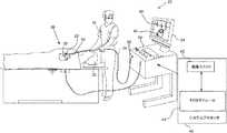
ここで図1を参照すると、この図は、本発明の一実施形態による、低侵襲性の医療システム20の概略図である。システム20は、典型的には身体器官への医療処置中に使用され、本明細書の記載では、身体器官は、例として、心臓を含むと想定され、このシステムは、心内心電図(ECG)信号をサンプリングし、典型的には記録及び解析するよう適用される。しかしながら、システム20は、他の身体器官からの信号をサンプリングするよう適用され得ることが理解されるであろう。Description of the System With reference to FIG. 1, this figure is a schematic diagram of a minimally invasive
以下の説明は、システム20が、プローブ24を用いて心臓22から心内ECG信号を感知すると想定する。プローブ24は典型的に、カテーテルを含み、本明細書においてはカテーテル24とも称される。プローブの遠位端26は、被験者30の体内に挿入される。プローブの遠位端26は、下記に詳しく述べられるように、ECG信号を感知する複数の電極28を含む。プローブを心臓22に挿入する前に、シース34の遠位端が望ましい位置になるまで、被験者にシースを挿入しておくことができる。シースの遠位端が正しく配置されたら、プローブ24の遠位端26がシースの遠位端から出るよう、プローブをシース34内に挿入することができる。本明細書の記載では、ユーザー32は典型的に医療専門家であり、このシース及びプローブを挿入すると想定される。 The following description assumes that the
システム20は、ECGモジュール44と通信する処理ユニット42を備えるシステムプロセッサ40によって制御され得る。プロセッサ40は、典型的にはマウス又はトラックボールなどの位置指示デバイスを含む、オペレーティングコントロールを備える、コンソール50上に据え付けられてもよい。コンソール50はまた、例えばカテーテル24の近位端52など、システム20の他の要素に接続され得る。医療専門家32は、位置指示デバイスを用いてプロセッサと対話し、このプロセッサは、以下に説明するように、システム20によって生じた結果を医療専門家に画面54上で提示するために使用され得る。 The
画面は、分析の結果及びECGモジュール44によるECG信号の処理を表示する。典型的には、得られたECG信号は、電位対時間グラフの形態で画面54上に提示され、このようなグラフの概略例60を図1に示す。しかしながら、得られたECG信号はまた、局所興奮時間(LAT)などの、ECG信号と関連付けられる他の結果を導出するために、プロセッサ40によって用いられてもよい。これらの結果は、典型的には、心臓22の内面の三次元(3D)マップ64の形態で画面54上に提示される。 The screen displays the results of the analysis and the processing of the ECG signal by the ECG module 44. Typically, the resulting ECG signal is presented on the
プロセッサ40は、プロセッサのメモリ内に記憶されたソフトウェアを用いてシステム20を操作する。ソフトウェアは、例えば、ネットワークを介して、電子的形態でプロセッサ40にダウンロードされてもよいし、又は代替的若しくは追加的に、磁気メモリ、光メモリ、若しくは電子メモリなどの、非一時的な有形媒体上に提供かつ/若しくは記憶されてもよい。 The
プロセッサ40は典型的に他のモジュールを含み、例えばプローブ追跡モジュール、及びアブレーションモジュール(調節された電力を、1つ又は2つ以上の電極28、又は遠位端の他の1つ又は2つ以上の電極に提供する)を含む。簡単にするために、このようなモジュールは図1には示していない。Biosense Webster(Diamond Bar,CA)により製造されるCarto(登録商標)システムは、このようなモジュールを使用する。 The
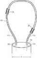
図2、3、4、5及び6は、本発明の実施形態による、プローブ24の遠位端26の異なる概略図である。図2は、シース34の遠位端から外に出る前の、又は再び収容された後の、プローブの遠位端を示す。図3は、シース34から外に出ている、又は再び収容されている時の、プローブの遠位端26を示す。図4及び5は、シース34から完全に外に出ている時のプローブの遠位端26を、2つの異なる方向で示している。図6は、遠位端26に取り付けられた単独ループの断面の模式図である。 2, 3, 4, 5 and 6 are different schematic views of the
遠位端26は複数の可撓性の弾性フィラメント100を含み、各フィラメント100は典型的に、ニチノールチューブなどの導電性要素で形成されている。図6に示すように、各フィラメントは2つの末端102、104を有し、この両方ともカテーテル24の遠位端26(典型的には遠位端の先端110)に固定されており、これにより各フィラメントがループを形成している。カテーテルの遠位端26は外径dを有する。フィラメント100が導電性の場合、例えばニチノールで形成されている場合には、通常これは絶縁材料で覆われている。あるいは、フィラメント100は、絶縁材料から形成され得る。 The
各フィラメント100は、そのフィラメントに固定された少なくとも1つの電極28を有する。フィラメントがチューブの形態である場合、導電性ワイヤ116は、フィラメント100が導電性の場合は絶縁されており、これがフィラメントの穴を通って電極に取り付けられていてよく、このワイヤはチューブの管腔内を通って供給されここを通り抜け(図6に図示)、カテーテル24の遠位端26及び近位端52を通ってコンソール50に至っていてよい。このようにして、電極により取得された信号は、プロセッサ49で解析することができる。あるいは、フィラメント100が管状でない場合は、ワイヤ116はフィラメントの外側に接着され得る。 Each
フィラメントは遠位端26に固定されており、これにより、各フィラメントが形成するループが相互に編み合わせられ、開放格子を形成する。開放格子のループは、編地状に配置されており、これにより互いに絡み合って交差し、かつ互いに対してスライドできるようになっている。構成要素フィラメントの弾性により、この開放格子は、図2に示すように、圧縮された開放格子118として、圧縮形態になり得る。フィラメントの開放格子はまた、非圧縮状態の開放格子120として、非圧縮形態にもなり得る。開放格子120の2つの図を、図4及び図5に示す。フィラメントが遠位端に固定されている場合、これらは、非圧縮状態の開放格子120が既定の形状を有するように配置され、この既定の形状は、仮想の外被内にフィットするような寸法にされる。開放格子120の場合、これは球形を有し、球形の仮想の外被124により囲まれ得る寸法にされる。 The filaments are secured to the
非圧縮状態の開放格子120は、相互に編み合わされたフィラメント100で形成されており、これらの間には開放空間130がある(図4及び5)。一実施形態において、この開放空間の合計面積と、フィラメント100の合計面積との比は、少なくとも20:1であり、これらの面積は両方とも、仮想外被の中心からの投影により、外被表面に生成される、開放空間及びフィラメントの面積として画定される。他の実施形態において、この比は少なくとも5:1であり得る。 The
非圧縮状態の開放格子120はまた、格子直径Dを有し、これは、格子を形成するフィラメント100の任意の2か所間の最大距離である。いくつかの実施形態において、格子直径Dはあるいは、非圧縮状態の開放格子を取り囲む寸法の仮想外被上の点間の最大距離と見なすことができ、よって、球形の仮想外被124の場合、格子直径Dは、外被124の直径に相当する。格子直径Dは、カテーテルの遠位端26の外径dの少なくとも5倍の大きさであり、典型的にはdの20倍以上の大きさである。 The uncompressed
上述のように、システム20を用いた典型的な心臓処置において、シース34が最初に挿入され、このシースの遠位端が心臓22に対して望ましい位置にされる。フィラメント100は圧縮されて、圧縮された開放格子118を形成し、これによりフィラメントがシース34に入ることができる。いくつかの実施形態において、圧縮された開放格子118は、遠位端26の外径と同じ直径dを有する円筒内に収まるほど十分に小さい。格子が圧縮形態である時、遠位端26とそれに取り付けられたフィラメントをシース内に押し込み、シースの奥まで達するようにすることができる。図2は、取り付けられたフィラメント100を備えた遠位端26がシース34内にある状態の模式図であり、図3は、フィラメントがシースから出た時の遠位端及びフィラメントの模式図である。 As mentioned above, in a typical cardiac procedure using the
フィラメント100は、シースから出ると圧縮から解放されて非圧縮状態になり、非圧縮状態の開放格子120を形成する。処置の終了時に、遠位端26を近位方向に引っ張ることができ、これによりフィラメント100がシースによって圧縮され、圧縮された開放格子118としてシース内に再び入る。 When the
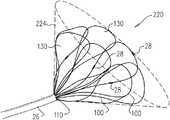
図7及び8は、本発明の別の一実施形態による、非圧縮時の開放格子220を示す2つの図である。以下に記載の違いは別として、非圧縮状態の開放格子220は非圧縮状態の開放格子120(図4及び5)と概ね同様であり、両方の格子において、及び両方の図群において同じ参照番号で示されている要素の構造及び操作は概ね同様である。よって、格子220は、複数の相互に編み合わされたフィラメント100で形成され、各フィラメントは少なくとも1つの電極28を有する。各フィラメントは、フィラメントのそれぞれの端が遠位先端110に固定され、これにより各フィラメントがループ形状になっている。編み合わされたフィラメント100の間には空間130がある。 7 and 8 are two diagrams showing the
しかしながら、非圧縮状態の開放格子120とは違って、非圧縮状態の開放格子220の既定の形状は、開いた手袋又は円錐形であり、格子220は円錐形の仮想外被224に取り囲まれた寸法になる。格子120と同様に、格子220は格子直径Dを有し、これは格子220を形成するフィラメント100の任意の2か所間の最大距離に等しい。あるいは、この格子直径は、外被224上の点間の最大距離と見なすことができる。格子120と同様に、非圧縮状態の開放格子220のフィラメント100は圧縮されて、圧縮された開放格子を形成し、これがシース34内に入ることができる。 However, unlike the uncompressed
本発明の実施形態は、非圧縮状態の開放格子120及び220を参照して上述された具体的な形状以外に、他の形状も含むことが理解されよう。例えば、遠位先端110に固定されたフィラメント100で形成され、この全体が圧縮されてシース24内にフィットし得る他の非圧縮状態の開放格子は、楕円体又は放物面形状である。すべてのそのような開放格子は、本発明の範囲内に含まれると想定される。 It will be appreciated that embodiments of the present invention include other shapes in addition to the specific shapes described above with reference to the uncompressed
したがって、上記に述べた実施形態は、例として引用したものであり、また本発明は、上記に詳細に示し説明したものに限定されないことが認識されよう。むしろ、本発明の範囲には、上記で説明した様々な特徴の組み合わせ及び部分的な組み合わせ、並びに、上記の説明を読むことで当業者には想到されるであろう、従来技術には開示されていないそれらの変形例及び改変例が含まれるものである。 Therefore, it will be appreciated that the embodiments described above are cited as examples, and that the present invention is not limited to those detailed and described above. Rather, the scope of the invention is disclosed in the prior art, which will be conceived by those skilled in the art by reading the combinations and partial combinations of the various features described above, as well as the description above. Those modifications and modifications that have not been made are included.
〔実施の態様〕
(1) 遠位端及び既定の外径を有するカテーテルと、
複数の弾性フィラメントと、を含む装置であって、各フィラメントが、それ自体に固定されている少なくとも1つの電極を有し、かつ、前記フィラメントをループとして保持するために前記カテーテルの遠位端内に固定される2つの端を有し、前記ループは、他の前記フィラメントの1つ又は2つ以上の他のループと相互に編み合わされ、これにより前記複数のフィラメントが開放格子を形成し、該開放格子が、非圧縮時に、前記カテーテルの前記外径の少なくとも5倍の大きさの格子直径になるまで拡張する、装置。
(2) 前記開放格子が圧縮されて、前記カテーテルの前記既定の外径に等しい直径を有する円筒内に収まる、実施態様1に記載の装置。
(3) 非圧縮時の前記開放格子が、仮想の球形の外被により囲まれるような寸法にされている、実施態様1に記載の装置。
(4) 非圧縮時の前記開放格子が、仮想の開放円錐形の外被(virtual open conical envelope)により囲まれるような寸法にされている、実施態様1に記載の装置。
(5) 非圧縮時の前記開放格子が、前記相互に編み合わされたフィラメント間に開放空間を有し、該開放空間により画定される第1合計面積と前記フィラメントにより画定される第2合計面積との比が少なくとも5:1である、実施態様1に記載の装置。[Implementation mode]
(1) With a catheter having a distal end and a predetermined outer diameter,
A device comprising a plurality of elastic filaments, each filament having at least one electrode fixed to itself and within the distal end of the catheter to hold the filament as a loop. The loops are braided together with one or more of the other loops of the other filaments so that the plurality of filaments form an open lattice. A device that expands an open grid, when uncompressed, to a grid diameter that is at least five times the outer diameter of the catheter.
(2) The device according to embodiment 1, wherein the open grid is compressed and fits within a cylinder having a diameter equal to the predetermined outer diameter of the catheter.
(3) The apparatus according to the first embodiment, wherein the open grid when not compressed is sized so as to be surrounded by a virtual spherical outer cover.
(4) The apparatus according to the first embodiment, wherein the open lattice when not compressed is sized so as to be surrounded by a virtual open conical envelope.
(5) The uncompressed open lattice has an open space between the filaments knitted with each other, and a first total area defined by the open space and a second total area defined by the filament. The apparatus according to embodiment 1, wherein the ratio of the above is at least 5: 1.
(6) 前記各弾性フィラメントが、管腔を有するチューブを含み、前記少なくとも1つの電極が、前記管腔を通り抜ける導電性ワイヤに取り付けられている、実施態様1に記載の装置。
(7) 前記格子の直径が、前記複数の弾性フィラメントの選択された部分間の最大距離を含む、実施態様1に記載の装置。
(8) 遠位端及び既定の外径を備えたカテーテルを提供することと、
複数の弾性フィラメントを、前記カテーテルの遠位端内に固定することと、を含む方法であって、各フィラメントが、それ自体に固定されている少なくとも1つの電極を有し、かつ、前記フィラメントをループとして保持するために前記カテーテルの遠位端内に固定される2つの端を有し、前記ループは、他の前記フィラメントの1つ又は2つ以上の他のループと相互に編み合わされ、これにより前記複数のフィラメントが、開放格子を形成し、該開放格子が、非圧縮時に、前記カテーテルの前記外径の少なくとも5倍の大きさの格子直径になるまで拡張する、方法。
(9) 前記開放格子が圧縮されて、前記カテーテルの前記既定の外径に等しい直径を有する円筒内に収まる、実施態様8に記載の方法。
(10) 非圧縮時の前記開放格子が、仮想の球形の外被により囲まれるような寸法にされる、実施態様8に記載の方法。(6) The apparatus according to embodiment 1, wherein each elastic filament comprises a tube having a lumen, and the at least one electrode is attached to a conductive wire passing through the lumen.
(7) The apparatus according to embodiment 1, wherein the diameter of the lattice includes a maximum distance between selected portions of the plurality of elastic filaments.
(8) To provide a catheter with a distal end and a predetermined outer diameter.
A method comprising fixing a plurality of elastic filaments within the distal end of the catheter, wherein each filament has at least one electrode fixed to itself and the filament is attached. It has two ends that are secured within the distal end of the catheter to hold as a loop, the loop being interwoven with one or more of the other loops of the other filaments. A method in which the plurality of filaments form an open grid, which, when uncompressed, expands to a grid diameter at least five times the outer diameter of the catheter.
(9) The method of embodiment 8, wherein the open grid is compressed and fits within a cylinder having a diameter equal to the predetermined outer diameter of the catheter.
(10) The method according to embodiment 8, wherein the open grid when uncompressed is sized so as to be surrounded by a virtual spherical outer cover.
(11) 非圧縮時の前記開放格子が、仮想の開放円錐形の外被により囲まれるような寸法にされる、実施態様8に記載の方法。
(12) 非圧縮時の前記開放格子が、前記相互に編み合わされたフィラメント間に開放空間を有し、該開放空間により画定される第1合計面積と前記フィラメントにより画定される第2合計面積との比が少なくとも5:1である、実施態様8に記載の方法。
(13) 前記各弾性フィラメントが、管腔を有するチューブを含み、前記少なくとも1つの電極が、前記管腔を通り抜ける導電性ワイヤに取り付けられている、実施態様8に記載の方法。
(14) 前記格子の直径が、前記複数の弾性フィラメントの選択された部分間の最大距離を含む、実施態様8に記載の方法。(11) The method according to embodiment 8, wherein the open grid when uncompressed is sized so as to be surrounded by a virtual open conical outer cover.
(12) The uncompressed open lattice has an open space between the filaments knitted with each other, and a first total area defined by the open space and a second total area defined by the filament. 8. The method of embodiment 8, wherein the ratio is at least 5: 1.
(13) The method of embodiment 8, wherein each elastic filament comprises a tube having a lumen and the at least one electrode is attached to a conductive wire passing through the lumen.
(14) The method of embodiment 8, wherein the diameter of the lattice includes a maximum distance between selected portions of the plurality of elastic filaments.
Claims (8)
Translated fromJapanese複数の弾性フィラメントと、を含む装置であって、各弾性フィラメントが、それ自体に固定されている少なくとも1つの電極を有し、かつ、前記弾性フィラメントをループとして保持するために前記カテーテルの前記遠位端内に固定される2つの端を有し、前記ループは、他の前記弾性フィラメントの1つ又は2つ以上の他のループと相互に編み合わされかつ他の前記弾性フィラメントの前記1つ又は2つ以上の他のループに対してスライドでき、これにより複数の前記弾性フィラメントが開放格子を形成し、該開放格子が、前記カテーテルの前記既定の外径に等しい直径を有する円筒から出て非圧縮形態になり、非圧縮時に、前記カテーテルの前記既定の外径の少なくとも20倍の大きさの格子直径になるまで拡張し、
非圧縮時の前記開放格子が、相互に編み合わされた前記弾性フィラメント間に開放空間を有し、該開放空間により画定される第1合計面積と前記弾性フィラメントにより画定される第2合計面積との比が少なくとも20:1である、装置。With a catheter with a distal end and a defined outer diameter,
A device comprising a plurality of elastic filaments, wherein each elastic filament has at least one electrode fixed to itself, and the distance of the catheter to hold the elastic filament as a loop. Having two ends fixed within the position end, the loop is interwoven with one or more of the other elastic filaments and the one or more of the other elastic filaments. It can slide against two or more other loops, whereby the elastic filaments form an open lattice, which does not emerge from a cylinder having a diameter equal to the predetermined outer diameter of the catheter. It is in a compressed form and, when uncompressed, expands to a lattice diameter that is at least 20 times larger than the predetermined outer diameter of the catheter.
The uncompressed open lattice has an open space between the elastic filaments woven together, and the first total area defined by the open space and the second total area defined by the elastic filaments. A device having a ratio of at least 20: 1.
非圧縮時の前記開放格子は、相互に編み合わされた前記弾性フィラメント間に開放空間を有し、該開放空間により画定される第1合計面積と前記弾性フィラメントにより画定される第2合計面積との比が少なくとも20:1である、方法。A method comprising fixing a plurality of elastic filaments within the distal end of a catheter having a predetermined outer diameter, wherein each elastic filament has at least one electrode fixed to itself. And having two ends fixed within the distal end of the catheter to hold the elastic filament as a loop, the loop being one or more of the other elastic filaments. It is interwoven with the other loops and can slide relative to the one or more other loops of the other elastic filament so that the plurality of elastic filaments form an open lattice and the open lattice. Out of a cylinder having a diameter equal to the predetermined outer diameter of the catheter into an uncompressed form, until the lattice diameter is at least 20 times larger than the predetermined outer diameter of the catheter when uncompressed. Expand and
The open lattice when uncompressed has an open space between the elastic filaments woven together, and has a first total area defined by the open space and a second total area defined by the elastic filament. A method in which the ratio is at least 20: 1.
Applications Claiming Priority (3)
| Application Number | Priority Date | Filing Date | Title |
|---|---|---|---|
| US14/715,958 | 2015-05-19 | ||
| US14/715,958US20160338770A1 (en) | 2015-05-19 | 2015-05-19 | Woven foldable catheter |
| JP2016099474AJP2016214865A (en) | 2015-05-19 | 2016-05-18 | Knitted foldable catheter |
Related Parent Applications (1)
| Application Number | Title | Priority Date | Filing Date |
|---|---|---|---|
| JP2016099474ADivisionJP2016214865A (en) | 2015-05-19 | 2016-05-18 | Knitted foldable catheter |
Publications (1)
| Publication Number | Publication Date |
|---|---|
| JP2021106984Atrue JP2021106984A (en) | 2021-07-29 |
Family
ID=56014909
Family Applications (2)
| Application Number | Title | Priority Date | Filing Date |
|---|---|---|---|
| JP2016099474APendingJP2016214865A (en) | 2015-05-19 | 2016-05-18 | Knitted foldable catheter |
| JP2021075916APendingJP2021106984A (en) | 2015-05-19 | 2021-04-28 | Woven foldable catheter |
Family Applications Before (1)
| Application Number | Title | Priority Date | Filing Date |
|---|---|---|---|
| JP2016099474APendingJP2016214865A (en) | 2015-05-19 | 2016-05-18 | Knitted foldable catheter |
Country Status (8)
| Country | Link |
|---|---|
| US (1) | US20160338770A1 (en) |
| EP (2) | EP3095405B1 (en) |
| JP (2) | JP2016214865A (en) |
| CN (1) | CN106166319A (en) |
| AU (1) | AU2016202564A1 (en) |
| CA (1) | CA2928230A1 (en) |
| ES (1) | ES2758097T3 (en) |
| IL (1) | IL245248B (en) |
Families Citing this family (45)
| Publication number | Priority date | Publication date | Assignee | Title |
|---|---|---|---|---|
| WO2015192018A1 (en) | 2014-06-12 | 2015-12-17 | Iowa Approach Inc. | Method and apparatus for rapid and selective tissue ablation with cooling |
| EP3154463B1 (en) | 2014-06-12 | 2019-03-27 | Farapulse, Inc. | Apparatus for rapid and selective transurethral tissue ablation |
| EP3206613B1 (en) | 2014-10-14 | 2019-07-03 | Farapulse, Inc. | Apparatus for rapid and safe pulmonary vein cardiac ablation |
| US10130423B1 (en) | 2017-07-06 | 2018-11-20 | Farapulse, Inc. | Systems, devices, and methods for focal ablation |
| US20170189097A1 (en) | 2016-01-05 | 2017-07-06 | Iowa Approach Inc. | Systems, apparatuses and methods for delivery of ablative energy to tissue |
| US10660702B2 (en) | 2016-01-05 | 2020-05-26 | Farapulse, Inc. | Systems, devices, and methods for focal ablation |
| US10172673B2 (en) | 2016-01-05 | 2019-01-08 | Farapulse, Inc. | Systems devices, and methods for delivery of pulsed electric field ablative energy to endocardial tissue |
| US12144541B2 (en) | 2016-01-05 | 2024-11-19 | Boston Scientific Scimed, Inc. | Systems, apparatuses and methods for delivery of ablative energy to tissue |
| US10905329B2 (en) | 2016-06-09 | 2021-02-02 | Biosense Webster (Israel) Ltd. | Multi-function conducting elements for a catheter |
| US11344259B2 (en)* | 2017-01-11 | 2022-05-31 | Abbott Cardiovascular Systems Inc. | Expandable member for an electrophysiology catheter |
| US9987081B1 (en) | 2017-04-27 | 2018-06-05 | Iowa Approach, Inc. | Systems, devices, and methods for signal generation |
| US12029545B2 (en) | 2017-05-30 | 2024-07-09 | Biosense Webster (Israel) Ltd. | Catheter splines as location sensors |
| JP7586706B2 (en) | 2017-09-12 | 2024-11-19 | ボストン サイエンティフィック サイムド,インコーポレイテッド | Systems, devices and methods for focal ventricular ablation - Patents.com |
| EP3749191A1 (en)* | 2018-02-06 | 2020-12-16 | Biosense Webster (Israel) Ltd | Medical probe with staggered microelectrode configuration |
| US20190314083A1 (en) | 2018-04-11 | 2019-10-17 | Biosense Webster (Israel) Ltd. | Flexible Multi-Arm Catheter with Diametrically Opposed Sensing Electrodes |
| WO2019217433A1 (en) | 2018-05-07 | 2019-11-14 | Farapulse, Inc. | Systems, apparatuses and methods for delivery of ablative energy to tissue |
| US11642165B2 (en)* | 2018-06-29 | 2023-05-09 | Biosense Webster (Israel) Ltd. | Catheter with mechanically expandable element having flex circuit |
| US10687892B2 (en) | 2018-09-20 | 2020-06-23 | Farapulse, Inc. | Systems, apparatuses, and methods for delivery of pulsed electric field ablative energy to endocardial tissue |
| US11045628B2 (en) | 2018-12-11 | 2021-06-29 | Biosense Webster (Israel) Ltd. | Balloon catheter with high articulation |
| US11547473B2 (en)* | 2018-12-11 | 2023-01-10 | Neurent Medical Limited | Systems and methods for therapeutic nasal neuromodulation |
| US11207016B2 (en) | 2018-12-28 | 2021-12-28 | Biosense Webster (Israel) Ltd. | Mapping ECG signals using a multipole electrode assembly |
| US11850051B2 (en) | 2019-04-30 | 2023-12-26 | Biosense Webster (Israel) Ltd. | Mapping grid with high density electrode array |
| US11540878B2 (en)* | 2019-07-17 | 2023-01-03 | Biosense Webster (Israel) Ltd. | Blooming leaflet catheter with high density electrode array |
| US11712172B2 (en) | 2019-07-18 | 2023-08-01 | Biosense Webster (Israel) Ltd. | Visual guidance for positioning a distal end of a medical probe |
| US11950930B2 (en) | 2019-12-12 | 2024-04-09 | Biosense Webster (Israel) Ltd. | Multi-dimensional acquisition of bipolar signals from a catheter |
| US11517218B2 (en) | 2019-12-20 | 2022-12-06 | Biosense Webster (Israel) Ltd. | Selective graphical presentation of electrophysiological parameters |
| US12232874B2 (en) | 2020-05-29 | 2025-02-25 | Biosense Webster (Israel) Ltd. | Electrode apparatus for diagnosis of arrhythmias |
| US11987017B2 (en) | 2020-06-08 | 2024-05-21 | Biosense Webster (Israel) Ltd. | Features to assist in assembly and testing of devices |
| US12310652B2 (en) | 2020-07-24 | 2025-05-27 | Boston Scientific Scimed, Inc. | Hybrid electroporation ablation catheter |
| WO2022020478A1 (en) | 2020-07-24 | 2022-01-27 | Boston Scientific Scimed Inc | Electric field application for single shot cardiac ablation by irreversible electroporation |
| US12048479B2 (en) | 2020-09-10 | 2024-07-30 | Biosense Webster (Israel) Ltd. | Surface mounted electrode catheter |
| US11950841B2 (en) | 2020-09-22 | 2024-04-09 | Biosense Webster (Israel) Ltd. | Basket catheter having insulated ablation electrodes and diagnostic electrodes |
| US11950840B2 (en) | 2020-09-22 | 2024-04-09 | Biosense Webster (Israel) Ltd. | Basket catheter having insulated ablation electrodes |
| US12082875B2 (en) | 2020-09-24 | 2024-09-10 | Biosense Webster (Israel) Ltd | Balloon catheter having a coil for sensing tissue temperature and position of the balloon |
| US11974803B2 (en) | 2020-10-12 | 2024-05-07 | Biosense Webster (Israel) Ltd. | Basket catheter with balloon |
| US12201786B2 (en) | 2020-12-17 | 2025-01-21 | Biosense Webster (Israel) Ltd. | Measurement of distal end dimension of catheters using magnetic fields |
| US11918383B2 (en) | 2020-12-21 | 2024-03-05 | Biosense Webster (Israel) Ltd. | Visualizing performance of catheter electrodes |
| JP2024504184A (en) | 2021-01-27 | 2024-01-30 | ボストン サイエンティフィック サイムド,インコーポレイテッド | Voltage-controlled pulse sequence for irreversible electroporation ablation |
| AU2022234310A1 (en)* | 2021-03-10 | 2023-09-28 | Cardiofocus, Inc. | Devices for the delivery of pulsed electric fields in the treatment of cardiac tissue |
| US12064170B2 (en) | 2021-05-13 | 2024-08-20 | Biosense Webster (Israel) Ltd. | Distal assembly for catheter with lumens running along spines |
| US12364426B2 (en) | 2021-08-12 | 2025-07-22 | Biosense Webster (Israel) Ltd. | Electro-anatomical mapping and annotation presented in electrophysiological procedures |
| US12004804B2 (en) | 2021-09-09 | 2024-06-11 | Biosense Webster (Israel) Ltd. | Basket catheter with mushroom shape distal tip |
| US12011280B2 (en) | 2021-10-04 | 2024-06-18 | Biosense Webster (Israel) Ltd. | Electrophysiological mapping in the presence of injury current |
| US12419683B2 (en) | 2021-12-22 | 2025-09-23 | Biosense Webster (Israel) Ltd. | Irreversible electroporation with shorted electrodes |
| US20240197391A1 (en)* | 2022-12-15 | 2024-06-20 | Biosense Webster (Israel) Ltd. | Basket assembly with atraumatic tip electrode and methods of making thereof |
Citations (5)
| Publication number | Priority date | Publication date | Assignee | Title |
|---|---|---|---|---|
| JP2002126096A (en)* | 2000-10-27 | 2002-05-08 | Aisin Seiki Co Ltd | Catheter equipped with electrode |
| US20050222563A1 (en)* | 2004-03-31 | 2005-10-06 | Mcdaniel Benjamin D | Catheter for circumferential ablation at or near a pulmonary vein |
| WO2014022221A1 (en)* | 2012-08-02 | 2014-02-06 | Ethicon Endo-Surgery, Inc. | Flexible expandable electrode and method of intraluminal delivery of pulsed power |
| JP2014512226A (en)* | 2011-04-22 | 2014-05-22 | トペラ インコーポレイテッド | Basket style cardiac mapping catheter with flexible electrode assembly for detecting cardiac rhythm disorders |
| WO2015187430A2 (en)* | 2014-06-04 | 2015-12-10 | Boston Scientific Scimed, Inc. | Electrode assembly |
Family Cites Families (7)
| Publication number | Priority date | Publication date | Assignee | Title |
|---|---|---|---|---|
| US6514249B1 (en)* | 1997-07-08 | 2003-02-04 | Atrionix, Inc. | Positioning system and method for orienting an ablation element within a pulmonary vein ostium |
| US6428537B1 (en)* | 1998-05-22 | 2002-08-06 | Scimed Life Systems, Inc. | Electrophysiological treatment methods and apparatus employing high voltage pulse to render tissue temporarily unresponsive |
| US20060089637A1 (en)* | 2004-10-14 | 2006-04-27 | Werneth Randell L | Ablation catheter |
| US8224416B2 (en)* | 2007-05-09 | 2012-07-17 | St. Jude Medical, Atrial Fibrillation Division, Inc. | Basket catheter having multiple electrodes |
| US9480525B2 (en)* | 2011-01-21 | 2016-11-01 | Kardium, Inc. | High-density electrode-based medical device system |
| EP2890292B1 (en)* | 2012-08-31 | 2021-01-13 | Acutus Medical, Inc. | Catheter system for the heart |
| CN106687168A (en)* | 2014-09-12 | 2017-05-17 | X-节奏有限责任公司 | Multi-electrode mapping catheter |
- 2015
- 2015-05-19USUS14/715,958patent/US20160338770A1/ennot_activeAbandoned
- 2016
- 2016-04-20ILIL245248Apatent/IL245248B/enactiveIP Right Grant
- 2016-04-22AUAU2016202564Apatent/AU2016202564A1/ennot_activeWithdrawn
- 2016-04-26CACA2928230Apatent/CA2928230A1/ennot_activeAbandoned
- 2016-05-18JPJP2016099474Apatent/JP2016214865A/enactivePending
- 2016-05-18CNCN201610330330.6Apatent/CN106166319A/enactivePending
- 2016-05-18EPEP16170154.5Apatent/EP3095405B1/ennot_activeNot-in-force
- 2016-05-18ESES18167661Tpatent/ES2758097T3/enactiveActive
- 2016-05-18EPEP18167661.0Apatent/EP3366251B1/enactiveActive
- 2021
- 2021-04-28JPJP2021075916Apatent/JP2021106984A/enactivePending
Patent Citations (5)
| Publication number | Priority date | Publication date | Assignee | Title |
|---|---|---|---|---|
| JP2002126096A (en)* | 2000-10-27 | 2002-05-08 | Aisin Seiki Co Ltd | Catheter equipped with electrode |
| US20050222563A1 (en)* | 2004-03-31 | 2005-10-06 | Mcdaniel Benjamin D | Catheter for circumferential ablation at or near a pulmonary vein |
| JP2014512226A (en)* | 2011-04-22 | 2014-05-22 | トペラ インコーポレイテッド | Basket style cardiac mapping catheter with flexible electrode assembly for detecting cardiac rhythm disorders |
| WO2014022221A1 (en)* | 2012-08-02 | 2014-02-06 | Ethicon Endo-Surgery, Inc. | Flexible expandable electrode and method of intraluminal delivery of pulsed power |
| WO2015187430A2 (en)* | 2014-06-04 | 2015-12-10 | Boston Scientific Scimed, Inc. | Electrode assembly |
Also Published As
| Publication number | Publication date |
|---|---|
| US20160338770A1 (en) | 2016-11-24 |
| EP3095405A1 (en) | 2016-11-23 |
| EP3366251B1 (en) | 2019-09-04 |
| CN106166319A (en) | 2016-11-30 |
| EP3366251A1 (en) | 2018-08-29 |
| EP3095405B1 (en) | 2018-04-18 |
| AU2016202564A1 (en) | 2016-12-08 |
| ES2758097T3 (en) | 2020-05-04 |
| JP2016214865A (en) | 2016-12-22 |
| CA2928230A1 (en) | 2016-11-19 |
| IL245248B (en) | 2019-12-31 |
| IL245248A0 (en) | 2016-08-31 |
Similar Documents
| Publication | Publication Date | Title |
|---|---|---|
| JP2021106984A (en) | Woven foldable catheter | |
| CN104644162B (en) | Flexible multi-arm diagnostic catheter | |
| CN106859638B (en) | Having interconnections of frames electrode array catheter | |
| CN107440790B (en) | Basket catheter with pre-strained frame | |
| US10362991B2 (en) | Convertible basket catheter | |
| CN105796090B (en) | Basket catheter with improved ridge flexibility | |
| US20080058794A1 (en) | Electrophysiology System for Mapping and Ablating Arrhythmias | |
| US10974031B2 (en) | Balloon catheter with internal distal end | |
| CA2980803A1 (en) | Basket catheter conforming to organ using strain-relief elements | |
| JP2017205518A (en) | Multi-electrode catheter spine and method of making the same | |
| US20100198041A1 (en) | Apparatus and method for positioning and retention of catheter | |
| JP2017522923A (en) | Electrode assembly with atraumatic distal tip | |
| JP2015167864A (en) | Multi-arm catheter with signal transmission via braided wire | |
| JP2011528581A (en) | Method and system for locating energy sources | |
| EP3973903B1 (en) | Basket catheter having insulated ablation electrodes and diagnostic electrodes | |
| JP2023530886A (en) | Chronically Implantable Systems and Methods for Affecting Cardiac Contraction and/or Relaxation | |
| JP2017113539A (en) | Dual node multiray electrode catheter | |
| US12342998B2 (en) | Sensor enabled left atrial appendage occlusion system for three-dimensional imaging and method thereof | |
| EP3977954B1 (en) | Basket catheter having insulated ablation electrodes | |
| WO2023150489A2 (en) | Methods and systems for neuromodulation | |
| JP2018079317A (en) | Multi-electrode catheter for preventing flow restriction of physiological fluid | |
| US20190046062A1 (en) | Coronary sinus electrophysiology measurements device and methods | |
| JP2021533915A (en) | Snare integrated myocardial electrical signal detection catheter |
Legal Events
| Date | Code | Title | Description |
|---|---|---|---|
| A621 | Written request for application examination | Free format text:JAPANESE INTERMEDIATE CODE: A621 Effective date:20210428 | |
| A977 | Report on retrieval | Free format text:JAPANESE INTERMEDIATE CODE: A971007 Effective date:20220225 | |
| A131 | Notification of reasons for refusal | Free format text:JAPANESE INTERMEDIATE CODE: A131 Effective date:20220301 | |
| A02 | Decision of refusal | Free format text:JAPANESE INTERMEDIATE CODE: A02 Effective date:20221004 |