JP2021106558A - Work vehicle and travel management system therefor - Google Patents
Work vehicle and travel management system thereforDownload PDFInfo
- Publication number
- JP2021106558A JP2021106558AJP2019239899AJP2019239899AJP2021106558AJP 2021106558 AJP2021106558 AJP 2021106558AJP 2019239899 AJP2019239899 AJP 2019239899AJP 2019239899 AJP2019239899 AJP 2019239899AJP 2021106558 AJP2021106558 AJP 2021106558A
- Authority
- JP
- Japan
- Prior art keywords
- work
- state
- vehicle body
- marker
- traveling
- Prior art date
- Legal status (The legal status is an assumption and is not a legal conclusion. Google has not performed a legal analysis and makes no representation as to the accuracy of the status listed.)
- Granted
Links
Images


Classifications
- G—PHYSICS
- G06—COMPUTING OR CALCULATING; COUNTING
- G06T—IMAGE DATA PROCESSING OR GENERATION, IN GENERAL
- G06T7/00—Image analysis
- G06T7/70—Determining position or orientation of objects or cameras
- G06T7/73—Determining position or orientation of objects or cameras using feature-based methods
- A—HUMAN NECESSITIES
- A01—AGRICULTURE; FORESTRY; ANIMAL HUSBANDRY; HUNTING; TRAPPING; FISHING
- A01B—SOIL WORKING IN AGRICULTURE OR FORESTRY; PARTS, DETAILS, OR ACCESSORIES OF AGRICULTURAL MACHINES OR IMPLEMENTS, IN GENERAL
- A01B59/00—Devices specially adapted for connection between animals or tractors and agricultural machines or implements
- A01B59/04—Devices specially adapted for connection between animals or tractors and agricultural machines or implements for machines pulled or pushed by a tractor
- A01B59/042—Devices specially adapted for connection between animals or tractors and agricultural machines or implements for machines pulled or pushed by a tractor having pulling means arranged on the rear part of the tractor
- B—PERFORMING OPERATIONS; TRANSPORTING
- B60—VEHICLES IN GENERAL
- B60W—CONJOINT CONTROL OF VEHICLE SUB-UNITS OF DIFFERENT TYPE OR DIFFERENT FUNCTION; CONTROL SYSTEMS SPECIALLY ADAPTED FOR HYBRID VEHICLES; ROAD VEHICLE DRIVE CONTROL SYSTEMS FOR PURPOSES NOT RELATED TO THE CONTROL OF A PARTICULAR SUB-UNIT
- B60W50/00—Details of control systems for road vehicle drive control not related to the control of a particular sub-unit, e.g. process diagnostic or vehicle driver interfaces
- A—HUMAN NECESSITIES
- A01—AGRICULTURE; FORESTRY; ANIMAL HUSBANDRY; HUNTING; TRAPPING; FISHING
- A01B—SOIL WORKING IN AGRICULTURE OR FORESTRY; PARTS, DETAILS, OR ACCESSORIES OF AGRICULTURAL MACHINES OR IMPLEMENTS, IN GENERAL
- A01B69/00—Steering of agricultural machines or implements; Guiding agricultural machines or implements on a desired track
- A01B69/003—Steering or guiding of machines or implements pushed or pulled by or mounted on agricultural vehicles such as tractors, e.g. by lateral shifting of the towing connection
- A—HUMAN NECESSITIES
- A01—AGRICULTURE; FORESTRY; ANIMAL HUSBANDRY; HUNTING; TRAPPING; FISHING
- A01B—SOIL WORKING IN AGRICULTURE OR FORESTRY; PARTS, DETAILS, OR ACCESSORIES OF AGRICULTURAL MACHINES OR IMPLEMENTS, IN GENERAL
- A01B76/00—Parts, details or accessories of agricultural machines or implements, not provided for in groups A01B51/00 - A01B75/00
- B—PERFORMING OPERATIONS; TRANSPORTING
- B60—VEHICLES IN GENERAL
- B60W—CONJOINT CONTROL OF VEHICLE SUB-UNITS OF DIFFERENT TYPE OR DIFFERENT FUNCTION; CONTROL SYSTEMS SPECIALLY ADAPTED FOR HYBRID VEHICLES; ROAD VEHICLE DRIVE CONTROL SYSTEMS FOR PURPOSES NOT RELATED TO THE CONTROL OF A PARTICULAR SUB-UNIT
- B60W40/00—Estimation or calculation of non-directly measurable driving parameters for road vehicle drive control systems not related to the control of a particular sub unit, e.g. by using mathematical models
- A—HUMAN NECESSITIES
- A01—AGRICULTURE; FORESTRY; ANIMAL HUSBANDRY; HUNTING; TRAPPING; FISHING
- A01B—SOIL WORKING IN AGRICULTURE OR FORESTRY; PARTS, DETAILS, OR ACCESSORIES OF AGRICULTURAL MACHINES OR IMPLEMENTS, IN GENERAL
- A01B69/00—Steering of agricultural machines or implements; Guiding agricultural machines or implements on a desired track
- A01B69/001—Steering by means of optical assistance, e.g. television cameras
- G—PHYSICS
- G06—COMPUTING OR CALCULATING; COUNTING
- G06T—IMAGE DATA PROCESSING OR GENERATION, IN GENERAL
- G06T2207/00—Indexing scheme for image analysis or image enhancement
- G06T2207/30—Subject of image; Context of image processing
- G06T2207/30204—Marker
- G—PHYSICS
- G06—COMPUTING OR CALCULATING; COUNTING
- G06T—IMAGE DATA PROCESSING OR GENERATION, IN GENERAL
- G06T2207/00—Indexing scheme for image analysis or image enhancement
- G06T2207/30—Subject of image; Context of image processing
- G06T2207/30248—Vehicle exterior or interior
- G06T2207/30252—Vehicle exterior; Vicinity of vehicle
Landscapes
- Engineering & Computer Science (AREA)
- Life Sciences & Earth Sciences (AREA)
- Mechanical Engineering (AREA)
- Soil Sciences (AREA)
- Environmental Sciences (AREA)
- Physics & Mathematics (AREA)
- Transportation (AREA)
- Automation & Control Theory (AREA)
- Computer Vision & Pattern Recognition (AREA)
- General Physics & Mathematics (AREA)
- Theoretical Computer Science (AREA)
- Mathematical Physics (AREA)
- Human Computer Interaction (AREA)
- Zoology (AREA)
- Guiding Agricultural Machines (AREA)
- Agricultural Machines (AREA)
Abstract
Description
Translated fromJapanese本発明は、例えば、トラクタ等の作業車両及び作業車両の走行管理システムに関する。 The present invention relates to, for example, a work vehicle such as a tractor and a travel management system for the work vehicle.
従来、トラクタ等の作業車両に連結した作業装置に無線タグを装着した技術として特許文献1に示す技術が知られている。特許文献1では、作業を行う作業部と、作業部を支持し且つ車体に連結可能なフレームと、少なくとも識別情報を記憶する記憶部と、識別情報を送信する通信部とを有し且つ作業部又はフレームに取付けられた無線タグとを備えている。 Conventionally, the technique shown in
また、トラクタの作業車両にカメラを搭載した技術として特許文献2に示す技術が知られている。特許文献2では、車体の周辺を撮影する複数のカメラと、作業走行状況を検出する作業走行状況検出センサ群と、作業走行状況検出センサ群からの検出信号に基づいて注目領域を決定する注目領域決定部と、複数のカメラのうち注目領域が撮影視野に入っているカメラの撮影画像を優先表示画像とする優先表示画像決定部と、複数のカメラの撮影画像を視点変換して合成することで車体周辺の俯瞰画像を生成する俯瞰画像生成部と、俯瞰画像を表示する第1表示領域と優先表示画像を表示する第2表示領域とに区分けされたモニタ表示画面を生成するモニタ画面生成部と、モニタ表示画面を表示するモニタとを備えている。 Further, a technique shown in
特許文献1では、トラクタの後部に装着した作業装置が何であるかを無線タグから送信された情報によって把握することができる。また、特許文献2では、複数のカメラによってトラクタの周囲の状況を把握することができる。特許文献1及び2のいずれにおいても、作業装置の種類等が把握することができるものの、作業装置の詳細な状態を把握することができないのが実情である。 In
そこで、本発明は上記問題点に鑑み、簡単に作業装置の状態を把握することができる作業車両及び作業車両の走行管理システムを提供することを目的とする。 Therefore, in view of the above problems, an object of the present invention is to provide a work vehicle and a travel management system for the work vehicle, which can easily grasp the state of the work device.
この技術的課題を解決するための本発明の技術的手段は、以下に示す点を特徴とする。
作業車両は、作業装置を連結する連結部を有する走行車体と、前記作業装置に設けられたマーカ部材と、前記走行車体に設けられ且つ、前記マーカ部材を検出するマーカ検出装置と、前記マーカ検出装置が検出した検出データに基づいて、前記作業装置の状態を演算する状態演算装置と、を備えている。The technical means of the present invention for solving this technical problem is characterized by the following points.
The work vehicle includes a traveling vehicle body having a connecting portion for connecting the working devices, a marker member provided on the working device, a marker detecting device provided on the traveling vehicle body and detecting the marker member, and the marker detection device. It includes a state calculation device that calculates the state of the work device based on the detection data detected by the device.
前記状態演算装置は、前記作業装置の状態として前記作業装置の位置を演算する。
前記状態演算装置は、前記作業装置の状態として前記作業装置の姿勢を演算する。
前記状態演算装置は、前記作業装置の状態として前記走行車体と作業装置との相対位置を演算する。
前記走行車体は、当該走行車体の位置である車体位置を測位する測位装置を備え、前記状態演算装置は、前記測位位置で演算された車体位置と、前記作業装置の状態とに基づいて、前記作業装置の位置である装置位置を演算する。The state calculation device calculates the position of the work device as the state of the work device.
The state calculation device calculates the posture of the work device as the state of the work device.
The state calculation device calculates the relative position between the traveling vehicle body and the work device as the state of the work device.
The traveling vehicle body includes a positioning device for positioning the vehicle body position, which is the position of the traveling vehicle body, and the state calculation device is based on the vehicle body position calculated at the positioning position and the state of the working device. Calculate the device position, which is the position of the work device.
前記マーカ検出装置は、前記マーカ部材を撮像する撮像装置である。
作業車両の走行管理システムは、走行車体に連結された作業装置に設けられたマーカ部材と、前記走行車体に設けられ且つ、前記マーカ部材を検出するマーカ検出装置と、前記マーカ検出装置が検出した検出データに基づいて、前記作業装置の状態を演算する状態演算装置と、を備えている。The marker detection device is an imaging device that images the marker member.
The travel management system of the work vehicle is detected by a marker member provided in the work device connected to the traveling vehicle body, a marker detection device provided in the traveling vehicle body and detecting the marker member, and the marker detection device. It includes a state calculation device that calculates the state of the work device based on the detection data.
作業車両の走行管理システムは、前記走行車体の位置である車体位置を測位する測位装置を備え、前記状態演算装置は、前記測位位置で演算された車体位置と、前記作業装置の状態とに基づいて、前記作業装置の位置である装置位置を演算する。 The travel management system of the work vehicle includes a positioning device for positioning the vehicle body position, which is the position of the traveling vehicle body, and the state calculation device is based on the vehicle body position calculated at the positioning position and the state of the work device. The device position, which is the position of the work device, is calculated.
本発明によれば、簡単に作業装置の状態を把握することができる。 According to the present invention, the state of the working apparatus can be easily grasped.
以下、本発明の実施の形態を図面に基づいて説明する。
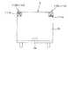
図1は、作業車両1に作業装置2を連結した状態を示している。
まず、作業車両の1つであるトラクタをについて説明する。
トラクタ1は、走行装置7を有する走行車体3と、原動機4と、変速装置5とを備えている。走行装置7は、前輪7F及び後輪7Rを有する装置である。前輪7Fは、タイヤ型であってもクローラ型であってもよい。また、後輪7Rも、タイヤ型であってもクローラ型であってもよい。原動機4は、ディーゼルエンジン、電動モータ等である。変速装置5は、変速によって走行装置7の推進力を切換可能であると共に、走行装置7の前進、後進の切換が可能である。走行車体3にはキャビン9が設けられ、当該キャビン9内には運転席10が設けられている。Hereinafter, embodiments of the present invention will be described with reference to the drawings.
FIG. 1 shows a state in which the
First, a tractor, which is one of the work vehicles, will be described.
The
また、走行車体3の後部には、作業装置2を連結する連結部8が設けられている。連結部は、作業装置2と走行車体3とを連結し且つ昇降を行わないスイングドローバ、3点リンク機構等で構成されて昇降を行う昇降装置等である。連結部8には、作業装置2が着脱可能である。作業装置2を連結部8に連結することによって、走行車体3によって作業装置2を牽引することができる。作業装置2は、運搬するトレーラ、耕耘する耕耘装置、肥料を散布する肥料散布装置、苗を植え付ける移植装置、灌水を行う灌水装置、農薬を散布する農薬散布装置、種を散布する播種散布装置、牧草等の刈取を行う刈取装置、牧草等の拡散を行う拡散装置、牧草等の集草を行う集草装置、牧草等の成形を行う成形装置、複数の作業を行う複合装置等である。この実施形態では、作業装置2はトレーラであるとして説明を進める。 Further, a connecting
作業装置2は、連結バー2aを有していて、当該連結バー2aは、作業装置2のフレームにボルト等の締結具により固定されていて、幅方向に揺動不能となっている。なお、連結バー2aは、作業装置2のフレームに溶接により固着されていてもよい。連結バー2aの前端には、挿入孔2cが形成されている。
図2に示すように、連結部8は、例えば、牽引ヒッチであって、走行車体3から後方に延設された延設体8aと、延設体8aの後端に設けられた枢支ピン8bとを含んでいる。延設体8aの前部は、変速装置5のミッションケール、デフケース等にボルト等の締結具より固定されていて、幅方向に揺動不能となっている。延設体8aの後部は、上壁8a1と、上壁8a1から離間した下壁8a2とが形成されていて、上壁8a1と下壁8a2とに枢支ピン8bが貫通している。作業装置2の連結バー2aを上壁8a1と下壁8a2との間に位置させ、枢支ピン8bを連結バー2aの挿入孔に挿入することによって、作業装置2を連結部8に連結することができる。The
As shown in FIG. 2, the connecting
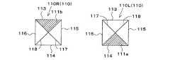
図3に示すように、作業装置2には、複数のマーカ部材110が設けられている。図3は、走行車体3の後部側から後方に連結された作業装置2を見た状態を示している。複数のマーカ部材110は、第1マーカ部材110Lと、第2マーカ部材110Rとを含んでいる。第1マーカ部材110Lは、作業装置2のフレーム2bであって、左上部に取り付けられている。第2マーカ部材110Rは、作業装置2のフレーム2bであって、右上部に取り付けられている。なお、複数のマーカ部材110の取付位置は限定されない。 As shown in FIG. 3, the working
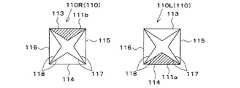
第1マーカ部材110Lと第2マーカ部材110Rとは互いに異なるマーカとして識別が可能であって、マーカを構成する枠内に異なる色111a、色111bが着色されている。図4Aに示すように、第1マーカ部材110L及び第2マーカ部材110Rは、4辺を有する矩形状(四角形)である。第1マーカ部材110L及び第2マーカ部材110Rのそれぞれの境界(枠)を構成する上辺113と、下辺114とは平行であり、右辺115と左辺116とも平行であり、上辺113及び下辺114と右辺115及び左辺116とは直行している。第1マーカ部材110Lと第2マーカ部材110Rとにおいて、マーカとして認識するための交差するライン117、118を有している。 The
なお、図4Aのマーカ部材110は一例である。例えば、図4Bに示すように、第1マーカ部材110Lと第2マーカ部材110Rの枠内に、複数のライン117、118を形成してもよい。図4Bの第1マーカ部材110Lと第2マーカ部材110Rにおいても、色111a、色111bが着色されていてマーカを個別に識別することができる。
図4Cに示した第1マーカ部材110L及び第2マーカ部材110Rは、上辺113と下辺114とを含み、枠内にライン117、118が形成され、色111a、色111bが着色されている。The
The
図1、図6に示すように、トラクタ1の後部には、複数のマーカ部材110を検出するマーカ検出装置120が設けられている。マーカ検出装置120はCCDカメラ、CMOSカメラ、赤外線カメラである。マーカ検出装置120の撮像方向X1は、複数のマーカ部材110に向けられている。また、マーカ検出装置120において、画角θ1(撮像範囲)内にマーカ検出装置120の位置が設定されている。マーカ検出装置120は、例えば、キャビン9の上部に設けられている。なお、マーカ検出装置120は、マーカ部材110が検出できればよく、取付位置は限定されない。 As shown in FIGS. 1 and 6, a
図8に示すように、トラクタ1は、操舵装置11を備えている。操舵装置11は、ハンドル(ステアリングホイール)11aと、ハンドル11aの回転に伴って回転する回転軸(操舵軸)11bと、ハンドル11aの操舵を補助する補助機構(パワーステアリング機構)11cと、を有している。補助機構11cは、油圧ポンプ21と、油圧ポンプ21から吐出した作動油が供給される制御弁22と、制御弁22により作動するステアリングシリンダ23とを含んでいる。制御弁22は、制御信号に基づいて作動する電磁弁である。制御弁22は、例えば、スプール等の移動によって切り換え可能な3位置切換弁である。また、制御弁22は、操舵軸11bの操舵によっても切換可能である。ステアリングシリンダ23は、前輪7Fの向きを変えるアーム(ナックルアーム)24に接続されている。 As shown in FIG. 8, the
したがって、ハンドル11aを操作すれば、当該ハンドル11aに応じて制御弁22の切換位置及び開度が切り換わり、当該制御弁22の切換位置及び開度に応じてステアリングシリンダ23が左又は右に伸縮することによって、前輪7Fの操舵方向を変更することができる。なお、上述した操舵装置11は一例であり、上述した構成に限定されない。
トラクタ1は、測位装置40を備えている。測位装置40は、D−GPS、GPS、GLONASS、北斗、ガリレオ、みちびき等の衛星測位システム(測位衛星)により、自己の位置(緯度、経度を含む測位情報)を検出可能である。即ち、測位装置40は、測位衛星から送信された衛星信号(測位衛星の位置、送信時刻、補正情報等)を受信し、衛星信号に基づいて、トラクタ1の位置(例えば、緯度、経度)、即ち、車体位置を検出する。測位装置40は、受信装置41と、慣性計測装置(IMU:Inertial Measurement Unit)42とを有している。受信装置41は、アンテナ等を有していて測位衛星から送信された衛星信号を受信する装置であり、慣性計測装置42とは別に走行車体3に取付けられている。この実施形態では、受信装置41は、走行車体3、即ち、キャビン9に取付けられている。なお、受信装置41の取付箇所は、実施形態に限定されない。Therefore, when the
The
慣性計測装置42は、加速度を検出する加速度センサ、角速度を検出するジャイロセンサ等を有している。走行車体3、例えば、運転席10の下方に設けられ、慣性計測装置42によって、走行車体3のロール角、ピッチ角、ヨー角等を検出することができる。
なお、上述した実施形態では、連結部8は、スイングドローバであったが、図8に示すように、昇降装置であってもよい。連結部8が昇降装置である場合について説明する。連結部8は、リフトアーム25a、ロアリンク25b、トップリンク25c、リフトロッド25d、リフトシリンダ25eを有している。リフトアーム25aの前端部は、変速装置5を収容するケース(ミッションケース)の後上部に上方又は下方に揺動可能に支持されている。リフトアーム25aは、リフトシリンダ25eの駆動によって揺動(昇降)する。リフトシリンダ25eは、油圧シリンダから構成されている。リフトシリンダ25eは、制御弁37を介して油圧ポンプと接続されている。制御弁37は、電磁弁等であって、リフトシリンダ25eを伸縮させる。The
In the above-described embodiment, the connecting
ロアリンク25bの前端部は、変速装置5の後下部に上方又は下方に揺動可能に支持されている。トップリンク25cの前端部は、ロアリンク25bよりも上方において、変速装置5の後部に上方又は下方に揺動可能に支持されている。リフトロッド25dは、リフトアーム25aとロアリンク25bとを連結している。ロアリンク25bの後部及びトップリンク25cの後部には、作業装置2が連結される。リフトシリンダ25eが駆動(伸縮)すると、リフトアーム25aが昇降するとともに、リフトロッド25dを介してリフトアーム25aと連結されたロアリンク25bが昇降する。これにより、作業装置2がロアリンク25bの前部を支点として、上方又は下方に揺動(昇降)する。 The front end portion of the
図8に示すように、トラクタは、制御装置60を備えている。制御装置60は、トラクタの様々な制御を行う。制御装置60は、前後進部材61aの操作に基づいて、走行車体3を前進、後進させる。制御装置60は、イグニッションスイッチ61bの操作に基づいて、原動機4の始動、停止を行う。制御装置60は、変速切換部材61cの操作に基づいて、変速装置5の変速段(変速レベル)を変更する。制御装置60は、アクセル61dの操作に基づいて、原動機4の回転数(原動機回転数)を変更する。制御装置60は、昇降操作部材61eが操作された場合、制御弁37を制御することでリフトシリンダ25eを伸縮させ、リフトアーム25aを介して作業装置2を昇降させる。 As shown in FIG. 8, the tractor includes a
なお、制御装置60は、自動走行の制御(自動走行制御)を行ってもよい。制御装置60における自動走行では、走行車体3を予め設定された走行ルートに沿って自動走行させる。制御装置60は、少なくとも走行車体3の車体位置(測位装置40で検出された位置)と、予め設定された走行ルート(走行経路)が一致するように、即ち、走行車体3と走行ルートとが一致するように、制御弁22の切換位置及び開度を設定する。言い換えれば、自動走行モードである場合、制御装置60は、トラクタの走行位置と走行ルートとが一致するように、ステアリングシリンダ23の移動方向及び移動量(前輪の操舵方向及び操舵角)を設定する。 The
詳しくは、自動走行モードである場合、制御装置60は、走行車体3の走行位置と、走行ルートで示された位置(走行予定位置)とを比較し、走行位置と走行予定位置とが一致している場合は、操舵装置11におけるハンドル11aの操舵角及び操舵方向(前輪の操舵角及び操舵方向)を変更せずに保持する(制御弁22の開度及び切換位置を変更せずに維持する)。制御装置60は、走行位置と走行予定位置とが一致していない場合、当該走行位置と走行予定位置との偏差(ズレ量)が零となるように、操舵装置11におけるハンドル11aの操舵角及び/又は操舵方向を変更する(制御弁22の開度及び/又は切換位置を変更する)。 Specifically, in the automatic traveling mode, the
なお、上述した実施形態では、制御装置60は、自動走行制御において、走行位置と走行予定位置との偏差に基づいて操舵装置11の操舵角を変更するものであるが、走行ルートの方位とトラクタ(走行車体3)の進行方向(走行方向)の方位(車体方位)とが異なる場合、制御装置60は、車体方位が走行ルートの方位に一致するように操舵角を設定してもよい。また、制御装置60は、自動走行制御において、偏差(位置偏差)に基づいて求めた操舵角と、方位偏差に基づいて求めた操舵角とに基づいて、自動走行制御における最終の操舵角を設定してもよい。また、上記した自動走行制御における操舵角の設定方法とは異なる方法で操舵角を設定してもよい。また、制御装置60は、自動走行制御において、トラクタ(走行車体3)の実際の車速が、予め設定された走行ルートに対応する車速に一致するように、走行装置7(即ち、前輪及び/又は後輪)の回転数を制御してもよい。また、制御装置60は、走行車体3の操舵と車速とを制御することで自動走行を行っているが、車速は運転者に調整させるオートステア制御(自動操舵制御)を行ってもよく自動走行制御に限定されない。また、当然の如く、運転者がトラクタを手動操作する手動運転を行うことが可能である。 In the above-described embodiment, the
図8に示すように、トラクタ1は、状態演算装置150を備えている。状態演算装置150は、例えば、制御装置60に設けられた電気・電子回路、プログラム等から構成されている。なお、状態演算装置150は、トラクタ1に設けられた表示装置45に格納されたプログラムであっても、スマートフォン、タブレット、PDAの携帯端末151に設けられていてもよく限定されない。 As shown in FIG. 8, the
状態演算装置150は、マーカ検出装置120が検出した検出データ、例えば、撮像画像等に基づいて、作業装置2の状態を演算する。例えば、状態演算装置150は、作業装置2の状態として作業装置2の位置、即ち、マーカ部材110(第1マーカ部材110L、第2マーカ部材110R)の位置を求める。
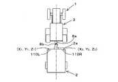
図6に示すように、状態演算装置150は、マーカ検出装置120がカメラ(CCD、CMOS等の可視光カメラ)である場合、カメラが撮像した撮像画像に基づいて、第1マーカ部材110Lの位置ML(X1、Y1、Z1)を求める。また、状態演算装置150は、カメラが撮像した撮像画像に基づいて、第2マーカ部材110Rの位置MR(X2、Y2、Z2)を求める。The
As shown in FIG. 6, when the
具体的には、状態演算装置150は、マーカ検出装置120から撮像画像を取得し、撮像画像に映った形状から第1マーカ部材110Lを認識する。状態演算装置150は、第1マーカ部材110Lを認識すると、予め設定された第1マーカ部材110Lの枠内(撮像画像内の枠内)において、第1マーカ部材110Lの面積S11、S12、S13、S21、S22、S23、S31、S32、S33を求め、互いの面積S11、S12、S13、S21、S22、S23、S31、S32、S33に基づいて第1マーカ部材110Lの姿勢ML(r11r12、r13、r21、r22、r23、r31、r32、r33)、即ち、3軸方向(X軸、Y軸、Z軸)の姿勢を求める。例えば、第1マーカ部材110Lの面積S11、S12、S13、S21、S22、S23、S31、S32、S33が同じである場合、状態演算装置150は、基準の3軸(X軸、Y軸、Z軸)と同じである。Specifically, the
また、状態演算装置150は、マーカ検出装置120から第1マーカ部材110Lまでの焦点距離(被写体距離)と、第1マーカ部材110Lの姿勢MLとから第1マーカ部材110Lの位置ML(X1、Y1、Z1)を求める。
また、状態演算装置150は、第2マーカ部材110Rを認識すると、予め設定された第2マーカ部材110Rの枠内(撮像画像内の枠内)において、第2マーカ部材110Rの面積S41、S42、S43、S51、S52、S53、S61、S62、S63を求め、互いの面積S41、S42、S43、S51、S52、S53、S61、S62、S63から第2マーカ部材110Rの姿勢RR(r41r42、r43、r51、r52、r53、r61、r62、r63)RL、即ち、3軸方向(X軸、Y軸、Z軸)の姿勢を求める。例えば、第2マーカ部材110Rの面積S41、S42、S43、S51、S52、S53、S61、S62、S63が同じである場合、状態演算装置150は、基準の3軸(X軸、Y軸、Z軸)と同じであり、傾いていないことになる。Further, the
When the state calculation device 150 recognizes the second marker member 110R, the area S 41 , S of the
また、状態演算装置150は、マーカ検出装置120から第2マーカ部材110Rまでの焦点距離(被写体距離)と、第2マーカ部材110Rの姿勢RRとから、第2マーカ部材110Rの位置MR(X2、Y2、Z2)を求める。なお、図6に示すように、トラクタ1(作業装置2)を停止した状態においてX方向は前後方向(進行方向)であり、Y方向は左右方向(幅方向)であり、Z方向は高さ方向(垂直方向)である。Further, the
以上のように、状態演算装置150は、第1マーカ部材110Lの位置ML(X1、Y1、Z1)、第2マーカ部材110Rの位置MR(X2、Y2、Z2)を求めることができる。即ち、状態演算装置150は、作業装置2において、左上部の位置ML(X1、Y1、Z1)、右上部の位置MR(X2、Y2、Z2)を求めることができる。これによれば、図7A及び図7Bに示すように、トラクタ1にて作業装置2を牽引しながら作業を行っている状況において、作業装置2の前部の位置ML,MRを三次元で把握することができる。As described above, the
図7Aに示すように、状態演算装置150が、作業装置2の左上部の位置ML(X1、Y1、Z1)と、右上部の位置MR(X2、Y2、Z2)とを求めた場合において、位置X1と位置X2とが一致している場合は、作業装置2は前後方向に斜めにならずに走行している。図7Bに示すように、状態演算装置150が、作業装置2の左上部の位置ML(X1、Y1、Z1)と、右上部の位置MR(X2、Y2、Z2)とを求めた場合において、少なくとも位置X1が位置X2よりも前方に位置している場合は、作業装置2は走行車体3に対して左側が先行して走行している。状態演算装置150が、作業装置2の左上部の位置ML(X1、Y1、Z1)と、右上部の位置MR(X2、Y2、Z2)とを求めた場合において、少なくとも位置X2が位置X1よりも前方に位置している場合は、作業装置2は走行車体3に対して右側が先行して走行している。As shown in FIG. 7A, the
なお、状態演算装置150は、作業装置2の状態として走行車体3と作業装置2との相対位置を演算してもよい。表示装置45又は携帯端末151を所定の操作を行うと、状態演算装置150は、設定画面M1が表示装置45又は携帯端末151に表示される。設定画面M1は、トラクタ1を模した図形D1と、作業装置2を模した図形D2が表示される。また、設定画面M1は、X方向の入力部141と、Y方向の入力部142とを含んでいる。入力部141には、測位装置40からマーカ検出装置120までの前後方向(X方向の距離)X10を入力可能である。また、入力部142は、測位装置40からマーカ検出装置120までの幅方向(Y方向の距離)Y10を入力可能である。例えば、測位装置40に対してマーカ検出装置120が左側又は右側にオフセットしている場合に、入力部142にオフセット量(Y方向の距離)を入力する。 The
このように、入力部141、142にX方向の距離X10及び幅方向(Y方向の距離)Y10を入力した場合、測位装置40は、当該測位装置40が検出した車体位置(第1位置)に、X方向の距離X10及び幅方向(Y方向の距離)Y10に対応する緯度、経度を加減算することによって、マーカ検出装置120の位置(緯度、経度)を求めることができる。状態演算装置150は、マーカ検出装置120の位置である第2位置を取得する一方、上述したように、作業装置2の前部の位置ML,MRを求める。 In this way, when the distance X10 in the X direction and the width direction (distance in the Y direction) Y10 are input to the
ここで、状態演算装置150は、マーカ検出装置120から第1マーカ部材110Lまでの焦点距離(被写体距離)と、第1マーカ部材110Lの位置(作業装置2の前部の位置ML)とに基づいて、第1マーカ部材110Lの位置(作業装置2の前部の位置ML)を緯度、経度に換算することにより、作業装置2の前部の位置MLを緯度、経度に換算した第1装置位置(装置位置)を求めることができる。 Here, the
また、状態演算装置150は、マーカ検出装置120から第2マーカ部材110Rまでの焦点距離(被写体距離)と、第2マーカ部材110Rの位置(作業装置2の前部の位置MR)とに基づいて、第2マーカ部材110Rの位置(作業装置2の前部の位置MR)を緯度、経度に換算することにより、作業装置2の前部の位置MRを緯度、経度に換算した第2装置位置(装置位置)を求めることができる。 Further, the
つまり、測位装置40が測位した第1位置及びマーカ検出装置120の第2位置によって、地上(圃場内)における作業装置2の前部の装置位置(第1装置位置、第2装置位置)を求めることができる。また、装置位置(第1装置位置、第2装置位置)と、マーカ検出装置120の第2位置とによって、走行車体3と作業装置2との互いの相対位置を把握することができる。 That is, the device positions (first device position, second device position) of the front part of the
さて、トレーラ以外の作業装置2を例にあげ、作業装置2の位置及び姿勢についても説明する。
図9A〜図9Cに示す作業装置2は昇降装置に連結可能な作業装置であって、例えば、散布装置の一例である。作業装置2は、昇降装置のトップリンク25cに連結される第1連結部31と、ロアリンク25bに連結される連結部32、33とを備えている。また、作業装置2の左部及び右部には、散布を行う散布ノズル34が設けられていて、肥料、薬剤等の散布を行うことができる。なお、散布ノズル34は、図示省略の配管に接続されていて、ポンプ等によって配管内に贈られた散布物(肥料、薬剤)を散布することができる。Now, taking a working
The
図9Aに示すように、状態演算装置150が、作業装置2の左上部の位置ML(X1、Y1、Z1)と、右上部の位置MR(X2、Y2、Z2)とを求めた場合において、垂直方向のZ1、Z2が同じである場合、作業装置2は地面(圃場)に対して水平である。
図9Bに示すように、状態演算装置150が、作業装置2の左上部の位置ML(X1、Y1、Z1)と、右上部の位置MR(X2、Y2、Z2)とを求めた場合において、垂直方向のZ2がZ1よりも高い場合、作業装置2は角度θ2だけ傾いていて、右上がりになっている。As shown in FIG. 9A, the
As shown in FIG. 9B, the
図9Cに示すように、状態演算装置150が、作業装置2の左上部の位置ML(X1、Y1、Z1)と、右上部の位置MR(X2、Y2、Z2)とを求めた場合において、垂直方向のZ1がZ2よりも高い場合、作業装置2は角度θ3だけ傾いていて、左上がりになっている。
以上のように、状態演算装置150によって、位置、姿勢を求めることができ、作業装置2のロール角、ピッチ角、ヨー角と、走行車体3に対する作業装置2の位置を求めることができる。状態演算装置150の状態(位置、姿勢)は、表示装置45等に表示してもよい。また、状態演算装置150の状態(位置、姿勢)に応じて、制御装置60によってトラクタ1を制御してもよい。As shown in FIG. 9C, the
As described above, the position and posture can be obtained by the
作業車両1は、作業装置2を連結する連結部8を有する走行車体3と、作業装置2に設けられたマーカ部材110と、走行車体3に設けられ且つ、マーカ部材110を検出するマーカ検出装置120と、マーカ検出装置120が検出した検出データに基づいて、作業装置2の状態を演算する状態演算装置150と、を備えている。これによれば、マーカ部材110を作業装置2に設けることによって、作業装置2の位置や姿勢などの状態を簡単に把握することができる。 The
状態演算装置150は、作業装置2の状態として作業装置2の位置を演算する。これによれば、作業装置2の位置を簡単に把握することができ、圃場で農作業を行ったり、果樹園で農作業を行う場合に、作業装置2に測位衛星からの信号に基づいて位置を検出する測位装置を設けなくても、作業装置2がどこの位置にあるのかを把握することができる。また、作業装置2に測位装置を設けた場合であっても測位衛星の信号の受信強度が低い場合であっても、測位装置の代わりに位置を把握することができる。 The
状態演算装置150は、作業装置2の状態として作業装置2の姿勢を演算する。これによれば、作業装置2の3方向の姿勢(ロール角、ピッチ角、ヨー角)を把握することが可能となる。
状態演算装置150は、作業装置2の状態として走行車体3と作業装置2との相対位置を演算する。これによれば、作業中などに、作業装置2がどれだけ走行車体3から離れているかを把握することができる。言い換えれば、作業装置2が走行車体3に近接している状態であるか離間しているかの度合いを把握することができる。The
The
作業車両1は、走行車体3は、当該走行車体3の位置である車体位置を測位する測位装置40を備え、状態演算装置150は、測位位置で演算された車体位置と、作業装置2の状態とに基づいて、作業装置2の位置である装置位置を演算する。これによれば、測位装置が演算した車体位置を用いて、緯度、経度の緯度、経度を把握することができる。
マーカ検出装置120は、マーカ部材110を撮像する撮像装置である。これによれば、簡単に作業装置2の状態を求めることができる。In the
The
作業車両1の走行管理システムは、走行車体3に連結された作業装置2に設けられたマーカ部材110と、走行車体3に設けられ且つ、マーカ部材110を検出するマーカ検出装置120と、マーカ検出装置120が検出した検出データに基づいて、作業装置2の状態を演算する状態演算装置150と、を備えている。これによれば、マーカ部材110を作業装置2に設けることによって、作業装置2の位置や姿勢などの状態を簡単に把握することができる。 The travel management system of the
作業車両1の走行管理システムは、走行車体3の位置である車体位置を測位する測位装置を備え、状態演算装置150は、測位位置で演算された車体位置と、作業装置2の状態とに基づいて、作業装置2の位置である装置位置を演算する。これによれば、作業中などに、作業装置2がどれだけ走行車体3から離れているかを把握することができる。言い換えれば、作業装置2が走行車体3に近接している状態であるか離間しているかの度合いを把握することができる。 The travel management system of the
今回開示された実施の形態はすべての点で例示であって制限的なものではないと考えられるべきである。本発明の範囲は上記した説明ではなくて特許請求の範囲によって示され、特許請求の範囲と均等の意味及び範囲内でのすべての変更が含まれることが意図される。 It should be considered that the embodiments disclosed this time are exemplary in all respects and not restrictive. The scope of the present invention is shown by the scope of claims rather than the above description, and it is intended to include all modifications within the meaning and scope equivalent to the scope of claims.
1 :作業車両
2 :作業装置
3 :走行車体
8 :連結部
110 :マーカ部材
120 :マーカ検出装置
150 :状態演算装置
ML :姿勢
RR :姿勢1: Work vehicle 2: Work device 3: Traveling vehicle body 8: Connecting part 110: Marker member 120: Marker detection device 150: State calculation device ML: Attitude RR: Attitude
Claims (12)
Translated fromJapanese前記作業装置に設けられたマーカ部材と、
前記走行車体に設けられ且つ、前記マーカ部材を検出するマーカ検出装置と、
前記マーカ検出装置が検出した検出データに基づいて、前記作業装置の状態を演算する状態演算装置と、
を備えている作業車両。A traveling vehicle body having a connecting portion for connecting work devices,
The marker member provided in the work device and
A marker detection device provided on the traveling vehicle body and detecting the marker member,
A state calculation device that calculates the state of the work device based on the detection data detected by the marker detection device, and a state calculation device that calculates the state of the work device.
A work vehicle equipped with.
前記状態演算装置は、前記測位位置で演算された車体位置と、前記作業装置の状態とに基づいて、前記作業装置の位置である装置位置を演算する請求項1〜4のいずれかに記載の作業車両。The traveling vehicle body includes a positioning device for positioning the vehicle body position, which is the position of the traveling vehicle body.
The state calculation device according to any one of claims 1 to 4, wherein the state calculation device calculates the device position, which is the position of the work device, based on the vehicle body position calculated at the positioning position and the state of the work device. Work vehicle.
前記走行車体に設けられ且つ、前記マーカ部材を検出するマーカ検出装置と、
前記マーカ検出装置が検出した検出データに基づいて、前記作業装置の状態を演算する状態演算装置と、
を備えている作業車両の走行管理システム。A marker member provided on a work device connected to a traveling vehicle body, and
A marker detection device provided on the traveling vehicle body and detecting the marker member,
A state calculation device that calculates the state of the work device based on the detection data detected by the marker detection device, and a state calculation device that calculates the state of the work device.
A work vehicle travel management system equipped with.
前記状態演算装置は、前記測位位置で演算された車体位置と、前記作業装置の状態とに基づいて、前記作業装置の位置である装置位置を演算する請求項7〜10のいずれかに記載の作業車両の走行管理システム。A positioning device for positioning the vehicle body position, which is the position of the traveling vehicle body, is provided.
The state calculation device according to any one of claims 7 to 10, wherein the state calculation device calculates the device position, which is the position of the work device, based on the vehicle body position calculated at the positioning position and the state of the work device. Travel management system for work vehicles.
Priority Applications (4)
| Application Number | Priority Date | Filing Date | Title |
|---|---|---|---|
| JP2019239899AJP7271416B2 (en) | 2019-12-27 | 2019-12-27 | Work vehicle and travel management system for work vehicle |
| US17/116,026US11514601B2 (en) | 2019-12-27 | 2020-12-09 | Working vehicle and traveling management system for the working vehicle |
| EP20212790.8AEP3841860B1 (en) | 2019-12-27 | 2020-12-09 | Working vehicle, traveling management system for the working vehicle, and method for determining a status of a working vehicle |
| CN202011478297.4ACN113044050B (en) | 2019-12-27 | 2020-12-15 | Work vehicle and travel management system for work vehicle |
Applications Claiming Priority (1)
| Application Number | Priority Date | Filing Date | Title |
|---|---|---|---|
| JP2019239899AJP7271416B2 (en) | 2019-12-27 | 2019-12-27 | Work vehicle and travel management system for work vehicle |
Publications (2)
| Publication Number | Publication Date |
|---|---|
| JP2021106558Atrue JP2021106558A (en) | 2021-07-29 |
| JP7271416B2 JP7271416B2 (en) | 2023-05-11 |
Family
ID=73789952
Family Applications (1)
| Application Number | Title | Priority Date | Filing Date |
|---|---|---|---|
| JP2019239899AActiveJP7271416B2 (en) | 2019-12-27 | 2019-12-27 | Work vehicle and travel management system for work vehicle |
Country Status (4)
| Country | Link |
|---|---|
| US (1) | US11514601B2 (en) |
| EP (1) | EP3841860B1 (en) |
| JP (1) | JP7271416B2 (en) |
| CN (1) | CN113044050B (en) |
Cited By (2)
| Publication number | Priority date | Publication date | Assignee | Title |
|---|---|---|---|---|
| JP2023065065A (en)* | 2021-10-27 | 2023-05-12 | 国立研究開発法人農業・食品産業技術総合研究機構 | Agricultural machine, agricultural machine system, agricultural machine connection method and program |
| WO2024111778A1 (en)* | 2022-11-23 | 2024-05-30 | 엘에스엠트론 주식회사 | Work vehicle control system |
Families Citing this family (4)
| Publication number | Priority date | Publication date | Assignee | Title |
|---|---|---|---|---|
| US12181604B2 (en) | 2020-11-10 | 2024-12-31 | Deere & Company | Work vehicle perception systems and rear modules |
| US12015836B2 (en)* | 2020-11-10 | 2024-06-18 | Deere & Company | Work vehicle perception systems and front modules |
| CN114040363B (en)* | 2021-11-05 | 2023-03-10 | 三一专用汽车有限责任公司 | Vehicle data interaction method and device and operation machine |
| GB202217370D0 (en)* | 2022-11-21 | 2023-01-04 | Agco Int Gmbh | Agricultural machine monitoring |
Citations (7)
| Publication number | Priority date | Publication date | Assignee | Title |
|---|---|---|---|---|
| JPH09103109A (en)* | 1995-10-12 | 1997-04-22 | Iseki & Co Ltd | Connecting device for work equipment in tractor |
| JP4315917B2 (en)* | 2005-02-09 | 2009-08-19 | 株式会社クボタ | Inclination angle measuring device |
| US20110050903A1 (en)* | 2009-04-08 | 2011-03-03 | Topcon Positioning Systems, Inc. | Method for determining position and orientation of vehicle trailers |
| JP2012166647A (en)* | 2011-02-14 | 2012-09-06 | Panasonic Corp | Image processing apparatus, and tractor |
| EP3300558A1 (en)* | 2016-09-29 | 2018-04-04 | Robert Bosch GmbH | Device and method for governing the operation of a hydraulically actuated towing device on a vehicle |
| US20180202804A1 (en)* | 2017-01-19 | 2018-07-19 | Agjunction Llc | Low cost implement positioning |
| JP2019087875A (en)* | 2017-11-07 | 2019-06-06 | アイシン精機株式会社 | Peripheral monitoring device |
Family Cites Families (14)
| Publication number | Priority date | Publication date | Assignee | Title |
|---|---|---|---|---|
| US4555725A (en)* | 1983-08-24 | 1985-11-26 | Deutz-Allis Corporation | Agricultural implement steering guidance system and method |
| DE19627139A1 (en)* | 1995-08-18 | 1998-01-15 | Andreas Hilker | Sensor system for control and regulation of agricultural machine or elements |
| JP5173277B2 (en)* | 2007-06-25 | 2013-04-03 | 株式会社クボタ | Paddy field machine |
| DE102015109799A1 (en)* | 2015-06-18 | 2016-12-22 | Claas E-Systems Kgaa Mbh & Co Kg | Method for synchronizing two independent, self-propelled agricultural machines |
| JP2017091246A (en)* | 2015-11-11 | 2017-05-25 | 有限会社曽田農機設計事務所 | Reaping robot and automatic reaping system using the same |
| JP6727971B2 (en) | 2016-07-19 | 2020-07-22 | 株式会社クボタ | Work vehicle |
| JP6837767B2 (en)* | 2016-07-19 | 2021-03-03 | 株式会社クボタ | Inclined driving management system for work vehicles and work vehicles |
| US20180040129A1 (en)* | 2016-08-02 | 2018-02-08 | Denso International America, Inc. | Trailer articulation calculating system and method for calculating articulation angle of trailer |
| JP6925603B2 (en)* | 2016-10-12 | 2021-08-25 | 本郷飛行機株式会社 | Attitude control system for moving objects |
| JP6869688B2 (en) | 2016-10-12 | 2021-05-12 | 株式会社クボタ | Work equipment, work vehicle, work equipment and work equipment equipped with work vehicle |
| KR101859045B1 (en)* | 2016-11-02 | 2018-05-17 | 엘지전자 주식회사 | Apparatus for providing around view and Vehicle |
| JP6919531B2 (en)* | 2017-11-30 | 2021-08-18 | 井関農機株式会社 | Work vehicle |
| DE102018203152A1 (en)* | 2018-03-02 | 2019-09-05 | Continental Automotive Gmbh | Trailer angle determination system for a vehicle |
| EP3552926A1 (en)* | 2018-04-09 | 2019-10-16 | Continental Automotive GmbH | Apparatus for determining an angle of a trailer attached to a vehicle |
- 2019
- 2019-12-27JPJP2019239899Apatent/JP7271416B2/enactiveActive
- 2020
- 2020-12-09USUS17/116,026patent/US11514601B2/enactiveActive
- 2020-12-09EPEP20212790.8Apatent/EP3841860B1/enactiveActive
- 2020-12-15CNCN202011478297.4Apatent/CN113044050B/enactiveActive
Patent Citations (7)
| Publication number | Priority date | Publication date | Assignee | Title |
|---|---|---|---|---|
| JPH09103109A (en)* | 1995-10-12 | 1997-04-22 | Iseki & Co Ltd | Connecting device for work equipment in tractor |
| JP4315917B2 (en)* | 2005-02-09 | 2009-08-19 | 株式会社クボタ | Inclination angle measuring device |
| US20110050903A1 (en)* | 2009-04-08 | 2011-03-03 | Topcon Positioning Systems, Inc. | Method for determining position and orientation of vehicle trailers |
| JP2012166647A (en)* | 2011-02-14 | 2012-09-06 | Panasonic Corp | Image processing apparatus, and tractor |
| EP3300558A1 (en)* | 2016-09-29 | 2018-04-04 | Robert Bosch GmbH | Device and method for governing the operation of a hydraulically actuated towing device on a vehicle |
| US20180202804A1 (en)* | 2017-01-19 | 2018-07-19 | Agjunction Llc | Low cost implement positioning |
| JP2019087875A (en)* | 2017-11-07 | 2019-06-06 | アイシン精機株式会社 | Peripheral monitoring device |
Cited By (3)
| Publication number | Priority date | Publication date | Assignee | Title |
|---|---|---|---|---|
| JP2023065065A (en)* | 2021-10-27 | 2023-05-12 | 国立研究開発法人農業・食品産業技術総合研究機構 | Agricultural machine, agricultural machine system, agricultural machine connection method and program |
| JP7716089B2 (en) | 2021-10-27 | 2025-07-31 | 国立研究開発法人農業・食品産業技術総合研究機構 | Agricultural machinery, agricultural machinery system, agricultural machinery connection method and program |
| WO2024111778A1 (en)* | 2022-11-23 | 2024-05-30 | 엘에스엠트론 주식회사 | Work vehicle control system |
Also Published As
| Publication number | Publication date |
|---|---|
| EP3841860B1 (en) | 2023-08-16 |
| US11514601B2 (en) | 2022-11-29 |
| JP7271416B2 (en) | 2023-05-11 |
| CN113044050A (en) | 2021-06-29 |
| EP3841860A1 (en) | 2021-06-30 |
| US20210201528A1 (en) | 2021-07-01 |
| CN113044050B (en) | 2024-06-18 |
Similar Documents
| Publication | Publication Date | Title |
|---|---|---|
| JP2021106558A (en) | Work vehicle and travel management system therefor | |
| JP6550617B2 (en) | Agricultural work vehicle | |
| KR20220039646A (en) | Automated driving systems for work vehicles | |
| KR102121646B1 (en) | Field state detection system | |
| JP7596417B2 (en) | Work Machine | |
| JP6658717B2 (en) | Work vehicle | |
| JP2020005595A (en) | Work vehicle | |
| JP7353877B2 (en) | Work vehicles and work support devices for work vehicles | |
| US20250100450A1 (en) | Video display system and work vehicle | |
| US12369508B2 (en) | Travel line creation system for agricultural machine | |
| US20240138282A1 (en) | Management system for agricultural machines | |
| US20230292645A1 (en) | Traveling assistance system for agricultural machine | |
| JP7150593B2 (en) | work vehicle | |
| JP2024038359A (en) | How to control the coupling device | |
| WO2021132355A1 (en) | Work vehicle | |
| CN216930903U (en) | Fusion Navigation Control System of Safflower Picking Robot | |
| US11965742B2 (en) | Work support system and work support device | |
| JP7387678B2 (en) | Agricultural machines | |
| JP7443209B2 (en) | Automatic driving support device | |
| US20250083521A1 (en) | Display system and work vehicle | |
| JP7322100B2 (en) | Agricultural machines | |
| WO2025142700A1 (en) | Work vehicle | |
| US20250085432A1 (en) | Sensing system, agricultural machine, and sensing device | |
| US20250315052A1 (en) | Route generation device and computer program | |
| JP2025115773A (en) | Agricultural machine support device, map creation method and computer program |
Legal Events
| Date | Code | Title | Description |
|---|---|---|---|
| A621 | Written request for application examination | Free format text:JAPANESE INTERMEDIATE CODE: A621 Effective date:20211222 | |
| A977 | Report on retrieval | Free format text:JAPANESE INTERMEDIATE CODE: A971007 Effective date:20221019 | |
| A131 | Notification of reasons for refusal | Free format text:JAPANESE INTERMEDIATE CODE: A131 Effective date:20221101 | |
| A601 | Written request for extension of time | Free format text:JAPANESE INTERMEDIATE CODE: A601 Effective date:20221216 | |
| A521 | Request for written amendment filed | Free format text:JAPANESE INTERMEDIATE CODE: A523 Effective date:20230215 | |
| TRDD | Decision of grant or rejection written | ||
| A01 | Written decision to grant a patent or to grant a registration (utility model) | Free format text:JAPANESE INTERMEDIATE CODE: A01 Effective date:20230328 | |
| A61 | First payment of annual fees (during grant procedure) | Free format text:JAPANESE INTERMEDIATE CODE: A61 Effective date:20230426 | |
| R150 | Certificate of patent or registration of utility model | Ref document number:7271416 Country of ref document:JP Free format text:JAPANESE INTERMEDIATE CODE: R150 |