JP2021104178A - Puncture instrument - Google Patents
Puncture instrumentDownload PDFInfo
- Publication number
- JP2021104178A JP2021104178AJP2019236562AJP2019236562AJP2021104178AJP 2021104178 AJP2021104178 AJP 2021104178AJP 2019236562 AJP2019236562 AJP 2019236562AJP 2019236562 AJP2019236562 AJP 2019236562AJP 2021104178 AJP2021104178 AJP 2021104178A
- Authority
- JP
- Japan
- Prior art keywords
- puncture
- protrusion
- depth
- lancet
- tip
- Prior art date
- Legal status (The legal status is an assumption and is not a legal conclusion. Google has not performed a legal analysis and makes no representation as to the accuracy of the status listed.)
- Granted
Links
- 230000007246mechanismEffects0.000abstractdescription9
- 230000006835compressionEffects0.000description17
- 238000007906compressionMethods0.000description17
- 239000008280bloodSubstances0.000description15
- 210000004369bloodAnatomy0.000description15
- 230000002093peripheral effectEffects0.000description7
- 210000000078clawAnatomy0.000description6
- 210000003811fingerAnatomy0.000description3
- 230000002950deficientEffects0.000description2
- 230000002265preventionEffects0.000description2
- 210000003813thumbAnatomy0.000description2
- 230000000007visual effectEffects0.000description2
- 230000002159abnormal effectEffects0.000description1
- 230000032683agingEffects0.000description1
- 230000004323axial lengthEffects0.000description1
- 238000005452bendingMethods0.000description1
- 238000012790confirmationMethods0.000description1
- 230000000694effectsEffects0.000description1
- 230000001771impaired effectEffects0.000description1
- 239000012780transparent materialSubstances0.000description1
Images


Landscapes
- Measurement Of The Respiration, Hearing Ability, Form, And Blood Characteristics Of Living Organisms (AREA)
Abstract
Description
Translated fromJapanese本開示は穿刺器具に関し、特にディスポーザブル型の採血用穿刺器具に関する。 The present disclosure relates to a puncture device, particularly a disposable blood collection puncture device.
皮膚表面を穿刺して、少量の血液を滲出させて採血を行う場合がある。このような採血の際に、使い捨ての穿刺器具が用いられる場合がある。使い捨ての穿刺器具は、先端に穿刺針を有するランセットが、ばねの力で付勢されてハウジングの中に収容されている。付勢力を解放することにより、ランセットの先端がハウジングから突出して皮膚表面を穿刺して、皮膚から血液を滲出させる。 Blood may be collected by puncturing the surface of the skin and exuding a small amount of blood. Disposable puncture devices may be used for such blood collection. In the disposable puncture device, a lancet having a puncture needle at the tip is urged by the force of a spring and housed in the housing. By releasing the urging force, the tip of the lancet protrudes from the housing and punctures the skin surface, causing blood to exude from the skin.
使用時に付勢力を解放できるようにランセットを保持する種々の機構が検討されている。例えば、ランセットにアーム等の可動部分を設け、可動部分をハウジングの一部に解除可能に係止する機構がある(例えば、引用文献1を参照。)。しかし、このような機構の場合、可動部分の係止を解除する際に、ランセットに横方向の力が加わるため、解放時にランセットの軸が軸方向からずれたり、変形したりして、意図せぬ軌跡で移動して穿刺時に針がぶれるという問題がある。 Various mechanisms for holding the lancet are being studied so that the urging force can be released during use. For example, there is a mechanism in which a movable portion such as an arm is provided on the lancet and the movable portion is releasably locked to a part of the housing (see, for example, Reference 1). However, in the case of such a mechanism, a lateral force is applied to the lancet when the movable part is unlocked, so that the axis of the lancet deviates from the axial direction or is deformed at the time of release, which is intentional. There is a problem that the needle moves on a non-trajectory and the needle shakes during puncture.
ランセットに対して横方向の外力を加える必要が無い構成として、ハウジング内に回動可能な係止リングを設けるものがある。この場合、係止リングが付勢状態にあるランセットを受け止めており、係止リングを回動させることによりランセットと係止リングとの係合が外れて、ランセットが係止リングを通過して先端側へ移動する(例えば、特許文献2を参照。)。このような機構とすることにより、付勢力を解放する際に、ランセットに横方向の力を加えないため、穿刺時に針がぶれにくくすることができる。 As a configuration in which it is not necessary to apply a lateral external force to the lancet, there is a configuration in which a rotatable locking ring is provided in the housing. In this case, the locking ring receives the lancet in the urged state, and by rotating the locking ring, the lancet and the locking ring are disengaged, and the lancet passes through the locking ring and is at the tip. Move to the side (see, for example, Patent Document 2). With such a mechanism, a lateral force is not applied to the lancet when the urging force is released, so that the needle can be prevented from shaking during puncture.
しかし、係止リングを有する機構において、依然として穿刺ブレが生じうることが新たに確認された。即ち、ディスポーザブル型の穿刺装置においては、小型化が求められているが、係止リングを小さくすると、係止リングを通過するランセットハブの軸を細くせざるを得ない。その一方、ディスポーザブル型の穿刺装置は、すぐに使用できるようにばねによる付勢力がランセットに加えられた状態で製造されるため、使用するまでの間に、付勢力によりランセットハブの軸が撓むように変形して曲がってしまう事象が確認された。ランセットハブの軸が曲がると、穿刺時に穿刺針が揺動し、穿刺ブレが生じやすい。 However, it was newly confirmed that puncture blurring can still occur in the mechanism having the locking ring. That is, in the disposable type puncture device, miniaturization is required, but if the locking ring is made smaller, the shaft of the lancet hub passing through the locking ring must be made thinner. On the other hand, the disposable puncture device is manufactured with a spring urging force applied to the lancet so that it can be used immediately, so that the lancet hub shaft is bent by the urging force before use. It was confirmed that the product was deformed and bent. If the shaft of the lancet hub is bent, the puncture needle swings during puncture, and puncture blurring is likely to occur.
本開示の課題は、穿刺ブレが生じにくい穿刺器具を実現できるようにすることである。 An object of the present disclosure is to make it possible to realize a puncture device that is less likely to cause puncture blurring.
本開示の穿刺器具の一態様は、穿刺針及び先端から突出するように穿刺針を保持するランセットハブを有するランセットと、ランセットを収容するハウジングと、穿刺針がハウジングから突出する方向にランセットを付勢する付勢部材とを備え、ハウジングは、ランセットハブが挿通された係止リングと、係止リングよりも先端側に設けられた穿刺深さ設定部とを有し、ランセットハブは、先端側に穿刺深さ設定部と衝突して穿刺深さを決定する深さ決定用突部を有している。 One aspect of the puncture device of the present disclosure includes a lancet having a puncture needle and a lancet hub for holding the puncture needle so as to protrude from the tip, a housing for accommodating the lancet, and a lancet in a direction in which the puncture needle protrudes from the housing. The housing has a locking ring through which the lancet hub is inserted and a puncture depth setting portion provided on the tip side of the locking ring, and the lancet hub is on the tip side. It has a depth-determining protrusion that collides with the puncture depth setting portion to determine the puncture depth.
穿刺器具の一態様によれば、ランセットハブの先端側に設けられた深さ決定用突部が穿刺深さ設定部に衝突して穿刺深さを決定する。ランセットハブの軸が撓んで曲がるように変形した場合の穿刺時に穿刺針が揺動は、穿刺深さ設定部と衝突する部分と穿刺針との相対位置に起因しており、深さ決定用突部が穿刺針から離れるほど穿刺針の揺れの可動域が大きくなり、穿刺針のブレが大きくなる。このため、ランセットハブの先端側の部分に深さ決定用突部を設けることにより、深さ決定用突部が基端側に設けられた場合と比べて、穿刺ブレの発生を抑えることができる。 According to one aspect of the puncture device, the depth-determining protrusion provided on the tip end side of the lancet hub collides with the puncture depth setting portion to determine the puncture depth. The swing of the puncture needle during puncture when the shaft of the lancet hub is bent and deformed is due to the relative position between the part that collides with the puncture depth setting part and the puncture needle, and the depth determination protrusion. The farther the part is from the puncture needle, the larger the range of motion of the puncture needle swings, and the greater the blurring of the puncture needle. Therefore, by providing the depth-determining protrusion on the tip end side of the lancet hub, it is possible to suppress the occurrence of puncture blur as compared with the case where the depth-determining protrusion is provided on the base end side. ..
穿刺器具の一態様において、深さ決定用突部は穿刺動作において係止リングを通過可能な位置に設けることができる。このようにすることで、使用者は穿刺予定部とボタンを視野に入れながら穿刺ボタンを押圧することが容易となる。また、穿刺後において深さ決定用突部が穿刺部の視認性を損なう事態を低減できる。 In one aspect of the puncture device, the depth-determining protrusion can be provided at a position where the locking ring can pass during the puncture operation. By doing so, the user can easily press the puncture button while keeping the planned puncture portion and the button in the field of view. In addition, it is possible to reduce the situation where the depth-determining protrusion impairs the visibility of the punctured portion after puncturing.
穿刺器具の一態様において、ハウジングは、穿刺深さ設定部よりも先端側に設けられた、内部を視認可能な透明性を有する皮膚当接筒部を備え、皮膚当接筒部は、穿刺深さ設定部が設けられた部分よりも肉薄とすることができる。このような構成とすることにより、血液の滲出を目視により確認する際に穿刺深さ設定部が視認性を阻害することを防止することができる。 In one aspect of the puncture device, the housing is provided with a transparent skin contact tube portion provided on the tip side of the puncture depth setting portion so that the inside can be visually recognized, and the skin contact tube portion is the puncture depth. It can be made thinner than the portion provided with the puncture setting portion. With such a configuration, it is possible to prevent the puncture depth setting portion from obstructing the visibility when visually confirming the exudation of blood.
穿刺器具の一態様において、皮膚当接筒部の先端から穿刺深さ設定部までの長さは、皮膚当接筒部の先端の直径よりも大きくすることができる。このような構成とすることにより、穿刺による血液の滲出をより確実に目視できる。 In one aspect of the puncture device, the length from the tip of the skin contact tube to the puncture depth setting portion can be made larger than the diameter of the tip of the skin contact tube. With such a configuration, the exudation of blood due to puncture can be more reliably visually observed.
穿刺器具の一態様は、押圧することにより穿刺動作を行わせる穿刺ボタンをさらに備え、穿刺深さ設定部の突出方向は、ボタンの押圧方向と平行であってもよい。使用者はボタンを親指で押圧する傾向があるため、穿刺後の穿刺部の確認がボタンの押圧方向と平行な視点で行われることは少ない。このため、穿刺深さ設定部が視認性を阻害する事態を低減することができる。 One aspect of the puncture device further includes a puncture button that causes a puncture operation by pressing, and the protruding direction of the puncture depth setting portion may be parallel to the pressing direction of the button. Since the user tends to press the button with his thumb, the confirmation of the punctured portion after puncture is rarely performed from a viewpoint parallel to the pressing direction of the button. Therefore, it is possible to reduce the situation where the puncture depth setting portion impairs the visibility.
本開示の穿刺器具によれば、穿刺ブレを生じにくくすることができる。 According to the puncture device of the present disclosure, puncture blurring can be less likely to occur.
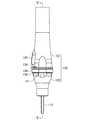
図1〜図5に示すように、本実施形態の穿刺器具は、ランセット101と、ランセット101を収容するハウジング102と、ランセット101を付勢する付勢部材である圧縮コイルばね103とを備えている。以下の説明においては、皮膚に当接させる側を先端側、その反対側を基端側という。 As shown in FIGS. 1 to 5, the puncture device of the present embodiment includes a
ランセット101は、ランセットハブ111と鋭利な先端が突出するようにランセットハブ111に取り付けられた穿刺針112とを有している。図1〜図5に示す未使用の状態において、穿刺針112の先端部は、針カバー113に覆われている。 The
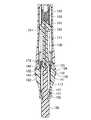
ランセットハブ111は、ロッド状であり、ランセットハブ111の基端部には、圧縮コイルばねね103を固定するばね座151が形成されている。ランセットハブ111の基端部の外周面上には、ランセットハブ111の中心軸に対して直角方向両側に突出する一対の基端側突部152が、一体形成されている。ランセットハブ111の先端部の外周面上には、ランセットハブ111の中心軸に対して直角方向両側に突出する一対の先端側突部153が一体形成されている。また、先端側突部153よりも所定寸法だけ基端側には、ランセットハブ111の中心軸に対して直角方向両側に突出する一対の深さ決定用突部154が一体形成されている。深さ決定用突部154はランセットハブ111の軸方向中心に比して先端側に設けられている。また、穿刺針112はランセットハブ内において深さ決定用突部154が位置する部分より基端側に延びており、ランセットハブの強度を向上させている。 The
先端側突部153の突出方向と、深さ決定用突部154の突出方向とは、互いに異なっている。本実施形態では、先端側突部153の突出方向と、深さ決定用突部154の突出方向とが、互いに中心軸回りで90°ずれている。なお、本実施形態において、先端側突部153の突出方向と、基端側突部152の突出方向とは、中心軸回りで一致しているが、先端側突部153の突出方向と、基端側突部152の突出方向とは一致していなくてもよい。 The protruding direction of the tip-
針カバー113は、ランセットハブ111と中心軸が一致したロッド状であり、ランセットハブ111の先端に一体に形成されている。ランセットハブ111と針カバー113との境界部分は外径寸法が小さくされたくびれ状のねじ切部155となっており、ランセットハブ111に対して針カバー113を中心軸回りにねじることによりねじ切部155をねじ切って、針カバー113を手作業でランセットハブ111から取り外すことができる。針カバー113をランセットハブ111から取り外すことにより、針カバー113により覆われていた穿刺針112の先端部を露出させることができる。 The
針カバー113の先端部分は、扁平な把持部156となっており、把持部156の基端部には、突起157及び舌片状の弾性爪158が幅方向両側部から突出して形成されている。 The tip portion of the
ランセット101は、中心軸をハウジング102の中心軸に一致させてハウジング102に収容されている。ハウジング102は、ハウジング本体121と、ハウジング本体121の先端側に取り付けられたキャップ体122とを有している。 The
ハウジング本体121は、基端が天板部により閉じられ、先端が開口した略円筒形状であり、先端が基端よりも若干大径になっている。ハウジング本体121の天板部には、内面中央から先端側に突出するばね座126が設けられている。また、ハウジング本体121の内壁には、軸方向に延びる一対の本体側ガイド溝130が設けられている。本体側ガイド溝130は、ランセットハブ111に設けられた基端側突部152を軸方向にガイドできるように周方向幅及び径方向深さが設定されている。本体側ガイド溝130に基端側突部152がはめ込まれてスライドすることにより、ランセットハブ111の軸方向の移動をスムーズにすると共に、ランセットハブ111が軸周りに回転しないようにできる。 The
ハウジング本体121の先端付近には、穿刺ボタンである操作片124が形成されている。操作片124は、ハウジング本体121の周壁に形成された貫通窓134内に配置されており、ハウジング本体121の周壁に部分的に連結されている。操作片124を手指で押すことにより、連結部が弾性変形して、操作片124はハウジング本体121の内側に向かって変位する。 An
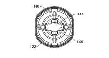
ハウジング本体121の先端には、キャップ体122を連結するための連結リブ136が一体に形成されている。図6〜図9に示すように、キャップ体122の基端部には、連結リブ136を受け入れる連結リング138が一体に形成されている。連結リング138は、キャップ体122の外周面上に突設された連結部141によって、キャップ体122に連結支持されている。本実施形態においては、連結リブ136及び連結部141は、それぞれ4つ設けられており、連結リブ136の間の位置に連結部141を位置合わせして、連結リブ136を連結リング138に係合させる。これにより、ハウジング本体121とキャップ体122とは、軸方向に位置決め固定されると共に、キャップ体122がハウジング本体121に対して回動しないように位置決め固定される。 A connecting
キャップ体122は、連結リング138よりも基端側に突出した支持筒部142を有している。支持筒部142には、ランセットハブ111に設けられた一対の先端側突部153を受け入れる切欠き溝144が設けられている。支持筒部142における切欠き溝144とずれた位置には、ランセットハブ111に設けられた一対の深さ決定用突部154を受け入れるキャップ側ガイド溝146が設けられている。キャップ側ガイド溝146は、キャップ体122の先端から所定の長さ基端側に離れた位置まで延びている。 The
切欠き溝144とキャップ側ガイド溝146との位置関係は、ランセットハブ111に設けられた先端側突部153と深さ決定用突部154との位置関係と一致している。また、切欠き溝144は、針カバー113に設けられた突起157及びランセットハブ111に設けられた先端側突部153を受け入れるように周方向幅寸法及び径方向深さ寸法が規定されている。キャップ側ガイド溝146は、ランセットハブ111に設けられた深さ決定用突部154を受け入れるように周方向幅寸法及び径方向深さ寸法が規定されている。 The positional relationship between the
キャップ体122の先端部における切欠き溝144を延長した位置には、針カバー113に設けられた突起157及び弾性爪158と係合するカバー係止用突起147が設けられている。キャップ側ガイド溝146の先端には、深さ決定用突部154が衝突する穿刺深さ設定部163が設けられている。穿刺深さ設定部163は、ハウジング102の中心軸に対して垂直に突出する突部であり、基端面に深さ決定用突部154の先端面が衝突する。本実施形態において、穿刺深さ設定部163の周りには深さ決定用突部154を穿刺深さ設定部163に確実に衝突させるべく深さ決定用突部154をガイドする案内壁が設けられている。穿刺深さ設定部163を深さ決定用突部154をガイドするキャップ側ガイド溝146の先端に設けることにより、深さ決定用突部154が穿刺深さ設定部163に確実に衝突するようにガイドすることができる。一方、キャップ側ガイド溝146の基端はテーパー状に幅が大きく形成されており、深さ決定用突部154がキャップ側ガイド溝146内に導入されやすくしている。穿刺深さ設定部163は衝突時に深さ決定用突部154が通過しないようにカバー係止用突起に比して大きく内側に突出している。但し、キャップ側ガイド溝146は必要に応じて設ければよく、設けなくてもよい。また、穿刺深さ設定部163をカバー係止用突起に比して大きく内側に突出させなくてもよい。 At the position where the
ハウジング102内には、付勢部材である圧縮コイルばね103及び係止リング172が収容されている。圧縮コイルばね103は、ハウジング本体121の天板部に設けられたばね座126と、ランセットハブ111のばね座151との間に嵌め合わされて固定されている。ランセットハブ111を基端側に変位させた位置では、圧縮コイルばね103が圧縮変形され、ランセットハブ111をハウジング102から先端側へ押し出す方向に圧縮変形に伴う付勢力が加わる。 A
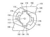
図10に示すように、係止リング172は、中央部にランセットハブ111が挿通される貫通孔を有する略円形のリング形状であり、キャップ体122の支持筒部142に回動可能に取り付けられている。係止リング172は、基端側に設けられた厚みがある内フランジ状の係合部175と、先端側に突出する一対の当接脚部174とを有している。本実施形態において当接脚部174は、支持筒部142の周りに設けられた4つの連結部141同士の間に差し入れられている。係止リング172を回動させた際に、当接脚部174が連結部141に対して周方向で当接するため、支持筒部142上での係止リング172の周方向の回動許容範囲は45°よりも小さくなる。 As shown in FIG. 10, the
内フランジ状の係合部175の内周面には、一対の第1通過溝176及び一対の第2通過溝178が、それぞれ径方向に対向して形成されている。第1通過溝176及び第2通過溝178は、それぞれ係合部175の軸方向全長に亘って直線的に延びている。 A pair of first passing
係合部175の内径寸法は、ランセットハブ111及び針カバー113の外径寸法よりも僅かに大きくされており、ランセットハブ111及び針カバー113に対して係止リング172が外挿されている。係合部175の第1通過溝176は、ランセットハブ111の先端側突部153よりも僅かに大きな断面形状を有し、先端側突部153は第1通過溝176内を軸方向に移動可能である。一方、係合部175の第2通過溝178は、ランセットハブ111の深さ決定用突部154よりも僅かに大きな断面形状とされており、深さ決定用突部154は第2通過溝178内を軸方向に移動可能である。 The inner diameter of the engaging
係止リング172における、一対の第1通過溝176同士を結んだ直線と、一対の第2通過溝178同士を結んだ直線とのなす角度(交角)は、ランセットハブ111における一対の先端側突部153の突出方向と、一対の深さ決定用突部154の突出方向とのなす角度(交角)と異なっている。具体的に、一対の第1通過溝176同士を結んだ直線と、一対の第2通過溝178同士を結んだ直線とのなす角度は、約60°であり、先端側突部153の突出方向と、一対の深さ決定用突部154の突出方向とのなす角度は90°である。このため、係止リング172に挿通されたランセットハブ111は、先端側突部153と第1通過溝176とが位置合わせされた状態では、深さ決定用突部154が第2通過溝178を通過できない。一方、深さ決定用突部154と第2通過溝178とが位置合わせされた状態では、先端側突部153が第1通過溝176を通過できない。 The angle (intersection angle) between the straight line connecting the pair of first passing
ランセットハブ111における先端側突部153の基端面と、深さ決定用突部154の先端面との間隔は、係合部175の厚さよりも僅かに大きい。このため、先端側突部153が第1通過溝176を通り抜けて係合部175よりも先端側に位置し、深さ決定用突部154が係合部175よりも基端側に位置した状態とすることができる。この状態とすることによりランセットハブ111に外挿された係止リング172をランセットハブ111に対して回動させることができる。 The distance between the base end surface of the tip
係止リング172の外周面には、一対の押圧片180が、径方向両側に突出して一体形成されている。この押圧片180は、係止リング172を軸方向視した場合において不等辺直角三角形状であり、その斜辺に相当する面は、係止リング172の中心軸回りで傾斜した押圧傾斜面182となる。一対の押圧片180は、係止リング172を支持筒部142に装着した状態において、ハウジング本体121の操作片124の内方に位置するように位置合わせされている。操作片124を手指でハウジング102内に押し込むことにより、操作片124の周方向一方の端部が押圧傾斜面182に押し付けられ、押圧する。押圧傾斜面182の傾斜角度に応じて発揮される分力作用に基づいて、操作片124の押圧力が係止リング172を回動させる。 A pair of
図4及び図5に示す、針カバー113が取り付けられた未使用の状態では、針カバー113に形成された突起157と弾性爪158の間にキャップ体122のカバー係止用突起147が挟まれて係止されている。この状態においてランセット101は、付勢部材である圧縮コイルばね103を圧縮変形させて、ランセットハブ111の深さ決定用突部154が係止リング172と当接しないハウジング本体121の基端側まで押し込まれている。このため、圧縮コイルばね103の付勢力は、針カバー113の突起157及び弾性爪158と、キャップ体122のカバー係止用突起147との係合により受け止められている。 In the unused state in which the
未使用の状態においては、係止リング172は、第1通過溝176が支持筒部142の切欠き溝144と位置合わせされており、ランセットハブ111の先端側突部153は、係止リング172の第1通過溝176と、支持筒部142の切欠き溝144との間に跨がって位置している。このため、操作片124を操作しても、係止リング172はランセットハブ111に対して回動しない。 In the unused state, the first passing
針カバー113が取り付けられた未使用の穿刺器具100を使用する場合には、まずハウジング102を一方の手で把持し、他方の手で針カバー113を摘まみ、針カバー113を回転させる。これにより、針カバー113の突起157及び弾性爪158を、キャップ体122のカバー係止用突起147から離脱させる。さらに、針カバー113をねじ切部155でねじ切ってランセットハブ111から分離し、針カバー113をキャップ体122から抜き取る。 When using the unused puncture device 100 to which the
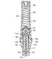
針カバー113を抜き取ると、ランセットハブ111は、圧縮コイルばね103の付勢力で先端側に移動する。これにより、図11〜図13に示す、ランセットハブ111の深さ決定用突部154が、係止リング172の係合部175の基端面に当接した穿刺準備状態となる。本実施形態においては、穿刺準備状態においては、圧縮コイルばね103の付勢力は、深さ決定用突部154と係止リング172の係合部175との当接により受け止められる。穿刺準備状態においては、先端側突部153は、第1通過溝176を通り抜けて先端側に位置し、係止リング172は回動可能な状態となる。 When the
穿刺準備状態の穿刺器具100の操作片124を手指で押し込むことにより、係止リング172を回動させると、図14〜図16に示すように、係止リング172の第2通過溝178の位置が、係止リング172の基端面に当接していたランセットハブ111の深さ決定用突部154の位置と一致する。圧縮コイルばね103の付勢力により、深さ決定用突部154が、第2通過溝178を通過して、穿刺深さ設定部163に衝突するまで先端側へ移動する。これにより、穿刺針112の先端がキャップ体122の先端開口から所定の長さだけ突出し、穿刺が行われる。なお、キャップ体122の穿刺深さ設定部163よりも先端側に設けられたカバー係止用突起147は、ランセットハブ111の先端側突部153の通過を妨げない大きさに設計されている。また、ランセットハブ111の基端側突部152は、穿刺位置においても係止リング172の基端に当接しないように設計されており、本体側ガイド溝130にも基端側突部152が衝突する突起等は設けられていない。 When the
付勢力が解放された圧縮コイルばね103は、その自由長を超えて伸張した後、自由長に復元する。圧縮コイルばね103の軸方向両端部は、ハウジング本体121のばね座126とランセットハブ111のばね座151とにそれぞれ固定されているため、穿刺後のランセット101は、圧縮コイルばね16の復元力により基端側に引き戻され、図17及び図18に示す使用済み状態となる。使用済み状態において、ランセット101は圧縮コイルばね103の自由長により決定される位置に保持される。 The
穿刺装置は、所定の穿刺深さを実現すると共に、穿刺の際に皮膚に生じる傷を必要最小限にすることが求められる。穿刺針を皮膚に対して垂直に侵入させ、垂直に抜き去った場合に、皮膚に生じる傷を最も小さくすることができる。しかし、穿刺の際にはブレが生じるため、穿刺針が皮膚に浸入する際及び抜き去る際にその角度が変動し、傷口が大きくなり、穿刺による痛みも大きくなる。穿刺の際のブレをできるだけ小さくするために、各部のクリアランスをできるだけ小さくすることが考えられるが、経時変化によりランセットハブが撓んで変形してしまうことを考慮すれば、ある程度大きなクリアランスが必要となる。 The puncture device is required to achieve a predetermined puncture depth and to minimize the damage to the skin during puncture. When the puncture needle is inserted vertically into the skin and pulled out vertically, the damage caused to the skin can be minimized. However, since blurring occurs during puncture, the angle of the puncture needle fluctuates when it enters the skin and when it is removed, the wound becomes large, and the pain caused by the puncture also increases. It is conceivable to make the clearance of each part as small as possible in order to minimize the blurring during puncture, but considering that the lancet hub bends and deforms due to aging, a certain amount of clearance is required. ..
ランセットハブの基端側に穿刺深さ設定用突部を設けた場合、係止リングとの干渉を考慮する必要が無い一方で、ランセットハブの軸が曲がった場合、穿刺深さ設定用突部が穿刺深さ設定部に衝突した際の揺動角度が大きくなり、その結果、穿刺の際にブレが生じ、痛みが大きくなる。 When a puncture depth setting protrusion is provided on the base end side of the lancet hub, it is not necessary to consider interference with the locking ring, but when the lancet hub shaft is bent, the puncture depth setting protrusion is provided. The swing angle becomes large when the puncture depth setting portion collides with the puncture depth setting portion, and as a result, blurring occurs at the time of puncture and the pain becomes large.
本実施形態の穿刺装置は、係止リング172を通過して先端側に移動する深さ決定用突部154をハウジングに設けた穿刺深さ設定部163に衝突させている。深さ決定用突部154は、穿刺の際に係止リング172を通過するランセットハブ111の先端側に位置するため、圧縮コイルばね103の付勢力による撓み変形の影響を受けにくく、穿刺の際にブレが生じにくい。 In the puncture device of the present embodiment, the
さらに、深さ決定用突部154がランセットハブの先端側にあることで、ランセットハブの軸が曲がった場合の深さ決定用突部154の先端面は、深さ決定用突部154がランセットハブの基端側にある場合に比して、大きく傾きにくい。このため、深さ決定用突部154の先端面が穿刺深さ設定部163に衝突した際に面と面が当たるまでのブレを小さくすることができる。また、穿刺準備状態において、係止リング172の基端面に当接していることで、穿刺準備状態における穿刺針の軸方向位置規制を兼ねることができ、係止リング172との干渉影響に対する考慮を最小限にすることができる
ランセットハブ111の最先端部に穿刺深さ設定用の突部を設ければ、ランセットハブ111の撓みの影響を最も小さくできる。しかし、この場合穿刺深さ設定用の突部と衝突するキャップ体122側の衝突部をキャップ体の先端近傍に設けなければならない。キャップの先端近傍に衝突部を設けると、外部からの穿刺部分の視認性が低下してしまう。使用者は穿刺後に穿刺部から血液が漏出するまでキャップ体先端を皮膚に押し当てるが、視認性が低下してしまうと血液が滲出できたか否かが判別しにくくなり、好ましくない。しかし、本実施形態においては、深さ決定用突部154を先端側突部153よりも基端側に設け、穿刺の際に係止リング172を通過するようにしている。このため、穿刺深さ設定部163を、キャップ体122の先端から所定の距離だけ基端側に離れた位置に設けることができ、外部からの穿刺部分の視認性を向上することができる。Further, since the
なお、図19に示すように、キャップ体122の先端に肉薄の皮膚当接筒部164を設けることで、視認性をさらに向上させることができる。皮膚当接筒部164の肉厚tは、少なくともキャップ体122の穿刺深さ設定部163が内側に突出している部分の最大の肉厚よりも薄く、キャップ体122の穿刺深さ設定部163よりも基端側の深さ決定用突部154が通過する部分の肉厚よりも薄いことが好ましい。また、皮膚当接筒部164の内径φを、深さ決定用突部154よりも大径とすると、穿刺後に滲出した血液の周りに十分な空間を設けることができ、滲出した血液がキャップ体122に触れてしまうような事態を生じにくくすることができる。さらに、皮膚当接筒部164の部分にはガイド用の溝部が設けられていないため、皮膚当接筒部164を透明性が高い材料により形成すれば内部の視認が容易となり、血液の滲出の状態を目視で確認することが可能となる。なお、皮膚当接筒部164の部分だけを透明することも、キャップ体122全体を透明にすることもできる。 As shown in FIG. 19, the visibility can be further improved by providing the thin skin
穿刺による血液の滲出をより確実に目視できるようにする観点から、皮膚当接筒部164の先端から穿刺深さ設定部163までの長さLは、皮膚当接筒部164の先端の内径φよりも大ききことが好ましい。また、皮膚当接筒部の先端の内径φを、深さ決定用突部154の最大幅よりも大きくすることにより、皮膚当接筒部への血液付着を抑制することができる。また、キャップ側ガイド溝146を設ける場合には、穿刺深さ設定部163をキャップ側ガイド溝146の先端に設けることが好ましい。このようにすれば、視認の詩に邪魔になるキャップ側ガイド溝146と穿刺深さ設定部163の位置が集約されて、視認性が阻害される事態を低減できる。 From the viewpoint of making it possible to more reliably see the exudation of blood due to puncture, the length L from the tip of the skin
穿刺操作時、操作片124は親指で押される傾向が高く、操作片124は、体の正面に向き合う位置から若干斜めにずれた位置に自然となる。このため、キャップ体122の周上における操作片との中心角が±25°〜65°となる角度範囲には、視認の障害となる凹凸がないことが好ましい。具体的には、穿刺深さ設定部163及びキャップ側ガイド溝146はこの角度範囲にないことが好ましく、穿刺深さ設定部163がキャップ体122の周上に相対して1対設けられている場合、一方の穿刺深さ設定部163の周方向位置と操作片124の周方向位置とが重なっていることが好ましい。この場合、先端側から見た平面視において穿刺深さ設定部163の突出する方向(穿刺深さ設定部163とハウジング102の中心軸とを結ぶ方向)と、操作片124の押圧方向とが一致する。また、カバー係止用突起147を設ける場合には、カバー係止用突起147もこの角度範囲にないことが好ましく、具体的にはカバー係止用突起147は、穿刺深さ設定部163と90°ずれた位置となるようにすることが好ましい。また、穿刺深さ設定部163とカバー係止用突起147との間の周上には、他の突起等が存在していないことが好ましい。 During the puncture operation, the
本実施形態において、ランセットハブ111の先端に先端側突部153を設けているが、先端側突部153は設けなくてもよい。この場合、先端側突部153による係止リング172の誤回動防止機構に変えて、他の誤回動防止機構を設けることができる。また、係止リングは、穿刺準備状態において深さ決定用突部154を通過させず、ハウジング102外からの何らかの操作により回動して深さ決定用突部154を通過させるようにできれば、どのような構成としてもよい。また、本実施形態において深さ決定用突部154は、ランセットハブ111の中心軸に対して互いに対向するように両側方に突出している。このように、深さ決定用突部154を中心軸に対して対称に一対配置することにより、深さ決定用突部154が穿刺深さ設定部163に衝突した際に、ランセット101をブレにくくすることができる。 In the present embodiment, the
本実施形態においては、深さ決定用突部154が穿刺準備状態において係止リング172と当接し、ランセット101の先端側への移動を阻止している。この構成は、構造が簡略化できるという利点がある。しかし、穿刺準備状態において係止リング172と当接し、ランセット101の先端側への移動を阻止する当接用突部を深さ決定用突部154とは別に設けることもできる。このような構成とすれば、穿刺準備状態において深さ決定用突部154に力が加わらないため、深さ決定用突部154が斜めになるような事態をより生じにくくすることができる。 In the present embodiment, the
上記実施形態において、深さ設定部は、カバー係止用突起147と別で設けたが、カバー係止用突起147を深さ設定部としても用いることもできる。この場合、キャップ体122の先端部の視認性は低下する一方、穿刺時のブレを小さくすることができる。また、深さ決定用突部を先端側突部153としたり、先端側突部153の基端に設けたりすることもできる。 In the above embodiment, the depth setting portion is provided separately from the
上記実施形態において、深さ決定用突部154はキャップが外されることで係止リングに当接し、ランセットハブの位置を固定する機能を有しているが、別の突起を設けるなどして、当該機能を深さ決定用突部154から切り離してもよい。また、深さ決定用突部154は係止リングより基端側に位置しているが、深さ決定用突部154が係止リング内に位置してもよい。例えば、係止リングの一部分を基端側に延ばし、係止リング内に深さ決定用突部154が位置し、ボタンが押圧されることで、深さ決定用突部154が係止リングを通過するようにしてもよい。 In the above embodiment, the
さらに、深さ決定用突部154を不良品を排除する安全機構として用いてもよい。例えば、何らかの異常事態によりランセットハブの軸が大きく曲がった場合には、深さ決定用突部154が係止リング172を通過できなくなり穿刺が行われなくなり、ランセットハブの軸が過剰に曲がってしまった不良品は使えないようにすることもできる。また、カバー係止用突起147を穿刺深さ設定部としてもよい。この場合、先端近傍に設ける突起の数を減らすことができ、キャップ体122の先端部における視認性をより向上させることができる。また、穿刺深さ設定部163をカバー係止用突起147と同じ程度の高さに設けてもよい。この場合、視認性が過剰に損なわれることなく、穿刺ブレ発生を抑える効果を向上させることができる。 Further, the
本開示の穿刺装置は、穿刺ブレが生じにくく、採血等に広く用いることができる。 The puncture device of the present disclosure is less likely to cause puncture blur and can be widely used for blood collection and the like.
100 穿刺器具
101 ランセット
102 ハウジング
103 圧縮コイルばね
111 ランセットハブ
112 穿刺針
113 針カバー
121 ハウジング本体
122 キャップ体
124 操作片
126 ばね座
130 本体側ガイド溝
134 貫通窓
136 連結リブ
138 連結リング
141 連結部
142 支持筒部
144 切欠き溝
146 キャップ側ガイド溝
147 カバー係止用突起
151 ばね座
152 基端側突部
153 先端側突部
154 深さ決定用突部
155 ねじ切部
156 把持部
157 突起
158 弾性爪
163 穿刺深さ設定部
164 皮膚当接筒部
172 係止リング
174 当接脚部
175 係合部
176 第1通過溝
178 第2通過溝
180 押圧片
182 押圧傾斜面100
Claims (3)
Translated fromJapanese前記ランセットを収容するハウジングと、
前記穿刺針が前記ハウジングから突出する方向に前記ランセットを付勢する付勢部材とを備え、
前記ハウジングは、前記ランセットハブが挿通された係止リングと、前記係止リングよりも先端側に設けられた穿刺深さ設定部とを有し、
前記ランセットハブは、先端側に前記穿刺深さ設定部と衝突して穿刺深さを決定する深さ決定用突部を有している、穿刺器具。A lancet having a puncture needle and a lancet hub that holds the puncture needle so as to protrude from the tip,
A housing for accommodating the lancet and
It includes an urging member that urges the lancet in a direction in which the puncture needle protrudes from the housing.
The housing has a locking ring through which the lancet hub is inserted and a puncture depth setting portion provided on the tip side of the locking ring.
The lancet hub is a puncture device having a depth determining protrusion on the tip side that collides with the puncture depth setting portion to determine the puncture depth.
前記皮膚当接筒部は、前記穿刺深さ設定部が設けられた部分よりも肉薄である、請求項1又は2に記載の穿刺器具。The housing has a skin contact tube portion having transparency that allows the inside to be visually recognized, which is provided on the tip side of the puncture depth setting portion.
The puncture device according to claim 1 or 2, wherein the skin contact tube portion is thinner than the portion provided with the puncture depth setting portion.
Priority Applications (2)
| Application Number | Priority Date | Filing Date | Title |
|---|---|---|---|
| JP2019236562AJP7419809B2 (en) | 2019-12-26 | 2019-12-26 | Puncture device |
| JP2024002872AJP7666665B2 (en) | 2019-12-26 | 2024-01-11 | Puncture device |
Applications Claiming Priority (1)
| Application Number | Priority Date | Filing Date | Title |
|---|---|---|---|
| JP2019236562AJP7419809B2 (en) | 2019-12-26 | 2019-12-26 | Puncture device |
Related Child Applications (1)
| Application Number | Title | Priority Date | Filing Date |
|---|---|---|---|
| JP2024002872ADivisionJP7666665B2 (en) | 2019-12-26 | 2024-01-11 | Puncture device |
Publications (2)
| Publication Number | Publication Date |
|---|---|
| JP2021104178Atrue JP2021104178A (en) | 2021-07-26 |
| JP7419809B2 JP7419809B2 (en) | 2024-01-23 |
Family
ID=76919360
Family Applications (2)
| Application Number | Title | Priority Date | Filing Date |
|---|---|---|---|
| JP2019236562AActiveJP7419809B2 (en) | 2019-12-26 | 2019-12-26 | Puncture device |
| JP2024002872AActiveJP7666665B2 (en) | 2019-12-26 | 2024-01-11 | Puncture device |
Family Applications After (1)
| Application Number | Title | Priority Date | Filing Date |
|---|---|---|---|
| JP2024002872AActiveJP7666665B2 (en) | 2019-12-26 | 2024-01-11 | Puncture device |
Country Status (1)
| Country | Link |
|---|---|
| JP (2) | JP7419809B2 (en) |
Citations (6)
| Publication number | Priority date | Publication date | Assignee | Title |
|---|---|---|---|---|
| US20050038465A1 (en)* | 2003-08-15 | 2005-02-17 | Stat Medical Devices, Inc. | Adjustable lancet device and method |
| WO2010095442A1 (en)* | 2009-02-18 | 2010-08-26 | パナソニック株式会社 | Puncture tool, device for measuring biological sample and system for measuring biological sample |
| JP2011056076A (en)* | 2009-09-10 | 2011-03-24 | Nipro Corp | Disposable blood collecting instrument |
| US20110144682A1 (en)* | 2009-12-14 | 2011-06-16 | Kwan Ho Hong | Safety lancet for preventing reuse |
| JP2012005518A (en)* | 2010-06-22 | 2012-01-12 | Nipro Corp | Disposable lancing device |
| JP2014068710A (en)* | 2012-09-28 | 2014-04-21 | Nipro Corp | Puncture device |
Family Cites Families (5)
| Publication number | Priority date | Publication date | Assignee | Title |
|---|---|---|---|---|
| US20040254599A1 (en)* | 2003-03-25 | 2004-12-16 | Lipoma Michael V. | Method and apparatus for pre-lancing stimulation of puncture site |
| PL2425776T3 (en)* | 2005-04-07 | 2013-12-31 | Becton Dickinson Co | Lancet device |
| EP2243427B1 (en)* | 2008-02-21 | 2013-04-24 | Terumo Kabushiki Kaisha | Puncture tool with mechanism for relieving needle puncture pain and tool for relieving needle puncture pain |
| DE102010004370A1 (en)* | 2010-01-12 | 2011-07-14 | Scharf-Martini, Lutz, 73667 | Mechanical lancing device for inserting e.g. needle into skin of diabetics patient for analyzing blood drop to determine blood glucose level, has needle and operation knob releasably interconnected with each other by detent connection |
| JP7001065B2 (en)* | 2016-12-27 | 2022-01-19 | ニプロ株式会社 | Disposable type piercing device |
- 2019
- 2019-12-26JPJP2019236562Apatent/JP7419809B2/enactiveActive
- 2024
- 2024-01-11JPJP2024002872Apatent/JP7666665B2/enactiveActive
Patent Citations (6)
| Publication number | Priority date | Publication date | Assignee | Title |
|---|---|---|---|---|
| US20050038465A1 (en)* | 2003-08-15 | 2005-02-17 | Stat Medical Devices, Inc. | Adjustable lancet device and method |
| WO2010095442A1 (en)* | 2009-02-18 | 2010-08-26 | パナソニック株式会社 | Puncture tool, device for measuring biological sample and system for measuring biological sample |
| JP2011056076A (en)* | 2009-09-10 | 2011-03-24 | Nipro Corp | Disposable blood collecting instrument |
| US20110144682A1 (en)* | 2009-12-14 | 2011-06-16 | Kwan Ho Hong | Safety lancet for preventing reuse |
| JP2012005518A (en)* | 2010-06-22 | 2012-01-12 | Nipro Corp | Disposable lancing device |
| JP2014068710A (en)* | 2012-09-28 | 2014-04-21 | Nipro Corp | Puncture device |
Also Published As
| Publication number | Publication date |
|---|---|
| JP7419809B2 (en) | 2024-01-23 |
| JP2024028467A (en) | 2024-03-04 |
| JP7666665B2 (en) | 2025-04-22 |
Similar Documents
| Publication | Publication Date | Title |
|---|---|---|
| JP5514008B2 (en) | Disposable puncture device | |
| JP2000116768A (en) | Puncture appliance | |
| US9138184B2 (en) | Contact activated incision device | |
| CN107635603B (en) | Drive mechanism for an autoinjector | |
| US20080103517A1 (en) | Lancet Instrument | |
| US8679145B2 (en) | Puncture device | |
| US20180243509A1 (en) | Grip and syringe assembly | |
| US5588966A (en) | Device for removing a needle from a syringe | |
| JP5486183B2 (en) | Puncture device | |
| JP2021104178A (en) | Puncture instrument | |
| JP2015136601A (en) | Puncture instrument | |
| JPWO2017033449A1 (en) | Indwelling needle | |
| JP6009302B2 (en) | Fine hole forming device, fine needle tip and tip holder | |
| WO2012077328A1 (en) | Puncturing instrument | |
| JP6819234B2 (en) | Lancet | |
| JP6390859B2 (en) | Needle assembly | |
| EP3415092B1 (en) | Injector | |
| WO2016098861A1 (en) | Injection-needle cover | |
| CN111449660B (en) | Blood sampler | |
| JP2018023587A (en) | Indwelling needle assembly | |
| JP6369127B2 (en) | Puncture device | |
| JP6254024B2 (en) | Catheter assembly | |
| JP5267870B2 (en) | Disposable blood collection device | |
| JP2010172709A (en) | Puncturing needle cartridge | |
| JP2005253781A (en) | Cap for puncture instrument |
Legal Events
| Date | Code | Title | Description |
|---|---|---|---|
| A621 | Written request for application examination | Free format text:JAPANESE INTERMEDIATE CODE: A621 Effective date:20221129 | |
| A977 | Report on retrieval | Free format text:JAPANESE INTERMEDIATE CODE: A971007 Effective date:20230612 | |
| A131 | Notification of reasons for refusal | Free format text:JAPANESE INTERMEDIATE CODE: A131 Effective date:20230801 | |
| A521 | Request for written amendment filed | Free format text:JAPANESE INTERMEDIATE CODE: A523 Effective date:20230926 | |
| TRDD | Decision of grant or rejection written | ||
| A01 | Written decision to grant a patent or to grant a registration (utility model) | Free format text:JAPANESE INTERMEDIATE CODE: A01 Effective date:20231212 | |
| A61 | First payment of annual fees (during grant procedure) | Free format text:JAPANESE INTERMEDIATE CODE: A61 Effective date:20231225 | |
| R150 | Certificate of patent or registration of utility model | Ref document number:7419809 Country of ref document:JP Free format text:JAPANESE INTERMEDIATE CODE: R150 |