JP2021103973A - Culture vessel for adhesive cell, and method for manufacturing culture vessel for adhesive cell - Google Patents
Culture vessel for adhesive cell, and method for manufacturing culture vessel for adhesive cellDownload PDFInfo
- Publication number
- JP2021103973A JP2021103973AJP2019237046AJP2019237046AJP2021103973AJP 2021103973 AJP2021103973 AJP 2021103973AJP 2019237046 AJP2019237046 AJP 2019237046AJP 2019237046 AJP2019237046 AJP 2019237046AJP 2021103973 AJP2021103973 AJP 2021103973A
- Authority
- JP
- Japan
- Prior art keywords
- culture
- container
- wall
- container wall
- adhesive cells
- Prior art date
- Legal status (The legal status is an assumption and is not a legal conclusion. Google has not performed a legal analysis and makes no representation as to the accuracy of the status listed.)
- Pending
Links
Images


Classifications
- C—CHEMISTRY; METALLURGY
- C12—BIOCHEMISTRY; BEER; SPIRITS; WINE; VINEGAR; MICROBIOLOGY; ENZYMOLOGY; MUTATION OR GENETIC ENGINEERING
- C12M—APPARATUS FOR ENZYMOLOGY OR MICROBIOLOGY; APPARATUS FOR CULTURING MICROORGANISMS FOR PRODUCING BIOMASS, FOR GROWING CELLS OR FOR OBTAINING FERMENTATION OR METABOLIC PRODUCTS, i.e. BIOREACTORS OR FERMENTERS
- C12M25/00—Means for supporting, enclosing or fixing the microorganisms, e.g. immunocoatings
- C12M25/06—Plates; Walls; Drawers; Multilayer plates
- C—CHEMISTRY; METALLURGY
- C12—BIOCHEMISTRY; BEER; SPIRITS; WINE; VINEGAR; MICROBIOLOGY; ENZYMOLOGY; MUTATION OR GENETIC ENGINEERING
- C12M—APPARATUS FOR ENZYMOLOGY OR MICROBIOLOGY; APPARATUS FOR CULTURING MICROORGANISMS FOR PRODUCING BIOMASS, FOR GROWING CELLS OR FOR OBTAINING FERMENTATION OR METABOLIC PRODUCTS, i.e. BIOREACTORS OR FERMENTERS
- C12M23/00—Constructional details, e.g. recesses, hinges
- C12M23/02—Form or structure of the vessel
- C12M23/14—Bags
- B—PERFORMING OPERATIONS; TRANSPORTING
- B29—WORKING OF PLASTICS; WORKING OF SUBSTANCES IN A PLASTIC STATE IN GENERAL
- B29C—SHAPING OR JOINING OF PLASTICS; SHAPING OF MATERIAL IN A PLASTIC STATE, NOT OTHERWISE PROVIDED FOR; AFTER-TREATMENT OF THE SHAPED PRODUCTS, e.g. REPAIRING
- B29C43/00—Compression moulding, i.e. applying external pressure to flow the moulding material; Apparatus therefor
- B29C43/02—Compression moulding, i.e. applying external pressure to flow the moulding material; Apparatus therefor of articles of definite length, i.e. discrete articles
- B29C43/10—Isostatic pressing, i.e. using non-rigid pressure-exerting members against rigid parts or dies
- B—PERFORMING OPERATIONS; TRANSPORTING
- B29—WORKING OF PLASTICS; WORKING OF SUBSTANCES IN A PLASTIC STATE IN GENERAL
- B29C—SHAPING OR JOINING OF PLASTICS; SHAPING OF MATERIAL IN A PLASTIC STATE, NOT OTHERWISE PROVIDED FOR; AFTER-TREATMENT OF THE SHAPED PRODUCTS, e.g. REPAIRING
- B29C65/00—Joining or sealing of preformed parts, e.g. welding of plastics materials; Apparatus therefor
- B29C65/02—Joining or sealing of preformed parts, e.g. welding of plastics materials; Apparatus therefor by heating, with or without pressure
- C—CHEMISTRY; METALLURGY
- C12—BIOCHEMISTRY; BEER; SPIRITS; WINE; VINEGAR; MICROBIOLOGY; ENZYMOLOGY; MUTATION OR GENETIC ENGINEERING
- C12M—APPARATUS FOR ENZYMOLOGY OR MICROBIOLOGY; APPARATUS FOR CULTURING MICROORGANISMS FOR PRODUCING BIOMASS, FOR GROWING CELLS OR FOR OBTAINING FERMENTATION OR METABOLIC PRODUCTS, i.e. BIOREACTORS OR FERMENTERS
- C12M23/00—Constructional details, e.g. recesses, hinges
- C12M23/20—Material Coatings
- C—CHEMISTRY; METALLURGY
- C12—BIOCHEMISTRY; BEER; SPIRITS; WINE; VINEGAR; MICROBIOLOGY; ENZYMOLOGY; MUTATION OR GENETIC ENGINEERING
- C12M—APPARATUS FOR ENZYMOLOGY OR MICROBIOLOGY; APPARATUS FOR CULTURING MICROORGANISMS FOR PRODUCING BIOMASS, FOR GROWING CELLS OR FOR OBTAINING FERMENTATION OR METABOLIC PRODUCTS, i.e. BIOREACTORS OR FERMENTERS
- C12M23/00—Constructional details, e.g. recesses, hinges
- C12M23/26—Constructional details, e.g. recesses, hinges flexible
- C—CHEMISTRY; METALLURGY
- C12—BIOCHEMISTRY; BEER; SPIRITS; WINE; VINEGAR; MICROBIOLOGY; ENZYMOLOGY; MUTATION OR GENETIC ENGINEERING
- C12M—APPARATUS FOR ENZYMOLOGY OR MICROBIOLOGY; APPARATUS FOR CULTURING MICROORGANISMS FOR PRODUCING BIOMASS, FOR GROWING CELLS OR FOR OBTAINING FERMENTATION OR METABOLIC PRODUCTS, i.e. BIOREACTORS OR FERMENTERS
- C12M23/00—Constructional details, e.g. recesses, hinges
- C12M23/34—Internal compartments or partitions
- C—CHEMISTRY; METALLURGY
- C12—BIOCHEMISTRY; BEER; SPIRITS; WINE; VINEGAR; MICROBIOLOGY; ENZYMOLOGY; MUTATION OR GENETIC ENGINEERING
- C12M—APPARATUS FOR ENZYMOLOGY OR MICROBIOLOGY; APPARATUS FOR CULTURING MICROORGANISMS FOR PRODUCING BIOMASS, FOR GROWING CELLS OR FOR OBTAINING FERMENTATION OR METABOLIC PRODUCTS, i.e. BIOREACTORS OR FERMENTERS
- C12M23/00—Constructional details, e.g. recesses, hinges
- C12M23/58—Reaction vessels connected in series or in parallel
- C—CHEMISTRY; METALLURGY
- C12—BIOCHEMISTRY; BEER; SPIRITS; WINE; VINEGAR; MICROBIOLOGY; ENZYMOLOGY; MUTATION OR GENETIC ENGINEERING
- C12M—APPARATUS FOR ENZYMOLOGY OR MICROBIOLOGY; APPARATUS FOR CULTURING MICROORGANISMS FOR PRODUCING BIOMASS, FOR GROWING CELLS OR FOR OBTAINING FERMENTATION OR METABOLIC PRODUCTS, i.e. BIOREACTORS OR FERMENTERS
- C12M29/00—Means for introduction, extraction or recirculation of materials, e.g. pumps
- C—CHEMISTRY; METALLURGY
- C12—BIOCHEMISTRY; BEER; SPIRITS; WINE; VINEGAR; MICROBIOLOGY; ENZYMOLOGY; MUTATION OR GENETIC ENGINEERING
- C12M—APPARATUS FOR ENZYMOLOGY OR MICROBIOLOGY; APPARATUS FOR CULTURING MICROORGANISMS FOR PRODUCING BIOMASS, FOR GROWING CELLS OR FOR OBTAINING FERMENTATION OR METABOLIC PRODUCTS, i.e. BIOREACTORS OR FERMENTERS
- C12M33/00—Means for introduction, transport, positioning, extraction, harvesting, peeling or sampling of biological material in or from the apparatus
- C12M33/04—Means for introduction, transport, positioning, extraction, harvesting, peeling or sampling of biological material in or from the apparatus by injection or suction, e.g. using pipettes, syringes, needles
- B—PERFORMING OPERATIONS; TRANSPORTING
- B29—WORKING OF PLASTICS; WORKING OF SUBSTANCES IN A PLASTIC STATE IN GENERAL
- B29L—INDEXING SCHEME ASSOCIATED WITH SUBCLASS B29C, RELATING TO PARTICULAR ARTICLES
- B29L2031/00—Other particular articles
- B29L2031/712—Containers; Packaging elements or accessories, Packages
Landscapes
- Health & Medical Sciences (AREA)
- Engineering & Computer Science (AREA)
- Life Sciences & Earth Sciences (AREA)
- Wood Science & Technology (AREA)
- Zoology (AREA)
- Bioinformatics & Cheminformatics (AREA)
- Organic Chemistry (AREA)
- Chemical & Material Sciences (AREA)
- Microbiology (AREA)
- Sustainable Development (AREA)
- Biotechnology (AREA)
- Biochemistry (AREA)
- General Engineering & Computer Science (AREA)
- General Health & Medical Sciences (AREA)
- Genetics & Genomics (AREA)
- Biomedical Technology (AREA)
- Clinical Laboratory Science (AREA)
- Immunology (AREA)
- Mechanical Engineering (AREA)
- Molecular Biology (AREA)
- Apparatus Associated With Microorganisms And Enzymes (AREA)
Abstract
Description
Translated fromJapanese本発明は、細胞培養技術に関し、特に接着性細胞用の培養容器に関する。 The present invention relates to a cell culture technique, particularly to a culture vessel for adhesive cells.
近年、医薬品の生産や、遺伝子治療、再生医療、免疫療法等の分野において、細胞や組織などを人工的な環境下で効率良く大量に培養することが求められている。
人工多能性幹細胞(iPS細胞)、神経幹細胞、胚性幹細胞(ES細胞)、間葉系幹細胞、肝細胞、膵島細胞、心筋細胞、角膜内皮細胞、及び活性化工程のリンパ球等の接着性細胞を、培養容器内の細胞を培養するための表面(培養部)に接着させて大量に培養する場合、その収量は培養部の表面積の制約を受ける。このため、培養部の表面積が大きい培養容器を製造することによって、接着性細胞の収量を増加することができれば有益である。In recent years, in the fields of pharmaceutical production, gene therapy, regenerative medicine, immunotherapy, etc., it has been required to efficiently culture a large amount of cells and tissues in an artificial environment.
Adhesion of artificial pluripotent stem cells (iPS cells), nerve stem cells, embryonic stem cells (ES cells), mesenchymal stem cells, hepatocytes, pancreatic islet cells, myocardial cells, corneal endothelial cells, and lymphocytes in the activation step When cells are adhered to a surface (culture part) for culturing cells in a culture vessel and cultured in a large amount, the yield is limited by the surface area of the culture part. Therefore, it would be beneficial if the yield of adhesive cells could be increased by producing a culture vessel having a large surface area of the culture section.
このような培養部の表面積が大きい培養容器としては、例えば、複数の培養部を多段階に積層させて培養容器を形成し、培養部間で培地を通液可能にした多段のフラスコなどが市販されている(Corning(R)社 セルスタック,Thermo Fisher Scientific(R)社 セルファクトリーシステム,株式会社アステック セルキューブ等)。このような多段の培養容器を用いれば、接着性細胞を大量に培養することが可能となる。 As a culture container having a large surface area of such a culture part, for example, a multi-stage flask in which a plurality of culture parts are laminated in multiple stages to form a culture container and a medium can be passed between the culture parts is commercially available. (Corning (R) cell stack, Thermo Fisher Scientific (R) cell factory system, Astec Cell Cube Co., Ltd., etc.). By using such a multi-stage culture container, it is possible to culture a large amount of adhesive cells.
しかしながら、このような多段の培養容器を用いる場合、培地や剥離液を必要以上に消費するという問題があった。
すなわち、このような容器を用いて培養部を有効活用するために、容器内の各段の上面と下面に接着性細胞を接着させて培養する場合(以下、容器内の上面と下面の両方を用いて培養する方法を、両面培養と称する場合がある。)、培地を容器内に満注する必要がある。ところが、このような内容積が一定のリジッドな(固い)容器を用いて両面培養を行うと、培養初期の細胞数が少ない時であっても、本来必要な量以上の培地を使用することが必要となる。However, when such a multi-stage culture vessel is used, there is a problem that the medium and the stripping solution are consumed more than necessary.
That is, in order to effectively utilize the culture section using such a container, when culturing by adhering adhesive cells to the upper surface and the lower surface of each stage in the container (hereinafter, both the upper surface and the lower surface in the container are used. The method of culturing using is sometimes referred to as double-sided culturing), and it is necessary to fully inject the medium into the container. However, when double-sided culture is performed using such a rigid (hard) container with a constant internal volume, it is possible to use more medium than originally required even when the number of cells at the initial stage of culture is small. You will need it.
また、細胞を回収する際にも、剥離液を細胞に作用させるために、容器内に剥離液を満注する必要があるため、通常のプロトコールに比較して大過剰の量を消費するという問題があった。
すなわち、接着性細胞は培養部に接着すると共に細胞同士も接着しているため、そのままでは培養容器を叩くなどしても、培養部から容易には剥がれず、回収することはできない。そこで、一般的に、剥離液(細胞解離酵素、Thermo Fisher Scientific(R)社 TrypLETM Select等)を使用して細胞の分離が行われているが、これを必要以上に消費するという問題があった。In addition, when collecting cells, it is necessary to fully inject the exfoliating solution into the container in order for the exfoliating solution to act on the cells, which causes a problem of consuming a large excess amount as compared with a normal protocol. was there.
That is, since the adhesive cells adhere to the culture section and the cells also adhere to each other, they cannot be easily peeled off from the culture section and cannot be recovered even if the culture container is tapped as it is. Therefore, cells are generally separated using a stripping solution (cell dissociation enzyme, Thermo Fisher Scientific (R) TrypLETM Select, etc.), but there is a problem that this is consumed more than necessary. rice field.
さらに、容器との接着性が強い細胞を培養する場合は、剥離液を作用させた後、スクレーパーで掻き取ったり、ピペットで液を細胞に当てて剥がすことなどを行う必要がある。
しかし、多段の培養容器を用いる場合は、各段の培養部に対してピペッティングを行うことは難しく、また剥離液を使用した後に、容器の外側から叩くなどの衝撃を加えても、細胞を十分に剥離することはできず、細胞回収率が低下するという問題があった。Further, when culturing cells having strong adhesion to a container, it is necessary to apply a stripping solution and then scrape off with a scraper or apply the solution to the cells with a pipette to peel them off.
However, when using a multi-stage culture container, it is difficult to pipette the culture part of each stage, and even if an impact such as tapping from the outside of the container is applied after using the stripping solution, the cells can be treated. There was a problem that the cells could not be sufficiently exfoliated and the cell recovery rate was lowered.
ここで、特許文献1には、培養バッグ内の上面と下面に接着性細胞を接着させて両面培養することが記載されている。しかしながら、このような培養バッグは、多段の培養容器に比べて培養部の表面積が大きく低減するという問題があった。 Here, Patent Document 1 describes that adhesive cells are adhered to the upper surface and the lower surface of the culture bag for double-sided culture. However, such a culture bag has a problem that the surface area of the culture portion is significantly reduced as compared with the multi-stage culture container.
そこで、本発明者らは鋭意研究して、軟包材からなる袋状の培養容器内において、4面以上の培養部を形成可能にすることにより、培養部の表面積が大きく、培地や剥離液を必要以上に消費させることがなく、容易に細胞の剥離回収が可能な接着性細胞用培養容器を開発することに成功した。
すなわち、本発明は、培養部の表面積が大きく、培地や剥離液を必要以上に消費させることがなく、容易に細胞の剥離回収が可能な接着性細胞用培養容器、及び接着性細胞用培養容器の製造方法の提供を目的とする。Therefore, the present inventors have studied diligently, and by making it possible to form a culture part having four or more surfaces in a bag-shaped culture container made of a soft packaging material, the surface area of the culture part is large, and the medium or stripping solution is used. We have succeeded in developing a culture vessel for adhesive cells that can be easily peeled and collected without consuming more cells than necessary.
That is, in the present invention, the culture container for adhesive cells and the culture container for adhesive cells, which have a large surface area of the culture part, do not consume the medium or the exfoliating solution more than necessary, and can easily exfoliate and collect the cells. The purpose is to provide a manufacturing method for the above.
上記目的を達成するため、本発明の接着性細胞用培養容器は、軟包材からなる袋状の接着性細胞用培養容器であって、第一容器壁及び第二容器壁を有する容器本体部と、1つ以上の注入出用ポートとを備え、前記容器本体部が、前記第一容器壁と前記第二容器壁の間に中間培養壁を有し、前記第一容器壁と前記中間培養壁の間及び前記第二容器壁と前記中間培養壁の間にそれぞれ培養室が備えられ、前記各培養室を連通する流路を備えた構成としてある。 In order to achieve the above object, the adhesive cell culture container of the present invention is a bag-shaped adhesive cell culture container made of a soft packaging material, and has a first container wall and a second container wall. The container body has an intermediate culture wall between the first container wall and the second container wall, and the first container wall and the intermediate culture are provided. A culture chamber is provided between the walls and between the second container wall and the intermediate culture wall, and a flow path communicating with each of the culture chambers is provided.
また、本発明の接着性細胞用培養容器の製造方法は、軟包材からなる袋状の接着性細胞用培養容器の製造方法であって、3枚以上の軟包材フィルムに山状部と谷状部からなる複数の溝を形成し、前記軟包材フィルムにおける前記溝が形成された面を当該培養容器内に配置し、1つ以上の注入出用ポートを前記軟包材フィルムに挟んで前記軟包材フィルムの周縁部をヒートシールし、真空成形、圧空成形、又は真空圧空成形により、前記軟包材フィルム間に培養室を形成すると共に、前記各培養室を連通する流路を備える方法としてある。 Further, the method for producing a culture container for adhesive cells of the present invention is a method for producing a bag-shaped culture container for adhesive cells made of a soft packaging material, in which three or more soft packaging material films have a chevron-shaped portion. A plurality of grooves formed of valleys are formed, the surface of the soft packaging material film in which the grooves are formed is arranged in the culture vessel, and one or more injection / delivery ports are sandwiched between the soft packaging material films. The peripheral portion of the soft packaging material film is heat-sealed, and a culture chamber is formed between the soft packaging material films by vacuum forming, pressure air forming, or vacuum pressure air forming, and a flow path communicating with each of the culture chambers is formed. There is a way to prepare.
また、本発明の接着性細胞用培養容器の製造方法は、軟包材からなる袋状の接着性細胞用培養容器の製造方法であって、2枚の軟包材フィルムの周縁領域に外側向きに張り出した膨出形状を真空成形、圧空成形、又は真空圧空成形により成形して第一容器壁及び第二容器壁とし、当該接着性細胞用培養容器において中間培養壁を複数備える場合、中央に配置される中間培養壁以外に用いられる軟包材フィルムの周縁領域に外側向きに張り出した膨出形状を真空成形、圧空成形、又は真空圧空成形により成形して、それぞれ中間培養壁とし、前記第一容器壁と前記第二容器壁の間に、1つ以上の注入出用ポートと前記中間培養壁を挟んで前記軟包材フィルムの周縁部をヒートシールし、前記軟包材フィルム間に培養室を形成すると共に、前記各培養室を連通する流路を備える方法としてある。 Further, the method for producing an adhesive cell culture container of the present invention is a method for producing a bag-shaped adhesive cell culture container made of a soft packaging material, and faces outward to a peripheral region of two flexible packaging material films. When the bulging shape overhanging is formed into the first container wall and the second container wall by vacuum molding, pressure air molding, or vacuum pressure air molding, and the culture container for adhesive cells is provided with a plurality of intermediate culture walls, the center is in the center. The bulging shape protruding outward from the peripheral region of the flexible packaging material film used other than the placed intermediate culture wall is formed by vacuum forming, pneumatic forming, or vacuum pressing to form an intermediate culture wall, respectively. The peripheral edge of the soft packaging material film is heat-sealed with one or more injection / delivery ports and the intermediate culture wall sandwiched between the one container wall and the second container wall, and the culture is performed between the soft packaging material films. This is a method of forming a chamber and providing a flow path communicating with each of the culture chambers.
本発明によれば、培養部の表面積が大きく、培地や剥離液を必要以上に消費させることがなく、容易に細胞の剥離回収が可能な接着性細胞用培養容器、及び接着性細胞用培養容器の製造方法の提供が可能となる。 According to the present invention, an adhesive cell culture vessel and an adhesive cell culture vessel, which have a large surface area of a culture portion, do not consume a medium or an exfoliation solution more than necessary, and can easily exfoliate and collect cells. It becomes possible to provide the manufacturing method of.
以下、本発明の接着性細胞用培養容器、及び接着性細胞用培養容器の製造方法の実施形態について、図面を参照しつつ詳細に説明する。ただし、本発明は、以下の実施形態の具体的な内容に限定されるものではない。
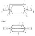
本実施形態の接着性細胞用培養容器は、例えば図1に示されるような、軟包材からなる袋状の接着性細胞用培養容器であって、第一容器壁11及び第二容器壁12を有する容器本体部1と、1つ以上の注入出用ポート2とを備え、容器本体部1が、第一容器壁11と第二容器壁12の間に中間培養壁13を有し、第一容器壁11と中間培養壁13の間及び第二容器壁12と中間培養壁13の間にそれぞれ培養室が備えられ、各培養室を連通する流路14を備えたことを特徴とする。Hereinafter, embodiments of the culture container for adhesive cells and the method for producing a culture container for adhesive cells of the present invention will be described in detail with reference to the drawings. However, the present invention is not limited to the specific contents of the following embodiments.
The adhesive cell culture container of the present embodiment is, for example, as shown in FIG. 1, a bag-shaped adhesive cell culture container made of a soft packaging material, and the
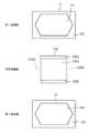
図2に示すように、第一容器壁11としては、矩形状のフィルムを用いることができ、フィルムの一方の表面が接着性細胞用培養容器の外側表面を構成し、他方の表面が接着性細胞用培養容器の内側の表面を構成する。また、この内側の表面は、接着性細胞を接着して培養する領域(培養面)である培養部111と、培養部111の周囲においてフィルムをヒートシール(熱溶着)させる領域であるシール部112とからなる。
また、第二容器壁12としても、矩形状のフィルムを用いることができ、フィルムの一方の表面が接着性細胞用培養容器の外側表面を構成し、他方の表面が接着性細胞用培養容器の内側の表面を構成する。また、この内側の表面は、第一容器壁11と同様に、接着性細胞を接着して培養する領域である培養部121と、培養部121の周囲においてフィルムをヒートシールさせる領域であるシール部122とからなる。As shown in FIG. 2, a rectangular film can be used as the
Further, as the
中間培養壁13は、培養面積を増加させるために設けられた中間層であり、略矩形状のフィルムを用いることができ、第一容器壁11と第二容器壁12との間に挟み込まれて、接着性細胞用培養容器内においてフィルムの両方の表面の一部が培養部として構成される。
すなわち、中間培養壁13の両方の表面が、接着性細胞を接着して培養する領域である培養部131と、培養部131の周囲においてフィルムをヒートシールさせる領域であるシール部132とからなる。The
That is, both surfaces of the
また、中間培養壁13における培養部131は、第一容器壁11の培養部111及び第二容器壁12の培養部121に対応する領域の一部に切り欠き(又は、中間培養壁を貫通する穴)が形成されており、これが、第一容器壁11と中間培養壁13の間に形成される培養室と、第二容器壁12と中間培養壁13の間に形成される培養室を連通する流路14を構成する。 Further, the
接着性細胞用培養容器をこのような構成にすれば、接着性細胞用培養容器内における培養部として、培養部111、培養部121、及び2つの培養部131の合計4つの表面を用いることができるため、中間培養壁13を備えていない培養容器を用いて両面培養する場合に比較して、培養面積を約2倍にすることができる。
また、本実施形態の接着性細胞用培養容器は、軟包材からなる袋状のものであるため、培地や剥離液を容器内に注入する量に応じて、容器内の容量をコントロールすることができる。このため、培地や剥離液を必要以上に消費させることがない。
さらに、剥離液を作用させた後、接着性細胞用培養容器の外部から力を加えたり、培養部同士を接触させたりすることで、容易に細胞の剥離回収を行うことが可能となる。If the culture container for adhesive cells has such a configuration, a total of four surfaces of the
Further, since the culture container for adhesive cells of the present embodiment is in the shape of a bag made of a soft packaging material, the volume in the container should be controlled according to the amount of the medium or the stripping solution injected into the container. Can be done. Therefore, the medium and the stripping solution are not consumed more than necessary.
Further, after the exfoliating liquid is allowed to act, the cells can be easily exfoliated and recovered by applying a force from the outside of the culture vessel for adhesive cells or by bringing the culture portions into contact with each other.
本実施形態の接着性細胞用培養容器における第一容器壁11、第二容器壁12、及び中間培養壁13を構成するフィルムの材料としては、ポリエチレンやポリプロピレンなどのポリオレフィン系樹脂などを好適に用いることができる。例えば、ポリエチレン、エチレンとα−オレフィンの共重合体、エチレンと酢酸ビニルの共重合体、エチレンとアクリル酸やメタクリル酸共重合体と金属イオンを用いたアイオノマー等を挙げることができる。また、ポリオレフィン、スチレン系エラストマー、ポリエステル系熱可塑性エラストマー、シリコーン系熱可塑性エラストマー、シリコーン樹脂等を用いることもできる。さらに、シリコーンゴム、軟質塩化ビニル樹脂、ポリブタジエン樹脂、エチレン−酢酸ビニル共重合体、塩素化ポリエチレン樹脂、ポリウレタン系熱可塑性エラストマー、ポリエステル系熱可塑性エラストマー、シリコーン系熱可塑性エラストマー、スチレン系エラストマー、例えば、SBS(スチレン・ブタジエン・スチレン)、SIS(スチレン・イソプレン・スチレン)、SEBS(スチレン・エチレン・ブチレン・スチレン)、SEPS(スチレン・エチレン・プロピレン・スチレン)、ポリオレフィン樹脂、フッ素系樹脂等を用いてもよい。 As the material of the film constituting the
ポート2は、培地や剥離液を接着性細胞用培養容器に注入出する(注入又は排出する)ためのものであり、図1において、接着性細胞用培養容器に2個備えられているが、接着性細胞用培養容器に備えるポートの個数は2個に限定されず、1個であっても良く、3個以上であってもよい。ポート2にはチューブ3が接続されている。チューブ3は、図示しないが、培地供給容器、細胞回収容器、酵素供給容器、廃棄容器等に適宜接続され得る。 The
ポート2の材料としては、例えば、ポリエチレン、ポリプロピレン、塩化ビニル、ポリスチレン系エラストマー、FEPなどの熱可塑性樹脂等を用いることができる。
また、チューブ3の材料としては、例えば、シリコーン樹脂、軟質塩化ビニル樹脂、ポリブタジエン樹脂、エチレン−酢酸ビニル共重合体、ポリウレタン系熱可塑性エラストマー、ポリエステル系熱可塑性エラストマー、シリコーン系熱可塑性エラストマー、スチレン系エラストマー、例えば、SBS(スチレン・ブタジエン・スチレン)、SIS(スチレン・イソプレン・スチレン)、SEBS(スチレン・エチレン・ブチレン・スチレン)、SEPS(スチレン・エチレン・プロピレン・スチレン)、ポリオレフィン樹脂、フッ素系樹脂等を用いることができる。As the material of the
The material of the
図2において、第一容器壁11、第二容器壁12、及び中間培養壁13として、矩形状又は略矩形状のフィルムが用いられているが、これに限定されず、円形や楕円形、多角形などその他の形状のフィルムやシートなどを用いることができる。また、培養部111の形状は六角形状としてあるが、これに限定されず、矩形状や円形や楕円形等であってよい。 In FIG. 2, a rectangular or substantially rectangular film is used as the
また、中間培養壁13に形成される流路14は、図2において、培養部121の両端に略三角形状に形成されているが、これに限定されず、例えば図3の中間培養壁13aにおいて示される流路14aのように略長方形状などとすることもできる。
さらに、図4に示されるように、第一容器壁11及び第二容器壁12よりも短いフィルムを中間培養壁13bとして用い、これを第一容器壁11と第二容器壁12に挟み込んでヒートシールすることで、培養部131bの両側のポート近辺に、流路14bを形成させることも可能である。Further, the
Further, as shown in FIG. 4, a film shorter than the
なお、図1〜図4では、流路14(14a、14b)を接着性細胞用培養容器内において、2個備えているが、これに限定されず、いずれか1個のみを備えた構成とすることもでき、3個以上を備えた構成とすることもできる。また、流路14の位置は、これらに限定されず、流路14をその他の位置に配置することもできる。 In addition, in FIGS. 1 to 4, two flow paths 14 (14a, 14b) are provided in the culture vessel for adhesive cells, but the present invention is not limited to this, and only one of them is provided. It can also be configured to include three or more. Further, the position of the
また、本実施形態の接着性細胞用培養容器は、中間培養壁が、第一容器壁と第二容器壁の間に複数備えられ、中間培養壁の間に培養室が備えられ、各培養室を連通する流路を備えたものとすることも好ましい。
例えば、図5(A)に示すように、第一容器壁11と第二容器壁12の間に中間培養壁13が2層備えられ、第一容器壁11と中間培養壁13の間と、二層の中間培養壁13の間と、第二容器壁12と中間培養壁13の間にそれぞれ培養室が備えられ、これらの培養室を連通する流路14を備えたものとすることも好ましい。Further, in the culture container for adhesive cells of the present embodiment, a plurality of intermediate culture walls are provided between the first container wall and the second container wall, and a culture chamber is provided between the intermediate culture walls, and each culture chamber is provided. It is also preferable to provide a flow path for communicating the above.
For example, as shown in FIG. 5A, two layers of the
接着性細胞用培養容器をこのような構成にすれば、接着性細胞用培養容器内における培養部として、培養部111、培養部121、及び4つの培養部131の合計6つの表面を用いることができるため、中間培養壁13を備えていない培養容器を用いて両面培養する場合に比較して、培養面積を約3倍にすることができる。
また、接着性細胞用培養容器をこのような構成にしても、当該容器は軟包材からなる袋状のものであるため、培地や剥離液を容器内に注入する量に応じて、容器内の容量をコントロールすることができ、培地や剥離液を必要以上に消費させることがなく、容易に細胞の剥離回収を行うことが可能になっている。If the culture container for adhesive cells is configured in this way, a total of six surfaces of the
Further, even if the culture container for adhesive cells has such a configuration, since the container is in the shape of a bag made of a soft packaging material, the inside of the container depends on the amount of the medium or the stripping solution injected into the container. It is possible to control the volume of the cells, and it is possible to easily exfoliate and collect the cells without consuming the medium and the exfoliating solution more than necessary.
また、図5(B)に示すように、第一容器壁11と第二容器壁12の間に中間培養壁13が3層備えられ、第一容器壁11と中間培養壁13の間と、三層の中間培養壁13の間と、第二容器壁12と中間培養壁13の間にそれぞれ培養室が備えられ、これらの培養室を連通する流路14を備えたものとすることも好ましい。 Further, as shown in FIG. 5B, three layers of the
接着性細胞用培養容器をこのような構成にすれば、接着性細胞用培養容器内における培養部として、培養部111、培養部121、及び6つの培養部131の合計8つの表面を用いることができるため、中間培養壁13を備えていない培養容器を用いて両面培養する場合に比較して、培養面積を約4倍にすることができる。
また、本実施形態の接着性細胞用培養容器において、第一容器壁11と第二容器壁12の間に中間培養壁13を4層以上備えることもでき、それに応じて培養面積を増加させることで、培養効率をさらに向上させることも可能である。If the culture container for adhesive cells is configured in this way, a total of eight surfaces of the
Further, in the culture container for adhesive cells of the present embodiment, four or more layers of the
なお、図5(A)及び図5(B)の接着性細胞用培養容器は、図1に比較してポート2の厚みがやや大きくなっているが、これは描画上の理由によるものであり、これらのポート2の厚みは同一であってよい。 In the culture vessels for adhesive cells shown in FIGS. 5 (A) and 5 (B), the thickness of the
本実施形態の接着性細胞用培養容器において、培養部の一部を、接着性細胞を培養する培養面として使用しないようにすることもできる。これは、培養部に対して表面処理を行うか否かにより変更できる。なお、表面処理については後述する。 In the culture container for adhesive cells of the present embodiment, it is also possible not to use a part of the culture part as a culture surface for culturing the adhesive cells. This can be changed depending on whether or not the surface treatment is applied to the cultured portion. The surface treatment will be described later.
また、本実施形態の接着性細胞用培養容器は、図1に示すように、第1容器壁11及び第2容器壁12が、培養室の周縁領域において、外側向きに張り出した膨出形状を有することが好ましい。
第1容器壁11及び第2容器壁12をこのような構成にすることによって、第一容器壁11と中間培養壁13の間、及び、第二容器壁12と中間培養壁13の間において、培養室をより安定して形成させることができる。
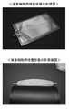
図6に実際に製造した本実施形態の接着性細胞用培養容器の写真を示す。同図において、接着性細胞用培養容器の培養室の周縁領域に外側向きに張り出した膨出形状が形成されている。Further, as shown in FIG. 1, the culture container for adhesive cells of the present embodiment has a bulging shape in which the
By forming the
FIG. 6 shows a photograph of the actually manufactured culture container for adhesive cells of the present embodiment. In the figure, a bulging shape protruding outward is formed in the peripheral region of the culture chamber of the culture vessel for adhesive cells.
また、図5に示すように、中間培養壁13が、培養室の周縁領域において、外側向きに張り出した膨出形状を有することも好ましい。
中間培養壁13をこのような構成にすることによって、第一容器壁11と中間培養壁13の間、第二容器壁12と中間培養壁13の間、及び複数の中間培養壁13の間において、培養室をより安定して形成させることが可能となる。Further, as shown in FIG. 5, it is also preferable that the
By making the
また、本実施形態の接着性細胞用培養容器は、第一容器壁11、第二容器壁12、及び中間培養壁13の厚みが1mm以下であることが好ましい。
本実施形態の接着性細胞用培養容器をこのような構成にすれば、剥離液を用いた後、培養容器の外側から叩くことで、接着性細胞を容易に剥離することができる。また、第一容器壁11、第二容器壁12の厚みを1mm以下とすることで、接着性細胞用培養容器内のガス透過性を高めることもできる。Further, in the culture container for adhesive cells of the present embodiment, the thickness of the
If the culture vessel for adhesive cells of the present embodiment has such a configuration, the adhesive cells can be easily detached by tapping from the outside of the culture vessel after using the exfoliating solution. Further, by setting the thickness of the
また、本実施形態の接着性細胞用培養容器は、少なくとも第一容器壁11の培養室側表面又は中間培養壁13の第一容器壁側表面の全部又は一部、及び、少なくとも第二容器壁12の培養室側表面又は中間培養壁13の第二容器壁側表面の全部又は一部が、接着性細胞を表面に接着可能にするための表面処理が施されてなることが好ましい。
本実施形態の接着性細胞用培養容器をこのような構成にすることにより、接着性細胞用培養容器内において、培養部を好適に形成させることができる。
表面処理としては、例えばコロナ処理やエキシマ処理などを行うことができる。Further, the culture container for adhesive cells of the present embodiment includes at least all or a part of the culture chamber side surface of the
By forming the culture container for adhesive cells of the present embodiment in such a configuration, a culture portion can be suitably formed in the culture container for adhesive cells.
As the surface treatment, for example, a corona treatment or an excimer treatment can be performed.
また、本実施形態の接着性細胞用培養容器は、第一容器壁11、第二容器壁12、及び中間培養壁13の培養部の各表面における表面処理が施された領域に、山状部と谷状部からなる複数の溝が備えられた構成とすることが好ましい。
さらに、当該溝は、溝が延びる方向に垂直な断面が略V字形状であり(以下、このような形状の溝をV字状の溝と称する場合がある。)、溝における略V字形状の側面の傾斜角(以下、V字角度と称する場合がある。)が80度以下であることが好ましい。Further, in the culture container for adhesive cells of the present embodiment, a chevron-shaped portion is formed on each surface of the culture part of the
Further, the groove has a substantially V-shaped cross section perpendicular to the extending direction of the groove (hereinafter, the groove having such a shape may be referred to as a V-shaped groove), and the groove has a substantially V-shape. The inclination angle of the side surface of the above (hereinafter, may be referred to as a V-shaped angle) is preferably 80 degrees or less.
ここで、溝のV字角度が60度の場合、当該溝の表面積は、当該溝がない場合の対応する領域の表面積に対して2倍となる。同様に、V字角度が65度の場合、当該溝の表面積は2.37倍となり、V字角度が70度の場合、当該溝の表面積は2.92倍となり、V字角度が75度の場合、当該溝の表面積は3.86倍となり、V字角度が80度の場合、当該溝の表面積は5.67倍となる。 Here, when the V-shaped angle of the groove is 60 degrees, the surface area of the groove is twice as large as the surface area of the corresponding region when the groove is not present. Similarly, when the V-shaped angle is 65 degrees, the surface area of the groove is 2.37 times, and when the V-shaped angle is 70 degrees, the surface area of the groove is 2.92 times, and the V-shaped angle is 75 degrees. In this case, the surface area of the groove is 3.86 times, and when the V-shaped angle is 80 degrees, the surface area of the groove is 5.67 times.
したがって、培養面積の観点からは、V字角度は大きいほど好ましい。一方、V字角度は大きいほど、加工型の先端部にチッピングが生じたり、加工物の先端が変形したりするなど、加工性能が低下する。V字角度が83度の場合、当該溝の表面積は8.21倍となるが、このV字角度では、加工型を製作することが難しく、V字角度が80度の加工型を製作して、これを用いて加工物を作成することが概ね限界である。 Therefore, from the viewpoint of the culture area, the larger the V-shaped angle is, the more preferable. On the other hand, the larger the V-shaped angle, the lower the machining performance, such as chipping at the tip of the machining die and deformation of the tip of the workpiece. When the V-shaped angle is 83 degrees, the surface area of the groove is 8.21 times, but it is difficult to manufacture a processing mold with this V-shaped angle, and a processing mold with a V-shaped angle of 80 degrees is manufactured. , It is generally the limit to make a work piece using this.
次に、このようなV字状の溝の構成について、図7を参照して説明する。
同図において、角度θは、V字状の溝の傾斜角(V字角度)であり、V字状の溝の側面と、第一容器壁11、第二容器壁12、及び中間培養壁13を構成する器材(フィルム)の他方の表面(器材の下面)に平行で溝の最下点を通る面とのなす角を示している。Next, the configuration of such a V-shaped groove will be described with reference to FIG. 7.
In the figure, the angle θ is the inclination angle (V-shaped angle) of the V-shaped groove, and the side surface of the V-shaped groove, the
距離aは、山状部の頂端部から溝の中央までの水平距離(=溝の最下点から山状部の中央までの水平距離)である。山状部の頂端部間の距離(ピッチ)は2aとなる。
距離bは、溝の深さであり、山状部の頂端部から溝の最下点を通る平面までの垂直距離を示している。すなわち、溝の深さは、b=tanθ×aにより算出される。
距離cは、器材の底部の厚みであり、器材の厚みから溝の深さを引いた距離を示している。
距離hは、器材の厚みであり、h=b+c=tanθ×a+cにより算出される。
距離Hは、器材の製造に用いられる元の材料の厚みであり、H=b/2+c=tanθ×a/2+cにより算出される。The distance a is a horizontal distance from the top end of the mountain-shaped portion to the center of the groove (= horizontal distance from the lowest point of the groove to the center of the mountain-shaped portion). The distance (pitch) between the apex portions of the mountain-shaped portion is 2a.
The distance b is the depth of the groove, and indicates the vertical distance from the top end of the mountain-shaped portion to the plane passing through the lowest point of the groove. That is, the groove depth is calculated by b = tan θ × a.
The distance c is the thickness of the bottom of the equipment, and indicates the distance obtained by subtracting the depth of the groove from the thickness of the equipment.
The distance h is the thickness of the equipment and is calculated by h = b + c = tan θ × a + c.
The distance H is the thickness of the original material used for manufacturing the equipment, and is calculated by H = b / 2 + c = tan θ × a / 2 + c.
なお、器材は、被加工物に成形型を載せて加熱転写を行うことにより好適に製造することができる。このとき、器材の溝に対応する成形型の凸部が、材料に押しつけられることによって溝が形成されると共に、溝の部分に存在した材料が押しのけられて山状部が形成されるため、元の材料の厚みよりも器材の厚みの方が大きくなる。また、V字状の溝は図7の紙面に対して上下方向に延びる構成であり、同図において、a×(H−c)=a×b/2の関係が成り立つ。このため、元の材料の厚みHは、上記の式により算出される。 The equipment can be suitably manufactured by placing a molding die on the work piece and performing thermal transfer. At this time, the convex portion of the molding die corresponding to the groove of the equipment is pressed against the material to form a groove, and the material existing in the groove portion is pushed away to form a mountain-shaped portion. The thickness of the equipment is larger than the thickness of the material of. Further, the V-shaped groove has a structure extending in the vertical direction with respect to the paper surface of FIG. 7, and the relationship of a × (Hc) = a × b / 2 is established in the figure. Therefore, the thickness H of the original material is calculated by the above formula.
また、本実施形態の接着性細胞用培養容器は、複数の溝が直線状に並行して備えられ、山状部の頂端部が直線状であることが好ましい。
具体的には、図8の上の写真(V字状の溝)に示されるように、ライン形状にV字状の溝を備える構成とすることが好ましい。また、溝の断面を、図8の下の写真(V字状の溝が延びる方向に垂直な断面)に示す。
本実施形態の接着性細胞用培養容器をこのような構成にすれば、接着性細胞をこのライン形状の溝に沿って増殖させることができるため、培養面積を有効に増やすことが可能である。Further, it is preferable that the culture vessel for adhesive cells of the present embodiment is provided with a plurality of grooves linearly in parallel, and the apex portion of the mountain-shaped portion is linear.
Specifically, as shown in the upper photograph (V-shaped groove) of FIG. 8, it is preferable that the line shape is provided with the V-shaped groove. The cross section of the groove is shown in the lower photograph of FIG. 8 (cross section perpendicular to the direction in which the V-shaped groove extends).
If the culture vessel for adhesive cells of the present embodiment has such a configuration, the adhesive cells can be grown along the groove of this line shape, so that the culture area can be effectively increased.
また、本実施形態の接着性細胞用培養容器は、複数の溝が、溝の延びる方向が互いに対面する表面において互いに平行でなく備えられた構成とすることが好ましい。
本実施形態の接着性細胞用培養容器をこのような構成にすれば、互いに対面する表面に備えられた溝が延びる方向をずらすことができ、それらの溝が重なり合って接着した細胞が剥離されることを防止することが可能である。Further, it is preferable that the culture vessel for adhesive cells of the present embodiment is provided with a plurality of grooves that are not parallel to each other on the surfaces in which the extending directions of the grooves face each other.
When the culture container for adhesive cells of the present embodiment has such a configuration, the directions in which the grooves provided on the surfaces facing each other extend can be shifted, and the grooves overlap and the adhered cells are peeled off. It is possible to prevent this.
また、本実施形態の接着性細胞用培養容器は、例えば図1に示すように、複数のポート2が、培養室の周縁領域において、対向して備えられた構成とすることが好ましい。
本実施形態の接着性細胞用培養容器をこのような構成にすれば、接着性細胞用培養容器への培地や剥離液の注入及び排出を効率的に行うことが可能である。Further, the culture vessel for adhesive cells of the present embodiment preferably has a configuration in which a plurality of
If the culture vessel for adhesive cells of the present embodiment has such a configuration, it is possible to efficiently inject and discharge the medium and the stripping solution into the culture vessel for adhesive cells.
本実施形態の接着性細胞用培養容器の製造方法は、軟包材からなる袋状の接着性細胞用培養容器の製造方法であって、3枚以上の軟包材フィルムに山状部と谷状部からなる複数の溝を形成し、軟包材フィルムにおける溝が形成された面を当該培養容器内に配置し、1つ以上の注入出用ポートを軟包材フィルムに挟んで軟包材フィルムの周縁部をヒートシールし、真空成形、圧空成形、又は真空圧空成形により、軟包材フィルム間に培養室を形成すると共に、各培養室を連通する流路を備えることを特徴とする。 The method for producing the culture container for adhesive cells of the present embodiment is a method for producing a bag-shaped culture container for adhesive cells made of a soft packaging material, and has a chevron and a valley on three or more soft packaging film. A plurality of grooves composed of shaped portions are formed, the grooved surface of the soft packaging material film is arranged in the culture vessel, and one or more injection / delivery ports are sandwiched between the soft packaging material films. The peripheral portion of the film is heat-sealed, and a culture chamber is formed between the soft packaging material films by vacuum molding, pressure air forming, or vacuum pressure air forming, and a flow path communicating with each culture chamber is provided.
具体的には、例えば、第一容器壁11、第二容器壁12、及び中間培養壁13における各培養部に表面処理を施した後、当該培養部に複数のV字状の溝を直線状に形成する。
次に、中間培養壁13に、培養室間の流路を形成するための切り欠き(又は穴)を形成する。なお、図4を参照して上述したように、第一容器壁11及び第二容器壁12よりも短い中間培養壁13(13b)を用いる場合は、当該切り欠き(又は穴)を形成する必要がない。Specifically, for example, after surface-treating each culture portion in the
Next, a notch (or hole) for forming a flow path between the culture chambers is formed in the
さらに、第一容器壁11と第二容器壁12の間に、中間培養壁13を挟み込むと共に、ポート2を挟み込んで、周縁のシール部をヒートシールすることにより、接着性細胞用培養容器を製袋する。
このとき、第一容器壁11と中間培養壁13の向かい合う培養部の少なくとも一方に、複数のV字状の溝が形成された培養部を配置する。また、第二容器壁12と中間培養壁13の向かい合う培養部の少なくとも一方に、複数のV字状の溝が形成された培養部を配置する。Further, the
At this time, a culture section having a plurality of V-shaped grooves is arranged on at least one of the culture sections facing the
そして、真空成形、圧空成形、又は真空圧空成形を行って第一容器壁11と第二容器壁12を膨出形状を有するように成形する。
このとき、接着性細胞用培養容器内の各培養室にエアーを均一に流入させることができ、各培養室を連通する流路14を備えた本実施形態の接着性細胞用培養容器を好適に製造することができる。
このような本実施形態の接着性細胞用培養容器の製造方法によれば、比較的簡単に4面以上の培養部を備えた接着性細胞用培養容器を好適に製造することが可能である。Then, vacuum forming, compressed air forming, or vacuum forming is performed to form the
At this time, the culture vessel for adhesive cells of the present embodiment, which can uniformly flow air into each culture chamber in the culture vessel for adhesive cells and has a
According to the method for producing an adhesive cell culture vessel of the present embodiment, it is possible to suitably produce an adhesive cell culture vessel having four or more surfaces of culture portions relatively easily.
また、本実施形態の袋状の接着性細胞用培養容器の製造方法は、軟包材からなる袋状の接着性細胞用培養容器の製造方法であって、2枚の軟包材フィルムの周縁領域に外側向きに張り出した膨出形状を真空成形、圧空成形、又は真空圧空成形により成形して第一容器壁及び第二容器壁とし、当該接着性細胞用培養容器において中間培養壁を複数備える場合、中央に配置される中間培養壁以外に用いられる軟包材フィルムの周縁領域に外側向きに張り出した膨出形状を真空成形、圧空成形、又は真空圧空成形により成形して、それぞれ中間培養壁とし、第一容器壁と第二容器壁の間に、1つ以上の注入出用ポートと中間培養壁を挟んで軟包材フィルムの周縁部をヒートシールし、軟包材フィルム間に培養室を形成すると共に、各培養室を連通する流路を備える方法とすることも好ましい。 Further, the method for producing a bag-shaped culture container for adhesive cells according to the present embodiment is a method for producing a bag-shaped culture container for adhesive cells made of a soft packaging material, and is a peripheral edge of two flexible packaging material films. The bulging shape protruding outward from the region is formed by vacuum molding, pressure air forming, or vacuum pressure air forming to form a first container wall and a second container wall, and the adhesive cell culture container is provided with a plurality of intermediate culture walls. In the case, the bulging shape protruding outward from the peripheral region of the flexible packaging material film used other than the intermediate culture wall arranged in the center is formed by vacuum molding, pressure air forming, or vacuum pressure air forming, and each intermediate culture wall is formed. The peripheral edge of the soft packaging material film is heat-sealed with one or more injection / discharge ports and an intermediate culture wall sandwiched between the first container wall and the second container wall, and the culture chamber is sandwiched between the soft packaging material films. It is also preferable to use a method in which a flow path is provided to communicate with each culture chamber.
具体的には、例えば、接着性細胞用培養容器の製袋を行うのに先立って、第一容器壁11、第二容器壁12、及び中間培養壁13(中央の層を除く)の各軟包材フィルムに対して、真空成形、圧空成形、又は真空圧空成形により、培養室の周縁となる領域に外側向きに張り出した膨出形状を成形する。 Specifically, for example, prior to making a bag of the culture container for adhesive cells, each soft of the
なお、第一容器壁11、第二容器壁12、及び中間培養壁13における各培養部に表面処理を施した後、当該培養部に複数のV字状の溝を直線状に形成しておくことが好ましい。また、中間培養壁13には、培養室間の流路を形成するための切り欠き(又は穴)を形成する。なお、図4を参照して上述したように、第一容器壁11及び第二容器壁12よりも短い中間培養壁13(13b)を用いる場合は、当該切り欠き(又は穴)を形成する必要がない。 After surface treatment is applied to each of the culture portions in the
接着性細胞用培養容器において、中間培養壁13が複数備えられる場合や、向かい合う培養部の両方が平面である場合、製袋後に真空成形、圧空成形、又は真空圧空成形を行うと、接着性細胞用培養容器内の各培養室にエアーを均一に流入できないことがある。
そこで、これらの場合には、第一容器壁11、第二容器壁12、及び中間培養壁13について膨出形状を成形した後、第一容器壁11と第二容器壁12の間に、中間培養壁13とポート2を挟み込んで周縁のシール部をヒートシールすることにより、各培養室を連通する流路を備えた接着性細胞用培養容器を製袋することが好ましい。In the culture vessel for adhesive cells, when a plurality of
Therefore, in these cases, after forming a bulging shape for the
このような本実施形態の接着性細胞用培養容器の製造方法によれば、第一容器壁11、第二容器壁12、及び中間培養壁13の向かい合う培養部の両方が平面である場合や、中間培養壁13を複数備える場合であっても、接着性細胞用培養容器を好適に製造することが可能となる。 According to the method for producing an adhesive cell culture vessel of the present embodiment, when both the
以上説明したように、本実施形態の接着性細胞用培養容器、及び接着性細胞用培養容器の製造方法によれば、軟包材からなる袋状の培養容器内において、4面以上の培養部が備えられるため、培養部の表面積を大きくでき、かつ、培地や剥離液を必要以上に消費させることがなく、容易に細胞の剥離回収を行うことができる。
すなわち、培地や剥離液を容器内に注入する量に応じて、容器内の容量をコントロールすることができため、培地や剥離液を必要以上に消費させることがなく、無駄な消費を削減することが可能となる。また、剥離液を作用させた後、接着性細胞用培養容器の外部から力を加えたり、培養部同士を接触させたりすることで、容易に細胞を回収することが可能となる。
さらに、培養部に山状部と谷状部からなる複数の溝を備えることにより、培養部の表面積を一層大きくすることも可能となっている。As described above, according to the method for producing the culture container for adhesive cells and the culture container for adhesive cells of the present embodiment, the culture unit having four or more surfaces in the bag-shaped culture container made of the soft packaging material. Therefore, the surface area of the culture section can be increased, and the cells can be easily exfoliated and recovered without consuming the medium or the exfoliating solution more than necessary.
That is, since the volume in the container can be controlled according to the amount of the medium or stripping solution injected into the container, the medium or stripping solution is not consumed more than necessary, and wasteful consumption is reduced. Is possible. Further, after the stripping solution is allowed to act, the cells can be easily collected by applying a force from the outside of the culture container for adhesive cells or by bringing the culture parts into contact with each other.
Further, the surface area of the culture portion can be further increased by providing the culture portion with a plurality of grooves composed of a mountain-shaped portion and a valley-shaped portion.
本発明は、以上の実施形態及び実施例に限定されるものではなく、本発明の範囲内において、種々の変更実施が可能であることは言うまでもない。例えば、接着性細胞用培養容器の培養部における溝を直線状ではなく曲線状に形成するなど適宜変更することが可能である。また、培養部に表面処理を行わず、浮遊性細胞の培養に適用した細胞培養容器とすることも可能である。 It goes without saying that the present invention is not limited to the above embodiments and examples, and various modifications can be made within the scope of the present invention. For example, it is possible to appropriately change the groove in the culture portion of the culture container for adhesive cells, such as forming a curved shape instead of a straight line. It is also possible to use a cell culture container applied to the culture of floating cells without surface-treating the culture unit.
本発明は、接着性細胞を効率的に大量に作成する場合などに、好適に利用することが可能である。 The present invention can be suitably used when efficiently producing a large amount of adhesive cells.
1 容器本体部
11 第一容器壁
111 培養部
112 シール部
12 第二容器壁
121 培養部
122 シール部
13,13a,13b 中間培養壁
131,131a,131b 培養部
132,132a,132b シール部
14,14a 流路
2 ポート
3 チューブ1
Claims (15)
Translated fromJapanese前記容器本体部が、前記第一容器壁と前記第二容器壁の間に中間培養壁を有し、
前記第一容器壁と前記中間培養壁の間及び前記第二容器壁と前記中間培養壁の間にそれぞれ培養室が備えられ、前記各培養室を連通する流路を備えた
ことを特徴とする接着性細胞用培養容器。A bag-shaped culture container for adhesive cells made of a soft packaging material, which is provided with a container body having a first container wall and a second container wall, and one or more injection / discharge ports.
The container body has an intermediate culture wall between the first container wall and the second container wall.
A culture chamber is provided between the first container wall and the intermediate culture wall and between the second container wall and the intermediate culture wall, and a flow path communicating with each of the culture chambers is provided. Culture vessel for adherent cells.
前記容器本体部が、前記第一容器壁と前記第二容器壁の間に中間培養壁を有し、
前記第一容器壁と前記中間培養壁の間及び前記第二容器壁と前記中間培養壁の間にそれぞれ培養室が備えられ、前記各培養室を連通する流路を備えた
ことを特徴とする細胞培養容器。A bag-shaped cell culture container made of a soft packaging material, which is provided with a container body having a first container wall and a second container wall, and one or more injection / discharge ports.
The container body has an intermediate culture wall between the first container wall and the second container wall.
A culture chamber is provided between the first container wall and the intermediate culture wall and between the second container wall and the intermediate culture wall, and a flow path communicating with each of the culture chambers is provided. Cell culture container.
3枚以上の軟包材フィルムに山状部と谷状部からなる複数の溝を形成し、
前記軟包材フィルムにおける前記溝が形成された面を当該培養容器内に配置し、
1つ以上の注入出用ポートを前記軟包材フィルムに挟んで前記軟包材フィルムの周縁部をヒートシールし、
真空成形、圧空成形、又は真空圧空成形により、前記軟包材フィルム間に培養室を形成すると共に、前記各培養室を連通する流路を備える
ことを特徴とする接着性細胞用培養容器の製造方法。A method for producing a bag-shaped culture container for adhesive cells made of a soft packaging material.
Multiple grooves consisting of mountain-shaped parts and valley-shaped parts are formed on three or more soft packaging material films.
The grooved surface of the flexible packaging film is placed in the culture vessel.
One or more injection / delivery ports are sandwiched between the flexible packaging material films, and the peripheral edge portion of the flexible packaging material film is heat-sealed.
Manufacture of a culture vessel for adhesive cells, which comprises forming a culture chamber between the soft packaging material films by vacuum forming, vacuum forming, or vacuum forming, and providing a flow path communicating with each of the culture chambers. Method.
2枚の軟包材フィルムの周縁領域に外側向きに張り出した膨出形状を真空成形、圧空成形、又は真空圧空成形により成形して第一容器壁及び第二容器壁とし、
当該接着性細胞用培養容器において中間培養壁を複数備える場合、中央に配置される中間培養壁以外に用いられる軟包材フィルムの周縁領域に外側向きに張り出した膨出形状を真空成形、圧空成形、又は真空圧空成形により成形して、それぞれ中間培養壁とし、
前記第一容器壁と前記第二容器壁の間に、1つ以上の注入出用ポートと前記中間培養壁を挟んで前記軟包材フィルムの周縁部をヒートシールし、前記軟包材フィルム間に培養室を形成すると共に、前記各培養室を連通する流路を備える
ことを特徴とする接着性細胞用培養容器の製造方法。
A method for producing a bag-shaped culture container for adhesive cells made of a soft packaging material.
The bulging shape protruding outward from the peripheral region of the two flexible packaging material films is formed by vacuum forming, compressed air forming, or vacuum forming to form the first container wall and the second container wall.
When a plurality of intermediate culture walls are provided in the culture container for adhesive cells, a bulging shape protruding outward from the peripheral region of the soft packaging material film used other than the intermediate culture wall arranged in the center is vacuum formed or pneumatically formed. , Or by vacuum forming to make intermediate culture walls, respectively.
The peripheral edge of the soft packaging material film is heat-sealed with one or more injection / discharging ports and the intermediate culture wall sandwiched between the first container wall and the second container wall, and between the soft packaging material films. A method for producing a culture vessel for adhesive cells, which comprises forming a culture chamber in the same manner and providing a flow path communicating with each of the culture chambers.
Priority Applications (5)
| Application Number | Priority Date | Filing Date | Title |
|---|---|---|---|
| JP2019237046AJP2021103973A (en) | 2019-12-26 | 2019-12-26 | Culture vessel for adhesive cell, and method for manufacturing culture vessel for adhesive cell |
| PCT/JP2020/047599WO2021132121A1 (en) | 2019-12-26 | 2020-12-21 | Adherent cell culture vessel, and method for producing adherent cell culture vessel |
| EP20908148.8AEP4063478A4 (en) | 2019-12-26 | 2020-12-21 | Adherent cell culture vessel, and method for producing adherent cell culture vessel |
| CN202080089202.1ACN114867838A (en) | 2019-12-26 | 2020-12-21 | Culture container for adherent cells and method for producing culture container for adherent cells |
| US17/845,650US20220315879A1 (en) | 2019-12-26 | 2022-06-21 | Adherent cell culture vessel, and method for producing adherent cell culture vessel |
Applications Claiming Priority (1)
| Application Number | Priority Date | Filing Date | Title |
|---|---|---|---|
| JP2019237046AJP2021103973A (en) | 2019-12-26 | 2019-12-26 | Culture vessel for adhesive cell, and method for manufacturing culture vessel for adhesive cell |
Publications (1)
| Publication Number | Publication Date |
|---|---|
| JP2021103973Atrue JP2021103973A (en) | 2021-07-26 |
Family
ID=76576102
Family Applications (1)
| Application Number | Title | Priority Date | Filing Date |
|---|---|---|---|
| JP2019237046APendingJP2021103973A (en) | 2019-12-26 | 2019-12-26 | Culture vessel for adhesive cell, and method for manufacturing culture vessel for adhesive cell |
Country Status (5)
| Country | Link |
|---|---|
| US (1) | US20220315879A1 (en) |
| EP (1) | EP4063478A4 (en) |
| JP (1) | JP2021103973A (en) |
| CN (1) | CN114867838A (en) |
| WO (1) | WO2021132121A1 (en) |
Families Citing this family (1)
| Publication number | Priority date | Publication date | Assignee | Title |
|---|---|---|---|---|
| JP2023016393A (en)* | 2021-07-21 | 2023-02-02 | 東洋製罐グループホールディングス株式会社 | Method for manufacturing cell culture vessel and cell culture vessel |
Citations (6)
| Publication number | Priority date | Publication date | Assignee | Title |
|---|---|---|---|---|
| JPH0638734A (en)* | 1991-12-18 | 1994-02-15 | Corning Inc | Cell culture container having interior raised part and method for cultivating cell in said container |
| EP1132460A2 (en)* | 2000-03-06 | 2001-09-12 | Sefar AG | Bioreactor and process for the growth of dentritic cells |
| JP2007500505A (en)* | 2003-07-31 | 2007-01-18 | ブルー メンブレーンス ゲーエムベーハー | Cell culture and proliferation method |
| JP2010161981A (en)* | 2009-01-16 | 2010-07-29 | Olympus Corp | Culturing container and method for culturing cell |
| WO2014148508A1 (en)* | 2013-03-22 | 2014-09-25 | 株式会社ジェイ・エム・エス | Cell culture vessel |
| WO2017183570A1 (en)* | 2016-04-18 | 2017-10-26 | 東洋製罐グループホールディングス株式会社 | Cell culture vessel and usage method therefor |
Family Cites Families (7)
| Publication number | Priority date | Publication date | Assignee | Title |
|---|---|---|---|---|
| US7560274B1 (en)* | 1999-05-28 | 2009-07-14 | Cellon S.A. | Culture chamber |
| FR2849054B1 (en)* | 2002-12-20 | 2005-06-24 | Maco Pharma Sa | THERMOFORMED CONTAINER FOR CELL CULTURE |
| WO2008104599A1 (en)* | 2007-02-28 | 2008-09-04 | Cinvention Ag | High surface cultivation system bag |
| AU2011251055B2 (en)* | 2010-05-12 | 2014-12-04 | Scinus Cell Expansion B.V. | Cell - culture - bag |
| JP6268770B2 (en)* | 2013-06-28 | 2018-01-31 | 東洋製罐グループホールディングス株式会社 | Cell detachment method |
| JP6870610B2 (en) | 2015-05-25 | 2021-05-12 | ニプロ株式会社 | Incubator |
| EP3484997A4 (en)* | 2016-07-12 | 2020-07-29 | California Institute of Technology | SUBSTRATES FOR HIGH-DENSITY CELL GROWTH AND METABOLITE EXCHANGE |
- 2019
- 2019-12-26JPJP2019237046Apatent/JP2021103973A/enactivePending
- 2020
- 2020-12-21WOPCT/JP2020/047599patent/WO2021132121A1/ennot_activeCeased
- 2020-12-21EPEP20908148.8Apatent/EP4063478A4/enactivePending
- 2020-12-21CNCN202080089202.1Apatent/CN114867838A/enactivePending
- 2022
- 2022-06-21USUS17/845,650patent/US20220315879A1/enactivePending
Patent Citations (6)
| Publication number | Priority date | Publication date | Assignee | Title |
|---|---|---|---|---|
| JPH0638734A (en)* | 1991-12-18 | 1994-02-15 | Corning Inc | Cell culture container having interior raised part and method for cultivating cell in said container |
| EP1132460A2 (en)* | 2000-03-06 | 2001-09-12 | Sefar AG | Bioreactor and process for the growth of dentritic cells |
| JP2007500505A (en)* | 2003-07-31 | 2007-01-18 | ブルー メンブレーンス ゲーエムベーハー | Cell culture and proliferation method |
| JP2010161981A (en)* | 2009-01-16 | 2010-07-29 | Olympus Corp | Culturing container and method for culturing cell |
| WO2014148508A1 (en)* | 2013-03-22 | 2014-09-25 | 株式会社ジェイ・エム・エス | Cell culture vessel |
| WO2017183570A1 (en)* | 2016-04-18 | 2017-10-26 | 東洋製罐グループホールディングス株式会社 | Cell culture vessel and usage method therefor |
Non-Patent Citations (1)
| Title |
|---|
| 生物工学, vol. 第92巻, 第9号, JPN6024013691, 2014, pages 491 - 494, ISSN: 0005304269* |
Also Published As
| Publication number | Publication date |
|---|---|
| WO2021132121A1 (en) | 2021-07-01 |
| EP4063478A4 (en) | 2023-05-24 |
| US20220315879A1 (en) | 2022-10-06 |
| CN114867838A (en) | 2022-08-05 |
| EP4063478A1 (en) | 2022-09-28 |
Similar Documents
| Publication | Publication Date | Title |
|---|---|---|
| JP6405690B2 (en) | Multi-chamber culture container and cell culture method | |
| WO2021132121A1 (en) | Adherent cell culture vessel, and method for producing adherent cell culture vessel | |
| JP7352982B2 (en) | Culture solution storage container | |
| JP2023138839A (en) | Organism manipulation device and organism manipulation method | |
| JP2016101095A (en) | Cell culture vessel, cell culture vessel filled with culture medium, and culture method of cell | |
| WO2017145870A1 (en) | Cell culture vessel and jig for fixing cell culture vessel | |
| JP2006314204A (en) | Method for exfoliating animal cells from culture vessels and method for exfoliating and collecting them | |
| JP7057878B2 (en) | Adhesive cell culture equipment, culture vessel, cell detachment method, and method for manufacturing adhesive cell culture equipment | |
| JP4706327B2 (en) | Cell culture vessel | |
| JP7661680B2 (en) | Cell culture vessel, cell culture vessel manufacturing method, and cell manufacturing method | |
| US20230134478A1 (en) | Cell culture vessel, method for producing cell culture vessel, method for producing cells, cell culture apparatus, and cell culture jig | |
| US20210238525A1 (en) | Sphere culture member, culture container, method for processing perforated member, and cleaning container | |
| JP5309658B2 (en) | Culture method and culture apparatus | |
| JP6447125B2 (en) | Cell culture vessel | |
| JP3192421U (en) | Culture vessel adapter and culture medium supply system provided with the same | |
| JP2013099260A5 (en) | ||
| WO2020090563A1 (en) | Culturing container, culturing method, and transporting method | |
| JP2022016210A (en) | Cell culture vessel, cell culture vessel manufacturing method, cell manufacturing method, and cell culture device | |
| JP2025005027A (en) | Liquid-filled culture bag, method for making liquid-filled culture bag, and method for using liquid-filled culture bag | |
| EP4375357A1 (en) | Method for manufacturing cell culture container, and cell culture container | |
| JP2009027945A (en) | Method for producing bag-like container with hydrophilized inner surface | |
| CN215350692U (en) | Exempt from to wash, be suitable for electromagnetism to snatch or plasma bag that releases | |
| CN103083747B (en) | A kind of gas liquid exchanger | |
| WO2023144933A1 (en) | Cell culture vessel | |
| WO2024247065A1 (en) | Cell culture container and cell culture method |
Legal Events
| Date | Code | Title | Description |
|---|---|---|---|
| A621 | Written request for application examination | Free format text:JAPANESE INTERMEDIATE CODE: A621 Effective date:20221128 | |
| A131 | Notification of reasons for refusal | Free format text:JAPANESE INTERMEDIATE CODE: A131 Effective date:20231010 | |
| A601 | Written request for extension of time | Free format text:JAPANESE INTERMEDIATE CODE: A601 Effective date:20231205 | |
| A521 | Request for written amendment filed | Free format text:JAPANESE INTERMEDIATE CODE: A523 Effective date:20240208 | |
| A02 | Decision of refusal | Free format text:JAPANESE INTERMEDIATE CODE: A02 Effective date:20240416 | |
| A521 | Request for written amendment filed | Free format text:JAPANESE INTERMEDIATE CODE: A523 Effective date:20240708 | |
| A911 | Transfer to examiner for re-examination before appeal (zenchi) | Free format text:JAPANESE INTERMEDIATE CODE: A911 Effective date:20240718 | |
| A912 | Re-examination (zenchi) completed and case transferred to appeal board | Free format text:JAPANESE INTERMEDIATE CODE: A912 Effective date:20240906 |