JP2021103848A - Method for controlling display unit, and display unit - Google Patents
Method for controlling display unit, and display unitDownload PDFInfo
- Publication number
- JP2021103848A JP2021103848AJP2019234454AJP2019234454AJP2021103848AJP 2021103848 AJP2021103848 AJP 2021103848AJP 2019234454 AJP2019234454 AJP 2019234454AJP 2019234454 AJP2019234454 AJP 2019234454AJP 2021103848 AJP2021103848 AJP 2021103848A
- Authority
- JP
- Japan
- Prior art keywords
- image
- brightness value
- luminance value
- unit
- value
- Prior art date
- Legal status (The legal status is an assumption and is not a legal conclusion. Google has not performed a legal analysis and makes no representation as to the accuracy of the status listed.)
- Granted
Links
Images


Classifications
- H—ELECTRICITY
- H04—ELECTRIC COMMUNICATION TECHNIQUE
- H04N—PICTORIAL COMMUNICATION, e.g. TELEVISION
- H04N9/00—Details of colour television systems
- H04N9/12—Picture reproducers
- H04N9/31—Projection devices for colour picture display, e.g. using electronic spatial light modulators [ESLM]
- H04N9/3179—Video signal processing therefor
- G—PHYSICS
- G09—EDUCATION; CRYPTOGRAPHY; DISPLAY; ADVERTISING; SEALS
- G09G—ARRANGEMENTS OR CIRCUITS FOR CONTROL OF INDICATING DEVICES USING STATIC MEANS TO PRESENT VARIABLE INFORMATION
- G09G5/00—Control arrangements or circuits for visual indicators common to cathode-ray tube indicators and other visual indicators
- G—PHYSICS
- G09—EDUCATION; CRYPTOGRAPHY; DISPLAY; ADVERTISING; SEALS
- G09G—ARRANGEMENTS OR CIRCUITS FOR CONTROL OF INDICATING DEVICES USING STATIC MEANS TO PRESENT VARIABLE INFORMATION
- G09G3/00—Control arrangements or circuits, of interest only in connection with visual indicators other than cathode-ray tubes
- G09G3/20—Control arrangements or circuits, of interest only in connection with visual indicators other than cathode-ray tubes for presentation of an assembly of a number of characters, e.g. a page, by composing the assembly by combination of individual elements arranged in a matrix no fixed position being assigned to or needed to be assigned to the individual characters or partial characters
- G09G3/34—Control arrangements or circuits, of interest only in connection with visual indicators other than cathode-ray tubes for presentation of an assembly of a number of characters, e.g. a page, by composing the assembly by combination of individual elements arranged in a matrix no fixed position being assigned to or needed to be assigned to the individual characters or partial characters by control of light from an independent source
- G09G3/36—Control arrangements or circuits, of interest only in connection with visual indicators other than cathode-ray tubes for presentation of an assembly of a number of characters, e.g. a page, by composing the assembly by combination of individual elements arranged in a matrix no fixed position being assigned to or needed to be assigned to the individual characters or partial characters by control of light from an independent source using liquid crystals
- G—PHYSICS
- G09—EDUCATION; CRYPTOGRAPHY; DISPLAY; ADVERTISING; SEALS
- G09G—ARRANGEMENTS OR CIRCUITS FOR CONTROL OF INDICATING DEVICES USING STATIC MEANS TO PRESENT VARIABLE INFORMATION
- G09G5/00—Control arrangements or circuits for visual indicators common to cathode-ray tube indicators and other visual indicators
- G09G5/02—Control arrangements or circuits for visual indicators common to cathode-ray tube indicators and other visual indicators characterised by the way in which colour is displayed
- G09G5/026—Control of mixing and/or overlay of colours in general
- G—PHYSICS
- G09—EDUCATION; CRYPTOGRAPHY; DISPLAY; ADVERTISING; SEALS
- G09G—ARRANGEMENTS OR CIRCUITS FOR CONTROL OF INDICATING DEVICES USING STATIC MEANS TO PRESENT VARIABLE INFORMATION
- G09G5/00—Control arrangements or circuits for visual indicators common to cathode-ray tube indicators and other visual indicators
- G09G5/36—Control arrangements or circuits for visual indicators common to cathode-ray tube indicators and other visual indicators characterised by the display of a graphic pattern, e.g. using an all-points-addressable [APA] memory
- G09G5/37—Details of the operation on graphic patterns
- G09G5/377—Details of the operation on graphic patterns for mixing or overlaying two or more graphic patterns
- H—ELECTRICITY
- H04—ELECTRIC COMMUNICATION TECHNIQUE
- H04N—PICTORIAL COMMUNICATION, e.g. TELEVISION
- H04N5/00—Details of television systems
- H04N5/222—Studio circuitry; Studio devices; Studio equipment
- H04N5/262—Studio circuits, e.g. for mixing, switching-over, change of character of image, other special effects ; Cameras specially adapted for the electronic generation of special effects
- H04N5/265—Mixing
- G—PHYSICS
- G09—EDUCATION; CRYPTOGRAPHY; DISPLAY; ADVERTISING; SEALS
- G09G—ARRANGEMENTS OR CIRCUITS FOR CONTROL OF INDICATING DEVICES USING STATIC MEANS TO PRESENT VARIABLE INFORMATION
- G09G2340/00—Aspects of display data processing
- G09G2340/12—Overlay of images, i.e. displayed pixel being the result of switching between the corresponding input pixels
- H—ELECTRICITY
- H04—ELECTRIC COMMUNICATION TECHNIQUE
- H04N—PICTORIAL COMMUNICATION, e.g. TELEVISION
- H04N9/00—Details of colour television systems
- H04N9/12—Picture reproducers
- H04N9/31—Projection devices for colour picture display, e.g. using electronic spatial light modulators [ESLM]
- H04N9/3102—Projection devices for colour picture display, e.g. using electronic spatial light modulators [ESLM] using two-dimensional electronic spatial light modulators
- H04N9/3105—Projection devices for colour picture display, e.g. using electronic spatial light modulators [ESLM] using two-dimensional electronic spatial light modulators for displaying all colours simultaneously, e.g. by using two or more electronic spatial light modulators
- H—ELECTRICITY
- H04—ELECTRIC COMMUNICATION TECHNIQUE
- H04N—PICTORIAL COMMUNICATION, e.g. TELEVISION
- H04N9/00—Details of colour television systems
- H04N9/12—Picture reproducers
- H04N9/31—Projection devices for colour picture display, e.g. using electronic spatial light modulators [ESLM]
- H04N9/3102—Projection devices for colour picture display, e.g. using electronic spatial light modulators [ESLM] using two-dimensional electronic spatial light modulators
- H04N9/312—Driving therefor
Landscapes
- Engineering & Computer Science (AREA)
- Physics & Mathematics (AREA)
- Computer Hardware Design (AREA)
- General Physics & Mathematics (AREA)
- Theoretical Computer Science (AREA)
- Multimedia (AREA)
- Signal Processing (AREA)
- Chemical & Material Sciences (AREA)
- Crystallography & Structural Chemistry (AREA)
- Controls And Circuits For Display Device (AREA)
- Control Of Indicators Other Than Cathode Ray Tubes (AREA)
- Transforming Electric Information Into Light Information (AREA)
Abstract
Description
Translated fromJapanese本発明は、表示装置の制御方法、及び表示装置に関する。 The present invention relates to a display device control method and a display device.
被合成画像とマスク画像とを合成して合成画像を生成し、生成した合成画像を表示する表示装置が知られている(例えば、特許文献1参照)。
特許文献1に記載のプロジェクターは、第1の画像情報に基づく第1の画像と、輝度情報を有する第2の画像情報の輝度情報を透過率に変換して生成した第2の画像とを、透過率に基づき合成することにより、第3の画像を生成する映像処理部と、第3の画像を表示する画像形成部と、を有する。There is known a display device that synthesizes a composite image and a mask image to generate a composite image and displays the generated composite image (see, for example, Patent Document 1).
The projector described in Patent Document 1 converts a first image based on the first image information and a second image generated by converting the luminance information of the second image information having the luminance information into a transmittance. It has an image processing unit that generates a third image by synthesizing based on the transparency, and an image forming unit that displays the third image.
特許文献1に記載の表示装置では、マスク画像の元画像を構成する画素の輝度値が中間諧調を含む場合には、中間諧調の輝度値が中間諧調の透過率に変換されるため、ユーザーの所望するマスク画像が生成されない可能性があった。 In the display device described in Patent Document 1, when the luminance value of the pixels constituting the original image of the mask image includes the intermediate gradation, the luminance value of the intermediate gradation is converted into the transmittance of the intermediate gradation. There was a possibility that the desired mask image was not generated.
上記課題を解決する一態様は、元画像を構成する複数の画素の輝度値の各々を、第1輝度値、前記第1輝度値より小さい第2輝度値、及び、前記第2輝度値より小さい第3輝度値に区分する区分ステップと、前記元画像において、前記第2輝度値に対応する画素の輝度値を前記第3輝度値に置換して第1画像を生成する第1置換ステップと、前記元画像において、前記第2輝度値に対応する画素の輝度値を前記第1輝度値に置換して第2画像を生成する第2置換ステップと、前記第1画像及び前記第2画像の各々において、各画素の輝度値を透過率に変換してマスク画像を生成する生成ステップと、を含む、表示装置の制御方法である。 One aspect of solving the above problem is to set each of the brightness values of the plurality of pixels constituting the original image to be smaller than the first brightness value, the second brightness value smaller than the first brightness value, and the second brightness value. A division step for classifying into a third luminance value, and a first substitution step in which the luminance value of a pixel corresponding to the second luminance value in the original image is replaced with the third luminance value to generate a first image. In the original image, the second replacement step of replacing the brightness value of the pixel corresponding to the second brightness value with the first brightness value to generate the second image, and each of the first image and the second image. A method of controlling a display device, which includes a generation step of converting a luminance value of each pixel into a transmission rate to generate a mask image.
上記表示装置の制御方法において、前記元画像において、前記第2輝度値に対応する画素の輝度値を前記第3輝度値に置換すると共に、前記第3輝度値に対応する画素の輝度値を前記第2輝度値に置換して、第3画像を生成する第3置換ステップと、前記元画像において、前記第2輝度値に対応する画素の輝度値を前記第1輝度値に置換すると共に、前記第1輝度値に対応する画素の輝度値を前記第2輝度値に置換して、第4画像を生成する第4置換ステップと、を含み、前記生成ステップでは、前記第3画像及び前記第4画像の各々において、各画素の輝度値を透過率に変換してマスク画像を生成してもよい。 In the control method of the display device, in the original image, the brightness value of the pixel corresponding to the second luminance value is replaced with the third luminance value, and the luminance value of the pixel corresponding to the third luminance value is used. In the third replacement step of replacing with the second luminance value to generate the third image, and in the original image, the luminance value of the pixel corresponding to the second luminance value is replaced with the first luminance value, and the said A fourth replacement step of replacing the brightness value of the pixel corresponding to the first brightness value with the second brightness value to generate a fourth image is included, and the generation step includes the third image and the fourth image. In each of the images, the luminance value of each pixel may be converted into a transmission rate to generate a mask image.
上記表示装置の制御方法において、前記第1画像において、前記第3輝度値に対応する画素の輝度値を前記第1輝度値に置換すると共に、前記第1輝度値に対応する画素の輝度値を前記第3輝度値に置換して、第5画像を生成する第5置換ステップと、前記第2画像において、前記第3輝度値に対応する画素の輝度値を前記第1輝度値に置換すると共に、前記第1輝度値に対応する画素の輝度値を前記第3輝度値に置換して、第6画像を生成する第6置換ステップと、を含み、前記生成ステップでは、前記第5画像、及び前記第6画像の各々において、各画素の輝度値を透過率に変換してマスク画像を生成してもよい。 In the control method of the display device, in the first image, the brightness value of the pixel corresponding to the third brightness value is replaced with the first brightness value, and the brightness value of the pixel corresponding to the first brightness value is replaced with the first brightness value. In the fifth replacement step of replacing with the third luminance value to generate the fifth image, and in the second image, the luminance value of the pixel corresponding to the third luminance value is replaced with the first luminance value. A sixth replacement step of replacing the brightness value of the pixel corresponding to the first brightness value with the third brightness value to generate a sixth image, and the generation step includes the fifth image and the fifth image. In each of the sixth images, the luminance value of each pixel may be converted into a transmission rate to generate a mask image.
上記表示装置の制御方法において、前記第3画像において、前記第3輝度値に対応する画素の輝度値を前記第1輝度値に置換すると共に、前記第1輝度値に対応する画素の輝度値を前記第3輝度値に置換して、第7画像を生成する第7置換ステップと、前記第4画像において、前記第3輝度値に対応する画素の輝度値を前記第1輝度値に置換すると共に、前記第1輝度値に対応する画素の輝度値を前記第3輝度値に置換して、第8画像を生成する第8置換ステップと、を含み、前記生成ステップでは、前記第7画像及び前記第8画像の各々において、各画素の輝度値を透過率に変換してマスク画像を生成してもよい。 In the control method of the display device, in the third image, the brightness value of the pixel corresponding to the third brightness value is replaced with the first brightness value, and the brightness value of the pixel corresponding to the first brightness value is replaced with the first brightness value. In the seventh replacement step of replacing with the third luminance value to generate the seventh image, and in the fourth image, the luminance value of the pixel corresponding to the third luminance value is replaced with the first luminance value. Including the eighth substitution step of replacing the luminance value of the pixel corresponding to the first luminance value with the third luminance value to generate the eighth image, in the generation step, the seventh image and the said In each of the eighth images, the luminance value of each pixel may be converted into a transmission rate to generate a mask image.
上記表示装置の制御方法において、前記第1輝度値は、最大輝度値を示し、前記第3輝度値は、最小輝度値を示してもよい。 In the control method of the display device, the first luminance value may indicate the maximum luminance value, and the third luminance value may indicate the minimum luminance value.
上記表示装置の制御方法において、前記元画像の外縁を構成する画素の輝度値が、前記第2輝度値であるか否かを判定する判定ステップを含み、前記判定ステップにおいて、前記元画像の外縁を構成する画素の輝度値が前記第2輝度値ではないと判定された場合に、前記生成ステップでは、前記元画像において、各画素の輝度値を透過率に変換してマスク画像を生成してもよい。 In the control method of the display device, a determination step of determining whether or not the brightness value of the pixels constituting the outer edge of the original image is the second luminance value is included, and in the determination step, the outer edge of the original image is included. When it is determined that the luminance value of the pixels constituting the above is not the second luminance value, in the generation step, in the original image, the luminance value of each pixel is converted into a transmission rate to generate a mask image. May be good.
上記課題を解決する別の一態様は、元画像を構成する複数の画素の輝度値の各々を、第1輝度値、前記第1輝度値より小さい第2輝度値、及び、前記第2輝度値より小さい第3輝度値に区分する区分部と、前記元画像において、前記第2輝度値に対応する画素の輝度値を前記第3輝度値に置換して、第1画像を生成する第1置換部と、前記元画像において、前記第2輝度値に対応する画素の輝度値を前記第1輝度値に置換して第2画像を生成する第2置換部と、前記第1画像及び前記第2画像の各々において、各画素の輝度値を透過率に変換してマスク画像を生成する生成部と、を備える、表示装置である。 In another aspect of solving the above problem, each of the brightness values of the plurality of pixels constituting the original image is set to the first brightness value, the second brightness value smaller than the first brightness value, and the second brightness value. A first substitution that generates a first image by replacing the brightness value of the pixel corresponding to the second brightness value with the third brightness value in the division portion that divides the third brightness value into smaller ones and the original image. A second replacement unit that generates a second image by replacing the brightness value of the pixel corresponding to the second brightness value with the first brightness value in the original image, the first image, and the second image. A display device including a generation unit that converts a luminance value of each pixel into a transmission rate to generate a mask image in each of the images.
以下、図面を参照して実施形態について説明する。 Hereinafter, embodiments will be described with reference to the drawings.
[1.プロジェクターの構成]
[1−1.プロジェクターの全体構成]
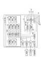
図1は、プロジェクター1の構成の一例を示す図である。
プロジェクター1は、スクリーンSCに画像光を投射することにより、スクリーンSCに投射画像PPを投射して表示する表示装置である。プロジェクター1は投射画像PPとして、静止画像と映像、すなわち動画像とのいずれを投射してもよく、以下の説明では「映像」又は「画像」と記載する。プロジェクター1は、静止画像を投射する場合であっても、画像形成部20によって、設定されたフレームレートで投射画像PPを更新するため、静止画像であっても映像であっても実質的な動作は相違はない。[1. Projector configuration]
[1-1. Overall configuration of projector]
FIG. 1 is a diagram showing an example of the configuration of the projector 1.
The projector 1 is a display device that projects and displays a projected image PP on the screen SC by projecting image light on the screen SC. The projector 1 may project either a still image or a video, that is, a moving image as the projected image PP, and will be described as “video” or “image” in the following description. Even when the projector 1 projects a still image, the
スクリーンSCは、建物の室内の壁面、天井面、又は床面に設置される幕状のスクリーンであってもよいが、壁面をスクリーンSCとして利用してもよい。また、ホワイトボードや家具などの設置物の平面を、スクリーンSCとして利用してもよい。また、スクリーンSCは平面に限らず、曲面や、凹凸を有する面であってもよい。 The screen SC may be a curtain-shaped screen installed on the wall surface, ceiling surface, or floor surface of the interior of the building, but the wall surface may be used as the screen SC. Further, a flat surface of an installation object such as a whiteboard or furniture may be used as a screen SC. Further, the screen SC is not limited to a flat surface, and may be a curved surface or a surface having irregularities.
プロジェクター1は、投射画像PPの映像ソースとして、後述するメモリー10Bに記憶した映像データを用いることができる。また、プロジェクター1の映像ソースは、映像供給装置2からプロジェクター1に入力される映像信号、データ出力装置3からプロジェクター1に入力される映像データ、及び、記憶媒体4に記憶された映像データ等から選択できる。 The projector 1 can use the video data stored in the memory 10B, which will be described later, as the video source of the projected image PP. The video source of the projector 1 is based on a video signal input from the
映像供給装置2は、ケーブル又は無線通信回線を介して、プロジェクター1に接続され、プロジェクター1に対して、アナログ映像信号、又はディジタル映像信号を出力する。ここで、アナログ映像信号は、例えば、D−SubコネクターやD端子を介して伝送されるアナログ映像信号、コンポジット映像信号等である。ディジタル映像信号は、例えば、各種デジタルインターフェースを介して伝送される信号である。
具体的には、HDMI(登録商標)、DVI、Displayport(登録商標)等により伝送される信号が挙げられる。また、Miracast(登録商標)、WirelessHD(登録商標)等の無線インターフェースを介して、映像供給装置2からプロジェクター1にディジタル映像信号が入力される構成であってもよい。
以下の説明では、アナログ映像信号及びディジタル映像信号を総称して映像信号と呼ぶ。映像供給装置2は、例えば、DVD(Digital Versatile Disc)プレイヤー等の映像再生装置、デジタルテレビチューナー等の放送受信装置、ビデオゲーム機やパーソナルコンピューター等で構成される。また、映像供給装置2は、パーソナルコンピューター等と通信して映像データを受信する通信装置等で構成されてもよい。The
Specific examples thereof include signals transmitted by HDMI (registered trademark), DVI, Displayport (registered trademark) and the like. Further, a digital video signal may be input from the
In the following description, analog video signals and digital video signals are collectively referred to as video signals. The
データ出力装置3は、映像のディジタルデータをプロジェクター1に出力する装置であり、例えば、MPEG形式でエンコードされたファイルをプロジェクター1に出力する。データ出力装置3は、映像のディジタルデータをファイル形式で入出力可能な装置であればよく、具体的には、パーソナルコンピューター、DVDプレイヤー、HDD(Hard Disk Drive)レコーダー等で構成される。 The data output device 3 is a device that outputs digital video data to the projector 1, and outputs, for example, a file encoded in the MPEG format to the projector 1. The data output device 3 may be any device capable of inputting / outputting digital video data in a file format, and specifically includes a personal computer, a DVD player, an HDD (Hard Disk Drive) recorder, and the like.
記憶媒体4は、半導体記憶デバイス、磁気的記憶装置、或いは、光学的記憶媒体等で構成され、データを不揮発的に記憶する。例えば、記憶媒体4は、DVD等の光学的記憶媒体、USBメモリー等のメモリーデバイス、SD(登録商標)カード等のカード型記憶媒体であってもよい。 The
プロジェクター1は、制御部10、画像形成部20、操作部31、媒体読取部32、I/F部33、映像I/F部34、及び、映像処理部40を備える。 The projector 1 includes a
制御部10は、CPU(Central Processing Unit)等のプロセッサー10Aを備え、このプロセッサー10Aが実行する制御プログラム等を不揮発的に記憶するROM(Read Only Memory)、プロセッサー10Aが使用するワークエリアを形成するRAM(Random Access Memory)等のメモリー10Bを備える。制御部10は、プロセッサー10Aが、メモリー10Bが記憶する制御プログラムを実行することによって、プロジェクター1の各部を制御して、投射画像PPの投射に係る各種動作を実行させる。なお、制御部10は複数のプロセッサーを備えていてもよい。 The
メモリー10Bは、半導体記憶デバイスや磁気的記憶装置を備え、制御部10のプロセッサーにより実行される制御プログラムや、プロセッサー10Aにより処理されるデータを不揮発的に記憶する。メモリー10Bは、設定データ、及び映像データを記憶する。設定データは、プロジェクター1の動作に関して設定される情報を含む。
映像データは、投射画像PPの映像ソースとして利用可能な映像データであり、例えば、データ出力装置3からプロジェクター1に入力される映像データと同様に、ファイル形式のデータである。映像データは、データ出力装置3からプロジェクター1に入力される映像データを、制御部10が取得して、メモリー10Bに記憶させたデータであってもよい。The memory 10B includes a semiconductor storage device and a magnetic storage device, and non-volatilely stores a control program executed by the processor of the
The video data is video data that can be used as a video source of the projected image PP, and is, for example, file format data like the video data input from the data output device 3 to the projector 1. The video data may be data acquired by the
操作部31は、プロジェクター1の機能に関するユーザーの入力操作を受け付ける。操作部31は、例えば、プロジェクター1の本体に設けられる操作パネルにより構成され、操作パネルに配置される各種スイッチに対する操作を検出し、操作信号を制御部10に出力する。
また、操作部31は、プロジェクター1のリモコン装置が送信する赤外線信号を受光する受光部を備える構成であってもよい。この場合には、操作部31は、リモコン装置から受光した赤外線信号をデコードし、リモコン装置の操作に対応する操作信号を制御部10に出力する。The
Further, the
媒体読取部32は、記憶媒体4に記憶されたデータを読み出すインターフェース回路である。媒体読取部32は、記憶媒体4に対するデータの書き込みやデータの消去が可能な構成であってもよい。媒体読取部32は、制御部10の制御に従って、映像ソースとして記憶媒体4に記憶された映像データを読み取り、制御部10に出力する。
媒体読取部32は、例えば、USBメモリーとしての記憶媒体4を接続するUSB(Universal Serial Bus)コネクター、カード型の記憶媒体4を装着するカードスロット、DVD等の光学的記憶媒体を再生するドライブ等を備えてもよい。The
The
I/F部33は、データ出力装置3に接続されるインターフェース回路であり、例えば、公知のデータ通信インターフェースを用いて構成される。具体的には、通信ケーブルによりデータ出力装置3に接続可能なUSBインターフェース、LAN(Local Area Network、イーサネット(登録商標)を含む)インターフェース、IEEE1394インターフェース等であってもよい。
また、I/F部33は、無線通信回線を利用した無線通信インターフェース回路であってもよい。具体的には、Wi−Fi(登録商標)を含む無線LAN、Bluetooth(登録商標)、ZigBee(登録商標)等で通信を行う通信インターフェースを備えて構成されてもよい。
I/F部33は、データ出力装置3に接続された場合に、データ出力装置3の接続を検出する機能、データ出力装置3との間で通信を確立する機能、データ出力装置3に対する電源供給機能等を実行するインターフェース回路を備えてもよい。
制御部10は、I/F部33により、データ出力装置3との間でデータ通信を実行し、データ出力装置3が出力する映像データを取得できる。The I /
Further, the I /
The I /
The
映像I/F部34は、映像供給装置2に接続されるインターフェース回路であり、例えば、公知の映像入力インターフェース回路を用いて構成される。具体的には、上述したD−Subコネクター、D端子、コンポジット映像端子、HDMI、DVI、Displayport等のインターフェース回路等を備える。また、Miracast、WirelessHD等の無線インターフェース回路であってもよい。
映像I/F部34は、映像供給装置2から入力される映像信号を映像処理部40に出力する。また、映像I/F部34は、制御部10の制御に従って、映像供給装置2との間でデータ通信を実行し、映像供給装置2の機種やベンダー名称の判別、映像供給装置2から入力される映像信号に関する情報の取得等を行ってもよい。The video I /
The video I /
投射画像PPを形成する画像形成部20は、投射部25、光源制御部27、及び、光変調装置駆動部28を備え、投射部25は光源21、光変調装置22、及び投射光学系23を含む。 The
光源21は、キセノンランプ、超高圧水銀ランプ等のランプ類、或いは、LEDやレーザー光源等の固体光源で構成される。光源21は、光源制御部27から供給される電力により点灯し、光変調装置22に向けて光を発する。光源制御部27は、制御部10の制御に従って、光源21の発光輝度を調整できる。 The
光変調装置22は、光源21が発する光を変調して画像光を生成し、画像光を投射光学系23に照射する。本実施形態では、光変調装置22が、赤色(R)、緑色(G)、及び、青色(B)の各色に対応する3つの液晶パネルを備え、光源21が発した光を液晶パネルに透過させる構成を例示する。
光変調装置22の3つの液晶パネルには光変調装置駆動部28が接続される。光変調装置駆動部28は、映像処理部40が出力する映像信号に基づき、液晶パネルの各画素を駆動して、液晶パネルにフレーム(画面)単位で画像を描画する。The
The optical
光源21と光変調装置22との間の光路又は光変調装置22には、リフレクター、レンズ群、偏光板、調光素子等を設けてもよい。また、光変調装置22は、反射型の液晶パネルを用いる構成とすることができる。この場合には、光変調装置22は、光源21が発する光を液晶パネルに反射させ、反射光を投射光学系23に導く。また、光変調装置22を、デジタルミラーデバイス(DMD)を用いる構成とすることもでき、1枚のDMDとカラーホイールを備える構成としてもよい。また、光変調装置22は反射型の液晶表示パネルを備える構成であってもよい。 A reflector, a lens group, a polarizing plate, a dimming element, or the like may be provided in the optical path between the
投射光学系23は、光変調装置22により変調された画像光をスクリーンSCに向けて投射し、スクリーンSC上で投射画像PPを結像させる。投射光学系23は、例えば、3つの液晶パネルを通った光を合成するプリズム、画像光を導くレンズ群やミラー等の光学素子を有する構成としてもよい。更に、投射光学系23は、ズーム機構や焦点調整のための機構を備えてもよい。 The projection
映像処理部40は、制御部10の制御に従って、映像ソースから映像信号を生成して光変調装置駆動部28に出力する。
制御部10が選択した映像ソースが、映像I/F部34に入力される映像信号である場合には、映像処理部40には、映像I/F部34から映像信号が入力される。また、制御部10が選択した映像ソースが、記憶媒体4又は記憶部11に記憶された映像データ又はデータ出力装置3から入力される映像データである場合には、映像処理部40には制御部10から映像データが入力される。The
When the video source selected by the
制御部10は、メモリー10Bが記憶する制御プログラムを実行し、操作部31により受け付けられたユーザーの操作に従って、プロジェクター1の映像ソースを選択し、選択した映像ソースに基づく映像を画像形成部20によって投射して、スクリーンSCに表示させる。
制御部10は、映像ソースとして映像供給装置2を選択した場合には、映像I/F部34及び映像処理部40を制御して、映像供給装置2から映像I/F部34に入力される映像信号の処理を実行させる。これにより、映像処理部40から光変調装置駆動部28に映像信号が出力され、映像信号に対応する映像が画像形成部20により投射される。The
When the
また、制御部10は、映像ソースとして、データ出力装置3が出力する映像データを選択した場合には、この映像データを取得して映像処理部40に出力する。制御部10は、映像ソースとして記憶媒体4に記憶された映像データ又は記憶部11に記憶された映像データを選択した場合には、これらの映像データの読み取りを行い、映像処理部40に出力する。これらの場合には、制御部10は、映像処理部40を制御して映像データを処理させ、映像データに基づき画像形成部20により映像を投射させる。 When the
また、制御部10は、映像ソースに対して合成するマスク画像MPを、後述するマスク記憶部151から読み出して、映像処理部40に出力する。マスク画像MPとは、複数の画素毎に、透過率Tが設定された画像を示す。マスク画像MPは、フィルター処理を実行するフィルター画像と言い換えることができる。 Further, the
[1−2.制御部の構成]
制御部10は、輝度調整部111、判定部112、区分部113、第1置換部121、第2置換部122、第3置換部123、第4置換部124、第5置換部125、第6置換部126、第7置換部127、第8置換部128、生成部131、選択部132、及びマスク記憶部151を備える。具体的には、制御部10のプロセッサー10Aが、メモリー10Bが記憶する制御プログラムを実行することによって、輝度調整部111、判定部112、区分部113、第1置換部121、第2置換部122、第3置換部123、第4置換部124、第5置換部125、第6置換部126、第7置換部127、第8置換部128、生成部131、及び選択部132として機能する。また、制御部10のプロセッサー10Aが、メモリー10Bが記憶する制御プログラムを実行することによって、メモリー10Bをマスク記憶部151として機能させる。[1-2. Control unit configuration]
The
マスク記憶部151は、生成部131によって生成されたマスク画像MPを記憶する。マスク記憶部151に記憶されたマスク画像MPは、選択部132によって読み出される。 The
輝度調整部111は、元画像PAの画素の第1輝度値BA1が最大輝度値BXになり、元画像PAの画素の第3輝度値BA3が最小輝度値BNになるように、元画像PAの画素の輝度値BAを調整する。
第1輝度値BA1は、元画像PAを構成する画素の輝度値BAのうち、最大の輝度値を示す。第3輝度値BA3は、元画像PAを構成する画素の輝度値BAのうち、最小の輝度値を示す。
換言すれば、輝度調整部111は、輝度値BAの範囲を、第1輝度値BA1から第3輝度値BA3までの範囲から、最小輝度値BNから最大輝度値BXまでの範囲に調整する。
輝度値BAが256諧調である場合には、最大輝度値BXは、輝度値BAが「255」を示し、最小輝度値BNは、輝度値BAが「0」を示す。
輝度調整部111は、元画像PAの画素の輝度値BAを、例えば、次の式(1)で調整し、調整後の輝度値Bを算出する。
B=(BX−BN)×BA/(BA1−BA3)+α (1)
ただし、係数αは次の式(2)で表わされる。
α=(BN×BA1−BX×BA3)/(BA1−BA3) (2)The
The first luminance value BA1 indicates the maximum luminance value among the luminance values BA of the pixels constituting the original image PA. The third luminance value BA3 indicates the smallest luminance value among the luminance values BA of the pixels constituting the original image PA.
In other words, the
When the luminance value BA is 256 gradations, the maximum luminance value BX indicates the luminance value BA “255”, and the minimum luminance value BN indicates the luminance value BA “0”.
The
B = (BX-BN) x BA / (BA1-BA3) + α (1)
However, the coefficient α is expressed by the following equation (2).
α = (BN × BA1-BX × BA3) / (BA1-BA3) (2)
判定部112は、輝度調整部111によって輝度値BAが輝度値Bに調整された元画像PAにおいて、元画像PAの外縁を構成する画素の輝度値Bが、第2輝度値B2であるか否かを判定する。
なお、以下の説明では、輝度調整部111によって輝度値BAが輝度値Bに調整された元画像PAを、単に元画像PAと記載する場合がある。
第2輝度値B2は、第1輝度値B1より小さい輝度値Bであって、第3輝度値B3より大きい輝度値Bを示す。第1輝度値B1は、元画像PAを構成する画素の輝度値Bのうち、最大の輝度値Bを示す。第1輝度値B1は、最大輝度値BXである。第3輝度値B3は、元画像PAを構成する画素の輝度値Bのうち、最小の輝度値Bを示す。第3輝度値B3は、最小輝度値BNである。
判定部112の処理については、後述にて図4を参照して詳細に説明する。In the original image PA whose brightness value BA is adjusted to the brightness value B by the
In the following description, the original image PA whose luminance value BA is adjusted to the luminance value B by the
The second luminance value B2 is a luminance value B smaller than the first luminance value B1 and indicates a luminance value B larger than the third luminance value B3. The first luminance value B1 indicates the maximum luminance value B among the luminance values B of the pixels constituting the original image PA. The first luminance value B1 is the maximum luminance value BX. The third luminance value B3 indicates the smallest luminance value B among the luminance values B of the pixels constituting the original image PA. The third luminance value B3 is the minimum luminance value BN.
The processing of the
区分部113は、輝度調整部111によって輝度値BAが輝度値Bに調整された元画像PAにおいて、元画像PAの各画素の輝度値Bを第1輝度値B1、第2輝度値B2、及び第3輝度値B3に区分する。第2輝度値B2は、第1輝度値B1より小さく、第3輝度値B3は、第2輝度値B2より小さい。
第1輝度値B1は、最大輝度値BXであり、第3輝度値B3は、最小輝度値BNであり、第2輝度値B2は、中間諧調の輝度値Bを示す。輝度値Bが256諧調である場合には、中間諧調の輝度値Bは、1以上254以下である。In the original image PA whose brightness value BA is adjusted to the brightness value B by the
The first luminance value B1 is the maximum luminance value BX, the third luminance value B3 is the minimum luminance value BN, and the second luminance value B2 indicates the luminance value B in the intermediate gradation. When the luminance value B is 256 gradations, the luminance value B of the intermediate gradation is 1 or more and 254 or less.
第1置換部121は、元画像PAにおいて、第2輝度値B2に対応する画素の輝度値Bを、第3輝度値B3に置換して第1画像P1を生成する。元画像PAにおいて第2輝度値B2に対応する画素とは、元画像PAにおいて輝度値Bが第2輝度値B2である画素を示す。
換言すれば、第1置換部121は、元画像PAにおいて輝度値Bが第2輝度値B2である画素に対して、その輝度値Bを第2輝度値B2から第3輝度値B3に置換することによって第1画像P1を生成する。
第1置換部121の処理については、後述にて図5を参照して詳細に説明する。The
In other words, the
The processing of the
第2置換部122は、元画像PAにおいて、第2輝度値B2に対応する画素の輝度値Bを、第1輝度値B1に置換して第2画像P2を生成する。
換言すれば、第2置換部122は、元画像PAにおいて輝度値Bが第2輝度値B2である画素に対して、その輝度値Bを第2輝度値B2から第1輝度値B1に置換することによって第2画像P2を生成する。
第2置換部122の処理については、後述にて図5を参照して詳細に説明する。The
In other words, the
The processing of the
第3置換部123は、元画像PAにおいて、第2輝度値B2に対応する画素の輝度値Bを、第3輝度値B3に置換すると共に、第3輝度値B3に対応する画素の輝度値Bを、第2輝度値B2に置換して第3画像P3を生成する。元画像PAにおいて第3輝度値B3に対応する画素とは、元画像PAにおいて輝度値Bが第3輝度値B3である画素を示す。
換言すれば、第3置換部123は、元画像PAにおいて輝度値Bが第2輝度値B2である画素に対して、その輝度値Bを第2輝度値B2から第3輝度値B3に置換すると共に、元画像PAにおいて輝度値Bが第3輝度値B3である画素に対して、その輝度値Bを第3輝度値B3から第2輝度値B2に置換することによって第3画像P3を生成する。
第3置換部123の処理については、後述にて図6を参照して詳細に説明する。In the original image PA, the
In other words, the
The processing of the
第4置換部124は、元画像PAにおいて、第2輝度値B2に対応する画素の輝度値Bを、第1輝度値B1に置換すると共に、第1輝度値B1に対応する画素の輝度値Bを、第2輝度値B2に置換して第4画像P4を生成する。第1輝度値B1に対応する画素とは、元画像PAにおいて輝度値Bが第1輝度値B1である画素を示す。
換言すれば、第4置換部124は、元画像PAにおいて輝度値Bが第2輝度値B2である画素に対して、その輝度値Bを第2輝度値B2から第1輝度値B1に置換すると共に、元画像PAにおいて輝度値Bが第1輝度値B1である画素に対して、その輝度値Bを第1輝度値B1から第2輝度値B2に置換することによって第4画像P4を生成する。
第4置換部124の処理については、後述にて図6を参照して詳細に説明する。In the original image PA, the
In other words, the
The processing of the
第5置換部125は、第1画像P1において、第3輝度値B3に対応する画素の輝度値Bを、第1輝度値B1に置換すると共に、第1輝度値B1に対応する画素の輝度値Bを、第3輝度値B3に置換して第5画像P5を生成する。第1画像P1において第3輝度値B3に対応する画素とは、第1画像P1において輝度値Bが第3輝度値B3である画素を示す。また、第1画像P1において第1輝度値B1に対応する画素とは、第1画像P1において輝度値Bが第1輝度値B1である画素を示す。
換言すれば、第5置換部125は、第1画像P1において輝度値Bが第3輝度値B3である画素に対して、その輝度値Bを第3輝度値B3から第1輝度値B1に置換すると共に、第1画像P1において輝度値Bが第1輝度値B1である画素に対して、その輝度値Bを第1輝度値B1から第3輝度値B3に置換することによって第5画像P5を生成する。
第5置換部125の処理については、後述にて図7を参照して詳細に説明する。In the first image P1, the
In other words, the
The processing of the
第6置換部126は、第2画像P2において、第3輝度値B3に対応する画素の輝度値Bを、第1輝度値B1に置換すると共に、第1輝度値B1に対応する画素の輝度値Bを、第3輝度値B3に置換して第6画像P6を生成する。第2画像P2において第3輝度値B3に対応する画素とは、第2画像P2において輝度値Bが第3輝度値B3である画素を示す。また、第2画像P2において第1輝度値B1に対応する画素とは、第2画像P2において輝度値Bが第1輝度値B1である画素を示す。
換言すれば、第6置換部126は、第2画像P2において輝度値Bが第3輝度値B3である画素に対して、その輝度値Bを第3輝度値B3から第1輝度値B1に置換すると共に、第2画像P2において輝度値Bが第1輝度値B1である画素に対して、その輝度値Bを第1輝度値B1から第3輝度値B3に置換することによって第6画像P6を生成する。
第6置換部126の処理については、後述にて図7を参照して詳細に説明する。In the second image P2, the
In other words, the
The processing of the
第7置換部127は、第3画像P3において、第3輝度値B3に対応する画素の輝度値Bを、第1輝度値B1に置換すると共に、第1輝度値B1に対応する画素の輝度値Bを、第3輝度値B3に置換して第7画像P7を生成する。第3画像P3において第3輝度値B3に対応する画素とは、第3画像P3において輝度値Bが第3輝度値B3である画素を示す。また、第3画像P3において第1輝度値B1に対応する画素とは、第3画像P3において輝度値Bが第1輝度値B1である画素を示す。
換言すれば、第7置換部127は、第3画像P3において輝度値Bが第3輝度値B3である画素に対して、その輝度値Bを第3輝度値B3から第1輝度値B1に置換すると共に、第3画像P3において輝度値Bが第1輝度値B1である画素に対して、その輝度値Bを第1輝度値B1から第3輝度値B3に置換することによって第7画像P7を生成する。
第7置換部127の処理については、後述にて図8を参照して詳細に説明する。In the third image P3, the
In other words, the
The processing of the
第8置換部128は、第4画像P4において、第3輝度値B3に対応する画素の輝度値Bを、第1輝度値B1に置換すると共に、第1輝度値B1に対応する画素の輝度値Bを、第3輝度値B3に置換して第8画像P8を生成する。第4画像P4において第3輝度値B3に対応する画素とは、第4画像P4において輝度値Bが第3輝度値B3である画素を示す。また、第4画像P4において第1輝度値B1に対応する画素とは、第4画像P4において輝度値Bが第1輝度値B1である画素を示す。
換言すれば、第8置換部128は、第4画像P4において輝度値Bが第3輝度値B3である画素に対して、その輝度値Bを第3輝度値B3から第1輝度値B1に置換すると共に、第4画像P4において輝度値Bが第1輝度値B1である画素に対して、その輝度値Bを第1輝度値B1から第3輝度値B3に置換することによって第8画像P8を生成する。
第8置換部128の処理については、後述にて図8を参照して詳細に説明する。In the fourth image P4, the
In other words, the
The processing of the
生成部131は、元画像PAの外縁を構成する画素の輝度値Bが、第2輝度値B2ではないと判定部112が判定した場合に、元画像PAにおいて、各画素の輝度値Bを透過率Tに変換してマスク画像MPAを生成する。
また、生成部131は、元画像PAの外縁を構成する画素の輝度値Bが、第2輝度値B2であると判定部112が判定した場合に、第1画像P1及び第2画像P2の各々において、各画素の輝度値Bを透過率Tに変換してマスク画像MPを生成する。具体的には、生成部131は、第1画像P1の各画素の輝度値Bを透過率Tに変換して第1マスク画像MP1を生成する。また、生成部131は、第2画像P2の各画素の輝度値Bを透過率Tに変換して第2マスク画像MP2を生成する。
また、生成部131は、第3画像P3及び第4画像P4の各々において、各画素の輝度値Bを透過率Tに変換してマスク画像MPを生成する。具体的には、生成部131は、第3画像P3の各画素の輝度値Bを透過率Tに変換して第3マスク画像MP3を生成する。また、生成部131は、第4画像P4の各画素の輝度値Bを透過率Tに変換して第4マスク画像MP4を生成する。When the
Further, when the
Further, the
また、生成部131は、第5画像P5、第6画像P6、第7画像P7及び第8画像P8の各々において、各画素の輝度値Bを透過率Tに変換してマスク画像MPを生成する。具体的には、生成部131は、第5画像P5の各画素の輝度値Bを透過率Tに変換して第5マスク画像MP5を生成する。また、生成部131は、第6画像P6の各画素の輝度値Bを透過率Tに変換して第6マスク画像MP6を生成する。また、生成部131は、第7画像P7の各画素の輝度値Bを透過率Tに変換して第7マスク画像MP7を生成する。また、生成部131は、第8画像P8の各画素の輝度値Bを透過率Tに変換して第8マスク画像MP8を生成する。
また、生成部131は、生成したマスク画像MPA、及び、第1マスク画像MP1〜第8マスク画像MP8をマスク記憶部151に記録する。
なお、輝度値Bを透過率Tに変換する方法は、下記の2つの方法がある。第1の方法では、輝度値Bが大きい程、透過率Tが大きくなるように、輝度値Bを透過率Tに変換する。第2の方法では、輝度値Bが大きい程、透過率Tが小さくなるように、輝度値Bを透過率Tに変換する。本実施形態では、第1の方法で輝度値Bを透過率Tに変換する場合について説明する。Further, the
Further, the
There are the following two methods for converting the luminance value B into the transmittance T. In the first method, the luminance value B is converted into the transmittance T so that the larger the luminance value B is, the larger the transmittance T is. In the second method, the luminance value B is converted into the transmittance T so that the larger the luminance value B is, the smaller the transmittance T is. In the present embodiment, the case where the luminance value B is converted into the transmittance T by the first method will be described.
選択部132は、ユーザーからの操作に基づいて、第1マスク画像MP1〜第8マスク画像MP8の中から1つのマスク画像MPSを選択する。選択されたマスク画像MPSは、映像処理部40によって、入力画像PBと合成され、合成画像PCが生成され、合成画像PCがスクリーンSCに投射される。
映像処理部40については、後述にて図2を参照して詳細に説明する。The
The
本実施形態では、生成部131が、第1マスク画像MP1〜第8マスク画像MP8を生成するが、本発明の実施形態は、これに限定されない。生成部131が、少なくとも、第1マスク画像MP1及び第2マスク画像MP2を生成すればよい。生成部131が、例えば、第1マスク画像MP1〜第4マスク画像MP4を生成してもよい。 In the present embodiment, the
また、本実施形態では、生成部131は、輝度値Bが大きい程、透過率Tが大きくなるように、輝度値Bを透過率Tに変換するが、本発明の実施形態は、これに限定されない。生成部131が、輝度値Bを透過率Tに変換すればよい。生成部131が、例えば、輝度値Bが大きい程、透過率Tが小さくなるように、輝度値Bを透過率Tに変換してもよい。 Further, in the present embodiment, the
[1−3.映像処理部の構成]
図2は、映像処理部40の構成の一例を示す図である。図2の実線矢印は映像信号の流れを示し、破線矢印は映像データの流れを示し、一点鎖線矢印は後述するマスク画像データの流れを示す。また、図2に示す入力画像PB、マスク画像MPS、及び合成画像PCについては、図3を参照して更に説明する。マスク画像データは、マスク画像MPSを示す。[1-3. Video processing unit configuration]
FIG. 2 is a diagram showing an example of the configuration of the
図2に示すように、映像処理部40は、映像信号入力部41、信号処理部42、OSD生成部43、映像補正部44、データ入力部45、映像デコード部46、画像入力部47、及び、画像メモリー48を備える。
映像処理部40は、図2に示す各機能部に対応するハードウェアを備える回路であってもよいし、これらの回路を集積したIC(Integrated Circuit)、FPGA(Field−Programmable Gate Array)等のプログラマブルデバイスであってもよい。また、映像処理部40は、プログラムを実行するプロセッサーを備え、このプロセッサーがプログラムを実行して、図2に示す機能部をソフトウェアとハードウェアとの協働により実現する構成であってもよい。As shown in FIG. 2, the
The
映像処理部40が備える映像信号入力部41、信号処理部42、OSD生成部43、及び映像補正部44の各処理部は、フレームメモリーに接続されてもよい。この場合には、映像処理部40の各部は、映像信号に基づき、映像の1フレームを構成する画像をフレームメモリーに展開し、各種処理を実行する。
フレームメモリーは、複数のフレームに相当する画像を格納可能な容量を有するものであってもよい。また、フレームメモリーは、例えば、制御部10が備えるRAMの一部の記憶領域を用いて構成されてもよいし、映像処理部40に、図示しないメモリーバスやDRAM(Dynamic Random Access Memory)コントローラーを介してDRAMを接続して、フレームメモリーとして機能させてもよい。Each processing unit of the video
The frame memory may have a capacity capable of storing images corresponding to a plurality of frames. Further, the frame memory may be configured by using, for example, a part of the storage area of the RAM included in the
映像信号入力部41は、映像I/F部34から入力される映像信号に対し、プロジェクター1の信号処理に適した信号形式、すなわち信号フォーマット、への変換等の処理を実行し、信号処理部42に出力する。 The video
信号処理部42は、制御部10の制御に従って、映像信号入力部41から入力される映像信号に対し、映像の明るさが設定された状態に変換する明るさ変換処理や色変換処理を実行する。また、信号処理部42は、映像信号に対するノイズ除去処理を実行してもよい。信号処理部42は、処理後の映像信号をOSD生成部43に出力する。 Under the control of the
データ入力部45は、制御部10から入力される映像データを取得し、映像デコード部46に出力する。データ入力部45に入力される映像データは、制御部10が、ファイル形式の映像データに基づいて映像処理部40に入力する映像データである。映像デコード部46は、データ入力部45から入力される映像データをデコードして、信号処理部42における信号処理に適した映像信号に変換して、変換後の映像信号を信号処理部42に出力する。映像デコード部46には、例えば、ファイル形式の映像データから生成される映像ストリームが入力される。ファイル形式の映像データから映像ストリームを生成する処理は、制御部10が実行してもよいし、データ入力部45が実行してもよい。 The
また、制御部10は、マスク画像データを映像処理部40に出力する。マスク画像データは画像入力部47に入力され、画像入力部47は、マスク画像データに基づきマスク画像MPSを画像メモリー48に書き込む。マスク画像MPSは、図1に示す選択部132によって選択されたマスク画像MPに対応する。
画像メモリー48は、マスク画像MPSを一時的に格納する一時記憶領域であり、映像処理部40が内蔵する揮発性メモリー、又は、映像処理部40に接続されるDRAM等によって構成される。画像メモリー48は、上述したフレームメモリーの一部であってもよいし、フレームメモリーと同じメモリーの記憶領域を使って構成されてもよい。Further, the
The
OSD生成部43は、画像を合成する処理を行う。OSD生成部43は、信号処理部42から入力される映像信号から1フレーム分の画像を抽出し、合成処理の対象の画像、すなわち、入力画像PBとする。OSD生成部43は、入力画像PBに対し、OSD画像を重畳する。OSD生成部43は、合成画像PCの映像信号を映像補正部44に出力する。 The
映像補正部44は、OSD生成部43が出力する合成画像PCに対し、制御部10の制御に従って、幾何補正処理等の各種補正処理を実行し、画像形成部20に出力する。映像補正部44が実行する補正処理は、例えば、キーストーン補正や樽形歪み補正が挙げられる。 The
OSD画像は、例えば、プロジェクター1の機能を設定するためのメニュー画面、プロジェクター1の動作状態を報知するメッセージ画面等を構成する画像である。OSD画像の画像データは、予め記憶部11に記憶され、制御部10が記憶部11に記憶されるOSD画像を読み出して映像処理部40に出力してもよい。また、制御部10が、プロジェクター1の入力ソースの状態、エラー状態、又は操作部31の操作等に対応して、OSD画像のデータを生成し、映像処理部40に出力してもよい。このOSD画像のデータは、例えば、画像入力部47に入力され、画像入力部47によって画像メモリー48に書き込まれる。制御部10は、OSD生成部43を制御してOSD画像を重畳する処理を実行させる。 The OSD image is, for example, an image constituting a menu screen for setting the function of the projector 1, a message screen for notifying the operating state of the projector 1, and the like. The image data of the OSD image may be stored in the storage unit 11 in advance, and the
OSD生成部43は、信号処理部42から入力される映像を構成する各フレームにOSD画像を重畳する。ここで、OSD生成部43は、入力される映像の全てのフレームに画像を重畳してもよいし、一部のフレームに画像を重畳してもよい。 The
また、OSD生成部43は、制御部10の制御に従って、信号処理部42から入力される映像のフレームに、画像メモリー48に書き込まれたマスク画像MPSを重畳して合成画像PCを生成することも可能である。 Further, the
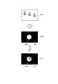
図3は、プロジェクター1が画像を合成する処理の一例を示す図である。画像を合成する処理は、OSD生成部43によって実行される。
入力画像PBは、OSD生成部43に入力される映像信号に基づき生成される画像の一例である。合成画像PCは、入力画像PBにマスク画像MPSを重畳して得られる。FIG. 3 is a diagram showing an example of a process in which the projector 1 synthesizes images. The process of synthesizing the images is executed by the
The input image PB is an example of an image generated based on the video signal input to the
入力画像PB、マスク画像MPS、及び合成画像PCの各々は、複数の画素を有する画像である。入力画像PBは、例えば、RGB24ビットフルカラーの画像であり、入力画像PBのデータは画素毎のR、G、Bの階調データを含む。 Each of the input image PB, the mask image MPS, and the composite image PC is an image having a plurality of pixels. The input image PB is, for example, an RGB 24-bit full-color image, and the data of the input image PB includes R, G, and B gradation data for each pixel.
マスク画像MPSは、互いに相違する透過率Tを有する複数の領域を含む。1つの画素が1つの領域を構成してもよいし、複数の画素が1つの領域を構成してもよい。領域の位置、サイズ、形状は任意である。マスク画像MPSのデータは、領域毎の透過率Tを含む。透過率Tは、マスク画像MPSを入力画像PBの上層に重ねた場合に、入力画像PBが透過して見える程度を意味し、透明度と呼ぶこともできる。 The masked image MPS contains a plurality of regions having different transmittances T from each other. One pixel may form one area, or a plurality of pixels may form one area. The position, size, and shape of the area are arbitrary. The mask image MPS data includes the transmittance T for each region. The transmittance T means the degree to which the input image PB appears to be transparent when the mask image MPS is superposed on the upper layer of the input image PB, and can also be called transparency.
図3のマスク画像MPSは、互いに相違する透過率Tが設定された領域A21、及び、領域A22を含む。領域A21は透過率Tが0%に設定された領域である。領域A22は、透過率Tが100%に設定された領域である。マスク画像MPSは、領域A21と領域A22との境界に位置する画素間で透過率Tが0%から100%に変化する画像であってもよい。また、マスク画像MPSは、図3に例示するように、領域A21と領域A22との境界部に位置する複数の画素の透過率Tが、100%から0%まで段階的に変化するグラデーションを構成する画像であってもよい。この場合、領域A21と領域A22との境界に位置する各画素に対し、グラデーションを形成するように、透過率Tが設定される。 The mask image MPS of FIG. 3 includes a region A21 and a region A22 in which different transmittances T are set. The region A21 is a region in which the transmittance T is set to 0%. The region A22 is a region in which the transmittance T is set to 100%. The mask image MPS may be an image in which the transmittance T changes from 0% to 100% between the pixels located at the boundary between the area A21 and the area A22. Further, as illustrated in FIG. 3, the mask image MPS constitutes a gradation in which the transmittance T of a plurality of pixels located at the boundary between the area A21 and the area A22 changes stepwise from 100% to 0%. It may be an image to be used. In this case, the transmittance T is set so as to form a gradation for each pixel located at the boundary between the area A21 and the area A22.
マスク画像MPSは、透過率Tが100%の領域、すなわち領域A22では透明であり、透過率Tが100%未満の領域では着色されている。この色は任意であり、例えば、図3に示すように黒色としてもよいし、他の色であってもよい。また、1つのマスク画像MPSにおいて透過率Tが100%未満の領域に複数の色が配置されてもよい。
本実施形態では、マスク画像MPSの色が黒色で着色されている場合について説明する。The mask image MPS is transparent in the region where the transmittance T is 100%, that is, the region A22, and is colored in the region where the transmittance T is less than 100%. This color is arbitrary and may be, for example, black as shown in FIG. 3 or another color. Further, a plurality of colors may be arranged in a region where the transmittance T is less than 100% in one mask image MPS.
In the present embodiment, the case where the color of the mask image MPS is colored black will be described.
合成画像PCは、入力画像PBの上層にマスク画像MPSを重畳して合成された画像である。合成画像PCの領域A31は、マスク画像MPSの領域A21に対応する領域である。領域A21の透過率Tは0%であるため、合成画像PCの領域A31は、領域A21と同じ色の画素で構成される。これに対し、合成画像PCにおいて、マスク画像MPSにおける透過率Tが100%未満の領域では入力画像PBが透過する。このため、領域A32では、領域A22を透過して、入力画像PBの一部が現れている。 The composite image PC is an image synthesized by superimposing the mask image MPS on the upper layer of the input image PB. The area A31 of the composite image PC is an area corresponding to the area A21 of the mask image MPS. Since the transmittance T of the region A21 is 0%, the region A31 of the composite image PC is composed of pixels of the same color as the region A21. On the other hand, in the composite image PC, the input image PB is transmitted in the region where the transmittance T in the mask image MPS is less than 100%. Therefore, in the region A32, a part of the input image PB appears through the region A22.
図3の合成画像PCは、入力画像PBの一部分が明るく視認され、他の部分は暗く視認され、一部は視認できない状態であり、あたかも入力画像PBにスポットライトを当てたような視覚効果を有する。この視覚効果を、照明効果と呼ぶ。プロジェクター1は、入力画像PBに、透過率Tが設定されたマスク画像MPSを重畳することにより、入力画像PBに照明効果を付与してスクリーンSCに投射できる。 In the composite image PC of FIG. 3, a part of the input image PB is visually recognized brightly, the other part is visually recognized darkly, and a part is invisible, and the visual effect is as if the input image PB is spotlighted. Have. This visual effect is called a lighting effect. The projector 1 can give a lighting effect to the input image PB and project it on the screen SC by superimposing the mask image MPS having the transmittance T set on the input image PB.
図2に戻って、OSD生成部43の構成について説明する。図2に示すように、OSD生成部43は、形状調整部43a、及び、合成部43cを備える。図2は機能ブロック図であり、OSD生成部43が、形状調整部43a、及び合成部43cの各々として機能するハードウェアを備えてもよい。或いは、OSD生成部43が形状調整部43a、合成部43cの各機能に対応する処理を、図に示した順序で実行する構成であってもよい。すなわち、形状調整部43a、及び合成部43cはOSD生成部43が実行する機能及び処理を模式化して示すものであってもよい。換言すれば、OSD生成部43は、形状調整処理、及び、合成処理を順次実行するものであればよい。 Returning to FIG. 2, the configuration of the
形状調整部43aは、マスク画像MPSを画像メモリー48から取得し、マスク画像MPSに対し形状及びサイズを調整する処理を行う。この処理では、マスク画像MPの形状及びサイズを、光変調装置22の形状やサイズまたは解像度に適合させる。信号処理部42がOSD生成部43に出力する映像信号は、信号処理部42によって形状、サイズ、及び解像度が調整されている。形状調整部43aは、マスク画像MPSの形状、サイズ、及び解像度を、信号処理部42から入力される映像信号に合わせる。具体的には、マスク画像MPSの形状、サイズ、及び解像度の各々を、入力画像PBの形状、サイズ、及び解像度の各々と一致させる。 The
合成部43cは、信号処理部42から入力される入力画像PBの上層に、形状調整部43aによって調整されたマスク画像MPSを重ねて合成し、合成画像PCを生成して、映像補正部44に出力する。このように、プロジェクター1は、マスク画像MPSを利用して、OSD生成部43によって入力画像PBに照明効果を付与する。 The
OSD生成部43は、一般的なOSD表示機能を実現するため、上述したメニュー画面などのOSD画像を入力画像PBに重畳させて表示することも可能である。この場合には、制御部10は、OSD画像の画像データを、画像入力部47に出力し、画像入力部47はOSD画像を画像メモリー48に描画する。メニュー画面等のOSD画像を処理する場合、形状調整部43aは、画像メモリー48からOSD画像を取得して、OSD画像のサイズを入力画像PBのサイズや解像度に合わせて調整する。OSD画像の形状及びサイズは、入力画像PBと一致しなくてもよい。 In order to realize a general OSD display function, the
映像処理部40は、映像信号に対する信号処理を信号処理部42で実行し、照明効果を付与する映像処理をOSD生成部43で実行する。このように、入力画像PBに関する映像処理を、OSD生成部43とは別の処理部、すなわち、信号処理部42で実行するため、照明効果の影響を受けずに映像信号を処理できるという利点がある。 The
本実施形態では、図1を参照して説明したように、制御部10が、輝度調整部111、判定部112、区分部113、第1置換部121、第2置換部122、第3置換部123、第4置換部124、第5置換部125、第6置換部126、第7置換部127、第8置換部128、生成部131、選択部132、及びマスク記憶部151を備えるが、本発明の実施形態は、これに限定されない。図1に示す制御部10、及び、図2に示す映像処理部40の一方が、輝度調整部111、判定部112、区分部113、第1置換部121、第2置換部122、第3置換部123、第4置換部124、第5置換部125、第6置換部126、第7置換部127、第8置換部128、生成部131、選択部132、及びマスク記憶部151を備えればよい。例えば、映像処理部40が、輝度調整部111、判定部112、区分部113、第1置換部121、第2置換部122、第3置換部123、第4置換部124、第5置換部125、第6置換部126、第7置換部127、第8置換部128、生成部131、選択部132、及びマスク記憶部151を備えてもよい。この場合には、輝度調整部111、判定部112、区分部113、第1置換部121、第2置換部122、第3置換部123、第4置換部124、第5置換部125、第6置換部126、第7置換部127、第8置換部128、及び、生成部131は、例えば、図2の画像入力部47と、画像メモリー48との間に配置される。 In the present embodiment, as described with reference to FIG. 1, the
[2.制御部及び映像処理部の処理の具体例]
[2−1.判定部の処理]
次に、図4〜図10を参照して、制御部10及び映像処理部40の処理の具体例について説明する。
図4は、元画像PAの一例を示す図である。図4を参照して、図1に示す判定部112の処理の具体例について説明する。なお、図4に示す元画像PAは、図1に示す輝度調整部111によって輝度が調整された元画像PAを示す。すなわち、元画像PAの輝度値Bの最大値は、最大輝度値BXであり、元画像PAの輝度値Bの最小値は、最小輝度値BNである。
図4に示すように、元画像PAは、第1領域AR1、第2領域SR2、及び、第3領域SR3を含む。第3領域SR3は、元画像PAにおいて最も外側に配置され、元画像PAの外縁を含む。第2領域SR2は、第3領域SR3の内側に配置され、第1領域AR1は、第2領域SR2の内側に配置される。[2. Specific examples of processing in the control unit and video processing unit]
[2-1. Judgment section processing]
Next, specific examples of processing by the
FIG. 4 is a diagram showing an example of the original image PA. A specific example of the processing of the
As shown in FIG. 4, the original image PA includes the first region AR1, the second region SR2, and the third region SR3. The third region SR3 is arranged on the outermost side of the original image PA and includes the outer edge of the original image PA. The second region SR2 is arranged inside the third region SR3, and the first region AR1 is arranged inside the second region SR2.
第1領域AR1の輝度値Bは、第1輝度値B1であり、第2領域SR2の輝度値Bは、第3輝度値B3であり、第3領域SR3の輝度値Bは、第2輝度値B2である。第1輝度値B1は、最大輝度値BXであり、第3輝度値B3は、最小輝度値BNであり、第2輝度値B2は、中間諧調の輝度値Bを示す。本実施形態では、第2輝度値B2が一定の輝度値Bである場合について説明する。第2輝度値B2は、例えば、次の式(3)で規定される。
B2=(BX+BN)/N (3)
ここで、輝度値Bが、256諧調である場合には、係数Nは、1より大であり、255以下の整数である。係数Nは、例えば2である。The brightness value B of the first region AR1 is the first brightness value B1, the brightness value B of the second area SR2 is the third brightness value B3, and the brightness value B of the third area SR3 is the second brightness value. It is B2. The first luminance value B1 is the maximum luminance value BX, the third luminance value B3 is the minimum luminance value BN, and the second luminance value B2 indicates the luminance value B in the intermediate gradation. In the present embodiment, the case where the second luminance value B2 is a constant luminance value B will be described. The second luminance value B2 is defined by, for example, the following equation (3).
B2 = (BX + BN) / N (3)
Here, when the luminance value B is 256 gradations, the coefficient N is an integer greater than 1 and less than or equal to 255. The coefficient N is, for example, 2.
元画像PAの外縁には、第1画素SP1、第2画素SP2、第3画素SP3、第4画素SP4、第5画素SP5、第6画素SP6、第7画素SP7、及び第8画素SP8が配置される。
具体的には、第1画素SP1、第3画素SP3、第6画素SP6及び第8画素SP8の各々は、矩形状の元画像PAの四隅に配置される。第2画素SP2は、第1画素SP1と第3画素SP3との間の中央に配置される。第4画素SP4は、第1画素SP1と第6画素SP6との間の中央に配置される。第5画素SP5は、第3画素SP3と第8画素SP8との間の中央に配置される。第7画素SP7は、第6画素SP6と第8画素SP8との間の中央に配置される。The first pixel SP1, the second pixel SP2, the third pixel SP3, the fourth pixel SP4, the fifth pixel SP5, the sixth pixel SP6, the seventh pixel SP7, and the eighth pixel SP8 are arranged on the outer edge of the original image PA. Will be done.
Specifically, each of the first pixel SP1, the third pixel SP3, the sixth pixel SP6, and the eighth pixel SP8 are arranged at the four corners of the rectangular original image PA. The second pixel SP2 is arranged at the center between the first pixel SP1 and the third pixel SP3. The fourth pixel SP4 is arranged at the center between the first pixel SP1 and the sixth pixel SP6. The fifth pixel SP5 is arranged at the center between the third pixel SP3 and the eighth pixel SP8. The seventh pixel SP7 is arranged at the center between the sixth pixel SP6 and the eighth pixel SP8.
判定部112は、第1画素SP1〜第8画素SP8の各々の輝度値Bのうち、少なくとも1つの輝度値Bが、第2輝度値B2であるか否かを判定する。
本実施形態では、第1画素SP1〜第8画素SP8の各々の輝度値Bが、第2輝度値B2であるため、判定部112は、第1画素SP1〜第8画素SP8の各々の輝度値Bのうち、少なくとも1つの輝度値Bが、第2輝度値B2であると判定する。The
In the present embodiment, since each luminance value B of the first pixel SP1 to the eighth pixel SP8 is the second luminance value B2, the
本実施形態では、判定部112は、第1画素SP1〜第8画素SP8の各々の輝度値Bのうち、少なくとも1つの輝度値Bが、第2輝度値B2であるか否かを判定するが、本発明の実施形態はこれに限定されない。判定部112は、元画像PAの外縁を構成する画素SPの輝度値Bが、第2輝度値B2であるか否かを判定すればよい。判定部112が判定に用いる画素SPの個数は、1個でもよいし、2個以上でもよい。 In the present embodiment, the
[2−2.第1置換部及び第2置換部の処理]
図5は、第1置換部121及び第2置換部122の処理の一例を示す図である。
図5の上図は、元画像PAの一例を示す。元画像PAは、図4に示す元画像PAと同一の画像である。図5の右下図は、第1置換部121によって生成される第1画像P1の一例を示す。
第1置換部121は、元画像PAにおいて、第2輝度値B2に対応する画素の輝度値Bを、第3輝度値B3に置換して第1画像P1を生成する。
元画像PAにおいて、第2輝度値B2に対応する画素は、第3領域SR3に含まれる画素を示す。よって、第1置換部121は、第3領域SR3に含まれる画素の輝度値Bを、第2輝度値B2から第3輝度値B3に置換して第1画像P1を生成する。その結果、図5の右下図に示す第1画像P1が生成される。
具体的には、第1画像P1は、第1領域AR1、第2領域SR2、及び、第3領域SR3を含む。第1画像P1において、第1領域AR1の輝度値Bは、第1輝度値B1であり、第2領域SR2の輝度値Bは、第3輝度値B3であり、第3領域SR3の輝度値Bは、第3輝度値B3である。[2-2. Processing of the first replacement part and the second replacement part]
FIG. 5 is a diagram showing an example of processing of the
The upper figure of FIG. 5 shows an example of the original image PA. The original image PA is the same image as the original image PA shown in FIG. The lower right figure of FIG. 5 shows an example of the first image P1 generated by the
The
In the original image PA, the pixel corresponding to the second luminance value B2 indicates the pixel included in the third region SR3. Therefore, the
Specifically, the first image P1 includes a first region AR1, a second region SR2, and a third region SR3. In the first image P1, the luminance value B of the first region AR1 is the first luminance value B1, the luminance value B of the second region SR2 is the third luminance value B3, and the luminance value B of the third region SR3. Is the third luminance value B3.
図5の左下図は、第2置換部122によって生成される第2画像P2の一例を示す。
第2置換部122は、元画像PAにおいて、第2輝度値B2に対応する画素の輝度値Bを、第1輝度値B1に置換して第2画像P2を生成する。
元画像PAにおいて、第2輝度値B2に対応する画素は、第3領域SR3に含まれる画素を示す。よって、第2置換部122は、第3領域SR3に含まれる画素の輝度値Bを、第2輝度値B2から第1輝度値B1に置換して第2画像P2を生成する。その結果、図5の左下図に示す第1画像P1が生成される。
具体的には、第2画像P2は、第1領域AR1、第2領域SR2、及び、第3領域SR3を含む。第2画像P2において、第1領域AR1の輝度値Bは、第1輝度値B1であり、第2領域SR2の輝度値Bは、第3輝度値B3であり、第3領域SR3の輝度値Bは、第1輝度値B1である。The lower left figure of FIG. 5 shows an example of the second image P2 generated by the
The
In the original image PA, the pixel corresponding to the second luminance value B2 indicates the pixel included in the third region SR3. Therefore, the
Specifically, the second image P2 includes the first region AR1, the second region SR2, and the third region SR3. In the second image P2, the luminance value B of the first region AR1 is the first luminance value B1, the luminance value B of the second region SR2 is the third luminance value B3, and the luminance value B of the third region SR3. Is the first luminance value B1.
[2−2.第3置換部及び第4置換部の処理]
図6は、第3置換部123及び第4置換部124の処理の一例を示す図である。
図6の上図は、元画像PAの一例を示す。元画像PAは、図4に示す元画像PAと同一の画像である。図6の右下図は、第3置換部123によって生成される第3画像P3の一例を示す。
第3置換部123は、元画像PAにおいて、第2輝度値B2に対応する画素の輝度値Bを、第3輝度値B3に置換すると共に、第3輝度値B3に対応する画素の輝度値Bを、第2輝度値B2に置換して第3画像P3を生成する。
元画像PAにおいて、第2輝度値B2に対応する画素は、第3領域SR3に含まれる画素を示す。また、元画像PAにおいて、第3輝度値B3に対応する画素は、第2領域SR2に含まれる画素を示す。よって、第3置換部123は、第3領域SR3に含まれる画素の輝度値Bを、第2輝度値B2から第3輝度値B3に置換すると共に、第2領域SR2に含まれる画素の輝度値Bを、第3輝度値B3から第2輝度値B2に置換して、第3画像P3を生成する。その結果、図6の右下図に示す第3画像P3が生成される。
具体的には、第3画像P3は、第1領域AR1、第2領域SR2、及び、第3領域SR3を含む。第3画像P3において、第1領域AR1の輝度値Bは、第1輝度値B1であり、第2領域SR2の輝度値Bは、第2輝度値B2であり、第3領域SR3の輝度値Bは、第3輝度値B3である。[2-2. Processing of the 3rd replacement part and the 4th replacement part]
FIG. 6 is a diagram showing an example of processing of the
The upper figure of FIG. 6 shows an example of the original image PA. The original image PA is the same image as the original image PA shown in FIG. The lower right figure of FIG. 6 shows an example of the third image P3 generated by the
In the original image PA, the
In the original image PA, the pixel corresponding to the second luminance value B2 indicates the pixel included in the third region SR3. Further, in the original image PA, the pixels corresponding to the third luminance value B3 indicate the pixels included in the second region SR2. Therefore, the
Specifically, the third image P3 includes a first region AR1, a second region SR2, and a third region SR3. In the third image P3, the luminance value B of the first region AR1 is the first luminance value B1, the luminance value B of the second region SR2 is the second luminance value B2, and the luminance value B of the third region SR3. Is the third luminance value B3.
図6の左下図は、第4置換部124によって生成される第4画像P4の一例を示す。
第4置換部124は、元画像PAにおいて、第2輝度値B2に対応する画素の輝度値Bを、第1輝度値B1に置換すると共に、第1輝度値B1に対応する画素の輝度値Bを、第2輝度値B2に置換して第4画像P4を生成する。
元画像PAにおいて、第2輝度値B2に対応する画素は、第3領域SR3に含まれる画素を示す。また、元画像PAにおいて、第1輝度値B1に対応する画素は、第1領域SR1に含まれる画素を示す。よって、第4置換部124は、第3領域SR3に含まれる画素の輝度値Bを、第2輝度値B2から第1輝度値B1に置換すると共に、第1領域SR1に含まれる画素の輝度値Bを、第1輝度値B1から第2輝度値B2に置換して、第4画像P4を生成する。その結果、図6の左下図に示す第4画像P4が生成される。
具体的には、第4画像P4は、第1領域AR1、第2領域SR2、及び、第3領域SR3を含む。第4画像P4において、第1領域AR1の輝度値Bは、第2輝度値B2であり、第2領域SR2の輝度値Bは、第3輝度値B3であり、第3領域SR3の輝度値Bは、第1輝度値B1である。The lower left figure of FIG. 6 shows an example of the fourth image P4 generated by the
In the original image PA, the
In the original image PA, the pixel corresponding to the second luminance value B2 indicates the pixel included in the third region SR3. Further, in the original image PA, the pixels corresponding to the first luminance value B1 indicate the pixels included in the first region SR1. Therefore, the
Specifically, the fourth image P4 includes the first region AR1, the second region SR2, and the third region SR3. In the fourth image P4, the luminance value B of the first region AR1 is the second luminance value B2, the luminance value B of the second region SR2 is the third luminance value B3, and the luminance value B of the third region SR3. Is the first luminance value B1.
[2−3.第5置換部及び第6置換部の処理]
図7は、第5置換部125及び第6置換部126の処理の一例を示す図である。
図7の右上図は、第1画像P1の一例を示す。第1画像P1は、図5に示す第1画像P1と同一の画像である。図7の右下図は、第5置換部125によって生成される第5画像P5の一例を示す。
第5置換部125は、第1画像P1において、第3輝度値B3に対応する画素の輝度値Bを、第1輝度値B1に置換すると共に、第1輝度値B1に対応する画素の輝度値Bを、第3輝度値B3に置換して第5画像P5を生成する。換言すれば、第5置換部125は、第1画像P1の輝度値Bを反転することによって第5画像P5を生成する。
第1画像P1において、第3輝度値B3に対応する画素は、第2領域SR2に含まれる画素、及び第3領域SR3に含まれる画素を示す。第1輝度値B1に対応する画素は、第1領域SR1に含まれる画素を示す。よって、第5置換部125は、第2領域SR2に含まれる画素、及び第3領域SR3に含まれる画素の輝度値Bを、第3輝度値B3から第1輝度値B1に置換すると共に、第1領域SR1に含まれる画素の輝度値Bを、第1輝度値B1から第3輝度値B3に置換して第5画像P5を生成する。その結果、図7の右下図に示す第5画像P5が生成される。
具体的には、第5画像P5は、第1領域AR1、第2領域SR2、及び、第3領域SR3を含む。第5画像P5において、第1領域AR1の輝度値Bは、第3輝度値B3であり、第2領域SR2の輝度値Bは、第1輝度値B1であり、第3領域SR3の輝度値Bは、第1輝度値B1である。[2-3. Processing of the 5th replacement part and the 6th replacement part]
FIG. 7 is a diagram showing an example of processing of the
The upper right figure of FIG. 7 shows an example of the first image P1. The first image P1 is the same image as the first image P1 shown in FIG. The lower right figure of FIG. 7 shows an example of the fifth image P5 generated by the
In the first image P1, the
In the first image P1, the pixels corresponding to the third luminance value B3 indicate the pixels included in the second region SR2 and the pixels included in the third region SR3. The pixel corresponding to the first luminance value B1 indicates a pixel included in the first region SR1. Therefore, the
Specifically, the fifth image P5 includes the first region AR1, the second region SR2, and the third region SR3. In the fifth image P5, the luminance value B of the first region AR1 is the third luminance value B3, the luminance value B of the second region SR2 is the first luminance value B1, and the luminance value B of the third region SR3. Is the first luminance value B1.
図7の左上図は、第2画像P2の一例を示す。第2画像P2は、図5に示す第2画像P2と同一の画像である。図7の左下図は、第6置換部126によって生成される第6画像P6の一例を示す。
第6置換部126は、第2画像P2において、第3輝度値B3に対応する画素の輝度値Bを、第1輝度値B1に置換すると共に、第1輝度値B1に対応する画素の輝度値Bを、第3輝度値B3に置換して第6画像P6を生成する。換言すれば、第6置換部126は、第2画像P2の輝度値Bを反転することによって第6画像P6を生成する。
第2画像P2において、第3輝度値B3に対応する画素は、第2領域SR2に含まれる画素に含まれる画素を示す。第1輝度値B1に対応する画素は、第1領域SR1に含まれる画素、及び第3領域SR3に含まれる画素を示す。よって、第6置換部126は、第2領域SR2に含まれる画素の輝度値Bを、第3輝度値B3から第1輝度値B1に置換すると共に、第1領域SR1に含まれる画素、及び第3領域SR3に含まれる画素の輝度値Bを、第1輝度値B1から第3輝度値B3に置換して第6画像P6を生成する。その結果、図7の左下図に示す第6画像P6が生成される。
具体的には、第6画像P6は、第1領域AR1、第2領域SR2、及び、第3領域SR3を含む。第6画像P6において、第1領域AR1の輝度値Bは、第3輝度値B3であり、第2領域SR2の輝度値Bは、第1輝度値B1であり、第3領域SR3の輝度値Bは、第3輝度値B3である。The upper left figure of FIG. 7 shows an example of the second image P2. The second image P2 is the same image as the second image P2 shown in FIG. The lower left figure of FIG. 7 shows an example of the sixth image P6 generated by the
In the second image P2, the
In the second image P2, the pixel corresponding to the third luminance value B3 indicates a pixel included in the pixel included in the second region SR2. The pixels corresponding to the first luminance value B1 indicate the pixels included in the first region SR1 and the pixels included in the third region SR3. Therefore, the
Specifically, the sixth image P6 includes the first region AR1, the second region SR2, and the third region SR3. In the sixth image P6, the luminance value B of the first region AR1 is the third luminance value B3, the luminance value B of the second region SR2 is the first luminance value B1, and the luminance value B of the third region SR3. Is the third luminance value B3.
[2−4.第7置換部及び第8置換部の処理]
図8は、第7置換部127及び第8置換部128の処理の一例を示す図である。
図8の右上図は、第3画像P3の一例を示す。第3画像P3は、図6に示す第3画像P3と同一の画像である。図8の右下図は、第7置換部127によって生成される第7画像P7の一例を示す。
第7置換部127は、第3画像P3において、第3輝度値B3に対応する画素の輝度値Bを、第1輝度値B1に置換すると共に、第1輝度値B1に対応する画素の輝度値Bを、第3輝度値B3に置換して第7画像P7を生成する。換言すれば、第7置換部127は、第3画像P3の輝度値Bを反転することによって第7画像P7を生成する。
第3画像P3において、第3輝度値B3に対応する画素は、第3領域SR3に含まれる画素に含まれる画素を示す。第1輝度値B1に対応する画素は、第1領域SR1に含まれる画素を示す。よって、第7置換部127は、第3領域SR3に含まれる画素に含まれる画素の輝度値Bを、第3輝度値B3から第1輝度値B1に置換すると共に、第3領域SR3に含まれる画素に含まれる画素の輝度値Bを、第1輝度値B1から第3輝度値B3に置換して第7画像P7を生成する。その結果、図8の右下図に示す第7画像P7が生成される。
具体的には、第7画像P7は、第1領域AR1、第2領域SR2、及び、第3領域SR3を含む。第7画像P7において、第1領域AR1の輝度値Bは、第3輝度値B3であり、第2領域SR2の輝度値Bは、第2輝度値B2であり、第3領域SR3の輝度値Bは、第1輝度値B1である。[2-4. Processing of the 7th replacement part and the 8th replacement part]
FIG. 8 is a diagram showing an example of processing of the
The upper right figure of FIG. 8 shows an example of the third image P3. The third image P3 is the same image as the third image P3 shown in FIG. The lower right figure of FIG. 8 shows an example of the seventh image P7 generated by the
In the third image P3, the
In the third image P3, the pixel corresponding to the third luminance value B3 indicates the pixel included in the pixel included in the third region SR3. The pixel corresponding to the first luminance value B1 indicates a pixel included in the first region SR1. Therefore, the
Specifically, the seventh image P7 includes the first region AR1, the second region SR2, and the third region SR3. In the seventh image P7, the luminance value B of the first region AR1 is the third luminance value B3, the luminance value B of the second region SR2 is the second luminance value B2, and the luminance value B of the third region SR3. Is the first luminance value B1.
図8の左上図は、第4画像P4の一例を示す。第4画像P4は、図6に示す第4画像P4と同一の画像である。図8の左下図は、第8置換部128によって生成される第8画像P8の一例を示す。
第8置換部128は、第4画像P4において、第3輝度値B3に対応する画素の輝度値Bを、第1輝度値B1に置換すると共に、第1輝度値B1に対応する画素の輝度値Bを、第3輝度値B3に置換して第8画像P8を生成する。換言すれば、第8置換部128は、第4画像P4の輝度値Bを反転することによって第8画像P8を生成する。
第4画像P4において、第3輝度値B3に対応する画素は、第2領域SR2に含まれる画素を示す。第1輝度値B1に対応する画素は、第3領域SR3に含まれる画素を示す。よって、第8置換部128は、第2領域SR2に含まれる画素の輝度値Bを、第3輝度値B3から第1輝度値B1に置換すると共に、第3領域SR3に含まれる画素の輝度値Bを、第1輝度値B1から第3輝度値B3に置換して第8画像P8を生成する。その結果、図8の左下図に示す第8画像P8が生成される。
具体的には、第8画像P8は、第1領域AR1、第2領域SR2、及び、第3領域SR3を含む。第8画像P8において、第1領域AR1の輝度値Bは、第2輝度値B2であり、第2領域SR2の輝度値Bは、第1輝度値B1であり、第3領域SR3の輝度値Bは、第3輝度値B3である。The upper left figure of FIG. 8 shows an example of the fourth image P4. The fourth image P4 is the same image as the fourth image P4 shown in FIG. The lower left figure of FIG. 8 shows an example of the eighth image P8 generated by the
In the fourth image P4, the
In the fourth image P4, the pixel corresponding to the third luminance value B3 indicates the pixel included in the second region SR2. The pixel corresponding to the first luminance value B1 indicates a pixel included in the third region SR3. Therefore, the
Specifically, the eighth image P8 includes the first region AR1, the second region SR2, and the third region SR3. In the eighth image P8, the luminance value B of the first region AR1 is the second luminance value B2, the luminance value B of the second region SR2 is the first luminance value B1, and the luminance value B of the third region SR3. Is the third luminance value B3.
[2−5.生成部及び合成部の処理]
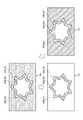
図9は、生成部131及び合成部43cの処理の一例を示す図である。
図9の左上図は、図2に示す信号処理部42から入力される入力画像PBの一例を示す。入力画像PBは、第1ペンギン画像PG1、第2ペンギン画像PG2及び第3ペンギン画像PG3を含む。
図9の左下図は、マスク画像MPSの一例としての第2マスク画像MP2を示す。生成部131は、図5に示す第2画像P2の各画素の輝度値Bを透過率Tに変換して第2マスク画像MP2を生成する。本実施形態では、生成部131は、輝度値Bが大きい程、透過率Tが大きくなるように、輝度値Bを透過率Tに変換する。
具体的には、生成部131は、第1輝度値B1を第1透過率T1に変換し、第2輝度値B2を第2透過率T2に変換し、第3輝度値B3を第3透過率T3に変換する。第1透過率T1は、第2透過率T2より大きく、第2透過率T2は、第3透過率T3より大きい。第1透過率T1は、例えば、透過率Tが100%であることを示し、第2透過率T2は、例えば、透過率Tが50%であることを示し、第3透過率T3は、例えば、透過率Tが0%であることを示す。
図9の左下図に示す第2マスク画像MP2は、第1領域AR1、第2領域SR2、及び、第3領域SR3を含む。第2マスク画像MP2において、第1領域AR1の透過率Tは、第1透過率T1であり、第2領域SR2の透過率Tは、第3透過率T3であり、第3領域SR3の透過率Tは、第1透過率T1である。[2-5. Processing of generator and synthesizer]
FIG. 9 is a diagram showing an example of processing of the
The upper left figure of FIG. 9 shows an example of the input image PB input from the
The lower left figure of FIG. 9 shows a second mask image MP2 as an example of the mask image MPS. The
Specifically, the
The second mask image MP2 shown in the lower left figure of FIG. 9 includes a first region AR1, a second region SR2, and a third region SR3. In the second mask image MP2, the transmittance T of the first region AR1 is the first transmittance T1, the transmittance T of the second region SR2 is the third transmittance T3, and the transmittance of the third region SR3. T is the first transmittance T1.
図9では、選択部132が、第2マスク画像MP2を選択する場合について説明する。
この場合には、合成部43cは、入力画像PBと第2マスク画像MP2とを重ねて合成し、合成画像PCを生成する。
図9の右図は、合成画像PCの一例を示す。第2マスク画像MP2において、第1領域AR1及び第3領域SR3の透過率Tは第1透過率T1であるため、第1領域AR1及び第3領域SR3においては、入力画像PBが視認される。これに対して、第2マスク画像MP2において、第2領域SR2の透過率Tは、第3透過率T3であるため、入力画像PBが視認できない。その結果、入力画像PBに含まれる第3ペンギン画像PG3は視認でき、入力画像PBに含まれる第1ペンギン画像PG1の一部と、第2ペンギン画像PG2の一部とが視認できない。FIG. 9 describes a case where the
In this case, the
The right figure of FIG. 9 shows an example of a composite image PC. In the second mask image MP2, since the transmittance T of the first region AR1 and the third region SR3 is the first transmittance T1, the input image PB is visually recognized in the first region AR1 and the third region SR3. On the other hand, in the second mask image MP2, the transmittance T of the second region SR2 is the third transmittance T3, so that the input image PB cannot be visually recognized. As a result, the third penguins image PG3 included in the input image PB can be visually recognized, and a part of the first penguins image PG1 included in the input image PB and a part of the second penguins image PG2 cannot be visually recognized.
図10は、生成部131及び合成部43cの処理の他の一例を示す図である。
図9では、選択部132が、第2マスク画像MP2を選択するのに対して、図10では、選択部132が、第3マスク画像MP3を選択する点で相違している。以下の説明では、図9と相違する点について主に説明する。
図10の左下図は、マスク画像MPSの一例としての第3マスク画像MP3を示す。生成部131は、第3画像P3の各画素の輝度値Bを透過率Tに変換して第3マスク画像MP3を生成する。
図10の左下図に示す第3マスク画像MP3は、第1領域AR1、第2領域SR2、及び、第3領域SR3を含む。第3マスク画像MP3において、第1領域AR1の透過率Tは、第2透過率T2であり、第2領域SR2の透過率Tは、第1透過率T1であり、第3領域SR3の透過率Tは、第3透過率T3である。FIG. 10 is a diagram showing another example of processing of the
In FIG. 9, the
The lower left figure of FIG. 10 shows a third mask image MP3 as an example of the mask image MPS. The
The third mask image MP3 shown in the lower left figure of FIG. 10 includes a first region AR1, a second region SR2, and a third region SR3. In the third mask image MP3, the transmittance T of the first region AR1 is the second transmittance T2, the transmittance T of the second region SR2 is the first transmittance T1, and the transmittance of the third region SR3. T is the third transmittance T3.
合成部43cは、入力画像PBと第3マスク画像MP3とを重ねて合成し、合成画像PCを生成する。
図10の右図は、合成画像PCの一例を示す。第3マスク画像MP3において、第2領域AR2の透過率Tは第1透過率T1であるため、第2領域AR2においては、入力画像PBが視認される。また、第1領域AR1の透過率Tは第2透過率T2であるため、入力画像PBが、第2領域AR2よりも暗く視認される。これに対して、第3マスク画像MP3において、第3領域SR3の透過率Tは、第3透過率T3であるため、入力画像PBが視認できない。その結果、入力画像PBに含まれる第1ペンギン画像PG1及び第2ペンギン画像PG2は視認できず、第3ペンギン画像PG3が暗く視認できる。The
The right figure of FIG. 10 shows an example of a composite image PC. In the third mask image MP3, since the transmittance T of the second region AR2 is the first transmittance T1, the input image PB is visually recognized in the second region AR2. Further, since the transmittance T of the first region AR1 is the second transmittance T2, the input image PB is visually recognized darker than the second region AR2. On the other hand, in the third mask image MP3, the transmittance T of the third region SR3 is the third transmittance T3, so that the input image PB cannot be visually recognized. As a result, the first penguins image PG1 and the second penguins image PG2 included in the input image PB cannot be visually recognized, and the third penguins image PG3 can be visually recognized darkly.
[3.制御部及び映像処理部の処理]
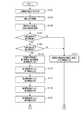
図11及び図12は、制御部10及び映像処理部40の処理の一例を示すフローチャートである。
図11に示すように、まず、ステップS101において、輝度調整部111が、元画像PAの輝度分布を取得する。具体的には、輝度調整部111は、第1輝度値BA1及び第3輝度値BA3を取得する。第1輝度値BA1は、元画像PAを構成する画素の輝度値BAのうち、最大の輝度値を示す。第3輝度値BA3は、元画像PAを構成する画素の輝度値BAのうち、最小の輝度値を示す。
次に、ステップS103において、輝度調整部111は、元画像PAの画素の第1輝度値BA1が最大輝度値BXになり、元画像PAの画素の第3輝度値BA3が最小輝度値BNになるように、元画像PAを構成する画素の輝度値BAを輝度値Bに調整する。[3. Processing of control unit and video processing unit]
11 and 12 are flowcharts showing an example of processing by the
As shown in FIG. 11, first, in step S101, the
Next, in step S103, in the
次に、ステップS105において、判定部112は、元画像PAの外縁を構成する画素の輝度値Bを取得する。
次に、ステップS107において、判定部112は、元画像PAの外縁を構成する画素の輝度値Bが、最大輝度値BXであるか否かを判定する。
元画像PAの外縁を構成する画素の輝度値Bが、最大輝度値BXであると判定部112が判定した場合(ステップS107;YES)には、処理がステップS111に進む。元画像PAの外縁を構成する画素の輝度値Bが、最大輝度値BXではないと判定部112が判定した場合(ステップS107;NO)には、処理がステップS109に進む。
そして、ステップS109において、判定部112は、元画像PAの外縁を構成する画素の輝度値Bが、最小輝度値BNであるか否かを判定する。
元画像PAの外縁を構成する画素の輝度値Bが最小輝度値BNであると判定部112が判定した場合(ステップS109;YES)には、処理がステップS111に進む。
そして、ステップS111において、生成部131は、元画像PAにおいて、各画素の輝度値Bを透過率Tに変換してマスク画像MPAを生成し、生成したマスク画像MPAをマスク記憶部151に記録する。その後、処理が図12のステップS135に進む。
元画像PAの外縁を構成する画素の輝度値Bが最小輝度値BNではないと判定部112が判定した場合(ステップS109;NO)には、処理がステップS113に進む。
そして、ステップS113において、区分部113は、元画像PAの各画素の輝度値Bを第1輝度値B1、第2輝度値B2、及び第3輝度値B3に区分する。第1輝度値B1は、最大輝度値BXであり、第3輝度値B3は、最小輝度値BNであり、第2輝度値B2は、中間諧調の輝度値Bを示す。Next, in step S105, the
Next, in step S107, the
When the
Then, in step S109, the
When the
Then, in step S111, the
When the
Then, in step S113, the
次に、ステップS115において、第1置換部121は、第1置換処理を実行して、第1画像P1を生成する。第1置換処理は、元画像PAにおいて、第2輝度値B2に対応する画素の輝度値Bを第3輝度値B3に置換する処理を示す。
次に、ステップS117において、第2置換部122は、第2置換処理を実行して、第2画像P2を生成する。第2置換処理は、元画像PAにおいて、第2輝度値B2に対応する画素の輝度値Bを第1輝度値B1に置換する処理を示す。
次に、ステップS119において、第3置換部123は、第3置換処理を実行して、第3画像P3を生成する。第3置換処理は、元画像PAにおいて、第2輝度値B2に対応する画素の輝度値Bを第3輝度値B3に置換すると共に、第3輝度値B3に対応する画素の輝度値Bを第2輝度値B2に置換する処理を示す。
次に、ステップS121において、第4置換部124は、第4置換処理を実行して、第4画像P4を生成する。第4置換処理は、元画像PAにおいて、第2輝度値B2に対応する画素の輝度値Bを第1輝度値B1に置換すると共に、第1輝度値B1に対応する画素の輝度値Bを第2輝度値B2に置換する処理を示す。Next, in step S115, the
Next, in step S117, the
Next, in step S119, the
Next, in step S121, the
次に、図12に示すように、ステップS123において、第5置換部125は、第5置換処理を実行して、第5画像P5を生成する。第5置換処理は、第1画像P1において、第3輝度値B3に対応する画素の輝度値Bを第1輝度値B1に置換すると共に、第1輝度値B1に対応する画素の輝度値Bを第3輝度値B3に置換する処理を示す。
次に、ステップS125において、第6置換部126は、第6置換処理を実行して、第6画像P6を生成する。第6置換処理は、第2画像P2において、第3輝度値B3に対応する画素の輝度値Bを第1輝度値B1に置換すると共に、第1輝度値B1に対応する画素の輝度値Bを第3輝度値B3に置換する処理を示す。
次に、ステップS127において、第7置換部127は、第7置換処理を実行して、第7画像P7を生成する。第7置換処理は、第3画像P3において、第3輝度値B3に対応する画素の輝度値Bを第1輝度値B1に置換すると共に、第1輝度値B1に対応する画素の輝度値Bを第3輝度値B3に置換する処理を示す。
次に、ステップS129において、第8置換部128は、第8置換処理を実行して、第8画像P8を生成する。第8置換処理は、第4画像P4において、第3輝度値B3に対応する画素の輝度値Bを第1輝度値B1に置換すると共に、第1輝度値B1に対応する画素の輝度値Bを第3輝度値B3に置換する処理を示す。Next, as shown in FIG. 12, in step S123, the
Next, in step S125, the
Next, in step S127, the
Next, in step S129, the
次に、ステップS131において、生成部131は、第1画像P1〜第8画像P8の各々に対して、各画素の輝度値Bを透過率Tに変換して第1マスク画像MP1〜第8マスク画像MP8を生成し、第1マスク画像MP1〜第8マスク画像MP8をマスク記憶部151に記録する。
次に、ステップS133において、選択部132は、ユーザーからの操作に基づいて、第1マスク画像MP1〜第8マスク画像MP8の中から1つのマスク画像MPSを選択する。
次に、ステップS135において、合成部43cは、信号処理部42から入力される入力画像PBに、マスク画像MPSを重ねて合成し、合成画像PCを生成する。
次に、ステップS137において、制御部10は、画像形成部20を介して、合成画像PCをスクリーンSCに投射する。
次に、ステップS139において、制御部10は、スクリーンSCへの合成画像PCの表示を終了するか否かを判定する。
スクリーンSCへの合成画像PCの表示を終了しないと制御部10が判定した場合(ステップS139;NO)には、処理がステップS135に戻る。スクリーンSCへの合成画像PCの表示を終了すると制御部10が判定した場合(ステップS139;YES)には、処理が終了する。Next, in step S131, the
Next, in step S133, the
Next, in step S135, the
Next, in step S137, the
Next, in step S139, the
When the
ステップS107及びステップS109は、「判定ステップ」の一例に対応する。ステップS113は、「区分ステップ」の一例に対応する。ステップS115は、「第1置換ステップ」の一例に対応する。ステップS117は、「第2置換ステップ」の一例に対応する。ステップS119は、「第3置換ステップ」の一例に対応する。ステップS121は、「第4置換ステップ」の一例に対応する。ステップS123は、「第5置換ステップ」の一例に対応する。ステップS125は、「第6置換ステップ」の一例に対応する。ステップS127は、「第7置換ステップ」の一例に対応する。ステップS129は、「第8置換ステップ」の一例に対応する。ステップS111及びステップS131は、「生成ステップ」の一例に対応する。 Step S107 and step S109 correspond to an example of the "determination step". Step S113 corresponds to an example of the “classification step”. Step S115 corresponds to an example of the “first replacement step”. Step S117 corresponds to an example of the “second replacement step”. Step S119 corresponds to an example of the "third replacement step". Step S121 corresponds to an example of the "fourth replacement step". Step S123 corresponds to an example of the "fifth replacement step". Step S125 corresponds to an example of the “sixth replacement step”. Step S127 corresponds to an example of the "seventh replacement step". Step S129 corresponds to an example of the "eighth replacement step". Step S111 and step S131 correspond to an example of the "generation step".
[4.本実施形態及び作用効果]
以上、図1〜図12を参照して説明したように、本実施形態に係るプロジェクター1の制御方法は、元画像PAを構成する複数の画素の輝度値Bの各々を、第1輝度値B1、第1輝度値B1より小さい第2輝度値B2、及び、第2輝度値B2より小さい第3輝度値B3に区分する区分ステップと、元画像PAにおいて、第2輝度値B2に対応する画素の輝度値Bを第3輝度値B3に置換して、第1画像P1を生成する第1置換ステップと、元画像PAにおいて、第2輝度値B2に対応する画素の輝度値Bを第1輝度値B1に置換して、第2画像P2を生成する第2置換ステップと、第1画像P1及び第2画像P2の各々において、各画素の輝度値Bを透過率Tに変換してマスク画像MPを生成する生成ステップと、を含む。
よって、元画像PAにおいて、第2輝度値B2に対応する画素の輝度値Bを第3輝度値B3に置換して第1画像P1を生成し、元画像PAにおいて、第2輝度値B2に対応する画素の輝度値Bを第1輝度値B1に置換して第2画像P2を生成するため、各画素の輝度値Bが第1輝度値B1及び第3輝度値B3で構成される第1画像P1及び第2画像P2を生成できる。また、第1画像P1及び第2画像P2の各々において、各画素の輝度値Bを透過率Tに変換してマスク画像MPを生成するため、各画素の透過率Tが第1輝度値B1に対応する第1透過率T1と、第3輝度値B3に対応する第3透過率T3とで構成されるマスク画像MPを生成できる。したがって、ユーザーの所望するマスク画像MPを生成する可能性を高めることができる。[4. This embodiment and action effect]
As described above with reference to FIGS. 1 to 12, in the control method of the projector 1 according to the present embodiment, each of the brightness values B of the plurality of pixels constituting the original image PA is set to the first brightness value B1. , A classification step for classifying into a second luminance value B2 smaller than the first luminance value B1 and a third luminance value B3 smaller than the second luminance value B2, and in the original image PA, the pixels corresponding to the second luminance value B2. In the first replacement step of replacing the luminance value B with the third luminance value B3 to generate the first image P1, and in the original image PA, the luminance value B of the pixel corresponding to the second luminance value B2 is the first luminance value. In the second replacement step of replacing with B1 to generate the second image P2, and in each of the first image P1 and the second image P2, the brightness value B of each pixel is converted into the transmission T and the mask image MP is generated. Includes a generation step to generate.
Therefore, in the original image PA, the brightness value B of the pixel corresponding to the second brightness value B2 is replaced with the third brightness value B3 to generate the first image P1, and the original image PA corresponds to the second brightness value B2. In order to generate the second image P2 by replacing the luminance value B of the pixels with the first luminance value B1, the first image in which the luminance value B of each pixel is composed of the first luminance value B1 and the third luminance value B3. P1 and the second image P2 can be generated. Further, in each of the first image P1 and the second image P2, the transmittance T of each pixel is set to the first luminance value B1 because the brightness value B of each pixel is converted into the transmittance T to generate the mask image MP. A mask image MP composed of the corresponding first transmittance T1 and the third transmittance T3 corresponding to the third luminance value B3 can be generated. Therefore, it is possible to increase the possibility of generating the mask image MP desired by the user.
また、元画像PAにおいて、第2輝度値B2に対応する画素の輝度値Bを第3輝度値B3に置換すると共に、第3輝度値B3に対応する画素の輝度値Bを第2輝度値B2に置換して、第3画像P3を生成する第3置換ステップと、元画像PAにおいて、第2輝度値B2に対応する画素の輝度値Bを第1輝度値B1に置換すると共に、第1輝度値B1に対応する画素の輝度値Bを第2輝度値B2に置換して、第4画像P4を生成する第4置換ステップと、を含み、生成ステップでは、第3画像P3及び第4画像P4の各々において、各画素の輝度値Bを透過率Tに変換してマスク画像MPを生成する。
よって、元画像PAにおいて、第2輝度値B2に対応する画素の輝度値Bを第3輝度値B3に置換すると共に、第3輝度値B3に対応する画素の輝度値Bを第2輝度値B2に置換して、第3画像P3を生成するため、例えば、元画像PAの外縁を含む領域の輝度値Bが第2輝度値B2である場合に、外縁を含む領域の輝度値Bが第3輝度値B3である第3画像P3を生成できる。また、元画像PAにおいて、第2輝度値B2に対応する画素の輝度値Bを第1輝度値B1に置換すると共に、第1輝度値B1に対応する画素の輝度値Bを第2輝度値B2に置換して、第4画像P4を生成するため、例えば、元画像PAの外縁を含む領域の輝度値Bが第2輝度値B2である場合に、外縁を含む領域の輝度値Bが第1輝度値B1である第4画像P4を生成できる。また、第3画像P3及び第4画像P4の各々において、各画素の輝度値Bを透過率Tに変換してマスク画像MPを生成するため、外縁を含む領域の透過率Tが、第1輝度値B1に対応する第1透過率T1又は第3輝度値B3に対応する第3透過率T3であるマスク画像MPを生成できる。したがって、ユーザーの所望するマスク画像MPを生成する可能性を更に高めることができる。Further, in the original image PA, the brightness value B of the pixel corresponding to the second brightness value B2 is replaced with the third brightness value B3, and the brightness value B of the pixel corresponding to the third brightness value B3 is replaced with the second brightness value B2. In the third replacement step of generating the third image P3 by replacing with, and in the original image PA, the brightness value B of the pixel corresponding to the second brightness value B2 is replaced with the first brightness value B1 and the first brightness. A fourth replacement step of replacing the brightness value B of the pixel corresponding to the value B1 with the second brightness value B2 to generate the fourth image P4 is included, and the generation step includes the third image P3 and the fourth image P4. In each of the above, the brightness value B of each pixel is converted into the transmission rate T to generate a mask image MP.
Therefore, in the original image PA, the brightness value B of the pixel corresponding to the second brightness value B2 is replaced with the third brightness value B3, and the brightness value B of the pixel corresponding to the third brightness value B3 is replaced with the second brightness value B2. To generate the third image P3, for example, when the luminance value B of the region including the outer edge of the original image PA is the second luminance value B2, the luminance value B of the region including the outer edge is the third. The third image P3 having the luminance value B3 can be generated. Further, in the original image PA, the brightness value B of the pixel corresponding to the second brightness value B2 is replaced with the first brightness value B1, and the brightness value B of the pixel corresponding to the first brightness value B1 is replaced with the second brightness value B2. In order to generate the fourth image P4 by replacing with, for example, when the luminance value B of the region including the outer edge of the original image PA is the second luminance value B2, the luminance value B of the region including the outer edge is the first. The fourth image P4 having the luminance value B1 can be generated. Further, in each of the third image P3 and the fourth image P4, since the brightness value B of each pixel is converted into the transmittance T to generate the mask image MP, the transmittance T of the region including the outer edge is the first brightness. A mask image MP having a first transmittance T1 corresponding to the value B1 or a third transmittance T3 corresponding to the third luminance value B3 can be generated. Therefore, the possibility of generating the mask image MP desired by the user can be further increased.
また、第1画像P1において、第3輝度値B3に対応する画素の輝度値Bを第1輝度値B1に置換すると共に、第1輝度値B1に対応する画素の輝度値Bを第3輝度値B3に置換して、第5画像P5を生成する第5置換ステップと、第2画像P2において、第3輝度値B3に対応する画素の輝度値Bを第1輝度値B1に置換すると共に、第1輝度値B1に対応する画素の輝度値Bを第3輝度値B3に置換して、第6画像P6を生成する第6置換ステップと、を含み、生成ステップでは、第5画像P5、及び第6画像P6の各々において、各画素の輝度値Bを透過率Tに変換してマスク画像MPを生成する。
よって、第1画像P1において、第3輝度値B3に対応する画素の輝度値Bを第1輝度値B1に置換すると共に、第1輝度値B1に対応する画素の輝度値Bを第3輝度値B3に置換して、第5画像P5を生成し、第2画像P2において、第3輝度値B3に対応する画素の輝度値Bを第1輝度値B1に置換すると共に、第1輝度値B1に対応する画素の輝度値Bを第3輝度値B3に置換して、第6画像P6を生成するため、各画素の輝度値Bが第1輝度値B1及び第3輝度値B3で構成される第5画像P5及び第6画像P6を生成できる。また、第5画像P5及び第6画像P6の各々において、各画素の輝度値Bを透過率Tに変換してマスク画像MPを生成するため、各画素の透過率Tが第1輝度値B1に対応する第1透過率T1と、第3輝度値B3に対応する第3透過率T3とで構成されるマスク画像MPを生成できる。したがって、ユーザーの所望するマスク画像MPを生成する可能性を高めることができる。Further, in the first image P1, the brightness value B of the pixel corresponding to the third brightness value B3 is replaced with the first brightness value B1, and the brightness value B of the pixel corresponding to the first brightness value B1 is replaced with the third brightness value. In the fifth replacement step of replacing with B3 to generate the fifth image P5 and in the second image P2, the brightness value B of the pixel corresponding to the third brightness value B3 is replaced with the first brightness value B1 and the first brightness value B1 is used. The sixth substitution step of replacing the luminance value B of the pixel corresponding to the first luminance value B1 with the third luminance value B3 to generate the sixth image P6 is included, and the generation step includes the fifth image P5 and the third image P6. In each of the 6 images P6, the luminance value B of each pixel is converted into the transmission rate T to generate the mask image MP.
Therefore, in the first image P1, the brightness value B of the pixel corresponding to the third brightness value B3 is replaced with the first brightness value B1, and the brightness value B of the pixel corresponding to the first brightness value B1 is replaced with the third brightness value. The fifth image P5 is generated by replacing with B3, and in the second image P2, the brightness value B of the pixel corresponding to the third brightness value B3 is replaced with the first brightness value B1 and the first brightness value B1. Since the brightness value B of the corresponding pixel is replaced with the third brightness value B3 to generate the sixth image P6, the brightness value B of each pixel is composed of the first brightness value B1 and the third brightness value B3. The 5th image P5 and the 6th image P6 can be generated. Further, in each of the fifth image P5 and the sixth image P6, the transmittance T of each pixel is set to the first luminance value B1 because the brightness value B of each pixel is converted into the transmittance T to generate the mask image MP. A mask image MP composed of the corresponding first transmittance T1 and the third transmittance T3 corresponding to the third luminance value B3 can be generated. Therefore, it is possible to increase the possibility of generating the mask image MP desired by the user.
また、第3画像P3において、第3輝度値B3に対応する画素の輝度値Bを第1輝度値B1に置換すると共に、第1輝度値B1に対応する画素の輝度値Bを第3輝度値B3に置換して、第7画像P7を生成する第7置換ステップと、第4画像P4において、第3輝度値B3に対応する画素の輝度値Bを第1輝度値B1に置換すると共に、第1輝度値B1に対応する画素の輝度値Bを第3輝度値B3に置換して、第8画像P8を生成する第8置換ステップと、を含み、生成ステップでは、第7画像P7、及び第8画像P8の各々において、各画素の輝度値Bを透過率Tに変換して、マスク画像MPを生成する。
したがって、第3画像P3において、第3輝度値B3に対応する画素の輝度値Bを第1輝度値B1に置換すると共に、第1輝度値B1に対応する画素の輝度値Bを第3輝度値B3に置換して、第7画像P7を生成するため、例えば、元画像PAの外縁を含む領域の輝度値Bが第2輝度値B2である場合に、外縁を含む領域の輝度値Bが第1輝度値B1である第7画像P7を生成できる。また、第4画像P4において、第3輝度値B3に対応する画素の輝度値Bを第1輝度値B1に置換すると共に、第1輝度値B1に対応する画素の輝度値Bを第3輝度値B3に置換して、第8画像P8を生成するため、例えば、元画像PAの外縁を含む領域の輝度値Bが第2輝度値B2である場合に、外縁を含む領域の輝度値Bが第3輝度値B3である第8画像P8を生成できる。また、第7画像P7及び第8画像P8の各々において、各画素の輝度値Bを透過率Tに変換してマスク画像MPを生成するため、外縁を含む領域の透過率Tが、第1輝度値B1に対応する第1透過率T1又は第3輝度値B3に対応する第3透過率T3であるマスク画像MPを生成できる。したがって、ユーザーの所望するマスク画像MPを生成する可能性を更に高めことができる。Further, in the third image P3, the brightness value B of the pixel corresponding to the third brightness value B3 is replaced with the first brightness value B1, and the brightness value B of the pixel corresponding to the first brightness value B1 is replaced with the third brightness value. In the seventh replacement step of replacing with B3 to generate the seventh image P7 and in the fourth image P4, the luminance value B of the pixel corresponding to the third luminance value B3 is replaced with the first luminance value B1 and the first luminance value B1 is used. The eighth substitution step of replacing the luminance value B of the pixel corresponding to the first luminance value B1 with the third luminance value B3 to generate the eighth image P8 is included, and the generation step includes the seventh image P7 and the third image P8. In each of the eight images P8, the luminance value B of each pixel is converted into a transmission T, and a mask image MP is generated.
Therefore, in the third image P3, the brightness value B of the pixel corresponding to the third brightness value B3 is replaced with the first brightness value B1, and the brightness value B of the pixel corresponding to the first brightness value B1 is replaced with the third brightness value. In order to generate the seventh image P7 by substituting with B3, for example, when the luminance value B of the region including the outer edge of the original image PA is the second luminance value B2, the luminance value B of the region including the outer edge is the second. The seventh image P7 having one luminance value B1 can be generated. Further, in the fourth image P4, the brightness value B of the pixel corresponding to the third brightness value B3 is replaced with the first brightness value B1, and the brightness value B of the pixel corresponding to the first brightness value B1 is replaced with the third brightness value. Since the eighth image P8 is generated by replacing with B3, for example, when the luminance value B of the region including the outer edge of the original image PA is the second luminance value B2, the luminance value B of the region including the outer edge is the second. The eighth image P8 having the three luminance values B3 can be generated. Further, in each of the 7th image P7 and the 8th image P8, since the brightness value B of each pixel is converted into the transmittance T to generate the mask image MP, the transmittance T of the region including the outer edge is the first brightness. A mask image MP having a first transmittance T1 corresponding to the value B1 or a third transmittance T3 corresponding to the third luminance value B3 can be generated. Therefore, the possibility of generating the mask image MP desired by the user can be further increased.
また、第1輝度値B1、最大輝度値BXを示し、第3輝度値B3は、最小輝度値BNを示す。
また、例えば、第1画像P1及び第2画像P2の各々において、各画素の輝度値Bを透過率Tに変換してマスク画像MPを生成する。よって、各画素の透過率Tが最大輝度値BXに対応する透過率Tと、最小輝度値BNに対応する透過率Tとで構成されるマスク画像MPを生成できる。したがって、ユーザーの所望するマスク画像を生成する可能性を高めることができる。Further, the first luminance value B1 and the maximum luminance value BX are shown, and the third luminance value B3 shows the minimum luminance value BN.
Further, for example, in each of the first image P1 and the second image P2, the brightness value B of each pixel is converted into the transmittance T to generate the mask image MP. Therefore, it is possible to generate a mask image MP in which the transmittance T of each pixel corresponds to the maximum luminance value BX and the transmittance T corresponds to the minimum luminance value BN. Therefore, it is possible to increase the possibility of generating the mask image desired by the user.
また、元画像PAの外縁を構成する画素の輝度値Bが、第2輝度値B2であるか否かを判定する判定ステップを含み、判定ステップにおいて、元画像PAの外縁を構成する画素の輝度値Bが第2輝度値B2ではないと判定された場合に、生成ステップでは、元画像PAにおいて、各画素の輝度値Bを透過率Tに変換してマスク画像MPを生成する。
よって、元画像PAの外縁を構成する画素の輝度値Bが、第2輝度値B2ではないと判定された場合、すなわち、元画像PAの外縁を構成する画素の輝度値Bが、第1輝度値B1又は第3輝度値B3である場合に、元画像PAにおいて、各画素の輝度値Bを透過率Tに変換してマスク画像MPを生成する。したがって、外縁を含む領域の透過率Tが、第1輝度値B1に対応する第1透過率T1又は第3輝度値B3に対応する第3透過率T3であるマスク画像MPを生成できる。その結果、ユーザーの所望するマスク画像MPを生成する可能性を高めることができる。Further, a determination step of determining whether or not the luminance value B of the pixels constituting the outer edge of the original image PA is the second luminance value B2 is included, and in the determination step, the luminance of the pixels constituting the outer edge of the original image PA is included. When it is determined that the value B is not the second luminance value B2, in the generation step, the luminance value B of each pixel is converted into the transmittance T in the original image PA to generate the mask image MP.
Therefore, when it is determined that the luminance value B of the pixels constituting the outer edge of the original image PA is not the second luminance value B2, that is, the luminance value B of the pixels constituting the outer edge of the original image PA is the first luminance. When the value is B1 or the third luminance value B3, the luminance value B of each pixel is converted into the transmittance T in the original image PA to generate the mask image MP. Therefore, it is possible to generate a mask image MP in which the transmittance T of the region including the outer edge is the first transmittance T1 corresponding to the first luminance value B1 or the third transmittance T3 corresponding to the third luminance value B3. As a result, the possibility of generating the mask image MP desired by the user can be increased.
また、プロジェクター1は、元画像PAを構成する複数の画素の輝度値Bの各々を、第1輝度値B1、第1輝度値B1より小さい第2輝度値B2、及び、第2輝度値B2より小さい第3輝度値B3に区分する区分部113と、元画像PAにおいて、第2輝度値B2に対応する画素の輝度値Bを第3輝度値B3に置換して第1画像P1を生成する第1置換部121と、元画像PAにおいて、第2輝度値B2に対応する画素の輝度値Bを第1輝度値B1に置換して第2画像P2を生成する第2置換部122と、第1画像P1及び第2画像P2の各々において、各画素の輝度値Bを透過率Tに変換してマスク画像MPを生成する生成部131と、を備える。
よって、元画像PAにおいて、第2輝度値B2に対応する画素の輝度値Bを第3輝度値B3に置換して、第1画像P1を生成し、元画像PAにおいて、第2輝度値B2に対応する画素の輝度値Bを第1輝度値B1に置換して、第2画像P2を生成するため、各画素の輝度値Bが第1輝度値B1及び第3輝度値B3で構成される第1画像P1及び第2画像P2を生成できる。また、第1画像P1及び第2画像P2の各々において、各画素の輝度値Bを透過率Tに変換してマスク画像MPを生成するため、各画素の透過率Tが第1輝度値B1に対応する第1透過率T1と、第3輝度値B3に対応する第3透過率T3とで構成されるマスク画像MPを生成できる。したがって、ユーザーの所望するマスク画像MPを生成する可能性を高めることができる。Further, the projector 1 sets each of the brightness values B of the plurality of pixels constituting the original image PA from the first brightness value B1, the second brightness value B2 smaller than the first brightness value B1, and the second brightness value B2. A third image P1 is generated by substituting the luminance value B of the pixel corresponding to the second luminance value B2 with the third luminance value B3 in the
Therefore, in the original image PA, the brightness value B of the pixel corresponding to the second brightness value B2 is replaced with the third brightness value B3 to generate the first image P1, and in the original image PA, the second brightness value B2 is used. Since the brightness value B of the corresponding pixel is replaced with the first brightness value B1 to generate the second image P2, the brightness value B of each pixel is composed of the first brightness value B1 and the third brightness value B3. One image P1 and a second image P2 can be generated. Further, in each of the first image P1 and the second image P2, the transmittance T of each pixel is set to the first luminance value B1 because the brightness value B of each pixel is converted into the transmittance T to generate the mask image MP. A mask image MP composed of the corresponding first transmittance T1 and the third transmittance T3 corresponding to the third luminance value B3 can be generated. Therefore, it is possible to increase the possibility of generating the mask image MP desired by the user.
[5.他の実施形態]
上述した本実施形態は、好適な実施の形態である。ただし、上述の実施形態に限定されるものではなく、要旨を逸脱しない範囲内において種々の変形実施が可能である。
本実施形態では、「表示装置」がプロジェクター1であるが、本発明の実施形態はこれに限定されない。「表示装置」がマスク画像MPと入力画像PBとを合成した合成画像PCを生成、合成画像PCを表示すればよい。「表示装置」が、例えば、LCD(Liquid Crystal Display)等で構成されてもよい。[5. Other embodiments]
The above-described embodiment is a preferred embodiment. However, the present invention is not limited to the above-described embodiment, and various modifications can be carried out within a range that does not deviate from the gist.
In the present embodiment, the "display device" is the projector 1, but the embodiment of the present invention is not limited to this. The "display device" may generate a composite image PC in which the mask image MP and the input image PB are combined, and display the composite image PC. The "display device" may be configured by, for example, an LCD (Liquid Crystal Display) or the like.
本実施形態では、元画像PAの画素の第1輝度値BA1が最大輝度値BXになり、元画像PAの画素の第3輝度値BA3が最小輝度値BNになるように、輝度調整部111が元画像PAの画素の輝度値BAを調整した後、第1画像P1〜第8画像P8の各々を生成するが、本発明の実施形態はこれに限定されない。輝度調整部111が元画像PAの画素の輝度値BAを調整せずに、第1画像P1〜第8画像P8の各々を生成してもよい。この場合には、処理が簡素化できる。 In the present embodiment, the
また、本実施形態では、元画像PAに基づき、第1画像P1〜第8画像P8の各々を生成するが、本発明の実施形態はこれに限定されない。元画像PAに基づき、少なくとも第1画像P1及び第2画像P2を生成すればよい。元画像PAに基づき、例えば、第1画像P1〜第4画像P4の各々を生成してもよい。また、元画像PAに基づき、第1画像P1、第2画像P2、第5画像P5及び第6画像P6の各々を生成してもよい。 Further, in the present embodiment, each of the first image P1 to the eighth image P8 is generated based on the original image PA, but the embodiment of the present invention is not limited to this. At least the first image P1 and the second image P2 may be generated based on the original image PA. For example, each of the first image P1 to the fourth image P4 may be generated based on the original image PA. Further, each of the first image P1, the second image P2, the fifth image P5, and the sixth image P6 may be generated based on the original image PA.
また、本実施形態では、生成部131は、輝度値Bが大きい程、透過率Tが大きくなるように、輝度値Bを透過率Tに変換するが、本発明の実施形態はこれに限定されない。生成部131は、輝度値Bを透過率Tに変換すればよい。生成部131は、例えば、輝度値Bが大きい程、透過率Tが小さくなるように、輝度値Bを透過率Tに変換してもよい。 Further, in the present embodiment, the
また、図1及び図2に示した各機能部は機能的構成を示すものであって、具体的な実装形態は特に制限されない。つまり、必ずしも各機能部に個別に対応するハードウェアが実装される必要はなく、一つのプロセッサーがプログラムを実行することで複数の機能部の機能を実現する構成とすることも勿論可能である。また、上記実施形態においてソフトウェアで実現される機能の一部をハードウェアで実現してもよく、或いは、ハードウェアで実現される機能の一部をソフトウェアで実現してもよい。その他、プロジェクター1の他の各部の具体的な細部構成についても、趣旨を逸脱しない範囲で任意に変更可能である。 Further, each functional unit shown in FIGS. 1 and 2 shows a functional configuration, and a specific mounting form is not particularly limited. That is, it is not always necessary to implement hardware corresponding to each functional unit individually, and it is of course possible to realize a configuration in which the functions of a plurality of functional units are realized by executing a program by one processor. Further, a part of the functions realized by the software in the above embodiment may be realized by the hardware, or a part of the functions realized by the hardware may be realized by the software. In addition, the specific detailed configuration of each of the other parts of the projector 1 can be arbitrarily changed without departing from the spirit.
また、図11及び図12に示すフローチャートの処理単位は、プロジェクター1の処理を理解容易にするために、主な処理内容に応じて分割したものである。図11及び図12のフローチャートに示す処理単位の分割の仕方や名称によって制限されることはなく、処理内容に応じて、更に多くの処理単位に分割することもできるし、1つの処理単位が更に多くの処理を含むように分割することもできる。また、上記のフローチャートの処理順序も、図示した例に限られるものではない。 Further, the processing units of the flowcharts shown in FIGS. 11 and 12 are divided according to the main processing contents in order to make the processing of the projector 1 easy to understand. It is not limited by the method and name of division of the processing unit shown in the flowcharts of FIGS. 11 and 12, and can be further divided into more processing units according to the processing content, and one processing unit is further divided. It can also be divided to include many processes. Further, the processing order of the above flowchart is not limited to the illustrated example.
また、プロジェクター1の制御方法は、プロジェクター1が備えるプロセッサー10Aに、プロジェクター1の制御方法に対応したプログラムを実行させることで実現できる。また、このプログラムは、コンピューターで読み取り可能に記録した記録媒体に記録しておくことも可能である。記録媒体としては、磁気的、光学的記録媒体又は半導体メモリーデバイスを用いることができる。具体的には、フレキシブルディスク、HDD(Hard Disk Drive)、CD−ROM(Compact Disk Read Only Memory)、DVD(Digital Versatile Disk)、Blu−ray(登録商標) Disc、光磁気ディスク、フラッシュメモリー、カード型記録媒体等の可搬型、或いは固定式の記録媒体が挙げられる。また、記録媒体は、画像処理装置が備える内部記憶装置であるRAM(Random Access Memory)、ROM(Read Only Memory)、HDD等の不揮発性記憶装置であってもよい。また、プロジェクター1の制御方法に対応したプログラムをサーバー装置等に記憶させておき、サーバー装置からプロジェクター1に、プログラムをダウンロードすることでプロジェクター1の制御方法を実現することもできる。 Further, the control method of the projector 1 can be realized by causing the processor 10A included in the projector 1 to execute a program corresponding to the control method of the projector 1. The program can also be recorded on a computer-readable recording medium. As the recording medium, a magnetic or optical recording medium or a semiconductor memory device can be used. Specifically, flexible disks, HDDs (Hard Disk Drives), CD-ROMs (Compact Disk Read Only Memory), DVDs (Digital Versailles Disk), Blu-ray (registered trademark) Discs, optical magnetic disks, flash memories, cards. Examples include portable recording media such as type recording media, and fixed recording media. Further, the recording medium may be a non-volatile storage device such as a RAM (Random Access Memory), a ROM (Read Only Memory), or an HDD, which is an internal storage device included in the image processing device. It is also possible to realize the control method of the projector 1 by storing a program corresponding to the control method of the projector 1 in a server device or the like and downloading the program from the server device to the projector 1.
1…プロジェクター(表示装置)、2…映像供給装置、3…データ出力装置、4…記憶媒体、10…制御部、10A…プロセッサー、10B…メモリー、11…記憶部、20…画像形成部、21…光源、22…光変調装置、23…投射光学系、25…投射部、27…光源制御部、28…光変調装置駆動部、31…操作部、32…媒体読取部、33…I/F部、34…映像I/F部、40…映像処理部、41…映像信号入力部、42…信号処理部、43…OSD生成部、43a…形状調整部、43c…合成部、44…映像補正部、45…データ入力部、46…映像デコード部、47…画像入力部、48…画像メモリー、111…輝度調整部、112…判定部、113…区分部、121…第1置換部、122…第2置換部、123…第3置換部、124…第4置換部、125…第5置換部、126…第6置換部、127…第7置換部、128…第8置換部、131…生成部、132…選択部、151…マスク記憶部、AR1…第1領域、AR2…第2領域、B、BA…輝度値、B1…第1輝度値、B2…第2輝度値、B3…第3輝度値、BA1…第1輝度値、BA3…第3輝度値、BN…最小輝度値、BX…最大輝度値、MP、MPA、MPS…マスク画像、MP1…第1マスク画像、MP2…第2マスク画像、MP3…第3マスク画像、MP4…第4マスク画像、MP5…第5マスク画像、MP6…第6マスク画像、MP7…第7マスク画像、MP8…第8マスク画像、P1…第1画像、P2…第2画像、P3…第3画像、P4…第4画像、P5…第5画像、P6…第6画像、P7…第7画像、P8…第8画像、PB…入力画像、PC…合成画像、PP…投射画像、SC…スクリーン、SR1…第1領域、SR2…第2領域、SR3…第3領域、T…透過率、T1…第1透過率、T2…第2透過率、T3…第3透過率。 1 ... Projector (display device), 2 ... Video supply device, 3 ... Data output device, 4 ... Storage medium, 10 ... Control unit, 10A ... Processor, 10B ... Memory, 11 ... Storage unit, 20 ... Image forming unit, 21 ... light source, 22 ... optical modulator, 23 ... projection optical system, 25 ... projection unit, 27 ... light source control unit, 28 ... optical modulator drive unit, 31 ... operation unit, 32 ... medium reader, 33 ... I / F Unit, 34 ... Image I / F unit, 40 ... Image processing unit, 41 ... Video signal input unit, 42 ... Signal processing unit, 43 ... OSD generation unit, 43a ... Shape adjustment unit, 43c ... Synthesis unit, 44 ... Image correction Unit, 45 ... Data input unit, 46 ... Video decoding unit, 47 ... Image input unit, 48 ... Image memory, 111 ... Brightness adjustment unit, 112 ... Judgment unit, 113 ... Division unit, 121 ... First replacement unit, 122 ... 2nd replacement part, 123 ... 3rd replacement part, 124 ... 4th replacement part, 125 ... 5th replacement part, 126 ... 6th replacement part, 127 ... 7th replacement part, 128 ... 8th replacement part, 131 ... Generation Unit, 132 ... Selection unit, 151 ... Mask storage unit, AR1 ... First area, AR2 ... Second area, B, BA ... Brightness value, B1 ... First brightness value, B2 ... Second brightness value, B3 ... Third Brightness value, BA1 ... 1st brightness value, BA3 ... 3rd brightness value, BN ... Minimum brightness value, BX ... Maximum brightness value, MP, MPA, MPS ... Mask image, MP1 ... 1st mask image, MP2 ... 2nd mask Image, MP3 ... 3rd mask image, MP4 ... 4th mask image, MP5 ... 5th mask image, MP6 ... 6th mask image, MP7 ... 7th mask image, MP8 ... 8th mask image, P1 ... 1st image, P2 ... 2nd image, P3 ... 3rd image, P4 ... 4th image, P5 ... 5th image, P6 ... 6th image, P7 ... 7th image, P8 ... 8th image, PB ... Input image, PC ... Composite Image, PP ... Projected image, SC ... Screen, SR1 ... 1st region, SR2 ... 2nd region, SR3 ... 3rd region, T ... Transmission, T1 ... 1st transmission, T2 ... Second transmission, T3 ... Third transmission rate.
Claims (7)
Translated fromJapanese前記元画像において、前記第2輝度値に対応する画素の輝度値を前記第3輝度値に置換して第1画像を生成する第1置換ステップと、
前記元画像において、前記第2輝度値に対応する画素の輝度値を前記第1輝度値に置換して第2画像を生成する第2置換ステップと、
前記第1画像及び前記第2画像の各々において、各画素の輝度値を透過率に変換してマスク画像を生成する生成ステップと、
を含む、表示装置の制御方法。A division step of classifying each of the brightness values of a plurality of pixels constituting the original image into a first brightness value, a second brightness value smaller than the first brightness value, and a third brightness value smaller than the second brightness value. When,
In the original image, the first replacement step of replacing the brightness value of the pixel corresponding to the second brightness value with the third brightness value to generate the first image,
In the original image, a second replacement step of replacing the brightness value of the pixel corresponding to the second brightness value with the first brightness value to generate a second image,
In each of the first image and the second image, a generation step of converting the luminance value of each pixel into a transmittance to generate a mask image, and
Display device control methods, including.
前記元画像において、前記第2輝度値に対応する画素の輝度値を前記第1輝度値に置換すると共に、前記第1輝度値に対応する画素の輝度値を前記第2輝度値に置換して、第4画像を生成する第4置換ステップと、
を含み、
前記生成ステップでは、前記第3画像及び前記第4画像の各々において、各画素の輝度値を透過率に変換してマスク画像を生成する、請求項1に記載の表示装置の制御方法。In the original image, the brightness value of the pixel corresponding to the second brightness value is replaced with the third brightness value, and the brightness value of the pixel corresponding to the third brightness value is replaced with the second brightness value. , The third replacement step to generate the third image,
In the original image, the brightness value of the pixel corresponding to the second brightness value is replaced with the first brightness value, and the brightness value of the pixel corresponding to the first brightness value is replaced with the second brightness value. , The fourth replacement step to generate the fourth image, and
Including
The control method for a display device according to claim 1, wherein in the generation step, a mask image is generated by converting the luminance value of each pixel into a transmittance in each of the third image and the fourth image.
前記第2画像において、前記第3輝度値に対応する画素の輝度値を前記第1輝度値に置換すると共に、前記第1輝度値に対応する画素の輝度値を前記第3輝度値に置換して、第6画像を生成する第6置換ステップと、
を含み、
前記生成ステップでは、前記第5画像、及び前記第6画像の各々において、各画素の輝度値を透過率に変換してマスク画像を生成する、請求項1又は請求項2に記載の表示装置の制御方法。In the first image, the brightness value of the pixel corresponding to the third brightness value is replaced with the first brightness value, and the brightness value of the pixel corresponding to the first brightness value is replaced with the third brightness value. And the fifth replacement step to generate the fifth image,
In the second image, the brightness value of the pixel corresponding to the third brightness value is replaced with the first brightness value, and the brightness value of the pixel corresponding to the first brightness value is replaced with the third brightness value. And the sixth replacement step to generate the sixth image,
Including
The display device according to claim 1 or 2, wherein in the generation step, a mask image is generated by converting the luminance value of each pixel into a transmittance in each of the fifth image and the sixth image. Control method.
前記第4画像において、前記第3輝度値に対応する画素の輝度値を前記第1輝度値に置換すると共に、前記第1輝度値に対応する画素の輝度値を前記第3輝度値に置換して、第8画像を生成する第8置換ステップと、
を含み、
前記生成ステップでは、前記第7画像、及び前記第8画像の各々において、各画素の輝度値を透過率に変換してマスク画像を生成する、請求項2に記載の表示装置の制御方法。In the third image, the brightness value of the pixel corresponding to the third brightness value is replaced with the first brightness value, and the brightness value of the pixel corresponding to the first brightness value is replaced with the third brightness value. And the 7th replacement step to generate the 7th image,
In the fourth image, the brightness value of the pixel corresponding to the third brightness value is replaced with the first brightness value, and the brightness value of the pixel corresponding to the first brightness value is replaced with the third brightness value. And the 8th replacement step to generate the 8th image,
Including
The control method for a display device according to claim 2, wherein in the generation step, a mask image is generated by converting the luminance value of each pixel into a transmittance in each of the seventh image and the eighth image.
前記判定ステップにおいて、前記元画像の外縁を構成する画素の輝度値が前記第2輝度値ではないと判定された場合に、前記生成ステップでは、前記元画像において、各画素の輝度値を透過率に変換してマスク画像を生成する、請求項1から請求項5のいずれか1項に記載の表示装置の制御方法。A determination step for determining whether or not the brightness value of the pixels constituting the outer edge of the original image is the second brightness value is included.
When it is determined in the determination step that the luminance value of the pixels constituting the outer edge of the original image is not the second luminance value, in the generation step, the luminance value of each pixel is transmitted through the original image. The control method of the display device according to any one of claims 1 to 5, wherein a mask image is generated by converting to.
前記元画像において、前記第2輝度値に対応する画素の輝度値を前記第3輝度値に置換して第1画像を生成する第1置換部と、
前記元画像において、前記第2輝度値に対応する画素の輝度値を前記第1輝度値に置換して第2画像を生成する第2置換部と、
前記第1画像及び前記第2画像の各々において、各画素の輝度値を透過率に変換してマスク画像を生成する生成部と、
を備える、表示装置。A division unit that divides each of the brightness values of a plurality of pixels constituting the original image into a first brightness value, a second brightness value smaller than the first brightness value, and a third brightness value smaller than the second brightness value. When,
In the original image, a first replacement unit that generates a first image by replacing the brightness value of the pixel corresponding to the second brightness value with the third brightness value.
In the original image, a second replacement unit that generates a second image by replacing the brightness value of the pixel corresponding to the second brightness value with the first brightness value.
In each of the first image and the second image, a generation unit that converts the luminance value of each pixel into a transmittance to generate a mask image, and
A display device.
Priority Applications (4)
| Application Number | Priority Date | Filing Date | Title |
|---|---|---|---|
| JP2019234454AJP7276120B2 (en) | 2019-12-25 | 2019-12-25 | Display device control method and display device |
| US17/132,035US11064171B1 (en) | 2019-12-25 | 2020-12-23 | Method of controlling display device, and display device |
| CN202011534563.0ACN113035150B (en) | 2019-12-25 | 2020-12-23 | Display device control method and display device |
| EP20216912.4AEP3843078A1 (en) | 2019-12-25 | 2020-12-23 | Method of controlling display device, and display device |
Applications Claiming Priority (1)
| Application Number | Priority Date | Filing Date | Title |
|---|---|---|---|
| JP2019234454AJP7276120B2 (en) | 2019-12-25 | 2019-12-25 | Display device control method and display device |
Publications (3)
| Publication Number | Publication Date |
|---|---|
| JP2021103848Atrue JP2021103848A (en) | 2021-07-15 |
| JP2021103848A5 JP2021103848A5 (en) | 2022-08-04 |
| JP7276120B2 JP7276120B2 (en) | 2023-05-18 |
Family
ID=73857050
Family Applications (1)
| Application Number | Title | Priority Date | Filing Date |
|---|---|---|---|
| JP2019234454AActiveJP7276120B2 (en) | 2019-12-25 | 2019-12-25 | Display device control method and display device |
Country Status (4)
| Country | Link |
|---|---|
| US (1) | US11064171B1 (en) |
| EP (1) | EP3843078A1 (en) |
| JP (1) | JP7276120B2 (en) |
| CN (1) | CN113035150B (en) |
Citations (5)
| Publication number | Priority date | Publication date | Assignee | Title |
|---|---|---|---|---|
| JP2006071681A (en)* | 2004-08-31 | 2006-03-16 | Seiko Epson Corp | Image display system, light projection display device, display data processing device, light projection display device control program, display data processing device control program, light projection display device control method, and display data processing device control method |
| US20080266321A1 (en)* | 2007-04-30 | 2008-10-30 | Richard Aufranc | System and method for masking and overlaying images in multiple projector system |
| WO2010137496A1 (en)* | 2009-05-26 | 2010-12-02 | パナソニック電工株式会社 | Information presentation device |
| JP2013003990A (en)* | 2011-06-21 | 2013-01-07 | Casio Comput Co Ltd | Image processing device, image processing method, and program |
| US20190043444A1 (en)* | 2017-08-07 | 2019-02-07 | Seiko Epson Corporation | Display device and control method for display device |
Family Cites Families (11)
| Publication number | Priority date | Publication date | Assignee | Title |
|---|---|---|---|---|
| US5270688A (en)* | 1990-12-12 | 1993-12-14 | Apple Computer, Inc. | Apparatus for generating a cursor or other overlay which contrasts with the background on a computer output display |
| JPH06339150A (en) | 1993-05-31 | 1994-12-06 | Fuji Color Service:Kk | Compositing method of shade in electronic picture |
| JP4957128B2 (en) | 2006-09-04 | 2012-06-20 | セイコーエプソン株式会社 | Multi-projection system |
| JP5053215B2 (en) | 2008-09-17 | 2012-10-17 | 大日本スクリーン製造株式会社 | Image processing apparatus, image processing method, and program |
| JP5776471B2 (en) | 2011-09-27 | 2015-09-09 | 大日本印刷株式会社 | Image display system |
| JP6021512B2 (en) | 2012-08-10 | 2016-11-09 | オリンパス株式会社 | Imaging device |
| JP2015194747A (en)* | 2014-03-27 | 2015-11-05 | 株式会社ジャパンディスプレイ | Display device and display device driving method |
| DE112015005595T5 (en)* | 2015-01-20 | 2017-09-28 | Olympus Corporation | Image processing apparatus, method for operating the image processing apparatus, program for operating the image processing apparatus and endoscope apparatus |
| JP6348883B2 (en)* | 2015-06-17 | 2018-06-27 | 日本電信電話株式会社 | Image capturing apparatus, image capturing method, and computer program |
| JP6084310B2 (en) | 2016-01-04 | 2017-02-22 | オリンパス株式会社 | Imaging apparatus and imaging method |
| JP6984198B2 (en)* | 2017-07-07 | 2021-12-17 | セイコーエプソン株式会社 | Display device and control method of display device |
- 2019
- 2019-12-25JPJP2019234454Apatent/JP7276120B2/enactiveActive
- 2020
- 2020-12-23CNCN202011534563.0Apatent/CN113035150B/enactiveActive
- 2020-12-23EPEP20216912.4Apatent/EP3843078A1/enactivePending
- 2020-12-23USUS17/132,035patent/US11064171B1/enactiveActive
Patent Citations (6)
| Publication number | Priority date | Publication date | Assignee | Title |
|---|---|---|---|---|
| JP2006071681A (en)* | 2004-08-31 | 2006-03-16 | Seiko Epson Corp | Image display system, light projection display device, display data processing device, light projection display device control program, display data processing device control program, light projection display device control method, and display data processing device control method |
| US20080266321A1 (en)* | 2007-04-30 | 2008-10-30 | Richard Aufranc | System and method for masking and overlaying images in multiple projector system |
| WO2010137496A1 (en)* | 2009-05-26 | 2010-12-02 | パナソニック電工株式会社 | Information presentation device |
| JP2013003990A (en)* | 2011-06-21 | 2013-01-07 | Casio Comput Co Ltd | Image processing device, image processing method, and program |
| US20190043444A1 (en)* | 2017-08-07 | 2019-02-07 | Seiko Epson Corporation | Display device and control method for display device |
| JP2019032395A (en)* | 2017-08-07 | 2019-02-28 | セイコーエプソン株式会社 | Display device and control method of display device |
Also Published As
| Publication number | Publication date |
|---|---|
| US20210203896A1 (en) | 2021-07-01 |
| JP7276120B2 (en) | 2023-05-18 |
| CN113035150B (en) | 2024-01-30 |
| CN113035150A (en) | 2021-06-25 |
| US11064171B1 (en) | 2021-07-13 |
| EP3843078A1 (en) | 2021-06-30 |
Similar Documents
| Publication | Publication Date | Title |
|---|---|---|
| US10657925B2 (en) | Display device and control method for conversion of luminance information | |
| US9792666B2 (en) | Image processing device, image display device, and method of controlling image processing device for reducing and enlarging an image size | |
| JP6540099B2 (en) | IMAGE PROCESSING DEVICE, DISPLAY DEVICE, AND IMAGE PROCESSING METHOD | |
| JP7331465B2 (en) | Display device control method and display device | |
| US11694348B2 (en) | Control method for image projection system and image projection system | |
| JP7052779B2 (en) | Image projection system control method and image projection system | |
| CN113035150B (en) | Display device control method and display device | |
| US11778150B2 (en) | Image supply device, display system, and method for direct display of second image | |
| US11350067B2 (en) | Evaluation method for image projection system, image projection system, and image projection control apparatus | |
| TW200408285A (en) | Projection system utilizing slm pixels that include SLM pixel regions satisfying acceptable defective SLM pixel policy and SLM pixel regions falling policy | |
| US10819942B2 (en) | Image display apparatus, control method of image display apparatus, and program | |
| US20200341717A1 (en) | Sound output control method and display system | |
| CN104661007B (en) | The control method of display device and display device | |
| US20230274674A1 (en) | Control method for projector and projector | |
| JP7690781B2 (en) | Display control method, control device, and display device | |
| JP2022113264A (en) | Display device control method, display device, and image processing device control method | |
| JP7226461B2 (en) | POSITION DETECTION METHOD, DISPLAY DEVICE AND POSITION DETECTION SYSTEM | |
| JP2024082769A (en) | Image display system, image supply device, and display device | |
| US20250227211A1 (en) | Display control method, display device, and non-transitory computer-readable storage medium storing display control program | |
| JP2019101066A (en) | Multi-projection system, image processing device, and image display method | |
| JP2024006733A (en) | Information output method, program, and projector | |
| JP2023048339A (en) | Control method of control device and display control system | |
| JP2022038697A (en) | Method for controlling display, and display | |
| JP2023027872A (en) | Image processing method and image processing circuit | |
| JP2022087553A (en) | Display device control method and display device |
Legal Events
| Date | Code | Title | Description |
|---|---|---|---|
| A521 | Request for written amendment filed | Free format text:JAPANESE INTERMEDIATE CODE: A523 Effective date:20220726 | |
| A621 | Written request for application examination | Free format text:JAPANESE INTERMEDIATE CODE: A621 Effective date:20220726 | |
| A977 | Report on retrieval | Free format text:JAPANESE INTERMEDIATE CODE: A971007 Effective date:20230314 | |
| TRDD | Decision of grant or rejection written | ||
| A01 | Written decision to grant a patent or to grant a registration (utility model) | Free format text:JAPANESE INTERMEDIATE CODE: A01 Effective date:20230404 | |
| A61 | First payment of annual fees (during grant procedure) | Free format text:JAPANESE INTERMEDIATE CODE: A61 Effective date:20230417 | |
| R150 | Certificate of patent or registration of utility model | Ref document number:7276120 Country of ref document:JP Free format text:JAPANESE INTERMEDIATE CODE: R150 |