JP2021100744A - Polluted water purification method and device for removing phosphate and nitrate ions - Google Patents
Polluted water purification method and device for removing phosphate and nitrate ionsDownload PDFInfo
- Publication number
- JP2021100744A JP2021100744AJP2019232456AJP2019232456AJP2021100744AJP 2021100744 AJP2021100744 AJP 2021100744AJP 2019232456 AJP2019232456 AJP 2019232456AJP 2019232456 AJP2019232456 AJP 2019232456AJP 2021100744 AJP2021100744 AJP 2021100744A
- Authority
- JP
- Japan
- Prior art keywords
- tank
- ions
- iron
- contaminated water
- water
- Prior art date
- Legal status (The legal status is an assumption and is not a legal conclusion. Google has not performed a legal analysis and makes no representation as to the accuracy of the status listed.)
- Granted
Links
- XLYOFNOQVPJJNP-UHFFFAOYSA-NwaterSubstancesOXLYOFNOQVPJJNP-UHFFFAOYSA-N0.000titleclaimsabstractdescription257
- -1nitrate ionsChemical class0.000titleclaimsabstractdescription133
- 238000000034methodMethods0.000titleclaimsabstractdescription104
- NBIIXXVUZAFLBC-UHFFFAOYSA-KphosphateChemical compound[O-]P([O-])([O-])=ONBIIXXVUZAFLBC-UHFFFAOYSA-K0.000titleclaimsabstractdescription64
- 229910002651NO3Inorganic materials0.000titleclaimsabstractdescription53
- 238000000746purificationMethods0.000titleclaimsabstractdescription36
- 229910019142PO4Inorganic materials0.000titledescription5
- 239000010452phosphateSubstances0.000titledescription5
- XEEYBQQBJWHFJM-UHFFFAOYSA-NIronChemical compound[Fe]XEEYBQQBJWHFJM-UHFFFAOYSA-N0.000claimsabstractdescription181
- 229910052742ironInorganic materials0.000claimsabstractdescription117
- 239000001257hydrogenSubstances0.000claimsabstractdescription60
- 229910052739hydrogenInorganic materials0.000claimsabstractdescription60
- UFHFLCQGNIYNRP-UHFFFAOYSA-NHydrogenChemical compound[H][H]UFHFLCQGNIYNRP-UHFFFAOYSA-N0.000claimsabstractdescription50
- 230000001603reducing effectEffects0.000claimsabstractdescription39
- NHNBFGGVMKEFGY-UHFFFAOYSA-NNitrateChemical compound[O-][N+]([O-])=ONHNBFGGVMKEFGY-UHFFFAOYSA-N0.000claimsabstractdescription34
- 238000005868electrolysis reactionMethods0.000claimsabstractdescription33
- OKTJSMMVPCPJKN-UHFFFAOYSA-NCarbonChemical compound[C]OKTJSMMVPCPJKN-UHFFFAOYSA-N0.000claimsabstractdescription20
- 229910052799carbonInorganic materials0.000claimsabstractdescription20
- 239000000126substanceSubstances0.000claimsabstractdescription20
- 229910000398iron phosphateInorganic materials0.000claimsabstractdescription7
- WBJZTOZJJYAKHQ-UHFFFAOYSA-Kiron(3+) phosphateChemical compound[Fe+3].[O-]P([O-])([O-])=OWBJZTOZJJYAKHQ-UHFFFAOYSA-K0.000claimsabstractdescription7
- 150000002431hydrogenChemical class0.000claimsabstractdescription6
- 230000009467reductionEffects0.000claimsdescription38
- 238000011084recoveryMethods0.000claimsdescription19
- 239000002244precipitateSubstances0.000claimsdescription17
- 239000005416organic matterSubstances0.000claimsdescription13
- 229940085991phosphate ionDrugs0.000claimsdescription13
- 239000007788liquidSubstances0.000claimsdescription11
- 230000008569processEffects0.000claimsdescription6
- 238000001556precipitationMethods0.000claimsdescription5
- 230000005611electricityEffects0.000claimsdescription4
- 230000001376precipitating effectEffects0.000claimsdescription4
- 239000007787solidSubstances0.000claimsdescription3
- 238000000926separation methodMethods0.000claimsdescription2
- 239000011574phosphorusSubstances0.000abstractdescription76
- OAICVXFJPJFONN-UHFFFAOYSA-NPhosphorusChemical compound[P]OAICVXFJPJFONN-UHFFFAOYSA-N0.000abstractdescription75
- 229910052698phosphorusInorganic materials0.000abstractdescription75
- IJGRMHOSHXDMSA-UHFFFAOYSA-NAtomic nitrogenChemical compoundN#NIJGRMHOSHXDMSA-UHFFFAOYSA-N0.000abstractdescription62
- 238000006243chemical reactionMethods0.000abstractdescription39
- 238000011282treatmentMethods0.000abstractdescription38
- 229910052757nitrogenInorganic materials0.000abstractdescription24
- 239000003054catalystSubstances0.000abstractdescription22
- 238000010586diagramMethods0.000abstractdescription12
- 239000010802sludgeSubstances0.000abstractdescription9
- 238000010170biological methodMethods0.000abstractdescription4
- 238000009825accumulationMethods0.000abstractdescription3
- MWUXSHHQAYIFBG-UHFFFAOYSA-Nnitrogen oxideInorganic materialsO=[N]MWUXSHHQAYIFBG-UHFFFAOYSA-N0.000description51
- QMQXDJATSGGYDR-UHFFFAOYSA-NmethylidyneironChemical compound[C].[Fe]QMQXDJATSGGYDR-UHFFFAOYSA-N0.000description43
- 238000012360testing methodMethods0.000description39
- 238000006722reduction reactionMethods0.000description38
- 239000000243solutionSubstances0.000description27
- 241001122767TheaceaeSpecies0.000description25
- GPRLSGONYQIRFK-UHFFFAOYSA-NhydronChemical group[H+]GPRLSGONYQIRFK-UHFFFAOYSA-N0.000description17
- 230000002829reductive effectEffects0.000description17
- 239000013505freshwaterSubstances0.000description15
- 238000004519manufacturing processMethods0.000description15
- 239000012528membraneSubstances0.000description15
- QGZKDVFQNNGYKY-UHFFFAOYSA-NAmmoniaChemical compoundNQGZKDVFQNNGYKY-UHFFFAOYSA-N0.000description14
- NBIIXXVUZAFLBC-UHFFFAOYSA-NPhosphoric acidChemical compoundOP(O)(O)=ONBIIXXVUZAFLBC-UHFFFAOYSA-N0.000description14
- 229910001873dinitrogenInorganic materials0.000description14
- 238000002474experimental methodMethods0.000description14
- IOVCWXUNBOPUCH-UHFFFAOYSA-MNitrite anionChemical compound[O-]N=OIOVCWXUNBOPUCH-UHFFFAOYSA-M0.000description13
- 239000013535sea waterSubstances0.000description13
- 238000003756stirringMethods0.000description13
- 238000000354decomposition reactionMethods0.000description12
- 239000000463materialSubstances0.000description12
- BASFCYQUMIYNBI-UHFFFAOYSA-NplatinumChemical compound[Pt]BASFCYQUMIYNBI-UHFFFAOYSA-N0.000description12
- 229920003023plasticPolymers0.000description11
- 239000003014ion exchange membraneSubstances0.000description10
- 239000004033plasticSubstances0.000description10
- VEXZGXHMUGYJMC-UHFFFAOYSA-MChloride anionChemical compound[Cl-]VEXZGXHMUGYJMC-UHFFFAOYSA-M0.000description9
- MMDJDBSEMBIJBB-UHFFFAOYSA-N[O-][N+]([O-])=O.[O-][N+]([O-])=O.[O-][N+]([O-])=O.[NH6+3]Chemical compound[O-][N+]([O-])=O.[O-][N+]([O-])=O.[O-][N+]([O-])=O.[NH6+3]MMDJDBSEMBIJBB-UHFFFAOYSA-N0.000description9
- QVGXLLKOCUKJST-UHFFFAOYSA-Natomic oxygenChemical compound[O]QVGXLLKOCUKJST-UHFFFAOYSA-N0.000description9
- 230000004087circulationEffects0.000description9
- 239000001301oxygenSubstances0.000description9
- 229910052760oxygenInorganic materials0.000description9
- 238000005342ion exchangeMethods0.000description8
- QAOWNCQODCNURD-UHFFFAOYSA-NSulfuric acidChemical compoundOS(O)(=O)=OQAOWNCQODCNURD-UHFFFAOYSA-N0.000description7
- RTAQQCXQSZGOHL-UHFFFAOYSA-NTitaniumChemical compound[Ti]RTAQQCXQSZGOHL-UHFFFAOYSA-N0.000description7
- 229910000147aluminium phosphateInorganic materials0.000description7
- 229910021529ammoniaInorganic materials0.000description7
- 238000012851eutrophicationMethods0.000description7
- 238000012545processingMethods0.000description7
- 150000003839saltsChemical class0.000description7
- 239000010936titaniumSubstances0.000description7
- 239000002699waste materialSubstances0.000description7
- 238000005341cation exchangeMethods0.000description6
- 238000005516engineering processMethods0.000description6
- 244000005700microbiomeSpecies0.000description6
- 229910052697platinumInorganic materials0.000description6
- 239000000047productSubstances0.000description6
- 229910052719titaniumInorganic materials0.000description6
- QAOWNCQODCNURD-UHFFFAOYSA-LSulfateChemical compound[O-]S([O-])(=O)=OQAOWNCQODCNURD-UHFFFAOYSA-L0.000description5
- 229910052782aluminiumInorganic materials0.000description5
- 150000001450anionsChemical class0.000description5
- 239000007864aqueous solutionSubstances0.000description5
- 239000003575carbonaceous materialSubstances0.000description5
- 230000003197catalytic effectEffects0.000description5
- 238000004090dissolutionMethods0.000description5
- 230000000694effectsEffects0.000description5
- 239000008151electrolyte solutionSubstances0.000description5
- 150000002500ionsChemical class0.000description5
- 230000003647oxidationEffects0.000description5
- 238000007254oxidation reactionMethods0.000description5
- IBIRZFNPWYRWOG-UHFFFAOYSA-Nphosphane;phosphoric acidChemical compoundP.OP(O)(O)=OIBIRZFNPWYRWOG-UHFFFAOYSA-N0.000description5
- 238000011197physicochemical methodMethods0.000description5
- 241000894006BacteriaSpecies0.000description4
- 241000196324EmbryophytaSpecies0.000description4
- GRYLNZFGIOXLOG-UHFFFAOYSA-NNitric acidChemical compoundO[N+]([O-])=OGRYLNZFGIOXLOG-UHFFFAOYSA-N0.000description4
- JVMRPSJZNHXORP-UHFFFAOYSA-NON=O.ON=O.ON=O.NChemical compoundON=O.ON=O.ON=O.NJVMRPSJZNHXORP-UHFFFAOYSA-N0.000description4
- 230000007613environmental effectEffects0.000description4
- 238000001802infusionMethods0.000description4
- MVFCKEFYUDZOCX-UHFFFAOYSA-Niron(2+);dinitrateChemical compound[Fe+2].[O-][N+]([O-])=O.[O-][N+]([O-])=OMVFCKEFYUDZOCX-UHFFFAOYSA-N0.000description4
- WABPQHHGFIMREM-UHFFFAOYSA-Nlead(0)Chemical compound[Pb]WABPQHHGFIMREM-UHFFFAOYSA-N0.000description4
- 229910017604nitric acidInorganic materials0.000description4
- 239000006228supernatantSubstances0.000description4
- 239000002351wastewaterSubstances0.000description4
- QGZKDVFQNNGYKY-UHFFFAOYSA-OAmmoniumChemical compound[NH4+]QGZKDVFQNNGYKY-UHFFFAOYSA-O0.000description3
- 244000025254Cannabis sativaSpecies0.000description3
- 235000012766Cannabis sativa ssp. sativa var. sativaNutrition0.000description3
- 235000012765Cannabis sativa ssp. sativa var. spontaneaNutrition0.000description3
- RYGMFSIKBFXOCR-UHFFFAOYSA-NCopperChemical compound[Cu]RYGMFSIKBFXOCR-UHFFFAOYSA-N0.000description3
- OKKJLVBELUTLKV-UHFFFAOYSA-NMethanolChemical compoundOCOKKJLVBELUTLKV-UHFFFAOYSA-N0.000description3
- 229910000831SteelInorganic materials0.000description3
- XAGFODPZIPBFFR-UHFFFAOYSA-NaluminiumChemical compound[Al]XAGFODPZIPBFFR-UHFFFAOYSA-N0.000description3
- XKMRRTOUMJRJIA-UHFFFAOYSA-Nammonia nh3Chemical compoundN.NXKMRRTOUMJRJIA-UHFFFAOYSA-N0.000description3
- 230000008901benefitEffects0.000description3
- 235000009120camoNutrition0.000description3
- 235000005607chanvre indienNutrition0.000description3
- 238000007796conventional methodMethods0.000description3
- 230000007423decreaseEffects0.000description3
- BNIILDVGGAEEIG-UHFFFAOYSA-Ldisodium hydrogen phosphateChemical compound[Na+].[Na+].OP([O-])([O-])=OBNIILDVGGAEEIG-UHFFFAOYSA-L0.000description3
- 239000003792electrolyteSubstances0.000description3
- 239000011487hempSubstances0.000description3
- 150000002505ironChemical class0.000description3
- 238000012423maintenanceMethods0.000description3
- 239000000203mixtureSubstances0.000description3
- 230000007935neutral effectEffects0.000description3
- 238000011160researchMethods0.000description3
- 238000001223reverse osmosisMethods0.000description3
- 239000010959steelSubstances0.000description3
- OOSZCNKVJAVHJI-UHFFFAOYSA-N1-[(4-fluorophenyl)methyl]piperazineChemical compoundC1=CC(F)=CC=C1CN1CCNCC1OOSZCNKVJAVHJI-UHFFFAOYSA-N0.000description2
- RZVAJINKPMORJF-UHFFFAOYSA-NAcetaminophenChemical compoundCC(=O)NC1=CC=C(O)C=C1RZVAJINKPMORJF-UHFFFAOYSA-N0.000description2
- 101100283604Caenorhabditis elegans pigk-1 geneProteins0.000description2
- 229910002554Fe(NO3)3·9H2OInorganic materials0.000description2
- CWYNVVGOOAEACU-UHFFFAOYSA-NFe2+Chemical compound[Fe+2]CWYNVVGOOAEACU-UHFFFAOYSA-N0.000description2
- VTLYFUHAOXGGBS-UHFFFAOYSA-NFe3+Chemical compound[Fe+3]VTLYFUHAOXGGBS-UHFFFAOYSA-N0.000description2
- PXHVJJICTQNCMI-UHFFFAOYSA-NNickelChemical compound[Ni]PXHVJJICTQNCMI-UHFFFAOYSA-N0.000description2
- KDLHZDBZIXYQEI-UHFFFAOYSA-NPalladiumChemical compound[Pd]KDLHZDBZIXYQEI-UHFFFAOYSA-N0.000description2
- 230000002378acidificating effectEffects0.000description2
- 238000005273aerationMethods0.000description2
- AZDRQVAHHNSJOQ-UHFFFAOYSA-NalumaneChemical class[AlH3]AZDRQVAHHNSJOQ-UHFFFAOYSA-N0.000description2
- MXZRMHIULZDAKC-UHFFFAOYSA-Lammonium magnesium phosphateChemical compound[NH4+].[Mg+2].[O-]P([O-])([O-])=OMXZRMHIULZDAKC-UHFFFAOYSA-L0.000description2
- 239000003957anion exchange resinSubstances0.000description2
- 230000001580bacterial effectEffects0.000description2
- 239000010406cathode materialSubstances0.000description2
- 230000008859changeEffects0.000description2
- 238000005345coagulationMethods0.000description2
- 230000015271coagulationEffects0.000description2
- 229910052802copperInorganic materials0.000description2
- 239000010949copperSubstances0.000description2
- 238000011033desaltingMethods0.000description2
- 238000013461designMethods0.000description2
- 229940079593drugDrugs0.000description2
- 239000003814drugSubstances0.000description2
- 239000007772electrode materialSubstances0.000description2
- 238000000909electrodialysisMethods0.000description2
- 239000003344environmental pollutantSubstances0.000description2
- 238000001914filtrationMethods0.000description2
- 239000007789gasSubstances0.000description2
- 239000003673groundwaterSubstances0.000description2
- 229910052751metalInorganic materials0.000description2
- 239000002184metalSubstances0.000description2
- 229910021645metal ionInorganic materials0.000description2
- 235000015097nutrientsNutrition0.000description2
- 230000001590oxidative effectEffects0.000description2
- 231100000719pollutantToxicity0.000description2
- 239000005297pyrexSubstances0.000description2
- 230000035484reaction timeEffects0.000description2
- 239000011734sodiumSubstances0.000description2
- 229940074545sodium dihydrogen phosphate dihydrateDrugs0.000description2
- 241000894007speciesSpecies0.000description2
- 229910001220stainless steelInorganic materials0.000description2
- 239000010935stainless steelSubstances0.000description2
- QORWJWZARLRLPR-UHFFFAOYSA-Htricalcium bis(phosphate)Chemical compound[Ca+2].[Ca+2].[Ca+2].[O-]P([O-])([O-])=O.[O-]P([O-])([O-])=OQORWJWZARLRLPR-UHFFFAOYSA-H0.000description2
- 238000003911water pollutionMethods0.000description2
- NWUYHJFMYQTDRP-UHFFFAOYSA-N1,2-bis(ethenyl)benzene;1-ethenyl-2-ethylbenzene;styreneChemical compoundC=CC1=CC=CC=C1.CCC1=CC=CC=C1C=C.C=CC1=CC=CC=C1C=CNWUYHJFMYQTDRP-UHFFFAOYSA-N0.000description1
- ZCUQOPGIJRGJDA-UHFFFAOYSA-N1-naphthalen-1-ylethane-1,2-diamineChemical compoundC1=CC=C2C(C(N)CN)=CC=CC2=C1ZCUQOPGIJRGJDA-UHFFFAOYSA-N0.000description1
- VRZJGENLTNRAIG-UHFFFAOYSA-N4-[4-(dimethylamino)phenyl]iminonaphthalen-1-oneChemical compoundC1=CC(N(C)C)=CC=C1N=C1C2=CC=CC=C2C(=O)C=C1VRZJGENLTNRAIG-UHFFFAOYSA-N0.000description1
- BHPQYMZQTOCNFJ-UHFFFAOYSA-NCalcium cationChemical compound[Ca+2]BHPQYMZQTOCNFJ-UHFFFAOYSA-N0.000description1
- 241000192700CyanobacteriaSpecies0.000description1
- 241001473317Eupatorium cannabinumSpecies0.000description1
- 229910001200FerrotitaniumInorganic materials0.000description1
- YZCKVEUIGOORGS-UHFFFAOYSA-NHydrogen atomChemical compound[H]YZCKVEUIGOORGS-UHFFFAOYSA-N0.000description1
- 229910021578Iron(III) chlorideInorganic materials0.000description1
- ZOKXTWBITQBERF-UHFFFAOYSA-NMolybdenumChemical compound[Mo]ZOKXTWBITQBERF-UHFFFAOYSA-N0.000description1
- 229920000557Nafion®Polymers0.000description1
- HCHKCACWOHOZIP-UHFFFAOYSA-NZincChemical compound[Zn]HCHKCACWOHOZIP-UHFFFAOYSA-N0.000description1
- 239000002253acidSubstances0.000description1
- 230000009471actionEffects0.000description1
- 230000002411adverseEffects0.000description1
- 230000002776aggregationEffects0.000description1
- 238000004220aggregationMethods0.000description1
- 150000003863ammonium saltsChemical class0.000description1
- 238000004458analytical methodMethods0.000description1
- 239000003011anion exchange membraneSubstances0.000description1
- 230000015572biosynthetic processEffects0.000description1
- 229910001424calcium ionInorganic materials0.000description1
- 159000000007calcium saltsChemical class0.000description1
- 239000000919ceramicSubstances0.000description1
- 239000003795chemical substances by applicationSubstances0.000description1
- 238000000975co-precipitationMethods0.000description1
- 239000000701coagulantSubstances0.000description1
- 239000004020conductorSubstances0.000description1
- 238000001816coolingMethods0.000description1
- 230000006378damageEffects0.000description1
- 230000003247decreasing effectEffects0.000description1
- 238000010612desalination reactionMethods0.000description1
- 230000006866deteriorationEffects0.000description1
- 238000011161developmentMethods0.000description1
- 230000018109developmental processEffects0.000description1
- 238000000502dialysisMethods0.000description1
- 230000001079digestive effectEffects0.000description1
- 239000010840domestic wastewaterSubstances0.000description1
- 239000003651drinking waterSubstances0.000description1
- 235000020188drinking waterNutrition0.000description1
- 230000008030eliminationEffects0.000description1
- 238000003379elimination reactionMethods0.000description1
- 238000010828elutionMethods0.000description1
- 239000002360explosiveSubstances0.000description1
- 239000004744fabricSubstances0.000description1
- 239000002657fibrous materialSubstances0.000description1
- 239000011888foilSubstances0.000description1
- 238000005469granulationMethods0.000description1
- 230000036541healthEffects0.000description1
- 238000010438heat treatmentMethods0.000description1
- 150000004679hydroxidesChemical class0.000description1
- QWPPOHNGKGFGJK-UHFFFAOYSA-Nhypochlorous acidChemical compoundClOQWPPOHNGKGFGJK-UHFFFAOYSA-N0.000description1
- 238000002347injectionMethods0.000description1
- 239000007924injectionSubstances0.000description1
- 239000003456ion exchange resinSubstances0.000description1
- 229920003303ion-exchange polymerPolymers0.000description1
- RBTARNINKXHZNM-UHFFFAOYSA-Kiron trichlorideChemical compoundCl[Fe](Cl)ClRBTARNINKXHZNM-UHFFFAOYSA-K0.000description1
- 230000001678irradiating effectEffects0.000description1
- 239000010806kitchen wasteSubstances0.000description1
- 230000000670limiting effectEffects0.000description1
- 229910001425magnesium ionInorganic materials0.000description1
- 159000000003magnesium saltsChemical class0.000description1
- JWSMTBMIGYJJJM-UHFFFAOYSA-Nmagnesium;azaneChemical compoundN.[Mg+2]JWSMTBMIGYJJJM-UHFFFAOYSA-N0.000description1
- 230000007246mechanismEffects0.000description1
- 230000000813microbial effectEffects0.000description1
- 229910052750molybdenumInorganic materials0.000description1
- 239000011733molybdenumSubstances0.000description1
- 229910052759nickelInorganic materials0.000description1
- 229910017464nitrogen compoundInorganic materials0.000description1
- 150000002830nitrogen compoundsChemical class0.000description1
- 239000004745nonwoven fabricSubstances0.000description1
- 230000003287optical effectEffects0.000description1
- 230000003204osmotic effectEffects0.000description1
- 229910052763palladiumInorganic materials0.000description1
- 230000036961partial effectEffects0.000description1
- 239000002245particleSubstances0.000description1
- 238000005192partitionMethods0.000description1
- 150000003016phosphoric acidsChemical class0.000description1
- 229910001392phosphorus oxideInorganic materials0.000description1
- 238000007747platingMethods0.000description1
- FGIUAXJPYTZDNR-UHFFFAOYSA-Npotassium nitrateChemical compound[K+].[O-][N+]([O-])=OFGIUAXJPYTZDNR-UHFFFAOYSA-N0.000description1
- 238000003672processing methodMethods0.000description1
- 238000004080punchingMethods0.000description1
- 238000004064recyclingMethods0.000description1
- 230000001172regenerating effectEffects0.000description1
- 230000008929regenerationEffects0.000description1
- 238000011069regeneration methodMethods0.000description1
- 230000002441reversible effectEffects0.000description1
- 238000012216screeningMethods0.000description1
- 239000013049sedimentSubstances0.000description1
- 239000010865sewageSubstances0.000description1
- 239000002689soilSubstances0.000description1
- 238000012546transferMethods0.000description1
- 238000002834transmittanceMethods0.000description1
- 238000004065wastewater treatmentMethods0.000description1
- 229910052725zincInorganic materials0.000description1
- 239000011701zincSubstances0.000description1
Images


Landscapes
- Physical Water Treatments (AREA)
- Water Treatment By Electricity Or Magnetism (AREA)
Abstract
Translated fromJapaneseDescription
Translated fromJapanese本発明は、水中のリン酸イオンを鉄炭素電池の鉄製の負極から溶出させた鉄イオンによって沈殿させて除去および回収し、鉄炭素電池で得られた電力を用いて水の電気分解で水素を製造し、同時にこの水素を利用して水中の硝酸イオンを還元し除去する、富栄養化した湖沼等の汚染水の浄化方法とその除去装置に関するものである。 In the present invention, phosphate ions in water are precipitated and removed and recovered by iron ions eluted from the iron negative electrode of an iron carbon battery, and hydrogen is produced by electrolysis of water using the electric power obtained by the iron carbon battery. It relates to a method for purifying contaminated water such as eutrophic lakes and marshes, which is produced and at the same time uses this hydrogen to reduce and remove nitrate ions in water, and a device for removing the nitrate ion.
世界の多くの湖沼で水の深刻な富栄養化が起きている。アオコ現象が湖全体で見られる場合が多く、特に、途上国では生態系の破壊や人間の生活や健康への影響が深刻であり、安全な水の確保が困難になる場合もある。富栄養化の原因となる物質は、窒素やリン等の栄養塩であり、工場や家庭廃水、農業など、あらゆる人間生活の局面で排出されている。一方で、リンは枯渇資源として懸念されているが、回収し、再利用するシステムは確立していない。 Many lakes and marshes in the world are undergoing severe eutrophication of water. The blue-green algae phenomenon is often seen throughout the lake, and especially in developing countries, the destruction of ecosystems and the serious impact on human life and health can make it difficult to secure safe water. Substances that cause eutrophication are nutrients such as nitrogen and phosphorus, which are emitted in all aspects of human life such as factories, domestic wastewater, and agriculture. On the other hand, phosphorus is a concern as a depleted resource, but a system for recovering and reusing it has not been established.
湖沼等の閉鎖性水域で深刻な問題となっている富栄養化に対処するために、様々な排水の中からリンと窒素を除去処理する必要性が高まっており、これまでにいくつかの除去処理方法が提案されてきた。一般的にこれらの排水のpHは3〜10程度である。リンおよび、窒素化合物のうちの硝酸、亜硝酸に代表される窒素酸化物に着目した場合、これらを除去するための従来の方法は、以下のように分類することができる。 In order to deal with eutrophication, which is a serious problem in closed water bodies such as lakes, there is an increasing need to remove phosphorus and nitrogen from various wastewaters, and some of them have been removed so far. Processing methods have been proposed. Generally, the pH of these wastewaters is about 3 to 10. When focusing on phosphorus and nitrogen oxides represented by nitric acid and nitrite among nitrogen compounds, conventional methods for removing them can be classified as follows.
(1) 水中のリンを除去する従来の方法
(1-A) 生物学的リン除去処理方法
生物学的リン除去処理方法として、微生物によるリンの過剰摂取機能を利用して、リンを菌体内部に取り込ませて、菌体を処理水から分離する方法がある(非特許文献1)。この方法では、微生物によるリンの過剰摂取反応が被処理水中のBOD値や反応槽内の嫌気度などに大きく影響を受けるため、安定した処理が難しいという問題がある。また、菌体に取り込めるリンの量には限界があるため、所定の微生物量でのリンの除去量には限界がある。更に、この微生物は、周囲の酸素濃度等の条件の変化によって取り込んだリンを再放出するので、微生物(汚泥)がリンを再放出しないような取り扱いが必要である。汚泥処理設備の処理能力等の条件によっては汚泥から再放出されたリンが処理水系にもどることがある(非特許文献2)。(1) Conventional method for removing phosphorus in water
(1-A) Biological phosphorus removal treatment method As a biological phosphorus removal treatment method, phosphorus is taken into the cells by utilizing the excessive intake function of phosphorus by microorganisms, and the cells are separated from the treated water. There is a method of doing so (Non-Patent Document 1). This method has a problem that stable treatment is difficult because the excessive intake reaction of phosphorus by microorganisms is greatly affected by the BOD value in the water to be treated and the anaerobic degree in the reaction tank. In addition, since there is a limit to the amount of phosphorus that can be taken into the cells, there is a limit to the amount of phosphorus that can be removed with a predetermined amount of microorganisms. Furthermore, since this microorganism re-releases the phosphorus taken in due to changes in conditions such as the surrounding oxygen concentration, it is necessary to handle it so that the microorganism (sludge) does not re-release phosphorus. Phosphorus re-released from sludge may return to the treated water system depending on conditions such as the treatment capacity of the sludge treatment facility (Non-Patent Document 2).
(1-B)物理化学的リン除去方法
物理化学的リン除去方法として、(a)ポリ塩化アルミニウム、塩化第二鉄等のアルミニウム系又は鉄系の凝集剤を処理水に添加することによって処理する凝集剤法と、(b)処理水中のリンをカルシウムイオン或いはアンモニウム−マグネシウムイオンと反応させ難溶性のリン酸カルシウム塩或いはリン酸アンモニウムマグネシウム塩を生成させるリン酸塩法、および(c)処理水を鉄と接触させ、鉄から溶出する鉄イオンの作用によって難溶性塩であるリン酸鉄を形成させ、これを沈殿分離するリン酸鉄法がある。(1-B) Phosphorus removal method Phosphorus As a physicochemical phosphorus removal method, (a) treatment is performed by adding an aluminum-based or iron-based flocculant such as polyaluminum chloride or ferric chloride to the treated water. The flocculant method, (b) the phosphate method in which phosphorus in the treated water is reacted with calcium ions or ammonium-magnesium ions to produce a sparingly soluble calcium phosphate salt or ammonium magnesium phosphate salt, and (c) the treated water is iron. There is an iron phosphate method in which iron phosphate, which is a sparingly soluble salt, is formed by the action of iron ions eluted from iron, and the salt is precipitated and separated.
(a)は、使用する凝集剤が化学薬品としてのコストが高いため、経済的ではないという問題、凝集沈殿物は共存している他の無機性および有機性固形物との混合物となり、リンの回収再利用が困難という問題がある(非特許文献3)。更に、鉄イオンやアルミニウムイオン以外のイオンや成分も水中に加えられてしまうという問題がある。即ち、処理対象水への鉄塩やアルミニウム塩の添加に伴い、鉄イオンまたはアルミニウムイオンと結合して鉄塩またはアルミニウム塩を形成している塩化物イオンや硫酸イオン等の対イオンも処理対象水中に添加されることとなり、処理対象水中の塩化物イオン濃度や硫酸イオン濃度が上昇し、生態系へ悪影響が生じるという問題がある(非特許文献4)。そのため、不要なイオンや成分を水中に添加する必要がなく、且つ、迅速に水中のリンを除去することができるリンの効率的な除去方法が求められている。 (a) has the problem that it is not economical because the coagulant used is expensive as a chemical, and the coagulation precipitate becomes a mixture with other coexisting inorganic and organic solids, and phosphorus There is a problem that it is difficult to collect and reuse (Non-Patent Document 3). Further, there is a problem that ions and components other than iron ions and aluminum ions are also added to water. That is, with the addition of an iron salt or an aluminum salt to the water to be treated, counterions such as chloride ions and sulfate ions that are combined with iron ions or aluminum ions to form an iron salt or an aluminum salt are also added to the water to be treated. There is a problem that the chloride ion concentration and the sulfate ion concentration in the water to be treated increase, which causes an adverse effect on the ecosystem (Non-Patent Document 4). Therefore, there is a need for an efficient method for removing phosphorus, which does not require the addition of unnecessary ions or components to water and can quickly remove phosphorus in water.
(b)は、処理水中で難溶性の塩であるリン酸カルシウム塩或いはリン酸アンモニウムマグネシウム塩を析出させるために、pHを高くしてアルカリ性とする必要があること、カルシウム塩、アンモニウム塩、マグネシウム塩などの薬剤の添加が必要となり、経済的ではないという問題がある(非特許文献5〜10)。 In (b), it is necessary to raise the pH to make it alkaline in order to precipitate calcium phosphate salt or ammonium magnesium phosphate salt, which are sparingly soluble salts in the treated water, calcium salt, ammonium salt, magnesium salt, etc. There is a problem that it is not economical because it requires the addition of the above-mentioned drug (Non-Patent Documents 5 to 10).
(c)は、鉄と溶存酸素との組み合わせでの局部濃淡電池を形成させ、鉄イオンを溶出させるというメカニズムを利用しているものであるため、反応を進行させるために曝気を行なう必要があり、この曝気のための動力設備と運転費を要するという問題がある。曝気によって水中の溶存酸素濃度が高くなると、硝酸イオン等の窒素酸化物が除去されにくくなるという問題が起きる。更に、中性付近における鉄と溶存酸素との局部濃淡電池による起電圧程度ではその溶解速度が非常に小さいため、十分なリン除去効率が得られないという問題もある。 Since (c) uses the mechanism of forming a local concentration cell with a combination of iron and dissolved oxygen and eluting iron ions, it is necessary to aerate in order to proceed the reaction. There is a problem that power equipment and operating costs are required for this aeration. When the dissolved oxygen concentration in water increases due to aeration, there arises a problem that nitrogen oxides such as nitrate ions are difficult to remove. Further, there is also a problem that sufficient phosphorus removal efficiency cannot be obtained because the dissolution rate is very low at about the electromotive voltage of iron and dissolved oxygen in the vicinity of neutrality by a local concentration cell.
(2)硝酸や亜硝酸等の窒素酸化物を除去する従来の方法
水中の窒素酸化物の除去法は各種あるが、最終的には脱窒によって窒素ガスとして処理する方法が望ましい。(2) Conventional method for removing nitrogen oxides such as nitric acid and nitrite
There are various methods for removing nitrogen oxides in water, but it is desirable to finally treat them as nitrogen gas by denitrification.
(2-A) 生物学的脱窒処理方法
水中の窒素酸化物を窒素ガスとして処理する方法として生物学的脱窒処理方法が一般的によく用いられる。主な方法は、嫌気性条件下において脱窒細菌が有機物や水素などの電子供与体を利用して硝酸イオンを還元する(a)生物学的硝化脱窒法(非特許文献11)と、(b)アンモニアを部分硝化して亜硝酸にし、アンモニアと亜硝酸が混合した状態でANAMMOX細菌により窒素に還元するANAMMOX法(嫌気性アンモニア酸化、anaerobic ammonium oxidation、非特許文献12)がある。(2-A) Biological denitrification treatment method The biological denitrification treatment method is generally often used as a method for treating nitrogen oxides in water as nitrogen gas. The main methods are (a) biological nitrification denitrification method (Non-Patent Document 11), in which denitrifying bacteria reduce nitrate ions using electron donors such as organic substances and hydrogen under anaerobic conditions, and (b). ) There is an ANAMMOX method (anaerobic ammonium oxidation, non-patent document 12) in which ammonia is partially nitrified to nitrite and reduced to nitrogen by ANAMMOX bacteria in a state where ammonia and nitrite are mixed.
(a)が高い窒素除去率を達成するためには、pHや溶存酸素などの細菌が生育する化学的環境条件を細菌の生育に適した条件に限定し、更に反応系外からメタノールに代表される有機物や水素などの電子供与体を加える必要があり、反応条件のコントロールが難しく、更に薬剤費用がかかる。また、生物学的な脱窒素反応の反応速度が小さいために、満足な処理を行うためには反応槽の容積を大きくして、十分な反応時間を確保する必要がある。 In order to achieve a high nitrogen removal rate in (a), the chemical environmental conditions for bacterial growth such as pH and dissolved oxygen should be limited to conditions suitable for bacterial growth, and further represented by methanol from outside the reaction system. It is necessary to add an electron donor such as an organic substance or hydrogen, it is difficult to control the reaction conditions, and the drug cost is high. In addition, since the reaction rate of the biological denitrification reaction is low, it is necessary to increase the volume of the reaction vessel to secure a sufficient reaction time in order to carry out a satisfactory treatment.
(b)は、ANAMMOX細菌の入手が容易ではなく、この細菌の増殖速度が小さく、反応速度も小さいという問題がある。更に、処理に際しては、アンモニアを部分硝化して亜硝酸を生成させ、アンモニアと亜硝酸の割合がおよそ6:4の混合物とする必要があるが、アンモニアの亜硝酸への部分硝化を安定的にかつ厳密にコントロールして実施することはかなり困難である。また、被処理水中の有機物濃度が高いとアンモニアと亜硝酸の混合物の窒素への還元が十分に進まないという問題がある。 In (b), there is a problem that the ANAMMOX bacterium is not easily available, the growth rate of this bacterium is low, and the reaction rate is also low. Furthermore, during the treatment, it is necessary to partially nitrify ammonia to generate nitrite to obtain a mixture of ammonia and nitrite in a ratio of about 6: 4, but the partial nitrification of ammonia to nitrite is stable. And it is quite difficult to carry out with strict control. Further, if the concentration of organic matter in the water to be treated is high, there is a problem that the reduction of the mixture of ammonia and nitrite to nitrogen does not proceed sufficiently.
(2-B)物理化学的窒素除去方法
物理化学的窒素除去方法は特に浄水処理に適しており、実用化がなされているものとして「イオン交換法」、「電気透析法」および「逆浸透膜法」等があり、研究段階のものとしては「触媒法」と「電気分解法」がある。実用化されている物理化学的方法はそれぞれ処理速度が速く維持管理が比較的容易であるという利点を有しているが、原理的には溶解塩類の分離技術であり硝酸イオンを選択的に処理することが難しく、また高塩濃度廃液を排出するという課題がある。実際には多くの処理施設で廃液を海域、下水道あるいは畑地に直接または希釈して放流、排出している場合が多い(非特許文献13)。従って、水利用の観点からは優れた処理法であると見ることができるが、上述したように自然環境保全や持続可能な社会の実現という観点からは抜本的な処理技術であるとは位置付けられない。それぞれの物理化学的方法の概要は次の通りである。(2-B) Physicochemical nitrogen removal method The physicochemical nitrogen removal method is particularly suitable for water purification treatment, and has been put into practical use as "ion exchange method", "electrodialysis method" and "reverse osmosis membrane". There are "methods", etc., and there are "catalytic methods" and "electrolysis methods" at the research stage. Each of the physicochemical methods that have been put into practical use has the advantage of high processing speed and relatively easy maintenance, but in principle it is a technology for separating dissolved salts and selectively treats nitrate ions. It is difficult to do so, and there is a problem that high salt concentration waste liquid is discharged. In reality, in many treatment facilities, waste liquid is often discharged or discharged directly or diluted directly or diluted in the sea area, sewerage or upland field (Non-Patent Document 13). Therefore, it can be seen as an excellent treatment method from the viewpoint of water use, but as mentioned above, it is positioned as a drastic treatment technology from the viewpoint of conservation of the natural environment and the realization of a sustainable society. Absent. The outline of each physicochemical method is as follows.
(a)イオン交換法
イオン交換法は強塩基性陰イオン交換樹脂により、塩素イオンと硝酸イオンを交換することにより硝酸イオンを分離除去する方法であり、多くの報告例がある(非特許文献14、15)。陰イオン交換樹脂の硝酸イオン選択性は他の陰イオン種の有無や濃度によって変化し、硝酸イオンより選択性が高く環境水中で問題となる陰イオンとしては硫酸イオンがある。地下水には通常硝酸イオンと同程度またはそれ以上の濃度で硫酸イオンが存在しているため、地下水の硫酸イオンはイオン交換法の処理性能を大きく左右することになる。また、イオン交換樹脂の再生工程は処理コストを大きく増大させる要因になる。電気透析法は陽極と陰極の間に陽イオン交換膜と陰イオン交換膜を交互に配置し直流電流を通電することで、溶液の塩濃縮および脱塩を行う方法である(非特許文献16)。この方法は陰極のスケール付着や脱塩による電気抵抗の増大が処理効率を低下させる要因となり、それらの対応措置である硫酸注入や極性転換が処理操作を煩雑にしている。(A) Ion exchange method The ion exchange method is a method of separating and removing nitrate ions by exchanging chloride ions and nitrate ions with a strong basic anion exchange resin, and there are many reported examples (Non-Patent Document 14). , 15). The nitrate ion selectivity of the anion exchange resin changes depending on the presence and concentration of other anion species, and sulfate ion is an anion that has higher selectivity than nitrate ion and poses a problem in environmental water. Since sulfate ions are usually present in groundwater at a concentration equal to or higher than that of nitrate ions, the sulfate ions in groundwater greatly affect the treatment performance of the ion exchange method. In addition, the process of regenerating the ion exchange resin becomes a factor that greatly increases the processing cost. The electrodialysis method is a method of salt-concentrating and desalting a solution by alternately arranging cation exchange membranes and anion exchange membranes between an anode and a cathode and applying a direct current (Non-Patent Document 16). .. In this method, the increase in electrical resistance due to scale adhesion of the cathode and desalting causes a decrease in processing efficiency, and sulfuric acid injection and polarity change, which are countermeasures against these factors, complicate the processing operation.
(b)逆浸透圧法
逆浸透膜法は海水の淡水化に用いられることが多い技術であり、半透膜を介して溶液に浸透圧以上の圧力を機械的に加えることによって、溶解塩類を含まない水を取り出す方法である。従って、硝酸態窒素の処理に着目した場合にはその選択性が低く、2次処理のコストが非常に大きくなることが課題である。(B) Reverse osmosis method The reverse osmosis membrane method is a technique often used for desalination of seawater, and contains dissolved salts by mechanically applying a pressure higher than the osmotic pressure to the solution through a semipermeable membrane. It is a method of taking out no water. Therefore, when focusing on the treatment of nitrate nitrogen, the selectivity is low and the cost of the secondary treatment becomes very high.
(c)触媒法
触媒法はパラジウムや銅等の金属触媒を介して硝酸イオンを溶存水素と反応させ窒素ガスにまで還元処理する方法であり、常温、常圧下での処理が可能である。この処理技術は物理化学的方法の中で唯一硝酸態窒素を窒素ガス化する技術であり、廃液や汚泥の問題もなく非常に優れた技術になり得ると考えられる。しかし、現時点では、アンモニア性窒素の蓄積や触媒の劣化等なお検討すべき課題が多い(非特許文献17)。(C) Catalytic method The catalytic method is a method in which nitrate ions are reacted with dissolved hydrogen via a metal catalyst such as palladium or copper and reduced to nitrogen gas, and can be treated at normal temperature and pressure. This treatment technology is the only physicochemical method that gasifies nitrate nitrogen into nitrogen gas, and it is considered that it can be a very excellent technology without problems of waste liquid and sludge. However, at present, there are many issues to be examined such as accumulation of ammoniacal nitrogen and deterioration of catalyst (Non-Patent Document 17).
(d)電気分解法
電気分解法は、硝酸イオン還元の触媒活性に優れた電極材料と電極構造によって、塩化物イオンを電気分解して生成した次亜塩素酸によって、硝酸態窒素を窒素ガスに変換して大気に放出するため、環境に与える影響は少なく、有機炭素源が無添加の脱窒が可能である。この手法は、電気分解を応用しているため、小型化が可能、有機源の管理・補給が不要となり、負荷変動や温度変化による処理能力変動にも対応できるため、システムの維持管理が簡単という利点を有している。更に、BOD/N比が1以下の原水に対して特に有効である。しかしながら、電解に用いる電気コストと使用する触媒が高価なため、コストが膨大であり、塩化物イオンが必要であるため、淡水域では効果が低いという問題がある。(D) Electrolysis method In the electrolysis method, nitrate nitrogen is converted to nitrogen gas by hypochlorous acid generated by electrolyzing chloride ions using an electrode material and electrode structure having excellent catalytic activity for nitrate ion reduction. Since it is converted and released into the atmosphere, it has little impact on the environment and can be denitrified without the addition of an organic carbon source. Since this method applies electrolysis, it can be miniaturized, it does not require management and replenishment of organic sources, and it can respond to fluctuations in processing capacity due to load fluctuations and temperature changes, so system maintenance is easy. Has advantages. Further, it is particularly effective for raw water having a BOD / N ratio of 1 or less. However, since the electric cost used for electrolysis and the catalyst used are expensive, the cost is enormous, and chloride ions are required, so that there is a problem that the effect is low in fresh water areas.
(3)リン酸と硝酸イオンを同時に除去しようとする試み
水界生態系を正常に維持する上で窒素・リン同時除去が必須なわけであるが、排水処理技術などの観点からも同時除去は必須である。現在では,湖沼流域を対象として窒素およびリンの環境基準,排水基準が定められ,海域においても検討が進められているので,対象水域によって栄養塩類の制限要因が異なったとしても,高度処理では窒素およびリンの両者を低減させる対策を施すべきである。(3) Attempt to remove phosphate and nitrate ions at the same time Simultaneous removal of nitrogen and phosphorus is indispensable for maintaining the normal aquatic ecosystem, but simultaneous removal is also possible from the viewpoint of wastewater treatment technology. Mandatory. At present, environmental standards and effluent standards for nitrogen and phosphorus have been established for lake basins, and studies are underway in sea areas. Therefore, even if the limiting factors for nutrient salts differ depending on the target water area, nitrogen is used in advanced treatment. Measures should be taken to reduce both and phosphorus.
(3−A)生物学的窒素・リン同時除去
窒素とリンを同時に除去する方法として、生物学的な手法が一般的であり、代表的な方法として、活性汚泥法、オキシデ―ションディッチ法、生物膜法、自己造粒法、包括固定化法、水棲植物植裁浄化法、土壌浄化法があるが、微生物による除去が被処理水のBOD値や反応槽内の嫌気度等に大きく影響を受けるため、安定した処理が難しいという問題がある。また、窒素やリンから生産された汚泥や植物等の有機物の処理が問題になる。(3-A) Simultaneous removal of biological nitrogen and phosphorus Biological methods are generally used as methods for simultaneously removing nitrogen and phosphorus, and typical methods include activated sludge method and oxygen demand method. There are biological membrane method, self-granulation method, comprehensive immobilization method, aquatic plant planting purification method, and soil purification method, but removal by microorganisms greatly affects the BOD value of the water to be treated and the anaerobic degree in the reaction tank. Therefore, there is a problem that stable processing is difficult. In addition, the treatment of organic matter such as sludge and plants produced from nitrogen and phosphorus becomes a problem.
(3−B)物理化学的窒素・リン同時除去
窒素とリンを同時に除去する方法として、物理化学的手法だけで成立する方法はほとんどなく、(1−A)または(2−A)と(1−B)または(2−B)との組み合わせ、すなわち、システムのどこかに生物的な手法が組み込まれている。そのため、(3−A)と同様に、安定した処理が難しいことや、窒素やリンから生産された汚泥や植物等の有機物の処理が問題になる。(3-B) Simultaneous removal of physicochemical nitrogen and phosphorus As a method of simultaneously removing nitrogen and phosphorus, there is almost no method that can be established only by a physicochemical method, and (1-A) or (2-A) and (1). In combination with -B) or (2-B), i.e., a biological method is incorporated somewhere in the system. Therefore, as in (3-A), stable treatment is difficult, and treatment of organic substances such as sludge and plants produced from nitrogen and phosphorus becomes a problem.
このような状況下で、電解反応を利用して窒素とリンの同時除去を行った事例が報告されている。リンの除去は陰極材料にアルミニウムまたは鉄系の電極が用いられ、陰極材料から溶出するAl3+またはFe3+とリン酸イオンの反応による式1の沈殿反応に基づいている(非特許文献18)。
窒素除去は以下に示す式2に代表される還元反応に基づいている(非特許文献19)。
鉄電極を用いて電気分解を行うことによって鉄電極から溶出する鉄イオンによって(1−B)(c)のリン酸鉄法を行いつつ、(2−B)(d)の電気分解法を同時に行っているだけであるため、それぞれの方法の長所が組み合わされた素晴らしい方法ではあるが、それぞれの方法の問題点はそのまま残されている。 While performing the iron phosphate method of (1-B) and (c) with iron ions eluted from the iron electrode by electrolyzing using the iron electrode, the electrolysis methods of (2-B) and (d) are simultaneously performed. It's a great way to combine the strengths of each method because it's just done, but the problems with each method remain.
従来、リン酸イオンおよび硝酸イオンを同時に除去するには、生物学的な手法が用いられるのが一般的であるが、被処理水の水質や水温、反応槽内の嫌気度等に大きく影響を受けるため、安定した処理が難しく、窒素やリンから生産された汚泥や植物等の有機物の処理が問題になっていた。更に、生物学的なリン蓄積反応や脱窒素反応の反応速度が小さいために、満足な処理を行うためには反応槽の容積を大きくして、十分な反応時間を確保する必要があった。一方、物理化学的な手法だけを用いて窒素とリンを同時に除去する方法はほとんど報告されていない。その中で、鉄電極を用いた電解反応を利用して、窒素とリンの同時除去に成功した事例が報告されている。この手法は、電気分解を応用しているため、小型化が可能、有機源の管理・補給が不要となり、負荷変動や温度変化による処理能力変動にも対応できるため、システムの維持管理が簡単という利点を有している。更に、BOD/N比が1以下の原水に対して特に有効である。しかしながら、電解に用いる電力コストと使用する触媒が高価なため、コストが膨大であり、硝酸イオンを還元するために塩化物イオンが必要であるため、淡水域では効果が低いという問題があった。 Conventionally, a biological method is generally used to remove phosphate ions and nitrate ions at the same time, but it has a great influence on the water quality and temperature of the water to be treated, the anaerobic degree in the reaction vessel, and the like. Therefore, stable treatment is difficult, and treatment of organic matter such as sludge and plants produced from nitrogen and phosphorus has become a problem. Furthermore, since the reaction rates of the biological phosphorus accumulation reaction and denitrification reaction are low, it is necessary to increase the volume of the reaction vessel to secure a sufficient reaction time in order to carry out a satisfactory treatment. On the other hand, few methods have been reported to remove nitrogen and phosphorus at the same time using only physicochemical methods. Among them, there have been reports of successful cases of simultaneous removal of nitrogen and phosphorus using an electrolytic reaction using an iron electrode. Since this method applies electrolysis, it can be miniaturized, it does not require management and replenishment of organic sources, and it can respond to fluctuations in processing capacity due to load fluctuations and temperature changes, so system maintenance is easy. Has advantages. Further, it is particularly effective for raw water having a BOD / N ratio of 1 or less. However, since the power cost used for electrolysis and the catalyst used are expensive, the cost is enormous, and chloride ions are required to reduce nitrate ions, so that there is a problem that the effect is low in fresh water areas.
本発明は、このような課題を解決するためになされたものであり、その目的は、河川や湖沼を富栄養化させる因子である硝酸、亜硝酸に代表される窒素酸化物およびリンを、電力や高価な触媒などにかかるコストを必要とせず、淡水と海水に関わらず高いリンの回収率と硝酸イオンの分解率が達成できる汚染水浄化方法および浄化装置を提供することである。 The present invention has been made to solve such a problem, and an object of the present invention is to use nitric acid, nitrogen oxides typified by nitrite, and phosphorus, which are factors for eutrophication of rivers and lakes. It is an object of the present invention to provide a contaminated water purification method and a purification device capable of achieving a high phosphorus recovery rate and nitrate ion decomposition rate regardless of fresh water or seawater without requiring the cost of expensive catalysts and the like.
(1)鉄を負極とし炭素を正極とする電池が入った電池槽内で汚染水を電解水として発電させかつリン酸イオンをリン酸鉄として沈殿させるリン酸イオン除去および回収工程と、電解槽内で汚染水を電気分解して水素を発生させる水素発生工程と、前記発生した水素により硝酸イオンを還元除去する硝酸イオン除去工程からなる汚染水浄化方法。(1) A phosphate ion removal and recovery step in which contaminated water is used as electrolytic water to generate electricity and phosphate ions are precipitated as iron phosphate in a battery tank containing a battery having iron as a negative electrode and carbon as a positive electrode, and an electrolytic cell. A method for purifying contaminated water, which comprises a hydrogen generation step of electrolyzing contaminated water inside to generate hydrogen and a nitrate ion removal step of reducing and removing nitrate ions with the generated hydrogen.
本発明によれば、窒素酸化物およびリンを、電力や高価な触媒などにかかるコストを必要とせず、淡水と海水に関わらず高いリンの回収率と硝酸イオンの分解率が達成できる。 According to the present invention, nitrogen oxides and phosphorus can achieve a high phosphorus recovery rate and nitrate ion decomposition rate regardless of whether they are fresh water or seawater, without requiring the cost of electric power or expensive catalysts.
(2)リン酸イオン除去工程を電池槽で最初に行い、次に汚染水を電気分解して水素を発生させる水素発生工程を行い、最後に硝酸イオンを還元除去する硝酸イオン除去工程を行うことを特徴とする(1)記載の汚染水浄化方法。(2) The phosphate ion removal step is first performed in the battery tank, then the hydrogen generation step of electrolyzing contaminated water to generate hydrogen is performed, and finally the nitrate ion removal step of reducing and removing nitrate ions is performed. The contaminated water purification method according to (1).
本発明によれば、窒素酸化物およびリンを、電力や高価な触媒などにかかるコストを必要とせず、淡水と海水に関わらず高いリンの回収率と硝酸イオンの分解率が達成できる。 According to the present invention, nitrogen oxides and phosphorus can achieve a high phosphorus recovery rate and nitrate ion decomposition rate regardless of whether they are fresh water or seawater, without requiring the cost of electric power or expensive catalysts.
(3)リン酸イオン除去工程を電池槽で行って得られた電力を利用して汚染水を電気分解して水素を発生させる水素発生工程を行うことを特徴とする(1)記載の汚染水浄化方法。(3) The contaminated water according to (1), which is characterized in that a hydrogen generation step of electrolyzing contaminated water to generate hydrogen by using the electric power obtained by performing the phosphate ion removing step in a battery tank is performed. Purification method.
本発明によれば、窒素酸化物およびリンを、電力や高価な触媒などにかかるコストを必要とせず、淡水と海水に関わらず高いリンの回収率と硝酸イオンの分解率が達成できる。 According to the present invention, nitrogen oxides and phosphorus can achieve a high phosphorus recovery rate and nitrate ion decomposition rate regardless of whether they are fresh water or seawater, without requiring the cost of electric power or expensive catalysts.
(4)鉄を負極とし炭素を正極とする電池および同電池が入った電池槽が、多段に接続されていることを特徴とする(1)記載の汚染水浄化方法。(4) The method for purifying contaminated water according to (1), wherein a battery having iron as a negative electrode and carbon as a positive electrode and a battery tank containing the battery are connected in multiple stages.
本発明によれば、窒素酸化物およびリンを、電力や高価な触媒などにかかるコストを必要とせず、淡水と海水に関わらず高いリンの回収率と硝酸イオンの分解率が達成できる。 According to the present invention, nitrogen oxides and phosphorus can achieve a high phosphorus recovery rate and nitrate ion decomposition rate regardless of whether they are fresh water or seawater, without requiring the cost of electric power or expensive catalysts.
(5)汚染水の電気分解に、鉄イオンの酸化還元を利用することを特徴とする(1)記載の汚染水浄化方法。(5) The method for purifying contaminated water according to (1), wherein redox of iron ions is used for electrolysis of contaminated water.
本発明によれば、窒素酸化物およびリンを、電力や高価な触媒などにかかるコストを必要とせず、淡水と海水に関わらず高いリンの回収率と硝酸イオンの分解率が達成できる。 According to the present invention, nitrogen oxides and phosphorus can achieve a high phosphorus recovery rate and nitrate ion decomposition rate regardless of whether they are fresh water or seawater, without requiring the cost of electric power or expensive catalysts.
(6)汚染水の電気分解に用いられる鉄イオンの還元に、還元性有機物と光を利用することを特徴とする(1)記載の汚染水浄化方法。 (6) The method for purifying contaminated water according to (1), wherein reducing organic substances and light are used to reduce iron ions used for electrolysis of contaminated water.
本発明によれば、窒素酸化物およびリンを、電力や高価な触媒などにかかるコストを必要とせず、淡水と海水に関わらず高いリンの回収率と硝酸イオンの分解率が達成できる。 According to the present invention, nitrogen oxides and phosphorus can achieve a high phosphorus recovery rate and nitrate ion decomposition rate regardless of whether they are fresh water or seawater, without requiring the cost of electric power or expensive catalysts.
(8)鉄を負極とし炭素を正極とする電池が入った水槽の内部で汚染水を電解水として発電させかつリン酸イオンを除去するための鉄イオンを溶出させる電池槽と、リン酸鉄として沈殿させ、リン酸イオンを除去および回収する沈殿槽と、汚染水を電気分解して水素を発生させ、前記発生した水素により硝酸イオンを還元除去する硝酸イオンを除去する電解槽と、を含むことを特徴とする汚染水浄化装置。(8) A battery tank in which contaminated water is used as electrolyzed water to generate electricity and elutes iron ions for removing phosphate ions inside a water tank containing a battery having iron as a negative electrode and carbon as a positive electrode, and as iron phosphate. It includes a settling tank for precipitating and removing and recovering phosphate ions, and an electrolytic cell for removing nitrate ions by electrolyzing contaminated water to generate hydrogen and reducing and removing nitrate ions with the generated hydrogen. Contaminated water purification device featuring.
本発明によれば、窒素酸化物およびリンを、電力や高価な触媒などにかかるコストを必要とせず、淡水と海水に関わらず高いリンの回収率と硝酸イオンの分解率が達成できる製造装置が得られる。 According to the present invention, a manufacturing apparatus capable of achieving a high phosphorus recovery rate and nitrate ion decomposition rate regardless of fresh water or seawater without requiring the cost of electric power or expensive catalyst for nitrogen oxides and phosphorus. can get.
(8)電池槽と電解槽の間に、汚染水中のリン酸イオンを沈殿させ固液分離する沈殿槽が設けられていることを特徴とする(7)記載の汚染水浄化装置。(8) The contaminated water purification apparatus according to (7), wherein a settling tank for precipitating phosphate ions in the contaminated water and separating the solid and liquid is provided between the battery tank and the electrolytic cell.
本発明によれば、窒素酸化物およびリンを、電力や高価な触媒などにかかるコストを必要とせず、淡水と海水に関わらず高いリンの回収率と硝酸イオンの分解率が達成できる製造装置が得られる。 According to the present invention, a manufacturing apparatus capable of achieving a high phosphorus recovery rate and nitrate ion decomposition rate regardless of fresh water or seawater without requiring the cost of electric power or expensive catalyst for nitrogen oxides and phosphorus. can get.
電池槽の正極が電解槽の陽極に接続され、電池槽の負極が電解槽の陰極に接続されていることを特徴とする(7)記載の汚染水浄化装置。The contaminated water purification device according to (7), wherein the positive electrode of the battery tank is connected to the anode of the electrolytic cell, and the negative electrode of the battery tank is connected to the cathode of the electrolytic cell.
本発明によれば、窒素酸化物およびリンを、電力や高価な触媒などにかかるコストを必要とせず、淡水と海水に関わらず高いリンの回収率と硝酸イオンの分解率が達成できる製造装置が得られる。 According to the present invention, a manufacturing apparatus capable of achieving a high phosphorus recovery rate and nitrate ion decomposition rate regardless of fresh water or seawater without requiring the cost of electric power or expensive catalyst for nitrogen oxides and phosphorus. can get.
(10)電解槽の陰極槽に還元された鉄イオンを還元槽から供給し、電解槽で酸化された鉄イオンを還元槽に戻すよう還元槽と電解槽が接続されていることを特徴とする(7)記載の汚染水浄化装置。(10) The reducing tank and the electrolytic cell are connected so as to supply the reduced iron ions to the cathode tank of the electrolytic cell from the reducing tank and return the iron ions oxidized in the electrolytic cell to the reducing tank. (7) The contaminated water purification device according to the above.
本発明によれば、窒素酸化物およびリンを、電力や高価な触媒などにかかるコストを必要とせず、淡水と海水に関わらず高いリンの回収率と硝酸イオンの分解率が達成できる製造装置が得られる。 According to the present invention, a manufacturing apparatus capable of achieving a high phosphorus recovery rate and nitrate ion decomposition rate regardless of fresh water or seawater without requiring the cost of electric power or expensive catalyst for nitrogen oxides and phosphorus. can get.
(11)汚染水の電気分解に用いられる鉄イオンの還元のための還元槽が、還元性有機物を連続的に供給可能な供給部と、使用済み還元性有機物を連続的に排出する還元性有機物分離部が接続されていることを特徴とする(10)記載の汚染水浄化装置。(11) The reduction tank for reducing iron ions used for electrolysis of contaminated water has a supply unit capable of continuously supplying reducing organic matter and a reducing organic matter that continuously discharges used reducing organic matter. The contaminated water purification device according to (10), wherein the separation unit is connected.
本発明によれば、窒素酸化物およびリンを、電力や高価な触媒などにかかるコストを必要とせず、淡水と海水に関わらず高いリンの回収率と硝酸イオンの分解率が達成できる製造装置が得られる。 According to the present invention, a manufacturing apparatus capable of achieving a high phosphorus recovery rate and nitrate ion decomposition rate regardless of fresh water or seawater without requiring the cost of electric power or expensive catalyst for nitrogen oxides and phosphorus. can get.
本発明によれば、湖沼で問題となっている富栄養の原因となるリン酸イオンと硝酸イオンを含む汚染水からをこれらの汚染源を低コストで効率よく除去可能であり、また、除去した汚染物からリンを再利用することができる、汚染水浄化方法および装置を提供することが出来る。 According to the present invention, these pollutants can be efficiently removed from contaminated water containing phosphate ions and nitrate ions, which cause eutrophication, which is a problem in lakes and marshes, at low cost, and the pollutants that have been removed can be removed. It is possible to provide a method and a device for purifying contaminated water that can reuse phosphorus from a substance.
本発明になる汚染水浄化装置は、コンパクトかつシンプルな構造であり、電源も不要のため、水域の汚染源の状況に合わせて、適切な規模かつピンポイントで設置することができ、硝酸イオンとリン酸イオンを適時に除去できる。 Since the contaminated water purification device according to the present invention has a compact and simple structure and does not require a power source, it can be installed at an appropriate scale and pinpoint according to the situation of the pollution source in the water area, and nitrate ion and phosphorus can be installed. Acid ions can be removed in a timely manner.
本発明になる汚染水浄化方法は、(1-A)と(2-A)のように微生物活性を高くかつ安定して維持するための処理条件の厳密なコントロールの必要がなく、操作が容易であり、コンパクトなサイズで実施できる。また、(1-B)の(a)のような再生処理のための薬剤や(b)のような高価な触媒、(2-B)の(a)と(b)のような高価な凝集剤も必要としないため、プロセス全体として、低コストである。加えて、(b)のように塩化物イオンを必要としないため、淡水域での硝酸イオン除去が可能であり、(2-B)の(c)のように爆気しなくても中性付近でのリン酸除去が可能であり、(d)のように外部からの電力供給や高価な触媒および塩化物イオンが不必要であるため、淡水域と海水域に関わらず河川や湖沼等の富栄養化を持続的に防止できる。 The contaminated water purification method according to the present invention does not require strict control of treatment conditions for maintaining high and stable microbial activity as in (1-A) and (2-A), and is easy to operate. It can be implemented in a compact size. Also, chemicals for regeneration treatments such as (a) in (1-B), expensive catalysts such as (b), and expensive aggregations such as (a) and (b) in (2-B). The overall process is low cost as no agents are required. In addition, unlike (b), it does not require chloride ions, so nitrate ions can be removed in fresh water, and it is neutral as in (2-B) (c) without explosive air. Phosphoric acid can be removed in the vicinity, and as shown in (d), external power supply and expensive catalysts and chloride ions are not required. Eutrophication can be prevented sustainably.
本発明になる汚染水浄化方法は、鉄廃材の新しいリサイクル法や茶粕やコーヒー粕等の生ごみの新たな活用法、回収されたリンと水素を用いた新たな産業や農業が計画できるため、途上国や地域の経済の活性化にも貢献できる。 The contaminated water purification method according to the present invention can be planned for a new recycling method for iron waste materials, a new utilization method for kitchen waste such as tea grounds and coffee grounds, and a new industry and agriculture using recovered phosphorus and hydrogen. It can also contribute to the revitalization of the economies of developing countries and regions.
本発明になる汚染水浄化方法は、途上国では、鉄素材と炭素素材、炭素素材が入手困難な場合は、鉄よりもイオン化傾向が低い素材を用いれば、鉄炭素電池によるリン酸除去・回収が実施できる。更に、チタンやステンレス等の劣化しにくい電極素材と陽イオン交換膜の代替となる浸透膜や半透膜が入手できれば、低電圧電解による硝酸イオンが実施できる。 In the contaminated water purification method according to the present invention, in developing countries, when iron material, carbon material, and carbon material are difficult to obtain, if a material having a lower ionization tendency than iron is used, phosphoric acid removal / recovery by an iron carbon battery is used. Can be carried out. Further, if an electrode material such as titanium or stainless steel that does not easily deteriorate and a permeable membrane or a semipermeable membrane that can replace the cation exchange membrane are available, nitrate ion can be carried out by low-voltage electrolysis.
本発明になる汚染水浄化は、先進国では、従来の水浄化施設や浄化槽に組み込むことによって、窒素とリンの適時除去機能を安全・安価で付加できる。 In developed countries, the contaminated water purification according to the present invention can add a timely removal function of nitrogen and phosphorus safely and inexpensively by incorporating it into a conventional water purification facility or septic tank.
本発明によれば、水中のリン酸イオンは鉄炭素電池の鉄製の負極から溶出させた鉄イオンによって沈殿除去され、回収された沈殿物からはリン酸が回収できる。更に、鉄炭素電池で処理した後の溶液を2槽式電解装置の陰極槽に注入して、鉄炭素電池から供給される電力を用いた低電圧電解による水素製造を行うと、生成された水素によって水中の硝酸イオンが還元され、窒素ガスとして水外へ除去される。また、本発明によれば、鉄炭素電池によるリン酸イオンの除去・回収と、同電池の電力を用いた低電圧電解で生成した水素ガスによる水中の硝酸イオンの除去が適時に小規模な装置で可能であるため、低コストで持続的な富栄養化対策が可能になる。 According to the present invention, phosphate ions in water are precipitated and removed by iron ions eluted from the iron negative electrode of an iron carbon battery, and phosphoric acid can be recovered from the recovered precipitate. Further, when the solution after being treated with the iron-carbon battery is injected into the cathode tank of the two-tank type electrolyzer and hydrogen is produced by low-voltage electrolysis using the electric power supplied from the iron-carbon battery, the hydrogen produced is produced. Nitrate ions in the water are reduced by this and removed as nitrogen gas to the outside of the water. Further, according to the present invention, a small-scale device that removes and recovers phosphate ions by an iron-carbon battery and removes nitrate ions in water by hydrogen gas generated by low-voltage electrolysis using the electric power of the battery. Because it is possible at low cost, sustainable eutrophication measures can be taken.
現在、日本では、年間3,500万トンもの膨大な屑鉄が発生している。今後、屑鉄の発生量は増大し、国内の鉄鋼の需要量を上回ることが予想され、全ての鉄鋼をリサイクル品で賄ったとしても、屑鉄が確実に残る(非特許文献20)と言われている。 Currently, in Japan, a huge amount of scrap iron of 35 million tons is generated annually. It is expected that the amount of scrap iron generated will increase and exceed the domestic demand for steel in the future, and it is said that scrap iron will surely remain even if all the steel is covered by recycled products (Non-Patent Document 20). There is.
以下に、図面と式を用いて、リン酸イオンと硝酸イオンを除去する汚染水浄化方法および装置の最良の形態を説明する。 The best form of the contaminated water purification method and apparatus for removing phosphate ions and nitrate ions will be described below using drawings and formulas.
図1は、本発明になるリン酸イオンと硝酸イオンを除去する汚染水浄化方法および装置を説明する図で、11は硝酸イオン、12はリン酸イオン、13は鉄炭素電池、14は鉄製の負極、15は炭素製の正極、16は導線、17は鉄イオンとリン酸イオン12による沈殿物、18は鉄炭素電池13で処理した後の溶液、19は鉄炭素電池13から供給される電力、111は陽極槽、112は陰極槽、113は水素イオン交換膜、114は陽極、115は陰極、116は電源、117は茶粕等の還元性有機物、118は太陽光、119は還元槽、120は電解槽をそれぞれ表す。 FIG. 1 is a diagram illustrating a method and apparatus for purifying contaminated water for removing phosphate ions and nitrate ions according to the present invention, in which 11 is nitrate ion, 12 is phosphate ion, 13 is an iron carbon battery, and 14 is made of iron. Negative electrode, 15 is a carbon cathode, 16 is a lead wire, 17 is a precipitate of iron ions and
鉄製の負極14と炭素製の正極15が導線16で直結され、鉄製の負極14と炭素製の正極15は向かい合う近接した位置に設置され、鉄炭素電池13が製作される。鉄炭素電池13は、硝酸イオン11とリン酸イオン12が含まれる水溶液の中に入れられる。鉄は中性付近ではその溶解速度が非常に小さいが、鉄を負極とし、鉄よりもイオン化傾向の低い炭素材料を正極とすることによって電池を形成し、鉄の溶解速度を大きくでき、鉄製の負極14から溶出した鉄イオンによって水中のリン酸イオン12を沈殿させ、沈殿物17を水外に分離することによって水中のリン酸イオン12が除去される。鉄炭素電池13で処理した後の溶液18を2槽式電解装置の陰極槽112に注入して、鉄炭素電池13から供給される電力19を用いた低電圧電解による水素製造を行うと、生成された水素によって水中の硝酸イオン11が還元され、窒素ガス110として水外へ除去される。 The iron
陽極槽111と陰極槽112が水素イオン交換膜113によって遮られている。そして、陽極槽には陽極114が、陰極槽には陰極115が含侵している。そして、陽極114と陰極115は電源116によって電圧が印加される。 The
還元槽119には、硝酸鉄(三価)水溶液が満たされ、3価の鉄イオンが供給され、還元性有機物である茶粕が光触媒的に働き、太陽光のエネルギーによって式3の反応を促進し、3価の鉄イオンが2価の鉄イオンに還元され、かつ水素イオンが発生する。
還元槽119で発生した水素イオンは、水素イオン交換膜113を透過し陰極槽112の中に移動し、陰極に引き寄せられ水素になる。一方、陽極槽111内では還元された2価の鉄イオンが陽極114に引き寄せられ、式4の反応が起こり、電子を奪われ3価の鉄イオンに酸化し、かつ、酸素が発生する。
従来の水の電解による水素製造方法は式5による水の酸化が伴うため、電圧3ボルト以上の電圧の印加が必要であったが、本発明では、陽極槽111内の茶粕等の還元性有機物117と太陽光18によって3価の鉄イオンが連続的に還元され、還元された2価の鉄イオンの連続的存在により、1ボルト以下の電圧で、水の電解が連続的に進行する。
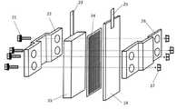
次に、図2を用いて、本発明のリン酸イオンと硝酸イオンを除去する汚染水浄化方法および装置における鉄炭素電池の詳細な構造を説明する。図中、21はボルト、22はプラスチック製の正極固定盤、15は炭素製の正極、23は正極の集電板、24は網状のプラスチック製セパレーター、14は鉄製の負極、25は負極の集電板、26はプラスチック製の負極固定盤、27はナットをそれぞれ表す。 Next, with reference to FIG. 2, the detailed structure of the iron-carbon battery in the contaminated water purification method and apparatus for removing phosphate ions and nitrate ions of the present invention will be described. In the figure, 21 is a bolt, 22 is a plastic positive electrode fixing plate, 15 is a carbon positive electrode, 23 is a positive electrode current collector, 24 is a mesh plastic separator, 14 is an iron negative electrode, and 25 is a negative electrode collection. The electric plate, 26 represents a plastic negative electrode fixing plate, and 27 represents a nut.
鉄炭素電池の組み立て方について図2を用いて説明する。鉄板(長さ15cm×幅4.5cm)を負極14、炭素板(長さ10cm×幅4cm)を正極15とし、負極14と正極15の間にプラスチック製の網(長さ10cm×幅4cm)を挟み、セパレーター24とし、プラスチック製の正極固定盤22とプラスチック製の負極固定盤26によって外側から挟み込み、ボルト21を通し、ナット27を締め、鉄炭素電池を組み立てた。 How to assemble the iron-carbon battery will be described with reference to FIG. An iron plate (
負極14で使用する鉄材料としては、いわゆる普通鋼、軟鉄などを使用することができる。 As the iron material used in the
また、この鉄材料の形状は、特に制限はない。例えば、平板状のもの、網状のもの、穴あき平板状(パンチングメタル)のもの、棒状のもの、網状のもの、粒子状のもの、糸状のものなどいずれも使用することができる。鉄の接触面積を大きくするために、網状や穴あき平板状、粒子状のものが好ましい。 Further, the shape of this iron material is not particularly limited. For example, a flat plate, a net, a perforated flat plate (punching metal), a rod, a net, a particle, a thread, and the like can be used. In order to increase the contact area of iron, net-like, perforated flat plate-like, and particle-like ones are preferable.
負極14で使用する材料としては、鉄よりも電位の貴な材料を使用する。鉄よりも電位の貴な材料としては、炭素材料、ステンレススチール、銅などが使用することができる。炭素材料の形態は、例えば、平板状のもの、棒状のもの、繊維状のもの、織布や不織布状のものなどが利用できる。 As the material used in the
鉄炭素電池では、負極14と正極15が向き合った状態となるように配置することが好ましい。 In the iron-carbon battery, it is preferable to arrange the
負極14と正極15との間隔は小さいほど電流が大きくなるために好ましいが、液の流動の容易性などを考慮すると1mm〜50mmが好ましく、2mm〜10mmが更に好ましい。被処理水の浴中の液の撹拌がない場合には両者の間隔を小さくし、浴中の液の撹拌がある場合には両者の間隔を大きくし、撹拌速度が大きくなるにつれて両者の間隔を大きくすることができる。 The smaller the distance between the
被処理水に鉄炭素電池を浸漬する場合、温度は室温でよく、特に加熱や冷却は必要としない。また、被処理水は中性領域でよいが、弱酸性や弱アルカリ性であってもよい。ただし、pHが8を超えると鉄が不動態となり水への溶解が進まなくなるので好ましくない。また、鉄炭素電池による水の処理においては物質移動を伴うので、被処理水の浴を撹拌することが好ましい。同様に、負極14と正極15と被処理水との接触面積も大きい方が好ましい。従って、負極14と正極15を多孔質状とすることが好ましい。 When the iron-carbon battery is immersed in the water to be treated, the temperature may be room temperature, and no special heating or cooling is required. The water to be treated may be in a neutral region, but may be weakly acidic or weakly alkaline. However, if the pH exceeds 8, iron becomes passivated and dissolution in water does not proceed, which is not preferable. Further, since mass transfer is involved in the treatment of water by the iron-carbon battery, it is preferable to stir the bath of the water to be treated. Similarly, it is preferable that the contact area between the
次に、図3を用いて、本発明のリン酸イオンと硝酸イオンを除去する汚染水浄化方法および装置における電池槽の詳細な構造を説明する。図中、31は電池槽の流入口、32は電池槽、33は試供水、34は電解装置の陽極とつなぐ正極、35は電解装置の陰極とつなぐ負極、36は電池槽の流出口、37は第1水槽、38は第2水槽、39は第3水槽、310は第4水槽、311は第5水槽、312は第6水槽、13は鉄炭素電池、14は鉄製の負極、15は炭素製の正極、16は導線、24はセパレーターをそれぞれ表す。 Next, with reference to FIG. 3, the detailed structure of the battery tank in the contaminated water purification method and apparatus for removing phosphate ions and nitrate ions of the present invention will be described. In the figure, 31 is the inlet of the battery tank, 32 is the battery tank, 33 is the test water supply, 34 is the positive electrode connected to the anode of the electrolytic device, 35 is the negative electrode connected to the cathode of the electrolytic device, 36 is the outlet of the battery tank, 37. Is the first water tank, 38 is the second water tank, 39 is the third water tank, 310 is the fourth water tank, 311 is the fifth water tank, 312 is the sixth water tank, 13 is an iron carbon battery, 14 is an iron negative electrode, and 15 is carbon. A positive electrode, 16 represents a lead wire, and 24 represents a separator.
電池槽32は第1水槽37、第2水槽38、第3水槽39、第4水槽310、第5水槽311、第6水槽312に仕切られた水槽である。これらの6つの水槽のサイズは幅5cm×奥行1.5cm×高さ8cmであり、6つの水槽の容積の合計、すなわち、電池槽32の容積は約800mLである。第1水槽から第6水槽の6つの水槽に鉄炭素電池13を1基ずつ計6基入れ、隣り合う鉄炭素電池の鉄製の負極14と炭素製の正極15を銅線16によって直列に接続した。試供水33は流入口31から供給され、第1水槽37に上部から入り、第1水槽37内の鉄炭素電池13に触れた後、第2水槽38に下部から入り、第2水槽38内の鉄炭素電池13に触れた後、第3水槽39に上部から入り、第3水槽39内の鉄炭素電池13に触れた後、第4水槽310の下部から入り、第4水槽310内の鉄炭素電池13に触れた後、第5水槽311に上部から入り、第5水槽311内の鉄炭素電池13に触れた後、第6水槽312の下部から入り、第6水槽312内の鉄炭素電池13に触れた後、流出口36から処理された試供水33が排出される。 The
[実施例1(鉄炭素電池による電力供給とリン酸除去および回収法)]
鉄板(長さ15cm×幅4.5cm)を負極14、炭素板(長さ10cm×4cm)を正極15とし、プラスチックの網をセパレーター24とした。試供水33は、麻機池の水をろ過した後、リン酸水素二ナトリウム・12水和物(Na2HPO4・12H2O)とリン酸2水素ナトリウム2水和物(NaH2PO4・2H2O)を等量ずつ用いて、リン酸態リン(PO4−P)濃度を0.05mmol/L(麻機池の流入溝のリン酸イオン濃度の年間の最大値、平均値の約10倍)、pHを7.0に調製した。実験は、1.6Lの試供水33を毎分26mLで流入口31から送り込み、流出口36から流れ出させ、処理後の試供水33を再度、流入口31に流し込み、試供水33を4回、循環させた。電池槽に入った試供水の体積の合計は、0.8Lであるため、約30分で電池槽内の試供水が入れ替わる。リン酸態リン濃度は、モリブデン青吸光光度法(非特許文献21)によって測定し、リン酸イオンが除去された割合を示す「リン酸イオンの除去率」を式6で定義した。
The iron plate (
1つの鉄炭素電池13を試供水33に入れた所、解放電圧は約0.5Vであった。鉄炭素電池13を直列に6個つないだ所、約3Vの電圧が発生した。1V以上であれば、2価の鉄イオンの酸化を用いた水素生産が可能であるため、鉄炭素電池からの電力の供給による水素生産は可能であることが分かった。 When one iron-
リン酸イオンの除去率は循環回数が1回の時は54.4%、2回の時は71.4%、3回の時は88.5%、4回の時は94.6%であった。 The removal rate of phosphate ions is 54.4% when the number of circulations is 1 time, 71.4% when the number of circulations is 2, 88.5% when the number of circulations is 3, and 94.6% when the number of circulations is 4 times. there were.
表1に電池水槽のpHと酸化還元電位(ORP)を示した。電池槽に流入した試供水のpHが上昇すると共に、酸化還元電位が負の値へ下降したことから、鉄炭素電池から鉄イオンが溶出したことが分かる。そのため、電池槽には、Fe2+とFe3+が存在する。Fe2+と陰イオンの溶解度積は、Fe3+の溶解度積と比較して非常に大きいため、Fe2+の沈殿はほとんど存在しないと考えられることから、Fe3+と陰イオンの反応で沈殿が生成したと判断した。Fe3+と反応して生成する沈殿物としては、Fe(OH)3(s)、FePO4(s)、Fe2(CO3)3(s)、Fe3(SO4)2(s)が挙がる。この4種の沈殿の中でFe2(CO3)3(s)とFe3(SO4)2(s)は溶解度積が非常に大きいため、沈殿は生成しないと考えられた。Fe(OH)3(s)とFePO4(s)に関する化学平衡と平衡定数から化学量論的に、FePO4(s)の沈殿が生成されたとは考えられなかったため、生成した沈殿は、Fe(OH)3(s)の沈殿であり、この沈殿の生成に伴って、リン酸(H3PO4−H3PO4−やH3PO42− )が共沈殿によって除去されたと考えられた。Table 1 shows the pH and redox potential (ORP) of the battery tank. As the pH of the test water flowing into the battery tank increased and the redox potential decreased to a negative value, it can be seen that iron ions were eluted from the iron-carbon battery. Therefore, Fe2+ and Fe3+ exist in the battery tank. Since the solubility product ofFe 2+ and anions is very large compared to the solubility product ofFe 3+ , it is considered that there is almost no precipitation ofFe 2+. Therefore, a precipitate was formed by the reaction ofFe 3+ and anions. I decided. The precipitates formed by reacting withFe 3+include Fe (OH) 3 (s), FePO4 (s), Fe2 (CO3 )3 (s), and Fe3 (SO4 )2 (s). Raise. Of these four types of precipitates, Fe2 (CO3 )3 (s) and Fe3 (SO4 )2 (s) had a very large solubility product, so it was considered that no precipitate was formed. From the chemical equilibrium and equilibrium constant for Fe (OH)3 (s) and FePO4 (s), it was not considered that a precipitate ofFePO 4 (s) was formed from the chemical equilibrium constant.(OH) a precipitation of 3 (s), with the generation of the precipitate, phosphate believed (H3 PO4- orH 3 PO 4 2- - H 3 PO 4) was removed by co-precipitation It was.
この実験を15時間継続した結果、水中のリン酸イオン除去率が100%になった。沈殿物を回収し、完全に乾燥させ、0.31gの回収物を得た。回収物の0.1倍の質量である0.031gを実験に用いた試供水の0.1倍の体積である160mLの硫酸溶液(1mol/L)に入れ、300rpmで30分間撹拌した後、溶液に溶出したリン酸イオン濃度を測定した。式7によるリン酸回収率は、水中のほぼ100%のリン酸イオンが沈殿物として回収できることが確認できた。
[実施例2](鉄炭素電池から供給された電力を用いた低電圧電解で生成した水素による硝酸イオン還元除去法と鉄塩によるリン酸凝集沈殿法を同時に実施)
以下に、図面を用いて、本発明の実施例を詳細に説明する。図4は本発明のリン酸イオンと硝酸イオンを除去する汚染水浄化方法および装置の実施例を説明する図で、13は鉄炭素電池、17は鉄イオンとリン酸イオンから生成した沈殿物、111は陽極槽、112は陰極槽、113は水素イオン交換膜、114は陽極、115は陰極、118は太陽光、119は還元槽、120は電解槽、31は電池槽32の流入口、32は電池槽、33は試供水、34は電解装置の陽極とつなぐ正極、35は電解装置の陰極とつなぐ負極、36は電池槽32の流出口、37は第1水槽、38は第2水槽、39は第3水槽、310は第4水槽、311は第5水槽、312は第6水槽、41は茶粕の供給および給水のためのバルブ、42は鉄イオンと還元性有機物が混合された溶液、43は空間、44は撹拌用モーター、45は陽極槽の廃液を還元槽へ返すパイプ、46は撹拌用プロペラ、47は使用済み還元性有機物の廃棄用バルブ、48はろ過機、49は還元槽119からポンプ410へのパイプ、410は還元槽119から陽極槽111への輸液ポンプ、411はポンプ410から陽極槽111へのパイプ、412は導線、413は陰極槽の排出口、414は陰極槽の流入口、415はポンプ416と流入口414をつなぐパイプ、416は沈殿槽420内の溶液419の上澄みを陰極槽112へ送る輸液ポンプ、417は沈殿槽420とポンプ416をつなぐパイプ、418は空間、419は電池水槽32で処理された後の試供水33、420は沈殿槽、421は沈殿物17の廃棄用バルブ、422は電池水槽32の流出口36と沈殿槽420をつなぐパイプ、をそれぞれ表す。[Example 2] (Simultaneous implementation of nitrate ion reduction removal method using hydrogen generated by low-voltage electrolysis using electric power supplied from an iron carbon battery and phosphoric acid coagulation precipitation method using iron salt)
Hereinafter, examples of the present invention will be described in detail with reference to the drawings. FIG. 4 is a diagram illustrating an embodiment of a contaminated water purification method and an apparatus for removing phosphate ions and nitrate ions of the present invention, in which 13 is an iron carbon cell and 17 is a precipitate formed from iron ions and phosphate ions. 111 is an anode tank, 112 is a cathode tank, 113 is a hydrogen ion exchange film, 114 is an anode, 115 is a cathode, 118 is sunlight, 119 is a reduction tank, 120 is an electrolytic tank, 31 is an inlet of a
本発明のリン酸イオンと硝酸イオンを除去する汚染水浄化方法および装置の主要な部分は、図4で示すように、電池槽32内でリン酸イオンを除去するための鉄イオンを溶出しながら発電する鉄炭素電池13と、陽極槽111内で2価の鉄イオンを含む水溶液中の鉄イオンの酸化によって陰極槽112内の水溶液を電解し水素イオンから水素を発生させ、陰極槽内の硝酸イオンを水素によって還元除去する電解槽120と、陽極槽111内で生成した3価の鉄イオンを還元して2価の鉄イオンに再生する還元槽119とで構成される。 The main part of the contaminated water purification method and apparatus for removing phosphate ions and nitrate ions of the present invention is, as shown in FIG. 4, while eluting iron ions for removing phosphate ions in the
還元槽119について、図5を用いて説明する。図5は、本発明の第2の実施例の還元槽119の詳細な構造を説明する図である。図中、119は還元槽、42は鉄イオンと還元性有機物が混合された溶液、44は撹拌用モーター、46は撹拌用プロペラ、47は使用済み還元性有機物の廃棄用バルブ、51から55は外部からの光を取り込む窓、をそれぞれ表す。 The
本実施例では、還元性有機物として茶粕を用い、照射する光として太陽光を用いた。還元槽119は太陽光を外部から光を取り込む窓51から55を通し取り込む。3価の鉄イオンは、太陽光を吸収しながら攪拌プロペラ46で攪拌された茶粕117と反応し、2価の鉄イオンに還元される。2価の鉄イオンと茶粕が混合された溶液42は、使用済みの茶粕は還元槽の上澄みをろ過機48で分離し、ポンプ416によって陽極槽111に導かれる。使用済みとなった茶粕は連続的に分離除去される。還元槽19の底は、使用済みの茶粕が効率よく使用済み茶粕廃棄バルブ47に向かうように、傾斜している。 In this example, tea grounds were used as the reducing organic matter, and sunlight was used as the light to irradiate. The
次に、実施例の電解部について説明する。電解部の主要な部分は、陽極槽111と陰極槽112と水素イオン交換膜113からなるが、順に説明する。 Next, the electrolytic part of the example will be described. The main part of the electrolytic part includes the
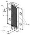
図4の陽極槽111の詳細について、図6を用いて説明する。図6で、45は陽極槽の廃液を還元槽に返すパイプ、411は還元槽からの2価の鉄イオンを含んだ溶液の供給用パイプ、61は陽極槽の第1室(下部)、62は陽極槽の第2室(中央部)、63は陽極槽の第3室(上部)、64はボルトを通す穴(陽極槽と陰極槽によって陽イオン交換膜を挟んで固定するためのボルトを通す穴)、をそれぞれ示す。 The details of the
前述した還元槽119で形成された2価の鉄イオンを含んだ溶液が供給用パイプ411から陽極槽の下部にある第1室61に供給される。第1室61が溶液で満たされると溶液は陽極槽の中央部にある第2室62に流れ込む。第2室62の内部には鉛直方向に10本の細い流路が平行に作られており、この流路は図4の陽極14の表面を流れる位置に配置されている。そのため、第1室61から流入した溶液は第2室62の内部で図4の陽極14の表面に余すことなく触れてから、陽極槽上部にある第3室63へ流れ出る。第3室63では、第2室62の内部で分岐していた流路からの流れが集められ、陽極槽で2価の鉄イオンが酸化されて生成された3価の鉄イオンを含む溶液はパイプ45を通って、図4の還元槽119に返され、2価の鉄イオンに再生される The solution containing divalent iron ions formed in the
次に、図7を用いて陰極槽112を説明する。図中、413は陰極槽の排出口、414は陰極槽の流入口、71は陰極槽の第1室(下部)、72は陰極極槽の第2室(中央部)、73は陽極槽の第3室(上部)、74はボルトを通す穴をそれぞれ表す。 Next, the
沈殿槽420の上澄み、すなわち、リン酸イオンが除去され、硝酸イオンが残留した試供水がポンプ416によって陰極槽の流入口414から供給される。供給された試供水は陰極槽の下部にある第1室71に供給される。第1室71が溶液で満たされると水は陽極槽の中央部にある第2室72に流れ込む。第2室72の内部には蛇行する細い流路が作られており、この流路は図4の陰極115の表面を流れる位置に配置されている。そのため、第1室71から流入した溶液は第2室72の内部で図4の陰極115の表面に余すことなく触れる。陰極15の表面で生成された水素によって、陰極槽112内で試供水に含まれる硝酸イオンが還元され、窒素ガスに変換され、陰極槽112の排出口413から水と共に排出される。 The supernatant of the
次に、図8を用いて、本発明の実施例からなる水素製造装置の陽極部、陰極部および陽イオン交換膜、等からなる電解部の全体の詳細構造を説明する。図中、112は陰極槽、113は水素イオン交換膜、114は陽極、115は陰極、81はボルト、82はナットをそれぞれ表す。 Next, with reference to FIG. 8, the overall detailed structure of the electrolytic part including the anode part, the cathode part and the cation exchange membrane of the hydrogen production apparatus according to the embodiment of the present invention will be described. In the figure, 112 is a cathode tank, 113 is a hydrogen ion exchange membrane, 114 is an anode, 115 is a cathode, 81 is a bolt, and 82 is a nut.
陽極114と陰極115および水素イオン交換膜113からなる電解装置の組み立て方法について、図8を用いて説明する。陽極114と陰極115には、網状の白金めっき付チタン電極(幅10cm×長さ30cm)を用いた。陽極114と陰極115は網状のチタンの周囲に板状のチタンを接合した後、白金でメッキした。陽極114と陰極115によって陽イオン交換膜113(幅10cm×長さ30cm)を挟んだ後、陰極槽114と陽極槽115によって外側から挟み込み、ボルト81を通し、ナット82を締め、電解部を組み立てた。 A method of assembling the electrolytic device including the
次に、本実施例における各部の条件について説明する。還元槽119においては、以下の条件で行われた。 Next, the conditions of each part in this embodiment will be described. In the
茶葉を浸す電解液としては、硝酸鉄水溶液を用いた。Fe(III)/Fe(II)のレッドクスポテンシャルは全鉄イオン濃度やFe(III)/Fe(II)の割合、pH、陰イオン種などの影響をうける。式(1)の反応はFe(III)イオン濃度が高く、pHも高いほど進行し易い。一方、式(2)の反応は、Fe(II)イオン濃度が高く、pHは低い方がよい。どちらの反応も逆反応と平衡状態にあるため、反応速度を高め、広い範囲で平衡を移行させるためには活性の高い触媒および効率の良い光照射法が重要になる。 An aqueous iron nitrate solution was used as the electrolytic solution for immersing the tea leaves. The redx potential of Fe (III) / Fe (II) is affected by the total iron ion concentration, the ratio of Fe (III) / Fe (II), pH, anion species, and the like. The reaction of formula (1) is more likely to proceed as the Fe (III) ion concentration is higher and the pH is higher. On the other hand, in the reaction of the formula (2), it is preferable that the Fe (II) ion concentration is high and the pH is low. Since both reactions are in equilibrium with the reverse reaction, a highly active catalyst and an efficient light irradiation method are important for increasing the reaction rate and shifting the equilibrium over a wide range.
本実施例では、電解液として、606gの硝酸鉄(III)(Fe(NO3)3・9H2O)と10Lの常温の水を用いて3価の鉄イオン濃度が0.15mol/L(150mM)の試供水を調製した。10Lの試供水と破断状態にした最長3mmである1kgの茶粕を図5の反応容器に入れた。還元槽119の容積は12.5Lである。In this embodiment, as the electrolytic solution, the trivalent iron ion concentration using iron nitrate(III) (Fe (NO 3 ) 3 · 9H 2 O) and cold water 10L of 606g is 0.15 mol / L ( 150 mM) of test water was prepared. 10 L of test water and 1 kg of tea grounds having a maximum length of 3 mm in a broken state were placed in the reaction vessel of FIG. The volume of the
光照射の方法は、できるだけ光が触媒と溶液に効率よく照射されなければいけない。本実施例では太陽光を用いた。太陽光が逃げないようにミラーやアルミホイル等を使用し、取り込み効率の高い光学系を用いる。太陽光の取り込み窓51から55の窓材には、透過率が高く、比較的安価なパイレックスを用いた。パイレックスの代わりに、透過率の高いプラスチックを用いることも出来る。 In the method of light irradiation, the catalyst and the solution must be irradiated with light as efficiently as possible. In this example, sunlight was used. Use mirrors, aluminum foil, etc. to prevent sunlight from escaping, and use an optical system with high capture efficiency. For the window materials of the
本実施例では、鉄イオンと茶粕が混合された溶液42をより分散させるために、撹拌用プロペラ46を撹拌用モーター44で回転攪拌した。還元槽119の底面には傾斜があり、プロペラ46の下付近に沈殿した茶粕が集まる構造になっており、プロペラ46の撹拌によって沈殿した茶粕が再び還元槽119の内部を浮遊する。プロペラ46の撹拌を止めると、沈殿した茶粕は還元槽119の底面の傾斜によって使用済み茶粕廃棄用バルブ47の付近に集まる構造になっており、使用済みの茶粕を還元槽119から取り出すことができる。そして、3価の鉄イオンを還元して生成された2価の鉄イオンを含む電解液は、茶粕と分離された後、ポンプ410で陽極槽111に送り込まれる。 In this example, in order to further disperse the
陽極槽に送りこまれた電解液は、水素イオン交換膜113によって陽極槽と陰極槽が仕切られた2槽式電解セルで式2の反応を起こす。2槽式電解セルを仕切る膜としては半透膜、透析用浸透膜、イオン交換膜や塩橋、セラミック膜などが利用できるが、水素イオンの移動度が鉄イオンの移動度に比べて充分大きい必要があるので、水素イオン交換膜が望ましく、本実施例では、水素イオン交換膜(ナフィオン、デュポン社製)を用いた。 The electrolytic solution sent into the anode tank causes the reaction of
水素発生側の陰極115としては水素過電圧の小さな材料が望ましく、白金やニッケル、白金などを微量に担持したカーボン電極、白金がメッキされたチタン電極などが使用できる。本実施例では、コストを考慮し白金がメッキされたチタン電極を用いた。 As the
一方、2価の鉄イオンの酸化を行う陽極114としては上記の電極の他に白金を担持しないカーボン電極でも使用できる。本実施例では、コストを考慮し白金がメッキされたチタン電極を用いた。 On the other hand, as the
電解電圧を下げるためには電極間距離を短くしたり、反応温度を高くしたり、電極電流密度を下げる、集電材を使うといった工夫が重要である。本実施例では、電極間距離は水素イオン交換膜の厚みとした。反応温度は、常温で行った。電極電流密度は3アンペア/平方センチにした。また、集電効果を高めるために、電極構造を図8で示すように、網状の電極の周囲に、板状の枠を設けた。 In order to lower the electrolytic voltage, it is important to shorten the distance between the electrodes, raise the reaction temperature, lower the electrode current density, and use a current collector. In this example, the distance between the electrodes is the thickness of the hydrogen ion exchange membrane. The reaction temperature was room temperature. The electrode current density was 3 amps / cm2. Further, in order to enhance the current collecting effect, as shown in FIG. 8, a plate-shaped frame is provided around the net-like electrode.
電解が進行すると陽極114周辺の2価の鉄イオン濃度が減少するので、電極周辺の水溶液が撹拌される、または還元槽119と直結して常に2価の鉄イオン濃度の高い溶液が循環されるシステムが望ましい。 As the electrolysis progresses, the divalent iron ion concentration around the
硝酸イオンとリン酸イオンの同時除去方法の条件の最適化をするために、以下の実験を行った。
(実験1)
試供水33として、麻機池の水をろ過した後、硝酸カリウム(KNO3)を用いて、硝酸態窒素(NO3−N)濃度を2mmol/L、リン酸水素二ナトリウム・12水和物(Na2HPO4・12H2O)とリン酸2水素ナトリウム2水和物(NaH2PO4・2H2O)を等量ずつ用いて、リン酸態リン(PO4−P)濃度を2mmol/L、pHを7.0に調製した。
電解液42として、606gの硝酸鉄(III)(Fe(NO3)3・9H2O)と10Lの常温の水を用いて3価の鉄イオン濃度が0.15mol/L(150mM)の試供水を調製した。
10Lの電解液42と破断状態にした最長3mmである1kgの茶粕を図5の還元槽119に入れ、1,000lmのLED電球を8個(紫外光は含まず、窓53と54付近の照度は約20,000lux、快晴時の太陽光の10分の1の強度)を用いて、光を照射しながら、還元槽119内を300rpmで撹拌し、2価の鉄イオンの濃度の減少を防止しつつ、ポンプ410を用いて、電解液を毎分50mLで送り、還元槽119と陽極槽111を循環させた。
同時に、試供水を毎分26mLで電池槽32に、電池槽32で処理された試供水33を電解装置412の陰極槽112に送り込み、陰極槽112で処理した試供水を再度、電池槽32に送ることによって、試供水を循環させ、硝酸態窒素、亜硝酸態窒素(NO2−N)アンモニア態窒素(NH4−N)、リン酸態リンの濃度の変化を測定した。硝酸は亜鉛還元−ナフチルエチレンジアミン吸光光度法(非特許文献21)、亜硝酸は、ナフチルエチレンジアミン吸光光度法(非特許文献21)、アンモニアは、インドフェノール青吸光光度法(非特許文献21)で測定した。The following experiments were conducted to optimize the conditions for the simultaneous removal method of nitrate and phosphate ions.
(Experiment 1)
After filtering the water in the hemp pond as the
As the
10 L of
At the same time, the test water supply at 26 mL / min was sent to the
実験1におけるリン酸態リン濃度は、20時間でほぼ0mmol/Lになり、水中のリン酸イオンがすべて除去された。 The phosphate phosphorus concentration in
通常、電池槽32内の試供水のpHが低い(水素イオン濃度が高い)と、つまり酸性であるほど、鉄負極14の溶解速度は大きくなり、リン酸イオンとの反応速度が大きくなることが期待される。本発明において、陰極115での水素生成をセーブしながら陰極槽112で処理された後の試供水を電池槽32に送り、試供水を循環させると、陰極槽112から水素イオンが供給され、電池槽32に供給される試供水のpHを低くすることができ、環境に負荷を与えないで、電池槽32内の試供水に含まれるリン酸イオンと反応させるための鉄イオンの溶出速度を大きくすることが可能になった。 Normally, the lower the pH of the test water in the battery tank 32 (higher hydrogen ion concentration), that is, the more acidic it is, the higher the dissolution rate of the iron
通常、電池槽32内の試供水のpHが5.0に満たないと、一度、沈殿除去したリン化合物の溶解度が増加して効率的にリンを除去できなくなる。本発明において、陰極115で十分に水素生成を行いながら陰極槽112で処理された後の試供水を電池槽32に送り、試供水を循環させると、陰極槽112で水素イオンが消費され、電池槽32に供給される試供水のpHを高く(水素イオン濃度を低く)することができ、電池槽32内の試供水に含まれるリン酸イオンが沈殿しやすくなる。 Normally, if the pH of the test water in the
通常、電池槽32内の試供水のpHが8.0を超えると、溶解した金属イオンが水酸化物イオンと反応して水酸化物を形成してしまうため、リン酸化合物の形成が抑制されてしまう。本発明において、陰極115での水素生成をセーブしながら陰極槽112で処理された後の試供水を電池槽32に送り、試供水を循環させると、陰極槽112から水素イオンが供給され、電池槽32に供給される試供水のpHを低くすることができ、環境に負荷を与えないで、電池槽32内の試供水に含まれる金属イオンとリン酸イオンと反応させる特に好ましいpHである7.0に調整することが可能になった。 Normally, when the pH of the test water in the
実験1における硝酸態窒素濃度は、60時間で1mmol/Lになり、水中の硝酸イオンの50%が除去された。亜硝酸態窒素濃度は実験期間中、常に0mmol/Lであったが、アンモニア態窒素濃度は常に0.2mmol/Lであったことより、硝酸イオンが還元され、除去されたと考えられた。処理水の鉄イオン濃度は0mmol/Lであり、実験期間中は約1mA×1Vの電流と陰極から気体の発生が目視で確認できたため、低電圧電解による水素生成が起きていたと考えられる。 The nitrate nitrogen concentration in
pHが7の時において、亜硝酸イオン(NO2−)とアンモニウムイオン(NH4+)が同モル存在する条件下では、亜硝酸イオンが窒素ガス(N2)に還元される場合の半反応式(式8)とアンモニウムイオンが窒素ガスへ酸化される場合の半反応式(式9)が成立し、Total equation(式10)におけるギブズの自由エネルギーは負であるため、陰極からの微量な水素ガスと電池槽から供給された還元的な電位の水質によって、水中に存在する亜硝酸イオンとアンモニウムイオンから共に窒素ガスを生成する反応が進み、硝酸イオンが除去されたことが示唆された。
通常、水中の溶存酸素濃度(DO)が高いと、水中に存在する硝酸イオンは還元されない。本発明では、電池槽32内において、鉄炭素電池13によって水中の溶存酸素が消費されるため、電池槽32からの排水を陰極槽112に送ることによって、陰極槽112内において、陰極115の表面で硝酸イオンを窒素ガスに還元することが可能になった。 Normally, when the dissolved oxygen concentration (DO) in water is high, nitrate ions existing in water are not reduced. In the present invention, since dissolved oxygen in water is consumed by the iron-
通常、水中の酸化還元電位(ORP)が正の値(酸化的)であると、水中に存在する硝酸イオンは還元されにくい。本発明では、電池槽32内の仕切られた第1水槽37、第2水槽38、…、第6水槽312と進むにつれて、水中の酸化還元電位が負の値でかつ下がり続けるため、電池槽32からの排水を陰極槽112に送ることによって、陰極槽112内において、陰極115の表面で硝酸イオンを窒素ガスへ高効率で還元することが可能になった。 Normally, when the redox potential (ORP) in water is a positive value (oxidative), nitrate ions existing in water are difficult to be reduced. In the present invention, the redox potential in the water becomes a negative value and continues to decrease as the process proceeds from the partitioned
通常、水中の水素イオン(H+)濃度が低いと、水中に存在する硝酸イオンは還元されにくい。本発明では、還元槽119内において、3価の鉄イオンが2価の鉄イオンに還元される際に、水から水素イオンが生成され、陽極槽111から水素イオン交換膜113を経由して、陰極槽112に供給されるため、中性(pHが7)付近の試供水が電池槽32に供給されたとしても、電池槽32から陰極槽112に送られた試供水の水素イオン濃度が高められ、陰極槽112内において、陰極115の表面で硝酸イオンを窒素ガスに還元することが可能になった。Normally, when the hydrogen ion (H+ ) concentration in water is low, the nitrate ion existing in water is difficult to be reduced. In the present invention, when trivalent iron ions are reduced to divalent iron ions in the
(実験2)
快晴時に除去装置を麻機池で活用した。麻機池の流入溝付近で採取した水を毎分26mLで電池槽32の流入口31に流し込み、電解装置412の陰極槽112の排出口413から流れ出た処理水を再度、電池槽32に流し込み、実験1と同じ流速で循環させた。(Experiment 2)
The removal device was used in the hemp pond in fine weather. The water collected near the inflow groove of the hemp pond is poured into the
処理前のリン酸態リン濃度は0.5mg/Lであった。リン酸イオンは、1回目の循環で60%以上が除去され、4回の循環の後、90%以上が除去された。処理前の硝酸態窒素濃度は1.5mg/Lであった。硝酸イオンは、2回目の循環まで、除去率は低かったが、3回目以降、徐々に高まり、4回の循環の後、約20%が除去された。 The phosphate phosphorus concentration before the treatment was 0.5 mg / L. Phosphate ions were removed in an amount of 60% or more in the first circulation and 90% or more after the fourth circulation. The nitrate nitrogen concentration before the treatment was 1.5 mg / L. The removal rate of nitrate ion was low until the second circulation, but gradually increased after the third circulation, and about 20% was removed after the fourth circulation.
(実験3)
巴川と駿府城のお堀で実施した場合も、同様な結果を得たことから、一般的な河川や湖沼の水を流し込むだけで、硝酸イオンとリン酸の除去が同時に可能なシステムの開発に成功したことが確認できた。(Experiment 3)
Similar results were obtained when the moat was carried out in the Tomoe River and Sunpu Castle, so it was possible to develop a system that can remove nitrate ions and phosphoric acid at the same time by simply pouring water from general rivers and lakes. I was able to confirm that it was successful.
(実験4)
浄化槽や下水処理場で処理された後の水を用いた場合における、リン酸態リン濃度は、6時間でほぼ0mmol/Lになり、水中のリン酸イオンがすべて除去された。硝酸態窒素濃度は、20時間で1mmol/L、60時間で0.2mmol/Lになり、水中の硝酸イオンの90%が除去された。亜硝酸態窒素濃度は実験期間中、常に0mmol/Lであったが、アンモニア態窒素濃度は常に0.2mmol/Lであったことより、硝酸イオンが還元され、除去されたと考えられた。実験1と同様に、処理水の鉄イオン濃度は0mmol/Lであり、実験期間中は約1mA×1Vの電流と陰極から気体の発生が目視で確認できたため、実験3においても、低電圧電解による水素生成が起きていたと考えられる。(Experiment 4)
When water after treatment in a septic tank or a sewage treatment plant was used, the phosphate phosphorus concentration became almost 0 mmol / L in 6 hours, and all phosphate ions in the water were removed. The nitrate nitrogen concentration reached 1 mmol / L in 20 hours and 0.2 mmol / L in 60 hours, and 90% of nitrate ions in the water were removed. The nitrite nitrogen concentration was always 0 mmol / L during the experimental period, but the ammonia nitrogen concentration was always 0.2 mmol / L, suggesting that nitrate ions were reduced and removed. Similar to
実施例では、鉄板を負極、炭素板を正極とした鉄炭素電池から溶出する鉄イオンによって水中のリン酸イオンを沈殿させて除去し、収集した沈殿物からリン酸が回収された。同時に、鉄炭素電池から供給される電力を用いた水電解によって製造した水素を用いて、溶液中の硝酸イオンが還元されて除去された。加えて、硝酸イオンを還元するための水素は、太陽光と茶粕を用いた3価の鉄イオンから2価の鉄イオンへの還元と2価の鉄イオンの酸化による1V以下の低電圧水電解を組み合わせた、安全・安価かつエネルギー消費を半減させた水素製造法を用いて供給された。 In the examples, phosphate ions in water were precipitated and removed by iron ions eluted from an iron-carbon battery having an iron plate as a negative electrode and a carbon plate as a positive electrode, and phosphoric acid was recovered from the collected precipitate. At the same time, nitrate ions in the solution were reduced and removed using hydrogen produced by water electrolysis using electric power supplied from the iron-carbon battery. In addition, hydrogen for reducing nitrate ions is low-voltage water of 1 V or less due to reduction of trivalent iron ions to divalent iron ions using sunlight and tea cake and oxidation of divalent iron ions. It was supplied using a safe, inexpensive, and halved energy production method that combines electrolysis.
11 硝酸イオン
12 リン酸イオン
13 鉄炭素電池
14 鉄製の負極
15 炭素製の正極
16 導線
17 鉄イオンとリン酸イオン12から生成した沈殿物
18 鉄炭素電池13で処理した後の溶液
19 鉄炭素電池13から供給される電力
111 陽極槽
112 陰極槽
113 水素イオン交換膜
114 陽極
115 陰極
116 電源
117 茶粕等の還元性有機物
118 太陽光
119 還元槽
120 電解槽
21 ボルト
22 プラスチック製の正極固定盤
23 正極の集電板
24 網状のプラスチック製セパレーター
25 負極の集電板
26 プラスチック製の負極固定盤
27 ナット
31 電池槽の流入口
32 電池槽
33 試供水
34 電解装置の陽極とつなぐ正極
35 電解装置の陰極とつなぐ負極
36 電池槽の流出口
37 第1水槽
38 第2水槽
39 第3水槽
310 第4水槽
311 第5水槽
312 第6水槽
41 茶粕の供給および給水のためのバルブ
42 電解液(鉄イオン)と還元性有機物が混合された溶液
43 空間
44 撹拌用モーター
45 陽極槽の廃液を還元槽へ返すパイプ
46 撹拌用プロペラ
47 使用済み還元性有機物の廃棄用バルブ
48 ろ過機
49 還元槽119からポンプ410へのパイプ
410 還元槽119から陽極槽111への輸液ポンプ
411 ポンプ410から陽極槽111へのパイプ
412 導線
413 陰極槽の排出口
414 陰極槽の流入口
415 ポンプ416と流入口414をつなぐパイプ
416 沈殿槽420内の溶液419の上澄みを陰極槽112へ送る輸液ポンプ
417 沈殿槽420とポンプ416をつなぐパイプ
418 空間
419 電池槽32で処理された後の試供水33
420 沈殿槽
421 沈殿物17の廃棄用バルブ
422 電池水槽32の流出口36と沈殿槽420をつなぐパイプ
51 外部からの光を取り込む窓
52 外部からの光を取り込む窓
53 外部からの光を取り込む窓
54 外部からの光を取り込む窓
55 外部からの光を取り込む窓
61 陽極槽の第1室(下部)
62 陽極槽の第2室(中央部)
63 陽極槽の第3室(上部)
64 ボルトを通す穴
71 陰極槽の第1室(下部)
72 陰極極槽の第2室(中央部)
73 陽極槽の第3室(上部)
74 ボルトを通す穴
81 ボルト
82 ナット11 Nitrate ion 12 Phosphate ion 13 Iron carbon battery 14 Iron negative electrode 15 Carbon positive electrode 16 Conductor wire 17 Precipitate generated from iron ion and phosphate ion 12 18 Solution after treatment with iron carbon battery 13 19 Iron carbon battery Power supplied from 13 111 Anode tank 112 Cathode tank 113 Hydrogen ion exchange film 114 Anode 115 Cathode 116 Power supply 117 Reducing organic substances such as tea cake 118 Sunlight 119 Reduction tank 120 Electrode tank 21 Bolt 22 Plastic positive electrode fixing plate 23 Positive electrode current collector 24 Net-like plastic separator 25 Negative electrode current collector plate 26 Plastic negative electrode fixing plate 27 Nut 31 Battery tank inflow port 32 Battery tank 33 Trial water supply 34 Positive electrode connected to the anode of the electrolytic device 35 Electrode device Negative electrode connected to the cathode 36 Outlet of battery tank 37 1st water tank 38 2nd water tank 39 3rd water tank 310 4th water tank 311 5th water tank 312 6th water tank 41 Valve for supply and water supply of tea cake 42 Electrolyte (iron) Solution of mixed ion) and reducing organic matter 43 Space 44 Stirring motor 45 Pipe that returns the waste liquid from the anode tank to the reducing tank 46 Stirring propeller 47 Disposal valve for used reducing organic matter 48 Filter 49 From reduction tank 119 Pipe 410 to pump 410 Infusion pump 411 from reduction tank 119 to anode tank 111 Pipe 412 from pump 410 to anode tank 111 Lead wire 413 Electrode tank outlet 414 Electrode tank inlet 415 Connect pump 416 and inlet 414 Pipe 416 Infusion pump 417 that sends the supernatant of the solution 419 in the settling tank 420 to the cathode tank 112 Pipe 418 that connects the settling tank 420 and the pump 416 Space 419 Test water 33 after being treated in the battery tank 32.
420
62 Second chamber (central part) of the anode tank
63 Room 3 (upper part) of the anode tank
64 Hole for passing
72 Second chamber (central part) of the cathode electrode tank
73 Room 3 (upper part) of the anode tank
74 Holes for
Claims (11)
Translated fromJapaneseThe reduction tank for reducing iron ions used for electrolysis of contaminated water has a supply unit that can continuously supply reducing organic matter and a reducing organic matter separation unit that continuously discharges used reducing organic matter. The contaminated water purification device according to claim 10, wherein the contaminated water purification device is connected.
Priority Applications (1)
| Application Number | Priority Date | Filing Date | Title |
|---|---|---|---|
| JP2019232456AJP7391366B2 (en) | 2019-12-24 | 2019-12-24 | Contaminated water purification method and device for removing phosphate ions and nitrate ions |
Applications Claiming Priority (1)
| Application Number | Priority Date | Filing Date | Title |
|---|---|---|---|
| JP2019232456AJP7391366B2 (en) | 2019-12-24 | 2019-12-24 | Contaminated water purification method and device for removing phosphate ions and nitrate ions |
Publications (2)
| Publication Number | Publication Date |
|---|---|
| JP2021100744Atrue JP2021100744A (en) | 2021-07-08 |
| JP7391366B2 JP7391366B2 (en) | 2023-12-05 |
Family
ID=76651155
Family Applications (1)
| Application Number | Title | Priority Date | Filing Date |
|---|---|---|---|
| JP2019232456AActiveJP7391366B2 (en) | 2019-12-24 | 2019-12-24 | Contaminated water purification method and device for removing phosphate ions and nitrate ions |
Country Status (1)
| Country | Link |
|---|---|
| JP (1) | JP7391366B2 (en) |
Cited By (9)
| Publication number | Priority date | Publication date | Assignee | Title |
|---|---|---|---|---|
| CN114804304A (en)* | 2022-05-06 | 2022-07-29 | 泉州师范学院 | Method for recovering phosphorus in sewage by electrolysis |
| US11502323B1 (en) | 2022-05-09 | 2022-11-15 | Rahul S Nana | Reverse electrodialysis cell and methods of use thereof |
| US11502322B1 (en) | 2022-05-09 | 2022-11-15 | Rahul S Nana | Reverse electrodialysis cell with heat pump |
| CN115465923A (en)* | 2022-07-28 | 2022-12-13 | 湖南大学 | Method for treating nitrate wastewater by using copper-nickel alloy three-dimensional composite electrode loaded with copper hydroxide |
| CN116395886A (en)* | 2023-03-28 | 2023-07-07 | 宝武集团鄂城钢铁有限公司 | Coke oven gas condensate pretreatment of water system |
| US11855324B1 (en) | 2022-11-15 | 2023-12-26 | Rahul S. Nana | Reverse electrodialysis or pressure-retarded osmosis cell with heat pump |
| WO2024129250A1 (en)* | 2022-12-15 | 2024-06-20 | Wisconsin Alumni Research Foundation | Electrochemical phosphate removal and recovery cells |
| US12040517B2 (en) | 2022-11-15 | 2024-07-16 | Rahul S. Nana | Reverse electrodialysis or pressure-retarded osmosis cell and methods of use thereof |
| US12341228B2 (en) | 2022-11-15 | 2025-06-24 | Rahul S. Nana | Reverse electrodialysis or pressure-retarded osmosis cell and methods of use thereof |
Citations (3)
| Publication number | Priority date | Publication date | Assignee | Title |
|---|---|---|---|---|
| JP2000334465A (en)* | 1999-05-26 | 2000-12-05 | Masaaki Nagakura | Device for removing nitrogen and phosphorus in waste water |
| JP2004066223A (en)* | 2002-06-10 | 2004-03-04 | Shunji Nishi | Electrolyte waste water treatment device, electrode used for the device and power generation device |
| JP2011115728A (en)* | 2009-12-04 | 2011-06-16 | Masakazu Kuroda | Method of removing nitrogen and phosphorus in water and coloring of water |
- 2019
- 2019-12-24JPJP2019232456Apatent/JP7391366B2/enactiveActive
Patent Citations (3)
| Publication number | Priority date | Publication date | Assignee | Title |
|---|---|---|---|---|
| JP2000334465A (en)* | 1999-05-26 | 2000-12-05 | Masaaki Nagakura | Device for removing nitrogen and phosphorus in waste water |
| JP2004066223A (en)* | 2002-06-10 | 2004-03-04 | Shunji Nishi | Electrolyte waste water treatment device, electrode used for the device and power generation device |
| JP2011115728A (en)* | 2009-12-04 | 2011-06-16 | Masakazu Kuroda | Method of removing nitrogen and phosphorus in water and coloring of water |
Cited By (15)
| Publication number | Priority date | Publication date | Assignee | Title |
|---|---|---|---|---|
| CN114804304A (en)* | 2022-05-06 | 2022-07-29 | 泉州师范学院 | Method for recovering phosphorus in sewage by electrolysis |
| US11699803B1 (en) | 2022-05-09 | 2023-07-11 | Rahul S Nana | Reverse electrodialysis cell with heat pump |
| US11502323B1 (en) | 2022-05-09 | 2022-11-15 | Rahul S Nana | Reverse electrodialysis cell and methods of use thereof |
| US11502322B1 (en) | 2022-05-09 | 2022-11-15 | Rahul S Nana | Reverse electrodialysis cell with heat pump |
| US12107308B2 (en) | 2022-05-09 | 2024-10-01 | Rahul S Nana | Reverse electrodialysis cell and methods of use thereof |
| US11563229B1 (en) | 2022-05-09 | 2023-01-24 | Rahul S Nana | Reverse electrodialysis cell with heat pump |
| US11611099B1 (en) | 2022-05-09 | 2023-03-21 | Rahul S Nana | Reverse electrodialysis cell and methods of use thereof |
| CN115465923B (en)* | 2022-07-28 | 2024-02-13 | 湖南大学 | Method for treating nitrate wastewater by copper-nickel alloy three-dimensional composite electrode loaded with copper hydroxide |
| CN115465923A (en)* | 2022-07-28 | 2022-12-13 | 湖南大学 | Method for treating nitrate wastewater by using copper-nickel alloy three-dimensional composite electrode loaded with copper hydroxide |
| US11855324B1 (en) | 2022-11-15 | 2023-12-26 | Rahul S. Nana | Reverse electrodialysis or pressure-retarded osmosis cell with heat pump |
| US12040517B2 (en) | 2022-11-15 | 2024-07-16 | Rahul S. Nana | Reverse electrodialysis or pressure-retarded osmosis cell and methods of use thereof |
| US12341228B2 (en) | 2022-11-15 | 2025-06-24 | Rahul S. Nana | Reverse electrodialysis or pressure-retarded osmosis cell and methods of use thereof |
| US12374711B2 (en) | 2022-11-15 | 2025-07-29 | Rahul S. Nana | Reverse electrodialysis or pressure-retarded osmosis cell with heat pump |
| WO2024129250A1 (en)* | 2022-12-15 | 2024-06-20 | Wisconsin Alumni Research Foundation | Electrochemical phosphate removal and recovery cells |
| CN116395886A (en)* | 2023-03-28 | 2023-07-07 | 宝武集团鄂城钢铁有限公司 | Coke oven gas condensate pretreatment of water system |
Also Published As
| Publication number | Publication date |
|---|---|
| JP7391366B2 (en) | 2023-12-05 |
Similar Documents
| Publication | Publication Date | Title |
|---|---|---|
| JP7391366B2 (en) | Contaminated water purification method and device for removing phosphate ions and nitrate ions | |
| Tee et al. | Review on hybrid energy systems for wastewater treatment and bio-energy production | |
| CN101198550B (en) | Reverse electrodialysis and electrochemical wastewater treatment methods for nitrogenous compounds | |
| Şengil | Treatment of dairy wastewaters by electrocoagulation using mild steel electrodes | |
| Prosnansky et al. | High-rate denitrification and SS rejection by biofilm-electrode reactor (BER) combined with microfiltration | |
| CN104386874B (en) | A kind of wiring board industry high-concentration waste liquor treating process | |
| CN103771650B (en) | A kind for the treatment of process of coal gasification waste water | |
| CN101264946B (en) | Iron-carbon pipe component capable of purifying waste water, integrated magnetoelectric oxidation biological filter chamber and application system | |
| US20090008267A1 (en) | Process and method for the removal of arsenic from water | |
| CN106800356A (en) | A kind of advanced treatment of wastewater regeneration device based on biochemical and electrolysis tech | |
| Mahvi et al. | Removal of cadmium from industrial effluents by electrocoagulation process using aluminum electrodes | |
| CN101269898B (en) | Advanced treatment apparatus for printing and dyeing wastewater | |
| CN111423066A (en) | Sewage treatment system | |
| CN112479478A (en) | System and method for performing pretreatment-biochemical treatment on raw material medicine wastewater by utilizing two-effect evaporation-micro-electrolysis catalytic oxidation | |
| CN110668617A (en) | Method for treating industrial wastewater difficult to degrade | |
| CN117023919A (en) | Multistage treatment system and multistage treatment process for gas field produced water | |
| Ammar et al. | Removal of inorganic pollutants and recovery of nutrients from wastewater using electrocoagulation: a review | |
| CN106630113A (en) | Denitrification method of ammonia-nitrogen wastewater and microbial desalination tank | |
| CN105692972A (en) | Industrial wastewater advanced treatment and cyclic utilization method | |
| US20220227649A1 (en) | Electrohydromodulating process for recovering nutrients, mineralizing organics, and inactivating pathogens in wastewater | |
| CN117142712A (en) | A method for processing domestic waste leachate membrane concentrate | |
| KR20160053901A (en) | Phosphorus treatment and fertilized system for wastewater equipped with redox metal reactor | |
| CN116514299A (en) | Landfill leachate membrane concentrate processing system | |
| CN109133442A (en) | It is drained outside a kind of pair of breeding wastewater and propose the improved system of mark and its process | |
| CN105884130B (en) | A kind of laboratory process for treating waste liquor, system |
Legal Events
| Date | Code | Title | Description |
|---|---|---|---|
| A80 | Written request to apply exceptions to lack of novelty of invention | Free format text:JAPANESE INTERMEDIATE CODE: A80 Effective date:20200109 | |
| A521 | Request for written amendment filed | Free format text:JAPANESE INTERMEDIATE CODE: A523 Effective date:20201029 | |
| A621 | Written request for application examination | Free format text:JAPANESE INTERMEDIATE CODE: A621 Effective date:20221112 | |
| A871 | Explanation of circumstances concerning accelerated examination | Free format text:JAPANESE INTERMEDIATE CODE: A871 Effective date:20221112 | |
| RD02 | Notification of acceptance of power of attorney | Free format text:JAPANESE INTERMEDIATE CODE: A7422 Effective date:20221112 | |
| A131 | Notification of reasons for refusal | Free format text:JAPANESE INTERMEDIATE CODE: A131 Effective date:20230131 | |
| A521 | Request for written amendment filed | Free format text:JAPANESE INTERMEDIATE CODE: A523 Effective date:20230331 | |
| A131 | Notification of reasons for refusal | Free format text:JAPANESE INTERMEDIATE CODE: A131 Effective date:20230530 | |
| A521 | Request for written amendment filed | Free format text:JAPANESE INTERMEDIATE CODE: A523 Effective date:20230728 | |
| A131 | Notification of reasons for refusal | Free format text:JAPANESE INTERMEDIATE CODE: A131 Effective date:20230815 | |
| A521 | Request for written amendment filed | Free format text:JAPANESE INTERMEDIATE CODE: A523 Effective date:20230930 | |
| TRDD | Decision of grant or rejection written | ||
| A01 | Written decision to grant a patent or to grant a registration (utility model) | Free format text:JAPANESE INTERMEDIATE CODE: A01 Effective date:20231017 | |
| A61 | First payment of annual fees (during grant procedure) | Free format text:JAPANESE INTERMEDIATE CODE: A61 Effective date:20231115 | |
| R150 | Certificate of patent or registration of utility model | Ref document number:7391366 Country of ref document:JP Free format text:JAPANESE INTERMEDIATE CODE: R150 |