JP2021100301A - Power conversion system and control device - Google Patents
Power conversion system and control deviceDownload PDFInfo
- Publication number
- JP2021100301A JP2021100301AJP2019229990AJP2019229990AJP2021100301AJP 2021100301 AJP2021100301 AJP 2021100301AJP 2019229990 AJP2019229990 AJP 2019229990AJP 2019229990 AJP2019229990 AJP 2019229990AJP 2021100301 AJP2021100301 AJP 2021100301A
- Authority
- JP
- Japan
- Prior art keywords
- command value
- power
- control
- control device
- power command
- Prior art date
- Legal status (The legal status is an assumption and is not a legal conclusion. Google has not performed a legal analysis and makes no representation as to the accuracy of the status listed.)
- Granted
Links
- 238000006243chemical reactionMethods0.000titleclaimsabstractdescription64
- 238000004891communicationMethods0.000claimsabstractdescription43
- 238000011084recoveryMethods0.000abstractdescription18
- 238000010586diagramMethods0.000description18
- 238000012545processingMethods0.000description9
- 101150021662PDP1 geneProteins0.000description7
- 230000004048modificationEffects0.000description7
- 238000012986modificationMethods0.000description7
- 230000008859changeEffects0.000description3
- 238000013459approachMethods0.000description2
- 230000008439repair processEffects0.000description2
- 230000004044responseEffects0.000description2
- 230000005540biological transmissionEffects0.000description1
- 238000000034methodMethods0.000description1
- 230000008569processEffects0.000description1
- 239000013643reference controlSubstances0.000description1
Images


Classifications
- Y—GENERAL TAGGING OF NEW TECHNOLOGICAL DEVELOPMENTS; GENERAL TAGGING OF CROSS-SECTIONAL TECHNOLOGIES SPANNING OVER SEVERAL SECTIONS OF THE IPC; TECHNICAL SUBJECTS COVERED BY FORMER USPC CROSS-REFERENCE ART COLLECTIONS [XRACs] AND DIGESTS
- Y02—TECHNOLOGIES OR APPLICATIONS FOR MITIGATION OR ADAPTATION AGAINST CLIMATE CHANGE
- Y02E—REDUCTION OF GREENHOUSE GAS [GHG] EMISSIONS, RELATED TO ENERGY GENERATION, TRANSMISSION OR DISTRIBUTION
- Y02E60/00—Enabling technologies; Technologies with a potential or indirect contribution to GHG emissions mitigation
- Y02E60/60—Arrangements for transfer of electric power between AC networks or generators via a high voltage DC link [HVCD]
Landscapes
- Rectifiers (AREA)
- Inverter Devices (AREA)
- Supply And Distribution Of Alternating Current (AREA)
- Direct Current Feeding And Distribution (AREA)
Abstract
Description
Translated fromJapanese本発明の実施形態は、電力変換システム及び制御装置に関する。 Embodiments of the present invention relate to power conversion systems and control devices.
交流電力から直流電力への変換及び直流電力から交流電力への変換の少なくとも一方を行う主回路部と、主回路部の動作を制御する制御装置と、を備えた電力変換システムが知られている。こうした電力変換システムにおいて、2つの制御装置を設けることにより、一方の制御装置に故障などが生じた場合にも、他方の制御装置で運転を継続できるようにすることが行われている。 A power conversion system including a main circuit unit that performs at least one of conversion from AC power to DC power and conversion from DC power to AC power and a control device that controls the operation of the main circuit unit is known. .. In such a power conversion system, by providing two control devices, even if a failure occurs in one control device, the operation can be continued by the other control device.
制御装置には、直流電力の目標値が入力される。制御装置は、入力された目標値に対応する直流電力指令値を演算し、直流電力指令値を出力することにより、直流電力が目標値に近づくように主回路部の動作を制御する。 The target value of DC power is input to the control device. The control device calculates the DC power command value corresponding to the input target value and outputs the DC power command value to control the operation of the main circuit unit so that the DC power approaches the target value.
2つの制御装置を備えた電力変換システムでは、一方の制御装置を停止させ、他方の制御装置で運転を継続している状態で、停止させた制御装置を復帰させる場合に、2つの制御装置のそれぞれから出力される直流電力指令値を一致させる必要がある。一方で、制御装置は、直流電力指令値の急激な変化を抑制するため、直流電力指令値を目標値に対してスロープ状に変化させるレート処理を行っている。このため、直流電力指令値を一致させるまでに時間がかかり、結果として、制御装置の復帰の完了までに時間がかかってしまう場合がある。例えば、レート処理のレート速度が1MW/sで目標値が300MWである場合には、300/60で、制御装置に復帰の完了までに5分程度の時間がかかってしまう。 In a power conversion system equipped with two control devices, when one control device is stopped and the stopped control device is restored while the other control device continues to operate, the two control devices are used. It is necessary to match the DC power command values output from each. On the other hand, in order to suppress a sudden change in the DC power command value, the control device performs rate processing for changing the DC power command value in a slope shape with respect to the target value. Therefore, it takes time to match the DC power command values, and as a result, it may take time to complete the restoration of the control device. For example, when the rate speed of rate processing is 1 MW / s and the target value is 300 MW, it takes about 5 minutes to complete the return to the control device at 300/60.
このため、2つの制御装置を備えた電力変換システムでは、停止させた制御装置をより早期に復帰できるようにすることが望まれる。 Therefore, in a power conversion system including two control devices, it is desired that the stopped control device can be restored earlier.
実施形態は、2つの制御装置の一方を停止させた状態から復帰させる場合に、より早期に復帰させることができる電力変換システム及び制御装置を提供する。 The embodiment provides a power conversion system and a control device that can be restored earlier when one of the two control devices is restored from the stopped state.
実施形態に係る電力変換システムは、交流電力から直流電力への変換及び直流電力から交流電力への変換の少なくとも一方を行う主回路部と、前記主回路部の動作に関する制御を行い、一方が停止した場合にも他方で前記主回路部の運転を継続できるようにする2つの制御装置と、を備え、前記2つの制御装置は、前記直流電力の目標値と所定のレート速度とを基に、前記直流電力を前記目標値に近付けるための直流電力指令値を演算する指令値演算部と、通信を行うことにより、他方の前記制御装置の前記直流電力指令値を取得可能とする通信部と、前記主回路部の動作に関する前記制御を停止した状態から前記制御を行う状態に復帰する際に、前記通信部を介して他方の前記制御装置の前記直流電力指令値を取得し、前記指令値演算部の演算する前記直流電力指令値を、他方の前記制御装置の前記直流電力指令値に合わせ込む制御部と、を有する。 The power conversion system according to the embodiment controls the operation of a main circuit unit that performs at least one of conversion from AC power to DC power and conversion from DC power to AC power, and one of the main circuit units is stopped. On the other hand, the two control devices are provided with two control devices that enable the operation of the main circuit unit to be continued even in such a case, and the two control devices are based on the target value of the DC power and a predetermined rate and speed. A command value calculation unit that calculates a DC power command value for bringing the DC power closer to the target value, and a communication unit that can acquire the DC power command value of the other control device by communicating with the communication unit. When returning from the state in which the control regarding the operation of the main circuit unit is stopped to the state in which the control is performed, the DC power command value of the other control device is acquired via the communication unit, and the command value calculation is performed. It has a control unit that adjusts the DC power command value calculated by the unit to the DC power command value of the other control device.
本実施形態では、2つの制御装置の一方を停止させた状態から復帰させる場合に、より早期に復帰させることができる電力変換システム及び制御装置が提供される。 In the present embodiment, there is provided a power conversion system and a control device that can be restored earlier when one of the two control devices is restored from the stopped state.
以下、図面を参照しつつ、本発明の実施形態について説明する。
なお、図面は模式的または概念的なものであり、各部分の厚みと幅との関係、部分間の大きさの比率などは、必ずしも現実のものと同一とは限らない。また、同じ部分を表す場合であっても、図面により互いの寸法や比率が異なって表される場合もある。
なお、本願明細書と各図において、既出の図に関して前述したものと同様の要素には、同一の符号を付して詳細な説明を適宜省略する。Hereinafter, embodiments of the present invention will be described with reference to the drawings.
The drawings are schematic or conceptual, and the relationship between the thickness and width of each part, the ratio of the sizes between the parts, and the like are not necessarily the same as the actual ones. Further, even when the same parts are represented, the dimensions and ratios may be different from each other depending on the drawings.
In the specification of the present application and each of the drawings, the same elements as those described above with respect to the above-described drawings are designated by the same reference numerals, and detailed description thereof will be omitted as appropriate.
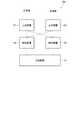
図1は、実施形態に係る電力変換システムを模式的に表すブロック図である。
図1に表したように、電力変換システム10は、主回路部12と、2つの制御装置14、16と、を備える。FIG. 1 is a block diagram schematically showing a power conversion system according to an embodiment.
As shown in FIG. 1, the
主回路部12は、交流電力から直流電力への変換及び直流電力から交流電力への変換の少なくとも一方を行う。主回路部12の構成は、上記の変換を行うことが可能な任意の構成でよい。 The
電力変換システム10は、例えば、直流電力で送電を行うことにより、2つの交流電力系統を連系させる直流送電システムや、周波数の異なる2つの交流電力系統を連系させる周波数変換システムなどに用いられる。 The
2つの制御装置14、16は、主回路部12の動作に関する制御を行う。2つの制御装置14、16は、例えば、主回路部12による電力の変換を制御する。2つの制御装置14、16は、一方が停止した場合にも他方で主回路部12の運転を継続できるようにする。これにより、例えば、制御装置14を修理などで停止させた場合にも、制御装置16によって主回路部12の運転を継続でき、電力変換システム10の動作安定性を高めることができる。 The two
2つの制御装置14、16は、例えば、主回路部12の一部の動作を制御する。制御装置14は、主回路部12の第1モジュールの動作を制御する。制御装置16は、主回路部12の第2モジュールの動作を制御する。制御装置14、16が正常に動作している場合には、第1モジュール及び第2モジュールの出力を等配分する。例えば、直流電力の目標値が300MWである場合、第1モジュール及び第2モジュールのそれぞれの直流電力を150MWとして制御を行う。制御装置14が動作を停止し、制御装置16のみで運転を継続する場合には、第1モジュールを休止させ、第2モジュールの直流電力を300MWとして制御を行う。これにより、一方が停止した場合にも他方で主回路部12の運転を継続することができる。但し、制御装置14、16は、それぞれが主回路部12の全体の動作を制御してもよい。制御装置14、16が正常に動作している場合には、制御装置14、16のいずれか一方の制御信号で主回路部12の動作を制御してもよい。 The two
図2は、実施形態に係る制御装置を模式的に表すブロック図である。
図2に表したように、2つの制御装置14、16は、指令値演算部20と、通信部22と、制御部24と、を有する。2つの制御装置14、16の構成は、実質的に同じである。FIG. 2 is a block diagram schematically showing the control device according to the embodiment.
As shown in FIG. 2, the two
2つの制御装置14、16には、主回路部12から供給する又は主回路部12に供給される直流電力の目標値が入力される。目標値は、例えば、上位装置(上位のコントローラ)などから制御装置14、16に入力される。目標値は、例えば、操作部などを介して手動で入力できるようにしてもよい。 The target values of the DC power supplied from the
指令値演算部20は、入力された直流電力の目標値と所定のレート速度とを基に、直流電力を目標値に近付けるための直流電力指令値を演算する。レート速度は、例えば、1MW/sである。指令値演算部20は、例えば、現在の直流電力指令値を所定のレート速度で目標値に近付けるように、直流電力指令値を演算する。指令値演算部20は、例えば、現在の直流電力指令値が100MWで、目標値が300MWで、レート速度が1MW/sである場合、101MWと直流電力指令値を演算し、その1秒後に102MWと演算する。このように、指令値演算部20は、所定のレート速度に基づいて直流電力指令値を順次更新する。 The command
制御装置14、16は、例えば、指令値演算部20によって演算された直流電力指令値を基に、主回路部12の動作を制御する。これにより、主回路部12から供給する又は主回路部12に供給される直流電力を目標値に近付けることができる。 The
通信部22は、通信を行うことにより、他方の制御装置14、16の直流電力指令値を取得可能とする。この例において、通信部22は、他方の制御装置14、16と通信を行うことにより、他方の制御装置14、16の直流電力指令値を他方の制御装置14、16から直接的に取得する。すなわち、制御装置14の通信部22は、制御装置16の通信部22と通信を行うことにより、制御装置16の直流電力指令値を制御装置16から直接的に取得する。同様に、制御装置16の通信部22は、制御装置14の通信部22と通信を行うことにより、制御装置14の直流電力指令値を制御装置14から直接的に取得する。 The
制御部24は、主回路部12の動作に関する制御を停止した状態から制御を行う状態に復帰する際に、通信部22を介して他方の制御装置14、16の直流電力指令値を取得する。電力変換システム10では、前述のように、制御装置14を修理などで停止させた場合にも、制御装置16によって主回路部12の運転を継続することができる。このように、システムとして電力供給を継続している状態(主回路部12が変換を行っている状態)での制御装置14又は制御装置16の復帰は、オンライン復旧などと呼ばれる場合もある。制御部24は、換言すれば、制御装置14、16のオンライン復旧の際に、通信部22を介して他方の制御装置14、16の直流電力指令値を取得する。 The
制御部24は、通信部22を介して他方の制御装置14、16の直流電力指令値を取得した後、指令値演算部20の演算する直流電力指令値を、他方の制御装置14、16の直流電力指令値に合わせ込む。すなわち、制御装置14の制御部24は、制御装置14のオンライン復旧の際に、通信部22を介して制御装置16の直流電力指令値を取得し、指令値演算部20の演算する直流電力指令値を、制御装置16の直流電力指令値に合わせ込む。同様に、制御装置16の制御部24は、制御装置16のオンライン復旧の際に、通信部22を介して制御装置14の直流電力指令値を取得し、指令値演算部20の演算する直流電力指令値を、制御装置14の直流電力指令値に合わせ込む。 The
また、制御部24は、オンライン復旧の処理を開始した後、復帰する制御装置の直流電流指令値が、健全な制御装置の直流電流指令値と一致した際に、オンライン復旧の処理が完了したと判断する。制御装置14、16は、オンライン復旧の処理が完了した後、通常の処理を開始する。 Further, the
図3は、実施形態に係る指令値演算部を模式的に表すブロック図である。
図3に表したように、指令値演算部20は、レート処理回路30と、リミッタ32と、を有する。レート処理回路30は、前述のように、直流電力の目標値と所定のレート速度とを基に、直流電力を目標値に近付けるための直流電力指令値を演算する。FIG. 3 is a block diagram schematically showing a command value calculation unit according to the embodiment.
As shown in FIG. 3, the command
リミッタ32は、レート処理回路30によって演算された直流電力指令値の上限値及び下限値を設定する。リミッタ32は、レート処理回路30によって演算された直流電力指令値が下限値よりも小さい場合に、直流電力指令値を下限値に制限する。また、リミッタ32は、レート処理回路30によって演算された直流電力指令値が上限値よりも大きい場合に、直流電力指令値を上限値に制限する。すなわち、リミッタ32は、直流電力指令値を下限値以上及び上限値以下の範囲に制限する。指令値演算部20は、リミッタ32を通過した後の直流電力指令値を、最終的な直流電力指令値として出力する。 The
この例において、指令値演算部20は、演算器34を有する。指令値演算部20には、リミッタ32の上下限値が入力される。指令値演算部20は、入力された上下限値をリミッタ32の上限値として設定するとともに、上下限値に演算器34で「−1」をかけたものをリミッタ32の下限値として設定する。リミッタ32の上限値及び下限値は、上記に限ることなく、例えば、上限値及び下限値を個別に設定してもよい。リミッタ32の上限値及び下限値は、制御装置14、16に設けられた操作部などを介して指令値演算部20に入力してもよいし、上位装置や下位装置などから指令値演算部20に入力してもよい。リミッタ32の上限値及び下限値は、予め決められた固定値でもよい。 In this example, the command
制御部24は、他方の制御装置14、16の直流電力指令値(健全系の直流電力指令値)を取得した後、リミッタ32の上限値及び下限値を他方の制御装置14、16の直流電力指令値に設定することにより、指令値演算部20の演算する直流電力指令値を、他方の制御装置14、16の直流電力指令値に合わせ込む。 After acquiring the DC power command value (healthy DC power command value) of the
指令値演算部20は、例えば、切替器36、38を有する。切替器36は、所定の上限値をリミッタ32の上限値に設定する状態と、他方の制御装置14、16の直流電力指令値をリミッタ32の上限値に設定する状態と、を切り替える。切替器38は、所定の下限値をリミッタ32の下限値に設定する状態と、他方の制御装置14、16の直流電力指令値をリミッタ32の下限値に設定する状態と、を切り替える。 The command
制御部24は、オンライン復旧の際に、復旧指令を指令値演算部20に入力する。制御部24から指令値演算部20への復旧指令の入力は、オンライン復旧の状態か否かを制御部24で判断し、オンライン復旧の状態と判断したことに応答して制御部24から指令値演算部20に自動的に入力してもよいし、制御装置14、16に設けられた操作部、上位装置、あるいは下位装置などから制御部24にオンライン復旧の処理の実行が指示されたことに応答して制御部24から指令値演算部20に入力してもよい。 The
復旧指令は、例えば、オンライン復旧の際にLowからHiに切り替わるパルス状の信号である。切替器36、38は、復旧指令が入力された際(復旧指令がHiになった際)に、他方の制御装置14、16の直流電力指令値をリミッタ32の下限値に設定する状態に切り替える。これにより、指令値演算部20の演算する直流電力指令値を、他方の制御装置14、16の直流電力指令値に合わせ込むことができる。 The recovery command is, for example, a pulse-like signal that switches from Low to Hi during online recovery. When the recovery command is input (when the recovery command becomes Hi), the
図4(a)及び図4(b)は、オンライン復旧時の直流電力指令値の時間変化の一例を模式的に表すグラフ図である。
図4(a)は、実施形態に係る制御装置14、16の動作の一例を模式的に表す。図4(b)は、直流電力指令値の合わせ込みを行わない参考の制御装置の動作の一例を模式的に表す。なお、ここでは、主回路部12の運転を継続する制御装置の直流電力指令値を健全系の直流電力指令値Pdp1、オンライン復旧を行う制御装置の直流電力指令値を復帰系の直流電力指令値Pdp2として説明を行う。4 (a) and 4 (b) are graphs schematically showing an example of a time change of the DC power command value at the time of online restoration.
FIG. 4A schematically shows an example of the operation of the
直流電力指令値のレート処理を行う制御装置において、直流電力指令値の合わせ込みを行わない場合には、図4(b)に表したように、各指令値Pdp1、Pdp2の差やレート速度などに応じて、復帰系の直流電力指令値Pdp2が、健全系の直流電力指令値Pdp1と一致するまでに時間がかかってしまう可能性がある。前述のように、制御装置14、16(制御部24)は、復帰系の直流電力指令値Pdp2が、健全系の直流電力指令値Pdp1と一致した際に、オンライン復旧が完了したと判断する。従って、この場合には、オンライン復旧が完了するまでに時間がかかってしまう。 When the DC power command value is not adjusted in the control device that performs the rate processing of the DC power command value, the difference between the command values Pdp1 and Pdp2, the rate speed, etc., as shown in FIG. 4 (b). Therefore, it may take time for the DC power command value Pdp2 of the return system to match the DC power command value Pdp1 of the sound system. As described above, the
これに対し、実施形態に係る制御装置14、16では、制御部24が、通信部22を介して健全系の直流電力指令値Pdp1を取得し、指令値演算部20の演算する復帰系の直流電力指令値Pdp2を、健全系の直流電力指令値Pdp1に合わせ込む。従って、図4(a)に表したように、オンライン復旧の開始の後、すぐに復帰系の直流電力指令値Pdp2を健全系の直流電力指令値Pdp1と一致させることができる。すなわち、オンライン復旧をすぐに完了させることができる。 On the other hand, in the
このように、本実施形態に係る電力変換システム10及び制御装置14、16では、2つの制御装置14、16の一方を停止させた状態から復帰させる場合に、より早期に復帰させることができる。 As described above, in the
図5は、実施形態に係る電力変換システムの変形例を模式的に表すブロック図である。 なお、上記実施形態と機能・構成上実質的に同じものについては、同符号を付し、詳細な説明は省略する。
図5に表したように、電力変換システム10aは、上位装置50をさらに備える。上位装置50は、2つの制御装置14、16に目標値を入力する。FIG. 5 is a block diagram schematically showing a modified example of the power conversion system according to the embodiment. The same reference numerals are given to those having substantially the same functions and configurations as those of the above-described embodiment, and detailed description thereof will be omitted.
As shown in FIG. 5, the
通信部22は、上位装置50と通信を行うことにより、他方の制御装置14、16の直流電力指令値を上位装置50を介して取得する。このように、健全系の直流電力指令値は、上位装置50を介して取得してもよい。この場合、通信部22は、必ずしも他方の制御装置14、16の通信部22と通信する機能を有していなくてもよい。 By communicating with the
図6は、実施形態に係る電力変換システムの変形例を模式的に表すブロック図である。 図6に表したように、電力変換システム10bは、2つの上位装置51、52をさらに備える。2つの上位装置51、52は、2つの制御装置14、16のそれぞれに目標値を入力する。 FIG. 6 is a block diagram schematically showing a modified example of the power conversion system according to the embodiment. As shown in FIG. 6, the
この場合、通信部22は、2つの上位装置51、52のいずれか一方と通信を行うことにより、他方の制御装置14、16の直流電力指令値をいずれか一方の上位装置51、52を介して取得する。このように、制御装置14、16に対して複数の上位装置が接続されている場合には、複数の上位装置のいずれかを介して健全系の直流電力指令値を取得してもよい。 In this case, the
図7は、実施形態に係る電力変換システムの変形例を模式的に表すブロック図である。 図7に表したように、電力変換システム10cでは、2つの上位装置51、52が、2つの制御装置14、16に個別に目標値を入力する。また、2つの上位装置51、52は、互いに通信を行う。 FIG. 7 is a block diagram schematically showing a modified example of the power conversion system according to the embodiment. As shown in FIG. 7, in the
この場合、通信部22は、他方の制御装置14、16の直流電力指令値を2つの上位装置51、52を介して取得する。このように、制御装置14、16のそれぞれに上位装置51、52が接続されている場合には、各上位装置51、52を介して健全系の直流電力指令値を取得してもよい。 In this case, the
図8は、実施形態に係る電力変換システムの変形例を模式的に表すブロック図である。 図8に表したように、電力変換システム10dは、下位装置60をさらに備える。下位装置60は、2つの制御装置14、16から入力される直流電力指令値を基に、主回路部12の動作に関する制御を行う。下位装置60は、例えば、直流電力指令値を基に、主回路部12の動作を制御する。但し、下位装置60の行う制御は、主回路部12の動作に関する任意の制御でよい。 FIG. 8 is a block diagram schematically showing a modified example of the power conversion system according to the embodiment. As shown in FIG. 8, the power conversion system 10d further includes a
通信部22は、下位装置60と通信を行うことにより、他方の制御装置14、16の直流電力指令値を下位装置60を介して取得する。このように、健全系の直流電力指令値は、下位装置60を介して取得してもよい。この場合も、通信部22は、必ずしも他方の制御装置14、16の通信部22と通信する機能を有していなくてもよい。 By communicating with the
図9は、実施形態に係る電力変換システムの変形例を模式的に表すブロック図である。 図9に表したように、電力変換システム10eは、2つの下位装置61、62をさらに備える。2つの下位装置61、62は、2つの制御装置14、16のそれぞれから入力される直流電力指令値を基に、主回路部12の動作に関する制御を行う。 FIG. 9 is a block diagram schematically showing a modified example of the power conversion system according to the embodiment. As shown in FIG. 9, the
この場合、通信部22は、2つの下位装置61、62のいずれか一方と通信を行うことにより、他方の制御装置14、16の直流電力指令値をいずれか一方の下位装置61、62を介して取得する。このように、制御装置14、16に対して複数の下位装置が接続されている場合には、複数の下位装置のいずれかを介して健全系の直流電力指令値を取得してもよい。 In this case, the
図10は、実施形態に係る電力変換システムの変形例を模式的に表すブロック図である。
図10に表したように、電力変換システム10fでは、2つの下位装置61、62が、2つの制御装置14、16のそれぞれに対応して設けられ、2つの制御装置14、16の一方から入力される直流電力指令値を基に、主回路部12の動作に関する制御を行う。また、2つの下位装置61、62は、互いに通信を行う。FIG. 10 is a block diagram schematically showing a modified example of the power conversion system according to the embodiment.
As shown in FIG. 10, in the
この場合、通信部22は、他方の制御装置14、16の直流電力指令値を2つの下位装置61、62を介して取得する。このように、制御装置14、16のそれぞれに下位装置61、62が接続されている場合には、各下位装置61、62を介して健全系の直流電力指令値を取得してもよい。 In this case, the
なお、上記各実施形態では、2つの制御装置14、16を備えた電力変換システムを表しているが、電力変換システムの備える制御装置の数は、2つに限ることなく、3つ以上でもよい。3つ以上の制御装置を備える場合にも、オンライン復旧の際に、健全系の直流電力指令値を取得し、復帰系の直流電力指令値を健全系の直流電力指令値に合わせ込むことで、上記と同様に、復帰系の制御装置を早期に復帰させ、オンライン復旧をすぐに完了させることができる。2つの制御装置14、16は、3つ以上の制御装置のうちの2つの制御装置でもよい。 Although each of the above embodiments represents a power conversion system including two
以上、本発明のいくつかの実施形態を説明したが、これらの実施形態は、例として提示したものであり、発明の範囲を限定することは意図していない。これら新規な実施形態は、その他のさまざまな形態で実施されることが可能であり、発明の要旨を逸脱しない範囲で、種々の省略、置き換え、変更を行うことができる。これら実施形態やその変形は、発明の範囲や要旨に含まれるとともに、特許請求の範囲に記載された発明およびその等価物の範囲に含まれる。また、前述の各実施形態は、相互に組み合わせて実施することができる。 Although some embodiments of the present invention have been described above, these embodiments are presented as examples and are not intended to limit the scope of the invention. These novel embodiments can be implemented in various other embodiments, and various omissions, replacements, and changes can be made without departing from the gist of the invention. These embodiments and modifications thereof are included in the scope and gist of the invention, and are also included in the scope of the invention and its equivalents described in the claims. Moreover, each of the above-described embodiments can be implemented in combination with each other.
10、10a〜10f 電力変換システム、 12 主回路部、 14 制御装置、 16 制御装置、 20 指令値演算部、 22 通信部、 24 制御部、 30 レート処理回路、 32 リミッタ、 34 演算器、 36 切替器、 38 切替器、 50、51、52 上位装置、 60、61、62 下位装置 10, 10a to 10f power conversion system, 12 main circuit unit, 14 control unit, 16 control unit, 20 command value calculation unit, 22 communication unit, 24 control unit, 30 rate processing circuit, 32 limiter, 34 arithmetic unit, 36 switching Instrument, 38 switch, 50, 51, 52 upper device, 60, 61, 62 lower device
Claims (10)
Translated fromJapanese前記主回路部の動作に関する制御を行い、一方が停止した場合にも他方で前記主回路部の運転を継続できるようにする2つの制御装置と、
を備え、
前記2つの制御装置は、
前記直流電力の目標値と所定のレート速度とを基に、前記直流電力を前記目標値に近付けるための直流電力指令値を演算する指令値演算部と、
通信を行うことにより、他方の前記制御装置の前記直流電力指令値を取得可能とする通信部と、
前記主回路部の動作に関する前記制御を停止した状態から前記制御を行う状態に復帰する際に、前記通信部を介して他方の前記制御装置の前記直流電力指令値を取得し、前記指令値演算部の演算する前記直流電力指令値を、他方の前記制御装置の前記直流電力指令値に合わせ込む制御部と、
を有する電力変換システム。A main circuit unit that performs at least one of conversion from AC power to DC power and conversion from DC power to AC power,
Two control devices that control the operation of the main circuit unit so that the operation of the main circuit unit can be continued even if one of them stops.
With
The two control devices are
A command value calculation unit that calculates a DC power command value for bringing the DC power closer to the target value based on the target value of the DC power and a predetermined rate and speed.
A communication unit capable of acquiring the DC power command value of the other control device by performing communication, and
When returning from the state in which the control regarding the operation of the main circuit unit is stopped to the state in which the control is performed, the DC power command value of the other control device is acquired via the communication unit, and the command value calculation is performed. A control unit that adjusts the DC power command value calculated by the unit to the DC power command value of the other control device.
Power conversion system with.
前記制御部は、他方の前記制御装置の前記直流電力指令値を取得した後、前記リミッタの前記上限値及び前記下限値を他方の前記制御装置の前記直流電力指令値に設定することにより、前記指令値演算部の演算する前記直流電力指令値を、他方の前記制御装置の前記直流電力指令値に合わせ込む請求項1記載の電力変換システム。The command value calculation unit has a limiter for setting an upper limit value and a lower limit value of the DC power command value.
After acquiring the DC power command value of the other control device, the control unit sets the upper limit value and the lower limit value of the limiter to the DC power command value of the other control device. The power conversion system according to claim 1, wherein the DC power command value calculated by the command value calculation unit is matched with the DC power command value of the other control device.
前記通信部は、前記上位装置と通信を行うことにより、他方の前記制御装置の前記直流電力指令値を前記上位装置を介して取得する請求項1又は2に記載の電力変換システム。The two control devices are further provided with a higher-level device for inputting the target value.
The power conversion system according to claim 1 or 2, wherein the communication unit acquires the DC power command value of the other control device via the higher-level device by communicating with the higher-level device.
前記通信部は、前記2つの上位装置のいずれか一方と通信を行うことにより、他方の前記制御装置の前記直流電力指令値をいずれか一方の前記上位装置を介して取得する請求項1又は2に記載の電力変換システム。Each of the two control devices is further provided with two higher-level devices for inputting the target value.
Claim 1 or 2 in which the communication unit communicates with one of the two higher-level devices to acquire the DC power command value of the other control device via the higher-level device. The power conversion system described in.
前記2つの上位装置は、互いに通信を行い、
前記通信部は、他方の前記制御装置の前記直流電力指令値を前記2つの上位装置を介して取得する請求項1又は2に記載の電力変換システム。Two higher-level devices for individually inputting the target values to the two control devices are further provided.
The two higher-level devices communicate with each other and
The power conversion system according to claim 1 or 2, wherein the communication unit acquires the DC power command value of the other control device via the two higher-level devices.
前記通信部は、前記下位装置と通信を行うことにより、他方の前記制御装置の前記直流電力指令値を前記下位装置を介して取得する請求項1又は2に記載の電力変換システム。A subordinate device that controls the operation of the main circuit unit based on the DC power command value input from the two control devices is further provided.
The power conversion system according to claim 1 or 2, wherein the communication unit acquires the DC power command value of the other control device via the lower device by communicating with the lower device.
前記通信部は、前記2つの下位装置のいずれか一方と通信を行うことにより、他方の前記制御装置の前記直流電力指令値をいずれか一方の前記下位装置を介して取得する請求項1又は2に記載の電力変換システム。It further includes two lower-level devices that control the operation of the main circuit unit based on the DC power command value input from each of the two control devices.
Claim 1 or 2 in which the communication unit acquires the DC power command value of the other control device via one of the lower devices by communicating with one of the two lower devices. The power conversion system described in.
前記2つの下位装置は、互いに通信を行い、
前記通信部は、他方の前記制御装置の前記直流電力指令値を前記2つの下位装置を介して取得する請求項1又は2に記載の電力変換システム。Two lower-level devices that are provided corresponding to each of the two control devices and that control the operation of the main circuit unit based on the DC power command value input from one of the two control devices are further added. Prepare,
The two subordinate devices communicate with each other and
The power conversion system according to claim 1 or 2, wherein the communication unit acquires the DC power command value of the other control device via the two lower devices.
前記主回路部の動作に関する制御を行い、一方が停止した場合にも他方で前記主回路部の運転を継続できるようにする2つの制御装置と、
を備えた電力変換システムに用いられる制御装置であって、
前記直流電力の目標値と所定のレート速度とを基に、前記直流電力を前記目標値に近付けるための直流電力指令値を演算する指令値演算部と、
通信を行うことにより、他方の前記制御装置の前記直流電力指令値を取得可能とする通信部と、
前記主回路部の動作に関する前記制御を停止した状態から前記制御を行う状態に復帰する際に、前記通信部を介して他方の前記制御装置の前記直流電力指令値を取得し、前記指令値演算部の演算する前記直流電力指令値を、他方の前記制御装置の前記直流電力指令値に合わせ込む制御部と、
を備えた制御装置。A main circuit unit that performs at least one of conversion from AC power to DC power and conversion from DC power to AC power,
Two control devices that control the operation of the main circuit unit so that the operation of the main circuit unit can be continued even if one of them stops.
It is a control device used in a power conversion system equipped with
A command value calculation unit that calculates a DC power command value for bringing the DC power closer to the target value based on the target value of the DC power and a predetermined rate and speed.
A communication unit capable of acquiring the DC power command value of the other control device by performing communication, and
When returning from the state in which the control regarding the operation of the main circuit unit is stopped to the state in which the control is performed, the DC power command value of the other control device is acquired via the communication unit, and the command value calculation is performed. A control unit that adjusts the DC power command value calculated by the unit to the DC power command value of the other control device.
Control device equipped with.
Priority Applications (1)
| Application Number | Priority Date | Filing Date | Title |
|---|---|---|---|
| JP2019229990AJP7189653B2 (en) | 2019-12-20 | 2019-12-20 | Power conversion system and controller |
Applications Claiming Priority (1)
| Application Number | Priority Date | Filing Date | Title |
|---|---|---|---|
| JP2019229990AJP7189653B2 (en) | 2019-12-20 | 2019-12-20 | Power conversion system and controller |
Publications (2)
| Publication Number | Publication Date |
|---|---|
| JP2021100301Atrue JP2021100301A (en) | 2021-07-01 |
| JP7189653B2 JP7189653B2 (en) | 2022-12-14 |
Family
ID=76541534
Family Applications (1)
| Application Number | Title | Priority Date | Filing Date |
|---|---|---|---|
| JP2019229990AActiveJP7189653B2 (en) | 2019-12-20 | 2019-12-20 | Power conversion system and controller |
Country Status (1)
| Country | Link |
|---|---|
| JP (1) | JP7189653B2 (en) |
Citations (4)
| Publication number | Priority date | Publication date | Assignee | Title |
|---|---|---|---|---|
| JPH06296396A (en)* | 1993-04-06 | 1994-10-21 | Hitachi Ltd | Induction motor speed control method and device |
| JPH08168252A (en)* | 1994-12-08 | 1996-06-25 | Mitsubishi Electric Corp | Control method of AC / DC converter |
| JP2008312273A (en)* | 2007-06-12 | 2008-12-25 | Toshiba Mitsubishi-Electric Industrial System Corp | Power converter |
| WO2019069394A1 (en)* | 2017-10-04 | 2019-04-11 | 三菱電機株式会社 | Power conversion apparatus |
- 2019
- 2019-12-20JPJP2019229990Apatent/JP7189653B2/enactiveActive
Patent Citations (4)
| Publication number | Priority date | Publication date | Assignee | Title |
|---|---|---|---|---|
| JPH06296396A (en)* | 1993-04-06 | 1994-10-21 | Hitachi Ltd | Induction motor speed control method and device |
| JPH08168252A (en)* | 1994-12-08 | 1996-06-25 | Mitsubishi Electric Corp | Control method of AC / DC converter |
| JP2008312273A (en)* | 2007-06-12 | 2008-12-25 | Toshiba Mitsubishi-Electric Industrial System Corp | Power converter |
| WO2019069394A1 (en)* | 2017-10-04 | 2019-04-11 | 三菱電機株式会社 | Power conversion apparatus |
Also Published As
| Publication number | Publication date |
|---|---|
| JP7189653B2 (en) | 2022-12-14 |
Similar Documents
| Publication | Publication Date | Title |
|---|---|---|
| US20200169205A1 (en) | Power conversion device and server | |
| CN102193151B (en) | Optical switch and optical-switch control method | |
| JP2016095586A (en) | Distributed control system, control device, control method, and program | |
| US20140132070A1 (en) | Rack and power control method thereof | |
| WO2018130105A1 (en) | Multi-core processor clock system, multi-core processor and control method therefor | |
| KR101748724B1 (en) | Apparatus for testing valve base electronics | |
| JP5922302B2 (en) | Distributed control system and control method | |
| TWI693770B (en) | Power load-sharing system | |
| CN106413165A (en) | Semiconductor microwave heating equipment, power control method thereof, and power control device thereof | |
| JP2021100301A (en) | Power conversion system and control device | |
| CN106507524B (en) | Semiconductor microwave heating equipment and its power control method and power control device | |
| KR102013778B1 (en) | Supervisory control and data acquisition system | |
| US9841747B2 (en) | Numerical control device for performing control axis switch | |
| CN105591573B (en) | The synchronisation control means and device of a kind of multi-machine system, a kind of multi-machine system | |
| JP7081452B2 (en) | Information processing device and control method of information processing device | |
| WO2016174476A3 (en) | Control of an electrical power network | |
| CN103048982A (en) | Automatic control system of technological equipment for integrated garbage treatment | |
| CN112462914B (en) | An integrated power supply structure | |
| CN104092208B (en) | The control method of a kind of DC transmission engineering bivalve sets in parallel operation and device | |
| RU2677390C1 (en) | Three-channel control system | |
| CN104315564B (en) | Microwave oven and microwave power adjustment method for microwave oven | |
| JP2018060289A (en) | Trajectory generation apparatus, control method, control program and recording medium for trajectory generation apparatus | |
| KR20170133984A (en) | Power supply device circuit having controlling function of stand-by power | |
| KR101792874B1 (en) | Dual control apparatus and method for HVDC system | |
| WO2020109752A1 (en) | A method relating to controllers of a vacuum pumping and/or abatement system |
Legal Events
| Date | Code | Title | Description |
|---|---|---|---|
| A621 | Written request for application examination | Free format text:JAPANESE INTERMEDIATE CODE: A621 Effective date:20220114 | |
| A977 | Report on retrieval | Free format text:JAPANESE INTERMEDIATE CODE: A971007 Effective date:20221128 | |
| TRDD | Decision of grant or rejection written | ||
| A01 | Written decision to grant a patent or to grant a registration (utility model) | Free format text:JAPANESE INTERMEDIATE CODE: A01 Effective date:20221201 | |
| A61 | First payment of annual fees (during grant procedure) | Free format text:JAPANESE INTERMEDIATE CODE: A61 Effective date:20221201 | |
| R150 | Certificate of patent or registration of utility model | Ref document number:7189653 Country of ref document:JP Free format text:JAPANESE INTERMEDIATE CODE: R150 |