JP2021091077A - Computer for video confirmation - Google Patents
Computer for video confirmationDownload PDFInfo
- Publication number
- JP2021091077A JP2021091077AJP2020099458AJP2020099458AJP2021091077AJP 2021091077 AJP2021091077 AJP 2021091077AJP 2020099458 AJP2020099458 AJP 2020099458AJP 2020099458 AJP2020099458 AJP 2020099458AJP 2021091077 AJP2021091077 AJP 2021091077A
- Authority
- JP
- Japan
- Prior art keywords
- area
- robot
- displayed
- computer
- video
- Prior art date
- Legal status (The legal status is an assumption and is not a legal conclusion. Google has not performed a legal analysis and makes no representation as to the accuracy of the status listed.)
- Granted
Links
Images


Classifications
- B—PERFORMING OPERATIONS; TRANSPORTING
- B25—HAND TOOLS; PORTABLE POWER-DRIVEN TOOLS; MANIPULATORS
- B25J—MANIPULATORS; CHAMBERS PROVIDED WITH MANIPULATION DEVICES
- B25J19/00—Accessories fitted to manipulators, e.g. for monitoring, for viewing; Safety devices combined with or specially adapted for use in connection with manipulators
- B25J19/06—Safety devices
- G—PHYSICS
- G06—COMPUTING OR CALCULATING; COUNTING
- G06T—IMAGE DATA PROCESSING OR GENERATION, IN GENERAL
- G06T7/00—Image analysis
- G06T7/0002—Inspection of images, e.g. flaw detection
- G06T7/0004—Industrial image inspection
- B—PERFORMING OPERATIONS; TRANSPORTING
- B25—HAND TOOLS; PORTABLE POWER-DRIVEN TOOLS; MANIPULATORS
- B25J—MANIPULATORS; CHAMBERS PROVIDED WITH MANIPULATION DEVICES
- B25J13/00—Controls for manipulators
- B25J13/08—Controls for manipulators by means of sensing devices, e.g. viewing or touching devices
- G—PHYSICS
- G05—CONTROLLING; REGULATING
- G05B—CONTROL OR REGULATING SYSTEMS IN GENERAL; FUNCTIONAL ELEMENTS OF SUCH SYSTEMS; MONITORING OR TESTING ARRANGEMENTS FOR SUCH SYSTEMS OR ELEMENTS
- G05B19/00—Programme-control systems
- G05B19/02—Programme-control systems electric
- G05B19/18—Numerical control [NC], i.e. automatically operating machines, in particular machine tools, e.g. in a manufacturing environment, so as to execute positioning, movement or co-ordinated operations by means of programme data in numerical form
- G05B19/406—Numerical control [NC], i.e. automatically operating machines, in particular machine tools, e.g. in a manufacturing environment, so as to execute positioning, movement or co-ordinated operations by means of programme data in numerical form characterised by monitoring or safety
- G05B19/4063—Monitoring general control system
- G—PHYSICS
- G06—COMPUTING OR CALCULATING; COUNTING
- G06F—ELECTRIC DIGITAL DATA PROCESSING
- G06F3/00—Input arrangements for transferring data to be processed into a form capable of being handled by the computer; Output arrangements for transferring data from processing unit to output unit, e.g. interface arrangements
- G06F3/01—Input arrangements or combined input and output arrangements for interaction between user and computer
- G06F3/048—Interaction techniques based on graphical user interfaces [GUI]
- G06F3/0481—Interaction techniques based on graphical user interfaces [GUI] based on specific properties of the displayed interaction object or a metaphor-based environment, e.g. interaction with desktop elements like windows or icons, or assisted by a cursor's changing behaviour or appearance
- G06F3/0482—Interaction with lists of selectable items, e.g. menus
- G—PHYSICS
- G06—COMPUTING OR CALCULATING; COUNTING
- G06F—ELECTRIC DIGITAL DATA PROCESSING
- G06F3/00—Input arrangements for transferring data to be processed into a form capable of being handled by the computer; Output arrangements for transferring data from processing unit to output unit, e.g. interface arrangements
- G06F3/01—Input arrangements or combined input and output arrangements for interaction between user and computer
- G06F3/048—Interaction techniques based on graphical user interfaces [GUI]
- G06F3/0484—Interaction techniques based on graphical user interfaces [GUI] for the control of specific functions or operations, e.g. selecting or manipulating an object, an image or a displayed text element, setting a parameter value or selecting a range
- G06F3/04847—Interaction techniques to control parameter settings, e.g. interaction with sliders or dials
- G—PHYSICS
- G06—COMPUTING OR CALCULATING; COUNTING
- G06T—IMAGE DATA PROCESSING OR GENERATION, IN GENERAL
- G06T11/00—2D [Two Dimensional] image generation
- G—PHYSICS
- G06—COMPUTING OR CALCULATING; COUNTING
- G06T—IMAGE DATA PROCESSING OR GENERATION, IN GENERAL
- G06T13/00—Animation
- G06T13/20—3D [Three Dimensional] animation
- G06T13/40—3D [Three Dimensional] animation of characters, e.g. humans, animals or virtual beings
- H—ELECTRICITY
- H01—ELECTRIC ELEMENTS
- H01L—SEMICONDUCTOR DEVICES NOT COVERED BY CLASS H10
- H01L21/00—Processes or apparatus adapted for the manufacture or treatment of semiconductor or solid state devices or of parts thereof
- H01L21/67—Apparatus specially adapted for handling semiconductor or electric solid state devices during manufacture or treatment thereof; Apparatus specially adapted for handling wafers during manufacture or treatment of semiconductor or electric solid state devices or components ; Apparatus not specifically provided for elsewhere
- H01L21/677—Apparatus specially adapted for handling semiconductor or electric solid state devices during manufacture or treatment thereof; Apparatus specially adapted for handling wafers during manufacture or treatment of semiconductor or electric solid state devices or components ; Apparatus not specifically provided for elsewhere for conveying, e.g. between different workstations
- G—PHYSICS
- G06—COMPUTING OR CALCULATING; COUNTING
- G06T—IMAGE DATA PROCESSING OR GENERATION, IN GENERAL
- G06T2207/00—Indexing scheme for image analysis or image enhancement
- G06T2207/30—Subject of image; Context of image processing
- G06T2207/30108—Industrial image inspection
- G06T2207/30148—Semiconductor; IC; Wafer
Landscapes
- Engineering & Computer Science (AREA)
- Physics & Mathematics (AREA)
- General Physics & Mathematics (AREA)
- Theoretical Computer Science (AREA)
- Human Computer Interaction (AREA)
- General Engineering & Computer Science (AREA)
- Manufacturing & Machinery (AREA)
- Mechanical Engineering (AREA)
- Robotics (AREA)
- Automation & Control Theory (AREA)
- Power Engineering (AREA)
- Microelectronics & Electronic Packaging (AREA)
- Computer Hardware Design (AREA)
- Condensed Matter Physics & Semiconductors (AREA)
- Quality & Reliability (AREA)
- Computer Vision & Pattern Recognition (AREA)
- Manipulator (AREA)
- Container, Conveyance, Adherence, Positioning, Of Wafer (AREA)
- Processing Or Creating Images (AREA)
- Numerical Control (AREA)
- Testing, Inspecting, Measuring Of Stereoscopic Televisions And Televisions (AREA)
Abstract
Translated fromJapaneseDescription
Translated fromJapanese本発明は、ロボットの動作に関する映像を確認するための映像確認用コンピュータに関する。 The present invention relates to a video confirmation computer for confirming a video relating to the operation of a robot.
従来から、例えば、ウエハ等の基板を搬送するためにロボットが用いられている。特許文献1のロボットは、ロボットの動きを制御するためのコントローラを備えている。 Conventionally, for example, a robot has been used to convey a substrate such as a wafer. The robot of
ロボットは、様々な原因でエラーを発生することがある。この場合、発生するエラーに応じてメンテナンス作業を行う必要がある。ウエハ処理設備等においては、高いレベルの情報管理を実現するため、別の場所へのデータの持出しや、外部ネットワークとの通信が制限される場合も多い。このような状況において、ロボットのエラーの原因を素早く特定して解消できることが求められている。 Robots can generate errors for a variety of reasons. In this case, it is necessary to perform maintenance work according to the error that occurs. In wafer processing equipment and the like, in order to realize a high level of information management, it is often the case that taking out data to another place and communication with an external network are restricted. In such a situation, it is required that the cause of the robot error can be quickly identified and eliminated.
本発明は以上の事情に鑑みてされたものであり、その目的は、例えばロボットのエラー発生時において、作業者が状況を素早く良好に把握可能とすることにある。 The present invention has been made in view of the above circumstances, and an object of the present invention is to enable an operator to quickly and satisfactorily grasp a situation, for example, when an error occurs in a robot.
本発明の解決しようとする課題は以上の如くであり、次にこの課題を解決するための手段とその効果を説明する。 The problem to be solved by the present invention is as described above, and next, the means for solving this problem and its effect will be described.
本発明の観点によれば、以下の構成の映像確認用コンピュータが提供される。即ち、この映像確認用コンピュータは、ロボットの動作に関する映像を確認するために用いられる。前記映像確認用コンピュータは、記憶部と、演算部と、を備える。前記記憶部は、情報を記憶可能である。前記演算部は、前記記憶部の記憶内容に基づく情報を出力する。前記記憶部は、電動モータの位置の情報と、映像の情報と、を記憶する。前記電動モータは、前記ロボットのリンク体を駆動する。前記電動モータの位置の情報は、前記ロボットのコントローラから受信される。前記映像の情報は、前記ロボットに取り付けたカメラにより取得される。前記演算部は、自機及び自機に接続されたコンピュータのうち少なくとも何れかに、モデル領域と、映像領域と、を並べて表示させる。前記モデル領域には、前記ロボットの姿勢を再現する2次元又は3次元のモデルが、コンピュータグラフィックスによって表示される。前記映像領域には、前記映像が表示される。 From the viewpoint of the present invention, a video confirmation computer having the following configuration is provided. That is, this image confirmation computer is used to confirm an image related to the operation of the robot. The video confirmation computer includes a storage unit and a calculation unit. The storage unit can store information. The calculation unit outputs information based on the stored contents of the storage unit. The storage unit stores information on the position of the electric motor and information on video. The electric motor drives the link body of the robot. Information on the position of the electric motor is received from the controller of the robot. The information of the video is acquired by a camera attached to the robot. The calculation unit causes at least one of the own machine and a computer connected to the own machine to display the model area and the video area side by side. In the model area, a two-dimensional or three-dimensional model that reproduces the posture of the robot is displayed by computer graphics. The image is displayed in the image area.
このように2つの領域が並べて表示されることで、作業者は、ロボットの動作に関する状況を複合的かつ直感的に把握することができる。従って、作業者は状況に対して、円滑かつ的確に対処することができる。 By displaying the two areas side by side in this way, the operator can grasp the situation regarding the operation of the robot in a complex and intuitive manner. Therefore, the worker can deal with the situation smoothly and accurately.
本発明によれば、例えばロボットのエラー発生時において、作業者が状況を素早く良好に把握することができる。 According to the present invention, for example, when an error occurs in a robot, an operator can quickly and well grasp the situation.
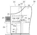
次に、図面を参照して本発明の実施の形態を説明する。図1は、本発明の一実施形態が適用される半導体処理設備20の一部を示す平面断面図である。図2は、半導体処理設備20の一部を切断して示す側面断面図である。図1及び図2には、ロボット27を様々に動かした状態が2点鎖線で示されている。 Next, an embodiment of the present invention will be described with reference to the drawings. FIG. 1 is a plan sectional view showing a part of a
半導体処理設備20は、処理対象基板となるウエハ24に対して、予め定められた処理を施す。本実施形態において、ウエハ24は、半導体ウエハである。ウエハ24に施される処理としては、例えば、熱処理、不純物導入処理、薄膜形成処理、リソグラフィ処理、洗浄処理又は平坦化処理等の様々なプロセス処理を挙げることができる。半導体処理設備20において、上述した基板処理以外の基板処理が行われてもよい。 The
半導体処理設備20は、ウエハ処理装置22と、ウエハ移載装置23と、を備える。半導体処理設備20は、例えばSEMI規格によって予め規定されたものである。SEMIは、Semiconductor Equipment and Materials Internationalの略称である。この場合、例えばフープ25及びフープ25を開閉するためのフープオープナ26は、SEMI規格のE47.1、E15.1、E57、E62、E63、E84等の仕様に従う。ただし、半導体処理設備20の構成がSEMI規格と異なっていても良い。 The
ウエハ処理装置22には、所定の気体が充填される処理空間30が形成されている。ウエハ処理装置22は、この処理空間30において、上述の処理をウエハ24に施す。ウエハ処理装置22は、ウエハ24に処理を施す処理装置本体のほか、処理空間30を形成する処理空間形成部と、処理空間30でウエハ24を搬送する搬送装置と、処理空間30に満たされる雰囲気気体を制御する調整装置と、を備える。調整装置は、ファンフィルタユニット等によって実現される。 The
ウエハ移載装置23は、処理前のウエハ24をフープ25から取り出してウエハ処理装置22に供給するとともに、処理後のウエハ24をウエハ処理装置22から取り出してフープ25に再収容する。ウエハ移載装置23は、フロントエンドモジュール装置(Equipment Front End Module;EFEM)として機能する。半導体処理設備20において、ウエハ移載装置23は、フープ25とウエハ処理装置22との間でのウエハ24の受渡しを行うインタフェース部となる。ウエハ24は、フープ25内の空間と、ウエハ処理装置22の処理空間30との間を移動する間に、予め定められる雰囲気気体で満たされるクリーン度の高い準備空間29を通過する。 The
準備空間29は、コンタミネーションコントロールが行われている閉じられた空間である。準備空間29では、空気中における浮遊微小粒子が限定された清浄度レベル以下に管理されており、必要に応じて温度、湿度、圧力等の環境条件についても管理が行われている。本実施形態では、処理空間30及び準備空間29は、ウエハ24の処理に悪影響を与えないように、所定のクリーン度に保たれる。このクリーン度としては、例えば、ISO(国際標準化機構)に規定されるCLASS1が採用される。 The
ロボット27は、ウエハ移載ロボットとして機能する。本実施形態では、ロボット27は、SCARA(スカラ)型の水平多関節ロボットによって実現される。SCARAは、Selective Compliance Assembly Robot Armの略称である。ロボット27は、準備空間29に配置される。 The
ロボット27は、図2等に示すように、基台41と、ロボットアーム42と、上下駆動アクチュエータ43aと、水平駆動アクチュエータ43bと、コントローラ44と、を備える。 As shown in FIG. 2 and the like, the
基台41は、ロボットアーム42を支持するベース部材として機能する。基台41の上面にロボットアーム42が取り付けられている。 The
ロボットアーム42は、基端部から先端部に向かう方向に順次連結される複数のリンク体を備えるリンク構造を有する。ロボットアーム42の先端部には、ロボットハンド45が設けられる。ロボットハンド45は、ウエハ24を保持したり、保持を解除したりすることができる。ロボットハンド45によるウエハ24の保持の方法は様々であり、例えば、ロボットハンド45の上にウエハ24を載せたり、ロボットハンド45によってウエハ24を挟んだり、負圧によってウエハ24をロボットハンド45に吸着したりすること等が考えられる。 The
上下駆動アクチュエータ43aは、ロボットアーム42を上下方向に変位させる。上下駆動アクチュエータ43aは、例えば電動モータとして構成される。ロボットアーム42が上下方向に移動することで、ロボットハンド45の高さを変更することができる。 The
水平駆動アクチュエータ43bは、ロボットアーム42の各リンク体を、対応する関節軸を中心として個別に回転させる。水平駆動アクチュエータ43bは、例えば電動モータとして構成される。上下方向の関節軸を中心として各リンク体が回転することで、ロボットハンド45を水平面内で移動させることができる。 The
コントローラ44は、予め定められる動作プログラム又はユーザから入力される移動指令に従って、上下駆動アクチュエータ43a及び水平駆動アクチュエータ43bを制御し、予め定められる位置にロボットハンド45を移動させる。コントローラ44は、図3に示すように、記憶回路46と、演算回路47と、出力装置48と、を備える。記憶回路46は、所定のプログラム及び各種のデータを記憶する。演算回路47は、前記プログラムに従って演算処理を行う。出力装置48は、演算回路47の演算結果に基づいて、上下駆動アクチュエータ43a及び水平駆動アクチュエータ43bに制御信号を出力する。記憶回路46は、例えば、RAM、ROM、及びHDD等によって実現される。演算回路47は、例えば、CPUによって実現される。 The
図3に示すように、半導体処理設備20は、上位コントローラ61を備える。上位コントローラ61は、半導体処理設備20を構成する様々な装置に、半導体処理工程を実行するための指令を送信する。 As shown in FIG. 3, the
上位コントローラ61は、ロボット27が備える前述のコントローラ44と有線又は無線で接続されている。上位コントローラ61は、ロボット27が必要なタイミングで必要な動作を行うように、コントローラ44に指令を送信する。コントローラ44は、上位コントローラ61から受信した指令に従って、ロボット27を制御する。 The
コントローラ44は、何らかのエラーが発生した場合、当該エラーに関する情報を上位コントローラ61に送信する。コントローラ44がロボット27を制御するためのプログラムは、複数のモジュールで構成されている。ここでモジュールとは、ロボット27によってある動作単位を実現するためのプログラムの部分をいう。動作単位としては、例えば、ロボットハンド45によって保持されているウエハ24を所定位置に載置する動作、及び、所定位置に載置されているウエハ24をロボットハンド45によって保持する動作等が挙げられるが、これに限定されない。 When an error occurs, the
上下駆動アクチュエータ43a及び水平駆動アクチュエータ43bは、それぞれ電動モータとして構成される。電動モータは公知の構成であり、図示しないが、モータ駆動回路と、モータ本体と、回転位置センサと、電流センサと、を備える。モータ本体は、ステータ、ロータ及び出力軸を備える。コントローラ44は、電動モータが所望の動作を行うように、電源回路を介してモータ駆動回路に電流を供給する。この結果、流れた電流に応じて電動モータの出力軸が回転する。 The
モータ駆動回路に流れる電流は、電動モータの動作の目標値と、動作の計測値と、によって決定される。電動モータの動作の目標値としては、例えば、回転位置、回転速度、又は回転加速度に関する目標値を挙げることができる。計測値としては同様に、例えば、回転位置、回転速度、又は回転加速度に関する計測値を挙げることができる。モータ駆動回路に流れる電流の制御において、フィードバック制御則又は適応制御則等の制御則が用いられても良い。 The current flowing through the motor drive circuit is determined by the target value of the operation of the electric motor and the measured value of the operation. As the target value of the operation of the electric motor, for example, a target value related to a rotation position, a rotation speed, or a rotation acceleration can be mentioned. Similarly, as the measured value, for example, a measured value relating to a rotational position, a rotational speed, or a rotational acceleration can be mentioned. In controlling the current flowing through the motor drive circuit, a control law such as a feedback control law or an adaptive control law may be used.
ロボットアーム42のうちロボットハンド45が固定されるリンク体には、カメラ62が固定されている。図3に示すように、このカメラ62は、映像確認用コンピュータ65にネットワークを介して接続されている。映像確認用コンピュータ65は、例えば、モバイル端末、パーソナルコンピュータ等とすることができる。 The
半導体処理設備20には、ロボット27を撮影するためのカメラ63が設けられている。カメラ63は、コントローラ44と有線又は無線で接続されている。 The
ロボット27に何らかの異常が発生し、トラブルシューティングの必要が生じた場合、作業者は何らかのコンピュータを操作して、対処のための情報を得ることができる。このコンピュータを、対処用コンピュータ70と呼ぶことがある。本実施形態では、上位コントローラ61が対処用コンピュータ70を兼ねている。 When some abnormality occurs in the
映像確認用コンピュータ65は、記憶回路(記憶部)66と演算回路(演算部)67とを含む。記憶回路66は、例えば、RAM、ROM及びHDD等によって実現される。演算回路67は、例えば、CPUによって実現される。 The
例えば以下の(1)〜(6)に示す情報が、映像確認用コンピュータ65の記憶回路66及びコントローラ44の記憶回路46(以下、単に記憶回路という)に記憶される。これらの記憶動作は、連続的に行われても良いし、間隔をあけて離散的に行われても良い。 For example, the information shown in the following (1) to (6) is stored in the
(1)カメラ62,63によって得られた画像に関する情報
(2)コントローラ44が上位コントローラ61から受信した信号、及び、コントローラ44が上位コントローラ61へ送信した信号に関する情報(通信ログ情報)
(3)コントローラ44がロボット27を制御するために実行したプログラムに関する情報
(4)ロボット27が備える電動モータの電流値、位置、速度、加速度(負の加速度を含む。以下同じ。)、位置偏差、速度偏差、及び加速度偏差に関する情報
(5)ロボット27が有する各種センサ(例えば、投光/遮光センサ、空気圧アクチュエータのピストン位置センサ、圧力センサ、ソレノイドバルブのバルブ位置センサ)からの出力信号に関する情報
(6)ロボット27が有する各種機器(例えば、ソレノイドバルブ)への入力信号に関する情報(1) Information about images obtained by the
(3) Information about the program executed by the
ここで、電動モータの電流値は、モータ駆動回路に設けられた電流センサによって計測される。電動モータの位置は、当該電動モータに設けられた回転位置センサの測定値に基づいて得ることができる。電動モータの速度及び加速度は、前記回転位置センサの測定値を時間微分することにより得ることができる。位置偏差、速度偏差、及び加速度偏差は、上述の位置、速度及び加速度と目標位置、目標速度、目標加速度との差を計算することにより得ることができる。 Here, the current value of the electric motor is measured by a current sensor provided in the motor drive circuit. The position of the electric motor can be obtained based on the measured value of the rotation position sensor provided in the electric motor. The speed and acceleration of the electric motor can be obtained by time-differentiating the measured values of the rotational position sensor. The position deviation, velocity deviation, and acceleration deviation can be obtained by calculating the difference between the above-mentioned position, velocity, and acceleration and the target position, target speed, and target acceleration.
コントローラ44には、ウェブサーバアプリケーション及びデータベースアプリケーションが予めインストールされ、プログラムが上述の記憶回路46に記憶されている。 A web server application and a database application are pre-installed in the
ところで、何らかの原因で、ロボット27にエラーが発生することがある。この場合、映像確認用コンピュータ65は、記憶回路66に記憶した内容に基づいて、図4に示すような状況確認画面71を表示することができる。この状況確認画面71は、モデル領域72と、映像領域73と、ログ領域74と、グラフ領域75と、を含む。 By the way, an error may occur in the
モデル領域72には、ある時点でのロボット27の姿勢を再現する2次元及び3次元のモデルが、コンピュータグラフィックスによって表示される。表示されるモデルの姿勢は、記憶回路66に記憶されたモータの位置に基づいて計算される。モデル領域72の下部にはシークバー72aが配置され、このシークバー72aには、スライダ、再生ボタン、一時停止ボタン及び逆再生ボタンが配置されている。これにより、モデル領域72の表示においてロボット27の動作を再現させたり、ある時点で止めたりすることができる。現実のロボット27が例えばカメラ63から隠れて撮影不能の位置にある場合でも、オペレータは、モデル領域72の表示内容を参照することで、ロボット27がどのような姿勢だったかを容易に把握することができる。 In the
映像領域73には、カメラ62により取得され、記憶回路66に記憶された撮影画像が表示される。画像の再生位置は、前記シークバー72aによって指定することができる。従って、モデル領域72におけるモデル動作の再現と、映像領域73による動画の再生と、を同期させることができる。 In the
ログ領域74には、記憶回路66に記憶された通信ログが表示される。ログ領域74に、ロボット27を制御するために実行されたプログラムに関する情報が表示されても良い。 The communication log stored in the
グラフ領域75には、記憶回路66に記憶された電動モータの電流値や位置、速度、加速度、位置偏差、速度偏差、加速度偏差に関する情報が、それぞれ異なる色のグラフで表示される。図4に示される例では、各値を縦軸にとり、時刻を横軸にとった折れ線グラフが表示されている。グラフ領域75の各グラフには、縦の直線(時刻図形)が表示されている。この直線の位置は、モデル領域72及び映像領域73において表示されている時点の時刻に対応している。 In the
ロボット27において何らかのエラーが発生すると、エラー発生時点を含む所定の時間範囲(例えば、エラー発生時点の数秒前からエラー発生時点の数秒後まで)に記憶回路66に記憶された情報が、状況確認画面71への表示対象となる。 When an error occurs in the
シークバー72aにおいて再生ボタンが押されると、モデル領域72及び映像領域73において表示対象の情報が再生される。同様に、逆再生ボタンが押されると、表示対象の情報が逆再生される。一時停止ボタンが押されると、再生/逆再生が一時停止し、一時停止ボタンが再び押されると、一時停止が解除される。シークバー72aに、公知の早送り操作/巻戻し操作を行うためのボタンが含まれても良い。 When the play button is pressed on the seek
表示対象の情報が再生される場合、モデル領域72には再現されたロボット27の動きが表示され、映像領域73にはカメラ62による撮影画像が動的に表示される。再生時において、ログ領域74には通信ログが表示され、グラフ領域75にはグラフが表示される。ログ領域74においては、シークバー72aで指示された時刻におけるログ履歴が表示される。このログ履歴は、再生に同期して刻々と追記されていく。グラフ領域75においては、各グラフにおける前記時刻図形が、再生に同期して、横向きに移動する。 When the information to be displayed is reproduced, the reproduced movement of the
以上の構成により、作業者は、エラー発生時に映像確認用コンピュータ65を操作することで、エラーの原因を様々な観点から迅速に特定し、対処することが可能になる。 With the above configuration, the operator can quickly identify the cause of the error from various viewpoints and deal with it by operating the
上記の例では、エラー発生前後の所定の時間範囲において記憶回路66に記憶された情報を状況確認画面71への表示対象としている。これに代えて、エラー発生時にコントローラ44において実行されていた動作単位又はモジュールに関して記憶された情報を状況確認画面71への表示対象としても良い。 In the above example, the information stored in the
モデル領域72及び映像領域73は、互いに近接するように、同一の状況確認画面71において並べて配置されている。従って、2つの領域の情報により、作業者は、エラーが発生した状況を複合的かつ直感的に理解することができる。 The
モデル領域72からはロボット27の全体的な状況が得られ、映像領域73からはロボットハンド45の先端周辺の詳細な状況が得られる。このように、モデル領域72に表示される2次元又は3次元モデルの情報と、映像領域73に表示される撮影映像の情報とは、互いに補完的な関係となり得る。この意味でも、両映像が並んで表示されるのは有利である。 The overall situation of the
加えて、ログ領域74のログ履歴の追加は、モデル領域72及び映像領域73が表示している時刻と整合するタイミングで行われるので、作業者が状況の把握に混乱することがない。 In addition, since the log history of the
モデル領域72と映像領域73が隣接して配置されているので、作業者はモデル映像と撮影画像とを一体的な情報として把握し易くなる。従って、モデル領域72のシークバー72aによって映像領域73の映像が再生/停止したとしても、違和感が生じにくい構成とすることができる。 Since the
図4の例では、モデル領域72が左、映像領域73が右となるように配置されている。しかしながら、配置を左右逆にしても良い。また、モデル領域72と映像領域73とを上下に並べて配置しても良い。 In the example of FIG. 4, the
次に、コントローラ44が対処用コンピュータ70のディスプレイ(例えば、図3に示すディスプレイ68)に表示させることが可能なログ解析画面81について、図5を参照して説明する。 Next, the
ロボット27に何らかのエラーが発生した場合、その時点前後の通信内容を記述した通信ログは、エラー原因の特定等のために価値の高い情報である。しかしながら、通信ログは一般に、エラーとの関連性が高いものと低いものを含んでおり、エラーとの関連性が低いものが大部分を占める場合も多い。従って、エラーとの関連性が高いものが他に埋没し、発見が難しくなるおそれがある。 When an error occurs in the
そこで本実施形態では、コントローラ44が対処用コンピュータ70に出力するログ解析画面81において、通信ログの中でもエラーとの関連性が高いものを抽出して表示する機能を有している。これにより、エラーの原因特定及び対処が容易になる。対処用コンピュータ70は、コントローラ44に対する端末として機能する。 Therefore, in the present embodiment, the
具体的に説明すると、通信ログの各行には、通信の種類を示す通信コードが記述される。コントローラ44の記憶回路46には、通信ログの中でエラーと関連性の高い通信コードの情報が、エラーの種類を特定する情報(例えば、エラーコード)と関連付けた形で予め記憶されている。通信ログの抽出が作業者によって指示された場合、エラーコードと関連性が高い種類の通信ログだけを表示するようにフィルタされ、コントローラ44から対処用コンピュータ70に出力される。 Specifically, a communication code indicating the type of communication is described in each line of the communication log. In the
コントローラ44は、このように絞り込まれた形で通信ログを対処用コンピュータ70に表示させる場合に、例えば以下の(1)〜(5)のような情報をまとめて同時に表示させることができる。このログ解析画面81により、作業者が状況をより容易に理解することができる。 When the communication log is displayed on the coping
(1)エラー説明領域82。エラー説明領域82の表示内容には、例えば、エラーの発生日時、エラーコード、及びエラーの概要が含まれる。
(2)詳細ログ領域83。詳細ログ領域83の表示内容には、上記のように抽出された、エラー発生の所定時間前からエラー発生時点までの通信ログが含まれる。
(3)動作位置領域84。動作位置領域84には、エラー発生時のロボット27の姿勢を示す数値を、電動モータにおいて計測された位置又は目標値の形で表示することができる。
(4)プログラム状態領域85。プログラム状態領域85には、詳細ログ領域83に表示された通信ログに応じてロボット27を制御するために実行されたモジュールを特定するための情報が表示される。ただし、詳細ログ領域83において通信ログの各行が選択可能となっており、選択された行のログに応じたプログラムがプログラム状態領域85に表示されても良い。
(5)入出力シグナル領域86。入出力シグナル領域86は、ロボット27が有する各種センサからの出力信号、及び、各種機器への入力信号が表示される。(1)
(2)
(3)
(4)
(5) Input /
次に、対処用コンピュータ70が表示可能なエラー対処支援画面88について、図6を参照して説明する。 Next, the error handling
コントローラ44の記憶回路46には、ロボット27に何らかのエラーが発生した場合の対処方法を示すデータが記憶されている。この対処方法をコントローラ44から対処用コンピュータ70に出力し、ディスプレイ(例えば、図3に示すディスプレイ68)に表示することにより、作業者のエラー対応を支援することができる。 The
エラーに対処する作業を支援するためにディスプレイ68に表示される内容としては、例えば以下の(1)〜(3)とすることができる。 The contents displayed on the
(1)エラー説明領域89。エラー説明領域89には、エラーの発生日時及びエラーコード等が表示される。エラー説明領域89においては、直近のエラー発生時点から過去の所定時間内に発生したエラー、又は、直近のエラー発生時点から過去の所定回数発生したエラーが、選択可能に表示されても良い。以下では、エラー説明領域89に表示された過去のエラーをエラー履歴と呼ぶことがある。 (1) Error explanation area 89. In the error explanation area 89, the date and time when the error occurred, the error code, and the like are displayed. In the error explanation area 89, an error that has occurred within a predetermined time in the past from the time when the latest error occurred, or an error that has occurred a predetermined number of times in the past from the time when the latest error has occurred may be displayed in a selectable manner. In the following, the past error displayed in the error explanation area 89 may be referred to as an error history.
(2)対処内容説明領域(詳細説明領域)90。対処内容説明領域90には、エラー説明領域89で説明対象となっているエラーに対応した対処方法が詳細に表示される。対処方法は、予めロボット27のメーカによってエラーコードに対応して作成され、HTMLデータ、画像データ、動画データ、PDFデータ等の適宜の電子データの形で、コントローラ44の記憶回路46に記憶される。エラー説明領域89でエラー履歴が選択された場合、対処内容説明領域90において、当該エラー履歴に対応した対処方法が表示されても良い。動画データは、例えば、過去にエラーが発生したときにロボット27をカメラ63で撮影したデータとすることができる。 (2) Action content explanation area (detailed explanation area) 90. In the action
(3)関連項目一覧領域91。関連項目一覧領域91には、エラー説明領域89で説明対象となっているエラーに関連する項目の一覧が表示される。エラー説明領域89でエラー履歴が選択された場合、関連項目一覧領域91において、当該エラー履歴に関連する項目が表示されても良い。一覧は、1又は複数の関連項目から構成される。関連項目としては、例えば、以下の(a),(b)とすることができる。
(a)今回のエラー又は選択されたエラー履歴に対して過去に対応した作業記録。作業者は、エラーが発生した場合に適宜のユーザインタフェース装置を操作することで、作業記録作成画面をディスプレイ68に表示させることができる。このインタフェースは、例えば、ディスプレイ68と一体的に設けられたタッチパネル、又は、ディスプレイ68の近傍に配置されるハードウェアキー等とすることができるが、これに限定されない。作業記録作成画面で、作業者は、エラーコード、エラー発生日時、作業日時、作業者、作業内容とその結果、作業記録の標題、作業記録の重要度等を指定して、作業記録を作成することができる。作業者が対処用コンピュータ70に入力した作業記録は、対処用コンピュータ70からコントローラ44に送信される。作業記録のデータを受信したコントローラ44は、エラーコードに関連付けて、当該作業記録を記憶回路46に記憶する。関連項目一覧領域91には、例えば、作業記録の重要度と標題が表示される。
(b)今回のエラー又は選択されたエラー履歴に関連するエラー。関連するエラーとしては、例えば、あるエラーと同時に発生する可能性がある他のエラー、及び、あるエラーの発生に起因して発生する他のエラーが挙げられるが、これに限定されない。エラーとエラーの関連付けは、ロボット27のメーカによって予め作成され、コントローラ44の記憶回路46に記憶される。エラーとエラーの関連は、作業者の操作によって記憶回路46に登録可能に構成されても良い。関連項目一覧領域91には、例えば、エラーコードが表示される。(3) Related
(A) Work record corresponding to the past for this error or the selected error history. When an error occurs, the operator can display the work record creation screen on the
(B) This error or an error related to the selected error history. Related errors include, but are not limited to, for example, other errors that may occur at the same time as one error, and other errors that occur as a result of the occurrence of one error. The error-to-error association is created in advance by the manufacturer of the
作業者は、上述のユーザインタフェース装置を適宜操作することにより、関連項目一覧領域91において表示されている関連項目を適宜選択することができる。選択された関連項目の情報は、対処用コンピュータ70からコントローラ44へ送信される。コントローラ44は、作業記録が選択された場合は当該作業記録の内容を、関連するエラーが選択された場合は当該エラーの対処方法を、それぞれ対処内容説明領域90に表示させるように、各種データを対処用コンピュータ70へ送信する。 The operator can appropriately select the related items displayed in the related
関連項目一覧領域91には複数の関連項目を表示することができるが、コントローラ44は、優先度が高い関連項目が上、優先度が低い関連項目が下となるように、関連項目をソートして表示するように対処用コンピュータ70を制御することができる。図6には、関連項目一覧領域91において優先度に応じて関連項目が並べられた状態が示されている。優先度は、例えば、エラーの発生頻度、説明画面が表示された頻度、作業記録において指定された重要度、エラー発生時の電流センサ、位置センサ検出値から判断した関連度等に基づいて決定することができる。優先度を定めるために複数の観点が用いられる場合、コントローラ44は、例えば、エラーの発生頻度等を数値化した指標に適宜の重みを乗じたものの総和を計算し、得られた総和を優先度とすることができる。 A plurality of related items can be displayed in the related
例えば衝突が発生した場合には、各関節を駆動する複数のモータについて同時に位置偏差の増大等の異常が検知される。一方、例えばあるモータのケーブルが断線した場合には当該モータのみについて異常が検知される。このように想定される異常検知パターンを予め記憶しておき、異常が発生した際に実際の異常検知パターンと想定異常検知パターンとの類似度を計算し、類似度の高い想定異常検知パターンに対応する異常に対するトラブルシューティング内容を優先的に表示するようにしても良い。異常検知パターンとして、複数の検知項目(位置偏差や速度偏差等)の発生/不発生の組み合わせを用いても良く、異常発生時のあるモータの電流値等の計測値を用いても良い。また、類似度としては、例えば複数の検知項目の発生/不発生の組み合わせを異常検知パターンとして用いる場合には、複数の検知項目の発生/不発生の組み合わせが一致する数を用いても良い。この場合、複数の検知項目に重み付けをすることで重要な検知項目の類似度に与える影響を大きくしても良い。 For example, when a collision occurs, an abnormality such as an increase in position deviation is detected at the same time for a plurality of motors driving each joint. On the other hand, for example, when the cable of a certain motor is broken, an abnormality is detected only in the motor. The assumed abnormality detection pattern is stored in advance in this way, and when an abnormality occurs, the degree of similarity between the actual abnormality detection pattern and the assumed abnormality detection pattern is calculated, and the assumed abnormality detection pattern with a high degree of similarity is supported. It is also possible to preferentially display the troubleshooting contents for the abnormalities to be performed. As the abnormality detection pattern, a combination of occurrence / non-occurrence of a plurality of detection items (positional deviation, speed deviation, etc.) may be used, or a measured value such as a current value of a motor at the time of abnormality occurrence may be used. As the degree of similarity, for example, when a combination of occurrence / non-occurrence of a plurality of detection items is used as an abnormality detection pattern, a number in which the combinations of occurrence / non-occurrence of a plurality of detection items match may be used. In this case, weighting a plurality of detection items may increase the influence on the similarity of important detection items.
以上の構成とすることにより、エラーの原因の特定と対処が容易になる。また、ユーザによって登録された作業記録もエラー対処支援画面88における表示対象とすることで、過去の対処によって獲得された知識の蓄積に基づく対処が可能になり、また、そのような知識を複数人で共有することができる。関連項目は優先度が高いものから順に表示されるので、発生したエラーに対して効率的に対処することができる。 With the above configuration, it becomes easy to identify the cause of the error and deal with it. In addition, by displaying the work record registered by the user on the error handling
コントローラ44の記憶回路46には、エラーの原因を特定するための方法、エラーの対処方法が記述された資料、及び、ロボットの使用方法が記述されたマニュアルが記憶されている。ユーザは、状況に応じてユーザインタフェース装置を操作することにより、図7に示すように、これらの資料及びマニュアルをディスプレイ68に表示させて参照することができる。 The
マニュアル画面93を簡単に説明する。マニュアル画面93の左側には目次表示領域94が配置され、この目次表示領域94には、マニュアルの目次の項目が一覧形式で表示されている。マニュアル画面93の右側には詳細表示領域95が配置され、この詳細表示領域95には、目次表示領域94で選択された目次の項目に対応するマニュアルの具体的な内容を表示することができる。目次表示領域94の上側には検索ボックス96が配置されており、マニュアルのテキストデータを対象とするテキスト検索を行うことができる。これにより、紙のマニュアルをロボット27の近くまで持ち込むことが不要になる。 The
以上に説明したログ解析画面81、エラー対処支援画面88、及びマニュアル画面93のそれぞれの表示は、コントローラ44に予めインストールされているウェブサーバアプリケーションと、対処用コンピュータ70に予めインストールされているWebブラウザアプリケーションと、の連携により実現される。対処用コンピュータ70において作業者がウェブブラウザを起動して適宜操作することにより、上述のログ解析画面81、エラー対処支援画面88、マニュアル画面93を、ウェブページ等の形で例えばディスプレイ68に表示することができる。 The displays of the
各種画面を閲覧するための対処用コンピュータ70(言い換えれば、コントローラ44に対する端末)は、上位コントローラ61とは別に用意されても良い。何れにせよ、閲覧側のコンピュータには、ウェブブラウザアプリケーションがインストールされる。コントローラ44のウェブサーバは、閲覧側のコンピュータのウェブブラウザからの要求に応じて、記憶回路46の記憶内容から表示内容を決定し、HTMLデータ等の各種データを送信する。閲覧側のコンピュータにおいてウェブブラウザは、受信した各種データに基づいて、ウェブページ等の画面を描画する。この構成では、作業者は、一般的なウェブブラウザアプリケーションがインストールされた適宜の端末を閲覧側のコンピュータとして準備するだけで、ログ解析画面81、エラー対処支援画面88、及びマニュアル画面93の機能を利用することができる。このように、本実施形態では、端末に専用アプリケーションのような特別なソフトをインストールする必要がない。従って、この構成は、一般的に電子機器の持込みが厳しく制限され、持ち込まれる電子機器に対して高度な機密保持対策が要求される半導体製造工場等において好適である。 The coping computer 70 (in other words, the terminal for the controller 44) for viewing various screens may be prepared separately from the
以上に説明したように、本実施形態において、ロボット27の動作に関する映像を確認するための映像確認用コンピュータ65は、記憶回路66と、演算回路67と、を備える。記憶回路66は、情報を記憶可能である。演算回路67は、記憶回路66の記憶内容に基づく情報を出力する。記憶回路66は、ロボット27のリンク体を駆動する電動モータの位置の情報と、映像の情報と、を記憶する。電動モータの位置の情報は、ロボット27のコントローラ44から受信される。映像の情報は、ロボット27に取り付けたカメラ62により取得される。演算回路67は、自機のディスプレイに、モデル領域72と、映像領域73と、を並べて表示させる。モデル領域72には、ロボット27の姿勢を再現する2次元又は3次元のモデルが、コンピュータグラフィックスによって表示される。映像領域73には、映像が表示される。 As described above, in the present embodiment, the
このように2つの領域が並べて表示されることで、作業者は、ロボット27の動作に関する状況を複合的かつ直感的に把握することができる。従って、作業者は状況(例えば、エラーの発生)に対して、円滑かつ的確に対処することができる。 By displaying the two areas side by side in this way, the operator can grasp the situation regarding the operation of the
また、本実施形態の映像確認用コンピュータ65において、モデル領域72に表示されるモデルに対応する時刻と、映像領域73に表示される映像に対応する時刻が、同期している。 Further, in the
これにより、モデル領域72におけるモデル動作の再現と、映像領域73による動画の再生と、を同期させることができる。従って、画面を見た作業者は、状況を容易に把握することができる。 As a result, the reproduction of the model operation in the
また、本実施形態の映像確認用コンピュータ65において、記憶回路66は、コントローラ44が他の装置と通信した通信ログを記憶する。演算回路67は、モデル領域72及び映像領域73に加えて、通信ログの履歴が出力されるログ領域74を、自機に表示させる。ログ領域74への通信ログ履歴の表示タイミングが、モデル領域72及び映像領域73における時刻に同期している。 Further, in the
これにより、ログ領域74の表示の変化が、モデル領域72及び映像領域73が表す時刻と整合するタイミングで行われる。従って、作業者が状況の把握に混乱することがない。 As a result, the change in the display of the
また、本実施形態の映像確認用コンピュータ65において、演算回路67は、モデル領域72に表示されるモデルに対応する時刻、及び、映像領域73に表示される映像に対応する時刻を指定するための共通のシークバー72aを表示させる。 Further, in the
これにより、シークバーを用いた直感的な操作によって、どの時刻での状況をモデル領域72及び映像領域73に表示させるかを指定することができる。従って、作業者が、知りたい時刻での状況を容易に把握することができる。また、シークバー72aが共通であるので、操作の際に混乱しにくい簡素な画面を実現できる。 Thereby, it is possible to specify at what time the situation is to be displayed in the
以上に本発明の好適な実施の形態を説明したが、上記の構成は例えば以下のように変更することができる。 Although the preferred embodiment of the present invention has been described above, the above configuration can be changed as follows, for example.
ロボット27の正常状態における情報を、映像確認用コンピュータ65の記憶回路66及びコントローラ44の記憶回路46のうち少なくとも何れかに記憶しても良い。この場合、エラーが発生したときは、映像確認用コンピュータ65又は対処用コンピュータ70において、正常状態での情報を参考のために表示することができる。この構成は、映像確認用コンピュータ65が表示する状況確認画面71におけるグラフ領域75において特に有利である。グラフ領域75のグラフは正常状態でも大きく変動することがあり、比較の基準がないと異常と正常の区別が難しいからである。正常状態におけるグラフの特徴を示すパラメータ(例えば、値の平均値、最大値、最小値等)を、グラフ領域75のグラフにおいて併せて表示することもできる。 Information in the normal state of the
ログ解析画面81、エラー対処支援画面88及びマニュアル画面93のうち少なくとも何れかを表示させるコンピュータは、ロボット27への教示作業を行うために操作されるティーチペンダントであっても良い。 The computer that displays at least one of the
ロボット27に取り付けられるカメラ62で取得された画像は、ティーチペンダントによって教示作業を行う際に補助的に用いることもできる。 The image acquired by the
映像確認用コンピュータ65と、対処用コンピュータ70とを、1つのハードウェア(コンピュータ)で実現しても良い。 The
映像確認用コンピュータ65が表示する状況確認画面71についても、ログ解析画面81等と同様に、ブラウザベースで表示されても良い。 The
映像確認用コンピュータ65は、状況確認画面71を、自機のディスプレイに代えて、又はそれに加えて、映像確認用コンピュータ65に接続された他のコンピュータのディスプレイに表示させても良い。 The
27 ロボット
44 コントローラ(ロボット用コントローラ)
65 映像確認用コンピュータ
66 記憶回路(記憶部)
67 演算回路(演算部)
68 ディスプレイ(表示部)
72 モデル領域
73 映像領域
74 ログ領域27
65
67 Arithmetic circuit (calculation unit)
68 Display (display unit)
72
Claims (4)
Translated fromJapanese情報を記憶可能な記憶部と、
前記記憶部の記憶内容に基づく情報を出力する演算部と、
を備え、
前記記憶部は、
前記ロボットのコントローラから受信した、前記ロボットのリンク体を駆動する電動モータの位置の情報と、
前記ロボットに取り付けたカメラにより取得された映像の情報と、
を記憶し、
前記演算部は、自機及び自機に接続されたコンピュータのうち少なくとも何れかに、
前記ロボットの姿勢を再現する2次元又は3次元のモデルが、コンピュータグラフィックスによって表示されるモデル領域と、
前記映像が表示される映像領域と、
を並べて表示させることを特徴とする映像確認用コンピュータ。It is a computer for checking images for checking images related to robot movements.
A storage unit that can store information and
An arithmetic unit that outputs information based on the stored contents of the storage unit, and
With
The storage unit
Information on the position of the electric motor that drives the link body of the robot received from the controller of the robot, and
The information of the image acquired by the camera attached to the robot and
Remember,
The arithmetic unit is used in at least one of the own machine and a computer connected to the own machine.
A two-dimensional or three-dimensional model that reproduces the posture of the robot is displayed in a model area displayed by computer graphics.
The video area where the video is displayed and
A computer for checking images, which is characterized by displaying images side by side.
前記モデル領域に表示される前記モデルに対応する時刻と、前記映像領域に表示される映像に対応する時刻が、同期していることを特徴とする映像確認用コンピュータ。The video confirmation computer according to claim 1.
An image confirmation computer characterized in that the time corresponding to the model displayed in the model area and the time corresponding to the image displayed in the image area are synchronized.
前記記憶部は、前記コントローラが他の装置と通信した通信ログを記憶し、
前記演算部は、前記モデル領域及び前記映像領域に加えて、前記通信ログの履歴が出力されるログ領域を、自機及び自機に接続されたコンピュータのうち少なくとも何れかに表示させ、
前記ログ領域への通信ログ履歴の表示タイミングが、前記モデル領域及び前記映像領域における時刻に同期していることを特徴とする映像確認用コンピュータ。The video confirmation computer according to claim 2.
The storage unit stores a communication log in which the controller communicates with another device, and stores the communication log.
In addition to the model area and the video area, the calculation unit displays a log area to which the history of the communication log is output on at least one of the own machine and a computer connected to the own machine.
A video confirmation computer characterized in that the display timing of the communication log history in the log area is synchronized with the time in the model area and the video area.
前記演算部は、前記モデル領域に表示される前記モデルに対応する時刻、及び、前記映像領域に表示される映像に対応する時刻を指定するための共通のシークバーを表示させることを特徴とする映像確認用コンピュータ。The video confirmation computer according to claim 2 or 3.
An image characterized by the calculation unit displaying a common seek bar for designating a time corresponding to the model displayed in the model area and a time corresponding to the image displayed in the image area. Confirmation computer.
Priority Applications (7)
| Application Number | Priority Date | Filing Date | Title |
|---|---|---|---|
| US17/783,297US12045972B2 (en) | 2019-12-10 | 2020-12-04 | Video confirmation computer |
| PCT/JP2020/045186WO2021117619A1 (en) | 2019-12-10 | 2020-12-04 | Video-confirming computer |
| CN202080085828.5ACN114830320B (en) | 2019-12-10 | 2020-12-04 | Image Confirmation Computer |
| KR1020227021747AKR20220100983A (en) | 2019-12-10 | 2020-12-04 | computer to check video |
| TW109143325ATWI770712B (en) | 2019-12-10 | 2020-12-09 | computer for image verification |
| US18/754,454US12406351B2 (en) | 2019-12-10 | 2024-06-26 | Video confirmation computer |
| JP2024190658AJP2025013387A (en) | 2019-12-10 | 2024-10-30 | Substrate transport system and substrate transport method |
Applications Claiming Priority (2)
| Application Number | Priority Date | Filing Date | Title |
|---|---|---|---|
| JP2019222900 | 2019-12-10 | ||
| JP2019222900 | 2019-12-10 |
Related Child Applications (1)
| Application Number | Title | Priority Date | Filing Date |
|---|---|---|---|
| JP2024190658ADivisionJP2025013387A (en) | 2019-12-10 | 2024-10-30 | Substrate transport system and substrate transport method |
Publications (2)
| Publication Number | Publication Date |
|---|---|
| JP2021091077Atrue JP2021091077A (en) | 2021-06-17 |
| JP7582797B2 JP7582797B2 (en) | 2024-11-13 |
Family
ID=76311372
Family Applications (3)
| Application Number | Title | Priority Date | Filing Date |
|---|---|---|---|
| JP2020099460APendingJP2021091078A (en) | 2019-12-10 | 2020-06-08 | Controller for robot |
| JP2020099458AActiveJP7582797B2 (en) | 2019-12-10 | 2020-06-08 | Computer for checking video images, display method and display program |
| JP2024190658APendingJP2025013387A (en) | 2019-12-10 | 2024-10-30 | Substrate transport system and substrate transport method |
Family Applications Before (1)
| Application Number | Title | Priority Date | Filing Date |
|---|---|---|---|
| JP2020099460APendingJP2021091078A (en) | 2019-12-10 | 2020-06-08 | Controller for robot |
Family Applications After (1)
| Application Number | Title | Priority Date | Filing Date |
|---|---|---|---|
| JP2024190658APendingJP2025013387A (en) | 2019-12-10 | 2024-10-30 | Substrate transport system and substrate transport method |
Country Status (6)
| Country | Link |
|---|---|
| US (2) | US12045972B2 (en) |
| JP (3) | JP2021091078A (en) |
| KR (1) | KR20220100983A (en) |
| CN (1) | CN114830320B (en) |
| TW (2) | TWI770712B (en) |
| WO (2) | WO2021117619A1 (en) |
Cited By (4)
| Publication number | Priority date | Publication date | Assignee | Title |
|---|---|---|---|---|
| CN114612597A (en)* | 2022-03-10 | 2022-06-10 | 江苏邑文微电子科技有限公司 | Animation simulation method and device, electronic equipment and storage medium |
| JP2022132166A (en)* | 2021-02-26 | 2022-09-07 | 株式会社キビテク | robot support system |
| WO2025143242A1 (en)* | 2023-12-28 | 2025-07-03 | 川崎重工業株式会社 | Robot system and control method for robot system |
| US12406351B2 (en) | 2019-12-10 | 2025-09-02 | Kawasaki Jukogyo Kabushiki Kaisha | Video confirmation computer |
Families Citing this family (7)
| Publication number | Priority date | Publication date | Assignee | Title |
|---|---|---|---|---|
| KR102694325B1 (en)* | 2021-12-21 | 2024-08-09 | 이규옥 | FOUP with end effector detection sensor and integrated data management system thereof |
| JP7668241B2 (en)* | 2022-02-28 | 2025-04-24 | 川崎重工業株式会社 | Information processing device |
| JP2023130799A (en)* | 2022-03-08 | 2023-09-21 | 株式会社デンソーウェーブ | Maintenance system of industrial robot |
| DE112022007671T5 (en)* | 2022-10-31 | 2025-07-24 | Fanuc Corporation | Device for creating a video instruction and method for creating a video instruction |
| KR102624242B1 (en)* | 2023-07-07 | 2024-01-15 | 주식회사 아임토리 | System for providing two dimensional and three dimensional matching service for robot |
| JP7723144B1 (en)* | 2024-05-22 | 2025-08-13 | 川崎重工業株式会社 | Robot System |
| JP7668407B1 (en)* | 2024-05-22 | 2025-04-24 | 川崎重工業株式会社 | Substrate Transfer System |
Citations (6)
| Publication number | Priority date | Publication date | Assignee | Title |
|---|---|---|---|---|
| JP2001062766A (en)* | 1999-08-26 | 2001-03-13 | Matsushita Electric Works Ltd | User interface system for remote control of bipedal walking robot |
| JP2004174662A (en)* | 2002-11-27 | 2004-06-24 | Fanuc Ltd | Operation state analysis device for robot |
| JP2006120820A (en)* | 2004-10-21 | 2006-05-11 | Hitachi Sci Syst Ltd | Thin substrate processing apparatus and thin substrate transfer apparatus |
| JP2009214265A (en)* | 2008-03-12 | 2009-09-24 | Denso Wave Inc | Robot teaching apparatus |
| JP2017052053A (en)* | 2015-09-10 | 2017-03-16 | 株式会社Ihiエアロスペース | Method of creating image for remote-control in unmanned vehicle, and remote control system of unmanned vehicle |
| JP2019171490A (en)* | 2018-03-27 | 2019-10-10 | 日本電産サンキョー株式会社 | Operation history management system |
Family Cites Families (25)
| Publication number | Priority date | Publication date | Assignee | Title |
|---|---|---|---|---|
| JP2764586B2 (en)* | 1988-09-30 | 1998-06-11 | トーヨーエイテック株式会社 | Machine abnormality recovery method display device |
| JPH03105406A (en)* | 1989-09-19 | 1991-05-02 | Matsushita Electric Ind Co Ltd | How to display equipment error messages |
| US20030045098A1 (en)* | 2001-08-31 | 2003-03-06 | Applied Materials, Inc. | Method and apparatus for processing a wafer |
| JP2004031381A (en) | 2002-06-21 | 2004-01-29 | Hitachi High-Technologies Corp | Semiconductor manufacturing apparatus, diagnostic apparatus therefor, and operation system of semiconductor manufacturing apparatus |
| JP4617302B2 (en) | 2004-03-22 | 2011-01-26 | 株式会社デジタル | Display, program product for causing computer to function as display, and recording medium storing program product |
| JP2006219258A (en)* | 2005-02-10 | 2006-08-24 | Hitachi Plant Technologies Ltd | Work support system for equipment |
| KR20070069802A (en)* | 2005-12-28 | 2007-07-03 | 엘지.필립스 엘시디 주식회사 | Manufacturing apparatus of flat panel display device and substrate damage prevention method using same |
| JP4098338B2 (en) | 2006-07-20 | 2008-06-11 | 川崎重工業株式会社 | Wafer transfer device and substrate transfer device |
| JP5260156B2 (en)* | 2008-06-17 | 2013-08-14 | 株式会社日立ハイテクノロジーズ | Automatic analyzer management system |
| JP5184329B2 (en)* | 2008-12-22 | 2013-04-17 | 株式会社日立国際電気 | Substrate processing apparatus, substrate processing method, and semiconductor device manufacturing method |
| JP5414703B2 (en)* | 2011-01-20 | 2014-02-12 | 東京エレクトロン株式会社 | Abnormality diagnosis method for processing apparatus and abnormality diagnosis system thereof |
| US8954853B2 (en)* | 2012-09-06 | 2015-02-10 | Robotic Research, Llc | Method and system for visualization enhancement for situational awareness |
| JP6111065B2 (en) | 2012-12-28 | 2017-04-05 | 川崎重工業株式会社 | Automatic teaching system and teaching method |
| JP6105537B2 (en)* | 2014-09-24 | 2017-03-29 | ファナック株式会社 | Numerical control device that displays alarm handling history |
| CN105116842B (en)* | 2015-07-13 | 2018-05-11 | 华中科技大学 | A kind of fault data visualization analytic method based on digital control system daily record |
| JP6772013B2 (en)* | 2016-09-28 | 2020-10-21 | キヤノン株式会社 | Robot arms, robot controls, and robot systems |
| JP6741537B2 (en) | 2016-09-28 | 2020-08-19 | 川崎重工業株式会社 | Robot, robot control device, and robot position teaching method |
| JP6741538B2 (en) | 2016-09-28 | 2020-08-19 | 川崎重工業株式会社 | Robot, robot control device, and robot position teaching method |
| JP6718352B2 (en) | 2016-09-28 | 2020-07-08 | 川崎重工業株式会社 | Board transfer hand diagnostic system |
| CN111344116A (en) | 2017-11-16 | 2020-06-26 | 索尼公司 | Information processing apparatus, information processing method, computer program, and program manufacturing method |
| CN113056351B (en)* | 2018-11-01 | 2024-07-23 | 佳能株式会社 | External input device, robot system, control method thereof, and recording medium |
| JP2021091078A (en) | 2019-12-10 | 2021-06-17 | 川崎重工業株式会社 | Controller for robot |
| US11335578B2 (en) | 2020-02-13 | 2022-05-17 | Kawasaki Jukogyo Kabushiki Kaisha | Substrate transfer apparatus and method of measuring positional deviation of substrate |
| JP7691887B2 (en) | 2021-08-24 | 2025-06-12 | 川崎重工業株式会社 | Substrate transport robot and method for controlling substrate transport robot |
| JP7682831B2 (en) | 2022-04-27 | 2025-05-26 | 川崎重工業株式会社 | Semiconductor manufacturing equipment system |
- 2020
- 2020-06-08JPJP2020099460Apatent/JP2021091078A/enactivePending
- 2020-06-08JPJP2020099458Apatent/JP7582797B2/enactiveActive
- 2020-12-04WOPCT/JP2020/045186patent/WO2021117619A1/ennot_activeCeased
- 2020-12-04USUS17/783,297patent/US12045972B2/enactiveActive
- 2020-12-04KRKR1020227021747Apatent/KR20220100983A/ennot_activeCeased
- 2020-12-04CNCN202080085828.5Apatent/CN114830320B/enactiveActive
- 2020-12-04WOPCT/JP2020/045187patent/WO2021117620A1/ennot_activeCeased
- 2020-12-09TWTW109143325Apatent/TWI770712B/enactive
- 2020-12-09TWTW109143324Apatent/TW202138138A/enunknown
- 2024
- 2024-06-26USUS18/754,454patent/US12406351B2/enactiveActive
- 2024-10-30JPJP2024190658Apatent/JP2025013387A/enactivePending
Patent Citations (6)
| Publication number | Priority date | Publication date | Assignee | Title |
|---|---|---|---|---|
| JP2001062766A (en)* | 1999-08-26 | 2001-03-13 | Matsushita Electric Works Ltd | User interface system for remote control of bipedal walking robot |
| JP2004174662A (en)* | 2002-11-27 | 2004-06-24 | Fanuc Ltd | Operation state analysis device for robot |
| JP2006120820A (en)* | 2004-10-21 | 2006-05-11 | Hitachi Sci Syst Ltd | Thin substrate processing apparatus and thin substrate transfer apparatus |
| JP2009214265A (en)* | 2008-03-12 | 2009-09-24 | Denso Wave Inc | Robot teaching apparatus |
| JP2017052053A (en)* | 2015-09-10 | 2017-03-16 | 株式会社Ihiエアロスペース | Method of creating image for remote-control in unmanned vehicle, and remote control system of unmanned vehicle |
| JP2019171490A (en)* | 2018-03-27 | 2019-10-10 | 日本電産サンキョー株式会社 | Operation history management system |
Cited By (5)
| Publication number | Priority date | Publication date | Assignee | Title |
|---|---|---|---|---|
| US12406351B2 (en) | 2019-12-10 | 2025-09-02 | Kawasaki Jukogyo Kabushiki Kaisha | Video confirmation computer |
| JP2022132166A (en)* | 2021-02-26 | 2022-09-07 | 株式会社キビテク | robot support system |
| CN114612597A (en)* | 2022-03-10 | 2022-06-10 | 江苏邑文微电子科技有限公司 | Animation simulation method and device, electronic equipment and storage medium |
| CN114612597B (en)* | 2022-03-10 | 2025-04-29 | 江苏邑文微电子科技有限公司 | Animation simulation method, device, electronic device and storage medium |
| WO2025143242A1 (en)* | 2023-12-28 | 2025-07-03 | 川崎重工業株式会社 | Robot system and control method for robot system |
Also Published As
| Publication number | Publication date |
|---|---|
| US20240346641A1 (en) | 2024-10-17 |
| WO2021117620A1 (en) | 2021-06-17 |
| TWI770712B (en) | 2022-07-11 |
| KR20220100983A (en) | 2022-07-18 |
| JP2021091078A (en) | 2021-06-17 |
| CN114830320B (en) | 2025-09-05 |
| US12406351B2 (en) | 2025-09-02 |
| CN114830320A (en) | 2022-07-29 |
| TW202137381A (en) | 2021-10-01 |
| JP2025013387A (en) | 2025-01-24 |
| US12045972B2 (en) | 2024-07-23 |
| WO2021117619A1 (en) | 2021-06-17 |
| JP7582797B2 (en) | 2024-11-13 |
| US20230019019A1 (en) | 2023-01-19 |
| TW202138138A (en) | 2021-10-16 |
Similar Documents
| Publication | Publication Date | Title |
|---|---|---|
| JP2021091077A (en) | Computer for video confirmation | |
| US11733667B2 (en) | Remote support via visualizations of instructional procedures | |
| US11556875B2 (en) | Generating visualizations for instructional procedures | |
| US11455300B2 (en) | Interactive industrial automation remote assistance system for components | |
| CN112894798A (en) | Method for controlling a robot in the presence of a human operator | |
| JP2017094407A (en) | Simulation device, simulation method, and simulation program | |
| JP2005103681A (en) | Robot system | |
| CN107921640A (en) | Teleoperation robot system and method of operation thereof | |
| CN114080590B (en) | Robotic bin picking system and method using advanced scanning technology | |
| US11331793B2 (en) | Device for outputting holding detection results | |
| JP2019171490A (en) | Operation history management system | |
| CN118043177A (en) | Information processing device, robot controller, information processing system, and information processing method | |
| KR20250145708A (en) | Video-confirming computer | |
| CN111899629B (en) | Flexible robot teaching system and method | |
| CN118715492A (en) | Teaching assistance device, operating system, teaching assistance method and teaching assistance program | |
| JP7678121B2 (en) | Information processing device, robot controller, robot control system, and information processing method | |
| TWI760008B (en) | Position detection method, control device, and robot system | |
| TW202510612A (en) | Robot control apparatus and robot system | |
| CN117461007A (en) | Provide an exception handling device, network system and method for steps to handle exceptions generated in a robot system | |
| JP2015080842A (en) | Instruction output device, robot, robot system, instruction output method, program, and layout sheet | |
| EP4584058A1 (en) | Visual robotic task configuration system | |
| JP2023108194A (en) | Machine tool, control method and control program | |
| JPS63255706A (en) | Program generating method for vision system |
Legal Events
| Date | Code | Title | Description |
|---|---|---|---|
| A521 | Request for written amendment filed | Free format text:JAPANESE INTERMEDIATE CODE: A523 Effective date:20200615 | |
| AA64 | Notification of invalidation of claim of internal priority (with term) | Free format text:JAPANESE INTERMEDIATE CODE: A241764 Effective date:20200716 | |
| A521 | Request for written amendment filed | Free format text:JAPANESE INTERMEDIATE CODE: A523 Effective date:20200827 | |
| A621 | Written request for application examination | Free format text:JAPANESE INTERMEDIATE CODE: A621 Effective date:20230522 | |
| A131 | Notification of reasons for refusal | Free format text:JAPANESE INTERMEDIATE CODE: A131 Effective date:20240716 | |
| A521 | Request for written amendment filed | Free format text:JAPANESE INTERMEDIATE CODE: A523 Effective date:20240912 | |
| TRDD | Decision of grant or rejection written | ||
| A01 | Written decision to grant a patent or to grant a registration (utility model) | Free format text:JAPANESE INTERMEDIATE CODE: A01 Effective date:20241002 | |
| A61 | First payment of annual fees (during grant procedure) | Free format text:JAPANESE INTERMEDIATE CODE: A61 Effective date:20241031 | |
| R150 | Certificate of patent or registration of utility model | Ref document number:7582797 Country of ref document:JP Free format text:JAPANESE INTERMEDIATE CODE: R150 |