JP2021090501A - Conductor wire for electrode catheter and electrode catheter including the same - Google Patents
Conductor wire for electrode catheter and electrode catheter including the sameDownload PDFInfo
- Publication number
- JP2021090501A JP2021090501AJP2019221566AJP2019221566AJP2021090501AJP 2021090501 AJP2021090501 AJP 2021090501AJP 2019221566 AJP2019221566 AJP 2019221566AJP 2019221566 AJP2019221566 AJP 2019221566AJP 2021090501 AJP2021090501 AJP 2021090501A
- Authority
- JP
- Japan
- Prior art keywords
- electrode catheter
- electrode
- conductor
- cylinder
- metal wire
- Prior art date
- Legal status (The legal status is an assumption and is not a legal conclusion. Google has not performed a legal analysis and makes no representation as to the accuracy of the status listed.)
- Granted
Links
Images
Landscapes
- Measurement And Recording Of Electrical Phenomena And Electrical Characteristics Of The Living Body (AREA)
Abstract
Translated fromJapaneseDescription
Translated fromJapanese本発明は、電極カテーテル用導線に関し、さらに詳しくは、筒体と、前記筒体の外側に配置される外部電極とを有する電極カテーテルに用いられる電極カテーテル用導線に関する。 The present invention relates to a lead wire for an electrode catheter, and more particularly to a lead wire for an electrode catheter used for an electrode catheter having a tubular body and an external electrode arranged outside the tubular body.
電極カテーテルは、血管を通して体内(例えば、心臓の内部)に入れられて、心臓内の電位測定を行い、不整脈の検査及び治療等に使用される、低侵襲の医療器具である。電極カテーテルは、一般に、内腔を有する筒体、その筒体の外側に配される先端電極や複数のリング電極等の外部電極、及び、それらの外部電極と電気的に接続される複数の導線を筒体の内腔に有し、それらの導線は、筒体の内腔を通って、電極カテーテル外部の心電図計に接続される。 An electrode catheter is a minimally invasive medical device that is inserted into the body (for example, inside the heart) through a blood vessel to measure an electric potential in the heart and is used for examination and treatment of arrhythmia. An electrode catheter generally includes a cylinder having a lumen, external electrodes such as a tip electrode and a plurality of ring electrodes arranged on the outside of the cylinder, and a plurality of conductors electrically connected to the external electrodes. Are in the lumen of the cylinder, and their leads are connected to the electrocardiograph outside the electrode catheter through the lumen of the cylinder.
心臓内の様々な部分を検査できるように、先端のカーブ形状、外部電極の数及び位置、太さ等について種々の種類の電極カテーテルが製造されている。体内に入れられた電極カテーテルの先端(遠位端)付近の形状は、体外に配置される端部(近位端)に設けられた操作部による操作によって、変化(変形)するように形成されている(特許文献1〜4参照)。 Various types of electrode catheters are manufactured for the curved shape of the tip, the number and position of external electrodes, the thickness, and the like so that various parts in the heart can be examined. The shape of the electrode catheter placed inside the body near the tip (distal end) is formed to be changed (deformed) by the operation by the operation part provided at the end (proximal end) arranged outside the body. (See Patent Documents 1 to 4).
近年、検査精度の向上や作業性向上を目的として、電極カテーテルの筒体の外側に、より多くの外部電極を組み込むことが行われている。従って、外部電極と電気的に接続される導線もより多く組み込むことが必要である。導線の数を増やすために電極カテーテルの外径を大きくすることは、低侵襲性を維持することから避けなければならないので、導線の直径を、細くすることが必要である。一方、それらの導線は、相互に絡み合うことなく筒体の内腔を近位端から遠位端まで通すことができること(真直性)が必要である。更に、導線同士が側方で電気的に短絡(ショート)しないこと(絶縁性)が必要である。 In recent years, for the purpose of improving inspection accuracy and workability, more external electrodes have been incorporated on the outside of the body of the electrode catheter. Therefore, it is necessary to incorporate more conductors that are electrically connected to the external electrodes. Increasing the outer diameter of the electrode catheter to increase the number of conductors must be avoided in order to maintain minimal invasiveness, so it is necessary to reduce the diameter of the conductors. On the other hand, these conductors need to be able to pass through the lumen of the cylinder from the proximal end to the distal end (straightness) without being entangled with each other. Further, it is necessary that the conducting wires are not electrically short-circuited (short-circuited) on the sides (insulation property).
従って、本発明は、真直性に優れ、側方での絶縁性に優れ、より細い直径を有することを可能とする、電極カテーテル用導線を提供することを目的とする。 Therefore, an object of the present invention is to provide a lead wire for an electrode catheter, which is excellent in straightness, excellent in insulation on the side, and capable of having a smaller diameter.
本発明者等は、鋭意検討を重ねた結果、金属線と、金属線の外側を被覆する樹脂コーティングを含む、導線であって、前記金属線は、特定の破断強度を有し、前記導線は、特定の表面抵抗力を有する場合、真直性に優れ、側方での絶縁性に優れ、より細い直径を有することを可能とする、電極カテーテル用導線を提供可能なことを見出した。更に、そのような電極カテーテル用導線は、電極カテーテル用途に好適であることを見出して、本発明を完成させるに至った。 As a result of diligent studies, the present inventors have conducted a wire that includes a metal wire and a resin coating that coats the outside of the metal wire. The metal wire has a specific breaking strength, and the conductor wire has a specific breaking strength. It has been found that it is possible to provide a lead wire for an electrode catheter, which has excellent straightness, excellent lateral insulation, and a smaller diameter when it has a specific surface resistance. Furthermore, they have found that such conductors for electrode catheters are suitable for electrode catheter applications, and have completed the present invention.
本明細書は、筒体と、前記筒体の外側に配置される外部電極とを有する電極カテーテルの前記筒体の内部に配置され、前記外部電極に電気的に接続されて用いられる電極カテーテル用導線であって、前記導線は、金属線と、金属線の外側を被覆する樹脂コーティングを含み、前記金属線は、5.0〜15.0N/mm2の座屈強度を有し、前記導線は、0.3以下の静摩擦係数を有する、電極カテーテル用導線、及び当該電極カテーテル用導線を有する、電極カテーテルを含む。The present specification is for an electrode catheter which is arranged inside the cylinder of an electrode catheter having a cylinder and an external electrode arranged outside the cylinder and is electrically connected to the external electrode. A conducting wire, the conducting wire includes a metal wire and a resin coating that covers the outside of the metal wire, and the metal wire has a buckling strength of 5.0 to 15.0 N / mm 2, and the conducting wire has a buckling strength of5.0 to 15.0 N / mm 2. Includes an electrode catheter lead having a static friction coefficient of 0.3 or less, and an electrode catheter having the electrode catheter lead.
本発明の実施形態の電極カテーテル用導線は、真直性に優れ、側方での絶縁性に優れ、より細い直径を有することができる。よって、本発明の実施形態の電極カテーテル用導線は、より多数の外部電極を配した電極カテーテルを製造するために好適に使用することができる。 The conductor for an electrode catheter according to the embodiment of the present invention has excellent straightness, excellent lateral insulation, and can have a smaller diameter. Therefore, the electrode catheter lead wire of the embodiment of the present invention can be suitably used for manufacturing an electrode catheter in which a larger number of external electrodes are arranged.
本発明の実施形態の電極カテーテル用導線は、筒体と、前記筒体の外側に配置される外部電極とを有する電極カテーテルの前記筒体の内部に配置され、前記外部電極に電気的に接続されて用いられる電極カテーテル用導線であって、前記導線は、金属線と、金属線の外側を被覆する樹脂コーティングを含み、前記金属線は、5.0〜15.0N/mm2の座屈強度を有し、前記導線は、0.3以下の静摩擦係数を有する。The conductor for an electrode catheter according to the embodiment of the present invention is arranged inside the tubular body of an electrode catheter having a tubular body and an external electrode arranged outside the tubular body, and is electrically connected to the external electrode. A lead wire for an electrode catheter to be used, the lead wire includes a metal wire and a resin coating that covers the outside of the metal wire, and the metal wire has a buckling of5.0 to 15.0 N / mm 2. It has strength, and the conductor has a static friction coefficient of 0.3 or less.
本明細書において、電極カテーテルとは、一般に、血管を通して体内(例えば、心臓の内部)に入れられて、心臓内の電位測定を行い、不整脈の検査及び治療等に使用される、低侵襲の医療器具である。電極カテーテルは、一般に、内腔を有する筒体、その筒体の外側に配される先端電極及び複数のリング電極等の少なくともいずれかの外部電極、及び、筒体の内腔に位置する導線を備え、導線は、外部電極と電気的に接続され、また電極カテーテル外部の心電図計等に接続される。本発明の実施形態の導線を使用できる限り、電極カテーテルは、特に制限されることはない。 As used herein, an electrode catheter is a minimally invasive medical device that is generally inserted into the body (for example, inside the heart) through a blood vessel to measure an electric potential in the heart and is used for examination and treatment of arrhythmia. It is an instrument. Electrode catheters generally include a tubular body having a lumen, at least one external electrode such as a tip electrode and a plurality of ring electrodes arranged on the outside of the tubular body, and a conductor located in the lumen of the tubular body. The conductor is electrically connected to an external electrode and is also connected to an electrocardiograph or the like outside the electrode catheter. The electrode catheter is not particularly limited as long as the conductor of the embodiment of the present invention can be used.
電極カテーテルは、例えば、特許文献1〜4に例示された電極カテーテルであってよく、具体的には、日本ライフライン株式会社製のアブレーションカテーテル(商品名)Ablazeシリーズ、EP電極カテーテル(商品名)EPstarシリーズ、JLL食道温モニタリングシステム(商品名)Esophastar、NRGRFトランスセプタニードル(商品名)、セント・ジュード・メディカル株式会社製のFlexAbilityイリゲーションカテーテル(商品名)、CoolFlexイリゲーションカテーテル(商品名)、IBIカーディアックアブレーションシステムII等を例示することができる。 The electrode catheter may be, for example, the electrode catheter exemplified in Patent Documents 1 to 4, specifically, an ablation catheter (trade name) Ablaze series manufactured by Nippon Lifeline Co., Ltd., an EP electrode catheter (trade name). EPstar series, JLL esophageal temperature monitoring system (trade name) Esophastar, NRGRF transceptor needle (trade name), FlexAblation irrigation catheter (trade name) manufactured by St. Jude Medical Co., Ltd., CoolFlex irrigation catheter (trade name), IBI cardi An example of the catheter ablation system II can be used.
本発明の実施形態の電極カテーテル用導線は、電極カテーテルが有する筒体の内部に配置されて、前記外部電極に電気的に接続される。
本発明の実施形態において、筒体とは、遠位端側から患者の体内に挿入される部分である。筒体は内腔を有する筒状体であり、体腔内の形状に沿って屈曲する可撓性と、処置対象となる体内組織まで確実に到達する剛性の両方をバランス良く兼ね備えることが望ましい。筒体は、例えば単筒構造でもよいし、直径の異なる複数の同心円状の筒体から形成される多重筒構造であってもよい。The lead wire for the electrode catheter according to the embodiment of the present invention is arranged inside the tubular body of the electrode catheter and is electrically connected to the external electrode.
In the embodiment of the present invention, the tubular body is a portion inserted into the patient's body from the distal end side. The tubular body is a tubular body having a lumen, and it is desirable to have both the flexibility of bending along the shape in the body cavity and the rigidity of reliably reaching the internal tissue to be treated in a well-balanced manner. The cylinder may be, for example, a single cylinder structure or a multiple cylinder structure formed of a plurality of concentric cylinders having different diameters.
筒体は、例えば、ポリウレタン樹脂、オレフィン樹脂、フッ素樹脂、ポリアミド樹脂、ポリイミド樹脂等の樹脂で形成することができる。また、筒体は、剛性の異なる樹脂を積層して形成してよいし、樹脂層と金属及び/又は樹脂製の素線を用いて形成されたコイル又は編組の補強層で形成してもよい。 The cylinder can be formed of, for example, a resin such as a polyurethane resin, an olefin resin, a fluororesin, a polyamide resin, or a polyimide resin. Further, the tubular body may be formed by laminating resins having different rigidity, or may be formed by a resin layer and a reinforcing layer of a coil or a braid formed by using a wire made of metal and / or resin. ..
電極カテーテルは、血管、例えば、患者の静脈または動脈から心臓内に挿入される。従って、筒体の外径は0.5mm以上であることが好ましく、0.8mm以上であることがより好ましく、1.0mm以上であることがさらに好ましい。筒体の外径は、例えば3.0mm以下であることが好ましく、2.7 mm以下であることがより好ましく、2.4mm以下であることがさらに好ましい。 Electrode catheters are inserted into the heart through blood vessels, such as the patient's veins or arteries. Therefore, the outer diameter of the cylinder is preferably 0.5 mm or more, more preferably 0.8 mm or more, and further preferably 1.0 mm or more. The outer diameter of the cylinder is, for example, preferably 3.0 mm or less, more preferably 2.7 mm or less, and further preferably 2.4 mm or less.
一方、筒体の内腔に、導線が配置される。従って、筒体の可撓性及び剛性と、筒体内における導線が配置される空間を確保するために、筒体の内径は、 例えば0.3mm以上であることが好ましく、0.7mm以上であることがより好ましく、1.5 mm以上であることがさらに好ましい。また、筒体の内径は、2.2mm以下であることが好ましく、2.0mm以下であることがより好ましく、1.7mm以下であることがさらに好ましい。 On the other hand, a conducting wire is arranged in the lumen of the cylinder. Therefore, in order to secure the flexibility and rigidity of the cylinder and the space in which the conducting wire is arranged, the inner diameter of the cylinder is preferably 0.3 mm or more, preferably 0.7 mm or more. More preferably, it is more preferably 1.5 mm or more. The inner diameter of the cylinder is preferably 2.2 mm or less, more preferably 2.0 mm or less, and further preferably 1.7 mm or less.
筒体の内腔表面は、導線をより配置し易くし、また導線との接触による電極カテーテルの先端部の可動阻害を低減するために、樹脂コーティングがされていてもよい。当該樹脂コーティングに用いられる樹脂は、後述する金属線の外側を被覆する樹脂コーティングと同種の樹脂を用いることができる。 The luminal surface of the cylinder may be coated with a resin in order to make it easier to arrange the conductor and to reduce the movement inhibition of the tip of the electrode catheter due to contact with the conductor. As the resin used for the resin coating, the same type of resin as the resin coating for coating the outside of the metal wire described later can be used.
外部電極として、例えば、先端電極及びリング電極等が挙げられる。これらのすくなくともいずれかの外部電極を心内膜に接触させ、一時ペーシングを実施したり、心腔内電位を検出したりする。先端電極は、筒体の遠位端(先端)の外側に配置される。リング電極は、筒体の遠位端(先端)付近の外側外周に配置される。筒体の遠位端に中空円筒状の先端部を設けて、その外側にリング電極を設けることもできる。本明細書において、遠位端の外側とは、遠位端の先端に設けられた先端部の外側を含む。外部電極は、上述のように使用され、導線と電気的に接続される限り、特に制限されることはなく、その形状、大きさ等は、適宜選択することができる。 Examples of the external electrode include a tip electrode and a ring electrode. At least one of these external electrodes is brought into contact with the endocardium to perform temporary pacing or detect intracardiac potential. The tip electrode is located outside the distal end (tip) of the cylinder. The ring electrode is arranged on the outer outer periphery near the distal end (tip) of the cylinder. A hollow cylindrical tip may be provided at the distal end of the cylinder, and a ring electrode may be provided on the outside thereof. As used herein, the outside of the distal end includes the outside of the tip provided at the tip of the distal end. The external electrode is used as described above, and is not particularly limited as long as it is electrically connected to the conducting wire, and its shape, size, and the like can be appropriately selected.
外部電極は、導電性を有していればよく、例えば、金属、導電性樹脂、金属と導電性樹脂の混合物等から構成することができる。リング電極は、導電性樹脂、白金、白金イリジウム合金、ステンレス、タングステンを用いることが好ましい。導電性樹脂を用いる場合、X線透視下で目視可能とするために、硫酸バリウムや酸化ビスマス等の造影剤を導電性樹脂に混合することが好ましい。 The external electrode may have conductivity, and may be made of, for example, a metal, a conductive resin, a mixture of a metal and a conductive resin, or the like. As the ring electrode, it is preferable to use a conductive resin, platinum, a platinum iridium alloy, stainless steel, or tungsten. When a conductive resin is used, it is preferable to mix a contrast agent such as barium sulfate or bismuth oxide with the conductive resin in order to make it visible under fluoroscopy.
リング電極の個数は特に限定されないが、複数であることが好ましい。リング電極は筒体内に配置される導線と電気的に接続される。従って、リング電極の個数は筒体内に配置される導線の本数と、導線の外径に依存する。電極カテーテルが複数のリング電極を有する場合、各リング電極の電位を別々に測定するために、1つのリング電極と電気的に接続される導線の本数は、1本であることが好ましい。 The number of ring electrodes is not particularly limited, but is preferably a plurality. The ring electrode is electrically connected to a conducting wire arranged inside the cylinder. Therefore, the number of ring electrodes depends on the number of conductors arranged in the cylinder and the outer diameter of the conductors. When the electrode catheter has a plurality of ring electrodes, the number of conductors electrically connected to one ring electrode is preferably one in order to measure the potential of each ring electrode separately.
リング電極の幅は、例えば、1mm以上、4mm以下とすることができる。また、リ ング電極の厚みは、例えば0.3mm以上、0.7mm以下とすることができる。 The width of the ring electrode can be, for example, 1 mm or more and 4 mm or less. The thickness of the ring electrode can be, for example, 0.3 mm or more and 0.7 mm or less.
導線は、筒体の内部に配置されて、前記外部電極に電気的に接続される。導線は、外部電極と電極カテーテルの外部機器、例えば、心電図計等を電気的に接続する。 The conductor is arranged inside the cylinder and is electrically connected to the external electrode. The conductor electrically connects the external electrode to an external device of the electrode catheter, for example, an electrocardiograph.
導線は、金属線と、金属線の外側を被覆する樹脂コーティングを含み、両端部以外の部分は、隣接する部材と短絡しないようにされている。
金属線は、5.0〜15.0N/mm2の座屈強度を有することが好ましい。金属線は、5.5〜12.0N/mm2の座屈強度を有することがより好ましく、6.0〜10.0N/mm2の座屈強度を有することが更に好ましい。金属線は、5.0〜15.0N/mm2の座屈強度を有する導電性材料であれば、特に制限されることはない。そのような金属線として、例えば、ピアノ線、炭素鋼線、タングステン鋼線等を使用することができる。
金属線は、5.0〜15.0N/mm2の座屈強度を有する場合、筒体の内腔に導線を挿入することを容易にし、作業効率の改善と導線設置本数の増加ができるという有利な効果を奏する。The conducting wire includes a metal wire and a resin coating that covers the outside of the metal wire so that a portion other than both ends is not short-circuited with an adjacent member.
The metal wire preferably has a buckling strength of 5.0 to 15.0 N / mm2. Metal wire, more preferably has a buckling strength 5.5~12.0N / mm2, and still more preferably has a buckling strength 6.0~10.0N / mm2. The metal wire is not particularly limited as long as it is a conductive material having a buckling strength of 5.0 to 15.0 N / mm2. As such a metal wire, for example, a piano wire, a carbon steel wire, a tungsten steel wire, or the like can be used.
When the metal wire has a buckling strength of 5.0 to 15.0 N / mm2 , it is easy to insert the conductor into the lumen of the cylinder, and the work efficiency can be improved and the number of conductors installed can be increased. It has a favorable effect.
金属線は、炭素を0.5〜1.0質量%含むことが好ましく、0.6〜0.95質量%含むことがより好ましく、0.65〜0.90質量%含むことが更に好ましい。金属線は、炭素を0.5〜1.0質量%含む場合、筒体の内腔に導線を挿入することを容易にし、作業効率の改善と導線設置本数の増加ができるという有利な効果を奏することができる。 The metal wire preferably contains 0.5 to 1.0% by mass of carbon, more preferably 0.6 to 0.95% by mass, and even more preferably 0.65 to 0.90% by mass. When the metal wire contains 0.5 to 1.0% by mass of carbon, it has the advantageous effect of facilitating the insertion of the conductor into the lumen of the cylinder, improving the work efficiency and increasing the number of conductors installed. Can play.
金属線は、めっき処理されていることが好ましい。めっき処理は、通常公知のめっき処理であれば特に制限されることはないが、例えば、溶融めっき処理、気相めっき処理、電気めっき処理、化学めっき処理等を例示することができる。金属線は、めっき処理されている場合、導線の電気抵抗値を低下させ、電気的応答速度を向上させ得るという有利な効果を奏する。 The metal wire is preferably plated. The plating treatment is not particularly limited as long as it is a generally known plating treatment, and examples thereof include hot-dip plating treatment, vapor phase plating treatment, electroplating treatment, and chemical plating treatment. When the metal wire is plated, it has an advantageous effect that the electric resistance value of the conducting wire can be lowered and the electric response speed can be improved.
金属線の外側を被覆する樹脂コーティングは、導線の側面が他の部材と短絡することを防止し、かつ、導線に滑り性を付与可能であり、本発明が目的とする電極カテーテルを得ることができれば、特に制限されることはない。そのような樹脂コーティングのための樹脂として、例えば、フッ素系樹脂、ポリアミドイミド(PAI)、ポリイミド(PI)等を例示することができる。これらはそれぞれ樹脂被覆塗料として使用可能な通常の市販品を用いることができる。 The resin coating that covers the outside of the metal wire prevents the side surface of the conductor wire from being short-circuited with other members, and can impart slipperiness to the conductor wire, so that the electrode catheter intended by the present invention can be obtained. If possible, there are no particular restrictions. Examples of the resin for such a resin coating include a fluorine-based resin, a polyamide-imide (PAI), and a polyimide (PI). For each of these, ordinary commercially available products that can be used as resin-coated paints can be used.
フッ素系樹脂として、例えば、ポリテトラフルオロエチレン(PTFE)、変性ポリテトラフルオロエチレン(変性PTFE)、テトラフルオロエチレン/パーフルオロアルキルビニルエーテル共重合体(PFA)、テトラフルオロエチレン/ヘキサフルオロプロピレン共重合体(FEP)、エチレン/テトラフルオロエチレン共重合体(ETFE)、エチレン/クロロトリフルオロエチレン共重合体(ECTFE)、ポリクロロトリフルオロエチレン(PCTFE)、ポリフッ化ビニリデン(PVDF)、フルオロエチレン・ビニルエーテル(FEVE)およびポリフッ化ビニル(PVF)から選択される少なくとも1種を例示することができる。 Examples of the fluororesin include polytetrafluoroethylene (PTFE), modified polytetrafluoroethylene (modified PTFE), tetrafluoroethylene / perfluoroalkyl vinyl ether copolymer (PFA), and tetrafluoroethylene / hexafluoropropylene copolymer. (FEP), ethylene / tetrafluoroethylene copolymer (ETFE), ethylene / chlorotrifluoroethylene copolymer (ECTFE), polychlorotrifluoroethylene (PCTFE), polyvinylidene fluoride (PVDF), fluoroethylene / vinyl ether ( At least one selected from FEVE) and polyvinyl fluoride (PVF) can be exemplified.
フッ素系樹脂として、ポリテトラフルオロエチレン(PTFE)、変性ポリテトラフルオロエチレン(変性PTFE)、テトラフルオロエチレン/パーフルオロアルキルビニルエーテル共重合体(PFA)、テトラフルオロエチレン/ヘキサフルオロプロピレン共重合体(FEP)、エチレン/テトラフルオロエチレン共重合体(ETFE)、ポリクロロトリフルオロエチレン(PCTFE)、ポリフッ化ビニリデン(PVDF)、フルオロエチレン・ビニルエーテル(FEVE)が好ましく、変性ポリテトラフルオロエチレン(変性PTFE)、テトラフルオロエチレン/パーフルオロアルキルビニルエーテル共重合体(PFA)、テトラフルオロエチレン/ヘキサフルオロプロピレン共重合体(FEP)、ポリクロロトリフルオロエチレン(PCTFE)、フルオロエチレン・ビニルエーテル(FEVE)がより好ましい。 As fluororesins, polytetrafluoroethylene (PTFE), modified polytetrafluoroethylene (modified PTFE), tetrafluoroethylene / perfluoroalkyl vinyl ether copolymer (PFA), tetrafluoroethylene / hexafluoropropylene copolymer (FEP) ), Ethylene / tetrafluoroethylene copolymer (ETFE), polychlorotrifluoroethylene (PCTFE), polyvinylidene fluoride (PVDF), fluoroethylene / vinyl ether (FEVE), and modified polytetrafluoroethylene (modified PTFE), More preferred are tetrafluoroethylene / perfluoroalkyl vinyl ether copolymer (PFA), tetrafluoroethylene / hexafluoropropylene copolymer (FEP), polychlorotrifluoroethylene (PCTFE), and fluoroethylene vinyl ether (FEVE).
樹脂は、それぞれ単独で又は二種以上を混合し若しくは積層して用いることができる。 The resins can be used alone or in admixture of two or more.
樹脂コーティングの厚さは、特に制限されることはないが、例えば、3〜20μmであってよく、4〜15μmであってよく、5〜10μmであってよい。 The thickness of the resin coating is not particularly limited, but may be, for example, 3 to 20 μm, 4 to 15 μm, or 5 to 10 μm.
導線は、PTFEに対して0.3以下の静摩擦係数を有することが好ましく、0.01〜0.2の静摩擦係数を有することがより好ましく、0.05〜0.1の静摩擦係数を有することが更に好ましい。導線は、0.3以下の静摩擦係数を有する場合、筒体の内腔に導線を挿入することを容易にし、作業効率の改善と導線設置本数の増加ができるという有利な効果を奏する。 The lead wire preferably has a coefficient of static friction of 0.3 or less with respect to PTFE, more preferably has a coefficient of static friction of 0.01 to 0.2, and has a coefficient of static friction of 0.05 to 0.1. Is more preferable. When the conductor has a coefficient of static friction of 0.3 or less, it facilitates the insertion of the conductor into the lumen of the cylinder, and has an advantageous effect of improving work efficiency and increasing the number of conductors installed.
導線は、0.01〜0.5mmの直径を有することが好ましく、0.02〜0.3mmの直径を有することがより好ましく、0.03〜0.1mmの直径を有することが更に好ましい。導線は、0.01〜0.5mmの直径を有する場合、より多くの導線を設置することができ、電極カテーテルをより多電極化することができるという有利な効果を奏する。 The conductor preferably has a diameter of 0.01 to 0.5 mm, more preferably 0.02 to 0.3 mm, and even more preferably 0.03 to 0.1 mm. When the conductor has a diameter of 0.01 to 0.5 mm, more conductors can be installed, and the electrode catheter can have a larger number of electrodes, which is an advantageous effect.
本発明の実施形態において、上述の導線を有する、電極カテーテルを提供することができる。 In an embodiment of the present invention, an electrode catheter having the above-mentioned conductor can be provided.
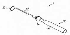
図1は、本発明の一実施形態の電極カテーテル(電極カテーテル1)を模式的に示すが、図示した形態に制限されることはない。電極カテーテル1は、血管を通して体内(例えば、心臓の内部)に挿入され、不整脈の検査や治療等に用いられるものである。この電極 カテーテル1は、長尺状の筒体20(カテーテル本体、カテーテルチューブ、カテーテルシャフト)と、筒体20の近位端にハンドル30を有する。 FIG. 1 schematically shows an electrode catheter (electrode catheter 1) according to an embodiment of the present invention, but is not limited to the illustrated form. The electrode catheter 1 is inserted into the body (for example, inside the heart) through a blood vessel and is used for examination and treatment of arrhythmia. The electrode catheter 1 has a long tubular body 20 (catheter body, catheter tube, catheter shaft) and a
筒体20は、可撓性を有する管状構造(中空のチューブ状部材)からなり、自身の軸方向に沿って、伸びる。具体的には、筒体20の軸方向の長さは、ハンドル30の軸方向の長さと比べて数倍〜数十倍程度、長くてよい。なお、筒体20は、その軸方向に向かって同じ 特性のチューブで構成されていてもよいが、比較的可撓性に優れた先端部分と、この先端部分に対して軸方向に一体に形成されると共に先端部分よりも比較的に剛性のある基端部分とを有してもよい。 The
筒体20は、その軸方向に沿って延在するように内部に1つの内腔(ルーメン、内孔、貫通孔)が形成された、いわゆるシングルルーメン構造、あるいは複数(例えば4つ)の内腔が形成された、いわゆるマルチルーメン構造を有してよい。筒体20は、その内部に操作用ワイヤ(図示せず)を有することができる。 The
筒体20は、その遠位端に先端部22を有する。筒体20は、先端部22を有さなくてもよい。先端部22は、円形状の形態を有するが、直線状であってもよく、適宜その形状を選択することができる。筒体20の遠位端の外側及び/又は先端部22に外部電極(図示せず)を有する。その外部電極に導線(図示せず)が電気的に接続される。 The
ハンドル30は、電極カテーテルを操作するために使用されるハンドルであり、その形状及び大きさ等、特に制限されることはないが、例えば、図1に示すように、その軸方向に沿って伸びる把持部32(ハンドル本体、グリップ)と、この把持部32に対して軸方向にスライド可能に装着された操作部34(ノブ)とを有する。把持部32と操作部34を用いて、電極カテーテル1を操作することができる。把持部32及び操作部34の形状及び大きさ等、適宜選択することができる。 The
以下、本発明を実施例及び比較例により具体的かつ詳細に説明するが、これらの実施例は本発明の一態様にすぎず、本発明はこれらの例によって何ら限定されるものではない。 Hereinafter, the present invention will be described in detail with reference to Examples and Comparative Examples, but these Examples are only one aspect of the present invention, and the present invention is not limited to these Examples.
本実施例で使用した材料を以下に示す。
(A)金属線
(A1)0.069mmの直径を有する炭素鋼でできた金属線(ピアノ線)であって、表面に銅メッキが施されている金属線(株式会社SKKテクノロジー製銅めっきピアノ線)
(A2)0.064mmの直径を有するSUSでできた金属線であって、表面に銅メッキが施されている金属線(株式会社SKKテクノロジー製銅めっきSUS線)
(B)コーティング樹脂層
(B1)フッ素樹脂(AGC株式会社製のルミフロン(登録商標)(商品名)、FEVEに該当する)
(B2)ポリアミドイミド樹脂(日立化成株式会社社製のHPC−1000(商品名))The materials used in this example are shown below.
(A) Metal wire (A1) A metal wire (piano wire) made of carbon steel with a diameter of 0.069 mm and a copper-plated surface (copper-plated piano manufactured by SKK Technology Co., Ltd.). line)
(A2) A metal wire made of SUS having a diameter of 0.064 mm and having a copper-plated surface (copper-plated SUS wire manufactured by SKK Technology Co., Ltd.).
(B) Coating resin layer (B1) Fluororesin (corresponding to Lumiflon (registered trademark) (trade name), FEVE manufactured by AGC Inc.)
(B2) Polyamide-imide resin (HPC-1000 (trade name) manufactured by Hitachi Kasei Co., Ltd.)
実施例1
金属線(A1)の表面にフッ素樹脂(B1)を連続塗装法によりコーティングして、コーティング樹脂層(B1)を有する導線を製造した。得られた導線の外径は0.08mmであった。Example 1
The surface of the metal wire (A1) was coated with a fluororesin (B1) by a continuous coating method to produce a conducting wire having a coated resin layer (B1). The outer diameter of the obtained conductor was 0.08 mm.
実施例2
実施例1において、(B1)の代わりに、ポリアミドイミド樹脂(B2)を使用した他は、実施例1と同様の方法を使用して、コーティング樹脂層(B2)を有する導線を製造した。得られた導線の外径は0.08mmであった。Example 2
In Example 1, a conductor having a coated resin layer (B2) was produced by using the same method as in Example 1 except that the polyamide-imide resin (B2) was used instead of (B1). The outer diameter of the obtained conductor was 0.08 mm.
比較例1
実施例2において、(A1)の代わりに、金属線(A2)を使用した他は、実施例2と同様の方法を使用して、コーティング樹脂層(B2)を有する導線を製造した。得られた導線の外径は0.08mmであった。Comparative Example 1
In Example 2, a conductor having a coated resin layer (B2) was produced by using the same method as in Example 2 except that the metal wire (A2) was used instead of (A1). The outer diameter of the obtained conductor was 0.08 mm.
実施例1〜2及び比較例1の導線を、下記の方法を使用して、評価した。
すべり性(静摩擦係数の測定)
摩擦摩耗試験機 FPR−2100(株式会社レスカ製)を用いてピンオンディスク試験を実施した。PTFEでコーティングした測定ピン(材質:SUJ2、形状:円柱形状、直径3.5mm、長さ250mm)の底面を、コーティング樹脂(B1)又は(B2)をコーティングした板状矩形サンプル(100mm×100mm)に接地後、荷重(100g)条件下、速度(1rpm)、回転半径15mmで当該サンプルを回転して、静摩擦係数を測定した。The conductors of Examples 1 and 2 and Comparative Example 1 were evaluated using the following methods.
Slipability (measurement of coefficient of static friction)
A pin-on disc test was carried out using a friction and wear tester FPR-2100 (manufactured by Reska Co., Ltd.). A plate-shaped rectangular sample (100 mm x 100 mm) in which the bottom surface of a measurement pin (material: SUJ2, shape: cylindrical shape, diameter 3.5 mm, length 250 mm) coated with PTFE is coated with a coating resin (B1) or (B2). After touching the ground, the sample was rotated at a speed (1 rpm) and a turning radius of 15 mm under a load (100 g) condition, and the coefficient of static friction was measured.
座屈強度
縦型電動計測スタンドMX2−500N(株式会社イマダ製)を用いて座屈強度を測定した。測定に用いる金属線又は導線(長さ34mm)の各々の3本を束ねた。各束の両端をカプトンテープ(12mm幅)で固定し、テープで固定されていない金属線又は導線の各束の露出部を10mmとした。測定機のチャックでサンプル両端のテープ固定部(12mm)を保持し、速度10mm/minで圧縮した際の最大荷重を座屈強度とした。Buckling strength The buckling strength was measured using a vertical electric measuring stand MX2-500N (manufactured by Imada Co., Ltd.). Three of each of the metal wire or the conducting wire (
充填可能本数
PTFE製チューブ(長さ450mm、内径0.3mm)を、直線状になるように卓上にテープで固定し、導線(500mm)を、導線の両端部が25mmずつ露出するようにPTFE製チューブに挿入した。挿入した導線は移動しないようにその両端部をテープで固定後、挿入不可になるまで逐次その導線を挿入して、充填できた本数を数えた。
評価結果を、表1に示した。Number of fillable tubes PTFE tubes (length 450 mm, inner diameter 0.3 mm) are fixed on the table with tape so that they are straight, and the conductor (500 mm) is made of PTFE so that both ends of the conductor are exposed by 25 mm. Inserted into a tube. After fixing both ends of the inserted conductor with tape so that it would not move, the conductor was inserted one after another until it became impossible to insert, and the number of filled wires was counted.
The evaluation results are shown in Table 1.

実施例1及び2の導線は、金属線と、金属線の外側を被覆する樹脂コーティングを含み、 前記金属線は、5.0〜15.0N/mm2の座屈強度を有し、前記導線は、PTFEに対して、0.3以下の静摩擦係数を有するので、電極カテーテル用導線として、真直性に優れ、側方での絶縁性に優れ、より細い直径を有することができる。よって、本発明の実施形態の電極カテーテル用導線は、より多数の外部電極を配した電極カテーテルを製造するために好適に使用することができる。The conductors of Examples 1 and 2 include a metal wire and a resin coating that covers the outside of the metal wire, and the metal wirehas a buckling strength of 5.0 to 15.0 N / mm 2 , and the conductor wire. Has a static friction coefficient of 0.3 or less with respect to PTFE, so that it can have excellent straightness, excellent lateral insulation, and a finer diameter as a conducting wire for an electrode catheter. Therefore, the electrode catheter lead wire of the embodiment of the present invention can be suitably used for manufacturing an electrode catheter in which a larger number of external electrodes are arranged.
一方、比較例1の導線は、3.5N/mm2の座屈強度を有する。よって、比較例1の導線は、電極カテーテル用導線として、真直性に劣るので、より多数の外部電極を配した電極カテーテルを製造するために使用することができない。On the other hand, the conductor of Comparative Example 1 has a buckling strength of3.5 N / mm 2. Therefore, the conductor of Comparative Example 1 is inferior in straightness as a conductor for an electrode catheter, and therefore cannot be used for manufacturing an electrode catheter in which a larger number of external electrodes are arranged.
本発明の実施形態の電極カテーテル用導線は、真直性に優れ、側方での絶縁性に優れ、より細い直径を有することができる。よって、本発明の実施形態の電極カテーテル用導線は、より多数の外部電極を配した電極カテーテルを製造するために好適に使用することができる。 The conductor for an electrode catheter according to the embodiment of the present invention has excellent straightness, excellent lateral insulation, and can have a smaller diameter. Therefore, the electrode catheter lead wire of the embodiment of the present invention can be suitably used for manufacturing an electrode catheter in which a larger number of external electrodes are arranged.
1 電極カテーテル、
20 筒体、
22 先端部
30 ハンドル
32 把持部
34 操作部1 electrode catheter,
20 cylinders,
22
Claims (6)
Translated fromJapanese前記導線は、金属線と、金属線の外側を被覆する樹脂コーティングを含み、
前記金属線は、5.0〜15.0N/mm2の座屈強度を有し、
前記導線は、0.3以下の静摩擦係数を有する、電極カテーテル用導線。A conductor for an electrode catheter that is arranged inside the cylinder of an electrode catheter having a cylinder and an external electrode arranged outside the cylinder and is electrically connected to the external electrode.
The conductor includes a metal wire and a resin coating that coats the outside of the metal wire.
The metal wire has a buckling strength of 5.0 to 15.0 N / mm2.
The conductor is a conductor for an electrode catheter having a coefficient of static friction of 0.3 or less.
Priority Applications (1)
| Application Number | Priority Date | Filing Date | Title |
|---|---|---|---|
| JP2019221566AJP7409850B2 (en) | 2019-12-06 | 2019-12-06 | Lead wire for electrode catheter and electrode catheter including the same |
Applications Claiming Priority (1)
| Application Number | Priority Date | Filing Date | Title |
|---|---|---|---|
| JP2019221566AJP7409850B2 (en) | 2019-12-06 | 2019-12-06 | Lead wire for electrode catheter and electrode catheter including the same |
Publications (2)
| Publication Number | Publication Date |
|---|---|
| JP2021090501Atrue JP2021090501A (en) | 2021-06-17 |
| JP7409850B2 JP7409850B2 (en) | 2024-01-09 |
Family
ID=76311057
Family Applications (1)
| Application Number | Title | Priority Date | Filing Date |
|---|---|---|---|
| JP2019221566AActiveJP7409850B2 (en) | 2019-12-06 | 2019-12-06 | Lead wire for electrode catheter and electrode catheter including the same |
Country Status (1)
| Country | Link |
|---|---|
| JP (1) | JP7409850B2 (en) |
Citations (9)
| Publication number | Priority date | Publication date | Assignee | Title |
|---|---|---|---|---|
| JPS5093494U (en)* | 1973-12-25 | 1975-08-06 | ||
| US4810543A (en)* | 1986-10-17 | 1989-03-07 | Tyndale Plains-Hunter Ltd. | Articles having low friction surfaces and production thereof |
| JPH09499A (en)* | 1995-06-22 | 1997-01-07 | Terumo Corp | Guide wire |
| JPH09253063A (en)* | 1996-03-25 | 1997-09-30 | Terumo Corp | Electrode catheter |
| JP2000107296A (en)* | 1998-10-02 | 2000-04-18 | Terumo Corp | Medical wire and its production |
| US20020077687A1 (en)* | 2000-12-14 | 2002-06-20 | Ahn Samuel S. | Catheter assembly for treating ischemic tissue |
| JP2016137020A (en)* | 2015-01-26 | 2016-08-04 | 株式会社カネカ | Electrode catheter and manufacturing method of electrode catheter |
| JP2016137019A (en)* | 2015-01-26 | 2016-08-04 | 株式会社カネカ | Electrode catheter and electrode catheter manufacturing method |
| WO2019156059A1 (en)* | 2018-02-06 | 2019-08-15 | 株式会社カネカ | Catheter and method for producing same |
- 2019
- 2019-12-06JPJP2019221566Apatent/JP7409850B2/enactiveActive
Patent Citations (9)
| Publication number | Priority date | Publication date | Assignee | Title |
|---|---|---|---|---|
| JPS5093494U (en)* | 1973-12-25 | 1975-08-06 | ||
| US4810543A (en)* | 1986-10-17 | 1989-03-07 | Tyndale Plains-Hunter Ltd. | Articles having low friction surfaces and production thereof |
| JPH09499A (en)* | 1995-06-22 | 1997-01-07 | Terumo Corp | Guide wire |
| JPH09253063A (en)* | 1996-03-25 | 1997-09-30 | Terumo Corp | Electrode catheter |
| JP2000107296A (en)* | 1998-10-02 | 2000-04-18 | Terumo Corp | Medical wire and its production |
| US20020077687A1 (en)* | 2000-12-14 | 2002-06-20 | Ahn Samuel S. | Catheter assembly for treating ischemic tissue |
| JP2016137020A (en)* | 2015-01-26 | 2016-08-04 | 株式会社カネカ | Electrode catheter and manufacturing method of electrode catheter |
| JP2016137019A (en)* | 2015-01-26 | 2016-08-04 | 株式会社カネカ | Electrode catheter and electrode catheter manufacturing method |
| WO2019156059A1 (en)* | 2018-02-06 | 2019-08-15 | 株式会社カネカ | Catheter and method for producing same |
Also Published As
| Publication number | Publication date |
|---|---|
| JP7409850B2 (en) | 2024-01-09 |
Similar Documents
| Publication | Publication Date | Title |
|---|---|---|
| JP6821756B2 (en) | Catheter with variable arched distal area | |
| CN111683716B (en) | Catheter and method of manufacturing the same | |
| US20150342672A1 (en) | Double micro-electrode catheter | |
| KR102140881B1 (en) | Defibrillation catheter in deep heart | |
| US20180360333A1 (en) | Electrode catheter | |
| US20080058765A1 (en) | Catheter for linear and circular mapping | |
| JP2012130392A (en) | Electrode catheter | |
| US20220226610A1 (en) | Catheter and method for manufacturing catheter | |
| JP2018164737A (en) | Composite electrode type intracardiac defibrillation catheter and composite electrode type intracardiac defibrillation catheter unit | |
| JP7409850B2 (en) | Lead wire for electrode catheter and electrode catheter including the same | |
| JP3161837U (en) | Medical sheath and medical treatment instrument | |
| CN112244846A (en) | Inflorescence-shaped electrophysiology mapping catheter device | |
| JP5317131B2 (en) | Electrode catheter | |
| JP4925206B2 (en) | Electrode catheter | |
| JP7167307B2 (en) | intracardiac defibrillation catheter | |
| JP2012075800A (en) | Catheter | |
| JP7701213B2 (en) | Electrode Catheter | |
| WO2020261716A1 (en) | Catheter and production method therefor | |
| WO2021186523A1 (en) | Instrument for catheter, catheter body and catheter | |
| WO2020071084A1 (en) | Electrode catheter | |
| JP7187331B2 (en) | Catheter manufacturing method | |
| JP6219805B2 (en) | Electrode catheter | |
| JP6876091B2 (en) | Intracardiac defibrillation catheter | |
| JP7568257B2 (en) | Catheter for measuring cardiac potential | |
| JP2025006086A (en) | Electrode Catheter |
Legal Events
| Date | Code | Title | Description |
|---|---|---|---|
| A621 | Written request for application examination | Free format text:JAPANESE INTERMEDIATE CODE: A621 Effective date:20220819 | |
| A977 | Report on retrieval | Free format text:JAPANESE INTERMEDIATE CODE: A971007 Effective date:20230526 | |
| A131 | Notification of reasons for refusal | Free format text:JAPANESE INTERMEDIATE CODE: A131 Effective date:20230530 | |
| A131 | Notification of reasons for refusal | Free format text:JAPANESE INTERMEDIATE CODE: A131 Effective date:20231017 | |
| RD03 | Notification of appointment of power of attorney | Free format text:JAPANESE INTERMEDIATE CODE: A7423 Effective date:20231122 | |
| A521 | Request for written amendment filed | Free format text:JAPANESE INTERMEDIATE CODE: A523 Effective date:20231214 | |
| TRDD | Decision of grant or rejection written | ||
| A01 | Written decision to grant a patent or to grant a registration (utility model) | Free format text:JAPANESE INTERMEDIATE CODE: A01 Effective date:20231219 | |
| A61 | First payment of annual fees (during grant procedure) | Free format text:JAPANESE INTERMEDIATE CODE: A61 Effective date:20231221 | |
| R150 | Certificate of patent or registration of utility model | Ref document number:7409850 Country of ref document:JP Free format text:JAPANESE INTERMEDIATE CODE: R150 |