JP2021090151A - Storage system and data protection method thereof - Google Patents
Storage system and data protection method thereofDownload PDFInfo
- Publication number
- JP2021090151A JP2021090151AJP2019219834AJP2019219834AJP2021090151AJP 2021090151 AJP2021090151 AJP 2021090151AJP 2019219834 AJP2019219834 AJP 2019219834AJP 2019219834 AJP2019219834 AJP 2019219834AJP 2021090151 AJP2021090151 AJP 2021090151A
- Authority
- JP
- Japan
- Prior art keywords
- authentication code
- encrypted data
- storage
- data
- storage controller
- Prior art date
- Legal status (The legal status is an assumption and is not a legal conclusion. Google has not performed a legal analysis and makes no representation as to the accuracy of the status listed.)
- Pending
Links
Images


Classifications
- H—ELECTRICITY
- H04—ELECTRIC COMMUNICATION TECHNIQUE
- H04L—TRANSMISSION OF DIGITAL INFORMATION, e.g. TELEGRAPHIC COMMUNICATION
- H04L9/00—Cryptographic mechanisms or cryptographic arrangements for secret or secure communications; Network security protocols
- H04L9/32—Cryptographic mechanisms or cryptographic arrangements for secret or secure communications; Network security protocols including means for verifying the identity or authority of a user of the system or for message authentication, e.g. authorization, entity authentication, data integrity or data verification, non-repudiation, key authentication or verification of credentials
- H04L9/3226—Cryptographic mechanisms or cryptographic arrangements for secret or secure communications; Network security protocols including means for verifying the identity or authority of a user of the system or for message authentication, e.g. authorization, entity authentication, data integrity or data verification, non-repudiation, key authentication or verification of credentials using a predetermined code, e.g. password, passphrase or PIN
- H—ELECTRICITY
- H04—ELECTRIC COMMUNICATION TECHNIQUE
- H04L—TRANSMISSION OF DIGITAL INFORMATION, e.g. TELEGRAPHIC COMMUNICATION
- H04L9/00—Cryptographic mechanisms or cryptographic arrangements for secret or secure communications; Network security protocols
- H04L9/08—Key distribution or management, e.g. generation, sharing or updating, of cryptographic keys or passwords
- H04L9/0894—Escrow, recovery or storing of secret information, e.g. secret key escrow or cryptographic key storage
- G—PHYSICS
- G06—COMPUTING OR CALCULATING; COUNTING
- G06F—ELECTRIC DIGITAL DATA PROCESSING
- G06F21/00—Security arrangements for protecting computers, components thereof, programs or data against unauthorised activity
- G06F21/60—Protecting data
- G06F21/602—Providing cryptographic facilities or services
- G—PHYSICS
- G06—COMPUTING OR CALCULATING; COUNTING
- G06F—ELECTRIC DIGITAL DATA PROCESSING
- G06F21/00—Security arrangements for protecting computers, components thereof, programs or data against unauthorised activity
- G06F21/70—Protecting specific internal or peripheral components, in which the protection of a component leads to protection of the entire computer
- G06F21/78—Protecting specific internal or peripheral components, in which the protection of a component leads to protection of the entire computer to assure secure storage of data
- G06F21/79—Protecting specific internal or peripheral components, in which the protection of a component leads to protection of the entire computer to assure secure storage of data in semiconductor storage media, e.g. directly-addressable memories
- G—PHYSICS
- G06—COMPUTING OR CALCULATING; COUNTING
- G06F—ELECTRIC DIGITAL DATA PROCESSING
- G06F21/00—Security arrangements for protecting computers, components thereof, programs or data against unauthorised activity
- G06F21/70—Protecting specific internal or peripheral components, in which the protection of a component leads to protection of the entire computer
- G06F21/78—Protecting specific internal or peripheral components, in which the protection of a component leads to protection of the entire computer to assure secure storage of data
- G06F21/80—Protecting specific internal or peripheral components, in which the protection of a component leads to protection of the entire computer to assure secure storage of data in storage media based on magnetic or optical technology, e.g. disks with sectors
- G—PHYSICS
- G06—COMPUTING OR CALCULATING; COUNTING
- G06F—ELECTRIC DIGITAL DATA PROCESSING
- G06F21/00—Security arrangements for protecting computers, components thereof, programs or data against unauthorised activity
- G06F21/70—Protecting specific internal or peripheral components, in which the protection of a component leads to protection of the entire computer
- G06F21/82—Protecting input, output or interconnection devices
- G06F21/85—Protecting input, output or interconnection devices interconnection devices, e.g. bus-connected or in-line devices
- H—ELECTRICITY
- H04—ELECTRIC COMMUNICATION TECHNIQUE
- H04L—TRANSMISSION OF DIGITAL INFORMATION, e.g. TELEGRAPHIC COMMUNICATION
- H04L9/00—Cryptographic mechanisms or cryptographic arrangements for secret or secure communications; Network security protocols
- H04L9/08—Key distribution or management, e.g. generation, sharing or updating, of cryptographic keys or passwords
- H04L9/0816—Key establishment, i.e. cryptographic processes or cryptographic protocols whereby a shared secret becomes available to two or more parties, for subsequent use
- H04L9/0819—Key transport or distribution, i.e. key establishment techniques where one party creates or otherwise obtains a secret value, and securely transfers it to the other(s)
- H04L9/083—Key transport or distribution, i.e. key establishment techniques where one party creates or otherwise obtains a secret value, and securely transfers it to the other(s) involving central third party, e.g. key distribution center [KDC] or trusted third party [TTP]
- H—ELECTRICITY
- H04—ELECTRIC COMMUNICATION TECHNIQUE
- H04L—TRANSMISSION OF DIGITAL INFORMATION, e.g. TELEGRAPHIC COMMUNICATION
- H04L9/00—Cryptographic mechanisms or cryptographic arrangements for secret or secure communications; Network security protocols
- H04L9/08—Key distribution or management, e.g. generation, sharing or updating, of cryptographic keys or passwords
- H04L9/0861—Generation of secret information including derivation or calculation of cryptographic keys or passwords
- H04L9/0863—Generation of secret information including derivation or calculation of cryptographic keys or passwords involving passwords or one-time passwords
- H—ELECTRICITY
- H04—ELECTRIC COMMUNICATION TECHNIQUE
- H04L—TRANSMISSION OF DIGITAL INFORMATION, e.g. TELEGRAPHIC COMMUNICATION
- H04L9/00—Cryptographic mechanisms or cryptographic arrangements for secret or secure communications; Network security protocols
- H04L9/14—Cryptographic mechanisms or cryptographic arrangements for secret or secure communications; Network security protocols using a plurality of keys or algorithms
- H—ELECTRICITY
- H04—ELECTRIC COMMUNICATION TECHNIQUE
- H04L—TRANSMISSION OF DIGITAL INFORMATION, e.g. TELEGRAPHIC COMMUNICATION
- H04L9/00—Cryptographic mechanisms or cryptographic arrangements for secret or secure communications; Network security protocols
- H04L9/32—Cryptographic mechanisms or cryptographic arrangements for secret or secure communications; Network security protocols including means for verifying the identity or authority of a user of the system or for message authentication, e.g. authorization, entity authentication, data integrity or data verification, non-repudiation, key authentication or verification of credentials
- H04L9/3236—Cryptographic mechanisms or cryptographic arrangements for secret or secure communications; Network security protocols including means for verifying the identity or authority of a user of the system or for message authentication, e.g. authorization, entity authentication, data integrity or data verification, non-repudiation, key authentication or verification of credentials using cryptographic hash functions
- H04L9/3242—Cryptographic mechanisms or cryptographic arrangements for secret or secure communications; Network security protocols including means for verifying the identity or authority of a user of the system or for message authentication, e.g. authorization, entity authentication, data integrity or data verification, non-repudiation, key authentication or verification of credentials using cryptographic hash functions involving keyed hash functions, e.g. message authentication codes [MACs], CBC-MAC or HMAC
Landscapes
- Engineering & Computer Science (AREA)
- Computer Security & Cryptography (AREA)
- Theoretical Computer Science (AREA)
- Signal Processing (AREA)
- Computer Networks & Wireless Communication (AREA)
- Computer Hardware Design (AREA)
- Software Systems (AREA)
- General Physics & Mathematics (AREA)
- General Engineering & Computer Science (AREA)
- Physics & Mathematics (AREA)
- Health & Medical Sciences (AREA)
- Bioethics (AREA)
- General Health & Medical Sciences (AREA)
- Power Engineering (AREA)
- Storage Device Security (AREA)
Abstract
Translated fromJapaneseDescription
Translated fromJapanese本発明は、暗号化データの認証が可能なストレージシステムおよびストレージシステムのデータ保護方法に関する。 The present invention relates to a storage system capable of authenticating encrypted data and a data protection method for the storage system.
フラッシュストレージ用のプロトコルであるNVMe(Non Volatile Memory express)をネットワークに拡張するNVMe over Fabricsが注目されている。 NVMe over Fabrics, which extends NVMe (Non Volatile Memory express), a protocol for flash storage, to networks is drawing attention.
NVMe over Fabricsを用いてストレージコントローラからストレージノードに格納されるデータを保護するためには、ストレージノードに格納されるデータの暗号化(以下、格納データ暗号化と言う)だけでなく、ネットワーク上を通過するデータの暗号化(以下、通信データ暗号化と言う)が必要となる。 In order to protect the data stored in the storage node from the storage controller using NVMe over Fabrics, not only the data stored in the storage node is encrypted (hereinafter referred to as stored data encryption), but also on the network. It is necessary to encrypt the data that passes through (hereinafter referred to as communication data encryption).
このとき、暗号処理をストレージコントローラとストレージノードで分担する方法として、以下の2つの方法がある。 At this time, there are the following two methods as a method of sharing the encryption process between the storage controller and the storage node.
1つ目は、ストレージコントローラで通信データ暗号化にてデータを暗号化し、その暗号化データをネットワークを介してストレージコントローラからストレージノードに送信し、通信データ暗号化にて暗号化されたデータをストレージノードで復号し、その復号化データをストレージコントローラで格納データ暗号化にて暗号化して格納する方法である。 The first is to encrypt the data with communication data encryption with the storage controller, send the encrypted data from the storage controller to the storage node via the network, and store the data encrypted with communication data encryption. This is a method of decrypting with a node and storing the decrypted data with a storage controller by encrypting it with data encryption.
2つ目は、ストレージコントローラで格納データ暗号化にてデータを暗号化し、その暗号化データをストレージコントローラで通信データ暗号化にて暗号化し、格納データ暗号化および通信データ暗号化で2重に暗号化された暗号化データをネットワークを介してストレージコントローラからストレージノードに送信し、2重に暗号化された暗号化データをストレージノードで通信データ復号化することにより、格納データ暗号化にて1重に暗号化されたデータを格納する方法である。 The second is to encrypt the data with the stored data encryption with the storage controller, encrypt the encrypted data with the communication data encryption with the storage controller, and double-encrypt with the stored data encryption and the communication data encryption. The encrypted data is transmitted from the storage controller to the storage node via the network, and the double-encrypted encrypted data is decrypted by the storage node, resulting in a single storage data encryption. It is a method of storing encrypted data in.
また、特許文献1には、暗号化部は、公開鍵により入力されたデータの暗号化を行うとともに、入力したセルのデータからハッシュデータの生成も行い、復号化部は、秘密鍵を用いて暗号化データの復号化を行うとともに、復号化データからハッシュデータを生成し、ハッシュデータが正しいかどうか確認することによりキーデータが正しいキーデータであるかどうかを確認する方法が開示されている。 Further, in
しかしながら、上述した1つ目の暗号化処理は、通信データ復号化および格納データ暗号化をストレージノードで実施する必要があり、ストレージノードの負荷が大きかった。上述した2つ目の暗号化処理は、格納データ暗号化および通信データ暗号化をストレージコントローラで実施する必要があり、ストレージコントローラの負荷が大きかった。 However, in the first encryption process described above, it is necessary to perform communication data decryption and stored data encryption on the storage node, and the load on the storage node is large. In the second encryption process described above, it is necessary to perform the stored data encryption and the communication data encryption on the storage controller, and the load on the storage controller is large.
また、特許文献1には、暗号化に利用したキーデータが正しいものであるかを書き込み側が確認するためにハッシュデータを利用することは開示されているが、書き込まれた側が暗号化データを認証する方法については開示されていない。 Further,
本発明は、上記事情に鑑みなされたものであり、その目的は、暗号処理にかかる負荷を低減しつつ、データの格納および通信の安全性を確保することが可能なストレージシステムおよびストレージシステムのデータ保護方法を提供することにある。 The present invention has been made in view of the above circumstances, and an object of the present invention is a storage system and data of a storage system capable of ensuring data storage and communication security while reducing the load on cryptographic processing. It is to provide a protection method.
上記目的を達成するため、第1の観点に係るストレージシステムは、認証鍵が割り当てられたコントローラとノードを備え、前記コントローラは、暗号鍵を用いてデータを暗号化した暗号化データを生成し、前記認証鍵を用いて前記暗号化データに基づいて認証コードを生成し、前記暗号化データおよび前記認証コードを前記ノードに送信し、前記ノードは、前記コントローラから送信された暗号化データおよび認証コードを受信し、前記暗号化データおよび前記認証コードを保存し、前記保存した暗号化データおよび認証コードを前記コントローラに送信し、前記コントローラは、前記ノードから送信された暗号化データおよび認証コードを受信し、前記ノードから送信された認証コードの検証結果に基づいて、前記暗号化データを復号する。 In order to achieve the above object, the storage system according to the first aspect includes a controller and a node to which an authentication key is assigned, and the controller generates encrypted data obtained by encrypting data using an encryption key. An authentication code is generated based on the encryption data using the authentication key, the encryption data and the authentication code are transmitted to the node, and the node sends the encryption data and the authentication code transmitted from the controller. Is received, the encrypted data and the authentication code are stored, the stored encryption data and the authentication code are transmitted to the controller, and the controller receives the encryption data and the authentication code transmitted from the node. Then, the encrypted data is decrypted based on the verification result of the authentication code transmitted from the node.
本発明によれば、暗号処理にかかる負荷を低減しつつ、データの格納および通信の安全性を確保することができる。 According to the present invention, it is possible to ensure the security of data storage and communication while reducing the load on the encryption process.
実施形態について、図面を参照して説明する。なお、以下に説明する実施形態は特許請求の範囲に係る発明を限定するものではなく、また、実施形態の中で説明されている諸要素およびその組み合わせの全てが発明の解決手段に必須であるとは限らない。 The embodiment will be described with reference to the drawings. It should be noted that the embodiments described below do not limit the invention according to the claims, and all of the elements and combinations thereof described in the embodiments are indispensable for the means for solving the invention. Not necessarily.
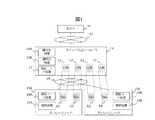
図1は、第1実施形態に係る暗号処理装置が適用されるストレージコントローラおよびストレージノードの構成を示すブロック図である。
図1において、ホスト11は、通信ネットワーク12を介してストレージコントローラ13に接続され、ストレージコントローラ13は、通信ネットワーク14を介してストレージノード15A、15Bに接続されている。ストレージコントローラ13とストレージノード15A、15Bの間では、NVMe over Fabricsに基づいてデータ転送することができる。FIG. 1 is a block diagram showing a configuration of a storage controller and a storage node to which the encryption processing device according to the first embodiment is applied.
In FIG. 1, the
ホスト11は、ストレージノード15A、15Bが提供する容量へのデータの書き込みおよびストレージノード15A、15Bが提供する容量からのデータの読み込みをストレージコントローラ13に指示する。ストレージコントローラ13は、通信ネットワーク12を介して論理ボリュームL1〜L4をホスト11に提供する。ストレージノード15A、15Bは、通信ネットワーク14を介して物理的な容量をストレージコントローラ13に提供する。 The
このとき、ストレージコントローラ13上の論理ボリュームL1〜L4は、ストレージノード15A、15BのボリュームD1〜D4と1対1に対応させることができる。ボリュームD1〜D4は、例えば、ハードディスク装置またはSSD(Solid State Drive)などの物理記憶デバイスである。なお、ストレージノード15A、15Bに示されるボリュームは、論理的なボリュームであってもよいし、物理的なメディア単位であってもよい。 At this time, the logical volumes L1 to L4 on the
そして、ストレージコントローラ13は、論理ボリュームL1〜L4をホスト11に公開し、ホスト11上のOS(Operating System)は、これらの論理ボリュームL1〜L4をマウントし、データのIOを行う。 Then, the
ストレージコントローラ13は、ホスト11から指定された論理ボリュームL1〜L4について、ホスト11からのIOにより入力されるデータをストレージノード15A、15Bとの間で転送し、論理ボリュームL1〜L4に対応するストレージノード15A、15B上のボリュームD1〜D4に書き込みまたは読み込みを行う。 The
ここで、ストレージコントローラ13およびストレージノード15A、15Bを有するストレージシステムは、ストレージコントローラ13とストレージノード15A、15Bとの間で送受信される通信データを保護しつつ、ストレージノード15A、15Bに格納される格納データを保護するため、暗号処理装置を実装する。この暗号処理において、ストレージコントローラ13は、暗号化処理16A、復号化処理16Bおよび認証コード処理17を実行し、各ストレージノード15A、15Bは、認証コード処理18A、18Bおよび保存処理19A、19Bを実行する。 Here, the storage system having the
暗号化処理16Aおよび復号化処理16Bを実行するため、ストレージコントローラ13には、暗号鍵(Data Encryption Key:以下、DEKとも言う)が割り当てられる。認証コード処理17、18A、18Bを実行するため、ストレージコントローラ13および各ストレージノード15A、15Bには、認証鍵(Authentication Key:以下、AKとも言う)が割り当てられる。このとき、認証鍵は、ストレージノード15A、15Bごとに割り当ててもよいし、ボリュームD1〜D4ごとに割り当ててもよい。 In order to execute the
暗号化処理16Aは、暗号鍵を用いてデータを暗号化した暗号化データを生成する。認証コード処理17、18A、18Bは、認証鍵を用いて暗号化データに基づいて認証コードを生成したり、その認証コードを検証したりする。復号化処理16Bは、認証鍵の検証結果に基づいて、暗号化データを復号する。保存処理19A、19Bは、認証鍵の検証結果に基づいて、暗号化データを保存する。 The
書み込み処理では、ストレージコントローラ13は、例えば、論理ボリュームL1に対するデータ書き込み要求をホスト11から受け取ると、そのデータの暗号化処理16Aを実行し、論理ボリュームL1に割り当てられた暗号鍵を用いて暗号化データを生成する。また、ストレージコントローラ13は、認証コード処理17を実行し、ストレージノード15Aに割り当てられた認証鍵を用いて、その暗号化データに基づいて認証コードを作成する。そして、ストレージコントローラ13は、論理ボリュームL1に対応するボリュームD1を図2のマッピングテーブル21から特定し、ボリュームD1に対してそれらの暗号化データと認証コードを通信ネットワーク14を介してストレージノード15Aに送信し、ストレージノード15Aに書き込む。 In the write process, for example, when the
ストレージノード15Aは、暗号化データと認証コードをストレージコントローラ13から受信すると、認証コード処理18Aを実行し、その受信した認証コードを検証する。そして、ストレージノード15Aは、認証コードの検証に成功すると、保存処理19Aを実行し、暗号化データと認証コードをボリュームD1に格納する。 When the
読み込み処理では、ストレージコントローラ13は、例えば、論理ボリュームL1に対するデータ読み込み要求をホスト11から受け取ると、論理ボリュームL1に対応するボリュームD1を図2のマッピングテーブル21から特定し、ボリュームD1に対するデータ読み込み要求をストレージノード15Aに送信する。ストレージコントローラ15Aは、ボリュームD1に対するデータ読み込み要求を受け付けると、該当する暗号化データと認証コードをボリュームD1から取り出し、通信ネットワーク14を介してストレージコントローラ13に送信する。 In the read process, for example, when the
ストレージコントローラ13は、暗号化データと認証コードをストレージノード15Aから受信すると、認証コード処理17を実行し、その受信した認証コードを検証する。そして、ストレージコントローラ13は、認証コードの検証に成功すると、復号化処理16Bを実行し、論理ボリュームL1に割り当てられた暗号鍵を用いて暗号化データを復号し、その復号データをホスト11に応答する。 When the
ここで、ストレージコントローラ13から送信されるデータを暗号化することにより、ストレージノード15A、15Bに保存されたデータの秘匿性を確保することが可能となるとともに、暗号化データとともに送受信される認証コードを検証することにより、TLDなどの通信データ暗号化方式を実施することなく、データ通信時の改ざんおよび成りすましを確認することができる。このため、ストレージコントローラ13とストレージノード15A、15Bとの間で転送されるデータを保護するために、ストレージコントローラ13およびストレージノード15A、15Bにおいて、通信データ暗号化および通信データ復号化を実施する必要がなくなり、ストレージコントローラ13およびストレージノード15A、15Bの暗号処理にかかる負荷を低減することができる。 Here, by encrypting the data transmitted from the
例えば、ストレージコントローラ13は、IEEE p1619で規定されるAES−XTS 256などの格納データ暗号化方式を用いてデータを暗号化した後、暗号化データに対してチェックサムを生成し、このチェックサムから、予めストレージノード15A、15Bと共有している認証鍵を用いて認証コードを生成する。ストレージコントローラ13は、この認証コードを暗号化データとともにストレージノード15A、15Bに送信する。 For example, the
認証コードと暗号化データを受信したストレージノード15A、15Bは、その暗号化データからチェックサムを生成し、予めストレージコントローラ13と共有している認証鍵を用いて認証コードを生成し、ストレージコントローラ13から受信した認証コードと一致するか検証する。ストレージノード15A、15Bは、認証コードの検証に成功すると、送信元の認証と、受信したデータの完全性を確認することができる。データは、通信時に格納データ暗号化方式にて暗号化され、秘匿が守られる。 The
また、ストレージノード15A、15Bは、認証コードの検証に成功した場合のみデータを保存する。このため、データの格納時の秘匿と完全性も保証でき、外部の別のホストまたはストレージコントローラからの不正書き込みを拒否することができる。 Further, the
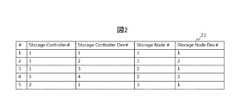
図2は、図1のストレージコントローラで用いられるマッピングテーブルの一例を示す図である。
図2において、マッピングテーブル21は、図1のストレージコントローラ13のボリュームとストレージノード15A、15Bのボリュームとの対応関係を示す。FIG. 2 is a diagram showing an example of a mapping table used in the storage controller of FIG.
In FIG. 2, the mapping table 21 shows the correspondence between the volume of the
マッピングテーブル21は、♯と、Storage Controller#と、Storage Controller Dev#と、Storage Node#と、Storage Node Dev#のエントリを格納する。♯は、エントリ番号を示す。Storage Controller#は、ストレージコントローラの識別情報を示す。Storage Controller Dev#は、ストレージコントローラが提供する論理ボリュームの識別情報を示す。Storage Node#は、ストレージノードの識別情報を示す。Storage Node Dev#は、ストレージノードが提供するボリュームの識別情報を示す。 The mapping table 21 stores the entries of #, the Storage Controller #, the Storage Controller Dev #, the Storage Node #, and the Storage Node Dev #. # Indicates the entry number. Storage Controller # indicates the identification information of the storage controller. Storage Controller Dev # indicates the identification information of the logical volume provided by the storage controller. Storage Node # indicates the identification information of the storage node. Storage Node Dev # indicates the identification information of the volume provided by the storage node.
図2のマッピングテーブル21では、図1のストレージコントローラ13にStorage Controller#=1が付与され、論理ボリュームL1〜L4にStorage Controller Dev#=1〜4がそれぞれ付与され、ストレージノード15A、15BにStorage Node#=1、2がそれぞれ付与され、ストレージノード15AのボリュームD1、D2にStorage Node Dev#=1、2がそれぞれ付与され、ストレージノード15BのボリュームD3、D4にStorage Node Dev#=1、2がそれぞれ付与されている例を示す。 In the mapping table 21 of FIG. 2, Storage Controller # = 1 is assigned to the
このとき、ストレージコントローラ13は、マッピングテーブル21を参照することにより、ストレージコントローラ13の論理ボリュームL1、L2がそれぞれストレージノード15AのボリュームD1、D2にマッピングされ、ストレージコントローラ13の論理ボリュームL3、L4がそれぞれストレージノード15BのボリュームD3、D4にマッピングされていると判断することができる。このため、ストレージコントローラ13は、例えば、ホスト11から読み書き対象として論理ボリュームL1が指定されると、マッピングテーブル21を参照することにより、実際にはストレージコントローラ13のボリュームD1に対してデータを読み書きすることができる。 At this time, the
図3は、図1のストレージコントローラで用いられる暗号鍵管理テーブルの一例を示す図である。
図3において、暗号鍵管理テーブル22は、暗号化データの生成に用いられる暗号鍵を管理する。FIG. 3 is a diagram showing an example of an encryption key management table used in the storage controller of FIG.
In FIG. 3, the encryption key management table 22 manages the encryption key used for generating the encrypted data.
暗号鍵管理テーブル22は、♯と、Storage Controller Dev#と、DEKのエントリを格納する。♯は、エントリ番号を示す。Storage Controller Dev#は、ストレージコントローラが提供する論理ボリュームの識別情報を示す。DEKは、暗号鍵の識別情報を示す。 The encryption key management table 22 stores the entries of #, the Storage Controller Dev #, and the DEK. # Indicates the entry number. Storage Controller Dev # indicates the identification information of the logical volume provided by the storage controller. DEK indicates the identification information of the encryption key.
図3の暗号鍵管理テーブル22では、図1の論理ボリュームL1〜L4にStorage Controller Dev#=1〜4がそれぞれ付与され、論理ボリュームL1〜L4に暗号鍵DEK1〜DEK4がそれぞれ割り当てられている例を示す。 In the encryption key management table 22 of FIG. 3, an example in which Storage Controller Dev # = 1 to 4 are assigned to the logical volumes L1 to L4 of FIG. 1 and encryption keys DEK1 to DEK4 are assigned to the logical volumes L1 to L4, respectively. Is shown.
このとき、ストレージコントローラ13は、暗号鍵管理テーブル22を参照することにより、論理ボリュームL1〜L4ごとに異なる暗号鍵を生成することができる。なお、ストレージコントローラ13は、初期設定時または構成変更等のタイミングで暗号鍵を生成してもよいし、外部の鍵管理サーバ(Key Management Server:以下、KMSとも言う)に暗号鍵を生成させ、鍵管理サーバから暗号鍵を受領してもよい。 At this time, the
図4は、図1のストレージコントローラで用いられる認証鍵対応関係テーブルの一例を示す図である。
図4において、認証鍵対応関係テーブル23は、認証コードの生成に用いられる認証鍵を管理する。図4では、ストレージノード単位に認証鍵を割り当てる例を示した。FIG. 4 is a diagram showing an example of an authentication key correspondence table used in the storage controller of FIG.
In FIG. 4, the authentication key correspondence table 23 manages the authentication key used for generating the authentication code. FIG. 4 shows an example of assigning an authentication key to each storage node.
認証鍵対応関係テーブル23は、♯と、Storage Node#と、Authentication Keyのエントリを格納する。♯は、エントリ番号を示す。Storage Node#は、ストレージノードの識別情報を示す。Authentication Keyは、認証鍵の識別情報を示す。 The authentication key correspondence table 23 stores the entries of #, Storage Node #, and Activation Key. # Indicates the entry number. Storage Node # indicates the identification information of the storage node. The Authentication Key indicates the identification information of the authentication key.
ストレージコントローラが複数から構成され、互いに冗長構成をとる場合は、これらのストレージコントローラ同士で認証鍵を共有する。このとき、認証鍵を共有するストレージコントローラ群が、ストレージノードにデータを書き込むことができる。ストレージノードは、自分が利用する認証鍵を各々管理する。 When the storage controllers are composed of a plurality of storage controllers and have a redundant configuration with each other, the authentication key is shared between these storage controllers. At this time, the storage controller group sharing the authentication key can write data to the storage node. The storage node manages each authentication key used by the storage node.
認証鍵は、手動で管理UI(User Interface)から、ストレージコントローラ13およびストレージノード15A、15Bに設定してもよいし、手動で設定したシークレットキーから派生させてもよいし、Diffie Hellmanのような鍵共有アルゴリズムで共有してもよい。 The authentication key may be manually set in the
また、外部のKMSに認証鍵を作成させ、ストレージコントローラ13およびストレージノード15A、15Bは、KMSから必要な認証鍵を受領してもよい。その際、その対応関係に属するストレージコントローラ13またはストレージノード15A、15Bでなければ対応する認証鍵が入手できないよう、KMIP(Key Management Interoperability Protocol)プロトコルなどの規定に準じてアクセス制御を施す。 Further, the external KMS may be made to create an authentication key, and the
例えば、ストレージコントローラ13は、KMSに必要数の認証鍵の作成を指示し、KMSから認証鍵とともに認証鍵のUUIDを取得するとともに、ストレージコントローラ13とストレージノード15A、15B間でTLSなどで保護された管理インタフェイスを経由し、該当する認証鍵のUUIDをストレージノード15A、15Bに提供する。そして、ストレージノード15A、15Bは、TLS(Transport Layer Security)などで保護されたKMSとの間の通信を通じて、UUID(Universally Unique Identifier)を指定して認証鍵を取得する。これにより、ストレージコントローラ13とストレージノード15A、15Bで認証鍵を共有することができる。 For example, the
ストレージコントローラ13は、認証鍵対応関係テーブル23を参照することにより、ストレージノード15Aの論理ボリュームL1、L2に書き込まれたデータの認証鍵がAK1あることを判定し、AK1で認証コードを作成し、ストレージノード15AのボリュームD1、D2に書き込みを実施し、ストレージノード15Aは、予め保持するAK1を用いて認証コードを検証し、認証コードの検証に成功したら、論理ボリュームL1、L2に書き込まれたデータをボリュームD1、D2にそれぞれ保存することができる。 The
なお、認証鍵を割り当てる単位は、図4に示すように、必ずしもストレージノード15A、15B単位である必要はなく、様々な単位で設定できる。例えば、ストレージノード15A、15Bのデバイス単位に設定することもできる。 As shown in FIG. 4, the unit for assigning the authentication key does not necessarily have to be the
図5は、図1のストレージコントローラで用いられる認証鍵対応関係テーブルのその他の例を示す図である。図5では、ストレージノードのデバイス単位に認証鍵を割り当てる例を示した。
図5において、認証鍵対応関係テーブル24は、♯と、Storage Node#と、Storage Node Dev#と、Authentication Keyのエントリを格納する。♯は、エントリ番号を示す。Storage Node#は、ストレージノードの識別情報を示す。Storage Node Dev#は、ストレージノードが提供するボリュームの識別情報を示す。Authentication Keyは、認証鍵の識別情報を示す。FIG. 5 is a diagram showing another example of the authentication key correspondence table used in the storage controller of FIG. FIG. 5 shows an example of assigning an authentication key to each device of the storage node.
In FIG. 5, the authentication key correspondence table 24 stores the entries of #, Storage Node #, Storage Node Dev #, and Activation Key. # Indicates the entry number. Storage Node # indicates the identification information of the storage node. Storage Node Dev # indicates the identification information of the volume provided by the storage node. The Authentication Key indicates the identification information of the authentication key.
ストレージコントローラ13は、認証鍵対応関係テーブル24を参照することにより、ストレージノード15Aの論理ボリュームL1に書き込まれたデータの認証鍵がAK1あることを判定し、AK1で認証コードを作成し、ストレージノード15AのボリュームD1に書き込みを実施し、ストレージノード15Aは、予め保持し、ボリュームD1に割り当てられているAK1を用いて認証コードを検証し、認証コードの検証に成功したら、論理ボリュームL1に書き込まれたデータをボリュームD1に保存することができる。 The
図6は、図1のストレージコントローラで用いられる認証コードテーブルの一例を示す図である。
図6において、認証コードテーブル25は、各データに関する最新の認証コードを管理する。FIG. 6 is a diagram showing an example of an authentication code table used in the storage controller of FIG.
In FIG. 6, the authentication code table 25 manages the latest authentication code for each data.
認証コードテーブル25は、♯と、Storage Controller Dev#と、Storage Node#と、Storage Node Dev#と、認証コードLBA1〜LBA4・・のエントリを格納する。♯は、エントリ番号を示す。Storage Controller Dev#は、ストレージコントローラが提供する論理ボリュームの識別情報を示す。Storage Node#は、ストレージノードの識別情報を示す。Storage Node Dev#は、ストレージノードが提供するボリュームの識別情報を示す。認証コードLBA1〜LBA4・・は、各データに関する最新の認証コードのLBA(Logical Block Addressing)を示す。 The authentication code table 25 stores the entries of #, the Storage Controller Dev #, the Storage Node #, the Storage Node Dev #, and the authentication codes LBA1 to LBA4. # Indicates the entry number. Storage Controller Dev # indicates the identification information of the logical volume provided by the storage controller. Storage Node # indicates the identification information of the storage node. Storage Node Dev # indicates the identification information of the volume provided by the storage node. The authentication codes LBA1 to LBA4 ... Indicates the latest authentication code LBA (Logical Block Addressing) for each data.
ストレージコントローラ13は、認証コードテーブル25を保持することで、ストレージノード15A、15Bから読み出したデータが最新であることを確認することができ、ストレージコントローラ13でデータ読み出し時に認証コードを作り直さなくても、ここの認証コードに登録される認証コードと比較することにより、繰り返し攻撃からデータを保護することができる。なお、複数のストレージコントローラが冗長構成をとる場合は、認証コードテーブル25の情報もストレージコントローラ間で共有される。 By holding the authentication code table 25, the
図7は、図1のストレージコントローラの書き込み処理を示すフローチャートである。
図7において、ストレージコントローラ13は、ホスト11からデータの書き込みを受け付けると(C11)、ストレージコントローラ13に割り当てられた暗号鍵を用いてデータを暗号化する(C12)。FIG. 7 is a flowchart showing a write process of the storage controller of FIG.
In FIG. 7, when the
次に、ストレージコントローラ13と各ストレージノード15A、15Bとで共有する認証鍵を用いて認証コードを作成し(C13)、これらの暗号化データと認証コードをストレージノード15A、15Bに書き込む(C14)。データ暗号化は、例えば、IEEE p1619で規定されるAES−XTS 256などの方式により実施する。認証コードには、暗号化データの書き込み元が、このストレージコントローラ13であることが検証できる情報が含まれる。 Next, an authentication code is created using the authentication key shared by the
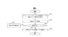
図8は、図1のストレージノードの書き込み処理を示すフローチャートである。
図8において、各ストレージノード15A、15Bは、暗号化データと認証コードの書き込みをストレージコントローラ13から受け付けると(N11)、認証コードの検証を行う(N12)。FIG. 8 is a flowchart showing a write process of the storage node of FIG.
In FIG. 8, when the
この認証コードの検証では、各ストレージノード15A、15Bは、ストレージコントローラ13と共有する認証鍵を用いて、ストレージコントローラ13から受信した暗号化データに基づいて認証コードを生成する。そして、各ストレージノード15A、15Bは、ストレージコントローラ13から受信した認証コードと、各ストレージノード15A、15Bで生成した認証コードが一致するかどうか確認する。 In the verification of the authentication code, each of the
各ストレージノード15A、15Bは、認証コードの検証の結果、認証コードに含まれる情報から適切な書き込み元であることが検証できない場合は検証に失敗し(N13のNo)、書き込み処理に失敗し(N14)、その暗号化データは保存しない。各ストレージノード15A、15Bは、認証コードの検証の結果、正しい書き込み元であることの検証に成功したら(N13のYes)、暗号化データと認証コードを保存する(N15)。 As a result of the verification of the authentication code, each
図9は、図1のストレージコントローラの読み込み処理を示すフローチャートである。
図9において、ストレージコントローラ13は、ホスト11からの読み込み要求を受け付けると(C21)、ストレージノード15A、15Bから暗号化データと認証コードを読み込み(C22)、認証コードを検証する(C23)。FIG. 9 is a flowchart showing a reading process of the storage controller of FIG.
In FIG. 9, when the
この認証コードの検証では、ストレージコントローラ13は、ストレージノード15A、15Bと共有する認証鍵を用いて、ストレージノード15A、15Bから受信した暗号化データに基づいて認証コードを生成する。そして、ストレージコントローラ13は、ストレージノード15A、15Bから受信した認証コードと、ストレージコントローラ13で生成した認証コードが一致するかどうか確認する。 In this verification of the authentication code, the
ストレージコントローラ13は、認証コードの検証に失敗した場合は(C24のNo)、読み込み処理は失敗する(C25)。ストレージコントローラ13は、認証コードの検証に成功すると(C24のYes)、ストレージノード15A、15Bから受信した暗号化データを復号化し(C26)、ホスト11に応答する(C27)。 If the
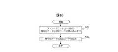
図10は、図1のストレージノードの読み込み処理を示すフローチャートである。
図10において、各ストレージノード15A、15Bは、暗号化データと認証コードの読み込みをストレージコントローラ13から要求されると(N21)、暗号化データと認証コードをストレージコントローラ13に応答する(N22)。FIG. 10 is a flowchart showing a reading process of the storage node of FIG.
In FIG. 10, each
ここで、データを暗号化することにより、ストレージコントローラ13とストレージノード15A、15Bとの間のデータ通信時にデータを保護することができる。また、ストレージノードド15A、15B内に格納されているデータは暗号化されているため、不正な読み出しによる漏洩も防ぐことができる。 Here, by encrypting the data, it is possible to protect the data during data communication between the
認証コードを付与することにより、正しいストレージコントローラ13以外からのストレージノード15A、15Bへの書き込みを防ぐことができる。そのため、ストレージノード15A、15B内に格納されるデータの不正な破壊も防ぐことができる。さらに、ストレージコントローラ13がストレージノード15A、15Bから読み込むデータが改ざんされたデータではないことを確認することができる。 By assigning the authentication code, it is possible to prevent writing to the
この結果、ストレージコントローラ13とストレージノード15A、15Bとの間のデータ通信において、FC−SP2およびTLSなどで代表される通信データ暗号化によりデータを暗号化することなく、送信元の成りすましおよびデータの改ざんからデータを保護することができ、暗号処理にかかる負荷を軽減することができる。 As a result, in the data communication between the
図11は、図1のストレージコントローラとストレージノードとの間でやりとりされる情報の一例を示す図である。
図11において、ストレージコントローラ13と各ストレージノード15A、15Bとの間では、例えば、512バイト単位の暗号化データと、2バイトの認証コードと、6バイトのシーケンス番号とを同時に送受信することができる。シーケンス番号は、暗号化データの送信の通し番号である。FIG. 11 is a diagram showing an example of information exchanged between the storage controller of FIG. 1 and the storage node.
In FIG. 11, between the
このとき、各ストレージノード15A、15B内のデバイスには、これらのデータを連結した状態で保存してもよいし、認証コードとシーケンス番号をLBAに対応付けて、別領域に保存するようにしてもよい。 At this time, these data may be stored in the devices in the
それぞれのデバイスに、暗号化データ、認証コードおよびシーケンス番号を連結するなどして格納する場合、各データをそれぞれのデバイスに格納するようにしてもよい。暗号化データを保存する専用デバイスと、認証コードおよびシーケンス番号などのメタ情報を格納するデバイスに分けて格納するようにしてもよい。 When the encrypted data, the authentication code, and the sequence number are concatenated and stored in each device, each data may be stored in each device. It may be divided into a dedicated device for storing encrypted data and a device for storing meta information such as an authentication code and a sequence number.
図12は、第2実施形態に係るストレージコントローラの書き込み処理を示すフローチャートである。図12では、図7の処理の詳細処理の一例を示す。
図12において、ストレージコントローラ13は、ホスト11からデータの書き込みを受け付けると(C31)、どのストレージノードのどのアドレスに書き込みするかを書き込みアドレスから判定する(C32)。ストレージコントローラ13は、図2のマッピング情報に基づいて、この判定処理を行うことができる。FIG. 12 is a flowchart showing a write process of the storage controller according to the second embodiment. FIG. 12 shows an example of detailed processing of the processing of FIG. 7.
In FIG. 12, when the
例えば、図1の構成では、ストレージコントローラ13がホスト11に開示している論理デバイス1つと、この論理デバイスに書き込まれたデータを書き込むストレージノード15A、15B上のデバイス1つが1対1で対応付けられている。このため、ストレージコントローラ13は、図2のマッピングテーブル21を参照することにより、書き込むストレージノード15A、15Bとデバイスを判定することができる。ストレージコントローラ13は、ホスト11から書き込みを指示されたLBAを用い、そのストレージノード15A、15BのデバイスのLBAに書き込みを行う。 For example, in the configuration of FIG. 1, one logical device disclosed by the
次に、ストレージコントローラ13は、書き込み要求されたデータを処理するDEKとAKを取得する(C33)。ストレージコントローラ13は、図3または図4の情報を管理することでDEKとAKを取得可能である。 Next, the
次に、ストレージコントローラ13は、DEKを用いてデータを暗号化する(C34)。ここでは、AES−XTSを利用してデータを暗号化する例を示している。AES−XTSでは、LBAを入力値として使うため、同じデータであってもアドレスが異なれば、異なる暗号化データが生成される。 Next, the
次に、ストレージコントローラ13は、シーケンス番号を1だけ繰り上げる(C35)。シーケンス番号は、繰り返し攻撃を防ぐために用いられる。シーケンス番号は、ストレージコントローラ単位でインクリメントする方法、ストレージコントローラの論理デバイスとストレージノードのデバイスの対の単位でインクリメントする方法など、いくつかの単位で設定する方法があるが、ここでは特記しない場合、ストレージコントローラの論理デバイスとストレージノードのデバイスの対の単位でインクリメントする方法を想定する。 Next, the
なお、シーケンス番号の代わりに乱数を毎回生成してもよいし、長期に渡る一意性を保証するために、時刻などの情報とシーケンス番号の組み合わせをシーケンス番号の代わりに利用してもよい。 A random number may be generated every time instead of the sequence number, or a combination of information such as time and the sequence number may be used instead of the sequence number in order to guarantee uniqueness over a long period of time.
次に、暗号化データとシーケンス番号を連結したデータを作成し、AKを鍵とし、その連結したデータをメッセージとしてHMAC(Hash based Message Authentication Code)処理を行う(C36)。このとき、このメッセージの先頭2バイトを認証コードとして利用することができる。 Next, data in which encrypted data and sequence numbers are concatenated is created, AK is used as a key, and HMAC (Hash based Message Authentication Code) processing is performed using the concatenated data as a message (C36). At this time, the first 2 bytes of this message can be used as the authentication code.
次に、ストレージコントローラ13は、この認証コードをLBAと対応付けてストレージコントローラ13内に保存する(C37)。このとき、該当するLBAの最新の認証コードが図6の認証コードテーブル25に上書きされる。 Next, the
次に、ストレージコントローラ13は、認証コードおよび平文のシーケンス番号とともに、暗号化データをストレージノード15A、15Bに書き込む(C38)。 Next, the
図13は、第2実施形態に係るストレージコントローラの読み込み処理を示すフローチャートである。図13では、図9の処理の詳細処理の一例を示す。
図13において、ストレージコントローラ13は、ホスト11からLBAとともにデータ読み込み要求を受け付けると(C41)、該当するストレージノード15A、15BのLBAから、暗号化データと、その暗号化データに関連付けられた認証コードおよびシーケンス番号を読み込み(C42)、該当するデータを処理するDEKおよびAKを取得する(C43)。FIG. 13 is a flowchart showing a reading process of the storage controller according to the second embodiment. FIG. 13 shows an example of detailed processing of the processing of FIG.
In FIG. 13, when the
次に、ストレージコントローラ13は、図9のC23の認証コードの検証として、2つの検証を行う。1つ目は、ストレージコントローラ13は、ストレージノード15A、15Bから読み込んだ認証コードが、図6の該当するLBAに保持している認証コードと一致しているかを確認する(C44)。これにより、過去に正しくストレージコントローラ13がストレージノード15A、15Bに書き込んだデータであっても、最新でないデータの読み込みを防止することができる。 Next, the
ストレージコントローラ13は、認証コードが一致しない場合は(C45のNo)、本データの読み込み処理を失敗で終了する(C46)。ストレージコントローラ13は、認証コードが一致すれば(C45のYes)、2つ目の検証として、図12の処理で認証コードを生成したのと同じ方法で認証コードを生成し、ストレージノード15A、15Bから取得した認証コードと比較する(C47)。ストレージコントローラ13は、これらの認証コードが一致しない場合は(C48のNo)、本データの読み込み処理を失敗で終了する(C46)。ストレージコントローラ13は、これらの認証コードが一致すれば(C48のYes)、ストレージノード15A、15Bから受信した暗号化データを復号化し(C49)、ホスト11に応答する(C50)。 If the authentication codes do not match (No in C45), the
図14は、第2実施形態に係るストレージノードの書き込み処理を示すフローチャートである。図14では、図8の処理の詳細処理の一例を示す。
図14において、ストレージノード15A、15Bは、認証コードおよび平文のシーケンス番号とともに、暗号化データをストレージコントローラ13から受信すると(N31)、シーケンス番号が過去に利用されたものでないか確認する(N32)。ストレージノード15A、15Bは、シーケンス番号が過去に利用済みかどうかを判定するために、過去に受信したシーケンス番号を記憶する。シーケンス番号が過去に利用済みの番号であれば(N33のYes)、ストレージノード15A、15Bは、本データの書き込み処理を失敗で終了する(N38)。FIG. 14 is a flowchart showing a writing process of the storage node according to the second embodiment. FIG. 14 shows an example of detailed processing of the processing of FIG.
In FIG. 14, when the
一方、シーケンス番号が過去に利用済みではない場合(N33のNo)、ストレージノード15A、15Bは、図5の認証鍵対応関係テーブル24を参照し、N31で受信したデータを処理するAKを取得する(N34)。 On the other hand, when the sequence number has not been used in the past (No in N33), the
次に、ストレージノード15A、15Bは、暗号化データとシーケンス番号から、図12のC36の処理と同じ方式によりデータを連結し、AKを鍵としてHMAC処理を行う(N35)。そして、ストレージノード15A、15Bは、HMAC処理で生成した先頭2バイトの情報を、ストレージコントローラ13から受信した認証コードと比較する(N36)。ストレージノード15A、15Bは、これらの認証コードが一致しない場合(N37のNo)、本データの書き込み処理を失敗で終了する(N38)。ストレージノード15A、15Bは、これらの認証コードが一致すれば(N37のYes)、暗号化データを指定アドレスに保存し、認証コードとシーケンス番号を予め規定されたアドレスに保存する(N39)。 Next, the
図15は、シーケンス番号が過去に利用されたものでないかの確認方法を示す図である。
図15において、ストレージノード15A、15Bは、シーケンス番号が過去に利用済みかどうかを判定するため、受領済シーケンス番号リスト131〜133を管理する。FIG. 15 is a diagram showing a method of confirming whether or not the sequence number has been used in the past.
In FIG. 15, the
受領済シーケンス番号リスト131は、受領したデータに含まれるシーケンス番号が、未受領と判断された場合に、昇順に追加されていく状態を示す。この例では、直近のシーケンス番号101〜103を登録したところを示す。各受領済シーケンス番号リスト131〜133の最後には、NULLが記載される。このNULLは、各受領済シーケンス番号リスト131〜133の最後の判定に用いられる。 The received
このとき、これら3つのシーケンス番号101〜103は連続するため、過去に利用されたものであるかどうかを示すために、シーケンス番号103のみを残し、シーケンス番号101、102は削除してよい。ストレージノード15A、15Bは、シーケンス番号103の情報から、シーケンス番号103以下のシーケンス番号は受領済と確認することができる。 At this time, since these three
通信が欠落せず、送信側が発行した順番通りに受信側が受信する場合は、ストレージノード15A、15Bは、最後のシーケンス番号を保持するだけで、過去に利用されたシーケンス番号であるか判断可能である。 If communication is not lost and the receiving side receives in the order issued by the transmitting side, the
受領シーケンス番号リスト132は、100番までのシーケンス番号を受領した後、シーケンス番号101〜103、105、110を受領した状態を示す。この際、シーケンス番号101〜103は連番のため、シーケンス番号101、102は受領シーケンス番号リスト132から削除することができ、シーケンス番号103、105、110のみを受領シーケンス番号リスト133に保持すればよい。新たに受領したシーケンス番号は、先頭の103以下であるか、それ以外のシーケンス番号(ここでは105、110)に一致している場合、受領済と判断され、そうでないものは未受領と判断される。 The receipt
処理を一定時間継続すると、受領シーケンス番号が桁溢れし、0からシーケンス番号を振りなおす必要がある場合がある。このようなケースで過去のシーケンス番号が不正に利用されないよう、十分長い桁を使うなどを工夫するのは一般的なシーケンス番号の利用と同様である。また、一定時間継続すると、受領シーケンス番号を格納するメモリに収まらなくなる可能性がある。この場合、受領シーケンス番号を一部破棄し、破棄した最大のシーケンス番号以下のシーケンス番号を受領済と判定し、受け付けないなどの処理が必要となる。 If the processing is continued for a certain period of time, the received sequence number overflows, and it may be necessary to reassign the sequence number from 0. In such a case, it is the same as the use of a general sequence number to devise such as using a sufficiently long digit so that the past sequence number is not used illegally. Also, if it continues for a certain period of time, it may not fit in the memory that stores the receipt sequence number. In this case, it is necessary to partially discard the received sequence number, determine that the sequence number equal to or less than the discarded maximum sequence number has been received, and reject the received sequence number.
なお、ストレージノード15A、15Bは、ストレージコントローラ13から受信した暗号化データを書き込む際、暗号化データと、認証コードと、シーケンス番号を別メッセージで書き込んでもよい。例えば、ストレージノード15A、15Bは、認証コードとシーケンス番号が512バイトの倍数になるまで書き込みを待ち、512バイトの倍数になったらまとめて書き込むようにしてもよい。 When writing the encrypted data received from the
その場合、ストレージノード15A、15Bが書き込みデータを検証して書き込むのは、該当する暗号化データの認証コードとシーケンス番号を受信した以降になる。このとき、ストレージノード15A、15Bは、あらかじめ定められた一定時間、認証コードとシーケンス番号を受信できない場合に、ストレージノード15A、15Bがこれ以上処理を継続しないことを示す信号をストレージコントローラ13に応答し、ストレージコントローラ13がこの信号を受信すると、それ以上書き込みを継続しないことで、データが損失することを防ぐことができる。 In that case, the
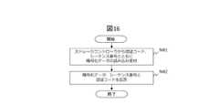
図16は、第2実施形態に係るストレージノードの読み込み処理を示すフローチャートである。図16では、図10の処理の詳細処理の一例を示す。
図16において、ストレージノード15A、15Bは、ストレージコントローラ13から認証コードおよびシーケンス番号とともに、暗号化データの読み込みの要求を受け付けると(N41)、認証コード、シーケンス番号および暗号化データをストレージコントローラ13に応答する(N42)。FIG. 16 is a flowchart showing a storage node reading process according to the second embodiment. FIG. 16 shows an example of detailed processing of the processing of FIG.
In FIG. 16, when the
なお、図16の例では、ストレージコントローラ13から認証コードおよびシーケンス番号とともに、暗号化データの読み込みの要求を受け付ける例を示したが、ストレージノード15A、15Bは、暗号化データと、この暗号化データに対応する認証コードおよびシーケンス番号を対応付けて管理し、ストレージコントローラ13が暗号化データの読み込みのみを要求した際に、認証コードおよびシーケンス番号を暗号化データとともにストレージコントローラ13に応答するようにしてもよい。 In the example of FIG. 16, an example of receiving a request for reading encrypted data together with an authentication code and a sequence number from the
図13のストレージコントローラの読み込み処理では、図9のC23の認証コードの検証として、2つの検証を行う方法について説明した。しかし、図12のストレージコントローラの書き込み処理で、ストレージノード15A、15B上のデータを不正に破壊および改ざんすることを防ぐことができているという前提があり、データ読み取りの際は、上位アプリケーションがデータの破壊・改ざんを検出することができ、再読み込みなどができる場合がある。このような場合には、図13の2つの検証の一部またはすべてを省略するようにしてもよい。 In the reading process of the storage controller of FIG. 13, a method of performing two verifications as verification of the authentication code of C23 of FIG. 9 has been described. However, it is premised that the data on the
図17は、第3実施形態に係るストレージコントローラの読み込み処理を示すフローチャートである。なお、図17では、図13の2つの検証の両方を省略した例を示す。
図17において、ストレージコントローラ13は、ホスト11からの読み込み要求を受け付けると(C61)、ストレージノード15A、15Bから暗号化データを読み込む(C62)。FIG. 17 is a flowchart showing a reading process of the storage controller according to the third embodiment. Note that FIG. 17 shows an example in which both of the two verifications of FIG. 13 are omitted.
In FIG. 17, when the
次に、ストレージコントローラ13は、ストレージノード15A、15Bから受信した暗号化データを処理するDEKを取得し(C63)、そのDEKを用いて暗号化データを復号化し(C64)、ホスト11に応答する(C65)。 Next, the
図18は、第4実施形態に係るストレージコントローラの読み込み処理を示すフローチャートである。なお、図18では、図13の2つの検証のうち2つ目を省略した例を示す。
図18において、ストレージコントローラ13は、ホスト11からデータ読み込み要求を受け付けると(C71)、ストレージノード15A、15Bから、暗号化データと、その暗号化データに関連付けられた認証コードを読み込み(C72)、該当するデータを処理するDEKを取得する(C73)。FIG. 18 is a flowchart showing a reading process of the storage controller according to the fourth embodiment. Note that FIG. 18 shows an example in which the second of the two verifications in FIG. 13 is omitted.
In FIG. 18, when the
次に、ストレージコントローラ13は、ストレージノード15A、15Bから読み込んだ認証コードが、ストレージコントローラ13が保持している認証コードと一致しているかを確認する(C74)。 Next, the
ストレージコントローラ13は、これらの認証コードが一致しない場合は(C75のNo)、本データの読み込み処理を失敗で終了する(C76)。ストレージコントローラ13は、認証コードが一致すれば(C75のYes)、ストレージノード15A、15Bから受信した暗号化データを復号化し(C77)、ホスト11に応答する(C78)。 If these authentication codes do not match (No in C75), the
図19は、第5実施形態に係るストレージコントローラの読み込み処理を示すフローチャートである。なお、図19では、図13の2つの検証のうち1つ目を省略した例を示す。
図19において、ストレージコントローラ13は、ホスト11からデータ読み込み要求を受け付けると(C81)、ストレージノード15A、15Bから、暗号化データと、その暗号化データに関連付けられた認証コードおよびシーケンス番号を読み込み(C82)、該当するデータを処理するDEKおよびAKを取得する(C83)。FIG. 19 is a flowchart showing a reading process of the storage controller according to the fifth embodiment. Note that FIG. 19 shows an example in which the first of the two verifications in FIG. 13 is omitted.
In FIG. 19, when the
次に、ストレージコントローラ13は、図12の処理で認証コードを生成したのと同じ方法で認証コードを生成し、ストレージノード15A、15Bから取得した認証コードと比較する(C84)。ストレージコントローラ13は、これらの認証コードが一致しない場合は(C85のNo)、本データの読み込み処理を失敗で終了する(C86)。ストレージコントローラ13は、これらの認証コードが一致すれば(C85のYes)、ストレージノード15A、15Bから受信した暗号化データを復号化し(C87)、ホスト11に応答する(C88)。 Next, the
図13の読み込み処理では、ストレージコントローラ13は、認証コードをストレージコントローラ13内に保持し、読み込み時に認証コードを比較することで最新のデータであることを検証し、過去のデータを用いた繰り返し攻撃を防いでいる。 In the reading process of FIG. 13, the
過去のデータを用いた繰り返し攻撃を防ぐために、ストレージノード15A、15Bは、ストレージノード15A、15Bで生成したシーケンス番号を用いて、図12の方法と同様の方式で新しい認証コードを生成し、この新しい認証コードをストレージコントローラ13が検証するようにしてもよい。 In order to prevent repeated attacks using the past data, the
図20は、第6実施形態に係るストレージノードの読み込み処理を示すフローチャートである。なお、図12では、ストレージコントローラがシーケンス番号を管理する方法を示したが、図20では、ストレージノードがシーケンス番号を管理する方法を示す。
図20において、ストレージノード15A、15Bは、ストレージコントローラ13から、認証コードおよびシーケンス番号とともに、暗号化データの読み込みを受け付ける(N51)。次に、ストレージノード15A、15Bは、シーケンス番号を1だけ繰り上げる(N52)。FIG. 20 is a flowchart showing a storage node reading process according to the sixth embodiment. Note that FIG. 12 shows a method in which the storage controller manages the sequence number, but FIG. 20 shows a method in which the storage node manages the sequence number.
In FIG. 20, the
次に、ストレージノード15A、15Bは、AKを鍵とし、暗号化データとシーケンス番号を連結したデータをメッセージとしてHMAC処理を行う(N53)。次に、ストレージノード15A、15Bは、このメッセージの先頭2バイトを認証コードとして利用し、この認証コードを書き込みアドレスと対応付けてストレージノード15A、15B内に保存する(N54)。 Next, the
次に、ストレージノード15A、15Bは、認証コードおよびシーケンス番号とともに、暗号化データをストレージコントローラ13に応答する(N55)。 Next, the
図21は、第6実施形態に係るストレージコントローラの読み込み処理を示すフローチャートである。なお、図13では、ストレージコントローラがシーケンス番号を管理する方法を示したが、図21では、ストレージノードがシーケンス番号を管理する方法を示す。
図21において、ストレージコントローラ13は、ホスト11からデータ読み込み要求を受け付けると(C91)、ストレージノード15A、15Bから、認証コードおよびシーケンス番号とともに、暗号化データを読み込む(C92)。FIG. 21 is a flowchart showing a reading process of the storage controller according to the sixth embodiment. Although FIG. 13 shows a method in which the storage controller manages the sequence number, FIG. 21 shows a method in which the storage node manages the sequence number.
In FIG. 21, when the
次に、ストレージコントローラ13は、ストレージノード15A、15Bから読み込んだシーケンス番号が、過去に利用されたシーケンス番号と一致しているかを確認する(C93)。ストレージコントローラ13は、シーケンス番号が過去に利用済みかどうかを判定するために、過去に受信したシーケンス番号を記憶する。 Next, the
ストレージコントローラ13は、ストレージノード15A、15Bから読み込んだシーケンス番号が利用済みの場合は(C94のYes)、本データの読み込み処理を失敗で終了する(C98)。ストレージコントローラ13は、ストレージノード15A、15Bから読み込んだシーケンス番号が利用済みでない場合は(C94のNo)、、該当するデータを処理するDEKおよびAKを取得する(C95)。 If the sequence numbers read from the
次に、ストレージコントローラ13は、暗号化データとシーケンス番号から、図12のC36の処理と同じ方式によりデータを連結し、AKを鍵としてHMAC処理を行う。そして、ストレージコントローラ13は、HMAC処理で生成した先頭2バイトの情報を、ストレージノード15A、15Bから受信した認証コードと比較する(N96)。 Next, the
ストレージコントローラ13は、これらの認証コードが一致しない場合は(C97のNo)、本データの読み込み処理を失敗で終了する(C98)。ストレージコントローラ13は、これらの認証コードが一致すれば(C97のYes)、ストレージノード15A、15Bから受信した暗号化データを復号化し(C99)、ホスト11に応答する(C100)。 If these authentication codes do not match (No in C97), the
図22は、第7実施形態に係る暗号処理装置が適用されるストレージコントローラおよびストレージノードの構成を示すブロック図である。
図22において、このストレージシステムでは、図1のストレージコントローラ13の代わりにストレージコントローラ33が設けられている。FIG. 22 is a block diagram showing a configuration of a storage controller and a storage node to which the encryption processing device according to the seventh embodiment is applied.
In FIG. 22, in this storage system, a
ストレージコントローラ33は、論理ボリュームL1〜L3をプールP1を介して管理し、そのプールP1のデータ領域の単位が、1つ以上のストレージノード15A、15Bの複数のボリュームD1〜D4に分散配置されている。このとき、ストレージコントローラ33は、ボリュームD1〜D4に対してプールボリュームV1〜V4をそれぞれ生成し、プールボリュームV1〜V4をプールP1に一元化する。そして、ストレージコントローラ33は、プールP1から論理ボリュームL1〜L4を切り出し、ホスト11に提供する。 The
ストレージコントローラ33は、プールP1を介して論理ボリュームL1〜L3を管理する方法以外は、ストレージコントローラ13と同様の暗号化処理16A、復号化処理16Bおよび認証コード処理17を実行する。 The
図23は、第8実施形態に係る暗号処理装置が適用されるストレージコントローラおよびストレージノードの構成を示すブロック図である。
図23において、複数のストレージコントローラ13A〜13C・・が、ネットワーク14を介して複数のストレージノード15A〜15C・・に接続されている。各ストレージコントローラ13A〜13C・・は、図1のストレージコントローラ13と同様の暗号化処理16A、復号化処理16Bおよび認証コード処理17を実行する。FIG. 23 is a block diagram showing a configuration of a storage controller and a storage node to which the encryption processing device according to the eighth embodiment is applied.
In FIG. 23, a plurality of
図24は、第9実施形態に係る暗号処理装置が適用されるホストおよびストレージノードの構成を示すブロック図である。
図24において、複数のホスト11A〜11C・・が、ネットワーク12を介して複数のストレージノード15A〜15C・・に接続されている。各ホスト11A〜11C・・は、図1のホスト11と同様の処理を実行するとともに、ストレージコントローラ13と同様の機能を実装し、これらと同様の処理を実行する。FIG. 24 is a block diagram showing a configuration of a host and a storage node to which the encryption processing device according to the ninth embodiment is applied.
In FIG. 24, a plurality of
これにより、各ホスト11A〜11C・・が、ストレージコントローラを介在させることなく、ストレージノード15A〜15C・・に対してデータの読み書きを実施する場合においても、暗号処理にかかる負荷を低減しつつ、データの格納および通信の安全性を確保することができる。 As a result, even when each
図25は、第10実施形態に係る暗号処理装置が適用されるストレージコントローラおよびストレージノードの構成を示すブロック図である。
図25において、ホスト11は、ネットワーク12を介して複数のストレージコントローラ13A〜13C・・に接続され、複数のストレージコントローラ13A〜13C・・は、ネットワーク14Bを介して複数のストレージノード15A〜15C・・に接続されている。FIG. 25 is a block diagram showing a configuration of a storage controller and a storage node to which the encryption processing device according to the tenth embodiment is applied.
In FIG. 25, the
また、複数のストレージコントローラ13A〜13C・・および複数のストレージノード15A〜15C・・は、ネットワーク14Aを介して管理インタフェイス19およびKMS20に接続されている。 Further, the plurality of
KMS20は、DEKおよびAKを管理し、ネットワーク14Aを介し、DEKをストレージコントローラ13A〜13C・・に提供したり、AKをストレージコントローラ13A〜13C・・およびストレージノード15A〜15C・・に提供したりする。KMS20と各ストレージコントローラ13A〜13C・・間およびKMS20と各ストレージノード15A〜15C・・間は、TLSなどの通信セキュリティ技術を活用したKMIPプロトコル等により接続される。KMS20は、ストレージコントローラ13A〜13C・・とストレージノード15A〜15C・・間のネットワーク14A上に接続されていてもよいし、データネットワークとは別のネットワークで接続されていてもよい。 The
管理インタフェイス19は、GUI(Graphical User Interface)またはCLI(Command Line Interface)をユーザに提供し、DEKおよびAKの割り当てなどを管理する。管理インタフェイス19での不正を防止するため、管理インタフェイス19もTLSなどの通信セキュリティで保護されたネットワークから、ボリュームの削除などの管理処理を実行する。 The
上述した実施形態では、ストレージコントローラ13は、認証コード処理18A、18Bを実装するストレージノード15A、15Bにデータの読み書きを実施する方法について説明したが、単機能のストレージにデータを読み書きする場合においても、データ漏洩を防止し、データ改ざんを検知することができる。 In the above-described embodiment, the
図26は、第11実施形態に係る暗号処理装置が適用されるストレージコントローラおよびストレージの構成を示すブロック図である。
図26において、図1のストレージノード15A、15Bの代わりにクラウド31がネットワーク14に接続されている。クラウド31は、ボリュームD11〜D14をストレージコントローラ13に提供する。FIG. 26 is a block diagram showing a storage controller and a storage configuration to which the encryption processing device according to the eleventh embodiment is applied.
In FIG. 26, the
ストレージコントローラ13は、ホスト11からデータの書き込みを受け付けると、ストレージコントローラ13に割り当てられた暗号鍵を用いてデータを暗号化する。次に、ストレージコントローラ13は、ストレージコントローラ13に割り当てられた認証鍵を用いて認証コードを作成し、これらの暗号化データと認証コードをボリュームD11〜D14に書き込む。ボリュームD11〜D14は、認証コードの検証を実行することなく、ストレージコントローラ13から受信した暗号化データと認証コードを保存する。 When the
ストレージコントローラ13は、ホスト11からの読み込み要求を受け付けると、ボリュームD11〜D14から暗号化データと認証コードを読み込み、認証コードを検証する。そして、ストレージコントローラ13は、認証コードの検証に成功すると、ボリュームD11〜D14から受信した暗号化データを復号化し、ホスト11に応答する。これにより、ストレージコントローラ13は、単機能のボリュームD11〜D14にデータを読み書きする場合においても、データ漏洩を防止し、データ改ざんを検知することができる。 When the
なお、上述した実施形態では、認証コードの生成にHMACを利用する方法について説明したが、認証コードが生成できれば別のアルゴリズムを利用してもよい。また、上述した実施形態では、2バイトの認証コードを作成しているが、2バイトである必要はない。また、セキュリティリスク次第では、図8のN15で認証コードを保存しないようにしてもよいし、図9のC23で認証コードを検証しないようにしてもよい。 In the above-described embodiment, the method of using HMAC for generating the authentication code has been described, but another algorithm may be used as long as the authentication code can be generated. Further, in the above-described embodiment, the 2-byte authentication code is created, but it does not have to be 2-byte. Further, depending on the security risk, the authentication code may not be stored in N15 of FIG. 8, or the authentication code may not be verified in C23 of FIG.
また、上述した実施形態では、DEKとAKを分けることで、ストレージノードでのデータ漏洩を防ぐ方式としているが、ストレージノードが十分信頼できる環境で運用される場合は、DEKとAKを分けなくてよい。この場合、HMACではなく、鍵を利用しないハッシュ関数またはCRC(Cyclic Redundancy Check)などの方式を用い、暗号前のデータにシーケンス番号を連結したもの対してチェックサムを生成する。この場合AKは使わない。 Further, in the above-described embodiment, the method is used to prevent data leakage at the storage node by separating the DEK and the AK. However, when the storage node is operated in a sufficiently reliable environment, the DEK and the AK are not separated. Good. In this case, instead of HMAC, a hash function that does not use a key or a method such as CRC (Cyclic Redundancy Check) is used to generate a checksum for the data before encryption and the sequence number concatenated. In this case, AK is not used.
ここで説明されている暗号化・復号化・認証処理はIOだけではなく、コマンドの認証にも利用できる。 The encryption / decryption / authentication process described here can be used not only for IO but also for command authentication.
図27は、図1のストレージコントローラのハードウェア構成例を示すブロック図である。
図27において、ストレージコントローラ13は、プロセッサ101、通信制御デバイス102、通信インタフェイス103、主記憶デバイス104、補助記憶デバイス105および入出力インタフェイス107を備える。プロセッサ101、通信制御デバイス102、通信インタフェイス103、主記憶デバイス104、補助記憶デバイス105および入出力インタフェイス107は、内部バス106を介して相互に接続されている。主記憶デバイス104および補助記憶デバイス105は、プロセッサ101からアクセス可能である。FIG. 27 is a block diagram showing a hardware configuration example of the storage controller of FIG.
In FIG. 27, the
また、ストレージコントローラ13の外部には、入力装置120および出力装置121が設けられている。入力装置120および出力装置121は、入出力インタフェイス107を介して内部バス106に接続されている。入力装置120は、例えば、キーボード、マウス、タッチパネル、カードリーダ、音声入力装置等である。出力装置121は、例えば、画面表示装置(液晶モニタ、有機EL(Electro Luminescence)ディスプレイ、グラフィックカード等)、音声出力装置(スピーカ等)、印字装置等である。 Further, an
プロセッサ101は、ストレージコントローラ13全体の動作制御を司るハードウェアである。プロセッサ101は、CPU(Central Processing Unit)であってもよいし、GPU(Graphics Processing Unit)であってもよい。プロセッサ101は、シングルコアプロセッサであってもよいし、マルチコアプロセッサであってもよい。プロセッサ101は、処理の一部または全部を行うハードウェア回路(例えば、FPGA(Field−Programmable Gate Array)またはASIC(Application Specific Integrated Circuit))を備えていてもよい。プロセッサ101は、ニューラルネットワークを備えていてもよい。 The
主記憶デバイス104は、例えば、SRAMまたはDRAMなどの半導体メモリから構成することができる。主記憶デバイス104には、プロセッサ101が実行中のプログラムを格納したり、プロセッサ101がプログラムを実行するためのワークエリアを設けたりすることができる。 The
補助記憶デバイス105は、大容量の記憶容量を備える記憶デバイスであり、例えば、ハードディスク装置またはSSDである。補助記憶デバイス105は、各種プログラムの実行ファイルやプログラムの実行に用いられるデータを保持することができる。補助記憶デバイス105には、暗号処理プログラム105Aを格納することができる。暗号処理プログラム105Aは、ストレージコントローラ13にインストール可能なソフトウェアであってもよいし、ストレージコントローラ13にファームウェアとして組み込まれていてもよい。 The
通信制御デバイス102は、外部との通信を制御する機能を備えるハードウェアである。通信制御デバイス102は、通信インタフェイス103を介してネットワーク109に接続される。ネットワーク109は、インターネットなどのWAN(Wide Area Network)であってもよいし、WiFiまたはイーサネット(登録商標)などのLAN(Local Area Network)であってもよいし、WANとLANが混在していてもよい。 The
入出力インタフェイス107は、入力装置120から入力されるデータをプロセッサ101が処理可能なデータ形式に変換したり、プロセッサ101から出力されるデータを出力装置121が処理可能なデータ形式に変換したりする。 The input /
プロセッサ101が暗号処理プログラム105Aを主記憶デバイス104に読み出し、暗号処理プログラム105Aを実行することにより、図1の暗号化処理16A、復号化処理16Bおよび認証コード処理17を実現することができる。 When the
なお、暗号処理プログラム105Aの実行は、複数のプロセッサやコンピュータに分担させてもよい。あるいは、プロセッサ101は、ネットワーク109を介してクラウドコンピュータなどに暗号処理プログラム105Aの全部または一部の実行を指示し、その実行結果を受け取るようにしてもよい。 The execution of the
なお、本発明は上記した実施形態に限定されるものではなく、様々な変形例が含まれる。例えば、上記した実施形態は本発明を分かりやすく説明するために詳細に説明したものであり、必ずしも説明した全ての構成を備えるものに限定されるものではない。また、ある実施形態の構成の一部を他の実施形態の構成に置き換えることが可能であり、また、ある実施形態の構成に他の実施形態の構成を加えることも可能である。また、各実施形態の構成の一部について、他の構成の追加・削除・置換をすることが可能である。また、上記の各構成、機能、処理部、処理手段等は、それらの一部又は全部を、例えば集積回路で設計する等によりハードウェアで実現してもよい。 The present invention is not limited to the above-described embodiment, and includes various modifications. For example, the above-described embodiment has been described in detail in order to explain the present invention in an easy-to-understand manner, and is not necessarily limited to the one including all the described configurations. Further, it is possible to replace a part of the configuration of one embodiment with the configuration of another embodiment, and it is also possible to add the configuration of another embodiment to the configuration of one embodiment. Further, it is possible to add / delete / replace a part of the configuration of each embodiment with another configuration. Further, each of the above configurations, functions, processing units, processing means and the like may be realized by hardware by designing a part or all of them by, for example, an integrated circuit.
11 ホスト、12、14 通信ネットワーク、13 ストレージコントローラ、15A、15B ストレージノード、16A 暗号化処理、16B 復号化処理、17、18A、18B 認証コード処理、L1〜L4 論理ボリューム、D1〜D4 ボリューム
11 hosts, 12, 14 communication networks, 13 storage controllers, 15A, 15B storage nodes, 16A encryption processing, 16B decryption processing, 17, 18A, 18B authentication code processing, L1 to L4 logical volumes, D1 to D4 volumes
Claims (10)
Translated fromJapanese前記コントローラは、
暗号鍵を用いてデータを暗号化した暗号化データを生成し、
前記認証鍵を用いて前記暗号化データに基づいて認証コードを生成し、
前記暗号化データおよび前記認証コードを前記ノードに送信し、
前記ノードは、
前記コントローラから送信された暗号化データおよび認証コードを受信し、
前記暗号化データおよび前記認証コードを保存し、
前記保存した暗号化データおよび認証コードを前記コントローラに送信し、
前記コントローラは、
前記ノードから送信された暗号化データおよび認証コードを受信し、
前記ノードから送信された認証コードの検証結果に基づいて、前記暗号化データを復号するストレージシステム。Equipped with a controller and node to which an authentication key is assigned
The controller
Generates encrypted data that encrypts data using an encryption key,
Using the authentication key, an authentication code is generated based on the encrypted data, and the authentication code is generated.
The encrypted data and the authentication code are transmitted to the node,
The node
Receives the encrypted data and authentication code sent from the controller and receives
Save the encrypted data and the authentication code,
The stored encrypted data and the authentication code are transmitted to the controller, and the encrypted data and the authentication code are transmitted to the controller.
The controller
Receives the encrypted data and authentication code sent from the node and receives
A storage system that decrypts the encrypted data based on the verification result of the authentication code transmitted from the node.
前記保存した暗号化データおよび認証コードを読み出し、
前記読み出した暗号化データおよび認証コードを前記コントローラに送信する請求項1に記載のストレージシステム。The node
Read the saved encrypted data and authentication code,
The storage system according to claim 1, wherein the read encrypted data and the authentication code are transmitted to the controller.
前記認証鍵を用いて、前記暗号化データと前記暗号化データの送信の通し番号であるシーケンス番号に基づいて前記認証コードを生成し、
前記コントローラは、
前記暗号化データ、前記認証コードおよび前記シーケンス番号を前記ノードから受信し、
前記受信した認証コードの検証結果に基づいて、前記暗号化データを復号する請求項1に記載のストレージシステム。The node
Using the authentication key, the authentication code is generated based on the sequence number which is the serial number of the encrypted data and the transmission of the encrypted data.
The controller
Upon receiving the encrypted data, the authentication code and the sequence number from the node,
The storage system according to claim 1, wherein the encrypted data is decrypted based on the verification result of the received authentication code.
前記ホストは、
暗号鍵を用いてデータを暗号化した暗号化データを生成し、
前記認証鍵を用いて前記暗号化データに基づいて認証コードを生成し、
前記暗号化データおよび前記認証コードを前記ノードに送信し、
前記ノードは、
前記ホストから送信された暗号化データおよび認証コードを受信し、
前記ホストから送信された認証コードの検証結果に基づいて、前記暗号化データおよび前記認証コードを保存し、
前記保存した暗号化データおよび認証コードを前記ホストに送信し、
前記ホストは、
前記ノードから送信された暗号化データおよび認証コードを受信し、
前記ノードから送信された認証コードの検証結果に基づいて、前記暗号化データを復号するストレージシステム。It has a host and node to which an authentication key is assigned.
The host
Generates encrypted data that encrypts data using an encryption key,
Using the authentication key, an authentication code is generated based on the encrypted data, and the authentication code is generated.
The encrypted data and the authentication code are transmitted to the node,
The node
Receives the encrypted data and authentication code sent from the host
Based on the verification result of the authentication code transmitted from the host, the encrypted data and the authentication code are stored.
Send the stored encrypted data and authentication code to the host,
The host
Receives the encrypted data and authentication code sent from the node and receives
A storage system that decrypts the encrypted data based on the verification result of the authentication code transmitted from the node.
前記送信側は、
暗号鍵を用いてデータを暗号化した暗号化データを生成し、
認証鍵を用いて前記暗号化データに基づいて認証コードを生成し、
前記暗号化データおよび前記認証コードを前記受信側に送信し、
前記受信側は、
前記送信側から送信された暗号化データおよび認証コードを受信し、
前記暗号化データおよび前記認証コードを保存し、
前記保存した暗号化データおよび認証コードを前記送信側に送信し、
前記送信側は、
前記受信側から送信された暗号化データおよび認証コードを受信し、
前記受信側から送信された認証コードの検証結果に基づいて、前記暗号化データを復号するストレージシステムのデータ保護方法。It is a data protection method of the storage system that saves the data transmitted from the transmitting side on the receiving side.
The sender
Generates encrypted data that encrypts data using an encryption key,
An authentication code is generated based on the encrypted data using the authentication key.
The encrypted data and the authentication code are transmitted to the receiving side,
The receiving side
Upon receiving the encrypted data and authentication code transmitted from the sender,
Save the encrypted data and the authentication code,
The stored encrypted data and the authentication code are transmitted to the sender, and the data is transmitted.
The sender
Receive the encrypted data and authentication code sent from the receiving side,
A data protection method for a storage system that decrypts the encrypted data based on the verification result of the authentication code transmitted from the receiving side.
The data protection method for a storage system according to claim 9, wherein the receiving side stores the encrypted data and the authentication code based on the verification result of the authentication code transmitted from the transmitting side.
Priority Applications (2)
| Application Number | Priority Date | Filing Date | Title |
|---|---|---|---|
| JP2019219834AJP2021090151A (en) | 2019-12-04 | 2019-12-04 | Storage system and data protection method thereof |
| US17/007,007US20210176065A1 (en) | 2019-12-04 | 2020-08-31 | Storage system and data protection method for storage system |
Applications Claiming Priority (1)
| Application Number | Priority Date | Filing Date | Title |
|---|---|---|---|
| JP2019219834AJP2021090151A (en) | 2019-12-04 | 2019-12-04 | Storage system and data protection method thereof |
Publications (1)
| Publication Number | Publication Date |
|---|---|
| JP2021090151Atrue JP2021090151A (en) | 2021-06-10 |
Family
ID=76210494
Family Applications (1)
| Application Number | Title | Priority Date | Filing Date |
|---|---|---|---|
| JP2019219834APendingJP2021090151A (en) | 2019-12-04 | 2019-12-04 | Storage system and data protection method thereof |
Country Status (2)
| Country | Link |
|---|---|
| US (1) | US20210176065A1 (en) |
| JP (1) | JP2021090151A (en) |
Families Citing this family (4)
| Publication number | Priority date | Publication date | Assignee | Title |
|---|---|---|---|---|
| KR20210073297A (en)* | 2019-12-10 | 2021-06-18 | 삼성전자주식회사 | Cloud server and operating method for the same |
| US11653204B2 (en)* | 2020-01-21 | 2023-05-16 | Samsung Electronics Co., Ltd. | Sideband authentication of storage device |
| US11895244B2 (en)* | 2021-07-27 | 2024-02-06 | Dell Products L.P. | Secure high-speed communication interface between a basic input and output system and a service processor |
| US20250036813A1 (en)* | 2023-07-25 | 2025-01-30 | Dell Products L.P. | Managing threats to data storage in distributed environments |
Citations (7)
| Publication number | Priority date | Publication date | Assignee | Title |
|---|---|---|---|---|
| JPH1079732A (en)* | 1996-09-03 | 1998-03-24 | Iryo Joho Syst Kaihatsu Center | Network security system and method therefor |
| US7010689B1 (en)* | 2000-08-21 | 2006-03-07 | International Business Machines Corporation | Secure data storage and retrieval in a client-server environment |
| US20060136735A1 (en)* | 2002-05-14 | 2006-06-22 | Serge Plotkin | Encryption based security system for network storage |
| JP2010539856A (en)* | 2007-09-18 | 2010-12-16 | クゥアルコム・インコーポレイテッド | Method and apparatus for creating a remotely activated protection backup service for a mobile handset |
| JP2013161154A (en)* | 2012-02-02 | 2013-08-19 | Ibaraki Univ | Retrieval system, retrieval method and retrieval program |
| WO2014017532A1 (en)* | 2012-07-24 | 2014-01-30 | 横河電機株式会社 | Packet forwarding device, packet forwarding system, and packet forwarding method |
| US20140122866A1 (en)* | 2012-10-31 | 2014-05-01 | Vmware, Inc. | Crypto Proxy for Cloud Storage Services |
- 2019
- 2019-12-04JPJP2019219834Apatent/JP2021090151A/enactivePending
- 2020
- 2020-08-31USUS17/007,007patent/US20210176065A1/ennot_activeAbandoned
Patent Citations (7)
| Publication number | Priority date | Publication date | Assignee | Title |
|---|---|---|---|---|
| JPH1079732A (en)* | 1996-09-03 | 1998-03-24 | Iryo Joho Syst Kaihatsu Center | Network security system and method therefor |
| US7010689B1 (en)* | 2000-08-21 | 2006-03-07 | International Business Machines Corporation | Secure data storage and retrieval in a client-server environment |
| US20060136735A1 (en)* | 2002-05-14 | 2006-06-22 | Serge Plotkin | Encryption based security system for network storage |
| JP2010539856A (en)* | 2007-09-18 | 2010-12-16 | クゥアルコム・インコーポレイテッド | Method and apparatus for creating a remotely activated protection backup service for a mobile handset |
| JP2013161154A (en)* | 2012-02-02 | 2013-08-19 | Ibaraki Univ | Retrieval system, retrieval method and retrieval program |
| WO2014017532A1 (en)* | 2012-07-24 | 2014-01-30 | 横河電機株式会社 | Packet forwarding device, packet forwarding system, and packet forwarding method |
| US20140122866A1 (en)* | 2012-10-31 | 2014-05-01 | Vmware, Inc. | Crypto Proxy for Cloud Storage Services |
Also Published As
| Publication number | Publication date |
|---|---|
| US20210176065A1 (en) | 2021-06-10 |
Similar Documents
| Publication | Publication Date | Title |
|---|---|---|
| EP3646173B1 (en) | Theft and tamper resistant data protection | |
| TWI676116B (en) | Secured storage system and method for secure storage | |
| US9135464B2 (en) | Secure storage system for distributed data | |
| US7912223B2 (en) | Method and apparatus for data protection | |
| WO2020237868A1 (en) | Data transmission method, electronic device, server and storage medium | |
| JP2021090151A (en) | Storage system and data protection method thereof | |
| JP2021513691A (en) | Methods and systems to secure communication between the host system and the data processing accelerator | |
| CN110443049B (en) | Method and system for secure data storage management and secure storage management module | |
| CN107079036A (en) | Registration and authorization method, device and system | |
| CN112088376B (en) | File storage method, device and storage medium | |
| WO2020192406A1 (en) | Method and apparatus for data storage and verification | |
| WO2008035450A1 (en) | Authentication by one-time id | |
| CN112433817A (en) | Information configuration method, direct storage access method and related device | |
| KR102695289B1 (en) | Module and method for authenticating data transfer between a storage device and a host device | |
| US11997192B2 (en) | Technologies for establishing device locality | |
| EP3836478A1 (en) | Method and system of data encryption using cryptographic keys | |
| CN113595962B (en) | A safety control method, device and safety control equipment | |
| CN115544547A (en) | Mobile hard disk encryption method and device, electronic equipment and storage medium | |
| CN108985079B (en) | Data verification method and verification system | |
| US20230072572A1 (en) | I/o command control device and information storage device | |
| EP4546704A1 (en) | Improved redundancy protection by way of cloning stateful private keys suitable for protecting against quantum computer attacks using an hsm | |
| CN113961970B (en) | Cross-network-segment network disk login identity authentication method and device, network disk and storage medium | |
| HK40077489A (en) | Module and method for authenticating data transfer between a storage device and a host device | |
| CN115481080A (en) | System on chip including security processor and semiconductor system including the system on chip | |
| CN118862193A (en) | A data reading and writing method, system, device and medium of a secure storage device |
Legal Events
| Date | Code | Title | Description |
|---|---|---|---|
| A621 | Written request for application examination | Free format text:JAPANESE INTERMEDIATE CODE: A621 Effective date:20201007 | |
| A977 | Report on retrieval | Free format text:JAPANESE INTERMEDIATE CODE: A971007 Effective date:20211020 | |
| A131 | Notification of reasons for refusal | Free format text:JAPANESE INTERMEDIATE CODE: A131 Effective date:20211130 | |
| A02 | Decision of refusal | Free format text:JAPANESE INTERMEDIATE CODE: A02 Effective date:20220531 |