JP2021085410A - Actuator, specimen positioning device, and charged particle beam apparatus - Google Patents
Actuator, specimen positioning device, and charged particle beam apparatusDownload PDFInfo
- Publication number
- JP2021085410A JP2021085410AJP2019212112AJP2019212112AJP2021085410AJP 2021085410 AJP2021085410 AJP 2021085410AJP 2019212112 AJP2019212112 AJP 2019212112AJP 2019212112 AJP2019212112 AJP 2019212112AJP 2021085410 AJP2021085410 AJP 2021085410A
- Authority
- JP
- Japan
- Prior art keywords
- shaft
- actuator
- sample
- case
- positioning device
- Prior art date
- Legal status (The legal status is an assumption and is not a legal conclusion. Google has not performed a legal analysis and makes no representation as to the accuracy of the status listed.)
- Pending
Links
Images
Classifications
- F—MECHANICAL ENGINEERING; LIGHTING; HEATING; WEAPONS; BLASTING
- F16—ENGINEERING ELEMENTS AND UNITS; GENERAL MEASURES FOR PRODUCING AND MAINTAINING EFFECTIVE FUNCTIONING OF MACHINES OR INSTALLATIONS; THERMAL INSULATION IN GENERAL
- F16H—GEARING
- F16H25/00—Gearings comprising primarily only cams, cam-followers and screw-and-nut mechanisms
- F16H25/18—Gearings comprising primarily only cams, cam-followers and screw-and-nut mechanisms for conveying or interconverting oscillating or reciprocating motions
- F16H25/20—Screw mechanisms
- F16H25/22—Screw mechanisms with balls, rollers, or similar members between the co-operating parts; Elements essential to the use of such members
- F16H25/2204—Screw mechanisms with balls, rollers, or similar members between the co-operating parts; Elements essential to the use of such members with balls
- F16H25/2233—Screw mechanisms with balls, rollers, or similar members between the co-operating parts; Elements essential to the use of such members with balls with cages or means to hold the balls in position
- F—MECHANICAL ENGINEERING; LIGHTING; HEATING; WEAPONS; BLASTING
- F16—ENGINEERING ELEMENTS AND UNITS; GENERAL MEASURES FOR PRODUCING AND MAINTAINING EFFECTIVE FUNCTIONING OF MACHINES OR INSTALLATIONS; THERMAL INSULATION IN GENERAL
- F16H—GEARING
- F16H25/00—Gearings comprising primarily only cams, cam-followers and screw-and-nut mechanisms
- F16H25/18—Gearings comprising primarily only cams, cam-followers and screw-and-nut mechanisms for conveying or interconverting oscillating or reciprocating motions
- F16H25/20—Screw mechanisms
- F—MECHANICAL ENGINEERING; LIGHTING; HEATING; WEAPONS; BLASTING
- F16—ENGINEERING ELEMENTS AND UNITS; GENERAL MEASURES FOR PRODUCING AND MAINTAINING EFFECTIVE FUNCTIONING OF MACHINES OR INSTALLATIONS; THERMAL INSULATION IN GENERAL
- F16H—GEARING
- F16H57/00—General details of gearing
- F16H57/02—Gearboxes; Mounting gearing therein
- H—ELECTRICITY
- H01—ELECTRIC ELEMENTS
- H01J—ELECTRIC DISCHARGE TUBES OR DISCHARGE LAMPS
- H01J37/00—Discharge tubes with provision for introducing objects or material to be exposed to the discharge, e.g. for the purpose of examination or processing thereof
- H01J37/02—Details
- H01J37/20—Means for supporting or positioning the object or the material; Means for adjusting diaphragms or lenses associated with the support
- H—ELECTRICITY
- H01—ELECTRIC ELEMENTS
- H01J—ELECTRIC DISCHARGE TUBES OR DISCHARGE LAMPS
- H01J37/00—Discharge tubes with provision for introducing objects or material to be exposed to the discharge, e.g. for the purpose of examination or processing thereof
- H01J37/26—Electron or ion microscopes; Electron or ion diffraction tubes
- F—MECHANICAL ENGINEERING; LIGHTING; HEATING; WEAPONS; BLASTING
- F16—ENGINEERING ELEMENTS AND UNITS; GENERAL MEASURES FOR PRODUCING AND MAINTAINING EFFECTIVE FUNCTIONING OF MACHINES OR INSTALLATIONS; THERMAL INSULATION IN GENERAL
- F16H—GEARING
- F16H25/00—Gearings comprising primarily only cams, cam-followers and screw-and-nut mechanisms
- F16H25/18—Gearings comprising primarily only cams, cam-followers and screw-and-nut mechanisms for conveying or interconverting oscillating or reciprocating motions
- F16H25/20—Screw mechanisms
- F16H2025/2031—Actuator casings
- F—MECHANICAL ENGINEERING; LIGHTING; HEATING; WEAPONS; BLASTING
- F16—ENGINEERING ELEMENTS AND UNITS; GENERAL MEASURES FOR PRODUCING AND MAINTAINING EFFECTIVE FUNCTIONING OF MACHINES OR INSTALLATIONS; THERMAL INSULATION IN GENERAL
- F16H—GEARING
- F16H25/00—Gearings comprising primarily only cams, cam-followers and screw-and-nut mechanisms
- F16H25/18—Gearings comprising primarily only cams, cam-followers and screw-and-nut mechanisms for conveying or interconverting oscillating or reciprocating motions
- F16H25/20—Screw mechanisms
- F16H2025/204—Axial sliding means, i.e. for rotary support and axial guiding of nut or screw shaft
- F—MECHANICAL ENGINEERING; LIGHTING; HEATING; WEAPONS; BLASTING
- F16—ENGINEERING ELEMENTS AND UNITS; GENERAL MEASURES FOR PRODUCING AND MAINTAINING EFFECTIVE FUNCTIONING OF MACHINES OR INSTALLATIONS; THERMAL INSULATION IN GENERAL
- F16H—GEARING
- F16H25/00—Gearings comprising primarily only cams, cam-followers and screw-and-nut mechanisms
- F16H25/18—Gearings comprising primarily only cams, cam-followers and screw-and-nut mechanisms for conveying or interconverting oscillating or reciprocating motions
- F16H25/20—Screw mechanisms
- F16H2025/2062—Arrangements for driving the actuator
- F16H2025/2075—Coaxial drive motors
- F16H2025/2078—Coaxial drive motors the rotor being integrated with the nut or screw body
- F—MECHANICAL ENGINEERING; LIGHTING; HEATING; WEAPONS; BLASTING
- F16—ENGINEERING ELEMENTS AND UNITS; GENERAL MEASURES FOR PRODUCING AND MAINTAINING EFFECTIVE FUNCTIONING OF MACHINES OR INSTALLATIONS; THERMAL INSULATION IN GENERAL
- F16H—GEARING
- F16H57/00—General details of gearing
- F16H57/02—Gearboxes; Mounting gearing therein
- F16H2057/02034—Gearboxes combined or connected with electric machines
- H—ELECTRICITY
- H01—ELECTRIC ELEMENTS
- H01J—ELECTRIC DISCHARGE TUBES OR DISCHARGE LAMPS
- H01J2237/00—Discharge tubes exposing object to beam, e.g. for analysis treatment, etching, imaging
- H01J2237/20—Positioning, supporting, modifying or maintaining the physical state of objects being observed or treated
- H01J2237/202—Movement
- H01J2237/20207—Tilt
- H—ELECTRICITY
- H01—ELECTRIC ELEMENTS
- H01J—ELECTRIC DISCHARGE TUBES OR DISCHARGE LAMPS
- H01J2237/00—Discharge tubes exposing object to beam, e.g. for analysis treatment, etching, imaging
- H01J2237/20—Positioning, supporting, modifying or maintaining the physical state of objects being observed or treated
- H01J2237/202—Movement
- H01J2237/20221—Translation
- H01J2237/20228—Mechanical X-Y scanning
- H—ELECTRICITY
- H01—ELECTRIC ELEMENTS
- H01J—ELECTRIC DISCHARGE TUBES OR DISCHARGE LAMPS
- H01J2237/00—Discharge tubes exposing object to beam, e.g. for analysis treatment, etching, imaging
- H01J2237/20—Positioning, supporting, modifying or maintaining the physical state of objects being observed or treated
- H01J2237/202—Movement
- H01J2237/20221—Translation
- H01J2237/20235—Z movement or adjustment
- H—ELECTRICITY
- H01—ELECTRIC ELEMENTS
- H01J—ELECTRIC DISCHARGE TUBES OR DISCHARGE LAMPS
- H01J2237/00—Discharge tubes exposing object to beam, e.g. for analysis treatment, etching, imaging
- H01J2237/20—Positioning, supporting, modifying or maintaining the physical state of objects being observed or treated
- H01J2237/202—Movement
- H01J2237/20278—Motorised movement
Landscapes
- Engineering & Computer Science (AREA)
- General Engineering & Computer Science (AREA)
- Mechanical Engineering (AREA)
- Chemical & Material Sciences (AREA)
- Analytical Chemistry (AREA)
- Transmission Devices (AREA)
- Connection Of Motors, Electrical Generators, Mechanical Devices, And The Like (AREA)
Abstract
Translated fromJapaneseDescription
Translated fromJapanese本発明は、アクチュエーター、試料位置決め装置、および荷電粒子線装置に関する。 The present invention relates to actuators, sample positioning devices, and charged particle beam devices.
電子顕微鏡の試料位置決め装置は、試料を所望の位置に移動させて位置決めするために用いられる。このような試料位置決め装置では、通常、試料をX軸方向およびY軸方向に移動させるためのアクチュエーターとして、磁気型モーターを備えたアクチュエーターが用いられる。 An electron microscope sample positioning device is used to move and position a sample in a desired position. In such a sample positioning device, an actuator equipped with a magnetic motor is usually used as an actuator for moving the sample in the X-axis direction and the Y-axis direction.
例えば、特許文献1には、試料位置決め装置用のアクチュエーターとして、モーター部と、ボールが転動可能であって軸に沿って設けられた転動溝が形成されたシャフトを備えた有限ストロークのボールスプラインと、シャフトに形成された雄ねじ山に螺合する雌ねじ山を備え、モーター部の回転力をシャフトに伝達するナット部と、を含むアクチュエーターが開示されている。 For example,
上記のようなアクチュエーターでは、モーター部で生じた熱によって、シャフトが伸びる。これにより、アクチュエーターを動作させていないにも関わらず、シャフトの先端の位置が変位し、試料が移動してしまう場合がある。 In the actuator as described above, the shaft is stretched by the heat generated in the motor portion. As a result, the position of the tip of the shaft may be displaced and the sample may move even though the actuator is not operated.
本発明のアクチュエーターの一態様は、
モーター部と、
軸に沿って移動可能なシャフトを備えた有限ストロークのボールスプラインと、
前記シャフトに形成された雄ねじ山に螺合する雌ねじ山を備え、前記モーター部の回転力を前記シャフトに伝達するナット部と、
前記モーター部および前記ボールスプラインが固定されたケースと、
を含み、
前記ケースは、支持部材に固定される固定部を有し、
前記モーター部が発生させる熱によって、前記シャフトは、前記シャフトの軸に沿って前記ナット部から第1方向に伸び、
前記モーター部が発生させる熱によって、前記ケースは、前記シャフトの軸に沿って、前記固定部から前記第1方向とは反対方向の第2方向に伸び、
前記シャフトの先端には、駆動対象に接触する接触部が設けられ、
前記接触部の熱伝導率は、前記シャフトの熱伝導率よりも低い。One aspect of the actuator of the present invention is
With the motor part
A finite stroke ball spline with a shaft that can move along the axis,
A nut portion having a female screw thread screwed into a male thread formed on the shaft and transmitting the rotational force of the motor portion to the shaft, and a nut portion.
A case in which the motor unit and the ball spline are fixed, and
Including
The case has a fixing portion that is fixed to a support member.
Due to the heat generated by the motor portion, the shaft extends in the first direction from the nut portion along the axis of the shaft.
Due to the heat generated by the motor portion, the case extends from the fixed portion in a second direction opposite to the first direction along the axis of the shaft.
A contact portion that comes into contact with the drive target is provided at the tip of the shaft.
The thermal conductivity of the contact portion is lower than the thermal conductivity of the shaft.
このようなアクチュエーターでは、モーター部が発生させる熱によってシャフトはシャフトの軸に沿ってナット部から第1方向に伸び、モーター部が発生させる熱によってケースはシャフトの軸に沿って固定部から第1方向とは反対方向の第2方向に伸びる。そのため、モーター部が発生させる熱によるシャフトの伸びによるシャフトの先端の変位を、モーター部が発生させる熱によるケースの伸びによって低減できる。したがって、このようなアクチュエーターでは、駆動対象のドリフトを低減できる。 In such an actuator, the heat generated by the motor portion causes the shaft to extend in the first direction from the nut portion along the shaft shaft, and the heat generated by the motor portion causes the case to extend from the fixed portion along the shaft shaft to the first direction. It extends in the second direction opposite to the direction. Therefore, the displacement of the tip of the shaft due to the elongation of the shaft due to the heat generated by the motor portion can be reduced by the elongation of the case due to the heat generated by the motor portion. Therefore, in such an actuator, the drift of the drive target can be reduced.
本発明の試料位置決め装置の一態様は、
荷電粒子線装置の試料室において、試料の位置決めを行う試料位置決め装置であって、
前記アクチュエーターを含む。One aspect of the sample positioning device of the present invention is
A sample positioning device that positions a sample in the sample chamber of a charged particle beam device.
Including the actuator.
このような試料位置決め装置では、前記アクチュエーターを含むため、試料のドリフトを低減できる。 Since such a sample positioning device includes the actuator, the drift of the sample can be reduced.
本発明の荷電粒子線装置の一態様は、
前記アクチュエーターを含む。One aspect of the charged particle beam apparatus of the present invention is
Including the actuator.
このような荷電粒子線装置では、前記アクチュエーターを含むため、駆動対象のドリフトを低減できる。 Since such a charged particle beam device includes the actuator, the drift of the drive target can be reduced.
以下、本発明の好適な実施形態について図面を用いて詳細に説明する。なお、以下に説明する実施形態は、特許請求の範囲に記載された本発明の内容を不当に限定するものではない。また、以下で説明される構成の全てが本発明の必須構成要件であるとは限らない。 Hereinafter, preferred embodiments of the present invention will be described in detail with reference to the drawings. The embodiments described below do not unreasonably limit the content of the present invention described in the claims. Moreover, not all of the configurations described below are essential constituent requirements of the present invention.
1. アクチュエーター
1.1. アクチュエーターの構成
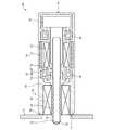
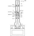
まず、本発明の一実施形態に係るアクチュエーターについて図面を参照しながら説明する。図1は、本発明の一実施形態に係るアクチュエーター100を模式的に示す断面図である。なお、図1では、ボールスプライン20、およびエンコーダー50を簡略化して図示している。1. 1. Actuator 1.1. Configuration of Actuator First, an actuator according to an embodiment of the present invention will be described with reference to the drawings. FIG. 1 is a cross-sectional view schematically showing an
アクチュエーター100は、図1に示すように、モーター部10と、ボールスプライン20と、滑りねじ部30と、ベアリング40,42と、エンコーダー50と、ケース60と、接触部70と、を含む。 As shown in FIG. 1, the
モーター部10は、マグネット12と、回転子14と、コイル16と、を含む。マグネット12は、ケース60の内周面に固定されている。マグネット12は、例えば、永久磁石である。回転子14は、ベアリング40,42を介して、ケース60に回転自在に支持されている。コイル16は、回転子14の外周面に固定されている。コイル16には、制御コントローラー(図示せず)から電流が供給される。モーター部10では、マグネット12で作られる磁界の中でコイル16に流れる電流に作用する力を利用して回転子14を回転させる。 The
回転子14の材質は、例えば、インバー合金である。インバー合金は、線膨張係数が小さい合金である。回転子14として用いられるインバー合金としては、36インバーが挙げられる。36インバーは、Fe−Ni合金であり、Niを36%含む。 The material of the
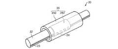
ボールスプライン20は、シャフト22と、ボール24と、軸受部26と、を含む。ボールスプライン20は、ストロークが有限である、有限ストロークのボールスプラインである。すなわち、ボールスプライン20は、ボール24を循環させるための機構(ボール循環路)を有していない。 The
図2は、ボールスプライン20を模式的に示す斜視図である。 FIG. 2 is a perspective view schematically showing the
シャフト22は、ボールスプライン20において、スプライン軸として機能する。シャフト22は、アクチュエーター100の出力軸である。シャフト22の先端部の外周面には、シャフト22の軸に沿った第1転動溝(スプライン溝)23が形成されている。第1転動溝23は、ボール24を転動させるための溝である。第1転動溝23は複数設けられるが、その数は特に限定されない。 The
ボール24は、第1転動溝23を転動可能である。第1転動溝23には、複数のボール24が配置され、第1転動溝23に配置されたボール24は、シャフト22の軸方向に並んだボール列を構成している。 The
軸受部26は、ケース60に固定されている。軸受部26は、ボール24を介して、シャフト22を支持している。軸受部26は、筒状の外筒(スプライン外筒)260と、保持器262と、を有している。外筒260は、ケース60の内周面に固定されている。外筒260には、シャフト22の第1転動溝23に対応する第2転動溝(図示せず)が形成されている。シャフト22の第1転動溝23と外筒260の第2転動溝との間にボール24が転動可能に介装されている。保持器262は、外筒260の内側に配置されている。保持器262は、ボール24を分離して保持している。 The bearing
軸受部26では、ボール24が保持器262によって保持されるため、ボール24が互いに接触しない。保持器262はボール24を循環させない非循環型の保持器であり、シャフト22の直線運動時に保持器262も移動するため、ストロークは有限となる。すなわち、ボールスプライン20では、ボール24は第1転動溝23上のみを転動し循環路等を転動しない。そのため、ボール24には常に一定の与圧が付与される。 In the bearing
シャフト22、ボール24、および軸受部26の材質は、金属である。シャフト22、ボール24、および軸受部26の材質は、例えば、ステンレス鋼である。 The material of the
シャフト22はボール24を介して軸受部26で支持されており、シャフト22の軸に沿って設けられた第1転動溝23をボール24が転動することで、シャフト22の軸回りの回転が抑制され、シャフト22は軸方向に直線運動する。 The
ボールスプライン20には、回転方向のすきまがなくなるように、与圧が付与されている。これにより、シャフト22の回転と振れの発生をより抑制することができる。したがって、アクチュエーター100では、駆動対象に軸方向の推進力のみを伝えることができる。 Pressurization is applied to the
滑りねじ部30は、モーター部10の回転子14の回転運動を、シャフト22の直線運動に変換する機構である。滑りねじ部30は、アクチュエーター100の出力軸(シャフト22)を出し入れする送り機構として機能する。滑りねじ部30は、図1に示すように、シャフト22と、ナット部32と、を含む。 The sliding
シャフト22の後端部には、雄ねじ山34が形成されている。ナット部32は、モーター部10の回転子14に固定されている。ナット部32には、シャフト22の雄ねじ山3
4に螺合する(かみ合う)雌ねじ山33が形成されている。ナット部32は、雌ねじ山33が形成されている部分ともいえる。A
A
ナット部32は、モーター部10の回転子14の回転に伴って回転し、ナット部32の雌ねじ山33とシャフト22の雄ねじ山34が螺合回転することによるねじの回転運動により、シャフト22を直線運動させる。 The
滑りねじ部30を構成するシャフト22の雄ねじ山34およびナット部32の雌ねじ山33は、ねじ研磨されていることが好ましい。これにより、滑りねじ部30は、より振動の少ないスムーズな挙動を示す。 It is preferable that the
ベアリング40,42は、ケース60に対して、回転子14を回転可能に支持する。ベアリング40は回転子14の先端側を支持し、ベアリング42は、回転子14の後端側を支持している。ここでは、2つのベアリング40,42で回転子14を回転可能に支持しているが、回転子14を支持するためのベアリング40,42の数や与圧の付与形態は特に限定されない。
エンコーダー50は、モーター部10の回転子14の回転速度や、回転方向、回転位置(角度)等を検出するためのセンサーである。エンコーダー50は、回転子14の回転速度や、回転方向、回転位置(角度)等を検出し、これらの情報を制御コントローラーに出力する。エンコーダー50は、ケース60の内側に配置されている。 The
ケース60は、モーター部10、ボールスプライン20、滑りねじ部30、ベアリング40,42、エンコーダー50を収容している。また、ケース60は、例えば、モーター部10のマグネット12の磁路を閉じ、磁気回路を構成している。ケース60には、モーター部10およびボールスプライン20が固定されている。 The
ケース60は、アクチュエーター100を支持するための支持部材2に固定されている。ケース60は、支持部材2に固定される固定部62を有している。固定部62は、ケース60のうち、支持部材2に固定される部分である。固定部62は、例えば、ねじ止めにより支持部材2に固定されてもよいし、接着剤などで支持部材2に固定されてもよい。 The
図示の例では、固定部62は、ケース60の先端61に設けられている。なお、固定部62の位置は、ケース60の後端63以外であれば、特に限定されない。 In the illustrated example, the fixing
ケース60の材質は、例えば、インバー合金である。ケース60として用いられるインバー合金としては、36インバーが挙げられる。ケース60の材質は、例えば、回転子14の材質と同じである。ケース60の材質として、インバー合金を用いることによって、ケース60の線膨張係数を小さくすることができ、かつ、ケース60が磁気回路を構成することができる。 The material of the
接触部70は、シャフト22の先端に設けられている。接触部70は、駆動対象に接触する部分である。アクチュエーター100では、シャフト22の先端に接触部70が設けられているため、シャフト22は、直接、駆動対象に接しない。接触部70の材質は、例えば、樹脂である。接触部70の熱伝導率は、シャフト22の熱伝導率よりも低い。例えば、接触部70の材質は、樹脂であり、シャフト22の材質は、金属である。 The
1.2. アクチュエーターの動作
アクチュエーター100では、制御コントローラーからモーター部10のコイル16に電流が供給されるとモーター部10の回転子14が回転する。モーター部10が回転駆動
すると、回転子14の回転力がナット部32を介してシャフト22の軸方向の推進力に変換される。すなわち、モーター部10の回転運動が、ナット部32とシャフト22からなる滑りねじ部30によって直線運動に変換される。シャフト22は、ボールスプライン20によって、軸回りの回転が抑制され、直線運動する。これにより、シャフト22、すなわち、アクチュエーター100の出力軸は、駆動対象にシャフト22の軸方向の推進力を伝える。1.2. Actuator operation In the
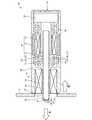
図3は、モーター部10が発生させる熱によるシャフト22の伸び、およびケース60の伸びを説明するための図である。 FIG. 3 is a diagram for explaining the elongation of the
モーター部10のコイル16に電流が供給されると、コイル16は熱を発生させる。モーター部10が発生させる熱によって、シャフト22は、シャフト22の軸に沿って、ナット部32から第1方向Aに伸びる。第1方向Aは、ナット部32からシャフト22の先端に向かう方向である。ナット部32は、シャフト22を支持しているため、シャフト22のナット部32で支持されている部分が、シャフト22の固定端となる。そのため、モーター部10が発生させる熱によって、シャフト22は、ナット部32から第1方向Aに伸びる。 When an electric current is supplied to the
また、モーター部10が発生させる熱によって、ケース60は、シャフト22の軸に沿って、固定部62から第2方向Bに伸びる。第2方向Bは、第1方向Aとは反対方向である。第2方向Bは、ケース60の固定部62からケース60の後端63に向かう方向である。ケース60の固定部62が、ケース60の固定端となる。そのため、モーター部10が発生させる熱によって、ケース60は、固定部62から第2方向Bに伸びる。ケース60が第2方向Bに伸びることによって、シャフト22は第2方向Bに移動する。 Further, due to the heat generated by the
モーター部10が発生させる熱によるシャフト22の第1方向Aの伸び量L2と、モーター部10が発生させる熱によるケース60の第2方向Bの伸びによるシャフト22の第2方向Bの移動量L4とは、等しい。したがって、アクチュエーター100では、シャフト22の伸び量L2とケース60の伸びによるシャフト22の移動量L4との差がゼロとなり、シャフト22の伸びをケース60の伸びによって相殺できる。したがって、モーター部10が発生させる熱によるシャフト22の先端の位置の変位を低減できる。 The amount of extension L2 of the
なお、シャフト22の第1方向Aの伸び量L2と、ケース60の伸びによるシャフト22の移動量L4との差は、ゼロでなくてもよく、駆動対象のドリフトが許容される範囲内であればよい。 The difference between the extension amount L2 of the
アクチュエーター100では、ケース60の固定部62の位置、およびアクチュエーター100を構成する各部の線膨張係数を最適化することによって、上記のようにシャフト22の先端の位置の変位を低減できる。 In the
温度の変化による物体の伸び量ΔLは、次式で表される。 The amount of elongation ΔL of the object due to the change in temperature is expressed by the following equation.
ΔL=α×L×ΔT
なお、αは、物体の線膨張係数であり、Lは物体のもとの長さであり、ΔTは物体の温度の変化量である。ΔL = α × L × ΔT
Α is the coefficient of linear expansion of the object, L is the original length of the object, and ΔT is the amount of change in the temperature of the object.
例えば、シャフト22の長さ(固定端からの長さ)、ケース60の長さ(固定端からの長さ)、およびモーター部10からシャフト22に加わる熱およびモーター部10からケース60に加わる熱を考慮して、ケース60の線膨張係数、およびシャフト22の線膨張係数を決定する。これにより、シャフト22の伸びによるシャフト22の先端の変位をケ
ース60の伸びで低減できる。例えば、ケース60の線膨張係数を、シャフト22の線膨張係数よりも小さくすることによって、シャフト22の伸びによるシャフト22の先端の変位をケース60の伸びで低減する。具体的には、ケース60の材質を線膨張係数の小さい36インバーとし、シャフト22の材質をインバー合金に比べて線膨張係数の大きいステンレス鋼とする。なお、ケース60の材質とシャフト22の材質の組み合わせは、この例に限定されない。For example, the length of the shaft 22 (the length from the fixed end), the length of the case 60 (the length from the fixed end), and the heat applied to the
また、図3に示す例では、ケース60の固定部62がケース60の先端61であるが、ケース60の固定部62の位置を変えることによって、ケース60の伸びを調整してもよい。 Further, in the example shown in FIG. 3, the fixing
また、上記では、シャフト22の伸びを、ケース60の伸びで相殺する場合について説明したが、シャフト22の伸びを、ケース60の伸びに、アクチュエーター100を構成するその他の部材の伸びを加えることによって、相殺してもよい。例えば、シャフト22の伸びを、ケース60の伸びおよび回転子14の伸びによって相殺してもよい。 Further, in the above description, the case where the elongation of the
1.3. 効果
アクチュエーター100では、モーター部10と、第1転動溝23が形成されたシャフト22を備えた有限ストロークのボールスプライン20と、シャフト22に形成された雄ねじ山34に螺合する雌ねじ山33を備えモーター部10の回転力をシャフト22に伝達するナット部32と、を含む。このようにアクチュエーター100では、ボールスプライン20のシャフト22を出力軸として用いることで、出力軸の出し入れ時にシャフト22の軸方向の推進力のみを駆動対象に伝えることができる。1.3. Effect In the
また、アクチュエーター100では、有限ストロークのボールスプライン20を用いている。すなわち、ボールスプライン20は、ボール24の循環路を有しておらず、ボールに付与される与圧を一定にすることができる。そのため、ボール24に付与される与圧が変化することにより発生する振動を生じさせないことができる。したがって、アクチュエーター100では、動作時のシャフト22の振動を低減することができる。これにより、駆動対象に推進力を与える際に生じる振動を低減することができ、例えば駆動対象に振動を生じさせることなく、推進力を与えることができる。 Further, the
例えば、ボールスプラインが、ボール循環路を備えた無限循環式のボールスプラインである場合、ボールが循環路と転動溝との間を移動する際にボールに付与される与圧が変化してシャフトが振動してしまう場合がある。これに対して、アクチュエーター100では、上述したように、ボール24の循環路を有していないため、ボール24に付与される与圧を一定にすることができ、シャフト22の振動を低減することができる。 For example, when the ball spline is an infinite circulation type ball spline provided with a ball circulation path, the pressurization applied to the ball when the ball moves between the circulation path and the rolling groove changes to change the shaft. May vibrate. On the other hand, since the
また、アクチュエーター100では、モーター部10の回転力を推進力に変換する機構として、滑りねじ部30を用いている。滑りねじ部30は、例えば、モーター部の回転力をボールねじシャフトの螺旋状の転動溝をボールが循環することで推進力に変換するボールねじを用いた場合と比べて、剛性が高く、さらに振動伝達効率が低い。また、ボールねじの動力伝達効率は、例えば90%以上である。そのため、アクチュエーター100では、モーター部10の磁気ヒステリシスによる微小な回転や、モーター部10を制御する制御コントローラーのサーボノイズによりモーター部10が意図せずに励起されることで発生する微小な振動等が、直接、シャフト22に伝わることを抑制することができる。 Further, in the
サーボノイズとは、位置偏差が無く、静定制御が完了している状態にも関わらず、アクチュエーターの電源ラインやエンコーダー制御ラインに電源やコンバーターからのリップルノイズや制御回路の駆動周波数成分等が混入し、コイルを意図せず励起、もしくは共振
させ、モーター部を極微小に震えさせてしまうことである。Servo noise means that even though there is no position deviation and static control is completed, ripple noise from the power supply and converter, drive frequency components of the control circuit, etc. are mixed in the power supply line and encoder control line of the actuator. However, the coil is unintentionally excited or resonated, causing the motor unit to quiver extremely minutely.
アクチュエーター100では、モーター部10の回転力をボールねじと比較して、ねじ部の送りピッチ(リード)を小さくできる滑りねじ部30で軸方向の推進力に変換しているため、シャフト22のストロークの全域で超微細な移動(例えばオングストロームオーダー)が可能である。さらに、アクチュエーター100では、例えばピエゾ素子を用いて駆動対象に推進力を与える場合と比べて、駆動対象を移動させることができる範囲を大きくすることができる。また、ピエゾ素子の膨張、収縮の過程は時間に対してリニアに応答させることが難しく静定に時間が掛かってしまうが、アクチュエーター100では、モーター部10の回転力をナット部32とシャフト22によって伝達しているため、剛性を高めることができ、静定時間を短くすることができる。 In the
アクチュエーター100では、減速機を必要としないため、減速機特有のバッククラッシュによる不感帯や部材のヒステリシスによる不安定な動作を招くことがなく、アクチュエーター100の最小駆動分解能付近での駆動を安定させることができる。 Since the
アクチュエーター100では、ボールスプライン20において、ボール24は第1転動溝23上のみを転動する。すなわち、ボールスプライン20は、ボール24を循環させる循環路を有しておらず、ボールに一定の与圧を付与することができる。したがって、アクチュエーター100では、上述したように、ボール24に付与される与圧が変化することにより発生する振動を生じさせないことができる。したがって、アクチュエーター100では、動作時のシャフト22の振動を低減することができる。これにより、駆動対象に推進力を与える際に生じる振動を低減することができ、例えば駆動対象に振動を生じさせることなく、推進力を与えることができる。 In the
アクチュエーター100では、モーター部10が発生させる熱によって、シャフト22は、シャフト22の軸に沿って第1方向Aに伸び、モーター部10が発生させる熱によって、ケース60は、シャフト22の軸に沿って、第1方向Aとは反対方向の第2方向Bに伸びる。そのため、アクチュエーター100では、モーター部10が発生させる熱によるシャフト22の伸びによるシャフト22の先端の変位を、モーター部10が発生させる熱によるケース60の伸びによって低減できる。したがって、アクチュエーター100では、駆動対象のドリフトを低減できる。 In the
アクチュエーター100では、シャフト22の先端に、接触部70が設けられている。接触部70の熱伝導率は、シャフト22の熱伝導率よりも低い。そのため、シャフト22の熱を駆動対象に伝わりにくくすることができる。これにより、シャフト22の熱が駆動対象に伝わることによるシャフト22の温度の変化を低減できる。この結果、シャフト22の温度変化とケース60の温度変化の差を小さくできる。そのため、シャフト22の伸びをケース60の伸びによって相殺する関係を維持できる。したがって、アクチュエーター100では、駆動対象のドリフトを低減できる。 In the
例えば、駆動対象の材質が熱伝導性のよい金属である場合、シャフト22の先端が、直接、駆動対象に接していると、シャフト22の熱が駆動対象に逃げて、シャフト22の温度がケース60の温度に比べて低下してしまう。この結果、シャフト22の伸びをケース60の伸びによって相殺する関係が崩れてしまい、シャフト22の先端の位置が変位してしまう。 For example, when the material of the drive target is a metal having good thermal conductivity, if the tip of the
これに対して、シャフト22の先端に接触部70が設けられていると、シャフト22の先端が、直接、駆動対象に接している場合と比べて、シャフト22の温度変化とケース60の温度変化の差を小さくできる。したがって、シャフト22の伸びをケース60の伸び
によって相殺する関係を維持できる。On the other hand, when the
このように、シャフト22の先端に、シャフト22よりも熱伝導率が低い接触部70が設けられることによって、駆動対象の材質(熱伝導率)によらず、シャフト22から駆動対象に逃げる熱を低減できる。そのため、上述したように、シャフト22の伸びをケース60の伸びによって相殺する関係を維持でき、駆動対象のドリフトを低減できる。 In this way, by providing the
アクチュエーター100では、モーター部10が発生させる熱によるシャフト22の第1方向Aの伸び量L2と、モーター部10が発生させる熱によるケース60の第2方向Bの伸びによるシャフト22の第2方向Bの移動量L4と、が等しい。そのため、アクチュエーター100では、シャフト22の伸びをケース60の伸びによって相殺できる。これにより、モーター部10が発生させる熱によるシャフト22の先端の位置の変位を低減でき、駆動対象のドリフトを低減できる。 In the
アクチュエーター100では、ケース60は、モーター部10の磁気回路を構成し、ケース60の材質はインバー合金である。そのため、アクチュエーター100では、モーター部10の熱によるケース60の伸びを低減しつつ、磁気回路を構成できる。 In the
アクチュエーター100では、回転子14の材質はインバー合金である。そのため、アクチュエーター100では、モーター部10の熱による回転子14の伸びを低減できる。 In the
2. 試料位置決め装置
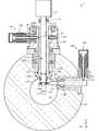
次に、本発明の一実施形態に係る試料位置決め装置について図面を参照しながら説明する。図4は本発明の一実施形態に係る試料位置決め装置1を模式的に示す図である。なお、図4では、試料ホルダー120をシフター110に装着した状態を示している。また、図4には、互いに直交する3つの軸としてX軸、Y軸、Z軸を図示している。以下、試料位置決め装置1の使用状態について説明する。なお、図示の例では、試料位置決め装置1は、透過電子顕微鏡(TEM)の試料位置決め装置である。2. Sample Positioning Device Next, a sample positioning device according to an embodiment of the present invention will be described with reference to the drawings. FIG. 4 is a diagram schematically showing a
試料位置決め装置1は、図4に示すように、シフター110と、試料ホルダー120と、シフター支持部材130と、X駆動機構140と、Y駆動機構150と、を含む。 As shown in FIG. 4, the
試料位置決め装置1は、試料Sを試料室101の所望の位置へ移動および静止させることができる。具体的には、試料位置決め装置1は、試料ホルダー120によって試料Sを支持し、駆動機構140,150によってX軸方向およびY軸方向に、試料Sを直線的に移動させることができる。また、試料位置決め装置1は、Z駆動機構(図示しない)によって、Z軸方向に試料Sを直線的に移動させてもよいし、傾斜機構(図示しない)によって、試料SをX軸周りに傾斜させてもよい。なお、図示の例において、Z軸方向は、試料室101を通過する電子線(図示しない)の進行方向である。 The
試料位置決め装置1では、シフター110は、壁部102を貫通するように設けられたシフター支持部材130によって支持されている。シフター110は、試料室101に連通する孔112を有しており、試料ホルダー120は、この孔112に移動可能に装着されている。試料ホルダー120は、試料Sが装着された先端部が試料室101に配置されている。そして、X駆動機構140は、試料ホルダー120を移動させることにより試料SをX軸方向に沿って移動させ、Y駆動機構150は、シフター110を回動させることにより試料SをY軸方向に沿って移動させる。 In the
以下、試料位置決め装置1を構成する各部材について説明する。 Hereinafter, each member constituting the
試料室101は、減圧状態に維持可能である。試料室101は、公知のポンプ(図示せず)によって真空排気されることにより減圧状態に維持される。試料室101には、試料ホルダー120によって試料Sが導入される。そして、試料室101において、試料Sに電子線が照射される。 The
シフター支持部材130は、壁部102を貫通する円筒状の部材である。シフター支持部材130には、シフター110が挿入されている。シフター支持部材130の試料室101側には、球面軸受部132が設けられている。球面軸受部132は、その内面が球面状に形成されている。 The
シフター110は、管状の部材であり、試料室101に連通する孔112を有している。図示の例では、孔112は、X軸方向に貫通している。孔112には、試料ホルダー120が装着される。これにより、試料ホルダー120は、Y軸方向およびZ軸方向の移動が規制され、X軸方向に直線的に移動可能となる。シフター110の内側には、試料ホルダー120を支持するベアリング114が設けられている。図示の例では、ベアリング114は、シフター110の両端部(孔112の開口付近)に設けられている。ベアリング114は、試料ホルダー120のX軸方向への移動を円滑にすることができる。 The
シフター110は、試料室101側の端部に、球面部116を有する。球面部116の表面は、中心が孔112の中心軸上にある球面状に形成されている。球面部116は、球面軸受部132により支持される。球面軸受部132は、その内面が球面部116の表面に接するように形成されている。これにより、球面部116は、球面軸受部132に摺動可能に支持される。そのため、シフター110は、球面部116の中心を回動中心として、回動することができる。球面部116と球面軸受部132との間には、試料室101を気密に封止するためのOリング119が設けられている。 The
試料ホルダー120は、シフター110の孔112に移動可能に装着される。試料ホルダー120の先端部には、試料Sを保持するための試料保持部123が設けられている。試料ホルダー120にはOリング122が装着され、試料ホルダー120とシフター110との間が気密に封止されている。Oリング122は、試料ホルダー120の移動に伴って、シフター110の孔112内を摺動する。 The
駆動機構140,150は、試料室101における試料ホルダー120の位置を変えることができる。具体的には、駆動機構140,150は、試料Sを試料室101の所望の位置へ移動および静止させるように、試料ホルダー120を動作させる。 The
X駆動機構140は、試料SをX軸方向に沿って移動させる。X駆動機構140は、アクチュエーター100を含む。X駆動機構140は、さらに、レバー142を含む。 The
レバー142は、軸143を回転中心とするてこ式のレバーである。レバー142の試料室101側の端部には、ベアリング144が設けられ、ベアリング144を介して試料ホルダー120を支持している。ベアリング144は、YZ平面内を転動することができる。そのため、試料SのY軸方向への移動が円滑になる。試料ホルダー120には、−X軸方向の力が働いているため、試料ホルダー120は、レバー142(ベアリング144)に押しつけられている。レバー142の試料室101側とは反対側の端部には、アクチュエーター100の接触部70が接している。 The
アクチュエーター100がシャフト22をX軸方向に直線的に移動させることにより、レバー142は、軸143を回転中心として回転し、試料ホルダー120(試料S)をX軸方向に直線的に移動させる。ベローズ146は、試料室101を減圧状態に保ちつつ、
レバー142の移動を円滑にすることができる。When the
The movement of the
Y駆動機構150は、試料SをY軸方向に移動させる。Y駆動機構150は、アクチュエーター100を含む。Y駆動機構150は、さらに、戻しばね152を含む。アクチュエーター100の接触部70は、シフター110の+Y軸方向側の外周面に接している。シフター110の−Y軸方向側の外周面には、戻しばね152が設けられている。シフター110は、戻しばね152によって、+Y軸方向に付勢されている。アクチュエーター100がシャフト22をY軸方向に直線的に移動させることにより、シフター110は、球面部116の中心を回動中心として回動する。これにより、試料SをY軸方向に直線的に移動させることができる。 The
なお、試料位置決め装置1は、試料SをZ軸方向に移動させるZ駆動機構(図示せず)をさらに有していてもよい。Z駆動機構は、Y駆動機構150と同様の構成であってもよい。また、試料位置決め装置1は、試料SをX軸まわりに傾斜させる機構(図示しない)を有していてもよい。 The
次に、試料位置決め装置1の動作について説明する。 Next, the operation of the
試料位置決め装置1では、X駆動機構140によって試料ホルダー120をX軸方向に移動させることにより、試料SをX軸方向に移動させる。具体的には、X駆動機構140を構成しているアクチュエーター100のシャフト22を出し入れすることでレバー142を回転させることにより、試料ホルダー120がX軸方向に直線的に移動し、試料SがX軸方向に移動する。 In the
また、試料位置決め装置1では、Y駆動機構150によってシフター110を移動させることにより、試料ホルダー120を移動させて、試料SをY軸方向に移動させる。具体的には、Y駆動機構150を構成しているアクチュエーター100のシャフト22を出し入れすることにより、シフター110を球面部116の中心を回動中心として回動させる。このシフター110の回動に伴って試料ホルダー120も回動し、試料SがY軸方向に移動する。 Further, in the
試料位置決め装置1は、例えば、以下の効果を有する。 The
試料位置決め装置1では、アクチュエーター100を含む。アクチュエーター100は、上述したように、アクチュエーター100の動作時のシャフト22の振動を低減することができる。そのため、試料位置決め装置1では、試料Sを移動させる際の試料Sの振動を低減することができる。したがって、例えば、試料位置決め装置1では、ユーザーは試料SをX軸方向(またはY軸方向)に移動させつつ、高倍率で試料Sを観察することができる。 The
また、試料位置決め装置1では、アクチュエーター100を含むため、上述したように、シャフト22のストロークの全域で超微細な移動(例えばオングストロームオーダー)が可能であり、例えばピエゾ素子を用いて駆動対象に推進力を与える場合と比べて、駆動対象を移動させることができる範囲を大きくすることができる。したがって、試料位置決め装置1では、例えば、φ2mmの試料Sの全域で超微細な移動(例えばオングストロームオーダー)が可能となる。これにより、例えば、試料Sの全域でのドリフト補正が可能となる。 Further, since the
したがって、試料位置決め装置1では、長時間のドリフト補正を必要とする元素マッピング、スペクトル解析、原子分析等の分析や、長距離でのドリフト補正を必要とする、加
熱、冷却、トモグラフ等のその場観察において、ドリフト補正のストローク切れ(ドリフト補正が可能な範囲から外れること)を無くすことができる。Therefore, in the
また、試料位置決め装置1では、アクチュエーター100を含むため、上述したように、例えばピエゾ素子を用いて駆動対象に推進力を与える場合と比べて、静定時間を短くすることができ、試料Sのドリフトの終息を早めることができる。 Further, since the
また、試料位置決め装置1では、アクチュエーター100の接触部70がレバー142に接しているため、シャフト22の熱をレバー142に伝わりにくくすることができる。この結果、上述したように、試料のドリフトを低減できる。 Further, in the
また、試料位置決め装置1では、アクチュエーター100の接触部70がシフター110に接しているため、シャフト22の熱をシフター110に伝わりにくくすることができる。この結果、上述したように、試料のドリフトを低減できる。 Further, in the
3. 電子顕微鏡
次に、本発明の一実施形態に係る電子顕微鏡について図面を参照しながら説明する。図5は、本発明の一実施形態に係る電子顕微鏡1000の構成を示す図である。図5は、試料Sが試料室101に導入された状態を図示している。3. 3. Electron Microscope Next, an electron microscope according to an embodiment of the present invention will be described with reference to the drawings. FIG. 5 is a diagram showing a configuration of an
電子顕微鏡1000は、例えば、透過電子顕微鏡(TEM)の構成を有している。電子顕微鏡1000は、試料位置決め装置1を含む。 The
電子顕微鏡1000は、さらに、電子線源1011と、集束レンズ1012と、対物レンズ1013と、中間レンズ1015と、投影レンズ1016と、撮像部1017と、コンデンサー絞り1020と、コンデンサー絞り位置決め装置1022と、対物絞り1030と、対物絞り位置決め装置1032と、制限視野絞り1040と、制限視野絞り位置決め装置1042と、を含む。 The
電子線源1011は、電子線EBを発生させる。集束レンズ1012は、電子線源1011で発生した電子線EBを集束して試料Sに照射するためのレンズである。対物レンズ1013は、試料Sを透過した電子線EBで結像するための初段のレンズである。 The
試料位置決め装置1は、上述したように、試料室101において試料ホルダー120に保持された試料Sの位置決めを行う。試料位置決め装置1は、アクチュエーター100を備えた駆動機構140,150によって試料Sを水平方向(電子線EBの進行方向に対して直交する方向)に移動させることができる。 As described above, the
中間レンズ1015および投影レンズ1016は、対物レンズ1013によって結像された像をさらに拡大し、撮像部1017に結像させる。電子顕微鏡1000では、対物レンズ1013、中間レンズ1015、および投影レンズ1016によって、結像系が構成されている。 The
撮像部1017は、結像系によって結像された透過電子顕微鏡像を撮影する。撮像部1017は、例えば、CCDカメラやCMOSカメラ等のデジタルカメラである。 The
コンデンサー絞り1020は、例えば、集束レンズ1012と対物レンズ1013との間に配置されている。コンデンサー絞り1020は、例えば、試料Sに照射される電子線EBの照射角(開き角)や照射量を調整することができる。コンデンサー絞り1020は、真空外から絞りの穴径の選択や位置の調整ができる可動絞りである。 The
コンデンサー絞り位置決め装置1022は、コンデンサー絞り1020を移動させて、絞りの穴径の選択や位置の調整を行うための装置である。コンデンサー絞り位置決め装置1022は、駆動源として、アクチュエーター100を備えている。これにより、コンデンサー絞り1020に振動を生じさせることなく、微細に移動させることができる。したがって、コンデンサー絞り1020を正確に位置決めすることができる。さらに、例えば、コンデンサー絞り1020を移動させた後のドリフトの終息を早めることができる。 The condenser
対物絞り1030は、対物レンズ1013の後焦点面に配置されている。対物絞り1030は、明視野像や暗視野像を得るための透過波や回折波を取り込むための絞りである。対物絞り1030は、真空外から絞りの穴径の選択や位置の調整ができる可動絞りである。 The
対物絞り位置決め装置1032は、対物絞り1030を移動させて、絞りの穴径の選択や位置の調整を行うための装置である。対物絞り位置決め装置1032は、駆動源として、アクチュエーター100を備えている。これにより、対物絞り1030に振動を生じさせることなく、微細に移動させることができる。したがって、対物絞り1030を正確に位置決めすることができる。さらに、例えば、対物絞り1030を移動させた後のドリフトの終息を早めることができる。 The objective
制限視野絞り1040は、対物レンズ1013の像面(中間レンズ1015の物面)に配置されている。制限視野絞り1040は、制限視野回折を行う際に、回折図形を得る試料Sの領域を制限する絞りである。制限視野絞り1040は、真空外から絞りの穴径の選択や位置の調整ができる可動絞りである。 The selected
制限視野絞り位置決め装置1042は、制限視野絞り1040を移動させて、絞りの穴径の選択や位置の調整を行うための装置である。制限視野絞り位置決め装置1042は、駆動源として、アクチュエーター100を備えている。これにより、制限視野絞り1040に振動を生じさせることなく、微細に移動させることができる。したがって、制限視野絞り1040を正確に位置決めすることができる。さらに、例えば、制限視野絞り1040を移動させた後のドリフトの終息を早めることができる。 The selected area
4. 変形例
なお、本発明は上述した実施形態に限定されず、本発明の要旨の範囲内で種々の変形実施が可能である。4. Modifications The present invention is not limited to the above-described embodiment, and various modifications can be carried out within the scope of the gist of the present invention.
例えば、上述した実施形態では、図1に示すように、アクチュエーター100のモーター部10は、マグネット12と、回転子14と、コイル16と、を備えていたが、モーター部10の構成はこの例に限定されない。モーター部10は、ACサーボモーター、DCサーボモーター、ステッピングモーター等の磁気型モーターであってもよい。すなわち、アクチュエーター100は、磁気型のモーター部10の回転力を、推進力に変換するリニアアクチュエーターに適用することができる。 For example, in the above-described embodiment, as shown in FIG. 1, the
例えば、上述した実施形態では、図4に示すように、アクチュエーター100を電子顕微鏡の試料位置決め装置1や、図5に示すように、絞り位置決め装置1022,1032,1042に適用した例について説明したが、アクチュエーター100を電子顕微鏡の検出器(例えばEDS検出器、暗視野検出器等)を移動させて位置決めを行うための検出器位置決め装置として用いてもよい。 For example, in the above-described embodiment, an example in which the
また、例えば、上述した実施形態では、試料位置決め装置1を透過電子顕微鏡(TEM
)に適用した場合について説明したが、試料位置決め装置1は、透過電子顕微鏡(TEM)に限らず、その他の荷電粒子線装置に適用することができる。このような荷電粒子線装置としては、例えば、走査電子顕微鏡(SEM)、透過電子顕微鏡(TEM)、および走査透過電子顕微鏡(STEM)等を含む電子顕微鏡や、集束イオンビーム装置(FIB装置)、電子ビーム露光装置等が挙げられる。Further, for example, in the above-described embodiment, the
) Has been described, but the
なお、上述した実施形態及び変形例は一例であって、これらに限定されるわけではない。例えば各実施形態及び各変形例は、適宜組み合わせることが可能である。 The above-described embodiments and modifications are merely examples, and the present invention is not limited thereto. For example, each embodiment and each modification can be combined as appropriate.
本発明は、実施の形態で説明した構成と実質的に同一の構成(例えば、機能、方法および結果が同一の構成、あるいは目的及び効果が同一の構成)を含む。また、本発明は、実施の形態で説明した構成の本質的でない部分を置き換えた構成を含む。また、本発明は、実施の形態で説明した構成と同一の作用効果を奏する構成又は同一の目的を達成することができる構成を含む。また、本発明は、実施の形態で説明した構成に公知技術を付加した構成を含む。 The present invention includes substantially the same configurations as those described in the embodiments (eg, configurations with the same function, method and result, or configurations with the same purpose and effect). The present invention also includes a configuration in which a non-essential part of the configuration described in the embodiment is replaced. The present invention also includes a configuration that exhibits the same effects as the configuration described in the embodiment or a configuration that can achieve the same object. The present invention also includes a configuration in which a known technique is added to the configuration described in the embodiment.
1…試料位置決め装置、2…支持部材、10…モーター部、12…マグネット、14…回転子、16…コイル、20…ボールスプライン、22…シャフト、23…第1転動溝、24…ボール、26…軸受部、30…滑りねじ部、32…ナット部、33…雌ねじ山、34…雄ねじ山、40…ベアリング、42…ベアリング、50…エンコーダー、60…ケース、70…接触部、100…アクチュエーター、101…試料室、102…壁部、110…シフター、112…孔、114…ベアリング、116…球面部、119…Oリング、120…試料ホルダー、122…Oリング、123…試料保持部、130…シフター支持部材、132…球面軸受部、140…X駆動機構、142…レバー、143…軸、144…ベアリング、146…ベローズ、150…Y駆動機構、152…戻しばね、200…アクチュエーター、202…表面、204…表面、260…外筒、262…保持器、1000…電子顕微鏡、1011…電子線源、1012…集束レンズ、1013…対物レンズ、1015…中間レンズ、1016…投影レンズ、1017…撮像部、1020…コンデンサー絞り、1022…コンデンサー絞り位置決め装置、1030…対物絞り、1032…対物絞り位置決め装置、1040…制限視野絞り、1042…制限視野絞り位置決め装置1 ... sample positioning device, 2 ... support member, 10 ... motor part, 12 ... magnet, 14 ... rotor, 16 ... coil, 20 ... ball spline, 22 ... shaft, 23 ... first rolling groove, 24 ... ball, 26 ... Bearing, 30 ... Sliding screw, 32 ... Nut, 33 ... Female thread, 34 ... Male thread, 40 ... Bearing, 42 ... Bearing, 50 ... Encoder, 60 ... Case, 70 ... Contact, 100 ... Actuator , 101 ... Sample chamber, 102 ... Wall, 110 ... Shifter, 112 ... Hole, 114 ... Bearing, 116 ... Spherical part, 119 ... O ring, 120 ... Sample holder, 122 ... O ring, 123 ... Sample holding part, 130 ... shifter support member, 132 ... spherical bearing, 140 ... X drive mechanism, 142 ... lever, 143 ... shaft, 144 ... bearing, 146 ... bellows, 150 ... Y drive mechanism, 152 ... return spring, 200 ... actuator, 202 ... Surface, 204 ... Surface, 260 ... Outer cylinder, 262 ... Cage, 1000 ... Electron microscope, 1011 ... Electron source, 1012 ... Focusing lens, 1013 ... Objective lens, 1015 ... Intermediate lens, 1016 ... Projection lens, 1017 ... Imaging Unit, 1020 ... Condenser bearing, 1022 ... Condenser bearing positioning device, 1030 ... Objective throttle, 1032 ... Objective throttle positioning device, 1040 ... Limited field aperture, 1042 ... Limited field aperture positioning device
Claims (7)
Translated fromJapanese軸に沿って移動可能なシャフトを備えた有限ストロークのボールスプラインと、
前記シャフトに形成された雄ねじ山に螺合する雌ねじ山を備え、前記モーター部の回転力を前記シャフトに伝達するナット部と、
前記モーター部および前記ボールスプラインが固定されたケースと、
を含み、
前記ケースは、支持部材に固定される固定部を有し、
前記モーター部が発生させる熱によって、前記シャフトは、前記シャフトの軸に沿って前記ナット部から第1方向に伸び、
前記モーター部が発生させる熱によって、前記ケースは、前記シャフトの軸に沿って、前記固定部から前記第1方向とは反対方向の第2方向に伸び、
前記シャフトの先端には、駆動対象に接触する接触部が設けられ、
前記接触部の熱伝導率は、前記シャフトの熱伝導率よりも低い、アクチュエーター。With the motor part
A finite stroke ball spline with a shaft that can move along the axis,
A nut portion having a female screw thread screwed into a male thread formed on the shaft and transmitting the rotational force of the motor portion to the shaft, and a nut portion.
A case in which the motor unit and the ball spline are fixed, and
Including
The case has a fixing portion that is fixed to a support member.
Due to the heat generated by the motor portion, the shaft extends in the first direction from the nut portion along the axis of the shaft.
Due to the heat generated by the motor portion, the case extends from the fixed portion in a second direction opposite to the first direction along the axis of the shaft.
A contact portion that comes into contact with the drive target is provided at the tip of the shaft.
An actuator in which the thermal conductivity of the contact portion is lower than the thermal conductivity of the shaft.
前記ケースは、磁気回路を構成し、
前記ケースの材質は、インバー合金である、アクチュエーター。In claim 1,
The case constitutes a magnetic circuit and
The material of the case is an actuator, which is an Invar alloy.
前記シャフトの材質は、金属であり、
前記接触部の材質は、樹脂である、アクチュエーター。In claim 1 or 2,
The material of the shaft is metal,
The material of the contact portion is an actuator, which is a resin.
前記モーター部が発生させる熱による前記シャフトの前記第1方向の伸び量と、前記モーター部が発生させる熱による前記ケースの前記第2方向の伸びによる前記シャフトの前記第2方向の移動量とは、等しい、アクチュエーター。In any one of claims 1 to 3,
The amount of extension of the shaft in the first direction due to the heat generated by the motor unit and the amount of movement of the shaft in the second direction due to the extension of the case in the second direction due to the heat generated by the motor unit are , Equal, actuator.
前記ボールスプラインは、
外筒と、
前記軸に沿って前記シャフトに設けられた第1転動溝と、前記軸に沿って前記外筒に設けられた第2転動溝と、の間に転動可能に配置されている複数のボールと、
複数の前記ボールを前記第1転動溝と前記第2転動溝に沿って分離して保持し、前記シャフトの移動に伴って移動する保持器と、
を有する、アクチュエーター。In any one of claims 1 to 4,
The ball spline is
With the outer cylinder
A plurality of rollable arrangements are arranged between a first rolling groove provided on the shaft along the shaft and a second rolling groove provided on the outer cylinder along the shaft. With the ball
A cage that separates and holds a plurality of the balls along the first rolling groove and the second rolling groove, and moves with the movement of the shaft.
Has an actuator.
請求項1ないし5のいずれか1項に記載のアクチュエーターを含む、試料位置決め装置。A sample positioning device that positions a sample in the sample chamber of a charged particle beam device.
A sample positioning device comprising the actuator according to any one of claims 1 to 5.
Priority Applications (3)
| Application Number | Priority Date | Filing Date | Title |
|---|---|---|---|
| JP2019212112AJP2021085410A (en) | 2019-11-25 | 2019-11-25 | Actuator, specimen positioning device, and charged particle beam apparatus |
| EP20208673.2AEP3825578A1 (en) | 2019-11-25 | 2020-11-19 | Actuator, sample positioning device, and charged particle beam system |
| US17/101,110US20210156457A1 (en) | 2019-11-25 | 2020-11-23 | Actuator, Sample Positioning Device, and Charged Particle Beam System |
Applications Claiming Priority (1)
| Application Number | Priority Date | Filing Date | Title |
|---|---|---|---|
| JP2019212112AJP2021085410A (en) | 2019-11-25 | 2019-11-25 | Actuator, specimen positioning device, and charged particle beam apparatus |
Publications (1)
| Publication Number | Publication Date |
|---|---|
| JP2021085410Atrue JP2021085410A (en) | 2021-06-03 |
Family
ID=73497631
Family Applications (1)
| Application Number | Title | Priority Date | Filing Date |
|---|---|---|---|
| JP2019212112APendingJP2021085410A (en) | 2019-11-25 | 2019-11-25 | Actuator, specimen positioning device, and charged particle beam apparatus |
Country Status (3)
| Country | Link |
|---|---|
| US (1) | US20210156457A1 (en) |
| EP (1) | EP3825578A1 (en) |
| JP (1) | JP2021085410A (en) |
Families Citing this family (1)
| Publication number | Priority date | Publication date | Assignee | Title |
|---|---|---|---|---|
| DE102023135833A1 (en) | 2023-12-19 | 2025-06-26 | Carl Zeiss Microscopy Gmbh | Particle beam system and method for operating a particle beam system |
Citations (6)
| Publication number | Priority date | Publication date | Assignee | Title |
|---|---|---|---|---|
| JPH01117847U (en)* | 1988-01-30 | 1989-08-09 | ||
| JPH0389873A (en)* | 1989-05-12 | 1991-04-15 | Fuji Electric Co Ltd | Actuator using piezoelectric element |
| JP2000317689A (en)* | 1999-05-17 | 2000-11-21 | Amada Eng Center Co Ltd | Method and structure for attaching motor mechanism in press |
| JP2004160565A (en)* | 2002-11-11 | 2004-06-10 | Canon Inc | Polishing method and variable shape polishing tool device |
| JP2014160788A (en)* | 2013-02-21 | 2014-09-04 | Panasonic Corp | Component mounting apparatus and component mounting method |
| JP2016084919A (en)* | 2014-10-29 | 2016-05-19 | 日本電子株式会社 | Actuator, sample positioning device, and charged particle beam device |
Family Cites Families (4)
| Publication number | Priority date | Publication date | Assignee | Title |
|---|---|---|---|---|
| JP2698069B2 (en)* | 1986-05-28 | 1998-01-19 | 日立精工株式会社 | Thermal displacement compensator for pole screw |
| JPH01311845A (en)* | 1988-06-09 | 1989-12-15 | Matsushita Electric Ind Co Ltd | Motor |
| JPH06300106A (en)* | 1993-04-10 | 1994-10-28 | T H K Kk | Electric actuator |
| JP6054728B2 (en)* | 2012-12-10 | 2016-12-27 | 日本電子株式会社 | Sample positioning device and charged particle beam device |
- 2019
- 2019-11-25JPJP2019212112Apatent/JP2021085410A/enactivePending
- 2020
- 2020-11-19EPEP20208673.2Apatent/EP3825578A1/ennot_activeWithdrawn
- 2020-11-23USUS17/101,110patent/US20210156457A1/ennot_activeAbandoned
Patent Citations (6)
| Publication number | Priority date | Publication date | Assignee | Title |
|---|---|---|---|---|
| JPH01117847U (en)* | 1988-01-30 | 1989-08-09 | ||
| JPH0389873A (en)* | 1989-05-12 | 1991-04-15 | Fuji Electric Co Ltd | Actuator using piezoelectric element |
| JP2000317689A (en)* | 1999-05-17 | 2000-11-21 | Amada Eng Center Co Ltd | Method and structure for attaching motor mechanism in press |
| JP2004160565A (en)* | 2002-11-11 | 2004-06-10 | Canon Inc | Polishing method and variable shape polishing tool device |
| JP2014160788A (en)* | 2013-02-21 | 2014-09-04 | Panasonic Corp | Component mounting apparatus and component mounting method |
| JP2016084919A (en)* | 2014-10-29 | 2016-05-19 | 日本電子株式会社 | Actuator, sample positioning device, and charged particle beam device |
Also Published As
| Publication number | Publication date |
|---|---|
| US20210156457A1 (en) | 2021-05-27 |
| EP3825578A1 (en) | 2021-05-26 |
Similar Documents
| Publication | Publication Date | Title |
|---|---|---|
| US20110253905A1 (en) | Specimen holder assembly | |
| JP4988662B2 (en) | Charged particle beam equipment | |
| JP6054728B2 (en) | Sample positioning device and charged particle beam device | |
| JP5798393B2 (en) | Transmission electron microscope system | |
| US8963102B2 (en) | Charged particle beam microscope, sample holder for charged particle beam microscope, and charged particle beam microscopy | |
| US9618101B2 (en) | Actuator, sample positioning device, and charged particle beam system | |
| CN108140525B (en) | Scanning transmission electron microscope with electron energy loss spectrometer and observation method thereof | |
| JP2021085410A (en) | Actuator, specimen positioning device, and charged particle beam apparatus | |
| US20110240881A1 (en) | Specimen holder and specimen holder movement device | |
| CN111566775B (en) | Electron microscope | |
| WO2014195998A1 (en) | Charged particle microscope, sample holder for charged particle microscope and charged particle microscopy method | |
| US9349569B2 (en) | Charged particle beam system | |
| CN111755304B (en) | Actuator assisted positioning system and method | |
| JP6009980B2 (en) | Holder, charged particle beam device, and vacuum device | |
| JP6421041B2 (en) | Charged particle beam equipment | |
| JP6823993B2 (en) | Support device and vacuum device | |
| JP2009081080A (en) | Eucentric sample holder in charged particle beam equipment | |
| JP2015220057A (en) | Sample holder | |
| JP7724552B2 (en) | Pole piece for transmission electron microscope | |
| JP2009158405A (en) | Analyzer using electron beam | |
| JPH03159048A (en) | Electron microscope | |
| JP2013157168A (en) | Sample holder support device |
Legal Events
| Date | Code | Title | Description |
|---|---|---|---|
| A621 | Written request for application examination | Free format text:JAPANESE INTERMEDIATE CODE: A621 Effective date:20201113 | |
| A977 | Report on retrieval | Free format text:JAPANESE INTERMEDIATE CODE: A971007 Effective date:20210903 | |
| A131 | Notification of reasons for refusal | Free format text:JAPANESE INTERMEDIATE CODE: A131 Effective date:20210928 | |
| A02 | Decision of refusal | Free format text:JAPANESE INTERMEDIATE CODE: A02 Effective date:20220322 |