JP2021081223A - Smart guide wire and guide wire operation system - Google Patents
Smart guide wire and guide wire operation systemDownload PDFInfo
- Publication number
- JP2021081223A JP2021081223AJP2019206595AJP2019206595AJP2021081223AJP 2021081223 AJP2021081223 AJP 2021081223AJP 2019206595 AJP2019206595 AJP 2019206595AJP 2019206595 AJP2019206595 AJP 2019206595AJP 2021081223 AJP2021081223 AJP 2021081223A
- Authority
- JP
- Japan
- Prior art keywords
- wire
- guide wire
- tip
- sensor
- rotation
- Prior art date
- Legal status (The legal status is an assumption and is not a legal conclusion. Google has not performed a legal analysis and makes no representation as to the accuracy of the status listed.)
- Withdrawn
Links
- 230000005291magnetic effectEffects0.000claimsabstractdescription88
- 239000013598vectorSubstances0.000claimsabstractdescription32
- 238000012545processingMethods0.000claimsdescription38
- 238000005452bendingMethods0.000claimsdescription33
- 238000001514detection methodMethods0.000claimsdescription13
- 230000002792vascularEffects0.000claimsdescription12
- 238000005516engineering processMethods0.000abstractdescription13
- 238000005259measurementMethods0.000description18
- 210000004204blood vesselAnatomy0.000description16
- 229910000734martensiteInorganic materials0.000description16
- 239000000758substrateSubstances0.000description15
- 229910001220stainless steelInorganic materials0.000description14
- 239000010935stainless steelSubstances0.000description14
- 238000011161developmentMethods0.000description12
- 238000000034methodMethods0.000description9
- 238000012360testing methodMethods0.000description9
- 230000006870functionEffects0.000description7
- 229910000889permalloyInorganic materials0.000description7
- 238000004364calculation methodMethods0.000description5
- 238000005482strain hardeningMethods0.000description5
- 230000001133accelerationEffects0.000description4
- WABPQHHGFIMREM-UHFFFAOYSA-Nlead(0)Chemical compound[Pb]WABPQHHGFIMREM-UHFFFAOYSA-N0.000description4
- BASFCYQUMIYNBI-UHFFFAOYSA-NplatinumChemical compound[Pt]BASFCYQUMIYNBI-UHFFFAOYSA-N0.000description4
- 238000003825pressingMethods0.000description4
- 229910018487Ni—CrInorganic materials0.000description3
- 239000000853adhesiveSubstances0.000description3
- 230000001070adhesive effectEffects0.000description3
- 229910000963austenitic stainless steelInorganic materials0.000description3
- 230000005347demagnetizationEffects0.000description3
- 230000005284excitationEffects0.000description3
- 238000003780insertionMethods0.000description3
- 230000037431insertionEffects0.000description3
- 229910052750molybdenumInorganic materials0.000description3
- 230000003014reinforcing effectEffects0.000description3
- 229910052804chromiumInorganic materials0.000description2
- 230000002708enhancing effectEffects0.000description2
- 239000000284extractSubstances0.000description2
- 238000007429general methodMethods0.000description2
- 229910052748manganeseInorganic materials0.000description2
- 229910052759nickelInorganic materials0.000description2
- NJPPVKZQTLUDBO-UHFFFAOYSA-NnovaluronChemical compoundC1=C(Cl)C(OC(F)(F)C(OC(F)(F)F)F)=CC=C1NC(=O)NC(=O)C1=C(F)C=CC=C1FNJPPVKZQTLUDBO-UHFFFAOYSA-N0.000description2
- 229910052697platinumInorganic materials0.000description2
- 229910052761rare earth metalInorganic materials0.000description2
- 150000002910rare earth metalsChemical class0.000description2
- 230000035945sensitivityEffects0.000description2
- 239000010409thin filmSubstances0.000description2
- 230000009466transformationEffects0.000description2
- 229910000859α-FeInorganic materials0.000description2
- 230000000740bleeding effectEffects0.000description1
- 239000003990capacitorSubstances0.000description1
- 239000002131composite materialSubstances0.000description1
- 239000002872contrast mediaSubstances0.000description1
- 229910052802copperInorganic materials0.000description1
- 230000007774longtermEffects0.000description1
- 239000000463materialSubstances0.000description1
- 230000002093peripheral effectEffects0.000description1
- 238000011160researchMethods0.000description1
- 239000011347resinSubstances0.000description1
- 229920005989resinPolymers0.000description1
- 239000004065semiconductorSubstances0.000description1
- 238000001356surgical procedureMethods0.000description1
- 230000001225therapeutic effectEffects0.000description1
- 238000002560therapeutic procedureMethods0.000description1
- 238000012549trainingMethods0.000description1
Images


Landscapes
- Force Measurement Appropriate To Specific Purposes (AREA)
- Measurement Of Length, Angles, Or The Like Using Electric Or Magnetic Means (AREA)
- Media Introduction/Drainage Providing Device (AREA)
Abstract
Description
Translated fromJapanese本発明は、生体内のセンサ内臓式のガイドワイヤと生体外部の磁気センサグリッド、センサデータ等から得られるセンサデータ処理装置およびその表示装置からなるスマートガイドワイヤ、およびガイドワイヤ操作システムとガイドワイヤ操作ロボットシステムに関するものである。 The present invention provides a smart guide wire including a guide wire with a built-in sensor in a living body, a magnetic sensor grid outside the living body, a sensor data processing device obtained from sensor data, and a display device thereof, and a guide wire operating system and guide wire operation. It is about robot systems.
カテーテル治療は、外科手術に代わって直接患部にカテーテルを挿入して治療する患者への負担が軽い手術で、急速に普及している。治療医師は、X線で血管マップを作成したマップ上に患部を特定し、その位置に向けてカテーテルを誘導する。治療医師はX線で血管マップ上のカテーテルの先端位置を見ながらカテーテルを操作する。
本治療において、X線の長時間照射および造影剤の投与による患者の身体への負担が問題となっている。また、治療医師等のX線被曝も問題となっている。そのためにロボット治療の技術開発が活発に取り組まれている(特許文献1、特許文献2)。Catheter treatment is an operation that places a light burden on patients who are treated by inserting a catheter directly into the affected area instead of surgery, and is rapidly becoming widespread. The treating doctor identifies the affected area on a map in which a blood vessel map is created by X-ray, and guides the catheter toward the position. The treating doctor operates the catheter while observing the position of the tip of the catheter on the blood vessel map with X-rays.
In this treatment, the burden on the patient's body due to long-term irradiation of X-rays and administration of a contrast medium has become a problem. In addition, exposure to X-rays by therapeutic doctors and the like has also become a problem. For this reason, technological development of robot therapy is being actively undertaken (
他方、ガイドワイヤは、直径が0.5から1mmと非常に小さいため、センサを内蔵して、カテーテルのような自律的誘導システムは開発されておらず、重要な開発課題となっている。特に小さなガイドワイヤの先端を±0.1mm程度の精度で位置決めする技術の開発が求められている。On the other hand, since the guide wire has a very small diameter of 0.5 to 1 mm, an autonomous guidance system such as a catheter with a built-in sensor has not been developed, which is an important development issue. In particular, the development of a technique for positioning the tip of a small guide wire with an accuracy of about ± 0.1 mm is required.
また、ガイドワイヤが血管を突き抜き出血トラブルが発生する場合があり、ガイドワイヤ先端にかかる接触力を求めることも求められている。小型で高感度の歪みゲージが半導体方式や応力インピーダンスセンサ(以下、SIセンサという。)を使って研究開発(非特許文献1)されているが、いまだにその開発に成功していない。In addition, the guide wire may penetrate a blood vessel and cause a bleeding trouble, and it is also required to obtain a contact force applied to the tip of the guide wire. A small and highly sensitive strain gauge has been researched and developed (Non-Patent Document 1) using a semiconductor method and a stress impedance sensor (hereinafter referred to as SI sensor), but the development has not been successful yet.
さらに、ガイドワイヤ先端は、手元ドライバーに負荷するトルクおよびトルカーの回転量で制御されるが、治療医師の経験と勘に頼って操作しているのが現状である。したがって長年の経験と高度な知識が必要で、治療医師の育成の障害となっている。ドライバイー側の制御パラメータの数値化、見える化とそれに対応したワイヤセンタの動きや血管との接触圧の数値化、見える化を進めて、治療医師の手術をより容易なものとすることが求められている。Further, the tip of the guide wire is controlled by the torque applied to the driver at hand and the amount of rotation of the torquer, but the current situation is that the guide wire is operated depending on the experience and intuition of the treating doctor. Therefore, many years of experience and advanced knowledge are required, which is an obstacle to the training of treating doctors. It is required to make the operation of the treating doctor easier by quantifying and visualizing the control parameters on the driver's side and quantifying and visualizing the movement of the wire center and the contact pressure with the blood vessel corresponding to it. Has been done.
これらのセンサを使って、すなわちワイヤの先端位置を特定し、さらにワイヤ先端と血管との接触圧、ドライバー側のトルクなど操作データを数値化、見える化をすることによって、治療医師をアシストし、手術操作を容易にして、X線画像への依存度を低め、X線照射時間を短縮することが期待されている。さらに、治療医師がワイヤ先端位置の移動位置を指示し、それに従ってガイドワイヤ先端を自動制御するロボット操作システムを確立することが期待されている。 Using these sensors, that is, by identifying the position of the tip of the wire and quantifying and visualizing operation data such as the contact pressure between the tip of the wire and the blood vessel and the torque on the driver side, the treatment doctor is assisted. It is expected that the surgical operation will be facilitated, the dependence on the X-ray image will be reduced, and the X-ray irradiation time will be shortened. Further, it is expected that a treating doctor will instruct the moving position of the wire tip position and establish a robot operation system that automatically controls the guide wire tip according to the movement position.
本発明の第1の課題は、
生体内(血管内)に挿入するワイヤ先端部、ドライバー部(ドライバー側とも言う。)および両者を連結するワイヤ連結部からなるガイドワイヤとそのガイドワイヤを操作する生体外部のデータ処理装置等からなるスマートガイドワイヤにおいて、
ガイドワイヤのワイヤ先端部に磁石および歪みゲージを備え、ドライバー部(ドライバー側)にはトルクセンサ、トルカー回転量計測装置およびドライバーの回転角度検出センサ、回転速度検出センサを備え、
生体外部に磁気ベクトルセンサグリッドと磁気ベクトルセンサグリッドのデータを使ってワイヤ先端の位置と方位を計算する位置センサデータ処理装置と、
ワイヤ先端の接触圧と曲げ応力、およびドライバー部のトルクと回転量およびドライバーの回転方位と回転速度を計算する応力センサデータ処理装置と回転(回転角度、回転速度)センサデータ処理装置と、計算して求めた計測値を表示する表示装置からなるセンサ内蔵式のスマートガイドワイヤを開発することである。The first object of the present invention is
It consists of a guide wire consisting of a wire tip to be inserted into the living body (inside a blood vessel), a driver part (also referred to as a driver side), and a wire connecting part connecting the two, and an external data processing device for operating the guide wire. In the smart guide wire
A magnet and a strain gauge are provided at the tip of the guide wire, and a torque sensor, a torquer rotation amount measuring device, a driver rotation angle detection sensor, and a rotation speed detection sensor are provided on the driver part (driver side).
A position sensor data processing device that calculates the position and orientation of the wire tip using the magnetic vector sensor grid and the data of the magnetic vector sensor grid outside the living body.
Calculated with stress sensor data processing device and rotation (rotation angle, rotation speed) sensor data processing device that calculates the contact pressure and bending stress of the wire tip, torque and rotation amount of the driver part, and the rotation direction and rotation speed of the driver. The purpose is to develop a smart guide wire with a built-in sensor, which consists of a display device that displays the measured values obtained.
上記本発明の第1課題を解決するためには、以下の5つの新要素技術開発を必要としている。
新要素技術開発の第1課題は、ワイヤ先端のステンレスに着目し、それを着磁してステンレス磁石とし、そこから発する磁界を生体外部の磁気ベクトルセンサグリッドシステムで検知し、センサグリッドのデータを使ってワイヤ先端の位置と方位を計算する位置センサデータ処理装置と計算して求めた位置・方位値を表示する表示装置からなるスマートガイドワイヤを開発することである。In order to solve the first problem of the present invention, the following five new elemental technologies are required to be developed.
The first issue in the development of new element technology is to focus on the stainless steel at the tip of the wire, magnetize it into a stainless steel magnet, detect the magnetic field generated from it with a magnetic vector sensor grid system outside the living body, and collect the sensor grid data. The purpose is to develop a smart guide wire consisting of a position sensor data processing device that calculates the position and orientation of the tip of the wire and a display device that displays the calculated position and orientation value.
新要素技術開発の第2課題は、サイズが幅0.2mmで長さが3mm程度の超小型サイズで、しかもゲージファクターが1000以上の高感度の歪みゲージを開発し、それをガイドワイヤの先端部に設置して、ワイヤ先端の接触圧および曲げ応力を検知することを可能にすることある。The second issue in the development of new element technology is to develop a highly sensitive strain gauge with a width of 0.2 mm and a length of about 3 mm, and a gauge factor of 1000 or more, and use it as the tip of the guide wire. It may be installed in the section to allow detection of contact pressure and bending stress at the tip of the wire.
新要素技術開発の第3課題は、ドライバー部のハンドルとトルカーにそれぞれトルクセンサを取り付けて、ハンドル上のトルクセンサでワイヤ先端の回転にかかる力を計測し、トルカーにかかるトルクでワイヤ挿入に負荷する押し付け力を計測し、さらに回転量計測装置でハンドルとトルカーの相対的な回転量を計測し、その回転量からワイヤの送り量を算出することである。そのために、小型で高感度なひねりゲージおよび小型で微小回転角度を検出できる回転量計測装置を開発することである。The third issue in the development of new element technology is to attach torque sensors to the handle and torquer of the driver, measure the force applied to the rotation of the wire tip with the torque sensor on the handle, and load the wire insertion with the torque applied to the torquer. The pressing force is measured, the relative rotation amount of the handle and the torquer is measured by the rotation amount measuring device, and the wire feed amount is calculated from the rotation amount. To this end, we will develop a compact and highly sensitive twist gauge and a compact and small rotation amount measuring device that can detect minute rotation angles.
新要素技術開発の第4課題は、ドライバー部のハンドルにモーションセンサを取り付けて、ハンドルの回転方位、回転量および回転速度を検知することである。そのために、電子コンパスの方位精度を5度から0.1度程度に改善して、電子コンパス、3軸加速度センサおよびジャイロセンサを融合した複合センサの方位精度を10度程度から1度以下へと改善することである。The fourth task of developing new element technology is to attach a motion sensor to the handle of the driver unit to detect the rotation direction, the amount of rotation, and the rotation speed of the handle. Therefore, the directional accuracy of the electronic compass has been improved from about 5 degrees to about 0.1 degrees, and the directional accuracy of the composite sensor that combines the electronic compass, 3-axis accelerometer and gyro sensor has been reduced from about 10 degrees to 1 degree or less. To improve.
本発明の第2の課題は、
上記センサ内蔵式のスマートガイドワイヤとX線画像から求めた血管網マップと 血管網マップ上に治療患部位置を指定するマーキングシステムと任意の時刻におけるガイドワイヤ先端位置を治療医師に伝達えるシステムと次の時刻における、つまり所定の時間間隔後における次の目標位置へガイドワイヤ先端を誘導するのに必要なトルクとワイヤ押し込み量と回転角を計算して治療医師に伝達するシステムと、この操作を繰り返して治療医師が最終的にスマートガイドワイヤを治療患部位置まで誘導する治療をアシストするガイドワイヤ操作アシストシステムを開発することである。The second object of the present invention is
The smart guide wire with built-in sensor, the vascular network map obtained from the X-ray image, the marking system that specifies the position of the affected area on the vascular network map, and the system that can convey the tip position of the guide wire to the treating doctor at any time, and the next This operation is repeated with a system that calculates the torque, wire pushing amount, and rotation angle required to guide the guide wire tip to the next target position at the time of, that is, after a predetermined time interval, and transmits it to the treating doctor. The treatment doctor will finally develop a guide wire operation assist system that assists the treatment in guiding the smart guide wire to the position of the affected area.
本発明の第3の課題は、
上記ガイドワイヤ操作アシストシステムにおいて、ドライバーの操作を治療医師に代えてロボット操作システムにするガイドワイヤ操作ロボットシステムを開発することである。The third object of the present invention is
In the guide wire operation assist system, it is to develop a guide wire operation robot system in which the driver's operation is changed to a robot operation system instead of the treating doctor.
本発明の第1課題を解決するために、5つの新要素技術を開発した。
新要素技術開発の第1の課題は、ワイヤの先端のステンレスに着目し、それを着磁してステンレス磁石とし、そこから発する磁界を外部の磁気ベクトルセンサグリッドシステムで検知し、センサグリッドのデータを使ってワイヤ先端の位置と方位を計算するセンサデータ処理装置と計算して求めた位置・方位値を表示する表示装置(位置・方位表示装置)からなるスマートガイドワイヤを開発した。
ここで、ワイヤの先端のステンレスは、コアワイヤ、スプリングコイルおよび補強コイルからなっている。In order to solve the first problem of the present invention, five new elemental technologies have been developed.
The first issue in the development of new element technology is to focus on the stainless steel at the tip of the wire, magnetize it into a stainless steel magnet, detect the magnetic field generated from it with an external magnetic vector sensor grid system, and perform sensor grid data. We have developed a smart guide wire consisting of a sensor data processing device that calculates the position and orientation of the tip of the wire and a display device (position / orientation display device) that displays the calculated position / orientation value.
Here, the stainless steel at the tip of the wire is composed of a core wire, a spring coil and a reinforcing coil.
ワイヤの先端部は、Ni−Cr系(オーステナイト系)非磁性ステンレスを50%以上の加工度で強加工して素材の強度を大きくしてばね性を強くしたものである。オーステナイト系ステンレス鋼のオーステナイト層の安定度の物差しであるMd点をCr量、Ni量を適切に調整して、−50℃〜100℃となるように調整する。そして、常温下で50%〜90%の冷間加工を行なうことにより50〜95%のマルテンサイト量を確保する。また、低温で加工するとマルテンサイト変態は容易に生じるので、40%程度の低加工度で多くのマルテンサイト相を得る必要がある場合、−40℃程度の低温で加工することが望ましい。
なお、Md点とは、30%の冷間加工を施した時に50%のマルテンサイト量が生じせしめる温度で、式(1)で示される。
Md30(℃)=413−462(%C+%N)−9.2(%Si)−8.1(%Mn)−13.7(%Cr)−9.5(%Ni)−6(%Cu)−18.5(%Mo) ・・・(1)The tip of the wire is made by strongly processing Ni-Cr-based (austenitic) non-magnetic stainless steel with a processing degree of 50% or more to increase the strength of the material and enhance the springiness. The Md point, which is a measure of the stability of the austenitic layer of austenitic stainless steel, is adjusted appropriately by adjusting the amount of Cr and the amount of Ni so as to be −50 ° C. to 100 ° C. Then, the amount of martensite of 50 to 95% is secured by performing cold working of 50% to 90% at room temperature. Further, since martensitic transformation easily occurs when processed at a low temperature, it is desirable to process at a low temperature of about -40 ° C when it is necessary to obtain a large number of martensite phases at a low processing degree of about 40%.
The Md point is a temperature at which 50% of martensite is generated when 30% of cold working is applied, and is represented by the formula (1).
Md30 (° C.) = 413-462 (% C +% N) -9.2 (% Si) -8.1 (% Mn) -13.7 (% Cr) -9.5 (% Ni) -6 (%) Cu) -18.5 (% Mo) ・ ・ ・ (1)
磁石特性は保磁力の大きさで評価できるので、保磁力とマルテンサイト量の関係について調べた。その結果を図1に示す。
本発明者らは、ステンレス磁石の保磁力は100〜1000Oe程度であることを確認した。この値はフェライト磁石や希土類磁石の保磁力の4k〜40kOeと比べてかなり小さいが、磁石形状を細長い形状として、パーミアンス係数を5以上とすることで、50Oe程以下の通常の磁界環境を想定する限り、その磁界による減磁を回避できることに思い至った。なお、磁石の動作点はパーミアンス係数P=L/D(L:磁石の長さ、D:磁石の直径)で決定されるものである。Since the magnet characteristics can be evaluated by the magnitude of the coercive force, the relationship between the coercive force and the amount of martensite was investigated. The result is shown in FIG.
The present inventors have confirmed that the coercive force of the stainless magnet is about 100 to 1000 Oe. This value is considerably smaller than the coercive force of 4k to 40kOe of ferrite magnets and rare earth magnets, but by making the magnet shape elongated and setting the permit coefficient to 5 or more, a normal magnetic field environment of about 50Oe or less is assumed. As long as I realized that I could avoid demagnetization due to the magnetic field. The operating point of the magnet is determined by the permeance coefficient P = L / D (L: length of magnet, D: diameter of magnet).
ワイヤの先端のステンレス磁石から発する磁界の測定結果の一例を図2に示す。
測定高さ(磁石からの距離)を最大150mmと想定すると、0.1mGという微小磁界を検知することが必要である。そこで、0.1mGという微小磁界を検知することができる高感度マイクロ3軸磁気センサグリッド、つまり磁気ベクトルセンサグリッド(センサグリッドという。)を開発した。このセンサグリッドで、任意の位置にある任意の方向に向いた磁石が発する磁界を検知し、そのセンサグリッドのデータを使ってワイヤ先端の位置と方位を計算することができる計算プログラムを作成した。FIG. 2 shows an example of the measurement result of the magnetic field generated from the stainless magnet at the tip of the wire.
Assuming that the maximum measurement height (distance from the magnet) is 150 mm, it is necessary to detect a minute magnetic field of 0.1 mG. Therefore, we have developed a high-sensitivity micro 3-axis magnetic sensor grid that can detect a minute magnetic field of 0.1 mG, that is, a magnetic vector sensor grid (referred to as a sensor grid). With this sensor grid, we created a calculation program that can detect the magnetic field generated by a magnet in any direction at an arbitrary position and calculate the position and orientation of the wire tip using the data from the sensor grid.
なお、ステンレス磁石から発生する磁界が不十分な場合、補助的に先端部の隙間に磁石を挿入することにより十分な磁界が得られる。When the magnetic field generated from the stainless steel magnet is insufficient, a sufficient magnetic field can be obtained by inserting the magnet into the gap at the tip as an auxiliary.
なお、磁石の測定位置X,Y,Zおよび磁石の向きΘ、φを求める計算原理は、一般的方法としては、所定の位置で所定の向きに向いた磁石から発する磁界を各磁気ベクトルセンサ位置における磁界理論値と磁界実測値の差をεij誤差として、誤差関数Eij=Σ(εij)2を作成し、それを各測定位置Xij,Yij,Zijで偏微分して、誤差関数が最小値を取るとして、連立方程式を求め、それらの式を使って磁石の測定位置X,Y,Zおよび磁石の向きΘ、φを計算して求めることできることが知られている。The calculation principle for determining the measurement positions X, Y, Z of the magnet and the directions Θ, φ of the magnet is, as a general method, the magnetic field generated from the magnet oriented in the predetermined direction at the predetermined position at each magnetic vector sensor position.An error function Eij = Σ (εij) 2 is created with the difference between the magnetic field theoretical value and the magnetic field measured value in the above as the εij error, and it is partially differentiated at each measurement position Xij, Yij, Zij, and the error function sets the minimum value. It is known that simultaneous equations can be obtained, and the measurement positions X, Y, Z of the magnet and the directions Θ, φ of the magnet can be calculated and obtained using these equations.
新要素技術開発の第2の課題を解決するために、歪みゲージとしては、非特許文献1に記載されたSIセンサに着目した。SIセンサの小型化は、非特許文献1のデータを参考にして、鋭意研究した結果、SI素子のアモルファスワイヤの長さ30mmから3mm以下とし、アモルファスワイヤの直径を30μmから10μmへと細径化し、さらに、励磁周波数を20MHzから200MHzへと増加させることによって、長さ2mm程度で、かつ1000以上のひずみゲージ率を有するSIセンサを実現できることを見出した。In order to solve the second problem of new element technology development, we focused on the SI sensor described in
つぎに、SI素子を被試験体の簡単に取り付けることができる構造を考案した。本構造の特徴は、フレキシブル基板上に、表面に応力検知体であるアモルファス磁歪ワイヤ(以下、磁歪ワイヤという。)と磁歪ワイヤの両端にある磁歪ワイヤ電極を備えたもので、容易に基板表面を被試験体の表面部に接着剤で固定することができる。Next, we devised a structure that allows the SI element to be easily attached to the test piece. The feature of this structure is that the surface of the flexible substrate is provided with an amorphous magnetostrictive wire (hereinafter referred to as a magnetostrictive wire) which is a stress detector and magnetostrictive wire electrodes at both ends of the magnetostrictive wire. It can be fixed to the surface of the test piece with an adhesive.
さらに、SI素子は、歪みと同時に外部磁界の影響を受けるので、磁歪ワイヤをパーマロイで環状に囲って磁気シールドすることにした。
本知見をもとに、作成したSI素子の形状を図3に示す。典型的なサイズは、幅は0.2mmで、長さは2mmである。電極はワイヤ両端のワイヤ端子と外部接続用の電極端子2個である。外周部はパーマロイ薄膜で囲い磁気シールドする構造となっている。ただし、ガイドワイヤのサイズは多様であるので、取り付け可能なサイズならば上記数値に限定されるものではない。Further, since the SI element is affected by the external magnetic field at the same time as the strain, it is decided to magnetically shield the magnetostrictive wire by enclosing it in a ring shape with permalloy.
The shape of the SI element created based on this finding is shown in FIG. Typical sizes are 0.2 mm wide and 2 mm long. The electrodes are wire terminals at both ends of the wire and two electrode terminals for external connection. The outer circumference is surrounded by a permalloy thin film and magnetically shielded. However, since the size of the guide wire varies, the size is not limited to the above value as long as it can be attached.
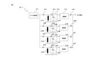
SIセンサの回路としては、図4に示すように、磁歪ワイヤにパルス電流を通電するパルス発振器と、磁歪ワイヤに生じる歪量に対応したインピーダンス変化を磁歪ワイヤ電圧変化として取り出してサンプルホールドするサンプルホールド回路と、ホールド電圧を増幅して出力する増幅回路とからなっている。なお、磁歪ワイヤ電圧は積分回路方式、インピーダンスアナライザ方式など電子回路でも検出可能である。As a circuit of the SI sensor, as shown in FIG. 4, a pulse oscillator that energizes a magnetic strain wire with a pulse current and a sample hold that extracts an impedance change corresponding to the amount of strain generated in the magnetic strain wire as a magnetic strain wire voltage change and holds a sample. It consists of a circuit and an amplifier circuit that amplifies and outputs the hold voltage. The magnetostrictive wire voltage can also be detected by an electronic circuit such as an integrator circuit method or an impedance analyzer method.
ワイヤ先端部は、ばね性の大きな部分と比較的柔らかい最先端部からなっている。最先端部は血管経路誘導の都合から曲がり状態となっており、その曲がり程度は医師や治療部位によって異なっている。このことを考慮してワイヤ最先端部にかかる接触圧及び曲がり程度を計測する必要がある。そこで、上記SI素子を図5に示すようにガイドワイヤ先端部に90度対称に4個取り付け、その出力をフレキシブル配線で外部の電子回路に連結し、4個の値(σx1、σx2、σy1、σy2)の平均値を計算し、その値を接触圧力として求めた。ここで、電子回路は図6に示すように図3に示した電子回路を4個組み合わせたものを使用した。
またσx=1/2(σx1―σx2)、σy=1/2(σy1―σy2)を先端部の曲げ応力ベクトルσxy=(σx、σy)として求め、ワイヤ先端部の曲がり方向と曲がり強さ(すなわち曲げ角度)を求めることができるようになった。The tip of the wire consists of a large springy part and a relatively soft cutting edge part. The most advanced part is in a bent state due to the convenience of vascular route guidance, and the degree of bending varies depending on the doctor and the treatment site. In consideration of this, it is necessary to measure the contact pressure applied to the leading end of the wire and the degree of bending. Therefore, as shown in FIG. 5, four SI elements are attached to the tip of the guide wire symmetrically at 90 degrees, and the outputs are connected to an external electronic circuit by flexible wiring, and the four values (σx1, σx2, σy1, The average value of σy2) was calculated, and the value was obtained as the contact pressure. Here, as the electronic circuit, as shown in FIG. 6, a combination of four electronic circuits shown in FIG. 3 was used.
Further, σx = 1/2 (σx1-σx2) and σy = 1/2 (σy1-σy2) are obtained as the bending stress vector σxy = (σx, σy) at the tip, and the bending direction and bending strength of the wire tip (σx, σy) are obtained. That is, the bending angle) can now be obtained.
新要素技術開発の第3の課題を解決するために、図7に示すように、上記SIセンサ4個を90度対称に配置した小型で高感度のトルクセンサ(ひねり応力センサともいう。)を考案した。被試験体の表面応力を測定するトルクセンサ素子は、フレキシブル基板上に4個のSIセンサ素子(X1、X2、Y1、Y2)が原点(O点)を中心として4回対称に対角線上に配置されて、各々のSIセンサ素子が計測する応力(σx1、σx2、σy1、σy2)について、X軸方向の応力であるσx1およびσx2 を加算し、X軸方向と直交するY軸方向の応力であるσy1およびσy2 を加算し、次にX軸方向の加算値とY軸方向の加算値との差分σxyは、σxy=(σx1+σx2)−(σy1+σy2)なる式で算出して、原点(O点)の位置におけるトルクの測定を可能とする。In order to solve the third problem of new element technology development, as shown in FIG. 7, a compact and highly sensitive torque sensor (also referred to as a twist stress sensor) in which the four SI sensors are arranged symmetrically by 90 degrees is used. Invented. In the torque sensor element for measuring the surface stress of the test object, four SI sensor elements (X1, X2, Y1, Y2) are arranged diagonally four times symmetrically about the origin (point O) on the flexible substrate. Then, for the stresses (σx1, σx2, σy1, σy2) measured by each SI sensor element, the stresses in the X-axis direction, σx1 and σx2, are added to obtain the stress in the Y-axis direction orthogonal to the X-axis direction. σy1 and σy2 are added, and then the difference σxy between the added value in the X-axis direction and the added value in the Y-axis direction is calculated by the formula σxy = (σx1 + σx2)-(σy1 + σy2) and is the origin (point O). Allows measurement of torque at position.
上記トルクセンサ2個を、ドライバー部のハンドルとトルカーにそれぞれ取り付けて、ハンドル上のトルクセンサでワイヤ先端の回転にかかる力を計測し、トルカーにかかるトルクで、ワイヤ挿入送り時にワイヤ先端部にかかる押し付け力を計測した。なお、トルカーにかかる力は、ハンドルを固定してトルカーを回転させて計測した。The two torque sensors are attached to the handle of the driver and the torque sensor, respectively, and the torque sensor on the handle measures the force applied to the rotation of the wire tip. The torque applied to the torque sensor is applied to the wire tip when the wire is inserted and fed. The pressing force was measured. The force applied to the torquer was measured by fixing the handle and rotating the torquer.
トルカーのトルクの強さ、ワイヤの送り量およびワイヤ先端の接触圧の3つの値から、ワイヤ先端部における進路を妨害する障害物の様子および誘導血管経路における抵抗力を推定することが可能になった。From the three values of the torque strength of the torquer, the feed amount of the wire, and the contact pressure at the tip of the wire, it is possible to estimate the appearance of obstacles obstructing the path at the tip of the wire and the resistance force in the induced vascular path. It was.
さらに、新要素技術開発の第3の課題を解決するために、トルカー側のシャフト表面に磁気スケールメモリを刻み、それをハンドル側に端面に取り付けた磁気センサで回転量を検知する方式の回転量計測装置を考案した。これによりハンドルとトルカーの相対的な回転量を計測し、その回転量からワイヤの送り量を算出することができる。Furthermore, in order to solve the third problem of new element technology development, a magnetic scale memory is engraved on the shaft surface on the torquer side, and the amount of rotation is detected by a magnetic sensor attached to the end face on the handle side. I devised a measuring device. As a result, the relative rotation amount of the handle and the torquer can be measured, and the wire feed amount can be calculated from the rotation amount.
トルカーのトルク強さおよびワイヤの送り量とガイドワイヤ先端の接触圧の三つの値から、先端部における進路を妨害する障害物の様子および誘導血管経路における抵抗力を推定することが可能になった。From the three values of the torque strength of the torquer, the feed amount of the wire, and the contact pressure at the tip of the guide wire, it has become possible to estimate the appearance of obstacles obstructing the course at the tip and the resistance force in the induced vascular path. ..
新要素技術開発の第4の課題を解決するために、電子コンパスと3軸加速度センサからなるモーションセンサをドライバー部のハンドルに取り付けて、ハンドルの回転方位、回転量および回転速度を検知することにした。ここで、GSRセンサを活用した電子コンパスを採用して、電子コンパスの方位精度を、スマートフォンなどで使用されている汎用的な電子コンパスの方位精度5度から0.1度程度へと大幅に改善した。回転速度は、MEMS式ジャイロセンサを同時に取り付けて計測することもできる。In order to solve the fourth problem of new element technology development, we decided to attach a motion sensor consisting of an electronic compass and a 3-axis accelerometer to the handle of the driver part to detect the rotation direction, rotation amount and rotation speed of the handle. did. Here, by adopting an electronic compass that utilizes a GSR sensor, the orientation accuracy of the electronic compass has been greatly improved from 5 degrees to about 0.1 degrees, which is the orientation accuracy of a general-purpose electronic compass used in smartphones and the like. did. The rotation speed can also be measured by simultaneously attaching a MEMS type gyro sensor.
ドライバーの回転量、ワイヤ先端部の方位と曲がった状態のワイヤ最先端部の方位およびその変化から、ドライバーの回転操作で、先端部の向きを適切に操作して効率よく進路経路に沿ってガイドワイヤを誘導することができるようになった。From the amount of rotation of the driver, the orientation of the tip of the wire and the orientation of the tip of the wire in a bent state and its change, the direction of the tip can be appropriately manipulated by the rotation operation of the driver to efficiently guide along the course path. It became possible to guide the wire.
本発明の第2課題を解決するために、ある時刻t(i)におけるガイドワイヤの先端位置に至るまでに時刻t(0)からt(i−1)までに計測した、血管マップの経路情報とワイヤの先端位置の方位・位置と移動量およびドライバー側のトルク値、ハンドル回転量、トルカーのトルクと回転量とワイヤの送り長さの計測値を総合したデータベースを作成し、次の時刻t(i+1)に誘導すべき先端位置までの方位と位置の微小変化量を治療医師に伝えると同時に、X線画像から得た血管の状態から、つまり血管の直径、閉塞度合い、曲がり、距離を考慮して、上記データベースをもとに誘導に必要なドライバーの回転量とトルクおよびトルカーのトルクおよびトルカー回転量を試算して、治療医師に伝え、治療医師はそのデータを参考に経験値と比較しながら治療を行う。これを繰り返して治療実績をデータベース化して、誘導に必要なトルクとトルカー回転量をより正確なものとすることで、ガイドワイヤ操作アシストシステムプログラムを作成した。In order to solve the second problem of the present invention, the route information of the blood vessel map measured from the time t (0) to the time t (i-1) before reaching the tip position of the guide wire at a certain time t (i). Create a database that integrates the direction / position and movement amount of the tip position of the wire, the torque value on the driver side, the handle rotation amount, the torque and rotation amount of the torquer, and the measured values of the wire feed length, and at the next time t At the same time as informing the treating doctor of the orientation to the tip position to be guided to (i + 1) and the amount of minute change in the position, the condition of the blood vessel obtained from the X-ray image, that is, the diameter of the blood vessel, the degree of occlusion, bending, and distance are taken into consideration. Then, based on the above database, the driver's rotation amount and torque required for guidance and the torque of the torquer and the torque of the torquer are calculated and transmitted to the treatment doctor, and the treatment doctor compares the data with the experience value. While treating. By repeating this process and creating a database of treatment results and making the torque and torquer rotation amount required for guidance more accurate, a guide wire operation assist system program was created.
本発明の第3課題を解決するために、ガイドワイヤ操作アシストシステムプログラムで得たある任意の時刻t(i)から次の時刻t(i+1)に誘導すべき先端位置までの方位と位置の微小変化量を治療医師に伝え、それを参考に誘導すべき先端位置までの方位と位置の微小移動量を決定し、その値を入力装置で入力して、その入力値が実現できるように、自動的に必要なドライバーの回転量とトルクおよびトルカーのトルクおよびトルカー回転量所定のトルクとトルカー回転量を計算して、ドライバーをコンピュータで操作するロボットシステムを作成した。In order to solve the third problem of the present invention, the orientation and the minute position from an arbitrary time t (i) obtained by the guide wire operation assist system program to the tip position to be guided to the next time t (i + 1). The amount of change is notified to the treating doctor, the direction to the tip position to be guided and the minute movement amount of the position are determined with reference to it, and the value is input by the input device so that the input value can be realized automatically. A robot system for operating the driver with a computer was created by calculating the required torque and torque of the driver and the torque and torque of the torquer, and the predetermined torque and torque of the torquer.
本発明は、ガイドワイヤ先端の位置を磁気センサシステムで計算し、またワイヤ先端と血管との接触圧、治療医師の手元の操作用ドライバー側に、トルクセンサ、回転角センサおよびトルカー回転量計測装置などのセンサを内蔵するガイドワイヤで、治療医師にワイヤセンタの位置や方位およびドライバーの操作情報を数値化して治療医師に伝達し、治療をアシストする点で有効である。
さらに、任意の時刻において、治療医師にドライバーにかけるトルクおよびトルカーの回転量などの操作の仕方をアドバイスすることによって、あるいは自動操作を行うことによって治療医師をアシストし、X線照射時間を少なくすることを可能とする技術である。According to the present invention, the position of the tip of the guide wire is calculated by a magnetic sensor system, and the contact pressure between the tip of the wire and the blood vessel, the torque sensor, the rotation angle sensor, and the torquer rotation amount measuring device on the operating driver side at the treatment doctor's hand. A guide wire with a built-in sensor such as the above is effective in assisting the treatment by quantifying the position and orientation of the wire center and the operation information of the driver to the treating doctor and transmitting it to the treating doctor.
Furthermore, at any time, the treatment doctor is assisted by giving advice on how to operate the driver, such as the torque applied to the driver and the amount of rotation of the torquer, or by performing automatic operation, and the X-ray irradiation time is reduced. It is a technology that makes it possible.
本発明の第1の実施形態は、
ガイドワイヤのワイヤ先端部に磁石とワイヤ先端部にかかる応力を計測する歪みゲージとを備え、
ガイドワイヤのドライバー部にトルクセンサ、トルカー回転量計測装置、回転角度検出センサ、回転速度検出センサを備え、
生体外部に磁気ベクトルセンサグリッドと、磁気センサグリッドのデータを使ってワイヤ先端の位置と方位を計算する位置センサデータ処理装置と、
ワイヤ先端の接触圧と曲げ応力、およびドライバーのトルク、回転量、回転方位、回転速度を計算する応力センサデータ処理装置と回転センサデータ処理装置と、
計算して求めた計測値を表示する表示装置からなるスマートガイドワイヤである。
以下、詳細に説明する。The first embodiment of the present invention is
The tip of the guide wire is equipped with a magnet and a strain gauge that measures the stress applied to the tip of the wire.
The driver part of the guide wire is equipped with a torque sensor, a torquer rotation amount measuring device, a rotation angle detection sensor, and a rotation speed detection sensor.
A magnetic vector sensor grid outside the living body, a position sensor data processing device that calculates the position and orientation of the wire tip using the data of the magnetic sensor grid, and
Stress sensor data processing device and rotation sensor data processing device that calculate the contact pressure and bending stress of the wire tip, and driver torque, rotation amount, rotation direction, and rotation speed,
It is a smart guide wire consisting of a display device that displays the measured values calculated and obtained.
Hereinafter, a detailed description will be given.
(1)スマートガイドワイヤの基本機能は、生体内に挿入するガイドワイヤの先端部(ワイヤ先端部という。)に磁石を備え、生体外部には磁気センサグリッドを配置して磁石から発する磁界を磁気センサグリッドで検知し、検知したデータを使ってワイヤ先端の位置と方位を計算する位置・方位(位置と略す。)センサデータ処理装置を備える。そして、計算して求めた計測値を位置・方位表示装置(表示装置と略す。)により、治療医師にガイドワイヤの先端部の位置と方位を伝達する機能である。 (1) The basic function of the smart guide wire is to equip the tip of the guide wire to be inserted into the living body (called the tip of the wire) with a magnet, and arrange a magnetic sensor grid outside the living body to magnetic the magnetic field emitted from the magnet. It is equipped with a position / orientation (abbreviated as position) sensor data processing device that detects with a sensor grid and calculates the position and orientation of the wire tip using the detected data. Then, it is a function of transmitting the position and orientation of the tip of the guide wire to the treating doctor by means of a position / orientation display device (abbreviated as a display device) for the measured value obtained by calculation.
ワイヤ先端部の磁石は、Ni−Cr系非磁性ステンレスを50%以上の加工度で強加工して、マルテンサイト相を50%以上誘起せしめたうえで、長手方向に着磁したステンレス磁石である。オーステナイト系ステンレス鋼のオーステナイト層の安定度の物差しであるMd点をCr量、Ni量、Mn量、Cu量、Mo量、Si量、C量、N量などを適切に調整して、−50℃〜100℃となるように調整する。そして、常温下にて50%〜90%の冷間加工を行なうことで、50〜95%のマルテンサイト量を確保する。また、低温で加工するとマルテンサイト変態は容易に生じるので、40%程度の低加工度で多くのマルテンサイト相を得る必要がある場合、−40℃程度の低温で加工することが好ましい。
なお、Md点とは、30%の冷間加工を施した時に50%のマルテンサイト量が生じせしめる温度で、式(1)で示される。
Md30(℃)=413−462(%C+%N)−9.2(%Si)−8.1(%Mn)−13.7(%Cr)−9.5(%Ni)−6(%Cu)−18.5(%Mo) ・・・(1)The magnet at the tip of the wire is a stainless magnet that is magnetized in the longitudinal direction after strongly processing Ni-Cr-based non-magnetic stainless steel with a processing degree of 50% or more to induce a martensite phase of 50% or more. .. The Md point, which is a measure of the stability of the austenitic layer of austenitic stainless steel, is adjusted appropriately by adjusting the Cr amount, Ni amount, Mn amount, Cu amount, Mo amount, Si amount, C amount, N amount, etc. to -50. Adjust to ° C to 100 ° C. Then, 50% to 90% of cold working is performed at room temperature to secure 50 to 95% of the amount of martensite. Further, since martensitic transformation easily occurs when processed at a low temperature, when it is necessary to obtain a large number of martensite phases at a low processing degree of about 40%, it is preferable to process at a low temperature of about -40 ° C.
The Md point is a temperature at which 50% of martensite is generated when 30% of cold working is applied, and is represented by the formula (1).
Md30 (° C.) = 413-462 (% C +% N) -9.2 (% Si) -8.1 (% Mn) -13.7 (% Cr) -9.5 (% Ni) -6 (%) Cu) -18.5 (% Mo) ・ ・ ・ (1)
ステンレス磁石の磁石特性は、マルテンサイト量を50%から95%とすることで保磁力を100Oeから1,000Oeとした。この値はフェライト磁石や希土類磁石の保磁力の4k〜40kOeと比べてかなり小さいが、磁石形状を細長い形状とすることにより5以上のパーミアンス係数を確保することで、50Oe程以下の通常の磁界環境における減磁対策とした。ワイヤの先端のステンレス磁石から発する磁界は、磁石の直径と長さおよびマルテンサイト量に依存する。測定高さ(磁石からの距離)を最大150mmの位置で、0.1mG以上の磁界強度を得ることができるように、磁石の直径、長さおよびマルテンサイト量を調整し組み合わせた。As for the magnet characteristics of the stainless steel magnet, the coercive force was set to 100 Oe to 1,000 Oe by setting the amount of martensite from 50% to 95%. This value is considerably smaller than the coercive force of 4k to 40kOe of ferrite magnets and rare earth magnets, but by ensuring a permence coefficient of 5 or more by making the magnet shape elongated, a normal magnetic field environment of about 50Oe or less It was taken as a demagnetization measure in. The magnetic field emanating from the stainless steel magnet at the end of the wire depends on the diameter and length of the magnet and the amount of martensite. The diameter, length and amount of martensite of the magnets were adjusted and combined so that a magnetic field strength of 0.1 mG or more could be obtained at a measurement height (distance from the magnet) of 150 mm at the maximum.
磁気ベクトルセンサグリッドは、複数個の磁気ベクトルセンサをグリッド状に配置するものである。
4個張り付けて、4個の磁気回路に連結している。磁気ベクトルセンサの検出感度は、0.01mG〜0.10mGとする。The magnetic vector sensor grid arranges a plurality of magnetic vector sensors in a grid shape.
Four are attached and connected to four magnetic circuits. The detection sensitivity of the magnetic vector sensor is 0.01 mG to 0.10 mG.
磁気ベクトルセンサグリッドは、磁気ベクトルセンサを長さ100mm、幅100mmのセンサボード板に10mm間隔で長さ方向に9行、幅方向に9列のグリッド状に配置した。
このセンサグリッドで、任意の位置にある任意の方向に向いたステンレス磁石が発する磁界を検知し、そのセンサグリッドのデータを使ってワイヤ先端の位置と方位を計算することができる計算プログラムを作成し、それを位置センサデータ処理装置に内蔵した。この計測値を表示装置により表示する。In the magnetic vector sensor grid, magnetic vector sensors were arranged on a sensor board plate having a length of 100 mm and a width of 100 mm in a grid shape of 9 rows in the length direction and 9 columns in the width direction at intervals of 10 mm.
With this sensor grid, we created a calculation program that can detect the magnetic field generated by a stainless steel magnet in any direction at any position and calculate the position and orientation of the wire tip using the data from that sensor grid. , It was built into the position sensor data processing device. This measured value is displayed on the display device.
なお、磁石の測定位置X,Y,Zおよび磁石の向きΘ、φを求める計算原理は、一般的方法としては。所定の位置で所定の向きに向いた磁石から発する磁界を各磁気ベクトルセンサ位置における磁界理論値と磁界実測地の差をεij誤差として、誤差関数Eij=Σ(εij)2を作成し、それを各測定位置Xij,Yij,Zijで偏微分して、誤差関数が最小値を取るとして、連立方程式を求め、それらの式を使って磁石の測定位置X,Y,Zおよび磁石の向きΘ、φを計算して求めることが知られている。As a general method, the calculation principle for obtaining the measurement positions X, Y, Z of the magnet and the directions Θ, φ of the magnet is used. Create an error function Eij = Σ (εij) 2 with the difference between the magnetic field theoretical value and the magnetic field measurement ground at each magnetic vector sensor position as the εij error for the magnetic field emitted from the magnet oriented in the predetermined direction at the predetermined position, and use it as the error function Eij = Σ (εij)2. Partially differentiate at each measurement position Xij, Yij, Zij, and assuming that the error function takes the minimum value, obtain simultaneous equations, and use those equations to measure the magnet measurement positions X, Y, Z and the magnet directions Θ, φ. Is known to be calculated.
(2)また、スマートガイドワイヤは、ワイヤ先端部にはワイヤ先端部にかかる応力を計測する歪みゲージを備え、生体外部にはワイヤ先端の接触圧と曲げ応力を計算する応力センサデータ処理装置を備える。そして、計算して求めた計測値を接触圧・曲げ応力表示装置(表示装置と略す。)により表示する。 (2) In addition, the smart guide wire is equipped with a strain gauge at the tip of the wire to measure the stress applied to the tip of the wire, and a stress sensor data processing device for calculating the contact pressure and bending stress at the tip of the wire outside the living body. Be prepared. Then, the calculated and obtained measured value is displayed by a contact pressure / bending stress display device (abbreviated as a display device).
歪みゲージは、幅0.3mm以下、長さ5mm以下で歪みゲージファクター1000以上でフレキシブル基板をもつ超高感度小型のSI素子である。SI素子の構造は、図3に示すようなもので、フレキシブル基板上に、表面に応力検知体であるアモルファス磁歪ワイヤ(以下、磁歪ワイヤという。)と磁歪ワイヤの両端にある磁歪ワイヤ電極を備えたもので、容易に基板表面を被試験体の表面部に接着剤で固定することができる。
さらに、SI素子は、歪みと同時に外部磁界の影響を受けるので、磁歪ワイヤをパーマロイで環状に囲い磁気シールドすることにした。The strain gauge is an ultra-sensitive and compact SI element having a width of 0.3 mm or less, a length of 5 mm or less, a strain gauge factor of 1000 or more, and a flexible substrate. The structure of the SI element is as shown in FIG. 3, and an amorphous magnetostrictive wire (hereinafter referred to as a magnetostrictive wire) which is a stress detector and a magnetostrictive wire electrodes at both ends of the magnetostrictive wire are provided on the surface of a flexible substrate. Therefore, the surface of the substrate can be easily fixed to the surface of the test piece with an adhesive.
Further, since the SI element is affected by the external magnetic field at the same time as the strain, it is decided to enclose the magnetostrictive wire in a ring shape with permalloy and magnetically shield it.
SI素子の構造について、図3を用いて詳細に説明する。
SI素子1は、フレキシブル基板11上に形成されているレジスト層11Rの溝12内にアモルファスの磁歪ワイヤ13を配置し、磁歪ワイヤ13の両端には磁歪ワイヤ端子14をそれぞれ設ける。磁歪ワイヤ端子14から接続配線15を介して磁歪ワイヤ電極16(161、162)と接続されている。レジスト層11Rの周囲には磁歪ワイヤ13の磁気シールドするための環状のパーマロイ11Pが形成されている。The structure of the SI element will be described in detail with reference to FIG.
In the
SIセンサの電子回路としては、図4に示す。電子回路2は、磁歪ワイヤ22にパルス電流を通電するパルス発振器21、電子スイッチ22、高速電子スイッチ24およびコンデンサ25からなるサンプルホールド回路26、増幅器27からなる。The electronic circuit of the SI sensor is shown in FIG. The
磁歪ワイヤにパルス電流を通電するパルス発振器と磁歪ワイヤに生じる歪み量に対応したインピーダンス変化を磁歪ワイヤ電圧変化として取り出して、サンプルホールドするサンプルホールド回路と、ホールド電圧を増幅して出力する増幅回路とからなっている。励磁周波数は200MHzとした。A pulse oscillator that energizes a magnetostrictive wire with a pulse current, a sample hold circuit that extracts a change in impedance corresponding to the amount of strain that occurs in the magnetostrictive wire as a magnetostrictive wire voltage change, and holds a sample, and an amplifier circuit that amplifies and outputs the hold voltage. It consists of. The excitation frequency was set to 200 MHz.
ワイヤ先端部は、ばね性の大きな部分と比較的柔らかい最先端部からなることを考慮して、ワイヤ先端部にかかる接触圧及び曲がり程度を計測する。そのために、上記SI素子31(磁歪ワイヤ311からなる。)を図5に示すようにワイヤ先端のコアワイヤ32に90度対称に4個取り付けた接触圧センサ素子とし、その出力をフレキシブル配線で生体外部の電子回路に連結し、4個の値(σx1、σx2、σy1、σy2)の平均値を計算し、その値を接触圧Pとして求めた。ここで、電子回路は図6に示すように図3に示す電子回路を4個組み合わせたものを使用した。Considering that the wire tip portion is composed of a portion having a large spring property and a relatively soft tip portion, the contact pressure applied to the wire tip portion and the degree of bending are measured. Therefore, as shown in FIG. 5, the SI element 31 (consisting of the magnetostrictive wire 311) is used as a contact pressure sensor element in which four contact pressure sensor elements are attached to the
またσx=1/2(σx1―σx2)、σy=1/2(σy1―σy2)を先端部の曲げ応力ベクトルσxy=(σx、σy)として求め、ワイヤ先端部の曲がり方向と曲がり強さ(すなわち曲げ角度)を求めることができるようになった。
生体外部において電子回路から出力されたデータを応力センサデータ処理装置により処理して接触圧および曲げ応力を求めて表示装置により表示する。Further, σx = 1/2 (σx1-σx2) and σy = 1/2 (σy1-σy2) are obtained as bending stress vectors σxy = (σx, σy) at the tip, and the bending direction and bending strength of the wire tip (σx, σy) ( That is, the bending angle) can now be obtained.
The data output from the electronic circuit outside the living body is processed by the stress sensor data processing device to obtain the contact pressure and bending stress and displayed on the display device.
(3)また、スマートガイドワイヤは、ドライバー部にはハンドルおよびトルカーにかかるトルクおよび回転量を計測するトルクセンサおよびトルカー回転量計測装置を備え、生体外部にはトルクセンサデータ処理装置および回転センサデータ処理装置を備える。そして、計算して求めた計測値をトルク・回転量表示装置(表示装置と略す。)により表示する。 (3) Further, the smart guide wire is provided with a torque sensor and a torquer rotation amount measuring device for measuring torque and rotation amount applied to the handle and the torquer in the driver portion, and a torque sensor data processing device and rotation sensor data outside the living body. It is equipped with a processing device. Then, the calculated and obtained measured value is displayed by a torque / rotation amount display device (abbreviated as a display device).
本発明の被試験体の表面応力を計測するトルクセンサ素子の構造は、上記SI素子4個を90度対称に配置したものである。被試験体の表面応力を測定するトルクセンサ素子は、フレキシブル基板上に4個のSI素子(X1、X2、Y1、Y2)が原点(O点)を中心として4回対称に対角線上に配置されて、各々のSI素子が計測する応力(σx1、σx2、σy1、σy2)について、X軸方向の応力であるσx1およびσx2 を加算し、X軸方向と直交するY軸方向の応力であるσy1およびσy2 を加算し、次にX軸方向の加算値とY軸方向の加算値との差分σxyは、σxy=(σx1+σx2)−(σy1+σy2)なる式で算出して、原点(O点)の位置におけるトルクの測定を可能とする。The structure of the torque sensor element for measuring the surface stress of the test object of the present invention is such that the four SI elements are arranged symmetrically by 90 degrees. In the torque sensor element that measures the surface stress of the test object, four SI elements (X1, X2, Y1, Y2) are arranged diagonally four times symmetrically about the origin (point O) on the flexible substrate. Then, for the stresses (σx1, σx2, σy1, σy2) measured by each SI element, the stresses in the X-axis direction σx1 and σx2 are added, and the stresses in the Y-axis direction orthogonal to the X-axis direction σy1 and Add σy2, and then the difference σxy between the added value in the X-axis direction and the added value in the Y-axis direction is calculated by the formula σxy = (σx1 + σx2)-(σy1 + σy2) at the position of the origin (point O). Allows measurement of torque.
トルクセンサ素子の構造について図7を用いて詳細に説明する。
トルクセンサ素子1Aは、フレキシブル基板11上に、溝12に配置されている磁歪ワイヤ13と磁歪ワイヤ13の一端の磁歪ワイヤ出力端子141および他端の磁歪ワイヤグランド端子142から構成されるSI素子10が4個(X1、X2、Y1、Y2)配置され、原点(O点)に設けられているグランド共通電極160と磁歪ワイヤグランド端子142の4個とが接合されている。4個の磁歪ワイヤ出力端子141は配線15を介して磁歪ワイヤ出力電極161と接続され、リード線(出力電極用)17により外部へ接続される。グランド共通電極160は配線16を介して磁歪ワイヤグランド電極162と接続され、リード線18(グランド電極用)により外部へと接続される。
トルクセンサは、トルクセンサ素子1Aと図6に示電子回路2Aとからなる。The structure of the torque sensor element will be described in detail with reference to FIG.
The torque sensor element 1A is an
The torque sensor includes a torque sensor element 1A and an electronic circuit 2A shown in FIG.
上記のトルクセンサ2個を、ドライバー部のハンドルとトルカーにそれぞれ取り付けて、ハンドルのトルクセンサでワイヤ先端の回転にかかる力を計測し、トルカーにかかるトルクでワイヤ挿入送り時に負荷する押し付け力を計測した。トルカーにかかる力は、ハンドルを固定してトルカーを回転させて計測した。ハンドルのかかるトルクは、ハンドルを回転させてガイドワイヤ先端を回転させる時の抵抗力に対応するものである。The above two torque sensors are attached to the handle and torquer of the driver, respectively, and the torque sensor on the handle measures the force applied to the rotation of the wire tip, and the torque applied to the torquer measures the pressing force applied when the wire is inserted and fed. did. The force applied to the torquer was measured by fixing the handle and rotating the torquer. The torque applied to the handle corresponds to the resistance force when the handle is rotated to rotate the tip of the guide wire.
トルカーのトルク強さおよびワイヤの送り量とガイドワイヤ先端の接触圧の三つの値から、先端部における進路を妨害する障害物の様子および誘導血管経路における抵抗力を推定することが可能になった。From the three values of the torque strength of the torquer, the feed amount of the wire, and the contact pressure at the tip of the guide wire, it became possible to estimate the appearance of obstacles obstructing the course at the tip and the resistance force in the induced vascular path. ..
トルカーの回転量の計測装置については、トルカー側のシャフト表面に磁気スケールメモリを刻み、それをハンドル側に端面に取り付けた磁気センサで回転量を検知する方式とした。これによりハンドルとトルカーの相対的な回転量を計測することができ、その回転量からワイヤの送り量を算出することができる。As for the torquer rotation amount measuring device, a magnetic scale memory is engraved on the shaft surface on the torquer side, and the rotation amount is detected by a magnetic sensor attached to the end face on the handle side. As a result, the relative rotation amount of the handle and the torquer can be measured, and the wire feed amount can be calculated from the rotation amount.
(4)さらに、ドライバー部には回転方位を検出する回転角度検出センサ、回転速度を検出する回転速度検出センサを備え、生体外部に回転センサデータ処理装置を備え、計算して求めた計測値を表示装置により表示する。(4) Further, the driver unit is equipped with a rotation angle detection sensor for detecting the rotation direction, a rotation speed detection sensor for detecting the rotation speed, and a rotation sensor data processing device outside the living body to obtain a calculated measured value. Display by the display device.
ハンドルに電子コンパスと3軸加速度センサからなるモーションセンサに取り付けて、ハンドルの回転方位、回転量および回転速度を計測した。ここで、GSRセンサを活用した電子コンパスを採用して、電子コンパスの方位精度を、スマートフォンなどで使用されている汎用的な電子コンパスの方位精度5度から0.1度程度へと大幅に改善した。The handle was attached to a motion sensor consisting of an electronic compass and a 3-axis acceleration sensor, and the rotation direction, rotation amount, and rotation speed of the handle were measured. Here, by adopting an electronic compass that utilizes a GSR sensor, the orientation accuracy of the electronic compass has been greatly improved from 5 degrees to about 0.1 degrees, which is the orientation accuracy of a general-purpose electronic compass used in smartphones and the like. did.
ドライバーの回転量、ガイドワイヤの先端部の方位と曲がった状態のワイヤ最先端部の方位およびその変化から、ドライバーの回転操作で、先端部の向きを適切に操作して効率よく進路経路に沿ってガイドワイヤを誘導することができるようになった。Based on the amount of rotation of the driver, the orientation of the tip of the guide wire, the orientation of the tip of the wire in a bent state, and its change, the direction of the tip can be appropriately manipulated by rotating the driver to efficiently follow the course path. It became possible to guide the guide wire.
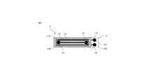
上記の実施形態によるスマートガイドワイヤにおけるガイドワイヤの構成について、図8により説明する。
ガイドワイヤ4は、ワイヤ先端部41、ドライバー部42およびワイヤ連結部からなる。ワイヤ先端部41には、最先端に先端(プラチナ)411、オーステナイト系ステンレスのコアワイヤ412、補強コイル413およびスプリングコイル414からなるステンレス磁石415を構成し、コアワイヤ412の外周部に接触圧および曲げ応力を検知するSI素子31からなる接触圧センサ416が配置されている。The configuration of the guide wire in the smart guide wire according to the above embodiment will be described with reference to FIG.
The guide wire 4 includes a
ドライバー部42には、ハンドル42Hとトルカー42Tとからなる。ハンドル42Hには、ハンドルのトルクを計測するトルクセンサ421、MCU(マイクロコンピュータユニット)422、ハンドルの回転方位および回転速度を計測する電子コンパス423および加速度センサ424からなるモーションセンサを配置されている。The
トルカー42Tには、トルカー42Tの回転量を計測するトルカー回転量計測装置である回転量計測センサ425、トルカー42Tのトルクを計測するトルクセンサ426が配置されている。
ワイヤ先端部41の回転を41R、ハンドル42Hの回転を42HR、トルカー42Tの回転を42TRにて図示する。The torque sensor 42T is provided with a rotation amount measurement sensor 425, which is a torquer rotation amount measuring device for measuring the rotation amount of the torquer 42T, and a torque sensor 426 for measuring the torque of the torquer 42T.
The rotation of the
ガイドワイヤの実施形態から次のことが得られた。
1)ワイヤ先端部41のステンレス磁石315と外部の磁気ベクトルセンサグリッドおよび位置計算データ処理装置を組み合わせて、ガイド先端の位置と方位が求めることができるようになった。
2)ワイヤ先端部の4個の歪ゲージ(SI素子)によって、ワイヤ先端の接触圧力および先端部の曲がり応力、角度、曲がりの向きが測定できるようになった。
3)ドライバー部42のトルカー42Tに取り付けられたトルクセンサ426で、ワイヤの押し込み圧力およびトルカー回転量計測装置425(回転量計測センサ)で、トルカー42Tによるワイヤの送り長さが計測できるようになった。
4)ドライバー部42に取り付けられたトルクセンサ(421、426)、回転方位計(423)、回転速度計(424)によってガイド先端の方位と回転量の操作関係が定量的に把握することができるようになった。The following was obtained from the guide wire embodiment.
1) By combining the stainless magnet 315 of the
2) With four strain gauges (SI elements) at the tip of the wire, the contact pressure at the tip of the wire and the bending stress, angle, and bending direction of the tip can be measured.
3) The torque sensor 426 attached to the torquer 42T of the
4) The operation relationship between the direction of the guide tip and the amount of rotation can be quantitatively grasped by the torque sensor (421, 426), the rotation azimuth meter (423), and the rotation speed meter (424) attached to the
以上、センサ内蔵式のスマートガイドワイヤによって、今まで治療医師の経験と勘に頼っていたガイドワイヤ挿入治療が、手元のドライバーによるガイドワイヤの先端部の移動の定量的関係が把握できるようになり、治療医師は両者の数値関係を見ながら治療ができるようになり、治療が早くより正確に行えるようになると期待される。As described above, the smart guide wire with a built-in sensor makes it possible to grasp the quantitative relationship of the movement of the tip of the guide wire by the driver at hand in the guide wire insertion treatment that has relied on the experience and intuition of the treating doctor. It is expected that the treating doctor will be able to perform treatment while observing the numerical relationship between the two, and that the treatment will be performed faster and more accurately.
本発明の第2の実施形態は、上記のセンサ内蔵式スマートガイドワイヤとガイドワイヤ操作アシストシステムプログラムからなるものである。
スマートガイドワイヤと、X線画像から求めた血管網マップと、 血管網マップ上に治療患部位置を特定するマーキングシステムと、任意の時刻におけるガイドワイヤ先端位置を治療医師に伝達えるシステムと、次の時刻における、つまり所定の時間間隔後における次の目標位置へガイドワイヤ先端を誘導するのに必要なトルクとワイヤ押し込み量と回転角を計算して治療医師に伝達するシステムと、この操作を繰り返して治療医師が最終的にガイドワイヤを治療患部位置まで誘導する治療をアシストするガイドワイヤ操作アシストシステムである。A second embodiment of the present invention comprises the above-mentioned sensor built-in smart guide wire and guide wire operation assist system program.
A smart guide wire, a vascular network map obtained from an X-ray image, a marking system that identifies the position of the affected area on the vascular network map, a system that can transmit the guide wire tip position at any time to the treating doctor, and the following A system that calculates the torque, wire push amount, and rotation angle required to guide the guide wire tip to the next target position at the time, that is, after a predetermined time interval, and transmits it to the treating doctor, and this operation is repeated. It is a guide wire operation assist system that assists the treatment in which the treating doctor finally guides the guide wire to the position of the affected area.
ガイドワイヤ操作アシストシステムプログラムは、ある時刻t(i)におけるガイドワイヤの先端位置に至るまでに時刻t(0)からt(i)までに計測した、血管マップの経路情報とワイヤの先端位置の方位・位置と移動量およびドライバー側のトルク値、ハンドル回転量、トルカーのトルクと回転量とワイヤの送り長さの計測値を総合したデータベースと、次の時刻t(i+1)に誘導すべき先端位置までの方位と位置の微小変化量を計算して治療医師に伝えるプログラムと、X線画像から得た血管の状態から、つまり血管の直径、閉塞度合い、曲がり、距離を考慮して、上記データベースをもとに誘導に必要なドライバーの回転量とトルクおよびトルカーのトルクおよびトルカー回転量を試算して、治療医師に伝えるプログラムと、治療医師はそのデータを参考に経験値と比較しながら治療を行い、これを繰り返して治療実績をデータベース化したプログラムとからなる。
データベースを充実することで、より正確な誘導に必要なトルクとトルカー回転量を治療医師に伝えることができることになると期待される。The guide wire operation assist system program measures the route information of the blood vessel map and the tip position of the wire measured from time t (0) to t (i) before reaching the tip position of the guide wire at a certain time t (i). A database that integrates the measured values of orientation / position and movement amount, driver side torque value, handle rotation amount, torquer torque and rotation amount, and wire feed length, and the tip to be guided to the next time t (i + 1). The above database takes into account the program that calculates the orientation to the position and the amount of minute change in the position and informs the treating doctor, and the state of the blood vessel obtained from the X-ray image, that is, the diameter of the blood vessel, the degree of occlusion, bending, and distance. Based on the program, the driver's rotation amount and torque required for guidance and the torque and torquer rotation amount of the torquer are estimated and transmitted to the treatment doctor, and the treatment doctor refers to the data and compares the treatment with the experience value. It consists of a program that repeats this process and creates a database of treatment results.
It is expected that by enhancing the database, it will be possible to inform the treating doctor of the torque and torquer rotation amount required for more accurate guidance.
本発明の第3の実施形態は、上記センサ内蔵式スマートガイドワイヤとガイドワイヤ操作アシストシステムプログラムをベースにして、ガイドワイヤ操作を自動化、つまりロボット操作にしたものである。
すなわち、上記のガイドワイヤ操作アシストシステムにおいて、ドライバーの操作を治療医師に代えてロボット操作システムにするガイドワイヤ操作ロボットシステムである。In the third embodiment of the present invention, the guide wire operation is automated, that is, the robot operation is performed based on the above-mentioned sensor built-in smart guide wire and guide wire operation assist system program.
That is, in the above-mentioned guide wire operation assist system, it is a guide wire operation robot system in which the operation of the driver is changed to the robot operation system instead of the treating doctor.
ロボット操作は、ガイドワイヤ操作アシストシステムプログラムで得たある任意の時刻t(i)から次の時刻t(i+1)に誘導すべき先端位置までの方位と位置の微小変化量を治療医師に伝え、それを参考に誘導すべき先端位置までの方位と位置の微小移動量を決定し、その値を入力装置で入力して、その入力値が実現できるように、自動的に必要なドライバーの回転量とトルクおよびトルカーのトルクおよびトルカー回転量所定のトルクとトルカー回転量を計算して、ドライバーをコンピュータで操作するロボット操作システムである。The robot operation informs the treating doctor of the orientation and the amount of minute change in the position from an arbitrary time t (i) obtained by the guide wire operation assist system program to the tip position to be guided to the next time t (i + 1). With reference to it, determine the azimuth to the tip position to be guided and the minute movement amount of the position, input the value with the input device, and automatically require the required amount of rotation of the driver so that the input value can be realized. Torque and torque of the torquer and torque of the torquer Rotation amount of the torquer This is a robot operation system that calculates a predetermined torque and the rotation amount of the torquer and operates the driver with a computer.
[実施例1]
ガイドワイヤ4のワイヤ先端部41には磁石415とSI素子316を配置し、ドライバー部42にはトルクセンサ(421、426)、トルカー回転量計測装置(425)、ドライバーの回転角度検出センサ(424)、回転速度検出センサ(425)を配置している。
生体外部に磁気ベクトルセンサグリッド、センサグリッドのデータを使ってワイヤ先端の位置と方位を計算する位置センサデータ処理装置が配置されている。
ワイヤ先端の接触圧と曲げ応力およびドライバー部のトルクと回転量およびドライバーの回転方位と回転速度を計算する応力と回転と回転方位センサデータ処理装置と計算して求めた計測値を表示する装置からなる。[Example 1]
A
A position sensor data processing device that calculates the position and orientation of the wire tip using the magnetic vector sensor grid and the data of the sensor grid is arranged outside the living body.
From the device that displays the measured value calculated by the stress and rotation and rotation direction sensor data processing device that calculates the contact pressure and bending stress of the wire tip, the torque and rotation amount of the driver part, and the rotation direction and rotation speed of the driver. Become.
ワイヤ先端部の磁石は、Ni−Cr系非磁性ステンレスを80%の加工度で強加工して、マルテンサイト相を90%誘起せしめた上で、長手方向に着磁した。オーステナイト系ステンレス鋼のオーステナイト層の安定度の物差しであるMd点はCr量を18.5%、Ni量を8.2%、Mn量を1.0%、Cu量を0.2%、Mo量を0.2%、Si量を0.3%、C量を0.02%、N量を0.02%に調整して、55℃とした。そして、常温にて80%の冷間加工を行なうことで、80%のマルテンサイト量を確保した。The magnet at the tip of the wire was made by strongly processing Ni—Cr-based non-magnetic stainless steel with a processing degree of 80% to induce a martensite phase of 90%, and then magnetizing it in the longitudinal direction. The Md point, which is a measure of the stability of the austenitic layer of austenitic stainless steel, is 18.5% for Cr, 8.2% for Ni, 1.0% for Mn, 0.2% for Cu, and Mo. The amount was adjusted to 0.2%, the amount of Si was 0.3%, the amount of C was 0.02%, and the amount of N was 0.02% to 55 ° C. Then, 80% of the amount of martensite was secured by performing cold working at room temperature of 80%.
ステンレス磁石の保磁力を400Oeであった。磁石形状は直径0.5mm、長さ5mmで、パーミアンス係数は10であった。50Oe程以下の通常の磁界環境においては、減磁する危険はないものとなった。ワイヤの先端のステンレス磁石から発する磁界は、磁石からの距離150mmの位置で0.1mGであった。The coercive force of the stainless magnet was 400 Oe. The magnet shape had a diameter of 0.5 mm and a length of 5 mm, and the permeance coefficient was 10. In a normal magnetic field environment of about 50 Oe or less, there is no danger of demagnetization. The magnetic field generated from the stainless steel magnet at the tip of the wire was 0.1 mG at a distance of 150 mm from the magnet.
磁気ベクトルセンサとしては、センサの検出感度が0.10mGのGSRセンサを用いた。長さ0.4mmのGSR素子を四角錐台形状の3次元素子台座(底辺長さが1.2mm、傾斜角度が30℃、上面の台座の一片の長さ0.3mm)に90度対称に4個貼り付けて、4個の磁気回路に連結して磁気ベクトルセンサとした。As the magnetic vector sensor, a GSR sensor having a detection sensitivity of 0.10 mG was used. A 0.4 mm long GSR element is 90 degrees symmetrical to a quadrangular frustum-shaped three-dimensional element pedestal (base length 1.2 mm, tilt angle 30 ° C, top pedestal piece length 0.3 mm). Four were pasted and connected to four magnetic circuits to form a magnetic vector sensor.
磁気ベクトルセンサグリッドは、このGSRセンサを使った磁気ベクトルセンサを長さ100mm、幅100mmのセンサボード版に、10mm間隔で長さ方向に9行、幅方向に9列のグリッド状に配置した。センサの数は、9×9の81個である。磁気ベクトルセンサ1個は4個の磁気センサを有するので、324個のセンサの測定を一回の測定で行う必要がある。そのためにこのセンサグリッドは、高速切り替えスイッチで測定を走査し、その値をマイクロコンピュータに取り組み、324個のデータを一体化して、50Hzの速度で出力する。
そのセンサグリッドのデータを使ってワイヤ先端の位置と方位を計算する。As the magnetic vector sensor grid, magnetic vector sensors using this GSR sensor were arranged on a sensor board plate having a length of 100 mm and a width of 100 mm in a grid shape of 9 rows in the length direction and 9 columns in the width direction at intervals of 10 mm. The number of sensors is 81, which is 9 × 9. Since one magnetic vector sensor has four magnetic sensors, it is necessary to measure 324 sensors in one measurement. To that end, the sensor grid scans the measurements with a high-speed selector switch, works on the microcomputer with the values, integrates 324 data, and outputs them at a speed of 50 Hz.
The position and orientation of the wire tip are calculated using the data from the sensor grid.
ワイヤ先端部41のコアワイヤ413に取り付けるSI素子1は、幅0.2mm、長さ2mmで歪みゲージファクター1500でフレキシブル基板をもつ超高感度小型の歪みゲージである。SI素子1の構造は、図3に示すようなもので、フレキシブル基板11上に、表面に応力検知体であるアモルファス磁歪ワイヤ13(以下、磁歪ワイヤという。)と磁歪ワイヤに磁歪ワイヤ電極161、162を備えたもので、容易に基板表面を被試験体の表面部に接着剤で固定することができる。
さらに、SI素子1は、歪みと同時に外部磁界の影響を受けるので、磁歪ワイヤ13をパーマロイ11Pで環状に囲い磁気シールドすることにした。パーマロイ11Pは、幅0.05mm、厚みは5μmの薄膜である。
SIセンサの電子回路2としては、図4に示すように、SI素子23(磁歪ワイヤ13)にパルス電流を通電するパルス発振器21と磁歪ワイヤ13に生じる歪み量に対応したインピーダンス変化をワイヤ電圧変化として取り出して、サンプルホールドするサンプルホールド回路26と、ホールド電圧を増幅して出力する増幅回路27とからなっている。励磁周波数は200MHzとした。The
Further, since the
As shown in FIG. 4, as the
上記SI素子1を図5に示すようにワイヤ先端から3mmの位置に、90度対称に4個取り付け、その出力をフレキシブル配線で外部の電子回路に連結し、4個の値(σx1、σx2、σy1、σy2)の平均値を計算し、その値を接触圧として求めた。ここで、電子回路は図6に示すような図3に示した電子回路を4個組み合わせたものを使用した。
またσx=1/2(σx1―σx2)、σy=1/2(σy1―σy2)を先端部の曲げ応力ベクトルσxy=(σx、σy)として求め、ワイヤ先端部の曲がり方向と曲がり強さ(すなわち曲げ角度)を求めることができる。As shown in FIG. 5, four
Further, σx = 1/2 (σx1-σx2) and σy = 1/2 (σy1-σy2) are obtained as the bending stress vector σxy = (σx, σy) at the tip, and the bending direction and bending strength of the wire tip (σx, σy) are obtained. That is, the bending angle) can be obtained.
本発明の被試験体の表面応力を計測するトルクセンサ素子の構造は、図7に示すように、長さ2mm、幅0.2mmで、フレキシブル基板を持つ上記SIセンサ4個を90度対称に配置したものである。被試験体の表面応力を測定するトルクセンサ素子は、フレキシブル基板11上に4個のSI素子(X1、X2、Y1、Y2)が原点(O点)を中心として4回対称に対角線上に配置されて、各々のSI素子が計測する応力(σx1、σx2、σy1、σy2)について、X軸方向の応力であるσx1およびσx2 を加算し、X軸方向と直交するY軸方向の応力であるσy1およびσy2 を加算し、次にX軸方向の加算値とY軸方向の加算値との差分σxyは、σxy=(σx1+σx2)−(σy1+σy2)なる式で算出して、原点(O点)の位置におけるひねり応力の測定を可能とする。As shown in FIG. 7, the structure of the torque sensor element for measuring the surface stress of the test object of the present invention is 2 mm in length and 0.2 mm in width, and the four SI sensors having a flexible substrate are symmetrical by 90 degrees. It is the one that was placed. In the torque sensor element for measuring the surface stress of the test object, four SI elements (X1, X2, Y1, Y2) are arranged diagonally four times symmetrically about the origin (point O) on the flexible substrate 11. Then, for the stresses (σx1, σx2, σy1, σy2) measured by each SI element, the stresses in the X-axis direction σx1 and σx2 are added, and the stress in the Y-axis direction orthogonal to the X-axis direction is σy1. And σy2 are added, and then the difference σxy between the added value in the X-axis direction and the added value in the Y-axis direction is calculated by the formula σxy = (σx1 + σx2)-(σy1 + σy2), and the position of the origin (point O). Allows measurement of torsional stress in.
上記トルクセンサ2個を、ドライバー側のハンドルとトルカーにそれぞれ取り付けて、ハンドル上のトルクセンサでワイヤ先端の回転にかかる力を計測し、トルカーにかかるトルクでワイヤ挿入時に負荷する押し付け力を計測した。トルカーにかかる力は、ハンドルを固定してトルカーを回転させて計測した。ハンドルにかかるトルクは、ハンドルを回転させてガイドワイヤ先端を回転させる時の抵抗力に対応するものである。The two torque sensors were attached to the handle on the driver side and the torque sensor, respectively, and the torque sensor on the handle measured the force applied to the rotation of the wire tip, and the torque applied to the torquer measured the pressing force applied when the wire was inserted. .. The force applied to the torquer was measured by fixing the handle and rotating the torquer. The torque applied to the handle corresponds to the resistance force when the handle is rotated to rotate the tip of the guide wire.
トルカーのトルク強さおよびワイヤの送り量とガイドワイヤ先端の接触圧の三つの値から、先端部における進路を妨害する障害物の様子および誘導血管経路における抵抗力を推定することが可能になった。From the three values of the torque strength of the torquer, the feed amount of the wire, and the contact pressure at the tip of the guide wire, it has become possible to estimate the appearance of obstacles obstructing the course at the tip and the resistance force in the induced vascular path. ..
トルカーの回転量の計測装置については、トルカー側のシャフト表面に磁気スケールメモリを刻み、それをハンドル側に端面に取り付けた磁気センサで回転量を検知する方式のものとした。これによりハンドルとトルカーの相対的な回転量を計測することにより、その回転量からワイヤの送り量を算出することができる。As for the torquer rotation amount measuring device, a magnetic scale memory is engraved on the shaft surface on the torquer side, and the rotation amount is detected by a magnetic sensor attached to the end face on the handle side. As a result, by measuring the relative rotation amount of the handle and the torquer, the wire feed amount can be calculated from the rotation amount.
トルカーのトルク強さおよびワイヤの送り量とワイヤ先端部の接触圧の三つの値から、ワイヤ先端部における進路を妨害する障害物の様子および誘導血管経路における抵抗力を推定することが可能になった。From the three values of the torque strength of the torquer, the feed amount of the wire, and the contact pressure at the tip of the wire, it is possible to estimate the appearance of obstacles obstructing the course at the tip of the wire and the resistance force in the induced vascular path. It was.
ハンドルに電子コンパス(サイズは2mm×2mm×厚み1mm)と3軸加速度センサ(サイズは2mm×2mm×厚み1mm)からなるモーションセンサを取り付けて、ハンドルの回転方位、回転量および回転速度を計測した。ここで、GSRセンサを活用した電子コンパスを採用して、電子コンパスの方位精度を、0.1度とした。A motion sensor consisting of an electronic compass (
ドライバーの回転量、ガイドワイヤの先端部の方位と曲がった状態のワイヤ最先端部の方位およびその変化から、ドライバーの回転操作で、先端部の向きを適切に操作して効率よく進路経路に沿ってガイドワイヤを誘導することができた。Based on the amount of rotation of the driver, the orientation of the tip of the guide wire, the orientation of the tip of the wire in a bent state, and its change, the direction of the tip can be appropriately manipulated by rotating the driver to efficiently follow the course path. I was able to guide the guide wire.
以上のセンサを内蔵したガイドワイヤ4を図8に示す。ワイヤ先端部41のステンレス磁石415と外部の磁気ベクトルセンサグリッドおよび位置計算データ処理装置を組み合わせて、ガイドワイヤ4の先端の位置と方位を求めることができた。
ワイヤ先端部の4個のSI素子416によって、ワイヤ先端の接触圧および先端部の曲がり応力、角度、曲がりの向きが測定できた。
ドライバー部42のトルカー42Tに取り付けられたトルクセンサ426で、ワイヤの押し込み圧力およびトルカー回転量計測装置425で、トルカーによるワイヤの送り長さが計測できた。
ドライバー部42に取り付けられたトルクセンサ(421)、電子コンパス423と3軸加速度センサ424とからなる回転方位計および回転方位計の時間変化から計算で回転速度を求める回転速度計によってガイド先端の方位と回転量の操作関係が定量的に把握することができた。
以上、センサ内蔵式のガイドワイヤによって、今まで治療医師の経験と勘に頼っていたガイドワイヤ挿入治療が、手元のドライバーによるガイドワイヤの先端部の移動の定量的関係が把握できるようになり、治療医師は両者の数値関係を見ながら治療ができるようになり、治療が早くより正確に行えるようになると期待される。The guide wire 4 incorporating the above sensor is shown in FIG. By combining the
With the four
With the torque sensor 426 attached to the torquer 42T of the
The direction of the tip of the guide by the torque sensor (421) attached to the
As described above, the guide wire with a built-in sensor makes it possible to grasp the quantitative relationship of the movement of the tip of the guide wire by the driver at hand in the guide wire insertion treatment, which has relied on the experience and intuition of the treating doctor. It is expected that the treating doctor will be able to perform treatment while observing the numerical relationship between the two, and will be able to perform treatment faster and more accurately.
[実施例2]
上記実施例1に記載したセンサ内蔵式ガイドワイヤとガイドワイヤ操作アシストシステムプログラムからなるものである。
ガイドワイヤ操作アシストシステムプログラムは、ある時刻t(i)におけるガイドワイヤの先端位置に至るまでに時刻t(0)からt(i)までに計測した、血管マップの経路情報とワイヤの先端位置の方位・位置と移動量およびドライバー側のトルク値、ハンドル回転量、トルカーのトルクと回転量とワイヤの送り長さの計測値を総合したデータベース、と 、次の時刻t(i+1)に誘導すべき先端位置までの方位と位置の微小変化量を計算して治療医師に伝えるプログラムと、
X線画像から得た血管の状態から、つまり血管の直径、閉塞度合い、曲がり、距離を考慮して、上記データベースをもとに誘導に必要なドライバーの回転量とトルクおよびトルカーのトルクおよびトルカー回転量を試算して、治療医師に伝えるプログラムと
および治療医師はそのデータを参考に経験値と比較しながら治療を行い、これを繰り返して治療実績をデータベース化したプログラムとからなる。
データベースを充実することで、より正確な誘導に必要なトルクとトルカー回転量を治療医師に伝えることができるようになると期待される。[Example 2]
It comprises the sensor built-in type guide wire and the guide wire operation assist system program described in the first embodiment.
The guide wire operation assist system program measures the route information of the blood vessel map and the tip position of the wire measured from time t (0) to t (i) before reaching the tip position of the guide wire at a certain time t (i). A database that integrates the directional / position and movement amount, torque value on the driver side, handle rotation amount, torque and rotation amount of the torquer, and measured values of the wire feed length, and should be guided to the next time t (i + 1). A program that calculates the direction to the tip position and the amount of minute change in position and informs the treating doctor,
From the state of the blood vessel obtained from the X-ray image, that is, considering the diameter, degree of obstruction, bending, and distance of the blood vessel, the amount and torque of the driver and the torque of the torker and the torker rotation required for guidance based on the above database. It consists of a program that estimates the amount and informs the treating doctor, and a program that the treating doctor performs treatment while comparing it with the experience value with reference to the data, and repeats this to create a database of treatment results.
It is expected that by enhancing the database, it will be possible to inform the treating doctor of the torque and torquer rotation amount required for more accurate guidance.
[実施例3]
上記実施例2をベースに、そのガイドワイヤ操作を自動化、つまりロボット操作にしたものである。
ロボット操作は、ガイドワイヤ操作アシストシステムプログラムで得たある任意の時刻t(i)から次の時刻t(i+1)に誘導すべき先端位置までの方位と位置の微小変化量を治療医師に伝え、それを参考に誘導すべき先端位置までの方位と位置の微小移動量を決定し、その値を入力装置で入力して、その入力値が実現できるように、自動的に必要なドライバーの回転量とトルクおよびトルカーのトルクおよびトルカー回転量所定のトルクとトルカー回転量を計算して、ドライバーをコンピュータで操作するロボット操作システムである。[Example 3]
Based on the above-mentioned second embodiment, the guide wire operation is automated, that is, the robot operation is performed.
The robot operation informs the treating doctor of the orientation and the amount of minute change in the position from an arbitrary time t (i) obtained by the guide wire operation assist system program to the tip position to be guided to the next time t (i + 1). With reference to it, determine the azimuth to the tip position to be guided and the minute movement amount of the position, input the value with the input device, and automatically require the required amount of rotation of the driver so that the input value can be realized. Torque and torque of the torquer and torque of the torquer Rotation amount of the torquer This is a robot operation system that calculates a predetermined torque and the rotation amount of the torquer and operates the driver with a computer.
本発明は、ガイドワイヤにセンサを内蔵してロボット操作を可能にするもので、治療操作を容易にし、かつX線照射時間を少なくすることを可能とする技術として広く普及するものと期待されるである。 The present invention has a sensor built into a guide wire to enable robot operation, and is expected to be widely used as a technique that facilitates treatment operation and reduces X-ray irradiation time. Is.
1:SI素子(応力インピーダンスセンサ素子)
11:フレキシブル基板(基板)、11R:レジスト層、11P:パーマロイ、12:溝、13:磁歪ワイヤ、14:磁歪ワイヤ端子、15:配線、16(161、162):磁歪ワイヤ電極
1A:トルクセンサ素子
10:SI素子(X1、X2、Y1、Y2)、11:フレキシブル基板、12:溝、13:磁歪ワイヤ、141:磁歪ワイヤ出力端子、142:磁歪ワイヤグランド端子、15:配線、160:グランド共通電極、161:出力電極、162:グランド電極、17:リード線(出力電極用)、18:リード線(グランド電極用)
2:電子回路
21:パルス発振器、22:電子スイッチ、23:SI素子、24:高速電子スイッチ、25:コンデンサ、26:サンプルホールド回路、27:増幅器
2A:電子回路
21:パルス発振器、22(22A、22B、22C、22D):電子スイッチ、23(23A、23B、23C、23D):SI素子、24(24A、24B、24C、24D):高速電子スイッチ、25(25A、25B、25C、25D):コンデンサ、26(26A、26B、26C、26D):サンプルホールド回路、27(27A、27B、27C、27D):増幅器、28(28A、28B、28C、28D):電子スイッチ
3:接触圧センサ素子
31:SI素子、311:磁歪ワイヤ、32:コアワイヤ、33:レジンコート
4:ガイドワイヤ
41:ワイヤ先端部、411:先端(プラチナ)、412:コアワイヤ、413:補強コイル、414:スプリングコイル、415:ステンレス磁石、416:接触圧センサ(SI素子)、41R:ワイヤ先端部の回転、42:ドライバー部、42H:ハンドル、42T:トルカー、421:トルクセンサ、422:MCU(マイクロコンピュータユニット)、423:電子コンパス、424:3軸加速度センサ、425:回転量計測センサ(回転量計測装置)、426:トルクセンサ、42HR:ハンドルの回転、42TR:トルカーの回転1: SI element (stress impedance sensor element)
11: Flexible substrate (board), 11R: Resist layer, 11P: Permalloy, 12: Groove, 13: Magnetic strain wire, 14: Magnetic strain wire terminal, 15: Wiring, 16 (161, 162): Magnetic strain wire electrode 1A: Torque sensor Element 10: SI element (X1, X2, Y1, Y2), 11: Flexible substrate, 12: Groove, 13: Magnetic strain wire, 141: Magnetic strain wire output terminal, 142: Magnetic strain wire ground terminal, 15: Wiring, 160: Ground Common electrode, 161: Output electrode, 162: Ground electrode, 17: Lead wire (for output electrode), 18: Lead wire (for ground electrode)
2: Electronic circuit 21: Pulse oscillator, 22: Electronic switch, 23: SI element, 24: High-speed electronic switch, 25: Condenser, 26: Sample hold circuit, 27: Amplifier 2A: Electronic circuit 21: Pulse oscillator, 22 (22A) , 22B, 22C, 22D): Electronic switch, 23 (23A, 23B, 23C, 23D): SI element, 24 (24A, 24B, 24C, 24D): High-speed electronic switch, 25 (25A, 25B, 25C, 25D) : Condenser, 26 (26A, 26B, 26C, 26D): Sample hold circuit, 27 (27A, 27B, 27C, 27D): Amplifier, 28 (28A, 28B, 28C, 28D): Electronic switch 3: Contact pressure sensor element 31: SI element, 311: Magnetic strain wire, 32: Core wire, 33: Resin coat 4: Guide wire 41: Wire tip, 411: Tip (platinum), 412: Core wire, 413: Reinforcing coil, 414: Spring coil, 415 : Stainless magnet, 416: Contact pressure sensor (SI element), 41R: Rotation of wire tip, 42: Driver part, 42H: Handle, 42T: Torker, 421: Torque sensor, 422: MCU (microcomputer unit), 423 : Electronic compass, 424: 3-axis acceleration sensor, 425: Rotation amount measurement sensor (rotation amount measurement device), 426: Torque sensor, 42HR: Handle rotation, 42TR: Torker rotation
Claims (6)
Translated fromJapanese生体外部に磁気ベクトルセンサグリッドと、
前記磁気ベクトルセンサグリッドのデータを使ってワイヤ先端の位置と方位を計算する位置センサデータ処理装置と、
計算して求めた位置と方位の計測値を表示する表示装置とからなることを特徴とするスマートガイドワイヤ。A magnet is provided at the tip of the guide wire.
With a magnetic vector sensor grid outside the living body,
A position sensor data processing device that calculates the position and orientation of the wire tip using the data from the magnetic vector sensor grid, and
A smart guide wire characterized by consisting of a display device that displays the measured values of the calculated position and orientation.
生体外部に磁気ベクトルセンサグリッドと、
前記磁気ベクトルセンサグリッドのデータを使ってワイヤ先端の位置と方位を計算する位置センサデータ処理装置と、
前記ワイヤ先端の接触圧と曲げ応力を計算する応力センサデータ処理装置と、
計算して求めた計測値を表示する表示装置とからなることを特徴とするスマートガイドワイヤ。A magnet and a strain gauge for measuring the stress applied to the wire tip are provided at the wire tip of the guide wire.
With a magnetic vector sensor grid outside the living body,
A position sensor data processing device that calculates the position and orientation of the wire tip using the data from the magnetic vector sensor grid, and
A stress sensor data processing device that calculates the contact pressure and bending stress at the tip of the wire,
A smart guide wire characterized by consisting of a display device that displays the measured values calculated and obtained.
前記ガイドワイヤのドライバー部にハンドルおよびトルカーにかかる応力および回転量を計測するトルクセンサおよびトルカー回転量計測装置を備え、
生体外部に磁気ベクトルセンサグリッドと、
前記磁気ベクトルセンサグリッドのデータを使ってワイヤ先端の位置と方位を計算する位置センサデータ処理装置と、
前記ワイヤ先端の接触圧と曲げ応力およびドライバー部の前記応力と前記回転量を計算する応力センサデータ処理装置と回転センサデータ処理装置と、
計算して求めた計測値を表示する表示装置からなることを特徴とするスマートガイドワイヤ。A magnet and a strain gauge for measuring the stress applied to the wire tip are provided at the wire tip of the guide wire.
The driver portion of the guide wire is provided with a torque sensor for measuring stress and rotation amount applied to the handle and the torquer, and a torquer rotation amount measuring device.
With a magnetic vector sensor grid outside the living body,
A position sensor data processing device that calculates the position and orientation of the wire tip using the data from the magnetic vector sensor grid, and
A stress sensor data processing device and a rotation sensor data processing device for calculating the contact pressure and bending stress of the wire tip, the stress of the driver portion, and the rotation amount,
A smart guide wire characterized by consisting of a display device that displays the measured values calculated and obtained.
前記ガイドワイヤのドライバー部にハンドルおよびトルカーにかかる応力および回転量を計測するトルクセンサおよびトルカー回転量計測装置を備え、
前記ガイドワイヤのドライバー部のハンドル部に回転角度検出センサおよび回転速度検出センサを備え、
生体外部に磁気ベクトルセンサグリッドと、前記磁気センサグリッドのデータを使ってワイヤ先端の位置と方位を計算する位置センサデータ処理装置と、
ワイヤ先端の接触圧と曲げ応力、およびドライバーのトルク、回転量、回転方位、回転速度を計算する応力センサデータ処理装置と回転センサデータ処理装置と、
計算して求めた計測値を表示する表示装置からなることを特徴とするスマートガイドワイヤ。A magnet and a strain gauge for measuring the stress applied to the wire tip are provided at the wire tip of the guide wire.
The driver portion of the guide wire is provided with a torque sensor for measuring stress and rotation amount applied to the handle and the torquer, and a torquer rotation amount measuring device.
A rotation angle detection sensor and a rotation speed detection sensor are provided on the handle of the driver portion of the guide wire.
A magnetic vector sensor grid outside the living body, a position sensor data processing device that calculates the position and orientation of the wire tip using the data of the magnetic sensor grid, and
Stress sensor data processing device and rotation sensor data processing device that calculate the contact pressure and bending stress of the wire tip, and driver torque, rotation amount, rotation direction, and rotation speed,
A smart guide wire characterized by consisting of a display device that displays the measured values calculated and obtained.
X線画像から求めた血管網マップと、
血管網マップ上に治療患部位置を特定するマーキングシステムと、
任意の時刻におけるガイドワイヤ先端位置を治療医師に伝達するシステムと、
次の時刻における、つまり所定の時間間隔後における次の目標位置へガイドワイヤ先端を誘導するのに必要なトルクとワイヤ押し込み量と回転角を計算して治療医師に伝達するシステムと、
この操作を繰り返して治療医師が最終的にガイドワイヤを治療患部位置まで誘導する治療をアシストすることを特徴とするガイドワイヤ操作アシストシステム。The smart guide wire according to claim 4 and
The vascular network map obtained from the X-ray image and
A marking system that identifies the location of the affected area on the vascular network map,
A system that transmits the tip position of the guide wire to the treating doctor at any time,
A system that calculates the torque, wire push amount, and angle of rotation required to guide the guide wire tip to the next target position at the next time, that is, after a predetermined time interval, and transmits it to the treating doctor.
A guide wire operation assist system characterized in that the treatment doctor assists the treatment in which the guide wire is finally guided to the position of the affected area by repeating this operation.
ドライバーの操作を治療医師に代えてロボット操作システムにすることを特徴とするガイドワイヤ操作ロボットシステム。
In the guide wire operation assist system according to claim 5.
A guide wire operation robot system characterized in that the operation of the driver is changed to a robot operation system instead of the treating doctor.
Priority Applications (1)
| Application Number | Priority Date | Filing Date | Title |
|---|---|---|---|
| JP2019206595AJP2021081223A (en) | 2019-11-15 | 2019-11-15 | Smart guide wire and guide wire operation system |
Applications Claiming Priority (1)
| Application Number | Priority Date | Filing Date | Title |
|---|---|---|---|
| JP2019206595AJP2021081223A (en) | 2019-11-15 | 2019-11-15 | Smart guide wire and guide wire operation system |
Publications (1)
| Publication Number | Publication Date |
|---|---|
| JP2021081223Atrue JP2021081223A (en) | 2021-05-27 |
Family
ID=75964793
Family Applications (1)
| Application Number | Title | Priority Date | Filing Date |
|---|---|---|---|
| JP2019206595AWithdrawnJP2021081223A (en) | 2019-11-15 | 2019-11-15 | Smart guide wire and guide wire operation system |
Country Status (1)
| Country | Link |
|---|---|
| JP (1) | JP2021081223A (en) |
Cited By (3)
| Publication number | Priority date | Publication date | Assignee | Title |
|---|---|---|---|---|
| JP7173506B1 (en) | 2022-03-01 | 2022-11-16 | マグネデザイン株式会社 | Method for manufacturing Cr-Ni stainless steel magnet for guide wire, smart guide wire, guide wire manipulating system, and guide wire manipulating robot system |
| WO2022244183A1 (en)* | 2021-05-20 | 2022-11-24 | 朝日インテック株式会社 | Medical system and navigation method |
| CN115540947A (en)* | 2022-10-20 | 2022-12-30 | 微亚医疗科技(苏州)有限公司 | Device for detecting guidewire delivery speed and guidewire delivery resistance |
Citations (5)
| Publication number | Priority date | Publication date | Assignee | Title |
|---|---|---|---|---|
| JPH11178932A (en)* | 1997-12-18 | 1999-07-06 | Terumo Corp | Device for inserting into organism |
| JP2012513845A (en)* | 2008-12-31 | 2012-06-21 | セント・ジュード・メディカル・エイトリアル・フィブリレーション・ディヴィジョン・インコーポレーテッド | Robot catheter system input device |
| JP2018511353A (en)* | 2015-01-22 | 2018-04-26 | コーニンクレッカ フィリップス エヌ ヴェKoninklijke Philips N.V. | Device visualization by optical shape sensing of guide wires |
| JP2019521742A (en)* | 2016-06-01 | 2019-08-08 | ベクトン・ディキンソン・アンド・カンパニーBecton, Dickinson And Company | Medical devices, systems, and methods utilizing permanent magnets and magnetizable features |
| JP2019188124A (en)* | 2018-02-22 | 2019-10-31 | キヤノン ユーエスエイ, インコーポレイテッドCanon U.S.A., Inc | Torque control device, method and system |
- 2019
- 2019-11-15JPJP2019206595Apatent/JP2021081223A/ennot_activeWithdrawn
Patent Citations (5)
| Publication number | Priority date | Publication date | Assignee | Title |
|---|---|---|---|---|
| JPH11178932A (en)* | 1997-12-18 | 1999-07-06 | Terumo Corp | Device for inserting into organism |
| JP2012513845A (en)* | 2008-12-31 | 2012-06-21 | セント・ジュード・メディカル・エイトリアル・フィブリレーション・ディヴィジョン・インコーポレーテッド | Robot catheter system input device |
| JP2018511353A (en)* | 2015-01-22 | 2018-04-26 | コーニンクレッカ フィリップス エヌ ヴェKoninklijke Philips N.V. | Device visualization by optical shape sensing of guide wires |
| JP2019521742A (en)* | 2016-06-01 | 2019-08-08 | ベクトン・ディキンソン・アンド・カンパニーBecton, Dickinson And Company | Medical devices, systems, and methods utilizing permanent magnets and magnetizable features |
| JP2019188124A (en)* | 2018-02-22 | 2019-10-31 | キヤノン ユーエスエイ, インコーポレイテッドCanon U.S.A., Inc | Torque control device, method and system |
Cited By (5)
| Publication number | Priority date | Publication date | Assignee | Title |
|---|---|---|---|---|
| WO2022244183A1 (en)* | 2021-05-20 | 2022-11-24 | 朝日インテック株式会社 | Medical system and navigation method |
| JP7173506B1 (en) | 2022-03-01 | 2022-11-16 | マグネデザイン株式会社 | Method for manufacturing Cr-Ni stainless steel magnet for guide wire, smart guide wire, guide wire manipulating system, and guide wire manipulating robot system |
| WO2023167051A1 (en)* | 2022-03-01 | 2023-09-07 | マグネデザイン株式会社 | METHOD FOR PRODUCING Cr-Ni-BASED STAINLESS MAGNET FOR GUIDE WIRES, SMART GUIDE WIRE, GUIDE WIRE OPERATION SYSTEM, AND GUIDE WIRE OPERATION ROBOT SYSTEM |
| JP2023127017A (en)* | 2022-03-01 | 2023-09-13 | マグネデザイン株式会社 | MANUFACTURING METHOD OF Cr-Ni STAINLESS STEEL MAGNET FOR GUIDE WIRE, SMART GUIDE WIRE, GUIDE WIRE MANIPULATION SYSTEM AND GUIDE WIRE MANIPULATION ROBOT SYSTEM |
| CN115540947A (en)* | 2022-10-20 | 2022-12-30 | 微亚医疗科技(苏州)有限公司 | Device for detecting guidewire delivery speed and guidewire delivery resistance |
Similar Documents
| Publication | Publication Date | Title |
|---|---|---|
| US6522907B1 (en) | Surgical navigation | |
| Hu et al. | A cubic 3-axis magnetic sensor array for wirelessly tracking magnet position and orientation | |
| US11998306B2 (en) | Probe for determining magnetic marker locations | |
| JP5570691B2 (en) | Method and apparatus for guiding a locking screw distally into an intramedullary nail | |
| US6757557B1 (en) | Position location system | |
| EP0655138B1 (en) | Position location system | |
| US8249689B2 (en) | Coil arrangement for electromagnetic tracking method and system | |
| US7834621B2 (en) | Electromagnetic tracking employing scalar-magnetometer | |
| US8131342B2 (en) | Method and system for field mapping using integral methodology | |
| US7573258B2 (en) | Coil arrangement for electromagnetic tracker method and system | |
| JP2021081223A (en) | Smart guide wire and guide wire operation system | |
| JP2024161066A (en) | Magnetic field probe to determine placement of implanted magnetic markers | |
| JP7173506B1 (en) | Method for manufacturing Cr-Ni stainless steel magnet for guide wire, smart guide wire, guide wire manipulating system, and guide wire manipulating robot system | |
| CN101361660A (en) | A positioning method and positioning system for multiple magnetic targets | |
| Totsu et al. | Three-axis magneto-impedance effect sensor system for detecting position and orientation of catheter tip | |
| CN110870790A (en) | Single Axis Sensor (SAS) with Hall Sensor Using External Magnet | |
| CA2358682A1 (en) | Position location system | |
| US20210100621A1 (en) | Surgical Navigation System For Registering Coordinates of Patient-Customized Tool | |
| CA2288411C (en) | Position location system | |
| Zeng et al. | An analytic algorithm based position and orientation detection using a tri-axial magnetoresistive sensor | |
| US10076267B2 (en) | Methods and systems for improved navigation | |
| Park et al. | Technical Review: Electromagnetic Sensor System for Localization of Medical Devices | |
| CN117481809A (en) | Magnetic navigation system for operation | |
| JP2009000409A (en) | Magnetic resonance therapy equipment |
Legal Events
| Date | Code | Title | Description |
|---|---|---|---|
| A711 | Notification of change in applicant | Free format text:JAPANESE INTERMEDIATE CODE: A711 Effective date:20210816 | |
| A621 | Written request for application examination | Free format text:JAPANESE INTERMEDIATE CODE: A621 Effective date:20211112 | |
| A871 | Explanation of circumstances concerning accelerated examination | Free format text:JAPANESE INTERMEDIATE CODE: A871 Effective date:20211112 | |
| A521 | Request for written amendment filed | Free format text:JAPANESE INTERMEDIATE CODE: A523 Effective date:20211022 | |
| A131 | Notification of reasons for refusal | Free format text:JAPANESE INTERMEDIATE CODE: A131 Effective date:20211221 | |
| A761 | Written withdrawal of application | Free format text:JAPANESE INTERMEDIATE CODE: A761 Effective date:20220128 |