JP2021076799A - Image capturing lens - Google Patents
Image capturing lensDownload PDFInfo
- Publication number
- JP2021076799A JP2021076799AJP2019205378AJP2019205378AJP2021076799AJP 2021076799 AJP2021076799 AJP 2021076799AJP 2019205378 AJP2019205378 AJP 2019205378AJP 2019205378 AJP2019205378 AJP 2019205378AJP 2021076799 AJP2021076799 AJP 2021076799A
- Authority
- JP
- Japan
- Prior art keywords
- lens
- optical axis
- image
- curvature
- image pickup
- Prior art date
- Legal status (The legal status is an assumption and is not a legal conclusion. Google has not performed a legal analysis and makes no representation as to the accuracy of the status listed.)
- Granted
Links
- 230000003287optical effectEffects0.000claimsabstractdescription81
- 230000014509gene expressionEffects0.000claimsabstractdescription73
- 238000003384imaging methodMethods0.000claimsdescription27
- 201000009310astigmatismDiseases0.000description46
- 230000004075alterationEffects0.000description44
- 206010010071ComaDiseases0.000description17
- 238000012937correctionMethods0.000description16
- 230000005499meniscusEffects0.000description7
- 238000004519manufacturing processMethods0.000description4
- 239000000463materialSubstances0.000description4
- 238000010586diagramMethods0.000description3
- 230000000694effectsEffects0.000description3
- 239000006059cover glassSubstances0.000description2
- 238000005728strengtheningMethods0.000description2
- 230000004304visual acuityEffects0.000description2
- 238000012356Product developmentMethods0.000description1
- 239000011521glassSubstances0.000description1
- 230000002093peripheral effectEffects0.000description1
Images


Classifications
- G—PHYSICS
- G02—OPTICS
- G02B—OPTICAL ELEMENTS, SYSTEMS OR APPARATUS
- G02B13/00—Optical objectives specially designed for the purposes specified below
- G02B13/001—Miniaturised objectives for electronic devices, e.g. portable telephones, webcams, PDAs, small digital cameras
- G02B13/0015—Miniaturised objectives for electronic devices, e.g. portable telephones, webcams, PDAs, small digital cameras characterised by the lens design
- G02B13/002—Miniaturised objectives for electronic devices, e.g. portable telephones, webcams, PDAs, small digital cameras characterised by the lens design having at least one aspherical surface
- G02B13/0045—Miniaturised objectives for electronic devices, e.g. portable telephones, webcams, PDAs, small digital cameras characterised by the lens design having at least one aspherical surface having five or more lenses
- G—PHYSICS
- G02—OPTICS
- G02B—OPTICAL ELEMENTS, SYSTEMS OR APPARATUS
- G02B13/00—Optical objectives specially designed for the purposes specified below
- G02B13/06—Panoramic objectives; So-called "sky lenses" including panoramic objectives having reflecting surfaces
- G—PHYSICS
- G02—OPTICS
- G02B—OPTICAL ELEMENTS, SYSTEMS OR APPARATUS
- G02B13/00—Optical objectives specially designed for the purposes specified below
- G02B13/18—Optical objectives specially designed for the purposes specified below with lenses having one or more non-spherical faces, e.g. for reducing geometrical aberration
- G—PHYSICS
- G02—OPTICS
- G02B—OPTICAL ELEMENTS, SYSTEMS OR APPARATUS
- G02B27/00—Optical systems or apparatus not provided for by any of the groups G02B1/00 - G02B26/00, G02B30/00
- G02B27/0025—Optical systems or apparatus not provided for by any of the groups G02B1/00 - G02B26/00, G02B30/00 for optical correction, e.g. distorsion, aberration
- G—PHYSICS
- G02—OPTICS
- G02B—OPTICAL ELEMENTS, SYSTEMS OR APPARATUS
- G02B9/00—Optical objectives characterised both by the number of the components and their arrangements according to their sign, i.e. + or -
- G02B9/62—Optical objectives characterised both by the number of the components and their arrangements according to their sign, i.e. + or - having six components only
Landscapes
- Physics & Mathematics (AREA)
- General Physics & Mathematics (AREA)
- Optics & Photonics (AREA)
- Lenses (AREA)
Abstract
Description
Translated fromJapanese本発明は、撮像装置に使用されるCCDセンサやC-MOSセンサの固体撮像素子上に被写体の像を結像させる撮像レンズに関するものである。 The present invention relates to an image pickup lens that forms an image of a subject on a solid-state image sensor of a CCD sensor or a C-MOS sensor used in an image pickup apparatus.
近年、家電製品や情報端末機器、自動車等、様々な製品にカメラ機能が搭載されるようになった。今後も、カメラ機能を融合させた様々な商品開発が進んでいくものと考えられる。 In recent years, various products such as home appliances, information terminal devices, and automobiles have come to be equipped with a camera function. It is expected that various product developments that integrate camera functions will continue in the future.
このような機器に搭載される撮像レンズは、小型でありながらも高い解像性能が求められる。 The image pickup lens mounted on such a device is required to have high resolution performance while being small in size.
従来の高性能化を目指した撮像レンズとしては、例えば、以下の特許文献1のような撮像レンズが知られている。 As a conventional image pickup lens aiming at high performance, for example, an image pickup lens as described in Patent Document 1 below is known.
特許文献1には、物体側から順に、負の屈折力を有し、物体側に凹面を向けたメニスカス形状である第1レンズと、正の屈折力を有する第2レンズと、負の屈折力を有する第3レンズ、正の屈折力を有し、物体側に凹面を向けたメニスカス形状である第4レンズと、第5レンズと、像側に凹面を向け、像側の面が少なくとも1つの変曲点を有する非球面形状である第6レンズと、から構成される実質的に6個のレンズからなり、全系の焦点距離と第6レンズの像側の面の近軸曲率半径の関係が、一定の条件を満たすよう構成された撮像レンズが開示されている。 Patent Document 1 describes, in order from the object side, a first lens having a negative refractive power and having a meniscus shape with a concave surface facing the object side, a second lens having a positive refractive power, and a negative refractive power. A third lens having a positive refractive power, a fourth lens having a meniscus shape with a concave surface facing the object side, a fifth lens, and at least one surface facing the image side and having a concave surface facing the image side. It consists of a sixth lens, which has an aspherical shape with a turning point, and substantially six lenses, and the relationship between the focal distance of the entire system and the near-axis radius of curvature of the image-side surface of the sixth lens. However, an imaging lens configured to satisfy certain conditions is disclosed.
特許文献1に記載のレンズ構成で、広角化、および低Fナンバー化を図ろうとした場合、周辺部における収差補正が非常に困難であり、良好な光学性能を得ることはできない。 When trying to widen the angle and reduce the F-number with the lens configuration described in Patent Document 1, it is very difficult to correct aberrations in the peripheral portion, and good optical performance cannot be obtained.
本発明は、上述した課題に鑑みてなされたものであり、広角化、および低Fナンバー化の要求をバランスよく満足しながらも、諸収差が良好に補正された高い解像力を備える撮像レンズを提供することを目的とする。 The present invention has been made in view of the above-mentioned problems, and provides an image pickup lens having a high resolving power in which various aberrations are satisfactorily corrected while satisfying the demands for wide-angle and low F-number in a well-balanced manner. The purpose is to do.
また、本発明において使用する用語に関し、レンズの面の凸面、凹面、平面とは光軸近傍(近軸)における形状を指すものと定義する。屈折力とは、光軸近傍(近軸)における屈折力を指すものと定義する。極点とは接平面が光軸と垂直に交わる光軸上以外における非球面上の点として定義する。光学全長とは、最も物体側に位置する光学素子の物体側の面から撮像面までの光軸上の距離として定義する。なお、光学全長やバックフォーカスは、撮像レンズと撮像面の間に配置されるIRカットフィルタやカバーガラス等の厚みを空気換算して得られる距離とする。 Further, with respect to the terms used in the present invention, the convex surface, the concave surface, and the flat surface of the lens surface are defined to refer to the shapes in the vicinity of the optical axis (paraxial axis). The refractive power is defined as referring to the refractive power near the optical axis (paraxial). A pole is defined as a point on an aspherical surface other than on the optical axis where the tangent plane intersects the optical axis perpendicularly. The total optical length is defined as the distance on the optical axis from the surface of the optical element located closest to the object on the object side to the imaging surface. The total optical length and back focus are distances obtained by converting the thickness of the IR cut filter, cover glass, etc. arranged between the imaging lens and the imaging surface into air.
本発明による撮像レンズは、物体側から像側に向かって順に配置された、光軸近傍で負の屈折力を有する第1レンズと、光軸近傍で物体側に凸面を向けた正の屈折力を有する第2レンズと、光軸近傍で正の屈折力を有する第3レンズと、第4レンズと、光軸近傍で物体側に凹面を向けた第5レンズと、光軸近傍で像側に凹面を向けた第6レンズとから構成される。 The imaging lens according to the present invention includes a first lens having a negative refractive force near the optical axis, which is arranged in order from the object side toward the image side, and a positive refractive force with a convex surface directed toward the object side near the optical axis. A second lens having a positive refractive force near the optical axis, a fourth lens, a fifth lens having a concave surface facing the object side near the optical axis, and an image side near the optical axis. It is composed of a sixth lens with a concave surface facing.
第1レンズは、屈折力を強めることで、広角化を図る。 The first lens aims to widen the angle by strengthening the refractive power.
第2レンズは、低背化を図るとともに、コマ収差、非点収差、歪曲収差を良好に補正する。また、光軸近傍で物体側に凸面を向けることにより、コマ収差、非点収差のより良好な補正が可能になる。 The second lens satisfactorily corrects coma, astigmatism, and distortion while reducing the height. Further, by directing the convex surface toward the object near the optical axis, better correction of coma aberration and astigmatism becomes possible.
第3レンズは、低背化を図るとともに、球面収差、コマ収差、像面湾曲、歪曲収差を良好に補正する。 The third lens satisfactorily corrects spherical aberration, coma, curvature of field, and distortion while reducing the height.
第4レンズは、非点収差、像面湾曲、歪曲収差を良好に補正する。 The fourth lens satisfactorily corrects astigmatism, curvature of field, and distortion.
第5レンズは、コマ収差、非点収差、歪曲収差を良好に補正する。また、光軸近傍で物体側に凹面を向けることにより、非点収差、歪曲収差のより良好な補正が可能になる。 The fifth lens satisfactorily corrects coma, astigmatism, and distortion. Further, by directing the concave surface toward the object near the optical axis, better correction of astigmatism and distortion becomes possible.
第6レンズは、非点収差、像面湾曲、歪曲収差を良好に補正する。また、光軸近傍で像側に凹面を向けることにより、低背化を維持しながらバックフォーカスを確保する。 The sixth lens satisfactorily corrects astigmatism, curvature of field, and distortion. In addition, by directing the concave surface toward the image side near the optical axis, the back focus is secured while maintaining the low profile.
また、上記構成の撮像レンズにおいては、第1レンズの像側の面は、光軸近傍で像側に凹面を向けた形状とすることが望ましい。 Further, in the image pickup lens having the above configuration, it is desirable that the image side surface of the first lens has a shape in which the concave surface faces the image side in the vicinity of the optical axis.
第1レンズの像側の面を光軸近傍で像側に凹面とすることで、非点収差、歪曲収差の良好な補正が可能になる。 By making the surface of the first lens on the image side a concave surface on the image side near the optical axis, it is possible to satisfactorily correct astigmatism and distortion.
また、上記構成の撮像レンズにおいては、第3レンズの像側の面は、光軸近傍で像側に凸面を向けた形状とすることが望ましい。 Further, in the image pickup lens having the above configuration, it is desirable that the image side surface of the third lens has a shape in which the convex surface faces the image side in the vicinity of the optical axis.
第3レンズの像側の面を光軸近傍で像側に凸面とすることで、コマ収差、像面湾曲、歪曲収差の良好な補正が可能になる。 By making the surface of the third lens on the image side convex toward the image near the optical axis, it is possible to satisfactorily correct coma, curvature of field, and distortion.
また、上記構成の撮像レンズにおいては、第6レンズの物体側の面は、光軸近傍で物体側に凸面を向けた形状とすることが望ましい。 Further, in the image pickup lens having the above configuration, it is desirable that the surface of the sixth lens on the object side has a shape in which the convex surface faces the object side in the vicinity of the optical axis.
第6レンズの物体側の面を光軸近傍で物体側に凸面とすることで、非点収差、像面湾曲、歪曲収差の良好な補正が可能になる。 By making the surface of the sixth lens on the object side convex toward the object near the optical axis, it is possible to satisfactorily correct astigmatism, curvature of field, and distortion.
また、上記構成の撮像レンズにおいては、第6レンズの物体側の面は、光軸上以外の位置に極点を有する非球面が形成されていることが望ましい。 Further, in the image pickup lens having the above configuration, it is desirable that the surface of the sixth lens on the object side is formed with an aspherical surface having a pole point at a position other than the optical axis.
第6レンズの物体側の面に、光軸上以外の位置に極点を有する非球面形状を形成することにより、像面湾曲、歪曲収差の良好な補正が可能になる。 By forming an aspherical shape having poles at positions other than on the optical axis on the surface of the sixth lens on the object side, it is possible to satisfactorily correct curvature of field and distortion.
また、上記構成の撮像レンズにおいては、第6レンズの像側の面は、光軸上以外の位置に極点を有する非球面が形成されていることが望ましい。 Further, in the image pickup lens having the above configuration, it is desirable that the surface of the sixth lens on the image side is formed with an aspherical surface having a pole point at a position other than the optical axis.
第6レンズの像側の面に、光軸上以外の位置に極点を有する非球面形状を形成することにより、像面湾曲、歪曲収差の良好な補正が可能になる。 By forming an aspherical shape having poles at positions other than on the optical axis on the image-side surface of the sixth lens, it is possible to satisfactorily correct curvature of field and distortion.
また、上記構成の撮像レンズにおいては、以下の条件式(1)を満足することが望ましい。
(1)0.20<νd2/νd6<0.60
ただし、νd2は第2レンズのd線に対するアッべ数、νd6は第6レンズのd線に対するアッべ数である。Further, it is desirable that the following conditional expression (1) is satisfied in the image pickup lens having the above configuration.
(1) 0.20 <νd2 / νd6 <0.60
However, νd2 is the number of abbreviations for the d-line of the second lens, and νd6 is the number of abbreviations for the d-line of the sixth lens.
条件式(1)は、第2レンズのd線に対するアッベ数、および第6レンズのd線に対するアッベ数の関係を適切な範囲に規定するものである。条件式(1)を満足することで、色収差の良好な補正が可能になる。 The conditional expression (1) defines the relationship between the Abbe number of the second lens with respect to the d-line and the Abbe number of the sixth lens with respect to the d-line within an appropriate range. By satisfying the conditional expression (1), good correction of chromatic aberration becomes possible.
また、上記構成の撮像レンズにおいては、以下の条件式(2)を満足することが望ましい。
(2)12.50<|f6|/D6<90.00
ただし、f6は第6レンズの焦点距離、D6は第6レンズの光軸上の厚みである。Further, it is desirable that the image pickup lens having the above configuration satisfies the following conditional expression (2).
(2) 12.50 << | f6 | / D6 <90.00
However, f6 is the focal length of the sixth lens, and D6 is the thickness on the optical axis of the sixth lens.
条件式(2)は、第6レンズの焦点距離、および第6レンズの光軸上の厚みの関係を適切な範囲に規定するものである。条件式(2)の範囲を満足することで、低背化を図るとともに、非点収差、像面湾曲、歪曲収差の良好な補正が可能になる。 Conditional expression (2) defines the relationship between the focal length of the sixth lens and the thickness of the sixth lens on the optical axis within an appropriate range. By satisfying the range of the conditional expression (2), it is possible to reduce the height and to make good corrections for astigmatism, curvature of field, and distortion.
また、上記構成の撮像レンズにおいては、以下の条件式(3)を満足することが望ましい。
(3)2.50<r12/r2/D6<7.00
ただし、r12は第6レンズの像側の面の近軸曲率半径、r2は第1レンズの像側の面の近軸曲率半径、D6は第6レンズの光軸上の厚みである。Further, it is desirable that the image pickup lens having the above configuration satisfies the following conditional expression (3).
(3) 2.50 <r12 / r2 / D6 <7.00
However, r12 is the paraxial radius of curvature of the surface of the sixth lens on the image side, r2 is the paraxial radius of curvature of the surface of the first lens on the image side, and D6 is the thickness on the optical axis of the sixth lens.
条件式(3)は、第6レンズの像側の面の近軸曲率半径、第1レンズの像側の面の近軸曲率半径、および第6レンズの光軸上の厚みの関係を適切な範囲に規定するものである。条件式(3)の範囲を満足することで、非点収差、像面湾曲、歪曲収差の良好な補正が可能になる。 Conditional expression (3) appropriately relates to the relationship between the paraxial radius of curvature of the image-side surface of the sixth lens, the paraxial radius of curvature of the image-side surface of the first lens, and the thickness of the sixth lens on the optical axis. It is defined in the range. Satisfying the range of the conditional expression (3) enables good correction of astigmatism, curvature of field, and distortion.
また、上記構成の撮像レンズにおいては、以下の条件式(4)を満足することが望ましい。
(4)5.25<|f6|/f<50.00
ただし、f6は第6レンズの焦点距離、fは撮像レンズ全系の焦点距離である。Further, it is desirable that the following conditional expression (4) is satisfied in the image pickup lens having the above configuration.
(4) 5.25 << | f6 | / f <50.00
However, f6 is the focal length of the sixth lens, and f is the focal length of the entire imaging lens system.
条件式(4)は、第6レンズの焦点距離を適切な範囲に規定するものである。条件式(4)の範囲を満足することで、第6レンズの屈折力が適切なものとなり、非点収差、像面湾曲、歪曲収差の良好な補正が可能になる。 The conditional expression (4) defines the focal length of the sixth lens in an appropriate range. By satisfying the range of the conditional expression (4), the refractive power of the sixth lens becomes appropriate, and astigmatism, curvature of field, and distortion can be satisfactorily corrected.
また、上記構成の撮像レンズにおいては、以下の条件式(5)を満足することが望ましい。
(5)−45.00<|f6|/f1<−5.00
ただし、f6は第6レンズの焦点距離、f1は第1レンズの焦点距離である。Further, it is desirable that the following conditional expression (5) is satisfied in the image pickup lens having the above configuration.
(5) -45.00 << | f6 | / f1 <-5.00
However, f6 is the focal length of the sixth lens, and f1 is the focal length of the first lens.
条件式(5)は、第6レンズの焦点距離、および第1レンズの焦点距離の関係を適切な範囲に規定するものである。条件式(5)の範囲を満足することで、第6レンズの屈折力、および第1レンズの屈折力を適切にバランスさせることが可能になる。その結果、広角化を図るとともに、色収差、球面収差、非点収差、像面湾曲、歪曲収差の良好な補正が可能になる。 The conditional expression (5) defines the relationship between the focal length of the sixth lens and the focal length of the first lens in an appropriate range. By satisfying the range of the conditional expression (5), the refractive power of the sixth lens and the refractive power of the first lens can be appropriately balanced. As a result, it is possible to widen the angle and to correct chromatic aberration, spherical aberration, astigmatism, curvature of field, and distortion.
また、上記構成の撮像レンズにおいては、以下の条件式(6)を満足することが望ましい。
(6)−0.95<r2/r6<−0.40
ただし、r2は第1レンズの像側の面の近軸曲率半径、r6は第3レンズの像側の面の近軸曲率半径である。Further, it is desirable that the following conditional expression (6) is satisfied in the image pickup lens having the above configuration.
(6) -0.95 <r2 / r6 <-0.40
However, r2 is the paraxial radius of curvature of the surface of the first lens on the image side, and r6 is the paraxial radius of curvature of the surface of the third lens on the image side.
条件式(6)は、第1レンズの像側の面の近軸曲率半径、および第3レンズの像側の面の近軸曲率半径の関係を適切な範囲に規定するものである。条件式(6)の範囲を満足することで、コマ収差、非点収差、像面湾曲、歪曲収差の良好な補正が可能になる。 Conditional expression (6) defines the relationship between the paraxial radius of curvature of the image-side surface of the first lens and the paraxial radius of curvature of the image-side surface of the third lens in an appropriate range. By satisfying the range of the conditional expression (6), it is possible to satisfactorily correct coma, astigmatism, curvature of field, and distortion.
また、上記構成の撮像レンズにおいては、以下の条件式(7)を満足することが望ましい。
(7)−1.00<r6/r12<−0.25
ただし、r6は第3レンズの像側の面の近軸曲率半径、r12は第6レンズの像側の面の近軸曲率半径である。Further, it is desirable that the following conditional expression (7) is satisfied in the image pickup lens having the above configuration.
(7) -1.00 <r6 / r12 <-0.25
However, r6 is the paraxial radius of curvature of the surface of the third lens on the image side, and r12 is the paraxial radius of curvature of the surface of the sixth lens on the image side.
条件式(7)は、第3レンズの像側の面の近軸曲率半径、および第6レンズの像側の面の近軸曲率半径の関係を適切な範囲に規定するものである。条件式(7)の範囲を満足することで、コマ収差、非点収差、像面湾曲、歪曲収差の良好な補正が可能になる。 Conditional expression (7) defines the relationship between the paraxial radius of curvature of the image-side surface of the third lens and the paraxial radius of curvature of the image-side surface of the sixth lens within an appropriate range. By satisfying the range of the conditional expression (7), it is possible to satisfactorily correct coma, astigmatism, curvature of field, and distortion.
また、上記構成の撮像レンズにおいては、以下の条件式(8)を満足することが望ましい。
(8)0.75<r12/f<2.00
ただし、r12は第6レンズの像側の面の近軸曲率半径、fは撮像レンズ全系の焦点距離である。Further, it is desirable that the following conditional expression (8) is satisfied in the image pickup lens having the above configuration.
(8) 0.75 <r12 / f <2.00
However, r12 is the paraxial radius of curvature of the surface of the sixth lens on the image side, and f is the focal length of the entire imaging lens system.
条件式(8)は、第6レンズの像側の面の近軸曲率半径を適切な範囲に規定するものである。条件式(8)の範囲を満足することで、非点収差、像面湾曲、歪曲収差の良好な補正が可能になる。 Conditional expression (8) defines the paraxial radius of curvature of the image-side surface of the sixth lens in an appropriate range. By satisfying the range of the conditional expression (8), astigmatism, curvature of field, and distortion can be satisfactorily corrected.
また、上記構成の撮像レンズにおいては、以下の条件式(9)を満足することが望ましい。
(9)0.20<T4/T5<1.70
ただし、T4は第4レンズの像側の面から第5レンズの物体側の面までの光軸上の距離、T5は第5レンズの像側の面から第6レンズの物体側の面までの光軸上の距離である。Further, it is desirable that the following conditional expression (9) is satisfied in the image pickup lens having the above configuration.
(9) 0.20 <T4 / T5 <1.70
However, T4 is the distance on the optical axis from the image side surface of the 4th lens to the object side surface of the 5th lens, and T5 is the distance from the image side surface of the 5th lens to the object side surface of the 6th lens. The distance on the optical axis.
条件式(9)は、第4レンズの像側の面から第5レンズの物体側の面までの光軸上の距離、および第5レンズの像側の面から第6レンズの物体側の面までの光軸上の距離の関係を適切な範囲に規定するものである。条件式(9)の範囲を満足することで、第5レンズは最適な位置に配置され、当該レンズによる諸収差補正機能をより効果的なものにする。その結果、低背化を図るとともに、コマ収差、非点収差、歪曲収差の良好な補正が可能になる。 In the conditional equation (9), the distance on the optical axis from the image-side surface of the fourth lens to the object-side surface of the fifth lens, and the object-side surface of the sixth lens from the image-side surface of the fifth lens. It defines the relationship of the distance on the optical axis to an appropriate range. By satisfying the range of the conditional expression (9), the fifth lens is arranged at the optimum position, and the various aberration correction functions of the lens are made more effective. As a result, it is possible to reduce the height and to correct coma, astigmatism, and distortion.
また、上記構成の撮像レンズにおいては、以下の条件式(10)を満足することが望ましい。
(10)2.50<f3/D3<8.00
ただし、f3は第3レンズの焦点距離、D3は第3レンズの光軸上の厚みである。Further, it is desirable that the following conditional expression (10) is satisfied in the image pickup lens having the above configuration.
(10) 2.50 <f3 / D3 <8.00
However, f3 is the focal length of the third lens, and D3 is the thickness on the optical axis of the third lens.
条件式(10)は、第3レンズの焦点距離、および第3レンズの光軸上の厚みの関係を適切な範囲に規定するものである。条件式(10)の範囲を満足することで、球面収差、コマ収差、像面湾曲、歪曲収差の良好な補正が可能になる。 The conditional expression (10) defines the relationship between the focal length of the third lens and the thickness of the third lens on the optical axis within an appropriate range. By satisfying the range of the conditional expression (10), it is possible to satisfactorily correct spherical aberration, coma, curvature of field, and distortion.
また、上記構成の撮像レンズにおいては、以下の条件式(11)を満足することが望ましい。
(11)0.50<|f5|/f<2.00
ただし、f5は第5レンズの焦点距離、fは撮像レンズ全系の焦点距離である。Further, it is desirable that the following conditional expression (11) is satisfied in the image pickup lens having the above configuration.
(11) 0.50 << | f5 | / f <2.00
However, f5 is the focal length of the fifth lens, and f is the focal length of the entire imaging lens system.
条件式(11)は、第5レンズの焦点距離を適切な範囲に規定するものである。条件式(11)の範囲を満足することで、コマ収差、非点収差、歪曲収差の良好な補正が可能になる。 The conditional expression (11) defines the focal length of the fifth lens in an appropriate range. Satisfying the range of the conditional expression (11) enables good correction of coma, astigmatism, and distortion.
また、上記構成の撮像レンズにおいては、以下の条件式(12)を満足することが望ましい。
(12)−1.00<f1/|f5|<−0.30
ただし、f1は第1レンズの焦点距離、f5は第5レンズの焦点距離である。Further, it is desirable that the following conditional expression (12) is satisfied in the image pickup lens having the above configuration.
(12) -1.00 <f1 / | f5 | <-0.30
However, f1 is the focal length of the first lens, and f5 is the focal length of the fifth lens.
条件式(12)は、第1レンズの焦点距離、および第5レンズの焦点距離の関係を適切な範囲に規定するものである。条件式(12)の範囲を満足することで、第1レンズの屈折力、および第5レンズの屈折力を適切にバランスさせることが可能になる。その結果、コマ収差、非点収差、歪曲収差の良好な補正が可能になる。 The conditional expression (12) defines the relationship between the focal length of the first lens and the focal length of the fifth lens in an appropriate range. By satisfying the range of the conditional expression (12), the refractive power of the first lens and the refractive power of the fifth lens can be appropriately balanced. As a result, good correction of coma aberration, astigmatism, and distortion can be achieved.
また、上記構成の撮像レンズにおいては、以下の条件式(13)を満足することが望ましい。
(13)0.25<f3/|f4|<1.80
ただし、f3は第3レンズの焦点距離、f4は第4レンズの焦点距離である。Further, it is desirable that the following conditional expression (13) is satisfied in the image pickup lens having the above configuration.
(13) 0.25 <f3 / | f4 | <1.80
However, f3 is the focal length of the third lens, and f4 is the focal length of the fourth lens.
条件式(13)は、第3レンズの焦点距離、および第4レンズの焦点距離の関係を適切な範囲に規定するものである。条件式(13)の範囲を満足することで、第3レンズの屈折力、および第4レンズの屈折力を適切にバランスさせることが可能になる。その結果、球面収差、コマ収差、非点収差、像面湾曲、歪曲収差の良好な補正が可能になる。 The conditional expression (13) defines the relationship between the focal length of the third lens and the focal length of the fourth lens in an appropriate range. By satisfying the range of the conditional expression (13), the refractive power of the third lens and the refractive power of the fourth lens can be appropriately balanced. As a result, spherical aberration, coma, astigmatism, curvature of field, and distortion can be well corrected.
また、上記構成の撮像レンズにおいては、以下の条件式(14)を満足することが望ましい。
(14)−4.50<r6/D3<−1.65
ただし、r6は第3レンズの像側の面の近軸曲率半径、D3は第3レンズの光軸上の厚みである。Further, it is desirable that the following conditional expression (14) is satisfied in the image pickup lens having the above configuration.
(14) -4.50 <r6 / D3 <-1.65
However, r6 is the paraxial radius of curvature of the surface of the third lens on the image side, and D3 is the thickness on the optical axis of the third lens.
条件式(14)は、第3レンズの像側の面の近軸曲率半径、および第3レンズの光軸上の厚みの関係を適切な範囲に規定するものである。条件式(14)の範囲を満足することで、コマ収差、像面湾曲、歪曲収差の良好な補正が可能になる。 The conditional expression (14) defines the relationship between the paraxial radius of curvature of the surface of the third lens on the image side and the thickness of the third lens on the optical axis within an appropriate range. By satisfying the range of the conditional expression (14), it is possible to satisfactorily correct coma, curvature of field, and distortion.
また、上記構成の撮像レンズにおいては、以下の条件式(15)を満足することが望ましい。
(15)0.35<|r8|/r11<8.50
ただし、r8は第4レンズの像側の面の近軸曲率半径、r11は第6レンズの物体側の面の近軸曲率半径である。Further, it is desirable that the following conditional expression (15) is satisfied in the image pickup lens having the above configuration.
(15) 0.35 << | r8 | / r11 <8.50
However, r8 is the paraxial radius of curvature of the surface of the fourth lens on the image side, and r11 is the paraxial radius of curvature of the surface of the sixth lens on the object side.
条件式(15)は、第4レンズの像側の面の近軸曲率半径、および第6レンズの物体側の面の近軸曲率半径の関係を適切な範囲に規定するものである。条件式(15)の範囲を満足することで、非点収差、像面湾曲、歪曲収差の良好な補正が可能になる。 Conditional expression (15) defines the relationship between the paraxial radius of curvature of the surface of the fourth lens on the image side and the paraxial radius of curvature of the surface of the sixth lens on the object side within an appropriate range. Satisfying the range of the conditional expression (15) enables good correction of astigmatism, curvature of field, and distortion.
また、上記構成の撮像レンズにおいては、以下の条件式(16)を満足することが望ましい。
(16)−28.50<r9/f<−0.40
ただし、r9は第5レンズの物体側の面の近軸曲率半径、fは撮像レンズ全系の焦点距離である。Further, it is desirable that the following conditional expression (16) is satisfied in the image pickup lens having the above configuration.
(16) -28.50 <r9 / f <-0.40
However, r9 is the paraxial radius of curvature of the surface of the fifth lens on the object side, and f is the focal length of the entire imaging lens system.
条件式(16)は、第5レンズの物体側の面の近軸曲率半径を適切な範囲に規定するものである。条件式(16)の範囲を満足することで、非点収差、歪曲収差の良好な補正が可能になる。 The conditional expression (16) defines the paraxial radius of curvature of the surface of the fifth lens on the object side in an appropriate range. Satisfying the range of the conditional expression (16) enables good correction of astigmatism and distortion.
また、上記構成の撮像レンズにおいては、以下の条件式(17)を満足することが望ましい。
(17)0.70<r11/f<2.50
ただし、r11は第6レンズの物体側の面の近軸曲率半径、fは撮像レンズ全系の焦点距離である。Further, it is desirable that the following conditional expression (17) is satisfied in the image pickup lens having the above configuration.
(17) 0.70 <r11 / f <2.50
However, r11 is the paraxial radius of curvature of the surface of the sixth lens on the object side, and f is the focal length of the entire imaging lens system.
条件式(17)は、第6レンズの物体側の面の近軸曲率半径を適切な範囲に規定するものである。条件式(17)の範囲を満足することで、非点収差、像面湾曲、歪曲収差の良好な補正が可能になる。 The conditional expression (17) defines the paraxial radius of curvature of the surface of the sixth lens on the object side in an appropriate range. By satisfying the range of the conditional expression (17), astigmatism, curvature of field, and distortion can be satisfactorily corrected.
また、上記構成の撮像レンズにおいては、以下の条件式(18)を満足することが望ましい。
(18)1.50<r12/r2<3.30
ただし、r12は第6レンズの像側の面の近軸曲率半径、r2は第1レンズの像側の面の近軸曲率半径である。Further, it is desirable that the following conditional expression (18) is satisfied in the image pickup lens having the above configuration.
(18) 1.50 <r12 / r2 <3.30
However, r12 is the paraxial radius of curvature of the surface of the sixth lens on the image side, and r2 is the paraxial radius of curvature of the surface of the first lens on the image side.
条件式(18)は、第6レンズの像側の面の近軸曲率半径、および第1レンズの像側の面の近軸曲率半径の関係を適切な範囲に規定するものである。条件式(18)の範囲を満足することで、非点収差、像面湾曲、歪曲収差の良好な補正が可能になる。 Conditional expression (18) defines the relationship between the paraxial radius of curvature of the image-side surface of the sixth lens and the paraxial radius of curvature of the image-side surface of the first lens in an appropriate range. Satisfying the range of the conditional expression (18) enables good correction of astigmatism, curvature of field, and distortion.
本発明により、広角化、および低Fナンバー化の要求をバランスよく満足しながらも、諸収差が良好に補正された解像力の高い撮像レンズを得ることができる。 INDUSTRIAL APPLICABILITY According to the present invention, it is possible to obtain an image pickup lens having high resolving power in which various aberrations are satisfactorily corrected while satisfying the demands for wide-angle lens and low F-number in a well-balanced manner.
以下、本発明に係る実施形態について図面を参照しながら詳細に説明する。 Hereinafter, embodiments according to the present invention will be described in detail with reference to the drawings.
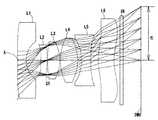
図1、図3、図5、図7、図9、図11、および図14はそれぞれ、本発明の実施形態の実施例1から7に係る撮像レンズの概略構成図を示している。 1, FIG. 3, FIG. 5, FIG. 7, FIG. 9, FIG. 11, and FIG. 14 show schematic configuration diagrams of the imaging lenses according to the first to seventh embodiments of the embodiment of the present invention, respectively.
本実施形態の撮像レンズは、物体側から像側に向かって順に配置された、光軸Xの近傍で負の屈折力を有する第1レンズL1と、光軸Xの近傍で物体側に凸面を向けた正の屈折力を有する第2レンズL2と、光軸Xの近傍で正の屈折力を有する第3レンズL3と、第4レンズL4と、光軸Xの近傍で物体側に凹面を向けた第5レンズL5と、光軸Xの近傍で像側に凹面を向けた第6レンズL6とから構成される。 The imaging lens of the present embodiment has a first lens L1 having a negative refractive force near the optical axis X, which is arranged in order from the object side toward the image side, and a convex surface toward the object side near the optical axis X. The second lens L2 having a positive refractive force, the third lens L3 having a positive refractive force in the vicinity of the optical axis X, the fourth lens L4, and the concave surface facing the object side in the vicinity of the optical axis X. It is composed of a fifth lens L5 and a sixth lens L6 having a concave surface facing the image side in the vicinity of the optical axis X.
また、第6レンズL6と撮像面IMG(すなわち、撮像素子の撮像面)の間には赤外線カットフィルタやカバーガラス等のフィルタIRが配置されている。なお、このフィルタIRは省略することが可能である。 Further, a filter IR such as an infrared cut filter or a cover glass is arranged between the sixth lens L6 and the image pickup surface IMG (that is, the image pickup surface of the image pickup element). The filter IR can be omitted.
開口絞りSTは、第2レンズL2と第3レンズL3の間に配置しているため、歪曲収差の補正を容易にしている。なお、開口絞りSTの位置は、第2レンズL2と第3レンズL3の間に限定されない。撮像素子の仕様に応じて適宜配置すればよい。 Since the aperture stop ST is arranged between the second lens L2 and the third lens L3, it is easy to correct the distortion. The position of the aperture stop ST is not limited to between the second lens L2 and the third lens L3. It may be appropriately arranged according to the specifications of the image sensor.
第1レンズL1は、負の屈折力を有し、光軸Xの近傍で物体側は平面であるとともに、像側に凹面を向けた平凹形状に形成されている。そのため、屈折力を強めることで、広角化を図るとともに、非点収差、歪曲収差を抑制している。また、光軸Xの近傍で物体側を平面とすることにより、撮像レンズ全系の焦点距離に影響を与えること無く、物体側に形成した非球面形状によって、非点収差、歪曲収差を抑制している。 The first lens L1 has a negative refractive power, and is formed in a flat concave shape with a concave surface facing the image side as well as a flat surface on the object side in the vicinity of the optical axis X. Therefore, by strengthening the refractive power, the angle is widened and astigmatism and distortion are suppressed. Further, by making the object side flat in the vicinity of the optical axis X, astigmatism and distortion are suppressed by the aspherical shape formed on the object side without affecting the focal length of the entire imaging lens system. ing.
なお、第1レンズL1の形状は、図5、図7、および図9に示す実施例3、実施例4、および実施例5のように、光軸Xの近傍で物体側に凹面を向けているとともに、像側に凹面を向けた両凹形状であってもよい。この場合、両面の負の屈折力により、広角化に有利になる。 The shape of the first lens L1 is such that the concave surface faces the object side in the vicinity of the optical axis X as in the third, fourth, and fifth embodiments shown in FIGS. 5, 7, and 9. At the same time, it may have a biconcave shape with the concave surface facing the image side. In this case, the negative refractive power on both sides is advantageous for widening the angle.
第2レンズL2は、正の屈折力を有し、光軸Xの近傍で物体側に凸面を向けているとともに、像側に凸面を向けた両凸形状に形成されている。そのため、低背化を図るとともに、コマ収差、非点収差、歪曲収差を良好に補正している。また、光軸近傍で物体側に凸面を向けることにより、コマ収差、非点収差をより良好に補正している。 The second lens L2 has a positive refractive power, and is formed in a biconvex shape in which the convex surface is directed toward the object side and the convex surface is directed toward the image side in the vicinity of the optical axis X. Therefore, the height is reduced and coma, astigmatism, and distortion are satisfactorily corrected. Further, by directing the convex surface toward the object near the optical axis, coma aberration and astigmatism are corrected more satisfactorily.
なお、第2レンズL2の形状は、図5、図7、図9、図11、および図13に示す実施例3、実施例4、実施例5、実施例6、および実施例7のように、光軸Xの近傍で物体側に凸面を向けているとともに、像側に凹面を向けたメニスカス形状であってもよい。この場合、歪曲収差の良好な補正が可能になる。 The shape of the second lens L2 is the same as in the third, fourth, fifth, sixth, and seventh embodiments shown in FIGS. 5, 7, 9, 11, and 13. The meniscus shape may be such that the convex surface is directed toward the object side and the concave surface is directed toward the image side in the vicinity of the optical axis X. In this case, good correction of distortion can be achieved.
第3レンズL3は、正の屈折力を有し、光軸Xの近傍で物体側に凹面を向けているとともに、像側に凸面を向けたメニスカス形状に形成されている。そのため、低背化を図るとともに、球面収差、コマ収差、像面湾曲、歪曲収差を良好に補正している。 The third lens L3 has a positive refractive power and is formed in a meniscus shape with a concave surface facing the object side and a convex surface facing the image side in the vicinity of the optical axis X. Therefore, the height is reduced, and spherical aberration, coma, curvature of field, and distortion are satisfactorily corrected.
なお、第3レンズL3の形状は、図5、図7、図9、図11、および図13に示す実施例3、実施例4、実施例5、実施例6、および実施例7のように、光軸Xの近傍で物体側に凸面を向けているとともに、像側に凸面を向けた両凸形状であってもよい。この場合、両面の正の屈折力により、低背化に有利になる。 The shape of the third lens L3 is as shown in the third, fourth, fifth, sixth, and seventh embodiments shown in FIGS. 5, 7, 9, 11, and 13. , A biconvex shape may be formed in which the convex surface is directed toward the object side and the convex surface is directed toward the image side in the vicinity of the optical axis X. In this case, the positive refractive powers on both sides are advantageous for lowering the height.
第4レンズL4は、正の屈折力を有し、光軸Xの近傍で物体側に凸面を向けているとともに、像側に凸面を向けた両凸形状に形成されている。そのため、非点収差、像面湾曲、歪曲収差を良好に補正している。 The fourth lens L4 has a positive refractive power, and is formed in a biconvex shape in which the convex surface is directed toward the object side and the convex surface is directed toward the image side in the vicinity of the optical axis X. Therefore, astigmatism, curvature of field, and distortion are satisfactorily corrected.
なお、第4レンズL4の屈折力は、図13に示す実施例7のように、負であってもよい。この場合、色収差の補正に有利になる。 The refractive power of the fourth lens L4 may be negative as in Example 7 shown in FIG. In this case, it is advantageous for correcting chromatic aberration.
また、第4レンズL4の形状は、図11に示す実施例6のように、光軸Xの近傍で物体側に凹面を向けているとともに、像側に凸面を向けたメニスカス形状であってもよい。この場合、像面湾曲、歪曲収差の良好な補正が可能になる。さらに、第4レンズL4の形状は、図13に示す実施例7のように、光軸Xの近傍で物体側に凹面を向けているとともに、像側に凹面を向けた両凹形状であってもよい。この場合、両面の負の屈折力により、色収差の良好な補正が可能になる。 Further, the shape of the fourth lens L4 may be a meniscus shape in which the concave surface is directed toward the object side and the convex surface is directed toward the image side in the vicinity of the optical axis X, as in the sixth embodiment shown in FIG. Good. In this case, good correction of curvature of field and distortion can be achieved. Further, the shape of the fourth lens L4 is a biconcave shape in which the concave surface is directed toward the object side and the concave surface is directed toward the image side in the vicinity of the optical axis X, as in the seventh embodiment shown in FIG. May be good. In this case, the negative refractive power on both sides enables good correction of chromatic aberration.
第5レンズL5は、負の屈折力を有し、光軸Xの近傍で物体側に凹面を向けているとともに、像側に凹面を向けた両凹形状に形成されている。そのため、コマ収差、非点収差、歪曲収差を良好に補正している。また、光軸近傍で物体側に凹面を向けることにより、非点収差、歪曲収差をより良好に補正している。 The fifth lens L5 has a negative refractive power, and is formed in a biconcave shape with a concave surface facing the object side and a concave surface facing the image side in the vicinity of the optical axis X. Therefore, coma aberration, astigmatism, and distortion are satisfactorily corrected. Further, by directing the concave surface toward the object near the optical axis, astigmatism and distortion are corrected more satisfactorily.
なお、第5レンズL5の屈折力は、図13に示す実施例7のように、正であってもよい。この場合、低背化に有利になる。 The refractive power of the fifth lens L5 may be positive as in Example 7 shown in FIG. In this case, it is advantageous for lowering the height.
また、第5レンズL5の形状は、図5、図9、および図13に示す実施例3、実施例5、および実施例7のように、光軸Xの近傍で物体側に凹面を向けているとともに、像側に凸面を向けたメニスカス形状であってもよい。この場合、歪曲収差の良好な補正が可能になる。 Further, the shape of the fifth lens L5 is such that the concave surface faces the object side in the vicinity of the optical axis X as in the third, fifth, and seventh embodiments shown in FIGS. 5, 9, and 13. At the same time, it may have a meniscus shape with a convex surface facing the image side. In this case, good correction of distortion can be achieved.
第6レンズL6は、正の屈折力を有し、光軸Xの近傍で物体側に凸面を向けているとともに、像側に凹面を向けたメニスカス形状に形成されている。そのため、非点収差、像面湾曲、歪曲収差を良好に補正している。また、光軸Xの近傍で像側に凹面を向けることにより、低背化を維持しながらバックフォーカスを確保している。 The sixth lens L6 has a positive refractive power and is formed in a meniscus shape with a convex surface facing the object side and a concave surface facing the image side in the vicinity of the optical axis X. Therefore, astigmatism, curvature of field, and distortion are satisfactorily corrected. Further, by directing the concave surface toward the image side in the vicinity of the optical axis X, the back focus is secured while maintaining the low profile.
なお、第6レンズL6の屈折力は、図7、および図13に示す実施例4、および実施例7のように、負であってもよい。この場合、色収差の補正に有利になる。 The refractive power of the sixth lens L6 may be negative as in Examples 4 and 7 shown in FIGS. 7 and 13. In this case, it is advantageous for correcting chromatic aberration.
本実施の形態に係る撮像レンズは、第1レンズL1から第6レンズL6のすべてが、それぞれ単レンズで構成されていることが好ましい。単レンズのみの構成は、非球面を多用することができる。本実施形態においては、すべてのレンズ面に適切な非球面を形成することで、良好な諸収差の補正が行われている。また、接合レンズを採用する場合に比較して工数を削減できるため、低コストで製作することが可能となる。 In the imaging lens according to the present embodiment, it is preferable that all of the first lens L1 to the sixth lens L6 are composed of a single lens. Aspherical surfaces can be frequently used in the configuration of only a single lens. In the present embodiment, good correction of various aberrations is performed by forming an appropriate aspherical surface on all lens surfaces. In addition, since the man-hours can be reduced as compared with the case of adopting a bonded lens, it is possible to manufacture the lens at low cost.
また、本実施の形態に係る撮像レンズは、レンズにプラスチック材料を採用することで製造を容易にし、低コストでの大量生産を可能にしている。 Further, the image pickup lens according to the present embodiment facilitates manufacturing by adopting a plastic material for the lens, and enables mass production at low cost.
なお、採用するレンズ材料はプラスチック材料に限定されるものではない。ガラス材料を採用することで、さらなる高性能化を目指すことも可能である。また、すべてのレンズ面を非球面で形成することが望ましいが、要求される性能によっては、製造が容易な球面を採用してもよい。 The lens material used is not limited to the plastic material. By using glass material, it is possible to aim for even higher performance. Further, it is desirable to form all the lens surfaces with an aspherical surface, but depending on the required performance, a spherical surface that is easy to manufacture may be adopted.
本実施形態における撮像レンズは、以下の条件式(1)から(18)を満足することにより、好ましい効果を奏するものである。
(1)0.20<νd2/νd6<0.60
(2)12.50<|f6|/D6<90.00
(3)2.50<r12/r2/D6<7.00
(4)5.25<|f6|/f<50.00
(5)−45.00<|f6|/f1<−5.00
(6)−0.95<r2/r6<−0.40
(7)−1.00<r6/r12<−0.25
(8)0.75<r12/f<2.00
(9)0.20<T4/T5<1.70
(10)2.50<f3/D3<8.00
(11)0.50<|f5|/f<2.00
(12)−1.00<f1/|f5|<−0.30
(13)0.25<f3/|f4|<1.80
(14)−4.50<r6/D3<−1.65
(15)0.35<|r8|/r11<8.50
(16)−28.50<r9/f<−0.40
(17)0.70<r11/f<2.50
(18)1.50<r12/r2<3.30
ただし、
νd2:第2レンズL2のd線に対するアッべ数
νd6:第6レンズL6のd線に対するアッべ数
D3:第3レンズL3の光軸X上の厚み
D6:第6レンズL6の光軸X上の厚み
T4:第4レンズL4の像側の面から第5レンズL5の物体側の面までの光軸X上の距離
T5:第5レンズL5の像側の面から第6レンズL6の物体側の面までの光軸X上の距離
f:撮像レンズ全系の焦点距離
f1:第1レンズL1の焦点距離
f3:第3レンズL3の焦点距離
f4:第4レンズL4の焦点距離
f5:第5レンズL5の焦点距離
f6:第6レンズL6の焦点距離
r2:第1レンズL1の像側の面の近軸曲率半径
r6:第3レンズL3の像側の面の近軸曲率半径
r8:第4レンズL4の像側の面の近軸曲率半径
r9:第5レンズL5の物体側の面の近軸曲率半径
r11:第6レンズL6の物体側の面の近軸曲率半径
r12:第6レンズL6の像側の面の近軸曲率半径
なお、上記の各条件式をすべて満足する必要はなく、それぞれの条件式を単独に満たすことで、各条件式に対応した作用効果を得ることができる。The image pickup lens in the present embodiment exhibits a preferable effect by satisfying the following conditional expressions (1) to (18).
(1) 0.20 <νd2 / νd6 <0.60
(2) 12.50 << | f6 | / D6 <90.00
(3) 2.50 <r12 / r2 / D6 <7.00
(4) 5.25 << | f6 | / f <50.00
(5) -45.00 << | f6 | / f1 <-5.00
(6) -0.95 <r2 / r6 <-0.40
(7) -1.00 <r6 / r12 <-0.25
(8) 0.75 <r12 / f <2.00
(9) 0.20 <T4 / T5 <1.70
(10) 2.50 <f3 / D3 <8.00
(11) 0.50 << | f5 | / f <2.00
(12) -1.00 <f1 / | f5 | <-0.30
(13) 0.25 <f3 / | f4 | <1.80
(14) -4.50 <r6 / D3 <-1.65
(15) 0.35 << | r8 | / r11 <8.50
(16) -28.50 <r9 / f <-0.40
(17) 0.70 <r11 / f <2.50
(18) 1.50 <r12 / r2 <3.30
However,
νd2: Abbey number with respect to the d line of the second lens L2 νd6: Abbey number with respect to the d line of the sixth lens L6 D3: Thickness on the optical axis X of the third lens L3 D6: On the optical axis X of the sixth lens L6 Thickness T4: Distance on the optical axis X from the image side surface of the 4th lens L4 to the object side surface of the 5th lens L5 T5: The object side of the 6th lens L6 from the image side surface of the 5th lens L5 Distance on the optical axis X to the surface f: Focus distance of the entire imaging lens f1: Focus distance of the first lens L1 f3: Focus distance of the third lens L3 f4: Focus distance of the fourth lens L4 f5: Fifth Focal distance f6 of lens L5: Focal distance r2 of sixth lens L6: Near-axis radius of curvature r6 of image-side surface of first lens L1: Near-axis radius of curvature r8 of image-side surface of third lens L3: Fourth Near-axis radius of curvature r9 on the image-side surface of lens L4: Near-axis radius of curvature r11 on the object-side surface of the fifth lens L5: Near-axis radius of curvature r12 on the object-side surface of the sixth lens L6: 6th lens L6 Near-axis radius of curvature of the surface on the image side of the lens It is not necessary to satisfy all of the above conditional expressions, and by satisfying each conditional expression independently, it is possible to obtain an action effect corresponding to each conditional expression.
また、本実施形態における撮像レンズは、以下の条件式(1a)から(18a)を満足することにより、より好ましい効果を奏するものである。
(1a)0.30<νd2/νd6<0.50
(2a)15.50<|f6|/D6<85.50
(3a)3.00<r12/r2/D6<6.00
(4a)6.10<|f6|/f<43.50
(5a)−40.00<|f6|/f1<−6.00
(6a)−0.85<r2/r6<−0.50
(7a)−0.90<r6/r12<−0.40
(8a)0.95<r12/f<1.70
(9a)0.30<T4/T5<1.40
(10a)2.85<f3/D3<7.00
(11a)1.00<|f5|/f<1.80
(12a)−0.85<f1/|f5|<−0.50
(13a)0.40<f3/|f4|<1.60
(14a)−4.00<r6/D3<−1.90
(15a)0.50<|r8|/r11<7.00
(16a)−25.00<r9/f<−0.65
(17a)0.90<r11/f<2.00
(18a)1.75<r12/r2<2.90
ただし、各条件式の符号は前の段落での説明と同様である。Further, the image pickup lens in the present embodiment exerts a more preferable effect by satisfying the following conditional expressions (1a) to (18a).
(1a) 0.30 <νd2 / νd6 <0.50
(2a) 15.50 << | f6 | / D6 <85.50
(3a) 3.00 <r12 / r2 / D6 <6.00
(4a) 6.10 << | f6 | / f <43.50
(5a) -40.00 << | f6 | / f1 <-6.00
(6a) -0.85 <r2 / r6 <-0.50
(7a) −0.90 <r6 / r12 <−0.40
(8a) 0.95 <r12 / f <1.70
(9a) 0.30 <T4 / T5 <1.40
(10a) 2.85 <f3 / D3 <7.00
(11a) 1.00 << | f5 | / f <1.80
(12a) −0.85 <f1 / | f5 | <−0.50
(13a) 0.40 <f3 / | f4 | <1.60
(14a) -4.00 <r6 / D3 <-1.90
(15a) 0.50 << | r8 | / r11 <7.00
(16a) -25.00 <r9 / f <-0.65
(17a) 0.90 <r11 / f <2.00
(18a) 1.75 <r12 / r2 <2.90
However, the sign of each conditional expression is the same as the explanation in the previous paragraph.
本実施形態において、レンズ面の非球面に採用する非球面形状は、光軸方向の軸をZ、光軸に直交する方向の高さをH、近軸曲率半径をR、円錐係数をk、非球面係数をA4、A6、A8、A10、A12、A14、A16としたとき数式1により表わされる。 In the present embodiment, the aspherical shape adopted for the aspherical surface of the lens surface is Z for the axis in the optical axis direction, H for the height in the direction orthogonal to the optical axis, R for the paraxial radius of curvature, and k for the conical coefficient. It is expressed by Equation 1 when the aspherical coefficient is A4, A6, A8, A10, A12, A14, A16.

次に、本実施形態に係る撮像レンズの実施例を示す。各実施例において、fは撮像レンズ全系の焦点距離を、FnoはFナンバーを、ωは半画角を、ihは最大像高を、TTLは光学全長をそれぞれ示す。また、iは物体側から数えた面番号、rは近軸曲率半径、dは光軸上のレンズ面間の距離(面間隔)、Ndはd線(基準波長)の屈折率、νdはd線に対するアッベ数をそれぞれ示す。なお、非球面に関しては、面番号iの後に*(アスタリスク)の符号を付加して示す。 Next, an example of the imaging lens according to the present embodiment will be shown. In each embodiment, f indicates the focal length of the entire imaging lens system, Fno indicates the F number, ω indicates the half angle of view, ih indicates the maximum image height, and TTL indicates the optical overall length. Further, i is the surface number counted from the object side, r is the paraxial radius of curvature, d is the distance between the lens surfaces on the optical axis (plane spacing), Nd is the refractive index of the d line (reference wavelength), and νd is d. The Abbe number for each line is shown. The aspherical surface is indicated by adding a sign * (asterisk) after the surface number i.
(実施例1)(Example 1)
基本的なレンズデータを以下の表1に示す。 The basic lens data is shown in Table 1 below.
実施例1の撮像レンズは、表8に示すように条件式(1)から(18)を満たしている。 The image pickup lens of Example 1 satisfies the conditional expressions (1) to (18) as shown in Table 8.
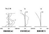
図2は実施例1の撮像レンズについて、球面収差(mm)、非点収差(mm)、歪曲収差(%)を示したものである。球面収差図は、F線(486nm)、d線(588nm)、C線(656nm)の各波長に対する収差量を示している。また、非点収差図にはサジタル像面Sにおけるd線の収差量(実線)、タンジェンシャル像面Tにおけるd線の収差量(破線)をそれぞれ示している(図4、図6、図8、図10、図12、および図14においても同じ)。図2に示すように、各収差は良好に補正されていることが分かる。 FIG. 2 shows spherical aberration (mm), astigmatism (mm), and distortion (%) of the image pickup lens of Example 1. The spherical aberration diagram shows the amount of aberration for each wavelength of the F line (486 nm), the d line (588 nm), and the C line (656 nm). The astigmatism diagram shows the amount of d-line aberration on the sagittal image plane S (solid line) and the amount of d-line aberration on the tangential image plane T (broken line) (FIGS. 4, 6, and 8). , The same applies to FIGS. 10, 12, and 14). As shown in FIG. 2, it can be seen that each aberration is satisfactorily corrected.
(実施例2)(Example 2)
基本的なレンズデータを以下の表2に示す。 The basic lens data is shown in Table 2 below.
実施例2の撮像レンズは、表8に示すように条件式(1)から(18)を満たしている。 The image pickup lens of Example 2 satisfies the conditional expressions (1) to (18) as shown in Table 8.
図4は実施例2の撮像レンズについて、球面収差(mm)、非点収差(mm)、歪曲収差(%)を示したものである。図4に示すように、各収差は良好に補正されていることが分かる。 FIG. 4 shows spherical aberration (mm), astigmatism (mm), and distortion (%) of the image pickup lens of Example 2. As shown in FIG. 4, it can be seen that each aberration is satisfactorily corrected.
(実施例3)(Example 3)
基本的なレンズデータを以下の表3に示す。 The basic lens data is shown in Table 3 below.
実施例3の撮像レンズは、表8に示すように条件式(1)から(18)を満たしている。 The image pickup lens of Example 3 satisfies the conditional expressions (1) to (18) as shown in Table 8.
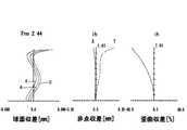
図6は実施例3の撮像レンズについて、球面収差(mm)、非点収差(mm)、歪曲収差(%)を示したものである。図6に示すように、各収差は良好に補正されていることが分かる。 FIG. 6 shows spherical aberration (mm), astigmatism (mm), and distortion (%) of the image pickup lens of Example 3. As shown in FIG. 6, it can be seen that each aberration is satisfactorily corrected.
(実施例4)(Example 4)
基本的なレンズデータを以下の表4に示す。 The basic lens data is shown in Table 4 below.
実施例4の撮像レンズは、表8に示すように条件式(1)から(18)を満たしている。 The image pickup lens of Example 4 satisfies the conditional expressions (1) to (18) as shown in Table 8.
図8は実施例4の撮像レンズについて、球面収差(mm)、非点収差(mm)、歪曲収差(%)を示したものである。図8に示すように、各収差は良好に補正されていることが分かる。 FIG. 8 shows spherical aberration (mm), astigmatism (mm), and distortion (%) of the image pickup lens of Example 4. As shown in FIG. 8, it can be seen that each aberration is satisfactorily corrected.
(実施例5)(Example 5)
基本的なレンズデータを以下の表5に示す。 The basic lens data is shown in Table 5 below.
実施例5の撮像レンズは、表8に示すように条件式(1)から(18)を満たしている。 The image pickup lens of Example 5 satisfies the conditional expressions (1) to (18) as shown in Table 8.
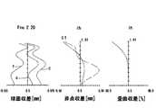
図10は実施例5の撮像レンズについて、球面収差(mm)、非点収差(mm)、歪曲収差(%)を示したものである。図10に示すように、各収差は良好に補正されていることが分かる。 FIG. 10 shows spherical aberration (mm), astigmatism (mm), and distortion (%) of the image pickup lens of Example 5. As shown in FIG. 10, it can be seen that each aberration is satisfactorily corrected.
(実施例6)(Example 6)
基本的なレンズデータを以下の表6に示す。 The basic lens data is shown in Table 6 below.
実施例6の撮像レンズは、表8に示すように条件式(1)から(18)を満たしている。 The image pickup lens of Example 6 satisfies the conditional expressions (1) to (18) as shown in Table 8.
図12は実施例6の撮像レンズについて、球面収差(mm)、非点収差(mm)、歪曲収差(%)を示したものである。図12に示すように、各収差は良好に補正されていることが分かる。 FIG. 12 shows spherical aberration (mm), astigmatism (mm), and distortion (%) of the image pickup lens of Example 6. As shown in FIG. 12, it can be seen that each aberration is satisfactorily corrected.
(実施例7)(Example 7)
基本的なレンズデータを以下の表7に示す。 The basic lens data is shown in Table 7 below.
実施例7の撮像レンズは、表8に示すように条件式(1)から(18)を満たしている。 The image pickup lens of Example 7 satisfies the conditional expressions (1) to (18) as shown in Table 8.
図14は実施例7の撮像レンズについて、球面収差(mm)、非点収差(mm)、歪曲収差(%)を示したものである。図14に示すように、各収差は良好に補正されていることが分かる。 FIG. 14 shows spherical aberration (mm), astigmatism (mm), and distortion (%) of the image pickup lens of Example 7. As shown in FIG. 14, it can be seen that each aberration is satisfactorily corrected.
表8に実施例1から実施例7に係る条件式(1)から(18)の値を示す。 Table 8 shows the values of the conditional expressions (1) to (18) according to the first to seventh embodiments.
本発明に係る撮像レンズを、カメラ機能を備える製品へ適用した場合、当該カメラの広角化、および低Fナンバー化への寄与とともに、高性能化を図ることができる。 When the image pickup lens according to the present invention is applied to a product having a camera function, it is possible to improve the performance as well as contribute to widening the angle and lowering the F number of the camera.
ST 開口絞り
L1 第1レンズ
L2 第2レンズ
L3 第3レンズ
L4 第4レンズ
L5 第5レンズ
L6 第6レンズ
ih 最大像高
IR フィルタ
IMG 撮像面
ST Aperture Aperture L1 1st lens L2 2nd lens L3 3rd lens L4 4th lens L5 5th lens L6 6th lens ih Maximum image height IR filter IMG imaging surface
Claims (7)
Translated fromJapanese(1)0.20<νd2/νd6<0.60
(2)12.50<|f6|/D6<90.00
(3)2.50<r12/r2/D6<7.00
ただし、
νd2:第2レンズのd線に対するアッべ数
νd6:第6レンズのd線に対するアッべ数
f6:第6レンズの焦点距離
D6:第6レンズの光軸上の厚み
r12:第6レンズの像側の面の近軸曲率半径
r2:第1レンズの像側の面の近軸曲率半径A first lens having a negative refractive power near the optical axis and a second lens having a positive refractive power with a convex surface facing the object side near the optical axis, arranged in order from the object side to the image side. A third lens having a positive refractive power near the optical axis, a fourth lens, a fifth lens with a concave surface facing the object side near the optical axis, and a sixth lens with a concave surface facing the image side near the optical axis. An imaging lens composed of and, which satisfies the following conditional equations (1), (2), and (3).
(1) 0.20 <νd2 / νd6 <0.60
(2) 12.50 << | f6 | / D6 <90.00
(3) 2.50 <r12 / r2 / D6 <7.00
However,
νd2: Abbey number for the d-line of the second lens νd6: Abbey number for the d-line of the sixth lens f6: Focal length of the sixth lens D6: Thickness on the optical axis of the sixth lens r12: Image of the sixth lens Paraxial curvature radius of the side surface r2: Paraxial curvature radius of the image side surface of the first lens
(4)5.25<|f6|/f<50.00
ただし、
f6:第6レンズの焦点距離
f:撮像レンズ全系の焦点距離The imaging lens according to claim 1, wherein the image pickup lens satisfies the following conditional expression (4).
(4) 5.25 << | f6 | / f <50.00
However,
f6: Focal length of the 6th lens f: Focal length of the entire imaging lens system
(5)−45.00<|f6|/f1<−5.00
ただし、
f6:第6レンズの焦点距離
f1:第1レンズの焦点距離The imaging lens according to claim 1, wherein the image pickup lens satisfies the following conditional expression (5).
(5) -45.00 << | f6 | / f1 <-5.00
However,
f6: Focal length of the 6th lens f1: Focal length of the 1st lens
(6)−0.95<r2/r6<−0.40
ただし、
r2:第1レンズの像側の面の近軸曲率半径
r6:第3レンズの像側の面の近軸曲率半径The imaging lens according to claim 1, wherein the image pickup lens satisfies the following conditional expression (6).
(6) -0.95 <r2 / r6 <-0.40
However,
r2: Paraxial radius of curvature of the image side surface of the first lens r6: Paraxial radius of curvature of the image side surface of the third lens
(7)−1.00<r6/r12<−0.25
ただし、
r6:第3レンズの像側の面の近軸曲率半径
r12:第6レンズの像側の面の近軸曲率半径The imaging lens according to claim 1, wherein the image pickup lens satisfies the following conditional expression (7).
(7) -1.00 <r6 / r12 <-0.25
However,
r6: Paraxial radius of curvature of the image side surface of the third lens r12: Paraxial radius of curvature of the image side surface of the sixth lens
(8)0.75<r12/f<2.00
ただし、
r12:第6レンズの像側の面の近軸曲率半径
f:撮像レンズ全系の焦点距離The imaging lens according to claim 1, wherein the image pickup lens satisfies the following conditional expression (8).
(8) 0.75 <r12 / f <2.00
However,
r12: Paraxial radius of curvature of the image side surface of the 6th lens f: Focal length of the entire imaging lens system
Priority Applications (4)
| Application Number | Priority Date | Filing Date | Title |
|---|---|---|---|
| JP2019205378AJP7449075B2 (en) | 2019-11-13 | 2019-11-13 | imaging lens |
| CN202011270041.4ACN112799210A (en) | 2019-11-13 | 2020-11-13 | camera lens |
| CN202022639687.7UCN215833683U (en) | 2019-11-13 | 2020-11-13 | Camera lens |
| US17/097,767US11822058B2 (en) | 2019-11-13 | 2020-11-13 | Imaging lens |
Applications Claiming Priority (1)
| Application Number | Priority Date | Filing Date | Title |
|---|---|---|---|
| JP2019205378AJP7449075B2 (en) | 2019-11-13 | 2019-11-13 | imaging lens |
Publications (2)
| Publication Number | Publication Date |
|---|---|
| JP2021076799Atrue JP2021076799A (en) | 2021-05-20 |
| JP7449075B2 JP7449075B2 (en) | 2024-03-13 |
Family
ID=75806132
Family Applications (1)
| Application Number | Title | Priority Date | Filing Date |
|---|---|---|---|
| JP2019205378AActiveJP7449075B2 (en) | 2019-11-13 | 2019-11-13 | imaging lens |
Country Status (3)
| Country | Link |
|---|---|
| US (1) | US11822058B2 (en) |
| JP (1) | JP7449075B2 (en) |
| CN (2) | CN215833683U (en) |
Families Citing this family (11)
| Publication number | Priority date | Publication date | Assignee | Title |
|---|---|---|---|---|
| JP7449075B2 (en)* | 2019-11-13 | 2024-03-13 | 東京晨美光学電子株式会社 | imaging lens |
| CN111965787B (en)* | 2020-08-25 | 2023-05-16 | 玉晶光电(厦门)有限公司 | Optical imaging lens |
| JP2022181228A (en)* | 2021-05-26 | 2022-12-08 | パナソニックIpマネジメント株式会社 | Imaging optical system and camera |
| CN113589480B (en)* | 2021-07-22 | 2023-04-28 | 东莞市长益光电有限公司 | High-low temperature resistant glass-plastic mixed fisheye lens with high cost performance |
| CN115963622B (en)* | 2021-10-13 | 2025-09-12 | 浙江舜宇光学有限公司 | Camera lens |
| CN114185157B (en)* | 2022-02-14 | 2022-07-22 | 江西联益光学有限公司 | Optical lens |
| TWI805283B (en)* | 2022-03-22 | 2023-06-11 | 紘立光電股份有限公司 | Optical imaging lens, imaging device and electronic device |
| TWI891130B (en)* | 2023-11-23 | 2025-07-21 | 紘立光電股份有限公司 | Optical imaging lens, imaging device and electronic device |
| CN117492174A (en)* | 2023-11-28 | 2024-02-02 | 江西联创电子有限公司 | Optical lens |
| CN117389011B (en)* | 2023-12-12 | 2024-03-19 | 联创电子科技股份有限公司 | Optical lens |
| CN118465974A (en)* | 2024-06-04 | 2024-08-09 | 厦门力鼎光电股份有限公司 | An optical imaging lens |
Citations (10)
| Publication number | Priority date | Publication date | Assignee | Title |
|---|---|---|---|---|
| JPH0727976A (en)* | 1993-07-08 | 1995-01-31 | Olympus Optical Co Ltd | Small-sized two-group zoom lens system |
| JP2005258294A (en)* | 2004-03-15 | 2005-09-22 | Casio Comput Co Ltd | Zoom lens |
| JP2006113404A (en)* | 2004-10-15 | 2006-04-27 | Konica Minolta Opto Inc | Variable power optical system, imaging lens device and digital apparatus |
| JP2007133133A (en)* | 2005-11-10 | 2007-05-31 | Olympus Imaging Corp | Zoom lens and imaging apparatus having the same |
| JP2007232997A (en)* | 2006-02-28 | 2007-09-13 | Casio Comput Co Ltd | Zoom lens and camera |
| JP2011175234A (en)* | 2010-01-29 | 2011-09-08 | Hoya Corp | Zoom lens system |
| JP2011203418A (en)* | 2010-03-25 | 2011-10-13 | Panasonic Corp | Zoom lens |
| US20160154211A1 (en)* | 2014-11-28 | 2016-06-02 | Samsung Electro-Mechanics Co., Ltd. | Optical system |
| JP6553270B1 (en)* | 2018-08-14 | 2019-07-31 | エーエーシー テクノロジーズ ピーティーイー リミテッド | Imaging optical lens |
| CN110297312A (en)* | 2019-06-29 | 2019-10-01 | 瑞声科技(新加坡)有限公司 | Camera optical camera lens |
Family Cites Families (6)
| Publication number | Priority date | Publication date | Assignee | Title |
|---|---|---|---|---|
| JP2004318101A (en)* | 2003-03-31 | 2004-11-11 | Konica Minolta Photo Imaging Inc | Zoom lens device |
| JP5752856B2 (en) | 2012-07-18 | 2015-07-22 | 富士フイルム株式会社 | Imaging lens and imaging device provided with imaging lens |
| CN109061849B (en)* | 2018-08-14 | 2020-10-23 | 瑞声光学解决方案私人有限公司 | Camera optics |
| CN109143543B (en)* | 2018-08-14 | 2020-12-22 | 瑞声光学解决方案私人有限公司 | Image pickup optical lens |
| JP2020109513A (en) | 2019-01-05 | 2020-07-16 | 日精テクノロジー株式会社 | Imaging lens and camera device |
| JP7449075B2 (en)* | 2019-11-13 | 2024-03-13 | 東京晨美光学電子株式会社 | imaging lens |
- 2019
- 2019-11-13JPJP2019205378Apatent/JP7449075B2/enactiveActive
- 2020
- 2020-11-13USUS17/097,767patent/US11822058B2/enactiveActive
- 2020-11-13CNCN202022639687.7Upatent/CN215833683U/enactiveActive
- 2020-11-13CNCN202011270041.4Apatent/CN112799210A/enactivePending
Patent Citations (10)
| Publication number | Priority date | Publication date | Assignee | Title |
|---|---|---|---|---|
| JPH0727976A (en)* | 1993-07-08 | 1995-01-31 | Olympus Optical Co Ltd | Small-sized two-group zoom lens system |
| JP2005258294A (en)* | 2004-03-15 | 2005-09-22 | Casio Comput Co Ltd | Zoom lens |
| JP2006113404A (en)* | 2004-10-15 | 2006-04-27 | Konica Minolta Opto Inc | Variable power optical system, imaging lens device and digital apparatus |
| JP2007133133A (en)* | 2005-11-10 | 2007-05-31 | Olympus Imaging Corp | Zoom lens and imaging apparatus having the same |
| JP2007232997A (en)* | 2006-02-28 | 2007-09-13 | Casio Comput Co Ltd | Zoom lens and camera |
| JP2011175234A (en)* | 2010-01-29 | 2011-09-08 | Hoya Corp | Zoom lens system |
| JP2011203418A (en)* | 2010-03-25 | 2011-10-13 | Panasonic Corp | Zoom lens |
| US20160154211A1 (en)* | 2014-11-28 | 2016-06-02 | Samsung Electro-Mechanics Co., Ltd. | Optical system |
| JP6553270B1 (en)* | 2018-08-14 | 2019-07-31 | エーエーシー テクノロジーズ ピーティーイー リミテッド | Imaging optical lens |
| CN110297312A (en)* | 2019-06-29 | 2019-10-01 | 瑞声科技(新加坡)有限公司 | Camera optical camera lens |
Also Published As
| Publication number | Publication date |
|---|---|
| US20210389571A1 (en) | 2021-12-16 |
| CN215833683U (en) | 2022-02-15 |
| JP7449075B2 (en) | 2024-03-13 |
| CN112799210A (en) | 2021-05-14 |
| US11822058B2 (en) | 2023-11-21 |
Similar Documents
| Publication | Publication Date | Title |
|---|---|---|
| JP6843476B2 (en) | Imaging lens | |
| JP6882838B2 (en) | Imaging lens | |
| JP6814521B2 (en) | Imaging lens | |
| JP6709564B2 (en) | Imaging lens | |
| JP6821276B2 (en) | Imaging lens | |
| JP6726916B2 (en) | Imaging lens | |
| JP6865445B2 (en) | Imaging lens | |
| JP7449075B2 (en) | imaging lens | |
| JP6769683B2 (en) | Imaging lens | |
| JP7002508B2 (en) | Imaging lens | |
| JP6814519B2 (en) | Imaging lens | |
| JP2019197088A (en) | Imaging lens | |
| JP7319049B2 (en) | imaging lens | |
| JP6807139B2 (en) | Imaging lens | |
| JP2021189245A (en) | Imaging lens | |
| JP6854576B2 (en) | Imaging lens | |
| JP2021043441A (en) | Image capturing lens | |
| JP2019184723A (en) | Image capturing lens | |
| JP2022163952A (en) | imaging lens | |
| JP2022034768A (en) | Image capturing lens | |
| JP2021173906A (en) | Imaging lens | |
| JP2021162805A (en) | Image capturing lens | |
| JP6887740B2 (en) | Imaging lens | |
| JP2022083330A (en) | Imaging lens | |
| JP7011986B2 (en) | Imaging lens |
Legal Events
| Date | Code | Title | Description |
|---|---|---|---|
| A711 | Notification of change in applicant | Free format text:JAPANESE INTERMEDIATE CODE: A711 Effective date:20210810 | |
| A521 | Request for written amendment filed | Free format text:JAPANESE INTERMEDIATE CODE: A523 Effective date:20211008 | |
| A621 | Written request for application examination | Free format text:JAPANESE INTERMEDIATE CODE: A621 Effective date:20221108 | |
| A977 | Report on retrieval | Free format text:JAPANESE INTERMEDIATE CODE: A971007 Effective date:20230714 | |
| A131 | Notification of reasons for refusal | Free format text:JAPANESE INTERMEDIATE CODE: A131 Effective date:20230725 | |
| A521 | Request for written amendment filed | Free format text:JAPANESE INTERMEDIATE CODE: A523 Effective date:20230925 | |
| A02 | Decision of refusal | Free format text:JAPANESE INTERMEDIATE CODE: A02 Effective date:20231003 | |
| A521 | Request for written amendment filed | Free format text:JAPANESE INTERMEDIATE CODE: A523 Effective date:20240104 | |
| A911 | Transfer to examiner for re-examination before appeal (zenchi) | Free format text:JAPANESE INTERMEDIATE CODE: A911 Effective date:20240112 | |
| TRDD | Decision of grant or rejection written | ||
| A01 | Written decision to grant a patent or to grant a registration (utility model) | Free format text:JAPANESE INTERMEDIATE CODE: A01 Effective date:20240131 | |
| A61 | First payment of annual fees (during grant procedure) | Free format text:JAPANESE INTERMEDIATE CODE: A61 Effective date:20240301 | |
| R150 | Certificate of patent or registration of utility model | Ref document number:7449075 Country of ref document:JP Free format text:JAPANESE INTERMEDIATE CODE: R150 |