Movatterモバイル変換


[0]ホーム

URL:


JP2021074834A - Grinding device - Google Patents

Grinding device
Download PDF

Info

Publication number
JP2021074834A
JP2021074834AJP2019204308AJP2019204308AJP2021074834AJP 2021074834 AJP2021074834 AJP 2021074834AJP 2019204308 AJP2019204308 AJP 2019204308AJP 2019204308 AJP2019204308 AJP 2019204308AJP 2021074834 AJP2021074834 AJP 2021074834A
Authority
JP
Japan
Prior art keywords
grinding
grindstone
pushing force
contacts
contactor
Prior art date
Legal status (The legal status is an assumption and is not a legal conclusion. Google has not performed a legal analysis and makes no representation as to the accuracy of the status listed.)
Granted
Application number
JP2019204308A
Other languages
Japanese (ja)
Other versions
JP7395973B2 (en
Inventor
良太 川井
Ryota Kawai
良太 川井
明 渡邉
Akira Watanabe
明 渡邉
水谷 吉宏
Yoshihiro Mizutani
吉宏 水谷
Current Assignee (The listed assignees may be inaccurate. Google has not performed a legal analysis and makes no representation or warranty as to the accuracy of the list.)
JTEKT Corp
Original Assignee
JTEKT Corp
Priority date (The priority date is an assumption and is not a legal conclusion. Google has not performed a legal analysis and makes no representation as to the accuracy of the date listed.)
Filing date
Publication date
Application filed by JTEKT CorpfiledCriticalJTEKT Corp
Priority to JP2019204308ApriorityCriticalpatent/JP7395973B2/en
Publication of JP2021074834ApublicationCriticalpatent/JP2021074834A/en
Application grantedgrantedCritical
Publication of JP7395973B2publicationCriticalpatent/JP7395973B2/en
Activelegal-statusCriticalCurrent
Anticipated expirationlegal-statusCritical

Links

Images

Landscapes

Abstract

Translated fromJapanese

【課題】研削時における研削対象物の外径変化の影響による加工精度の悪化を抑制可能な研削装置を提供する。【解決手段】砥石2が取り付けられ、砥石2を回転させる砥石台3と、軸状の研削対象物7を回転可能に保持する主軸台4と、を備え、砥石2と研削対象物7とを軸方向に相対移動させつつ砥石2により研削対象物7を研削する研削装置1であって、軸方向に並んで配置され、砥石2により研削対象物7を研削する際に、研削対象物7に押し付けられ研削対象物7のたわみを抑制する第1及び第2の接触子11a,11bを有するレスト装置6と、レスト装置6を制御する制御装置20と、を備え、制御装置20は、第1及び第2の接触子11a,11bの合計の押込み力を一定に維持しつつ、砥石2と研削対象物7との相対移動に伴って、第1及び第2の接触子11a,11bの押込み力をそれぞれ増減する接触子制御部21を有する。【選択図】図1PROBLEM TO BE SOLVED: To provide a grinding apparatus capable of suppressing deterioration of machining accuracy due to the influence of a change in the outer diameter of an object to be ground during grinding. SOLUTION: The grindstone 2 is attached and a grindstone base 3 for rotating the grindstone 2 and a spindle base 4 for rotatably holding a shaft-shaped grinding object 7 are provided, and the grindstone 2 and the grinding object 7 are provided. A grinding device 1 that grinds a grinding object 7 with a grindstone 2 while moving relative to the axial direction. It is arranged side by side in the axial direction, and when the grindstone 2 grinds the grinding object 7, the grinding object 7 is subjected to. A rest device 6 having first and second contacts 11a and 11b that are pressed to suppress the deflection of the grinding object 7 and a control device 20 that controls the rest device 6 are provided, and the control device 20 is the first. While maintaining the total pushing force of the second contacts 11a and 11b constant, the pushing force of the first and second contacts 11a and 11b as the grindstone 2 and the grinding object 7 move relative to each other. Each has a contactor control unit 21 that increases or decreases the number of wheels. [Selection diagram] Fig. 1

Description

Translated fromJapanese

本発明は、レスト装置を備えた研削装置に関する。 The present invention relates to a grinding device including a rest device.

砥石が取り付けられ砥石を回転させる砥石台と、軸状の研削対象物を回転可能に保持する主軸台と、を備え、回転する砥石を軸方向に移動させつつ研削対象物を研削する研削装置が知られている。このような研削装置として、砥石により研削対象物を研削する際に、接触子を研削対象物に押し付けて研削対象物のたわみを抑制するレスト装置を備えたものが知られている(例えば、特許文献1参照)。 A grinding device that has a grindstone base on which a grindstone is attached to rotate the grindstone and a spindle base that rotatably holds a shaft-shaped grinding object, and grinds the grinding object while moving the rotating grindstone in the axial direction. Are known. As such a grinding device, there is known one provided with a rest device that presses a contact against the object to be ground to suppress the deflection of the object to be ground when grinding the object to be ground with a grindstone (for example, a patent). Reference 1).

特許第2602965号公報Japanese Patent No. 2602965

従来の研削装置では、砥石がレスト装置の接触子と対向する位置を通過する際に、研削による研削対象物の外径変化、すなわち研削済み部分と未研削部分との間の段差の影響により、研削対象物と接触子とが非接触となる瞬間が生じ、研削対象物に接触子が再度接触する際に研削対象物が振動して加工精度が悪化する場合があった。 In a conventional grinding device, when the grindstone passes through a position facing the contactor of the rest device, the outer diameter of the object to be ground is changed by grinding, that is, due to the influence of the step between the ground portion and the unground portion. There was a moment when the object to be ground and the contact were not in contact with each other, and when the contact was brought into contact with the object to be ground again, the object to be ground vibrated and the machining accuracy was deteriorated.

そこで、本発明は、研削時における研削対象物の外径変化の影響による加工精度の悪化を抑制可能な研削装置を提供することを目的とする。 Therefore, an object of the present invention is to provide a grinding apparatus capable of suppressing deterioration of machining accuracy due to the influence of a change in the outer diameter of a grinding object during grinding.

本発明は、上記課題を解決することを目的として、砥石が取り付けられ、前記砥石を回転させる砥石台と、軸状の研削対象物を回転可能に保持する主軸台と、を備え、前記砥石と前記研削対象物とを軸方向に相対移動させつつ前記砥石により前記研削対象物を研削する研削装置であって、軸方向に並んで配置され、前記砥石により前記研削対象物を研削する際に、前記研削対象物に押し付けられ前記研削対象物のたわみを抑制する第1及び第2の接触子を有するレスト装置と、前記レスト装置を制御する制御装置と、を備え、前記制御装置は、前記第1及び第2の接触子の合計の押込み力を一定に維持しつつ、前記砥石と前記研削対象物との相対移動に伴って、前記第1及び第2の接触子の押込み力をそれぞれ増減する接触子制御部を有する、研削装置を提供する。 The present invention is provided with a grindstone base on which a grindstone is attached to rotate the grindstone, and a spindle base for rotatably holding a shaft-shaped grinding object, for the purpose of solving the above problems. A grinding device that grinds the grinding object with the grindstone while moving the grinding object relative to the axial direction. When the grinding object is arranged side by side in the axial direction and the grinding object is ground with the grindstone, the grinding object is ground. A rest device having first and second contacts that are pressed against the grinding object and suppress the deflection of the grinding object, and a control device that controls the rest device are provided, and the control device is the first. While maintaining the total pushing force of the first and second contacts constant, the pushing force of the first and second contacts is increased or decreased as the grindstone and the object to be ground move relative to each other. Provided is a grinding device having a contactor control unit.

本発明によれば、研削時における研削対象物の外径変化の影響による加工精度の悪化を抑制可能な研削装置を提供できる。 According to the present invention, it is possible to provide a grinding apparatus capable of suppressing deterioration of machining accuracy due to the influence of a change in the outer diameter of a grinding object during grinding.

本発明の一実施の形態に係る研削装置の模式図である。It is a schematic diagram of the grinding apparatus which concerns on one Embodiment of this invention.研削対象物の回転軸方向に沿って見た場合の第1及び第2レスト装置の構成例を示す概略構成図である。It is a schematic block diagram which shows the structural example of the 1st and 2nd rest devices when viewed along the rotation axis direction of the object to be ground.(a)〜(d)は、第1及び第2接触子の動作を説明する図である。(A) to (d) are diagrams for explaining the operation of the first and second contacts.第1及び第2の接触子の押込み力、およびその合計の押込み力の時間変化の一例を示すグラフ図である。It is a graph which shows an example of the time change of the pushing force of the 1st and 2nd contactors, and the pushing force of the total pushing force.研削時の制御フローの一例を示すフロー図である。It is a flow figure which shows an example of the control flow at the time of grinding.

[実施の形態]
本発明の実施の形態について、図1乃至図5を参照して説明する。なお、以下に説明する実施の形態は、本発明を実施する上での好適な具体例として示すものであり、技術的に好ましい種々の技術的事項を具体的に例示している部分もあるが、本発明の技術的範囲は、この具体的態様に限定されるものではない。
[Embodiment]
Embodiments of the present invention will be described with reference to FIGS. 1 to 5. It should be noted that the embodiments described below are shown as suitable specific examples for carrying out the present invention, and there are some parts that specifically exemplify various technically preferable technical matters. , The technical scope of the present invention is not limited to this specific aspect.

(研削装置の全体構成)
図1は、本実施の形態に係る研削装置の模式図である。図1に示すように、研削装置1は、砥石2が取り付けられ、砥石2を回転させる砥石台3と、砥石2の回転軸と平行な方向(研削対象物7の軸方向)に移動可能に設けられたテーブル8と、軸状の研削対象物7を回転可能に保持する主軸台4及び心押台5と、研削時に研削対象物のたわみを抑制するためのレスト装置6と、レスト装置6を制御する制御装置20と、を備えている。
(Overall configuration of grinding equipment)
FIG. 1 is a schematic view of a grinding device according to the present embodiment. As shown in FIG. 1, thegrinding device 1 is movable in a direction parallel to the rotation axis of the grindstone 2 (the axial direction of the grinding object 7) and thegrindstone base 3 on which thegrindstone 2 is attached to rotate thegrindstone 2. A table 8 provided, aheadstock 4 and atailstock 5 for rotatably holding a shaft-shaped object 7 to be ground, arest device 6 for suppressing bending of the object to be ground during grinding, and arest device 6 20 and acontrol device 20 for controlling the above.

砥石台3及び主軸台4は、ベッド10上に載置されている。研削装置1では、砥石台3は、砥石2の回転軸と垂直な方向(砥石2の切込方向)に移動可能に設けられている。砥石台3は、サーボモータ30、エンコーダ31、図略のボールネジを介して砥石2の切込方向に送り制御されている。主軸台4は、心押台5と対向配置されており、研削対象物7を主軸台4と心押台5とで挟み込むことで、研削対象物7を回転可能に支持するように構成されている。 Thegrindstone base 3 and thespindle base 4 are placed on thebed 10. In thegrinding device 1, thegrindstone base 3 is provided so as to be movable in a direction perpendicular to the rotation axis of the grindstone 2 (cutting direction of the grindstone 2). Thegrindstone base 3 is feed-controlled in the cutting direction of thegrindstone 2 via aservomotor 30, anencoder 31, and a ball screw (not shown). Theheadstock 4 is arranged to face thetailstock 5, and is configured to rotatably support thegrinding object 7 by sandwiching thegrinding object 7 between theheadstock 4 and thetailstock 5. There is.

レスト装置6、主軸台4及び心押台5は、テーブル8上に載置されている。研削装置1では、砥石台3を移動させて砥石2を研削対象物7に近づけ、回転する砥石2を研削対象物7に切り込んだ状態で、テーブル8を移動させることで、砥石2と研削対象物7とを軸方向に相対移動させつつ、回転する砥石2により研削対象物7を研削するように構成されている。テーブル8は、サーボモータ40、エンコーダ41、図略のボールネジを介して研削対象物7の軸方向に送り制御されている。研削対象物7は、その長手方向に垂直な断面が円形状である長尺物である。 Therest device 6, thespindle base 4, and thetailstock 5 are placed on the table 8. In thegrinding device 1, the grindstone table 3 is moved to bring thegrindstone 2 closer to the object to beground 7, and therotating grindstone 2 is cut into the object to beground 7, and the table 8 is moved to move thegrindstone 2 and the object to be ground. It is configured to grind theobject 7 to be ground by therotating grindstone 2 while relatively moving theobject 7 in the axial direction. The table 8 is fed and controlled in the axial direction of theobject 7 to be ground via theservomotor 40, theencoder 41, and the ball screw (not shown). The object to beground 7 is a long object having a circular cross section perpendicular to the longitudinal direction thereof.

(レスト装置6)
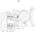
図2は、研削対象物7の回転軸線に沿って軸方向から見たレスト装置6の構成例を研削対象物7及び砥石2の一部と共に示す模式図である。図2では、砥石2及び研削対象物7の回転方向を矢印で示している。以下の説明において、「上」「下」とは、鉛直方向の上下をいうものとする。
(Rest device 6)
FIG. 2 is a schematic view showing a configuration example of therest device 6 viewed from the axial direction along the rotation axis of thegrinding object 7 together with a part of thegrinding object 7 and thegrindstone 2. In FIG. 2, the rotation directions of thegrindstone 2 and the object to beground 7 are indicated by arrows. In the following description, "upper" and "lower" shall mean up and down in the vertical direction.

レスト装置6は、砥石2により研削対象物7を研削する際に、砥石2の負荷により研削対象物7がたわんでしまうことを抑制するためのものである。レスト装置6は、主軸台4及び心押台5と共にテーブル8上に載置されており、研削対象物7との相対位置が一定の位置となるようにテーブル8に固定されている。レスト装置6は、研削対象物7の軸方向中央部を支持するように設けられている。 Therest device 6 is for suppressing the bending of thegrinding object 7 due to the load of thegrindstone 2 when thegrinding object 7 is ground by thegrindstone 2. Therest device 6 is placed on the table 8 together with thespindle base 4 and thetailstock 5, and is fixed to the table 8 so that the relative position with respect to thegrinding object 7 is a constant position. Therest device 6 is provided so as to support the axially central portion of theobject 7 to be ground.

本実施の形態では、レスト装置6は、第1の接触子(シュー)11aを有する第1のレスト装置6aと、第2の接触子(シュー)11bを有する第2のレスト装置6bと、を有している。第1及び第2の接触子11a,11bは、軸方向に並んで配置されており、砥石2により研削対象物7を研削する際に、研削対象物7に押し付けられ研削対象物7のたわみを抑制する役割を果たす。 In the present embodiment, therest device 6 comprises afirst rest device 6a having a first contact (shoe) 11a and asecond rest device 6b having a second contact (shoe) 11b. Have. The first andsecond contacts 11a and 11b are arranged side by side in the axial direction, and when thegrinding object 7 is ground by thegrindstone 2, the first andsecond contacts 11a and 11b are pressed against thegrinding object 7 to cause the deflection of thegrinding object 7 to be deflected. It plays a suppressive role.

本実施の形態では、第1及び第2のレスト装置6a,6bは、研削対象物7の軸方向視において砥石2とは反対側に配置された第1のレスト機構部61と、第1のレスト機構部61よりも下方に配置された第2のレスト機構部62と、テーブル8に取り付けられた支持体63と、をそれぞれ有している。第1及び第2のレスト機構部61,62は、支持体63に支持されている。 In the present embodiment, the first andsecond rest devices 6a and 6b are the firstrest mechanism portion 61 and the firstrest mechanism portion 61 arranged on the side opposite to thegrindstone 2 in the axial view of thegrinding object 7. It has a secondrest mechanism portion 62 arranged below therest mechanism portion 61, and asupport 63 attached to the table 8, respectively. The first and secondrest mechanism portions 61 and 62 are supported by thesupport 63.

第1のレスト機構部61は、支持体63に固定された第1のケース部材611と、第1のケース部材611に固定された第1のサーボモータ612と、カップリング613を介して第1のサーボモータ612の出力軸612aに連結されたボールねじシャフト614と、ボールねじシャフト614の外周に配置されたボールねじナット615と、ボールねじシャフト614の回転によりボールねじナット615と共に進退移動する第1の作動部材616と、第1の作動部材616にボルト113を介して取り付けられた接触子111とを有している。接触子111は、研削対象物7における砥石2側とは反対側の外周面に接する接触面111aを有している。 The firstrest mechanism portion 61 is first via afirst case member 611 fixed to thesupport 63, afirst servomotor 612 fixed to thefirst case member 611, and acoupling 613. Theball screw shaft 614 connected to theoutput shaft 612a of theservomotor 612, theball screw nut 615 arranged on the outer periphery of theball screw shaft 614, and theball screw nut 614 move forward and backward together with theball screw shaft 614. It has a workingmember 616 of No. 1 and acontactor 111 attached to the first workingmember 616 via abolt 113. Thecontactor 111 has acontact surface 111a in contact with the outer peripheral surface of theobject 7 to be ground, which is opposite to thegrindstone 2 side.

第1のサーボモータ612は、第1の作動部材616を動作させるアクチュエータであり、制御装置20から供給されるモータ電流によってトルクを発生し、ボールねじシャフト614を回転駆動する。ボールねじナット615は、第1のケース部材611に対して回り止めされており、第1の作動部材616は、ボールねじシャフト614の回転軸線に沿って直線移動可能に第1のケース部材611に案内支持されている。第1のサーボモータ612によってボールねじシャフト614が一方向に回転駆動されると、第1の作動部材616が研削対象物7に向かって前進し、接触子111が研削対象物7の軸方向中央部に当接する。また、ボールねじシャフト614が逆方向に回転駆動されると、接触子111が研削対象物7から離間する。 Thefirst servomotor 612 is an actuator that operates thefirst operating member 616, generates torque by the motor current supplied from thecontrol device 20, and rotationally drives theball screw shaft 614. Theball screw nut 615 is detented with respect to thefirst case member 611, and thefirst operating member 616 is moved linearly along the rotation axis of theball screw shaft 614 to thefirst case member 611. Guidance is supported. When theball screw shaft 614 is rotationally driven in one direction by thefirst servomotor 612, thefirst operating member 616 advances toward thegrinding object 7, and thecontact 111 is axially centered on thegrinding object 7. Contact the part. Further, when theball screw shaft 614 is rotationally driven in the opposite direction, thecontact 111 is separated from theobject 7 to be ground.

第2のレスト機構部62は、第1のケース部材611よりも下方で支持体63に固定された第2のケース部材621と、第2のケース部材621に固定された第2のサーボモータ622と、カップリング623を介して第2のサーボモータ622の出力軸622aに連結されたボールねじシャフト624と、ボールねじシャフト624の外周に配置されたボールねじナット625と、ボールねじシャフト624の回転によりボールねじナット625と共に進退移動するロッド626と、ロッド626の進退移動に伴って、支持体63に設けられた支持軸631を中心として回動する第2の作動部材627と、第2の作動部材627にボルト114を介して取り付けられた接触子112とを有している。接触子112は、研削対象物7の下端部における外周面に接する接触面112aを有している。 The secondrest mechanism portion 62 includes asecond case member 621 fixed to thesupport 63 below thefirst case member 611, and asecond servomotor 622 fixed to thesecond case member 621. Theball screw shaft 624 connected to theoutput shaft 622a of thesecond servomotor 622 via thecoupling 623, theball screw nut 625 arranged on the outer periphery of theball screw shaft 624, and the rotation of theball screw shaft 624. Arod 626 that moves forward and backward together with theball screw nut 625, asecond operating member 627 that rotates about asupport shaft 631 provided on thesupport 63 as therod 626 moves forward and backward, and a second operation. It has acontact 112 attached to themember 627 via abolt 114. Thecontactor 112 has acontact surface 112a in contact with the outer peripheral surface at the lower end of theobject 7 to be ground.

第2のサーボモータ622は、第2の作動部材627を動作させるアクチュエータであり、制御装置20から供給されるモータ電流によってトルクを発生し、ボールねじシャフト624を回転駆動する。ボールねじナット625は、第2のケース部材621に対して回り止めされており、ロッド626は、ボールねじシャフト624の回転軸線に沿って直線移動可能に第2のケース部材621に案内支持されている。ロッド626と第2の作動部材627とは、ピボット軸629によって回動可能に連結されている。第2のサーボモータ622によってボールねじシャフト624が一方向に回転駆動されると、ロッド626が第2のケース部材621から突出して第2の作動部材627が支持軸631を中心として回動し、接触子112が研削対象物7の軸方向中央部に当接する。また、ボールねじシャフト624が逆方向に回転駆動されると、接触子112が研削対象物7から離間する。なお、第2のレスト機構部62は必須ではなく、省略可能である。 Thesecond servomotor 622 is an actuator that operates thesecond operating member 627, generates torque by the motor current supplied from thecontrol device 20, and rotationally drives theball screw shaft 624. Theball screw nut 625 is prevented from rotating with respect to thesecond case member 621, and therod 626 is guided and supported by thesecond case member 621 so as to be linearly movable along the rotation axis of theball screw shaft 624. There is. Therod 626 and thesecond operating member 627 are rotatably connected by apivot shaft 629. When theball screw shaft 624 is rotationally driven by thesecond servomotor 622 in one direction, therod 626 protrudes from thesecond case member 621 and thesecond operating member 627 rotates about thesupport shaft 631. Thecontact 112 comes into contact with the axially central portion of theobject 7 to be ground. Further, when theball screw shaft 624 is rotationally driven in the opposite direction, thecontact 112 is separated from theobject 7 to be ground. The secondrest mechanism portion 62 is not essential and can be omitted.

第1及び第2の接触子11a,11b(接触子111,112)は、超硬性の材料からなり、例えばダイヤモンドの微粒子を焼結したダイヤモンド焼結体であるダイヤモンドコンパックスを第1及び第2の接触子11a,11bの材料として好適に用いることができる。 The first andsecond contacts 11a and 11b (contacts 111 and 112) are made of a superhard material, and for example, diamond compaq, which is a diamond sintered body obtained by sintering fine diamond particles, is used as the first and second contacts. Can be suitably used as a material for thecontacts 11a and 11b.

また、研削装置1は、第1及び第2の接触子11a,11b(接触子111,112)の研削対象物7への押込み力を検出するための押込み力検出部23を備えている。本実施の形態では、押込み力検出部23を、サーボモータ612,622を駆動する電流の電流値(すなわち動力)を検出するように構成した。本実施の形態では、押込み力検出部23を制御装置20に搭載しているが、これに限らず、制御装置20とは別体に構成されていてもよい。また、本実施の形態では、サーボモータ612,622の電流値を検出するように押込み力検出部23を構成したが、これに限らず、例えば、押込み力検出部23としてひずみゲージや荷重測定器等を用いてもよい。ひずみゲージや荷重測定器等を用いる場合、ひずみゲージや荷重測定器を、接触子111と第1の作動部材616との間、あるいは接触子112と第2の作動部材627との間に設けることができる。 Further, the grindingdevice 1 includes a pushingforce detecting unit 23 for detecting the pushing force of the first andsecond contacts 11a and 11b (contacts 111 and 112) into the grindingobject 7. In the present embodiment, the pushingforce detecting unit 23 is configured to detect the current value (that is, power) of the current that drives theservomotors 612 and 622. In the present embodiment, the pushingforce detecting unit 23 is mounted on thecontrol device 20, but the present invention is not limited to this, and the pushingforce detecting unit 23 may be configured separately from thecontrol device 20. Further, in the present embodiment, the pushingforce detecting unit 23 is configured to detect the current value of theservomotors 612 and 622, but the present invention is not limited to this, and for example, the pushingforce detecting unit 23 is a strain gauge or a load measuring device. Etc. may be used. When a strain gauge or load measuring device is used, the strain gauge or load measuring device shall be provided between thecontact 111 and thefirst operating member 616, or between thecontact 112 and thesecond operating member 627. Can be done.

(制御装置20)
制御装置20は、演算素子、メモリ、記憶装置、インターフェイス、ソフトウェア等を適宜組み合わせて実現される。制御装置20は、接触子制御部21、記憶部22、及び押込み力検出部23を有している。
(Control device 20)
Thecontrol device 20 is realized by appropriately combining arithmetic elements, memories, storage devices, interfaces, software, and the like. Thecontrol device 20 includes acontact control unit 21, astorage unit 22, and a pushingforce detecting unit 23.

接触子制御部21は、砥石2の研削対象物7への切込時に、サーボモータ612,622を駆動して予め設定された位置(第2接触子11bは砥石2を切込量だけ切込んだ後に得られる研削対象物7の加工径に対応する位置。第1接触子11aは砥石2を切込量だけ切込む前の研削対象物7の外周径に対応する位置)に第1及び第2接触子11a,11b(接触子111,112)をそれぞれ移動させ、接触子11a,11bにより研削対象物7を支持させる。この状態で、砥石2が研削対象物7に対して軸方向に相対移動され、研削対象物7のトラバース研削が行われることになる。以下、砥石2の切込み時に移動させる接触子11a,11bの位置を研削開始時位置という。研削開始時位置は、あらかじめ設定され記憶部22に記憶されている。接触子制御部21は、サーボモータ612,622の出力軸612a,622aの回転量を検出するエンコーダの検出値に基づいて接触子11a,11bの位置を制御する。 Thecontact control unit 21 drives theservomotors 612 and 622 to cut thegrindstone 2 into the grindingobject 7 at a preset position (thesecond contact 11b cuts thegrindstone 2 by the cutting amount). The first andfirst contacts 11a are located at positions corresponding to the machining diameter of the grindingobject 7 obtained later. Thefirst contact 11a is located at the position corresponding to the outer peripheral diameter of the grindingobject 7 before cutting thegrindstone 2 by the cutting amount. 2 Thecontacts 11a and 11b (contacts 111 and 112) are moved, respectively, and theobjects 7 to be ground are supported by thecontacts 11a and 11b. In this state, thegrindstone 2 is moved relative to the grindingobject 7 in the axial direction, and traverse grinding of the grindingobject 7 is performed. Hereinafter, the positions of thecontacts 11a and 11b to be moved when thegrindstone 2 is cut are referred to as the positions at the start of grinding. The grinding start position is preset and stored in thestorage unit 22. Thecontact control unit 21 controls the positions of thecontacts 11a and 11b based on the detection value of the encoder that detects the amount of rotation of theoutput shafts 612a and 622a of theservomotors 612 and 622.

研削装置1では、砥石2を研削対象物7に対して軸方向における一の方向に相対移動させて1パス目のトラバース研削を行った後、砥石2を1パス目と同じ切込量だけさらに切込み、砥石2を研削対象物7に対して軸方向における他の方向に相対移動させて2パス目のトラバース研削を行う。同様にして、研削対象物7の両端で1パス目の切込量と同じ切込量を砥石2に与え、トラバース研削を繰り返し、研削対象物7の研削加工を行う。すなわち、研削装置1では、砥石2と研削対象物7とを軸方向に相対移動させつつ砥石2により研削対象物7を研削するトラバース研削を、研削方向を反転させつつ複数回繰り返して研削対象物7を研削するように構成されている。接触子制御部21は、トラバース研削の際中に、砥石2の切込量と等しい距離だけ第2接触子11b(または第1接触子11a)を前進させて、接触子11a,11bによる押込み力を一定に保つように構成されている。 In the grindingdevice 1, thegrindstone 2 is moved relative to theobject 7 to be ground in one direction in the axial direction to perform traverse grinding in the first pass, and then thegrindstone 2 is further moved by the same depth of cut as in the first pass. The notch and thegrindstone 2 are moved relative to theobject 7 to be ground in the other direction in the axial direction to perform traverse grinding in the second pass. Similarly, at both ends of the object to be ground 7, the same amount of depth as the depth of cut in the first pass is given to thegrindstone 2, and traverse grinding is repeated to grind theobject 7 to be ground. That is, in the grindingdevice 1, traverse grinding in which thegrindstone 2 and the grindingobject 7 are relatively moved in the axial direction and the grindingobject 7 is ground by thegrindstone 2 is repeated a plurality of times while reversing the grinding direction. 7 is configured to grind. During traverse grinding, thecontact control unit 21 advances thesecond contact 11b (or thefirst contact 11a) by a distance equal to the depth of cut of thegrindstone 2, and pushes thecontact forces 11a and 11b. Is configured to keep constant.

本実施の形態に係る研削装置1では、接触子制御部21は、第1及び第2の接触子11a,11bの合計の押込み力を一定に維持しつつ、砥石2と研削対象物7の相対移動に伴って、第1及び第2の接触子11a,11bの押込み力をそれぞれ増減するように構成されている。 In thegrinding apparatus 1 according to the present embodiment, thecontact control unit 21 keeps the total pushing force of the first andsecond contacts 11a and 11b constant, while thegrindstone 2 and the grindingobject 7 are relative to each other. It is configured to increase or decrease the pushing force of the first andsecond contacts 11a and 11b as they move.

より詳細には、接触子制御部21は、トラバース研削開始時に、トラバース研削終了位置側の接触子11b(または11a)の押込み力を、トラバース研削開始位置側の接触子11a(または11b)の押込み力よりも大きくし、砥石2が研削対象物7と接している研削部分の研削方向前方の端部(以下、砥石2の研削前方側端部という)がトラバース研削開始位置側の接触子11a(または11b)を通過した後で、かつ、トラバース研削終了位置側の接触子11b(または11a)を通過している際に、トラバース研削終了位置側の接触子11b(または11a)の押込み力が小さくなるにつれて、トラバース研削開始位置側の接触子11a(または11b)の押込み力を、次第に大きく制御する。 More specifically, at the start of traverse grinding, thecontact control unit 21 pushes thecontact force 11b (or 11a) on the traverse grinding end position side and thecontactor 11a (or 11b) on the traverse grinding start position side. The end portion in front of the grinding direction (hereinafter referred to as the grinding front side end portion of the grinding wheel 2) of the grinding portion where thegrinding wheel 2 is in contact with the grindingobject 7 is thecontactor 11a (hereinafter referred to as the grinding front side end portion of the grinding wheel 2) on the traverse grinding start position side. Or, after passing through 11b) and when passing through thecontactor 11b (or 11a) on the traverse grinding end position side, the pushing force of thecontactor 11b (or 11a) on the traverse grinding end position side is small. As a result, the pushing force of thecontactor 11a (or 11b) on the traverse grinding start position side is gradually and greatly controlled.

図3(a)〜(d)は、第1及び第2接触子11a,11bの動作を説明する図である。まず、図3(a)に示すように、接触子制御部21は、トラバース研削開始時に、砥石2の研削対象物7への切込と共に、第1及び第2の接触子11a,11bを研削開始時位置へと移動(前進)させる。つまり、砥石2を切込量だけ切込んだ後に得られる研削対象物7の加工径に対応する位置へ第2接触子11b(または第1接触子11a)を移動させ、砥石2を切込量だけ切込む前の研削対象物7の外周径に対応する位置へ第1接触子11a(または第2接触子11b)を移動させる。これにより、トラバース研削終了位置側の接触子(ここでは第2の接触子11b)の押込み力は、トラバース研削開始位置側の接触子(ここでは第1の接触子11a)の押込み力よりも大きくなる。トラバース研削開始位置側の接触子(ここでは第1の接触子11a)の押込み力が大きいと、トラバース研削時の研削対象物7の外径変化の影響(段差への落ち込み)によって研削対象物7が振動し加工精度が悪化してしまうおそれがあるため、トラバース研削開始位置側の接触子(ここでは第1の接触子11a)の押込み力は、できるだけ小さいことが望ましく、研削対象物7に触れている程度とすることが望ましい。この時点では、研削対象物7の支持はほぼ第2の接触子11bによって行われている。 3 (a) to 3 (d) are diagrams for explaining the operation of the first andsecond contacts 11a and 11b. First, as shown in FIG. 3A, thecontact control unit 21 grinds the first andsecond contacts 11a and 11b together with the cutting of thegrindstone 2 into the object to be ground 7 at the start of traverse grinding. Move (advance) to the starting position. That is, thesecond contact 11b (or thefirst contact 11a) is moved to a position corresponding to the machining diameter of the grindingobject 7 obtained after cutting thegrindstone 2 by the cutting amount, and the cutting amount of thegrindstone 2 is cut. Thefirst contactor 11a (or thesecond contactor 11b) is moved to a position corresponding to the outer peripheral diameter of theobject 7 to be ground before being cut. As a result, the pushing force of the contactor (here, thesecond contactor 11b) on the traverse grinding end position side is larger than the pushing force of the contactor (here, thefirst contactor 11a) on the traverse grinding start position side. Become. If the pushing force of the contactor (here, thefirst contactor 11a) on the traverse grinding start position side is large, the grindingobject 7 is affected by the change in the outer diameter of the grindingobject 7 during traverse grinding (falling into a step). It is desirable that the pushing force of the contactor (here, thefirst contactor 11a) on the traverse grinding start position side is as small as possible, and theobject 7 is touched. It is desirable to make it to the extent that At this point, theobject 7 to be ground is supported by thesecond contactor 11b.

その後、図3(b)に示すように、砥石2を軸方向に移動させトラバース研削を行う。その際、接触子制御部21は、砥石2の研削前方側端部がトラバース研削開始位置側の接触子(ここでは第1の接触子11a)を通過した後で、かつ、トラバース研削終了位置側の接触子(ここでは第2の接触子11b)を通過している際に、トラバース研削開始位置側の接触子(ここでは第1の接触子11a)の押込み力を次第に大きくし、トラバース研削終了位置側の接触子(ここでは、第2の接触子11b)の押込み力は研削対象物7の外周径の減少とともに次第に低下する。砥石2の研削前方側端部がトラバース研削終了位置側の接触子(ここでは第2の接触子11b)を通過した後は、トラバース研削終了位置側の接触子(ここでは第2の接触子11b)の押込み力は、できるだけ小さいことが望ましく、研削対象物7に触れている程度とすることが望ましい。 After that, as shown in FIG. 3B, thegrindstone 2 is moved in the axial direction to perform traverse grinding. At that time, in thecontactor control unit 21, after the end portion of thegrindstone 2 on the grinding front side has passed through the contactor (here, thefirst contactor 11a) on the traverse grinding start position side, and on the traverse grinding end position side. When passing through the contactor (here, thesecond contactor 11b), the pushing force of the contactor (here, thefirst contactor 11a) on the traverse grinding start position side is gradually increased, and the traverse grinding is completed. The pushing force of the contactor on the position side (here, thesecond contactor 11b) gradually decreases as the outer peripheral diameter of theobject 7 to be ground decreases. After the front end of thegrindstone 2 has passed through the contactor on the traverse grinding end position side (here, thesecond contactor 11b), the contactor on the traverse grinding end position side (here, thesecond contactor 11b) ), It is desirable that the pushing force is as small as possible, and it is desirable that the pushing force is in contact with theobject 7 to be ground.

すなわち、砥石2の研削前方側端部が第2の接触子11bを通過している際に、第1の接触子11aを前進させると共に、第2の接触子11bに接している研削対象物7の外周径が減少し、研削対象物7の支持を第2の接触子11bから第1の接触子11aへと切り替える。この際、図4に示すように、第1及び第2の接触子11a,11bの合計の押込み力を一定に維持することで、研削対象物7を一定の押込み力で保持することが可能になる。2パス目の砥石2の切込量だけ切込んだ後に得られる研削対象物7の加工径に対応する位置に第1の接触子11aを移動させる。 That is, when the grinding front end of thegrindstone 2 passes through thesecond contactor 11b, thefirst contactor 11a is advanced and the grindingobject 7 in contact with thesecond contactor 11b is in contact with thesecond contactor 11b. The outer peripheral diameter of theobject 7 is reduced, and the support of theobject 7 to be ground is switched from thesecond contactor 11b to thefirst contactor 11a. At this time, as shown in FIG. 4, by keeping the total pushing force of the first andsecond contacts 11a and 11b constant, it is possible to hold the grindingobject 7 with a constant pushing force. Become. Thefirst contactor 11a is moved to a position corresponding to the machining diameter of the grindingobject 7 obtained after cutting by the depth of cut of thegrindstone 2 in the second pass.

1パス目の研削が終了すると、図3(c)に示すように、砥石2を1パス目の切込量と同じ切込量だけ切込む。この時点で、研削対象物7は研削終了位置側の第1の接触子11aによって支持されている。その後、砥石2を研削対象物7に対して軸方向に相対移動させて2パス目のトラバース研削を行う。この際、砥石2の研削前方側端部が第1の接触子11aを通過している際に、第2の接触子11bを前進させると共に、第1の接触子11aに接している研削対象物7の外周径が減少し、研削対象物7の支持を第1の接触子11aから第2の接触子11bへと切り替える。3パス目以降も同様の制御を繰り返す。 When the grinding of the first pass is completed, as shown in FIG. 3C, thegrindstone 2 is cut by the same cutting amount as the cutting amount of the first pass. At this point, theobject 7 to be ground is supported by thefirst contactor 11a on the grinding end position side. After that, thegrindstone 2 is moved relative to theobject 7 to be ground in the axial direction to perform traverse grinding in the second pass. At this time, when the front end of thegrindstone 2 is passing through thefirst contactor 11a, thesecond contactor 11b is advanced and the object to be ground is in contact with thefirst contactor 11a. The outer peripheral diameter of 7 is reduced, and the support of theobject 7 to be ground is switched from thefirst contactor 11a to thesecond contactor 11b. The same control is repeated after the third pass.

本実施の形態では、各パスのトラバース研削開始時において、トラバース研削開始位置側の接触子11a(または11b)を研削対象物7に触れさせて微小ながら押込み力を発生させているため、トラバース研削開始位置側の接触子11a(または11b)の押込み力の変化により、砥石2の研削前方側端部がトラバース研削終了位置側の接触子11b(または11a)を通過していることを検出することが可能である。すなわち、本実施の形態では、接触子制御部21は、押込み力検出部23で検出したトラバース研削開始位置側の接触子11a(または11b)の押込み力の変化を基に、砥石2の研削前方側端部がトラバース研削終了位置側の接触子11b(または11a)を通過していることを検出するように構成されている。ただし、これに限らず、砥石2の研削前方側端部を検出する手段(あるいは、テーブル8の位置を検出する手段(エンコーダ41))を設け、砥石2の研削前方側端部が所定の位置(積極的に支持している接触子を通過している位置)となった時点で、研削対象物7を支持する接触子11a,11bを切り替えるようにしてもよい。 In the present embodiment, at the start of traverse grinding of each pass, thecontactor 11a (or 11b) on the traverse grinding start position side is brought into contact with theobject 7 to be ground to generate a small pushing force, so that traverse grinding is performed. It is detected that the end portion of thegrindstone 2 on the grinding front side has passed through thecontactor 11b (or 11a) on the traverse grinding end position side due to a change in the pushing force of thecontactor 11a (or 11b) on the start position side. Is possible. That is, in the present embodiment, thecontactor control unit 21 grinds thegrindstone 2 forward based on the change in the pushing force of thecontactor 11a (or 11b) on the traverse grinding start position side detected by the pushingforce detecting unit 23. It is configured to detect that the side end portion has passed through thecontactor 11b (or 11a) on the traverse grinding end position side. However, the present invention is not limited to this, and a means for detecting the grinding front side end portion of the grindstone 2 (or a means for detecting the position of the table 8 (encoder 41)) is provided, and the grinding front side end portion of thegrindstone 2 is at a predetermined position. Thecontacts 11a and 11b that support the grindingobject 7 may be switched at the time when the position (the position where the contactor is positively supported is passed) is reached.

また、第1及び第2の接触子11a,11bの押込み力の合計値については、予め設定され記憶部22に記憶されていてもよいが、最適な押込み力は砥石2の切込量や研削対象物7の材質や外径等によって異なってくる。そのため、第1及び第2の接触子11a,11bの使用初期に研削開始時位置に第1及び第2の接触子111,112を移動させた際の押込み力の合計値を、目標押込み力として記憶部22に記憶し、第1及び第2の接触子11a,11bの押込み力の合計値が記憶部22に記憶された目標押込み力となるように、接触子11a,11bを制御することが望ましい。本実施の形態では、初回のトラバース研削時(1パス目のトラバース研削時)に予め設定された研削開始時位置に第1及び第2の接触子111,112を移動させた際の押込み力を押込み力検出部23により検出すると共に、当該押込み力の合計値、つまり初期の押込み力の合計値を、目標押込み力として記憶部22に記憶するようにし、第1及び第2の接触子11a,11bの押込み力の合計値が記憶部22に記憶された目標押込み力となるように、接触子11a,11bを制御するようにした。 Further, the total value of the pushing force of the first andsecond contacts 11a and 11b may be preset and stored in thestorage unit 22, but the optimum pushing force is the cutting amount of thegrindstone 2 and grinding. It depends on the material, outer diameter, etc. of theobject 7. Therefore, the total value of the pushing force when the first andsecond contacts 111 and 112 are moved to the grinding start position at the initial stage of use of the first andsecond contacts 11a and 11b is used as the target pushing force. It is possible to control thecontacts 11a and 11b so that the total value of the pushing forces of the first andsecond contacts 11a and 11b stored in thestorage unit 22 becomes the target pushing force stored in thestorage unit 22. desirable. In the present embodiment, the pushing force when the first andsecond contacts 111 and 112 are moved to the preset grinding start position at the time of the first traverse grinding (during the traverse grinding of the first pass) is applied. In addition to being detected by the pushingforce detecting unit 23, the total value of the pushing force, that is, the total value of the initial pushing force is stored in thestorage unit 22 as the target pushing force, and the first andsecond contacts 11a, Thecontacts 11a and 11b are controlled so that the total value of the pushing force of 11b becomes the target pushing force stored in thestorage unit 22.

図2では、第1及び第2のレスト装置6a,6bが、第1のレスト機構部61と第2のレスト機構部62とをそれぞれ有する場合について示しているが、2つの第1のレスト機構部61と、2つの第2のレスト機構部62とは、それぞれ個別に目標押込み力(押込み力の合計値)が設定され、それぞれ個別に接触子11a,11bの制御が行われる。つまり、2つの第1のレスト機構部61と、2つの第2のレスト機構部62とは、異なる目標押込み力が設定され、第1及び第2の接触子11a,11bの押込み力の合計値が一定の目標押込み力で維持されるように、研削対象物7を支持する接触子11a,11bの切り替え制御がそれぞれ行われる。ただし、これに限定されず、例えば、比較的押込み力が大きくなる第1のレスト機構部61のみに、接触子11a,11bの切り替え制御が行われてもよい。 FIG. 2 shows a case where the first andsecond rest devices 6a and 6b have a firstrest mechanism portion 61 and a secondrest mechanism portion 62, respectively, but two first rest mechanisms are shown. A target pushing force (total value of pushing force) is set individually for each of theunit 61 and the two secondrest mechanism units 62, and thecontacts 11a and 11b are individually controlled. That is, different target pushing forces are set for the two firstrest mechanism portions 61 and the two secondrest mechanism portions 62, and the total value of the pushing forces of the first andsecond contacts 11a and 11b. The switching control of thecontacts 11a and 11b supporting the grindingobject 7 is performed so that is maintained at a constant target pushing force. However, the present invention is not limited to this, and for example, switching control of thecontacts 11a and 11b may be performed only on the firstrest mechanism portion 61 in which the pushing force is relatively large.

(制御フロー)
図5は、研削時の制御フローの一例を示すフロー図である。図5に示すように、主軸台4に研削対象物7をセットした後に、ステップS1にて、接触子制御部21が、砥石2の切込と共に、記憶部22に設定された1パス目のトラバース研削時における研削開始時位置へと第1及び第2の接触子11a,11bを前進させる(図3(a)参照)。この際、トラバース研削開始位置側の接触子11a(または11b)の押込み力は微小とし、トラバース研削終了位置側の接触子11b(または11a)で研削対象物7を支持するようにする。
(Control flow)
FIG. 5 is a flow chart showing an example of a control flow during grinding. As shown in FIG. 5, after setting the grindingobject 7 on thespindle 4, in step S1, thecontact control unit 21 cuts thegrindstone 2 and sets the first pass in thestorage unit 22. The first andsecond contacts 11a and 11b are advanced to the grinding start position during traverse grinding (see FIG. 3A). At this time, the pushing force of thecontactor 11a (or 11b) on the traverse grinding start position side is made minute, and the grindingobject 7 is supported by thecontactor 11b (or 11a) on the traverse grinding end position side.

その後、ステップS2にて、第1及び第2の接触子11a,11bを研削開始時時位置へと前進させた際の初期の押込み力(ここではサーボモータ612,622の電流値)を押込み力検出部23によりそれぞれ検出し、その合計の押込み力を目標押込み力として記憶部22に記憶する。その後、ステップS3にて、砥石2を横送りしつつ1パス目のトラバース研削を開始する。 After that, in step S2, the initial pushing force (here, the current value of theservomotors 612 and 622) when the first andsecond contacts 11a and 11b are advanced to the position at the start of grinding is pushed. Each is detected by thedetection unit 23, and the total pushing force is stored in thestorage unit 22 as the target pushing force. Then, in step S3, the traverse grinding of the first pass is started while thegrindstone 2 is laterally fed.

その後、ステップS4にて、砥石2の研削前方側端部がトラバース研削終了位置側の接触子11b(または11a)を通過しているかを判定する。ステップS4でNOと判定された場合、ステップS4を繰り返し、トラバース研削を継続する。ステップS4でYESと判定された場合、ステップS5にて、トラバース研削開始位置側の接触子11a(または11b)を前進させると共に、トラバース研削終了位置側の接触子11b(または11a)に接している研削対象物7の外周径が減少し、研削対象物7を支持する接触子11a,11bを切り替える(図3(b)、図3(d)参照)。この際、両接触子11a,11bの押込み力の合計値が一定(記憶部22に記憶された目標押込み力)となるように、両接触子11a,11bの制御が行われる。 After that, in step S4, it is determined whether or not the grinding front end portion of thegrindstone 2 has passed through thecontactor 11b (or 11a) on the traverse grinding end position side. If NO is determined in step S4, step S4 is repeated to continue traverse grinding. If YES is determined in step S4, thecontactor 11a (or 11b) on the traverse grinding start position side is advanced and is in contact with thecontactor 11b (or 11a) on the traverse grinding end position side in step S5. The outer peripheral diameter of the object to be ground 7 is reduced, and thecontacts 11a and 11b supporting the object to be ground 7 are switched (see FIGS. 3 (b) and 3 (d)). At this time, the bothcontacts 11a and 11b are controlled so that the total value of the pushing forces of thecontacts 11a and 11b is constant (the target pushing force stored in the storage unit 22).

その後、ステップS6にて、今回のパスのトラバース研削が終了したかを判定する。ステップS6でNOと判定された場合、ステップS6を繰り返し、トラバース研削を継続する。ステップS6でYESと判定された場合、ステップS7にて、最終パスのトラバース研削が終了したかを判定する。ステップS7でNOと判定された場合、ステップS8にて、砥石2を切込量だけ切込み、ステップS3に戻り、最終パスのトラバース研削を開始する(図3(c)参照)。ステップS7でYESと判定された場合、研削を終了する。 After that, in step S6, it is determined whether or not the traverse grinding of this pass is completed. If NO is determined in step S6, step S6 is repeated to continue traverse grinding. If YES is determined in step S6, it is determined in step S7 whether the traverse grinding of the final pass is completed. If NO is determined in step S7, thegrindstone 2 is cut by the cutting amount in step S8, the process returns to step S3, and traverse grinding of the final pass is started (see FIG. 3C). If YES is determined in step S7, grinding is terminated.

(実施の形態の作用及び効果)
以上説明したように、本実施の形態に係る研削装置1では、レスト装置6が、軸方向に並んで配置された第1及び第2の接触子11a,11bを有しており、第1及び第2の接触子11a,11bの合計の押込み力を一定に維持しつつ、砥石2と研削対象物7との相対移動に伴って、第1及び第2の接触子11a,11bの押込み力をそれぞれ増減可能に構成している。
(Actions and effects of embodiments)
As described above, in the grindingdevice 1 according to the present embodiment, therest device 6 has first andsecond contacts 11a and 11b arranged side by side in the axial direction, and the first andsecond contacts 11a and 11b are provided. While maintaining the total pushing force of thesecond contacts 11a and 11b constant, the pushing force of the first andsecond contacts 11a and 11b is increased as thegrindstone 2 and the grindingobject 7 move relative to each other. Each is configured to be adjustable.

このように構成することで、砥石2の研削前方側端部の位置に応じて、研削対象物7を支持する接触子11a,11bを切り替えて、段差が発生する研削前方側端部で研削対象物7を支持しないようにすることが可能になり、段差の影響で研削対象物7が振れてしまい加工精度が悪化してしまうことを抑制可能になる。 With this configuration, thecontacts 11a and 11b that support the grindingobject 7 are switched according to the position of the grinding front side end of thegrindstone 2, and the grinding target is ground at the grinding front end where a step is generated. It is possible not to support theobject 7, and it is possible to prevent theobject 7 to be ground from swinging due to the influence of the step and the machining accuracy from deteriorating.

(付記)
以上、本発明を実施の形態に基づいて説明したが、これらの実施の形態は特許請求の範囲に係る発明を限定するものではない。また、実施の形態の中で説明した特徴の組合せの全てが発明の課題を解決するための手段に必須であるとは限らない点に留意すべきである。
(Additional note)
Although the present invention has been described above based on the embodiments, these embodiments do not limit the invention according to the claims. It should also be noted that not all combinations of features described in the embodiments are essential to the means for solving the problems of the invention.

また、本発明は、その趣旨を逸脱しない範囲で適宜変形して実施することが可能である。例えば、上記実施の形態では、第1の接触子11aを駆動する第1のレスト装置6aと第2の接触子11bを駆動する第2のレスト装置6bとが別体に構成される場合ついて説明したが、第1のレスト装置6aと第2のレスト装置6bとが一体に構成されていてもよい。 In addition, the present invention can be appropriately modified and implemented without departing from the spirit of the present invention. For example, in the above embodiment, the case where thefirst rest device 6a for driving thefirst contact 11a and thesecond rest device 6b for driving thesecond contact 11b are separately configured will be described. However, thefirst rest device 6a and thesecond rest device 6b may be integrally configured.

また、上記実施の形態では、第1の接触子11aと第2の接触子11bの2つ(2対)の接触子を有する場合について説明したが、3つ以上(3対以上)の接触子を有していてもよい。この場合、砥石2の研削前方側端部が通過する位置で接触子による支持が行われないように、研削対象物7を支持する接触子を適宜切り替えるように構成すればよい。 Further, in the above embodiment, the case where thefirst contactor 11a and thesecond contactor 11b have two (two pairs) contacts has been described, but three or more (three pairs or more) contacts. May have. In this case, the contactor that supports the grindingobject 7 may be appropriately switched so that the contactor does not support thegrindstone 2 at a position where the front end portion of thegrindstone 2 passes.

さらに、上記実施の形態では、サーボモータで接触子11a,11bを駆動する場合について説明したが、これに限らず、例えば、接触子11a,11bの駆動を油圧または空圧のシリンダで行ってもよい。この場合、シリンダの駆動圧によって押込み力を制御することも可能である。 Further, in the above embodiment, the case where thecontacts 11a and 11b are driven by the servomotor has been described, but the present invention is not limited to this, and for example, thecontacts 11a and 11b may be driven by a hydraulic or pneumatic cylinder. Good. In this case, it is also possible to control the pushing force by the driving pressure of the cylinder.

1…研削装置 2…砥石
3…砥石台 4…主軸台
5…心押台 6…レスト装置
6a…第1のレスト装置 6b…第2のレスト装置
61…第1のレスト機構部 611…第1のケース部材
612…第1のサーボモータ 612a…出力軸
613…カップリング 614…ボールねじシャフト
615…ボールねじナット 616…第1の作動部材
62…第2のレスト機構部 621…第2のケース部材
622…第2のサーボモータ 622a…出力軸
623…カップリング 624…ボールねじシャフト
625…ボールねじナット 626…ロッド
627…第2の作動部材 629…ピボット軸
63…支持体 631…支持軸
7…研削対象物 8…テーブル
10…ベッド 11…接触子
11a…第1の接触子 11b…第2の接触子
111,112…接触子 111a,112a…接触面
20…制御装置 21…接触子制御部
22…記憶部 23…押込み力検出部
1 ...Grinding device 2 ... Grindingstone 3 ... Grindingbase 4 ...Headstock 5 ...Traction base 6 ...Rest device 6a ...First rest device 6b ...Second rest device 61 ...First rest mechanism 611 ...First Case member 612 ...First servomotor 612a ...Output shaft 613 ... Coupling 614 ...Ball screw shaft 615 ...Ball screw nut 616 ... First operatingmember 62 ...Second rest mechanism 621 ...Second case member 622 ...Second servomotor 622a ...Output shaft 623 ... Coupling 624 ...Ball screw shaft 625 ...Ball screw nut 626 ...Rod 627 ...Second operating member 629 ...Pivot shaft 63 ...Support 631 ...Support shaft 7 ... GrindingObject 8 ... Table 10 ... Bed 11 ...Contact 11a ...First contact 11b ...Second contact 111, 112 ...Contact 111a, 112a ...Contact surface 20 ...Control device 21 ...Contact control unit 22 ...Storage unit 23 ... Pushing force detection unit

Claims (4)

Translated fromJapanese
砥石が取り付けられ、前記砥石を回転させる砥石台と、
軸状の研削対象物を回転可能に保持する主軸台と、を備え、
前記砥石と前記研削対象物とを軸方向に相対移動させつつ前記砥石により前記研削対象物を研削する研削装置であって、
軸方向に並んで配置され、前記砥石により前記研削対象物を研削する際に、前記研削対象物に押し付けられ前記研削対象物のたわみを抑制する第1及び第2の接触子を有するレスト装置と、
前記レスト装置を制御する制御装置と、を備え、
前記制御装置は、前記第1及び第2の接触子の合計の押込み力を一定に維持しつつ、前記砥石と前記研削対象物との相対移動に伴って、前記第1及び第2の接触子の押込み力をそれぞれ増減する接触子制御部を有する、
研削装置。
A grindstone stand to which a grindstone is attached and rotates the grindstone,
Equipped with a spindle that rotatably holds the shaft-shaped grinding object,
A grinding device that grinds the object to be ground by the grindstone while relatively moving the grindstone and the object to be ground in the axial direction.
A rest device that is arranged side by side in the axial direction and has first and second contacts that are pressed against the grinding object and suppress the deflection of the grinding object when the grinding object is ground by the grindstone. ,
A control device for controlling the rest device is provided.
The control device maintains the total pushing force of the first and second contacts at a constant level, and the first and second contacts are moved as the grindstone and the object to be ground move relative to each other. It has a contactor control unit that increases or decreases the pushing force of the wheel.
Grinding device.
前記砥石と前記研削対象物とを軸方向に相対移動させつつ前記砥石により前記研削対象物を研削するトラバース研削を、研削方向を反転させつつ複数回繰り返して前記研削対象物を研削するように構成されており、
前記接触子制御部は、前記トラバース研削の研削開始時に、前記第1及び第2の接触子のうちトラバース研削終了位置側の接触子の押込み力を、前記第1及び第2の接触子のうちトラバース研削開始位置側の接触子の押込み力よりも大きくし、前記砥石が前記研削対象物と接している研削部分の研削方向前方の端部が前記研削開始位置側の接触子を通過した後で、かつ、前記トラバース研削終了位置側の接触子を通過している際に、前記トラバース研削終了位置側の接触子の押込み力が次第に小さくなるに伴い、前記トラバース研削開始位置側の接触子の押込み力を次第に大きく制御する、
請求項1に記載の研削装置。
Traverse grinding, in which the grindstone and the object to be ground are relatively moved in the axial direction and the object to be ground is ground by the grindstone, is repeated a plurality of times while reversing the grinding direction so as to grind the object to be ground. Has been
At the start of grinding the traverse grinding, the contact control unit applies the pushing force of the contacts on the traverse grinding end position side of the first and second contacts to the pushing force of the first and second contacts. After the pushing force of the contactor on the traverse grinding start position side is made larger than the pushing force of the contactor on the side of the traverse grinding start position, and the end portion of the grinding portion in contact with the object to be ground in front of the grinding direction passes through the contactor on the grinding start position side. In addition, as the pushing force of the contactor on the traverse grinding end position side gradually decreases while passing through the contactor on the traverse grinding end position side, the contactor on the traverse grinding start position side is pushed in. Gradually control the force,
The grinding apparatus according to claim 1.
前記第1及び第2の接触子の前記研削対象物への押込み力をそれぞれ検出する押込み力検出部を備え、
前記接触子制御部は、前記押込み力検出部で検出した前記トラバース研削開始位置側の接触子の押込み力の変化を基に、前記砥石が前記研削対象物と接している研削部分の研削方向前方の端部が前記トラバース研削終了位置側の接触子を通過していることを検出する、
請求項2に記載の研削装置。
A pushing force detecting unit for detecting the pushing force of the first and second contacts into the object to be ground is provided.
The contactor control unit moves forward in the grinding direction of the grinding portion where the grindstone is in contact with the object to be ground, based on the change in the pushing force of the contactor on the traverse grinding start position side detected by the pushing force detecting unit. Detects that the end of the traverse has passed through the contactor on the traverse grinding end position side.
The grinding apparatus according to claim 2.
前記接触子制御部は、前記砥石の前記研削対象物への切込時に、予め設定された位置に前記第1及び第2の接触子を移動させるように構成され、
前記接触子制御部は、前記接触子の使用初期の研削時に前記第1及び第2の接触子を前記予め設定された位置に移動させた際の押込み力を前記押込み力検出部により検出し、当該押込み力の合計値を目標押込み力として記憶部し、前記第1及び第2の接触子の合計の押込み力が、前記目標押込み力となるように前記第1及び第2の接触子を制御する、
請求項3に記載の研削装置。
The contact control unit is configured to move the first and second contacts to preset positions when the grindstone is cut into the object to be ground.
The contact control unit detects the pushing force when the first and second contacts are moved to the preset positions during the initial grinding of the contact, and the pushing force detecting unit detects the pushing force. The total value of the pushing force is stored as a target pushing force, and the first and second contacts are controlled so that the total pushing force of the first and second contacts becomes the target pushing force. To do
The grinding apparatus according to claim 3.
JP2019204308A2019-11-112019-11-11 grinding equipmentActiveJP7395973B2 (en)

Priority Applications (1)

Application NumberPriority DateFiling DateTitle
JP2019204308AJP7395973B2 (en)2019-11-112019-11-11 grinding equipment

Applications Claiming Priority (1)

Application NumberPriority DateFiling DateTitle
JP2019204308AJP7395973B2 (en)2019-11-112019-11-11 grinding equipment

Publications (2)

Publication NumberPublication Date
JP2021074834Atrue JP2021074834A (en)2021-05-20
JP7395973B2 JP7395973B2 (en)2023-12-12

Family

ID=75897810

Family Applications (1)

Application NumberTitlePriority DateFiling Date
JP2019204308AActiveJP7395973B2 (en)2019-11-112019-11-11 grinding equipment

Country Status (1)

CountryLink
JP (1)JP7395973B2 (en)

Cited By (2)

* Cited by examiner, † Cited by third party
Publication numberPriority datePublication dateAssigneeTitle
WO2024224480A1 (en)*2023-04-252024-10-31株式会社ジェイテクトMethod for polishing inner shaft
WO2024224479A1 (en)*2023-04-252024-10-31株式会社ジェイテクトMethod for polishing inner shaft

Citations (5)

* Cited by examiner, † Cited by third party
Publication numberPriority datePublication dateAssigneeTitle
JPS54162294A (en)*1978-06-131979-12-22Mitsubishi Heavy Ind LtdAutomatic rest method
JPH0392267A (en)*1989-06-221991-04-17Toshiba Mach Co LtdAutomatic cylindrical grinding attachment
JPH07156064A (en)*1993-12-071995-06-20Nisshin Steel Co LtdAutomatic center rest device of work in cylindrical grinder
JP2005169530A (en)*2003-12-092005-06-30Nissan Motor Co Ltd Grinding machine and grinding method
JP2005537140A (en)*2002-07-172005-12-08エルビン・ユンカー・マシーネンファブリーク・ゲゼルシャフト・ミット・ベシュレンクテル・ハフツング Method and apparatus for grinding a rotating roller using an elastic receiver

Patent Citations (5)

* Cited by examiner, † Cited by third party
Publication numberPriority datePublication dateAssigneeTitle
JPS54162294A (en)*1978-06-131979-12-22Mitsubishi Heavy Ind LtdAutomatic rest method
JPH0392267A (en)*1989-06-221991-04-17Toshiba Mach Co LtdAutomatic cylindrical grinding attachment
JPH07156064A (en)*1993-12-071995-06-20Nisshin Steel Co LtdAutomatic center rest device of work in cylindrical grinder
JP2005537140A (en)*2002-07-172005-12-08エルビン・ユンカー・マシーネンファブリーク・ゲゼルシャフト・ミット・ベシュレンクテル・ハフツング Method and apparatus for grinding a rotating roller using an elastic receiver
JP2005169530A (en)*2003-12-092005-06-30Nissan Motor Co Ltd Grinding machine and grinding method

Cited By (2)

* Cited by examiner, † Cited by third party
Publication numberPriority datePublication dateAssigneeTitle
WO2024224480A1 (en)*2023-04-252024-10-31株式会社ジェイテクトMethod for polishing inner shaft
WO2024224479A1 (en)*2023-04-252024-10-31株式会社ジェイテクトMethod for polishing inner shaft

Also Published As

Publication numberPublication date
JP7395973B2 (en)2023-12-12

Similar Documents

PublicationPublication DateTitle
JP5524643B2 (en) Brake disk rotor grinding apparatus and grinding method
WO2011030866A1 (en)Machine tool and machining method
WO2014002624A1 (en)Grinding processing device and method for controlling same
JP2021074834A (en)Grinding device
JP2000246605A (en) Internal grinding method
JP6408512B2 (en) Centerless grinding machine and control method thereof
JP7363393B2 (en) grinding equipment
JP2000198063A (en)Method and device for lapping thread groove of nut
JP2003025194A (en)Centerless grinding method and centerless grinding device for rod work
JP2002001656A (en)Traverse cylindrical grinding machine and cylindrical grinding method of long round workpiece
JP2002120147A (en)Cylindrical grinder
CN111843622B (en)Grinding method and grinding machine
JP2819129B2 (en) Contact position detecting device and machine tool using the same
JP2008137094A (en)Grinding method for workpiece such as material for long drill
JP7417281B2 (en) centerless grinding machine
JP6135287B2 (en) Grinder
JPS6161753A (en)Grinding method for work with highly hardened surface
JP3099678B2 (en) Online roll grinding device and control method thereof
JP2005059141A (en)Grinding method and controller of grinder
JP2020138244A (en)Manufacturing method of polishing article
JP2949596B2 (en) Grinding machine infeed control device
JP6135288B2 (en) Grinder
JP2007260809A (en) Grinding wheel truing method and apparatus
JP2588285B2 (en) Centering method and centering machine
JPH1133908A (en)Automatic grinding machine

Legal Events

DateCodeTitleDescription
A621Written request for application examination

Free format text:JAPANESE INTERMEDIATE CODE: A621

Effective date:20221013

A977Report on retrieval

Free format text:JAPANESE INTERMEDIATE CODE: A971007

Effective date:20230626

A131Notification of reasons for refusal

Free format text:JAPANESE INTERMEDIATE CODE: A131

Effective date:20230704

A521Request for written amendment filed

Free format text:JAPANESE INTERMEDIATE CODE: A523

Effective date:20230718

TRDDDecision of grant or rejection written
A01Written decision to grant a patent or to grant a registration (utility model)

Free format text:JAPANESE INTERMEDIATE CODE: A01

Effective date:20231031

A61First payment of annual fees (during grant procedure)

Free format text:JAPANESE INTERMEDIATE CODE: A61

Effective date:20231113

R150Certificate of patent or registration of utility model

Ref document number:7395973

Country of ref document:JP

Free format text:JAPANESE INTERMEDIATE CODE: R150


[8]ページ先頭

©2009-2025 Movatter.jp