JP2021071798A - Processing execution device, processing execution system, processing execution method and processing execution program - Google Patents
Processing execution device, processing execution system, processing execution method and processing execution programDownload PDFInfo
- Publication number
- JP2021071798A JP2021071798AJP2019196653AJP2019196653AJP2021071798AJP 2021071798 AJP2021071798 AJP 2021071798AJP 2019196653 AJP2019196653 AJP 2019196653AJP 2019196653 AJP2019196653 AJP 2019196653AJP 2021071798 AJP2021071798 AJP 2021071798A
- Authority
- JP
- Japan
- Prior art keywords
- server device
- communication
- information
- unit
- information processing
- Prior art date
- Legal status (The legal status is an assumption and is not a legal conclusion. Google has not performed a legal analysis and makes no representation as to the accuracy of the status listed.)
- Pending
Links
Images


Landscapes
- Hardware Redundancy (AREA)
- Debugging And Monitoring (AREA)
Abstract
Translated fromJapaneseDescription
Translated fromJapanese本発明は、処理実行装置、処理実行システム、処理実行方法及び処理実行プログラムに関する。 The present invention relates to a processing execution device, a processing execution system, a processing execution method, and a processing execution program.
今日において、現在用いられているサーバ装置、情報処理システム又はネットワークで異常事態が発生した際に、冗長化された待機系のサーバ装置、情報処理システム又はネットワークに、自動的に切り換えを行うフェールオーバ機能が知られている。 A failover function that automatically switches to a redundant standby server device, information system, or network when an abnormal situation occurs in the server device, information system, or network currently in use today. It has been known.
特許文献1(特開2018−106517号公報)には、フェールオーバ機能を備え、不要なリソースの使用を防止可能とした情報処理装置が開示されている。この情報処理装置は、フェールオーバテストの実施条件を満たした場合、業務サーバ決定部が、複数の業務サーバの数及び負荷に基づいて、フェールオーバ可能な業務サーバを決定する。測定依頼部は、決定された業務サーバに対して、フェールオーバテストのフェールオーバ時間の測定依頼を行う。これにより、無駄に業務サーバが生成されないため、リソースを効率的に使用可能とすることができる。 Patent Document 1 (Japanese Unexamined Patent Publication No. 2018-106517) discloses an information processing apparatus having a failover function and capable of preventing the use of unnecessary resources. In this information processing device, when the execution condition of the failover test is satisfied, the business server determination unit determines a business server capable of failover based on the number and load of a plurality of business servers. The measurement request unit requests the determined business server to measure the failover time of the failover test. As a result, the business server is not generated wastefully, so that the resources can be used efficiently.
ここで、従来、機器は、冗長化されている第1のサーバ装置に接続できない場合は、冗長化されている第2のサーバ装置に接続する等のように、冗長化されているサーバ装置に対する接続の可否で、フェールオーバの可否を判断している。 Here, conventionally, when the device cannot be connected to the redundant first server device, the device is connected to the redundant second server device, for example, to the redundant server device. Whether or not failover is possible is determined by whether or not connection is possible.
しかし、フェールオーバされたサーバ装置(1次的なサーバ装置)で処理された情報を、他のサーバ装置(2次的なサーバ装置)に、さらに転送して処理する場合がある。このような1次的なサーバ装置と2次的なサーバ装置との通信可否の判断は、フェールオーバの可否判断の際には行われない。このため、フェールオーバされた1次的なサーバ装置と2次的なサーバ装置との間の通信が不可の場合、2次的なサーバ装置で情報処理を完了させることが困難となる問題がある。 However, the information processed by the failed over server device (primary server device) may be further transferred to another server device (secondary server device) for processing. Such a determination as to whether or not communication between the primary server device and the secondary server device is possible is not performed when determining whether or not failover is possible. Therefore, when communication between the failed-over primary server device and the secondary server device is not possible, there is a problem that it becomes difficult for the secondary server device to complete information processing.
本発明は、上述の課題に鑑みてなされたものであり、フェールオーバされる1次的なサーバ装置と、1次的なサーバ装置から受信した情報を処理する2次的なサーバ装置との間の接続可否を、情報の処理要求を行う機器側で事前に認識して1次的なサーバ装置に対するフェールオーバを行うことで、2次的なサーバ装置で情報処理を完了させることを可能とした処理実行装置、処理実行システム、処理実行方法及び処理実行プログラムの提供を目的とする。 The present invention has been made in view of the above problems, and is between a primary server device that fails over and a secondary server device that processes information received from the primary server device. Processing execution that enables the secondary server device to complete information processing by recognizing in advance whether or not the connection is possible on the device side that requests information processing and performing failover to the primary server device. The purpose is to provide an apparatus, a process execution system, a process execution method, and a process execution program.
上述した課題を解決し、目的を達成するために、本発明は、待機状態時において、機器からの情報の情報処理を行う情報処理サーバ装置に対する通信の可否を、通信部を介して確認する通信確認部と、情報処理サーバ装置に対する通信の可否を示す確認結果を、機器に送信するように通信部を送信制御する確認結果送信制御部と、確認結果に基づいて機器に選択されることで稼働状態とされた際に、機器から受信した情報を情報処理サーバ装置に送信するように通信部を送信制御する情報送信制御部とを有する。 In order to solve the above-mentioned problems and achieve the object, the present invention confirms whether or not communication is possible with the information processing server device that processes information from the device in the standby state via the communication unit. The confirmation unit and the confirmation result transmission control unit that controls the transmission of the confirmation result indicating whether or not communication with the information processing server device can be transmitted to the device, and the confirmation result transmission control unit that operates by being selected by the device based on the confirmation result. It has an information transmission control unit that controls transmission of the communication unit so as to transmit the information received from the device to the information processing server device when the state is set.
本発明によれば、2次的なサーバ装置に通信可能な1次的なサーバ装置に対してフェールオーバできるため、2次的なサーバ装置で情報処理を完了させることができるという効果を奏する。 According to the present invention, since failover can be performed to a primary server device capable of communicating with a secondary server device, there is an effect that information processing can be completed by the secondary server device.
以下、添付図面を参照して、実施の形態の処理実行システムの説明をする。 Hereinafter, the processing execution system of the embodiment will be described with reference to the attached drawings.
(システム構成)
図1は、実施の形態の処理実行システムのシステム構成図である。この図1に示すように、処理実行システムは、一つ又は複数の複合機(MFP:Multifunction Peripheral)1、フェールオーバ可能なように冗長化されたRIS(Remote Installation Services)サーバ装置2、及び、一つ又は複数の配信先サーバ装置3を、所定のネットワーク4を介して相互に接続して構成されている。(System configuration)
FIG. 1 is a system configuration diagram of the processing execution system of the embodiment. As shown in FIG. 1, the processing execution system includes one or more multifunction peripherals (MFP) 1, a redundant RIS (Remote Installation Services)
複合機1は、情報の処理要求を行う機器の一例である。通信機能及び情報の処理要求機能を有していれば、複合機1の代りに、例えばコピー機、スキャナ装置等の画像形成装置を設けてもよいし、パーソナルコンピュータ装置等を設けてもよい。 The multifunction device 1 is an example of a device that requests information processing. As long as it has a communication function and an information processing request function, an image forming device such as a copier or a scanner device may be provided, or a personal computer device or the like may be provided instead of the multifunction device 1.
RISサーバ装置2は、MFP1からの情報(ジョブの実行要求等)を配信先サーバ装置3に転送する1次的なサーバ装置であり、処理実行装置の一例である。RISサーバ装置2は、処理実行システムの冗長化のために複数設けられている。通常、一つ又は複数のRISサーバ装置2が稼働し、他のRISサーバ装置2は待機状態となっている。そして、サーバダウン等の支障が生じた際に、いわゆるフェールオーバにより、待機状態となっているRISサーバ装置2が稼働するようになっている。 The
後に詳しく説明するが、各RISサーバ装置2は、定期的又は不定期的に、配信先サーバ装置3との通信接続の可否の判断を行い、この判断結果をMFP1に通知する。MFP1は、可動しているRISサーバ装置2が稼働停止した際に、各RISサーバ装置2からの判断結果に基づいて配信先サーバ装置3に通信接続可能なRISサーバ装置2を選択し、フェールオーバを行う。 As will be described in detail later, each
配信先サーバ装置3は、MFP1からのジョブの処理を行う2次的なサーバ装置であり、情報処理サーバ装置の一例である。一例ではあるが、配信先サーバ装置3としては、電子メールサーバ装置を用いることができる。ネットワーク4としては、LAN(Local Area Network)等のプライベート網、又は、インターネット等の広域網等を用いることができる。 The delivery
(RISサーバ装置のハードウェア構成)
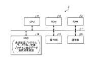
図2は、RISサーバ装置2のハードウェア構成図である。この図2に示すように、RISサーバ装置2は、CPU(Central Processing Unit)11、ROM(Read Only Memory)12、RAM(Random Access Memory)13、HDD(Hard Disk Drive)14、操作部15及び通信部16を有している。これら各部11〜16は、バスライン17を介して相互に接続されている。(Hardware configuration of RIS server device)
FIG. 2 is a hardware configuration diagram of the
HDD14(又はROM12等の他の記憶部でもよい)には、配信サーバ装置3との通信確認を行うための通信確認プログラムが記憶されている。また、HDD14には、後述するワークフロー定義、プラグイン設定データ及びワークフローテスト履歴データ等が記憶される。CPU11は、定期的又は不定期的に通信確認プログラムを実行することで、配信先サーバ装置3との通信接続の可否の判断を行い、この判断結果を、通信部16を介してMFP1に通知制御する。 A communication confirmation program for confirming communication with the
(MFPのハードウェア構成)
図3は、MFP1のハードウェア構成図である。この図3に示すように、MFP1は、CPU21、ROM22、RAM23、画像形成処理部24、HDD25、操作部26及び通信部27を有している。これら各部21〜27は、バスライン28を介して相互に接続されている。(Hardware configuration of MFP)
FIG. 3 is a hardware configuration diagram of MFP1. As shown in FIG. 3, the MFP 1 includes a CPU 21, a ROM 22, a
画像形成処理部24としては、画像読取機構及び画像印刷機構等の画像形成機構である。CPU21は、この画像形成機構を制御することで、コピー機能及びスキャナ機能等の画像印刷機能を実現する。HDD25には、サーバ判断プログラム、各RSIサーバ装置2から取得した、配信先サーバ装置3との間の通信可否を示す通信結果情報、及び、ワークフロー設定データ等が記憶されている。CPU21は、サーバ判断プログラムに基づいて動作することで、通信結果情報に基づいて選択されたRSIサーバ装置2に対して、フェールオーバを行う。 The image forming
(RSIサーバ装置の機能)
図4は、RSIサーバ装置2のCPU11が、HDD14に記憶されている通信確認プログラムを実行することで実現される各機能を示す機能ブロック図である。CPU11は通信確認プログラムを実行することで、図4に示すように、表示制御部31、ジョブ制御部32(処理データ実行部の一例)、フロー制御部33、記憶制御部34.通信制御部35、実行間隔制御部36、テストワークフロー作成部37(作成部の一例)、テスト実行ジョブ作成部38及びテスト実行部39の各機能を実現する。これら各機能の動作は、図6のフローチャートを用いて後述する。(Function of RSI server device)
FIG. 4 is a functional block diagram showing each function realized by the CPU 11 of the
(MFPの機能)
図5は、MFP1のCPU21が、HDD25に記憶されているサーバ判断プログラムを実行することで実現される各機能を示す機能ブロック図である。CPU21はサーバ判断プログラムを実行することで、図5に示すように、通信制御部41、記憶制御部42及び送信先判断部43の各機能を実現する。これら各機能の動作は、図7のフローチャートを用いて後述する。(Function of MFP)
FIG. 5 is a functional block diagram showing each function realized by the CPU 21 of the MFP 1 executing the server determination program stored in the
なお、この例では、「表示制御部31〜テスト実行部39」及び「通信制御部41〜送信先判断部43」は、それぞれソフトウェアで実現することとしたが、これらのうち、一部又は全部を、IC(Integrated Circuit)等のハードウェアで実現してもよい。 In this example, "display control unit 31 to test
また、通信確認プログラム及びサーバ判断プログラムは、インストール可能な形式または実行可能な形式のファイルでCD−ROM、フレキシブルディスク(FD)等のコンピュータ装置で読み取り可能な記録媒体に記録して提供してもよい。また、通信確認プログラム及びサーバ判断プログラムは、CD−R、DVD(Digital Versatile Disk)、ブルーレイディスク(登録商標)、半導体メモリ等のコンピュータ装置で読み取り可能な記録媒体に記録して提供してもよい。また、通信確認プログラム及びサーバ判断プログラムは、インターネット等のネットワーク経由でインストールするかたちで提供してもよいし、機器内のROM等に予め組み込んで提供してもよい。 Further, the communication confirmation program and the server judgment program may be provided by recording the files in an installable format or an executable format on a recording medium readable by a computer device such as a CD-ROM or a flexible disk (FD). Good. Further, the communication confirmation program and the server determination program may be provided by recording on a recording medium readable by a computer device such as a CD-R, a DVD (Digital Versatile Disk), a Blu-ray disc (registered trademark), or a semiconductor memory. .. Further, the communication confirmation program and the server determination program may be provided in the form of being installed via a network such as the Internet, or may be provided by being incorporated in advance in a ROM or the like in the device.
(通信確認動作)
図6は、各RSIサーバ装置2が、配信先サーバ装置3に対して定期的(又は不定期的)に行う通信確認動作の流れを示すフローチャートである。このフローチャートは、RSIサーバ装置2のCPU11がHDD14に記憶されている通信確認プログラムを読み込むことで処理がスタートとなり、図4に示すCPU11の各部31〜39により、ステップS1から順に処理が実行される。(Communication confirmation operation)
FIG. 6 is a flowchart showing a flow of a communication confirmation operation that each
まず、一例ではあるが、この実施の形態の処理実行システムの場合、表示制御部31により表示部に表示制御されるユーザインタフェースを介して、ユーザが、通信確認動作を行う間隔を設定する。ステップS1では、実行間隔制御部36が、この設定された間隔に基づいて、現在時刻が、配信先サーバ装置3に対して通信確認を行う時刻となったか否かを判別する。実行間隔制御部36により、配信先サーバ装置3に対して通信確認を行う時刻となったものと判別された際に(ステップS1:Yes)、処理がステップS2に進む。 First, as an example, in the case of the processing execution system of this embodiment, the interval at which the user performs the communication confirmation operation is set via the user interface whose display is controlled by the display unit 31. In step S1, the execution interval control unit 36 determines whether or not the current time is the time for confirming communication with the delivery
ステップS2では、テストワークフロー作成部37が、例えば入出力方式又は変換方式毎にプラグイン化されたプラグインプログラムを組み合わせて所定のワークフローのワークフロー定義を作成する。なお、この例では、テストワークフロー作成部37がワークフロー定義を作成することとして説明を進めるが、管理者等により事前に作成され記憶部に記憶されているワークフロー定義を読み出して用いてもよい。 In step S2, the test workflow creation unit 37 creates a workflow definition of a predetermined workflow by combining plug-in programs plugged in for each input / output method or conversion method, for example. In this example, the test workflow creation unit 37 creates the workflow definition, but the workflow definition created in advance by the administrator or the like and stored in the storage unit may be read and used.
また、ステップS3では、テスト実行ジョブ作成部38が、ステップS2で作成されたワークフローを実行するためのジョブデータを作成する。フロー制御部33は、作成されたフロー定義に沿ってジョブデータを制御する。 Further, in step S3, the test execution
ステップS4では、ジョブ制御部32がジョブデータを取得し、テスト実行部39を介してジョブデータのテスト実行制御(配信及び変換処理)を行うことで、変換処理したジョブデータを配信先サーバ装置3に送信する(ステップS5)。ジョブ制御部32は、配信先サーバ装置3との通信結果をパラメータ化して「ワークフローテスト履歴データ(通信結果履歴データ)」を形成する。記憶制御部34は、この通信結果履歴データをHDD14等の記憶部に記憶する(ステップS6)。ジョブ制御部32及びテスト実行部39は、通信確認部の一例である。 In step S4, the
次に、MFP1側では、例えば現在、通信に用いているRISサーバ装置2が故障等によりサーバダウンした場合、冗長化され待機状態となっている他のRISサーバ装置2に切り替えるフェールオーバを行う。この際、MFP1は、各RISサーバ装置2から上述の配信先サーバ装置3に対する通信状態を示す通信結果履歴データを取得し、配信先サーバ装置3に対して通信可能となっているRISサーバ装置2を選択してフェールオーバを行う。 Next, on the MFP1 side, for example, when the
ステップS7では、通信制御部35が、MFP1から、配信先サーバ装置3に対する通信結果履歴データの送信要求(接続確認)を受信したか否かを判別する。MFP1から通信結果履歴データの送信要求を受信しない場合(ステップS7:No)、処理がステップS1に戻り、上述のように所定の時間毎に配信先サーバ装置3に対する通信確認が行われる。 In step S7, the
これに対して、MFP1から通信結果履歴データの送信要求を受信した場合(ステップS7:Yes)、ステップS8において、記憶制御部34がHDD14から通信結果履歴データを読み出す。そして、ステップS8において、通信制御部42が、読み出された通信結果履歴データをMFP1に送信するように通信部16を通信制御する。通信制御部42は、確認結果送信制御部の一例である。 On the other hand, when the transmission request of the communication result history data is received from the MFP 1 (step S7: Yes), the storage control unit 34 reads the communication result history data from the
RISサーバ装置2は、このようなステップS1〜ステップS8の処理を、定期的又は不定的に繰り返し実行する。 The
(フェールオーバ動作)
次に、図5に示すフローチャートを用いて、RISサーバ装置2から受信した通信結果履歴データに基づいてMFP1側で行われるフェールオーバ動作を説明する。このフローチャートは、MFP1のCPU21がHDD25に記憶されているサーバ判断プログラムを読み込むことで処理がスタートとなり、図5に示すCPU11の各部41〜43により、ステップS11から順に処理が実行される。(Failover operation)
Next, the failover operation performed on the MFP1 side based on the communication result history data received from the
ステップS11では、通信制御部41が、例えば現在、通信に用いているRISサーバ装置2が故障等によりサーバダウンした場合に、冗長化され待機状態となっている他のRISサーバ装置2と配信先サーバ装置3との間の通信状態を示す通信結果履歴データの取得要求(接続確認要求)を各RISサーバ装置2に対して行う。このMFP1からの取得要求に対応して、各RISサーバ装置2は、ステップS8で説明したように、通信結果履歴データ(通信結果)をMFP1に送信する。 In step S11, when the communication control unit 41 goes down due to a failure of the
ステップS12では、通信制御部41が、各RISサーバ装置2から受信した通信結果履歴データ(通信結果)を受信する。記憶制御部42は、各通信結果履歴データ(通信結果)を、例えばHDD25等の記憶部に記憶制御する。 In step S12, the communication control unit 41 receives the communication result history data (communication result) received from each
次に、ステップS13では、送信先判断部43が、各RISサーバ装置2から受信した通信結果履歴データ(通信結果)に基づいて、配信先サーバ装置3との間の通信が可能となっているRISサーバ装置2を選択する(送信先のRISサーバ装置2として判断)。 Next, in step S13, the transmission destination determination unit 43 can communicate with the distribution
次に、ステップS14では、通信制御部41が、配信先サーバ装置3との間の通信が可能となっているRISサーバ装置2(選択したRISサーバ装置2)に対してフェールオーバを行い、ジョブデータを送信する。これにより、図7のフローチャートの処理が終了する。フェールオーバにより稼働状態となったRISサーバ装置2の通信制御部35は、情報送信制御部の一例として動作し、MFP1から受信した情報を配信先サーバ装置3に送信するように通信部16を送信制御する。 Next, in step S14, the communication control unit 41 fails over to the RIS server device 2 (selected RIS server device 2) capable of communicating with the delivery
このように、1次的なサーバ装置である各RISサーバ装置2において、2次的なサーバ装置である配信先サーバ装置3との間の通信状態を検出して、MFP1に送信する。MFP1側では、各RISサーバ装置2から受信した通信結果履歴データ(通信結果)に基づいて、配信先サーバ装置3との間の通信が可能となっているRISサーバ装置2を選択してフェールオーバを行う。これにより、フェールオーバの際に、配信先サーバ装置3でジョブデータの処理を可能とするRISサーバ装置2を選択でき、ジョブデータの処理を配信先サーバ装置3で完了させることができる。 In this way, each
(フェールオーバシーケンス)
次に、図8は、フェールオーバ時における、MFP1、RISサーバ装置2及び配信サーバ装置3の各間の通信の流れを示すシーケンス図である。この図8では、理解を容易とするために、RISサーバ装置2の処理を示すステップにおいて、図6のフローチャートの処理と同じ処理となるステップには、図8のシーケンス図でも同じステップ番号を付してある。同様に、MFP1の処理を示すステップにおいて、図7のフローチャートの処理と同じ処理となるステップには、図8のシーケンス図でも同じステップ番号を付してある。(Failover sequence)
Next, FIG. 8 is a sequence diagram showing a communication flow between the MFP 1, the
すなわち、図8のシーケンス図において、RISサーバ装置2は、定期的又は不定期的に配信先サーバ装置3との間の通信状態を確認し(ステップS1〜ステップS5)、この通信結果(通信結果履歴データ)を記憶部に記憶する(ステップS6)。 That is, in the sequence diagram of FIG. 8, the
MFP1は、フェールオーバを行う際に、各RISサーバ装置2に対して、通信結果履歴データの送信要求(接続確認要求)を行う(ステップS11)。各RISサーバ装置2は、この接続確認要求に応じて、通信結果履歴データ(通信結果)をMFP1に送信する(ステップS8、ステップS12)。 When performing a failover, the MFP 1 makes a communication result history data transmission request (connection confirmation request) to each RIS server device 2 (step S11). Each
MFP1は、各RISサーバ装置2から受信した通信結果履歴データ(通信結果)に基づいて、フェールオーバを行うRISサーバ装置2を判断する(送信先判断:ステップS13)。そして、MFP1は、判断結果となるRISサーバ装置2に対して、ジョブデータを送信する(ステップS14)。これにより、フェールオーバしたRISサーバ装置2を介して、ジョブデータを配信先サーバ装置3で処理可能とすることができる。 The MFP 1 determines the
(実施の形態の効果)
以上の説明から明らかなように、実施の形態の処理実行システムは、1次的なサーバ装置である各RISサーバ装置2において、2次的なサーバ装置である配信先サーバ装置3との間の通信状態を検出して、MFP1に送信する。MFP1側では、各RISサーバ装置2から受信した通信結果履歴データ(通信結果)に基づいて、配信先サーバ装置3との間の通信が可能となっているRISサーバ装置2を選択してフェールオーバを行う。これにより、フェールオーバの際に、配信先サーバ装置3でジョブデータの処理を可能とするRISサーバ装置2を選択でき、ジョブデータの処理を配信先サーバ装置3で完了させることができる。(Effect of embodiment)
As is clear from the above description, the processing execution system of the embodiment is between the
最後に、上述の実施の形態は、一例として提示したものであり、本発明の範囲を限定することは意図していない。この新規な実施の形態は、その他の様々な形態で実施されることが可能であり、発明の要旨を逸脱しない範囲で、種々の省略、置き換え、変更を行うことも可能である。また、実施の形態及び各実施の形態の変形は、発明の範囲や要旨に含まれると共に、特許請求の範囲に記載された発明とその均等の範囲に含まれるものである。 Finally, the embodiments described above are presented as an example and are not intended to limit the scope of the invention. This novel embodiment can be implemented in various other forms, and various omissions, replacements, and changes can be made without departing from the gist of the invention. Moreover, the embodiment and the modification of each embodiment are included in the scope and gist of the invention, and are included in the scope of the invention described in the claims and the equivalent scope thereof.
1 MFP
2 RISサーバ装置
3 配信先サーバ装置
4 ネットワーク
11 CPU
14 HDD
21 CPU
25 HDD
31 表示制御部
32 ジョブ制御部
33 フロー制御部
34 記憶制御部
35 通信制御部
36 実行間隔制御部
37 テストワークフロー作成部
38 テスト実行ジョブ作成部
39 テスト実行部
41 通信制御部
42 記憶制御部
43 送信先判断部1 MFP
2
14 HDD
21 CPU
25 HDD
31
Claims (5)
Translated fromJapanese前記情報処理サーバ装置に対する通信の可否を示す確認結果を、前記機器に送信するように前記通信部を送信制御する確認結果送信制御部と、
前記確認結果に基づいて前記機器に選択されることで稼働状態とされた際に、前記機器から受信した情報を前記情報処理サーバ装置に送信するように前記通信部を送信制御する情報送信制御部と
を有する処理実行装置。A communication confirmation unit that confirms whether or not communication is possible with the information processing server device that processes information from the device in the standby state via the communication unit.
A confirmation result transmission control unit that controls transmission of the communication unit so as to transmit a confirmation result indicating whether or not communication is possible to the information processing server device to the device.
An information transmission control unit that controls transmission of the communication unit so as to transmit information received from the equipment to the information processing server device when the device is selected based on the confirmation result and is put into an operating state. A processing execution device having and.
所定のテスト処理データを作成する作成部と、
前記テスト処理データに対応する処理を実行する処理データ実行部と、
処理後の前記テスト処理データを前記情報処理サーバ装置に送信するように前記通信部を制御する通信制御部と、を備えること
を特徴とする請求項1に記載の処理実行装置。The communication confirmation unit
A creation unit that creates predetermined test processing data, and
A processing data execution unit that executes processing corresponding to the test processing data, and
The processing execution device according to claim 1, further comprising a communication control unit that controls the communication unit so as to transmit the test processing data after processing to the information processing server device.
前記処理実行装置を介して受信した情報に対して所定の情報処理を施す情報処理サーバ装置と、
稼働中の前記処理実行装置が停止した際に、待機中の前記処理実行装置から受信した前記確認結果に基づいて、前記情報処理サーバ装置に対して通信可能な処理実行装置を選択し、選択した処理実行装置に、前記情報処理サーバ装置で処理する情報を送信する機器と
を有する処理実行システム。The processing execution device according to claim 1 or 2 is provided, and the processing execution device is provided.
An information processing server device that performs predetermined information processing on information received via the processing execution device, and
When the operating processing execution device is stopped, a processing execution device capable of communicating with the information processing server device is selected and selected based on the confirmation result received from the standby processing execution device. A processing execution system having a processing execution device having a device for transmitting information to be processed by the information processing server device.
確認結果送信制御部が、前記情報処理サーバ装置に対する通信の可否を示す確認結果を、前記機器に送信するように前記通信部を送信制御する確認結果送信制御ステップと、
情報送信制御部が、前記確認結果に基づいて前記機器に選択されることで稼働状態とされた際に、前記機器から受信した情報を前記情報処理サーバ装置に送信するように前記通信部を送信制御する情報送信制御ステップと
を有する処理実行方法。In the standby state, the communication confirmation step confirms whether or not communication is possible with the information processing server device that processes information from the device through the communication unit.
A confirmation result transmission control step in which the confirmation result transmission control unit controls transmission of the communication unit so as to transmit a confirmation result indicating whether or not communication with the information processing server device is possible to the device.
When the information transmission control unit is selected by the device based on the confirmation result and is put into an operating state, the communication unit is transmitted so as to transmit the information received from the device to the information processing server device. A process execution method having an information transmission control step to be controlled.
待機状態時において、機器からの情報の情報処理を行う情報処理サーバ装置に対する通信の可否を、通信部を介して確認する通信確認部と、
前記情報処理サーバ装置に対する通信の可否を示す確認結果を、前記機器に送信するように前記通信部を送信制御する確認結果送信制御部と、
前記確認結果に基づいて前記機器に選択されることで稼働状態とされた際に、前記機器から受信した情報を前記情報処理サーバ装置に送信するように前記通信部を送信制御する情報送信制御部として機能させること
を特徴とする処理実行プログラム。Computer,
A communication confirmation unit that confirms whether or not communication is possible with the information processing server device that processes information from the device in the standby state via the communication unit.
A confirmation result transmission control unit that controls transmission of the communication unit so as to transmit a confirmation result indicating whether or not communication is possible to the information processing server device to the device.
An information transmission control unit that controls transmission of the communication unit so as to transmit information received from the equipment to the information processing server device when the device is selected based on the confirmation result and is put into an operating state. A processing execution program characterized by functioning as.
Priority Applications (1)
| Application Number | Priority Date | Filing Date | Title |
|---|---|---|---|
| JP2019196653AJP2021071798A (en) | 2019-10-29 | 2019-10-29 | Processing execution device, processing execution system, processing execution method and processing execution program |
Applications Claiming Priority (1)
| Application Number | Priority Date | Filing Date | Title |
|---|---|---|---|
| JP2019196653AJP2021071798A (en) | 2019-10-29 | 2019-10-29 | Processing execution device, processing execution system, processing execution method and processing execution program |
Publications (1)
| Publication Number | Publication Date |
|---|---|
| JP2021071798Atrue JP2021071798A (en) | 2021-05-06 |
Family
ID=75713114
Family Applications (1)
| Application Number | Title | Priority Date | Filing Date |
|---|---|---|---|
| JP2019196653APendingJP2021071798A (en) | 2019-10-29 | 2019-10-29 | Processing execution device, processing execution system, processing execution method and processing execution program |
Country Status (1)
| Country | Link |
|---|---|
| JP (1) | JP2021071798A (en) |
Cited By (1)
| Publication number | Priority date | Publication date | Assignee | Title |
|---|---|---|---|---|
| US12175784B2 (en) | 2021-03-22 | 2024-12-24 | Ricoh Company, Ltd. | Information processing apparatus, information processing system, and information processing method |
- 2019
- 2019-10-29JPJP2019196653Apatent/JP2021071798A/enactivePending
Cited By (1)
| Publication number | Priority date | Publication date | Assignee | Title |
|---|---|---|---|---|
| US12175784B2 (en) | 2021-03-22 | 2024-12-24 | Ricoh Company, Ltd. | Information processing apparatus, information processing system, and information processing method |
Similar Documents
| Publication | Publication Date | Title |
|---|---|---|
| US20240040050A1 (en) | Information processing apparatus, method of controlling the same, and storage medium for setting a naming rule for a file name | |
| US8705084B2 (en) | Image processing system, image processing apparatus and method for controlling the same | |
| US9298400B2 (en) | Communication system, image processing apparatus, control method for image processing apparatus, and storage medium | |
| US11182118B2 (en) | Image forming apparatus, control method for the same, image forming system and storage medium | |
| US20160063508A1 (en) | Communication system, image processing apparatus, method for controlling image processing apparatus, and storage medium | |
| US20210286570A1 (en) | Information processing apparatus, control method therefor and storage medium | |
| US20200104085A1 (en) | Printing apparatus, control method, and storage medium thereof | |
| US10999474B2 (en) | Electronic device, control method of electronic device, information processing system, and storage medium | |
| US12225097B2 (en) | Monitoring device, network device, control method of monitoring device, control method of network device, and recording medium | |
| US10194048B2 (en) | Image communication apparatus, method of controlling same, and storage medium for displaying addresses from address book | |
| JP2021071798A (en) | Processing execution device, processing execution system, processing execution method and processing execution program | |
| EP4303712A1 (en) | Printing apparatus, control method, and program | |
| US12073133B2 (en) | System and method for providing printing service and configured to change printer connection destination | |
| JP6368157B2 (en) | Communication system and control method thereof | |
| US9250841B2 (en) | Print server, control method of print server, and storage medium | |
| US10592174B2 (en) | Information processing system, server and non-transitory computer-readable recording medium encoded with data distribution program | |
| US11474760B2 (en) | Information processing system, server, and information processing method which prints using guest account information | |
| US20250071226A1 (en) | Printing device, control method, and medium | |
| US12052151B2 (en) | Network device and method for controlling the same | |
| US12169654B2 (en) | System and method for providing printing service | |
| US20250077151A1 (en) | Information processing device, method for controlling the same, and printing system | |
| US20230291844A1 (en) | Information processing apparatus, non-transitory computer readable medium storing program, and information processing method | |
| US20250117168A1 (en) | Relay device having proxy server function, control method thereof, and recording medium | |
| US9531904B2 (en) | Information processing apparatus, control method of information processing apparatus, and recording medium | |
| JP6439955B2 (en) | Pull print system |