JP2021065943A - Robot system - Google Patents
Robot systemDownload PDFInfo
- Publication number
- JP2021065943A JP2021065943AJP2019190767AJP2019190767AJP2021065943AJP 2021065943 AJP2021065943 AJP 2021065943AJP 2019190767 AJP2019190767 AJP 2019190767AJP 2019190767 AJP2019190767 AJP 2019190767AJP 2021065943 AJP2021065943 AJP 2021065943A
- Authority
- JP
- Japan
- Prior art keywords
- robot
- axis
- motor
- external force
- control device
- Prior art date
- Legal status (The legal status is an assumption and is not a legal conclusion. Google has not performed a legal analysis and makes no representation as to the accuracy of the status listed.)
- Granted
Links
- 210000000707wristAnatomy0.000description7
- 238000010586diagramMethods0.000description2
- 238000000034methodMethods0.000description1
Images


Classifications
- B—PERFORMING OPERATIONS; TRANSPORTING
- B25—HAND TOOLS; PORTABLE POWER-DRIVEN TOOLS; MANIPULATORS
- B25J—MANIPULATORS; CHAMBERS PROVIDED WITH MANIPULATION DEVICES
- B25J9/00—Programme-controlled manipulators
- B25J9/16—Programme controls
- B25J9/1628—Programme controls characterised by the control loop
- B25J9/1633—Programme controls characterised by the control loop compliant, force, torque control, e.g. combined with position control
- B—PERFORMING OPERATIONS; TRANSPORTING
- B25—HAND TOOLS; PORTABLE POWER-DRIVEN TOOLS; MANIPULATORS
- B25J—MANIPULATORS; CHAMBERS PROVIDED WITH MANIPULATION DEVICES
- B25J13/00—Controls for manipulators
- B25J13/08—Controls for manipulators by means of sensing devices, e.g. viewing or touching devices
- B25J13/085—Force or torque sensors
- B—PERFORMING OPERATIONS; TRANSPORTING
- B25—HAND TOOLS; PORTABLE POWER-DRIVEN TOOLS; MANIPULATORS
- B25J—MANIPULATORS; CHAMBERS PROVIDED WITH MANIPULATION DEVICES
- B25J9/00—Programme-controlled manipulators
- B25J9/02—Programme-controlled manipulators characterised by movement of the arms, e.g. cartesian coordinate type
- B25J9/04—Programme-controlled manipulators characterised by movement of the arms, e.g. cartesian coordinate type by rotating at least one arm, excluding the head movement itself, e.g. cylindrical coordinate type or polar coordinate type
- B25J9/041—Cylindrical coordinate type
- B25J9/042—Cylindrical coordinate type comprising an articulated arm
- B—PERFORMING OPERATIONS; TRANSPORTING
- B25—HAND TOOLS; PORTABLE POWER-DRIVEN TOOLS; MANIPULATORS
- B25J—MANIPULATORS; CHAMBERS PROVIDED WITH MANIPULATION DEVICES
- B25J9/00—Programme-controlled manipulators
- B25J9/16—Programme controls
- B25J9/1602—Programme controls characterised by the control system, structure, architecture
- B25J9/1607—Calculation of inertia, jacobian matrixes and inverses
Landscapes
- Engineering & Computer Science (AREA)
- Robotics (AREA)
- Mechanical Engineering (AREA)
- Physics & Mathematics (AREA)
- Mathematical Physics (AREA)
- Automation & Control Theory (AREA)
- Human Computer Interaction (AREA)
- Manipulator (AREA)
Abstract
Description
Translated fromJapanese本発明は、ロボットシステムに関するものである。 The present invention relates to a robot system.
ロボットの教示方法として、作業者がロボットを直接手で押して操作しながら教示を行うリードスルー教示(直接教示)が知られている(例えば、特許文献1参照。)。
特許文献1のロボットは、モータ電流に基づいて作業者がロボットに加えた外力トルクを算出し、算出された外力トルクに基づいて外力トルクが零となるようにモータを制御する。As a method of teaching a robot, there is known a lead-through teaching (direct teaching) in which an operator directly pushes the robot by hand to perform teaching (see, for example, Patent Document 1).
The robot of Patent Document 1 calculates the external force torque applied to the robot by the operator based on the motor current, and controls the motor so that the external force torque becomes zero based on the calculated external force torque.
リードスルー教示において、作業者の負担を軽減するには、作業者がロボットに加える外力を小さくすることが望ましい。しかしながら、作業者がロボットに加える外力トルクが同じでも、作業者がロボットに加える外力はロボットの姿勢によって相違する。すなわち、回転させようとする軸に近接した位置において外力を加える場合には、軸から離れた位置において外力を加える場合よりも大きな外力を加えなければ、同じ外力トルクが得られない。したがって、作業者が、回転させようとする軸に近接した位置においてロボットに外力を加えなければならない場合においても大きな外力を加えずにリードスルー教示を行うことができることが望ましい。 In the lead-through teaching, in order to reduce the burden on the operator, it is desirable to reduce the external force applied to the robot by the operator. However, even if the external force torque applied to the robot by the operator is the same, the external force applied to the robot by the operator differs depending on the posture of the robot. That is, when an external force is applied at a position close to the shaft to be rotated, the same external force torque cannot be obtained unless a larger external force is applied than when an external force is applied at a position away from the shaft. Therefore, it is desirable that the operator can perform lead-through teaching without applying a large external force even when an external force must be applied to the robot at a position close to the axis to be rotated.
本発明の一態様は、モータにより軸線回りに回転駆動される1以上の回転関節を備えるロボットと、各該回転関節に作用する前記軸線回りの外力トルクに基づいて、前記モータを制御する制御装置とを備え、前記ロボットに、外力を加える力点が予め設定され、前記制御装置は、前記ロボットの前記回転関節の角度に基づいて、1以上の前記回転関節の前記軸線からの前記力点までの距離を算出し、算出された前記距離が短いほど前記モータに対する操作量を大きく調節するロボットシステムである。 One aspect of the present invention is a robot having one or more rotary joints that are rotationally driven around an axis by a motor, and a control device that controls the motor based on an external force torque around the axis that acts on each of the rotary joints. A force point for applying an external force to the robot is preset, and the control device is a distance from the axis of one or more of the rotary joints to the force point based on the angle of the rotary joint of the robot. Is calculated, and the shorter the calculated distance is, the larger the amount of operation with respect to the motor is adjusted.
本発明の一実施形態に係るロボットシステム1について、図面を参照して以下に説明する。
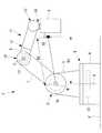
本実施形態に係るロボットシステム1は、図1に示されるように、ロボット2と制御装置3とを備えている。The robot system 1 according to the embodiment of the present invention will be described below with reference to the drawings.
As shown in FIG. 1, the robot system 1 according to the present embodiment includes a
ロボット2は、例えば、6個の回転関節を備える垂直多関節型ロボットであり、鉛直な第1軸線(鉛直軸線、軸線)A回りに床面Fに設置されるベース4に対して回転可能に支持された旋回胴5を備える第1回転関節(回転関節、第1軸)6を備えている。また、ロボット2は、水平な第2軸線(水平軸線、軸線)B回りに旋回胴5に対して回転可能に支持された第1アーム(アーム)7を備える第2回転関節(回転関節、第2軸)8を備えている。 The
また、ロボット2は、水平な第3軸線(軸線)C回りに第1アーム7に対して回転可能に支持された第2アーム9を備える第3回転関節(回転関節)10を備えている。さらに、ロボット2は、第2アーム9の先端に手首ユニット11を備えている。手首ユニット11は3つの回転関節12,13,14を備えている。 Further, the
ロボット2は、例えば、第1回転関節6のベース4と旋回胴5との間、第2回転関節8の旋回胴5と第1アーム7との間および第1アーム7と第2アーム8との間に、両者間に加わる外力トルクを検出するトルクセンサ15,16,17をそれぞれ備えている。
また、ロボット2には、手首ユニット11の先端近傍に作業者が把持して外力を加えるハンドル(力点)18を備えるツールSが装着されている。The
Further, the
制御装置3は、図2に示されるように、作業者がツールSのハンドル18に外力を加えることによりトルクセンサ15,16,17により外力トルクが検出されると、検出された外力トルクに応じて、各回転関節6,8,10,12,13,14のモータ(図示略)を制御するモータ制御部22を備えている。
具体的には、制御装置3は、外力トルクが作用すると、トルクセンサ15,16,17により検出される外力トルクを低減する方向に各回転関節6,8,10,12,13,14のモータを駆動する。As shown in FIG. 2, the
Specifically, the
本実施形態においては、制御装置3は、ロボット2の手首ユニット11の先端に装着するツールSの形状を記憶する記憶部19を備えている。また、制御装置3は、各回転関節6,8,10,12,13,14のモータに備えられたエンコーダ20からの角度情報および記憶部19に記憶されているツールSの形状の情報を受信して、第1軸線Aおよび第2軸線Bからハンドル18までの距離を逐次算出する距離算出部21を備えている。 In the present embodiment, the
そして、モータ制御部22は、例えば、図3に示されるように、算出された距離が大きくなるほどモータに対する操作量を小さくする。
例えば、図4に示されるように、第1アーム7および第2アーム9が折り畳まれる場合には、ツールSのハンドル18と第1軸線Aおよび第2軸線Bとの距離D1,D2は小さくなる。一方、図5に示されるように、第1アーム7および第2アーム9が伸長する場合には、ツールSのハンドル18が第1軸線Aおよび第2軸線Bから離れた位置に配置される。Then, for example, as shown in FIG. 3, the
For example, as shown in FIG. 4, when the
これらの場合にハンドル18に加える外力とトルクとの関係は、ハンドル18が軸線A,Bに近いほどトルクセンサ15,16により検出される外力トルクは小さくなる。したがって、モータにより発生するトルクを外力トルクのみに基づいて発生させる場合には、ハンドル18が軸線A,Bに近いほど作業者が大きな外力を加えない限り必要なトルクをモータに発生させることができず、作業者にかかる負担が大きい。 Regarding the relationship between the external force applied to the
本実施形態に係るロボットシステム1によれば、トルクセンサ15,16により検出されるトルクの大きさに基づいてモータの操作量を設定することに加え、ハンドル18の軸線A,Bからの距離D1,D2が小さいほどモータに指令する操作量を増大させる。これにより、ハンドル18の軸線A,Bからの距離D1,D2に関わらず、必要なトルクをモータに発生させるために作業者がハンドル18に加える外力を略同等にすることができる。 According to the robot system 1 according to the present embodiment, in addition to setting the operation amount of the motor based on the magnitude of the torque detected by the
その結果、ハンドル18が軸線A,Bに近い位置に配置されている場合に、作業者が大きな外力を加えなくてもロボット2を動作させることができ、リードスルー教示を行う際に作業者にかかる負担を軽減することができるという利点がある。また、リードスルー教示を行う上で、ハンドル18の位置に関わらず、作業者が加える外力がほぼ同等であれば、リードスルー教示の操作性を向上することができる。 As a result, when the
なお、本実施形態においては、制御装置3が、ハンドル18と軸線A,Bとの距離D1,D2に応じてモータの操作量を増大させることとした。これに代えて、制御装置3は、ロボット2の各部の形状および重量、および、手首ユニット11の先端に装着されたツールSの形状および重量に基づいてロボット2およびツールSの実際の慣性量を算出し、算出された慣性量が小さいほどモータの操作量を大きくしてもよい。 In the present embodiment, the
また、本実施形態においては、ツールSに備えられたハンドル18に力点を設定し、距離算出部21が、第1軸線Aおよび第2軸線Bからハンドル18までの距離D1,D2を算出したが、これに限定されるものではない。距離算出部21は、作業者が物理的に外力を加えることができる軸線A,Bから最も離れた点までの距離を算出してもよいし、例えば、手首ユニット11の先端点、あるいは、手首ユニット11の中心を力点として想定し、それらの位置までの距離を算出してもよい。 Further, in the present embodiment, the emphasis point is set on the
また、本実施形態においては、ハンドル18から第1軸線Aおよび第2軸線Bまでの距離D1,D2を算出したが、これに代えて、他の回転関節10,12,13,14の軸線までの距離を算出し、距離が小さいほど各回転関節10,12,13,14のモータへの操作量を大きくする制御を行ってもよい。 Further, in the present embodiment, the distances D1 and D2 from the
また、本実施形態においては、各軸線A,Bからハンドル18までの距離D1,D2が大きくなるほど、モータの操作量をリニアに小さくすることとしたが、これに代えて、図6に示されるように、任意の曲線に沿って小さくすることにしてもよい。
また、6軸多関節型ロボットを例示して説明したが、ロボット2の形態はこれに限定されるものではない。Further, in the present embodiment, the operating amount of the motor is linearly reduced as the distances D1 and D2 from the axes A and B to the
Further, although the 6-axis articulated robot has been described as an example, the form of the
1 ロボットシステム
2 ロボット
3 制御装置
4 ベース
5 旋回胴
6 第1回転関節(回転関節、第1軸)
7 第1アーム(アーム)
8 第2回転関節(回転関節、第2軸)
10 第3回転関節(回転関節)
12,13,14 回転関節
18 ハンドル(力点)
A 第1軸線(鉛直軸線、軸線)
B 第2軸線(水平軸線、軸線)
C 第3軸線(軸線)
F 床面1
7 1st arm (arm)
8 2nd rotary joint (rotary joint, 2nd axis)
10 Third rotary joint (rotary joint)
12, 13, 14
A 1st axis (vertical axis, axis)
B 2nd axis (horizontal axis, axis)
C 3rd axis (axis)
F floor
Claims (3)
Translated fromJapanese各該回転関節に作用する前記軸線回りの外力トルクに基づいて、前記モータを制御する制御装置とを備え、
前記ロボットに、外力を加える力点が予め設定され、
前記制御装置は、前記ロボットの前記回転関節の角度に基づいて、1以上の前記回転関節の前記軸線からの前記力点までの距離を算出し、算出された前記距離が短いほど前記モータに対する操作量を大きく調節するロボットシステム。A robot equipped with one or more rotary joints that are rotationally driven around an axis by a motor,
A control device for controlling the motor based on an external force torque around the axis acting on each of the rotary joints is provided.
A force point for applying an external force to the robot is set in advance.
The control device calculates the distance from the axis of one or more of the rotary joints to the force point based on the angle of the rotary joints of the robot, and the shorter the calculated distance, the more the amount of operation with respect to the motor. A robot system that greatly adjusts.
各該回転関節に作用する前記軸線回りの外力トルクに基づいて、前記モータを制御する制御装置とを備え、
該制御装置は、前記ロボットの前記回転関節の角度に基づいて、前記ロボットの慣性量を算出し、算出された前記慣性量が小さいほど前記モータに対する操作量を大きく調節するロボットシステム。A robot equipped with one or more rotary joints that are rotationally driven around an axis by a motor,
A control device for controlling the motor based on an external force torque around the axis acting on each of the rotary joints is provided.
The control device is a robot system that calculates the amount of inertia of the robot based on the angle of the rotary joint of the robot, and adjusts the amount of operation with respect to the motor as the calculated amount of inertia is smaller.
該制御装置は、前記ロボットの前記回転関節の角度に基づいて、前記第1軸および/または前記第2軸を回転駆動する前記モータに対する前記操作量を調節する請求項1または請求項2に記載のロボットシステム。
The robot has a base installed on the floor, a first axis having a swivel cylinder that is rotationally driven with respect to the base around the vertical axis, and an arm that is rotationally driven with respect to the swivel around the horizontal axis. With a second axis
The control device according to claim 1 or 2, wherein the control device adjusts the operation amount with respect to the motor that rotationally drives the first axis and / or the second axis based on the angle of the rotary joint of the robot. Robot system.
Priority Applications (4)
| Application Number | Priority Date | Filing Date | Title |
|---|---|---|---|
| JP2019190767AJP7388870B2 (en) | 2019-10-18 | 2019-10-18 | Robot systems and control equipment |
| US17/018,345US11806874B2 (en) | 2019-10-18 | 2020-09-11 | Robot system |
| DE102020126205.1ADE102020126205A1 (en) | 2019-10-18 | 2020-10-07 | Robotic system |
| CN202011082942.0ACN112677135A (en) | 2019-10-18 | 2020-10-12 | Robot system |
Applications Claiming Priority (1)
| Application Number | Priority Date | Filing Date | Title |
|---|---|---|---|
| JP2019190767AJP7388870B2 (en) | 2019-10-18 | 2019-10-18 | Robot systems and control equipment |
Publications (2)
| Publication Number | Publication Date |
|---|---|
| JP2021065943Atrue JP2021065943A (en) | 2021-04-30 |
| JP7388870B2 JP7388870B2 (en) | 2023-11-29 |
Family
ID=75268743
Family Applications (1)
| Application Number | Title | Priority Date | Filing Date |
|---|---|---|---|
| JP2019190767AActiveJP7388870B2 (en) | 2019-10-18 | 2019-10-18 | Robot systems and control equipment |
Country Status (4)
| Country | Link |
|---|---|
| US (1) | US11806874B2 (en) |
| JP (1) | JP7388870B2 (en) |
| CN (1) | CN112677135A (en) |
| DE (1) | DE102020126205A1 (en) |
Cited By (1)
| Publication number | Priority date | Publication date | Assignee | Title |
|---|---|---|---|---|
| WO2025163746A1 (en)* | 2024-01-30 | 2025-08-07 | ファナック株式会社 | Robot control device |
Families Citing this family (2)
| Publication number | Priority date | Publication date | Assignee | Title |
|---|---|---|---|---|
| JP2024164671A (en)* | 2023-05-15 | 2024-11-27 | 株式会社不二越 | Collaborative Robot System |
| CN120677038A (en)* | 2023-07-03 | 2025-09-19 | 深圳华大智造云影医疗科技有限公司 | Robot posture processing method and device, electronic device and storage medium |
Citations (6)
| Publication number | Priority date | Publication date | Assignee | Title |
|---|---|---|---|---|
| JPH03130808A (en)* | 1989-10-17 | 1991-06-04 | Citizen Watch Co Ltd | Method and device for control of robot |
| JPH06110542A (en)* | 1992-09-28 | 1994-04-22 | Mitsubishi Heavy Ind Ltd | Auxiliary device for directly teaching manipulator |
| JPH06190750A (en)* | 1992-12-24 | 1994-07-12 | Toyoda Mach Works Ltd | Robot control device |
| JPH07261844A (en)* | 1994-03-23 | 1995-10-13 | Matsushita Electric Ind Co Ltd | Motor control device |
| JP2005293098A (en)* | 2004-03-31 | 2005-10-20 | Fanuc Ltd | Robot teaching apparatus |
| US9592608B1 (en)* | 2014-12-15 | 2017-03-14 | X Development Llc | Methods and systems for providing feedback during teach mode |
Family Cites Families (19)
| Publication number | Priority date | Publication date | Assignee | Title |
|---|---|---|---|---|
| JPS61273610A (en) | 1985-05-30 | 1986-12-03 | Matsushita Electric Ind Co Ltd | industrial robot |
| JPS63231503A (en) | 1987-03-19 | 1988-09-27 | Kawasaki Heavy Ind Ltd | Robot drive control method |
| KR20060113930A (en)* | 2003-12-30 | 2006-11-03 | 리포소닉스 인코포레이티드 | Systems and devices for the destruction of adipose tissue |
| US20060249315A1 (en)* | 2005-03-31 | 2006-11-09 | Massachusetts Institute Of Technology | Artificial human limbs and joints employing actuators, springs, and variable-damper elements |
| JP2010076074A (en)* | 2008-09-29 | 2010-04-08 | Panasonic Corp | Robot control method |
| FI20105732A0 (en)* | 2010-06-24 | 2010-06-24 | Zenrobotics Oy | Procedure for selecting physical objects in a robotic system |
| DE102011106321A1 (en)* | 2011-07-01 | 2013-01-03 | Kuka Laboratories Gmbh | Method and control means for controlling a robot |
| US9820818B2 (en)* | 2012-08-03 | 2017-11-21 | Stryker Corporation | System and method for controlling a surgical manipulator based on implant parameters |
| JPWO2014155559A1 (en)* | 2013-03-27 | 2017-02-16 | 株式会社安川電機 | Notch filter, external force estimator, motor controller and robot system |
| US9452532B2 (en)* | 2014-01-27 | 2016-09-27 | Panasonic Intellectual Property Management Co., Ltd. | Robot, device and method for controlling robot, and computer-readable non-transitory recording medium |
| JP6193816B2 (en)* | 2014-06-20 | 2017-09-06 | ファナック株式会社 | Articulated robot with arm retracting function |
| US9561829B1 (en)* | 2014-09-03 | 2017-02-07 | X Development Llc | Robotic leg with multiple robotic feet |
| US9475191B1 (en)* | 2014-09-03 | 2016-10-25 | Google Inc. | Robotic leg parallel to a ball screw |
| US9440353B1 (en)* | 2014-12-29 | 2016-09-13 | Google Inc. | Offline determination of robot behavior |
| CN204525458U (en)* | 2015-04-10 | 2015-08-05 | 苏州荣威工贸有限公司 | A kind of robot Bidirectional power module |
| JP6200456B2 (en) | 2015-06-29 | 2017-09-20 | ファナック株式会社 | Interference check system between machine tool and robot |
| CN108430375B (en)* | 2015-11-11 | 2021-05-07 | 马科外科公司 | Robotic system and method of back-driving the same |
| JP2017205835A (en) | 2016-05-18 | 2017-11-24 | 株式会社リコー | Control device of manipulator device, control method of the manipulator device, and control program of the manipulator device |
| JP2019040264A (en) | 2017-08-22 | 2019-03-14 | ファナック株式会社 | Cooperation system of machine tool and robot |
- 2019
- 2019-10-18JPJP2019190767Apatent/JP7388870B2/enactiveActive
- 2020
- 2020-09-11USUS17/018,345patent/US11806874B2/enactiveActive
- 2020-10-07DEDE102020126205.1Apatent/DE102020126205A1/enactivePending
- 2020-10-12CNCN202011082942.0Apatent/CN112677135A/enactivePending
Patent Citations (6)
| Publication number | Priority date | Publication date | Assignee | Title |
|---|---|---|---|---|
| JPH03130808A (en)* | 1989-10-17 | 1991-06-04 | Citizen Watch Co Ltd | Method and device for control of robot |
| JPH06110542A (en)* | 1992-09-28 | 1994-04-22 | Mitsubishi Heavy Ind Ltd | Auxiliary device for directly teaching manipulator |
| JPH06190750A (en)* | 1992-12-24 | 1994-07-12 | Toyoda Mach Works Ltd | Robot control device |
| JPH07261844A (en)* | 1994-03-23 | 1995-10-13 | Matsushita Electric Ind Co Ltd | Motor control device |
| JP2005293098A (en)* | 2004-03-31 | 2005-10-20 | Fanuc Ltd | Robot teaching apparatus |
| US9592608B1 (en)* | 2014-12-15 | 2017-03-14 | X Development Llc | Methods and systems for providing feedback during teach mode |
Cited By (1)
| Publication number | Priority date | Publication date | Assignee | Title |
|---|---|---|---|---|
| WO2025163746A1 (en)* | 2024-01-30 | 2025-08-07 | ファナック株式会社 | Robot control device |
Also Published As
| Publication number | Publication date |
|---|---|
| CN112677135A (en) | 2021-04-20 |
| JP7388870B2 (en) | 2023-11-29 |
| DE102020126205A1 (en) | 2021-04-22 |
| US11806874B2 (en) | 2023-11-07 |
| US20210114210A1 (en) | 2021-04-22 |
Similar Documents
| Publication | Publication Date | Title |
|---|---|---|
| JP5895628B2 (en) | ROBOT CONTROL METHOD, ROBOT CONTROL DEVICE, AND ROBOT CONTROL SYSTEM | |
| JP6584102B2 (en) | Robot apparatus, robot control method, program, recording medium, and article manufacturing method | |
| JP6238628B2 (en) | Robot device, robot control method, robot control program, and part manufacturing method using robot device | |
| US9381641B2 (en) | Robot and method of operating robot | |
| US20150127151A1 (en) | Method For Programming Movement Sequences Of A Redundant Industrial Robot And Industrial Robot | |
| JP7388870B2 (en) | Robot systems and control equipment | |
| JP6379853B2 (en) | Robot control apparatus and control method | |
| JP6717921B2 (en) | Robot operating device with handle for operating the robot | |
| US11358276B2 (en) | Robot and robot system | |
| JP2007319970A (en) | Industrial robot tool position / posture control method and control system | |
| KR20180099623A (en) | Robot arm and robot wrist | |
| JP6565752B2 (en) | Robot control apparatus and robot control method | |
| JP2015221073A (en) | Rehabilitation apparatus, control method and control program | |
| JP5703870B2 (en) | Robot control device | |
| JP2013226619A (en) | Robot control method and robot control device | |
| JP2019030931A (en) | Robot control apparatus, control method, and robot apparatus | |
| JP2013215839A (en) | Method for controlling robot having redundant degree of freedom, device for controlling robot, and system for controlling robot | |
| JP2013220501A (en) | Robot control method and robot control device | |
| JP4970492B2 (en) | Articulated robot | |
| JP4822067B2 (en) | Robot and its direct teaching device | |
| JP6444092B2 (en) | Human movement support device | |
| JP6429977B2 (en) | Robot apparatus and robot control method | |
| JP5633268B2 (en) | Robot control device | |
| JP2010036293A (en) | Multi-articulated robot | |
| JP2014159066A (en) | Robot control device and robot control method |
Legal Events
| Date | Code | Title | Description |
|---|---|---|---|
| A621 | Written request for application examination | Free format text:JAPANESE INTERMEDIATE CODE: A621 Effective date:20220720 | |
| A977 | Report on retrieval | Free format text:JAPANESE INTERMEDIATE CODE: A971007 Effective date:20230531 | |
| A131 | Notification of reasons for refusal | Free format text:JAPANESE INTERMEDIATE CODE: A131 Effective date:20230606 | |
| A521 | Request for written amendment filed | Free format text:JAPANESE INTERMEDIATE CODE: A523 Effective date:20230731 | |
| A521 | Request for written amendment filed | Free format text:JAPANESE INTERMEDIATE CODE: A523 Effective date:20230804 | |
| TRDD | Decision of grant or rejection written | ||
| A01 | Written decision to grant a patent or to grant a registration (utility model) | Free format text:JAPANESE INTERMEDIATE CODE: A01 Effective date:20231017 | |
| A61 | First payment of annual fees (during grant procedure) | Free format text:JAPANESE INTERMEDIATE CODE: A61 Effective date:20231116 | |
| R150 | Certificate of patent or registration of utility model | Ref document number:7388870 Country of ref document:JP Free format text:JAPANESE INTERMEDIATE CODE: R150 |