JP2021063930A - Fingertip capillary blood flow observation microscope - Google Patents
Fingertip capillary blood flow observation microscopeDownload PDFInfo
- Publication number
- JP2021063930A JP2021063930AJP2019189080AJP2019189080AJP2021063930AJP 2021063930 AJP2021063930 AJP 2021063930AJP 2019189080 AJP2019189080 AJP 2019189080AJP 2019189080 AJP2019189080 AJP 2019189080AJP 2021063930 AJP2021063930 AJP 2021063930A
- Authority
- JP
- Japan
- Prior art keywords
- finger
- sandwiching
- cuticle
- microscope
- blood flow
- Prior art date
- Legal status (The legal status is an assumption and is not a legal conclusion. Google has not performed a legal analysis and makes no representation as to the accuracy of the status listed.)
- Granted
Links
- 230000008822capillary blood flowEffects0.000titleclaimsabstractdescription35
- 230000017531blood circulationEffects0.000claimsabstractdescription32
- 210000000282nailAnatomy0.000claimsabstractdescription25
- 210000004905finger nailAnatomy0.000claimsabstractdescription24
- 230000003287optical effectEffects0.000claimsabstractdescription21
- 230000002441reversible effectEffects0.000claimsdescription2
- 210000002615epidermisAnatomy0.000description12
- 238000005286illuminationMethods0.000description7
- 238000003780insertionMethods0.000description5
- 230000037431insertionEffects0.000description5
- 239000000463materialSubstances0.000description5
- 238000000034methodMethods0.000description5
- 238000010586diagramMethods0.000description4
- 239000000835fiberSubstances0.000description4
- 210000000078clawAnatomy0.000description3
- 239000002184metalSubstances0.000description3
- 238000003384imaging methodMethods0.000description2
- 229910000639Spring steelInorganic materials0.000description1
- 230000001154acute effectEffects0.000description1
- 210000000988bone and boneAnatomy0.000description1
- 238000012986modificationMethods0.000description1
- 230000004048modificationEffects0.000description1
- 230000029058respiratory gaseous exchangeEffects0.000description1
- 229920002050silicone resinPolymers0.000description1
- 210000003491skinAnatomy0.000description1
Images


Landscapes
- Measuring Pulse, Heart Rate, Blood Pressure Or Blood Flow (AREA)
- Focusing (AREA)
- Microscoopes, Condenser (AREA)
- Automatic Focus Adjustment (AREA)
Abstract
Description
Translated fromJapaneseこの発明は、指先毛細血管血流観察顕微鏡に関し、特に、手の指先の毛細血管の血流を観察するのに用いて好適なものである。 The present invention relates to a fingertip capillary blood flow observation microscope, and is particularly suitable for observing blood flow in the capillaries of the fingertips of a hand.
従来、手の指先などの毛細血管の血流を観察する装置として血流観察用デジタルマイクロスコープが知られており、市販されている(非特許文献1参照。)。この血流観察用デジタルマイクロスコープは、顕微鏡(マイクロスコープ)とモニター(ディスプレイ)とを組み合わせたものである。この血流観察用デジタルマイクロスコープにより手の指先の毛細血管の血流を観察する方法は次の通りである。すなわち、まず、顕微鏡の直下の観察台に設けられた指置きに利き手の反対側の手の薬指を置く。薬指には事前に乱反射防止用オイルを塗布しておく。指置きには指の形状に合わせてU字形の溝が形成されている。そして、指置きに指を置いた状態で、顕微鏡の先端を左右前後に移動し、かつ被験者の指も動かしながら指の爪の甘皮の直ぐ後方の部分の表面に接近させる。その後、モニターを見ながら顕微鏡の鏡筒に取り付けられたピント調節ねじと被験者の指移動で皮膚直下の毛細血管の映像が出るように位置とピントを調節する。 Conventionally, a digital microscope for observing blood flow has been known as a device for observing blood flow in capillaries such as the fingertips of a hand, and is commercially available (see Non-Patent Document 1). This digital microscope for observing blood flow is a combination of a microscope (microscope) and a monitor (display). The method of observing the blood flow in the capillaries of the fingertips of the hand with this digital microscope for observing blood flow is as follows. That is, first, the ring finger of the hand opposite to the dominant hand is placed on the finger rest provided on the observation table directly under the microscope. Apply anti-diffuse oil to the ring finger in advance. A U-shaped groove is formed on the finger rest to match the shape of the finger. Then, with the finger placed on the finger rest, the tip of the microscope is moved left and right and back and forth, and the subject's finger is also moved to approach the surface of the portion immediately behind the cuticle of the fingernail. Then, while looking at the monitor, adjust the position and focus so that the image of the capillaries just below the skin appears by moving the focus adjustment screw attached to the lens barrel of the microscope and the subject's finger.
非特許文献1に記載された血流観察用デジタルマイクロスコープでは、血流を鮮明に観察することができるのは、爪の甘皮からコンマ数ミリ以内の爪根部の表皮であるため、そこに顕微鏡を位置合わせすることが重要である。しかしながら、指サイズや爪サイズの個人差が大きく、かつ観察時には指置きに指を置くだけであるため、初期位置合わせやピント合わせだけでも大変である。しかも、観察中に呼吸などにより体がぶれるため観察対象の指も上下左右に移動してしまうことからその都度位置合わせやピント合わせが必要となることにより、毛細血管の血流を鮮明に観察するためには操作に熟練が必要であった。 With the digital microscope for observing blood flow described in Non-Patent Document 1, blood flow can be clearly observed only in the epidermis of the nail root within a few millimeters from the cuticle of the nail. It is important to align. However, since individual differences in finger size and nail size are large, and only the finger is placed on the finger rest during observation, it is difficult to perform initial alignment and focusing. Moreover, since the body shakes due to breathing during observation, the finger to be observed also moves up, down, left and right, and it is necessary to align and focus each time, so that the blood flow in the capillaries can be clearly observed. In order to do so, skill was required for the operation.
そこで、この発明が解決しようとする課題は、被験者の手の指先の毛細血管の血流を観察しようとする部位に顕微鏡を簡単に位置合わせすることができ、しかも観察時の指のぶれを抑制することができ、顕微鏡のピントを合わせるだけで容易に指先の毛細血管の血流を観察することができる指先毛細血管血流観察顕微鏡を提供することである。 Therefore, the problem to be solved by the present invention is that the microscope can be easily positioned at the site where the blood flow of the capillaries of the fingertips of the subject is to be observed, and the shaking of the finger during observation is suppressed. It is an object of the present invention to provide a fingertip capillary blood flow observation microscope capable of easily observing the blood flow of the capillaries of the fingertip simply by focusing the microscope.
上記課題を解決するために、この発明は、
回動軸の周りに回動可能かつ初期位置に復元可能に構成された第1挟持部材および第2挟持部材と、
上記第1挟持部材の挟持部および上記第2挟持部材の挟持部の互いに対向する内面に設けられた、上記第1挟持部材の上記挟持部と上記第2挟持部材の上記挟持部との間に上記回動軸に垂直な方向から被験者の手の、指先の毛細血管の血流を観察しようとする指を挿入したときに当該指を当該指に垂直でかつ上記回動軸に平行な方向に拘束した状態で収容する指収容部と、
先端部が上記第1挟持部材の上記挟持部に臨むように上記第2挟持部材に取り付けられたピント合わせ機能を有する顕微鏡本体と、
上記第2挟持部材の上記挟持部の内面に設けられた、上記第1挟持部材の上記挟持部と上記第2挟持部材の上記挟持部との間に上記指を挟持したときに、上記指の爪の甘皮に引っ掛かることにより上記第1挟持部材および上記第2挟持部材に対する上記指の長手方向前方への移動を阻止する甘皮ストッパーとを有し、
上記甘皮ストッパーの先端が上記指の爪の甘皮に引っ掛った状態において、上記顕微鏡本体の光軸が上記指の爪の甘皮に隣接する爪根部に合うように構成されている指先毛細血管血流観察顕微鏡である。In order to solve the above problems, the present invention
A first holding member and a second holding member configured to be rotatable around a rotation shaft and reversible to the initial position,
Between the sandwiching portion of the first sandwiching member and the sandwiching portion of the second sandwiching member provided on the inner surfaces of the sandwiching portion of the first sandwiching member and the sandwiching portion of the second sandwiching member facing each other. When a finger for observing the blood flow of the capillaries of the fingertip of the subject's hand is inserted from a direction perpendicular to the rotation axis, the finger is placed in a direction perpendicular to the finger and parallel to the rotation axis. A finger accommodating part that accommodates in a restrained state,
A microscope main body having a focusing function attached to the second holding member so that the tip portion faces the holding portion of the first holding member.
When the finger is sandwiched between the sandwiching portion of the first sandwiching member and the sandwiching portion of the second sandwiching member provided on the inner surface of the sandwiching portion of the second sandwiching member, the finger It has a cuticle stopper that prevents the finger from moving forward in the longitudinal direction with respect to the first holding member and the second holding member by being caught on the cuticle of the nail.
When the tip of the cuticle stopper is caught on the cuticle of the fingernail, the optical axis of the microscope body is configured to be aligned with the nail root portion adjacent to the cuticle of the fingernail. It is an observation microscope.
この指先毛細血管血流観察顕微鏡においては、第1挟持部材の挟持部と反対側の端部(操作部)と、第2挟持部材の挟持部と反対側の端部(操作部)とを手の指でつまんで力を加えることにより第1挟持部材および第2挟持部材を回動軸の周りに回動させて第1挟持部材の挟持部と第2挟持部材の挟持部とを互いに離し、この状態で被験者の手の、指先の毛細血管の血流の観察を行おうとする指を第1挟持部材の挟持部および第2挟持部材の挟持部の指収容部に挿入した後、第1挟持部材の挟持部と反対側の端部(操作部)と、第2挟持部材の挟持部と反対側の端部(操作部)とに力を加えるのを止め、第1挟持部材および第2挟持部材を回動軸の周りに逆方向に回動させることにより指収容部に指が収容された状態で第1挟持部材の挟持部と第2挟持部材の挟持部との間に指を挟持する。このように第1挟持部材の挟持部と第2挟持部材の挟持部との間に指を挟持したまま指を少し前進させることにより指の爪の甘皮が甘皮ストッパーの先端に引っ掛かるようにする。この状態で顕微鏡本体のピントを合わせて指先の毛細血管の血流を観察する。 In this fingertip capillary blood flow observation microscope, the end portion (operating portion) opposite to the sandwiching portion of the first sandwiching member and the end portion (operating portion) opposite to the sandwiching portion of the second sandwiching member are held by hand. By pinching with the fingers and applying force, the first holding member and the second holding member are rotated around the rotation axis to separate the holding portion of the first holding member and the holding portion of the second holding member from each other. In this state, the finger for observing the blood flow of the capillaries of the fingertips of the subject's hand is inserted into the finger accommodating portion of the first sandwiching member and the second sandwiching member, and then the first pinching member. Stop applying force to the end (operating part) on the side opposite to the holding part of the member and the end (operating part) on the opposite side of the holding part of the second holding member, and stop applying force to the first holding member and the second holding member. By rotating the member in the opposite direction around the rotation axis, the finger is sandwiched between the sandwiching portion of the first sandwiching member and the sandwiching portion of the second sandwiching member in a state where the finger is accommodated in the finger accommodating portion. .. In this way, the cuticle of the fingernail is caught on the tip of the cuticle stopper by slightly advancing the finger while holding the finger between the holding portion of the first holding member and the holding portion of the second holding member. In this state, focus on the main body of the microscope and observe the blood flow in the capillaries of the fingertips.
第1挟持部材の挟持部および第2挟持部材の挟持部の指収容部は、一般的には、第1挟持部材の挟持部の内面に回動軸に垂直な方向に延在して設けられた、指の下半分を収容する第1凹部および第2挟持部材の挟持部の内面に回動軸に垂直な方向に延在して設けられた、指の上半分を収容する第2凹部からなるが、これに限定されるものではない。指収容部の断面形状および断面寸法ならびに長さは、一般的には、この指収容部に指先の毛細血管の血流の観察を行おうとする指の少なくとも末節骨の全部、典型的には末節骨の全部に加えて中節骨の全部または末節骨側の一部を収容することができ、かつこの指をこの指に垂直でかつ回動軸に平行な方向に拘束することができるように選択される。指収容部に指が収容され、かつ第1挟持部材の挟持部と第2挟持部材の挟持部との間に指が挟持されることにより、指を回動軸に平行な方向に加えて回動軸に垂直な方向にも拘束することができる。こうして、観察中の指のぶれを抑制することができることにより、爪の甘皮の近傍の爪根部の表皮に顕微鏡のピント合わせを行いやすくなり、それによって毛細血管の血流が観察しやすくなる。 The finger accommodating portion of the sandwiching portion of the first sandwiching member and the pinching portion of the second sandwiching member is generally provided on the inner surface of the sandwiching portion of the first sandwiching member so as to extend in a direction perpendicular to the rotation axis. Also, from the second recess that accommodates the upper half of the finger, which is provided extending in the direction perpendicular to the rotation axis on the inner surface of the first recess that accommodates the lower half of the finger and the sandwiching portion of the second sandwich member. However, it is not limited to this. The cross-sectional shape, cross-sectional dimensions, and length of the finger containment generally include at least all of the distal phalanx, typically the distal phalanx, of the finger attempting to observe the blood flow of the capillaries of the fingertips in the finger containment. To accommodate all of the bone in addition to all of the intermediate phalanx or part of the distal phalanx side, and to constrain this finger in a direction perpendicular to this finger and parallel to the axis of rotation. Be selected. By accommodating the finger in the finger accommodating portion and sandwiching the finger between the sandwiching portion of the first sandwiching member and the sandwiching portion of the second sandwiching member, the finger is added in a direction parallel to the rotation axis and rotated. It can also be constrained in the direction perpendicular to the moving axis. In this way, since it is possible to suppress the shaking of the finger during observation, it becomes easier to focus the epidermis of the nail root portion in the vicinity of the cuticle of the nail with a microscope, and thereby it becomes easier to observe the blood flow of the capillaries.
甘皮ストッパーは、指収容部に被験者の手の指を収容し、第1挟持部材の挟持部と第2挟持部材の挟持部との間に指を挟持した状態で指の爪を指に直交する方向に横断するようにその位置および方向が決められる。そして、この状態で指を前方に少し移動させると、甘皮ストッパーが甘皮で引っ掛かり、この時点で第1挟持部材および第2挟持部材に対するこの指の長手方向前方への移動が阻止される。このとき、甘皮ストッパーの先端と顕微鏡本体の光軸との間の距離を予め定めておくことで、爪の甘皮の近傍の爪根部の表皮の直上に顕微鏡本体を位置させることができる。すなわち、甘皮ストッパーの先端が甘皮に引っ掛った状態において、顕微鏡本体の光軸が指の爪の甘皮に隣接する爪根部に合うように構成される。このため、甘皮の近傍の爪根部の表皮に顕微鏡のピントを合わせることにより、毛細血管の血流を観察することができる。甘皮ストッパーの先端と顕微鏡本体の光軸との間の距離は、例えば1.0mm以上2.0mm以下である。 The cuticle stopper accommodates the fingers of the subject's hand in the finger accommodating portion, and the fingernail is orthogonal to the finger in a state where the finger is sandwiched between the sandwiching portion of the first sandwiching member and the sandwiching portion of the second sandwiching member. Its position and orientation are determined to cross in a direction. Then, if the finger is slightly moved forward in this state, the cuticle stopper is caught by the cuticle, and at this point, the finger is prevented from moving forward in the longitudinal direction with respect to the first holding member and the second holding member. At this time, by predetermining the distance between the tip of the cuticle stopper and the optical axis of the microscope main body, the microscope main body can be positioned directly above the epidermis of the nail root portion in the vicinity of the cuticle of the nail. That is, when the tip of the cuticle stopper is caught on the cuticle, the optical axis of the microscope body is configured to be aligned with the nail root portion adjacent to the cuticle of the fingernail. Therefore, by focusing the epidermis of the nail root near the cuticle with a microscope, the blood flow of the capillaries can be observed. The distance between the tip of the cuticle stopper and the optical axis of the microscope body is, for example, 1.0 mm or more and 2.0 mm or less.
顕微鏡本体のピント合わせは、手動で行うことができるようにしてもよいし、自動で行うことができるようしてもよい。顕微鏡本体は、先端部が第1挟持部材の挟持部に臨むように第2挟持部材に取り付けられるが、具体的には、例えば、第2挟持部材の挟持部を貫通して取り付けられ、あるいは、第2挟持部材の挟持部のうちの第1挟持部材の挟持部に臨む面に埋め込まれる形で取り付けられる。顕微鏡本体は、第1挟持部材の挟持部に臨む側に設けられた対物レンズを含む結像光学系を有する。顕微鏡本体は、対物レンズと接眼レンズとを備える一般的な光学顕微鏡の鏡筒と同様のものであってもよいが、好適には、対物レンズがファイバー束の一方の端面に取り付けられ、他方の端面に撮像素子が設けられたファイバースコープが用いられる。顕微鏡本体は、スマートフォンやタブレット型端末などのカメラと同様なものであってもよい。照明光学系は対物レンズの下方を照明することができる限り、顕微鏡本体に一体に設けてもよいし、顕微鏡本体とは別に設けてもよく、必要に応じて選ばれる。照明光学系を顕微鏡本体に一体に設ける場合、例えば、顕微鏡本体の光軸の周りに対物レンズを取り囲むように複数の発光ダイオードが設けられる。特に、顕微鏡本体がファイバースコープである場合は、顕微鏡本体の対物レンズにより結像した像が撮像素子により撮像され、この撮像素子により取得された画像がこの撮像素子の出力端に接続されたケーブルを介して外部のディスプレイやスマートフォンのディスプレイに送られて画像を表示することができる。 Focusing of the microscope body may be performed manually or automatically. The microscope main body is attached to the second sandwiching member so that the tip portion faces the sandwiching portion of the first sandwiching member. Specifically, for example, the microscope body is attached through the sandwiching portion of the second sandwiching member, or It is attached so as to be embedded in the surface of the holding portion of the second holding member facing the holding portion of the first holding member. The microscope main body has an imaging optical system including an objective lens provided on the side facing the holding portion of the first holding member. The microscope body may be similar to the barrel of a typical light microscope with an objective lens and an eyepiece, but preferably the objective lens is attached to one end face of the fiber bundle and the other. A fiberscope having an image pickup element on the end face is used. The microscope body may be similar to a camera such as a smartphone or a tablet terminal. The illumination optical system may be provided integrally with the microscope main body or may be provided separately from the microscope main body as long as it can illuminate the lower part of the objective lens, and is selected as necessary. When the illumination optical system is integrally provided with the microscope main body, for example, a plurality of light emitting diodes are provided so as to surround the objective lens around the optical axis of the microscope main body. In particular, when the microscope body is a fiberscope, the image imaged by the objective lens of the microscope body is imaged by the image sensor, and the image acquired by the image sensor is connected to the output end of the image sensor. The image can be displayed via an external display or a smartphone display.
この発明によれば、第1挟持部材の挟持部と反対側の端部と、第2挟持部材の挟持部と反対側の端部とを手の指でつまんで力を加えることにより第1挟持部材および第2挟持部材を回動軸の周りに回動させて第1挟持部材の挟持部と第2挟持部材の挟持部とを互いに離し、この状態で被験者の手の、指先の毛細血管の血流の観察を行おうとする指を第1挟持部材の挟持部および第2挟持部材の挟持部の指収容部に挿入した後、第1挟持部材の挟持部と反対側の端部と、第2挟持部材の挟持部と反対側の端部とに力を加えるのを止め、第1挟持部材および第2挟持部材を回動軸の周りに逆方向に回動させることにより、指収容部に指が収容された状態で第1挟持部材の挟持部と第2挟持部材の挟持部との間に指を挟持し、さらに甘皮ストッパーの先端を指の爪の甘皮に引っ掛けることにより、指を回動軸に平行な方向および垂直な方向に拘束することができるため観察中の指のぶれを抑制することができ、この状態で顕微鏡本体の対物レンズのピントを指の爪の甘皮の近傍の爪根部の表皮に合わせることにより、指先の毛細血管を鮮明に観察することができる。 According to the present invention, the first pinching is performed by pinching the end portion of the first sandwiching member opposite to the sandwiching portion and the end portion of the second sandwiching member opposite to the sandwiching portion with the fingers of the hand and applying force. The member and the second holding member are rotated around the rotation axis to separate the holding portion of the first holding member and the holding portion of the second holding member from each other, and in this state, the capillaries of the fingertips of the subject's hand After inserting the finger for observing the blood flow into the pinching portion of the first sandwiching member and the finger accommodating portion of the sandwiching portion of the second sandwiching member, the end portion opposite to the sandwiching portion of the first sandwiching member and the second 2 By stopping applying force to the end of the sandwiching member on the opposite side to the sandwiching portion and rotating the first sandwiching member and the second sandwiching member in the opposite direction around the rotation axis, the finger accommodating portion With the fingers accommodated, the fingers are sandwiched between the sandwiching portion of the first sandwiching member and the sandwiching portion of the second sandwiching member, and the tip of the cuticle stopper is hooked on the cuticle of the finger claw to rotate the finger. Since it can be constrained in the direction parallel to and perpendicular to the axis of motion, it is possible to suppress the blurring of the finger during observation. In this state, the focus of the objective lens of the microscope body is focused on the finger nail near the cuticle of the finger nail. By matching with the epidermis of the root, the capillaries of the fingertips can be clearly observed.
以下、発明を実施するための形態(以下「実施の形態」とする)について説明する。 Hereinafter, embodiments for carrying out the invention (hereinafter referred to as “embodiments”) will be described.
〈第1の実施の形態〉
[指先毛細血管血流観察顕微鏡]
図1〜図4は第1の実施の形態による指先毛細血管血流観察顕微鏡を示し、図1は斜視図、図2は平面図、図3は正面図、図4は右側面図である。<First Embodiment>
[Fingertip capillary blood flow observation microscope]
1 to 4 show a fingertip capillary blood flow observation microscope according to the first embodiment, FIG. 1 is a perspective view, FIG. 2 is a plan view, FIG. 3 is a front view, and FIG. 4 is a right side view.
図1〜図4に示すように、この指先毛細血管血流観察顕微鏡は、回動軸10の周りに回動可能かつ初期位置に復元可能に構成された洗濯ばさみ状の第1挟持部材20および第2挟持部材30からなる本体を有する。第1挟持部材20および第2挟持部材30は互いにほぼ同様な形状および大きさを有し、回動軸10に平行な方向の幅はほぼ一定になっている。第1挟持部材20および第2挟持部材30は一端側にそれぞれ挟持部21および挟持部31を有し、これらの挟持部21および挟持部31は互いに対向している。第1挟持部材20および第2挟持部材30の材質は必要に応じて選ばれるが、典型的にはプラスチックが用いられる。第1挟持部材20および第2挟持部材30の回動部は従来公知の一般的な洗濯ばさみと同様に構成することができる。 As shown in FIGS. 1 to 4, the fingertip capillary blood flow observation microscope is a clothespin-shaped first holding member configured to be rotatable around a
挟持部21および挟持部31の互いに対向する内面にはそれぞれ、これらの挟持部21および挟持部31の間に回動軸10に垂直な方向から被験者の、指先の毛細血管の血流観察を行おうとする手の指、取り分け利き手の反対側の手の薬指を挿入して挟持したときにこの指をこの指に垂直でかつ回動軸10に平行な方向に拘束する指収容部41、42が設けられている。指収容部41は、挟持部21の内面に回動軸10に垂直な方向に延在して設けられた、被験者の手の指の末節骨から中節骨に掛けての部分の下半分(爪と反対側の片側部分)を収容することができる断面形状および断面寸法ならびに長さを有する半円筒状の凹部からなる。また、指収容部42は、挟持部31の内面に回動軸10に垂直な方向に延在して設けられた、被験者の手の指の末節骨から中節骨に掛けての部分の上半分(爪側の片側部分)を収容することができる断面形状および断面寸法ならびに長さを有する半円筒状の凹部からなる。指収容部41、42の奥の部分は指の先端部の形状に合わせた形状となっている。指収容部41、42の幅は、被験者の手の指の末節骨から中節骨に掛けての部分を収容することができ、かつ指に垂直で回動軸10に平行な方向に指を拘束することができる範囲内で必要に応じて選ばれるが、一般的には例えば15mm以上25mm以下、例えば20mmである。指収容部41、42の深さは、例えば3mm以上10mm以下、例えば5mmである。指収容部41の深さと指収容部42の深さとは互いに同一でも異なってもよいが、図1〜図4では、指収容部41の深さが指収容部42の深さより少し大きい場合が示されている。指収容部41、42の長さは、例えば30mm以上45mm以下、例えば35mmである。指収容部41、42の表面の材質は必要に応じて選ばれるが、好適には指をソフトに受け止めることができるようなある程度の柔軟性を有する材料、例えばシリコーン樹脂などが用いられる。 On the inner surfaces of the sandwiching
第1挟持部材20の挟持部21と反対側の端部は操作部22を構成し、第2挟持部材30の挟持部31と反対側の端部は操作部32を構成する。第1挟持部材20の操作部22と第2挟持部材30の操作部32との間には、ばね鋼などの弾性の高い金属からなる湾曲した金属ワイヤーまたは細長い金属片からなる挟みばね50が取り付けられている。第1挟持部材20の操作部22と第2挟持部材30の操作部32との間には、この挟みばね50の弾性力によりこれらの操作部22と操作部32とが互いに離れる方向の力、従って第1挟持部材20の挟持部21と第2挟持部材30の挟持部31とが互いに接近する方向の力が働くようになっており、これによって第1挟持部材20および第2挟持部材30が回動軸10の周りに回動可能かつ初期位置に復元可能に構成されている。 The end portion of the
第2挟持部材30の挟持部31には、この挟持部31を貫通し、先端部が第1挟持部材20の挟持部21に臨むように自動もしくは手動のピント合わせ機能を有する顕微鏡本体60が取り付けられている。顕微鏡本体60は、図示は省略するが、光軸上に設けられた対物レンズ、接眼レンズなどを含む結像光学系を備えた一般的な光学顕微鏡の鏡筒と同様なものであってもよいが、ここでは、ファイバースコープにより構成されているとする。ファイバースコープでは、ファイバー束の一端面に対物レンズが設けられ、ファイバー束の他端側に撮像素子が設けられる。撮像素子の出力端子はケーブルを介してコンピュータのディスプレイやスマートフォンのディスプレイに接続され、これらのディスプレイに画像を表示することができるようになっている。対物レンズは、顕微鏡本体60の、第1挟持部材20の挟持部21に臨む先端部(底部)に設けられている。顕微鏡本体60の先端部には、照明光学系として複数(例えば、8個)の発光ダイオードが光軸の周りの円周上に対物レンズを取り囲むように等間隔で取り付けられている。ただし、照明光学系は顕微鏡本体60の周辺に設けてもよい。顕微鏡本体60には焦点調整ダイヤル61が設けられている。手動でピント合わせを行う場合には、この焦点調整ダイヤル61を回すことによりピント合わせを行うことができるようになっている。 A microscope
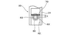
図3および図4に示すように、第2挟持部材30の挟持部31の内面、より詳細には指収容部42の内面には、第1挟持部材20の挟持部21と第2挟持部材30の挟持部31との間に被験者の手の指を挟持したときに、この指の爪の甘皮に引っ掛かることにより第1挟持部材20および第2挟持部材30に対する指の長手方向前方への移動を阻止する甘皮ストッパー70が設けられている。図5は挟持部31の内面を示す。図5に示すように、この甘皮ストッパー70は、指収容部41、42に被験者の手の指を収容し、第1挟持部材20の挟持部21と第2挟持部材30の挟持部31との間に指を挟持した状態で指の爪を指に直交する方向に横断するように回動軸10に平行な方向に延在している。この甘皮ストッパー70の、第1挟持部材20の挟持部21に臨む先端部は回動軸10に平行になっている。また、この甘皮ストッパー70の延在方向に垂直な方向の断面形状は台形状となっている。この台形状の断面形状を有する甘皮ストッパー70の指挿入側の側面が指の爪の甘皮に引っ掛かるようになっている。この場合、甘皮ストッパー70の指挿入側の側面が指の爪に対して鋭角となっているため、甘皮ストッパー60の先端を指の爪の甘皮に引っ掛ける時に甘皮や爪などが傷つくのを防止することができる。この甘皮ストッパー70の断面形状の台形の上底と指挿入側の側面との交点(交線)と顕微鏡本体60の光軸との間の距離Dは、観察時に指の爪の甘皮に甘皮ストッパー70の先端が引っ掛かった状態で顕微鏡本体60の光軸が甘皮に隣接する爪根部の表皮に位置するように選択される。距離Dは、例えば、1.0mm以上2.0mm以下、あるいは1.2mm以上1.8mm以下、あるいは1.3mm以上1.6mm以下、例えば1.4mmである。甘皮ストッパー60の下底の長さは例えば1mm以上2mm以下、例えば1.5mm、上底の長さは例えば0.5mm以上1.5mm以下、例えば1mmである。必要に応じて、甘皮ストッパー60の先端部の角部を直線状または円弧などの曲線状に面取りしてもよい。こうすることで、甘皮ストッパー60の先端を指の爪の甘皮に引っ掛ける時に甘皮や爪などが傷つくのをより確実に防止することができる。図5には、顕微鏡本体60の先端部が示されており、照明光学系として光軸の周りの円周上に対物レンズ62を取り囲むように等間隔で取り付けられている複数(例えば、8個)の発光ダイオードの照明領域63が示されている。 As shown in FIGS. 3 and 4, on the inner surface of the holding
[指先毛細血管血流観察顕微鏡の使用方法]
この指先毛細血管血流観察顕微鏡を用いて被験者の手の指先の毛細血管の血流を観察する方法について説明する。[How to use the fingertip capillary blood flow observation microscope]
A method of observing the blood flow of the capillaries of the fingertips of the subject's hand using this fingertip capillary blood flow observation microscope will be described.
図6は指先の毛細血管の血流を観察する場所を示す。図6に示すように、指の爪の甘皮に隣接する爪根部の表皮が観察場所となる。 FIG. 6 shows a place for observing blood flow in the capillaries of the fingertips. As shown in FIG. 6, the epidermis at the base of the nail adjacent to the cuticle of the fingernail is the observation site.
まず、この指先毛細血管血流観察顕微鏡の第1挟持部材20の操作部22と第2挟持部材30の操作部32とを手の指でつまんで力を加えることにより第1挟持部材20の挟持部21と第2挟持部材30の挟持部31とを互いに離す。 First, the
この状態で第1挟持部材20の挟持部21と第2挟持部材30の挟持部31との間の隙間から、被験者の手の、指先の毛細血管の血流を観察しようとする指、典型的には利き手の反対側の手の薬指を挿入し、指収容部41、42に収容する。好適には、その指の爪の甘皮の直ぐ後方の部分には予め少量のオイルを塗っておく。オイルを塗るのは、爪根部の表皮での照明光の反射を抑え、毛細血管の血流を観察しやすくするためである。この後、第1挟持部材20の操作部22と第2挟持部材30の操作部32とに力を加えるのを止める。こうすることで、挟みばね50が初期の状態に復元しようとすることにより第1挟持部材20の挟持部21と第2挟持部材30の挟持部31との間に指が挟持される。このとき、指収容部41、42に収容された指は回動軸10に平行な方向および垂直な方向に拘束される。この状態で指を少し前に移動させ、甘皮ストッパー70の指の挿入側の側面が甘皮に引っ掛かるようにする。この状態を図7〜図10に示す。ここで、図7は斜視図、図8は右側面図、図9は指収容部41、42に指を挿入した状態において指収容部41、42の奥から指先を見た略線図である。図10は甘皮ストッパー70が指の先端の甘皮近傍に位置している様子を示す。 In this state, a finger that attempts to observe the blood flow of the capillaries of the fingertip of the subject's hand through the gap between the sandwiching
その後、自動もしくは手動で顕微鏡本体60のピント合わせを行い、顕微鏡本体60の対物レンズの焦点を爪の甘皮の近傍の爪根部の表皮に合わせる。手動でピント合わせを行う場合には、顕微鏡本体60の焦点調整ダイヤル61を回すことにより、顕微鏡本体60の対物レンズの焦点を爪の甘皮の近傍の爪根部の表皮に合わせる。こうして焦点合わせを行った後、顕微鏡本体60により爪根部の表皮を介して指先の毛細血管の血流を観察する。こうして観察される画像は撮像素子により撮像され、その画像がケーブルを介してコンピュータのディスプレイやスマートフォンのディスプレイに送られ、これらのディスプレイに表示される。こうして、ディスプレイ上で指先の毛細血管の血流を観察することができる。 After that, the microscope
以上のように、この第1の実施の形態によれば、被験者が指先の毛細血管の血流を観察しようとする手の指を第1挟持部材20の挟持部21と第2挟持部材30の挟持部31との間の隙間から指収容部41、42に挿入し、甘皮ストッパー70の先端の指の挿入側の側面を指の爪の甘皮に引っ掛け、指を回動軸10に平行な方向および垂直な方向に拘束した状態で顕微鏡本体60のピントを指の爪の甘皮に隣接する爪根部の表皮に合わせるだけで毛細血管の血流を簡単にしかも鮮明に観察することができる。 As described above, according to the first embodiment, the finger of the hand on which the subject intends to observe the blood flow of the capillaries of the fingertip is held by the holding
〈第2の実施の形態〉
[指先毛細血管血流観察顕微鏡]
図11〜図13は第2の実施の形態による指先毛細血管血流観察顕微鏡を示し、図11は斜視図、図12は平面図、図13は正面図である。<Second Embodiment>
[Fingertip capillary blood flow observation microscope]
11 to 13 show a fingertip capillary blood flow observation microscope according to the second embodiment, FIG. 11 is a perspective view, FIG. 12 is a plan view, and FIG. 13 is a front view.
図11〜図13に示すように、この指先毛細血管血流観察顕微鏡は、第1挟持部材20および第2挟持部材30に、挟持部21と挟持部31との間に挟持された指および甘皮ストッパー70の状態を外部から観察するための観察用窓33が設けられていることが第1の実施の形態による指先毛細血管血流観察顕微鏡と異なり、その他の構成は第1の実施の形態による指先毛細血管血流観察顕微鏡と同様である。 As shown in FIGS. 11 to 13, in this fingertip capillary blood flow observation microscope, the fingers and cuticles sandwiched between the sandwiching
[指先毛細血管血流観察顕微鏡の使用方法]
この指先毛細血管血流観察顕微鏡の使用方法は第1の実施の形態による指先毛細血管血流観察顕微鏡と同様である。[How to use the fingertip capillary blood flow observation microscope]
The method of using the fingertip capillary blood flow observation microscope is the same as that of the fingertip capillary blood flow observation microscope according to the first embodiment.
この第2の実施の形態によれば、第1の実施の形態と同様な利点に加えて、挟持部21と挟持部31との間に指を挟持した状態で観察用窓33から指および甘皮ストッパー70の状態を観察することにより、甘皮ストッパー70の先端が指の爪の甘皮に引っ掛かっていることを確認した上で指の毛細血管の血流を観察することができるという利点を得ることができる。 According to this second embodiment, in addition to the same advantages as in the first embodiment, the finger and the cuticle from the
以上、この発明の実施の形態について具体的に説明したが、この発明は上述の実施の形態に限定されるものではなく、この発明の技術的思想に基づく各種の変形が可能である。 Although the embodiments of the present invention have been specifically described above, the present invention is not limited to the above-described embodiments, and various modifications based on the technical idea of the present invention are possible.
例えば、上述の実施の形態において挙げた数値、構成、形状、材料、方法などはあくまでも例に過ぎず、必要に応じてこれらと異なる数値、構成、形状、材料、方法などを用いてもよい。 For example, the numerical values, configurations, shapes, materials, methods and the like given in the above-described embodiments are merely examples, and numerical values, configurations, shapes, materials, methods and the like different from these may be used as necessary.
例えば、上述の第1の実施の形態においては、第1挟持部材20の操作部22と第2挟持部材30の操作部32との間に挟みばね50を取り付けることにより第1挟持部材20および第2挟持部材30を初期位置に復元可能に構成しているが、挟みばね50を取り付けず、代わりに第1挟持部材20および第2挟持部材30の回動部にねじりコイルばねを取り付けることにより第1挟持部材20および第2挟持部材30を初期位置に復元可能に構成してもよい。 For example, in the first embodiment described above, the first holding
10…回動軸、20…第1挟持部材、21…挟持部、22…操作部、30…第2挟持部材、31…挟持部、32…操作部、33…観察用窓、41、42…指収容部、50…挟みばね、60…顕微鏡本体、61…焦点調整ダイヤル、62…対物レンズ、70…甘皮ストッパー 10 ... Rotating shaft, 20 ... First holding member, 21 ... Holding part, 22 ... Operating part, 30 ... Second holding member, 31 ... Holding part, 32 ... Operating part, 33 ... Observation window, 41, 42 ... Finger housing, 50 ... pinching spring, 60 ... microscope body, 61 ... focus adjustment dial, 62 ... objective lens, 70 ... cuticle stopper
Claims (3)
Translated fromJapanese上記第1挟持部材の挟持部および上記第2挟持部材の挟持部の互いに対向する内面に設けられた、上記第1挟持部材の上記挟持部と上記第2挟持部材の上記挟持部との間に上記回動軸に垂直な方向から被験者の手の、指先の毛細血管の血流を観察しようとする指を挿入したときに当該指を当該指に垂直でかつ上記回動軸に平行な方向に拘束した状態で収容する指収容部と、
先端部が上記第1挟持部材の上記挟持部に臨むように上記第2挟持部材に取り付けられたピント合わせ機能を有する顕微鏡本体と、
上記第2挟持部材の上記挟持部の内面に設けられた、上記第1挟持部材の上記挟持部と上記第2挟持部材の上記挟持部との間に上記指を挟持したときに、上記指の爪の甘皮に引っ掛かることにより上記第1挟持部材および上記第2挟持部材に対する上記指の長手方向前方への移動を阻止する甘皮ストッパーとを有し、
上記甘皮ストッパーの先端が上記指の爪の甘皮に引っ掛った状態において、上記顕微鏡本体の光軸が上記指の爪の甘皮に隣接する爪根部に合うように構成されている指先毛細血管血流観察顕微鏡。A first holding member and a second holding member configured to be rotatable around a rotation shaft and reversible to the initial position,
Between the sandwiching portion of the first sandwiching member and the sandwiching portion of the second sandwiching member provided on the inner surfaces of the sandwiching portion of the first sandwiching member and the sandwiching portion of the second sandwiching member facing each other. When a finger for observing the blood flow of the capillaries of the fingertip of the subject's hand is inserted from a direction perpendicular to the rotation axis, the finger is placed in a direction perpendicular to the finger and parallel to the rotation axis. A finger accommodating part that accommodates in a restrained state,
A microscope main body having a focusing function attached to the second holding member so that the tip portion faces the holding portion of the first holding member.
When the finger is sandwiched between the sandwiching portion of the first sandwiching member and the sandwiching portion of the second sandwiching member provided on the inner surface of the sandwiching portion of the second sandwiching member, the finger It has a cuticle stopper that prevents the finger from moving forward in the longitudinal direction with respect to the first holding member and the second holding member by being caught on the cuticle of the nail.
When the tip of the cuticle stopper is caught on the cuticle of the fingernail, the optical axis of the microscope body is configured to be aligned with the nail root portion adjacent to the cuticle of the fingernail. Observation microscope.
Priority Applications (1)
| Application Number | Priority Date | Filing Date | Title |
|---|---|---|---|
| JP2019189080AJP6675629B1 (en) | 2019-10-16 | 2019-10-16 | Fingertip capillary blood flow observation microscope |
Applications Claiming Priority (1)
| Application Number | Priority Date | Filing Date | Title |
|---|---|---|---|
| JP2019189080AJP6675629B1 (en) | 2019-10-16 | 2019-10-16 | Fingertip capillary blood flow observation microscope |
Publications (2)
| Publication Number | Publication Date |
|---|---|
| JP6675629B1 JP6675629B1 (en) | 2020-04-01 |
| JP2021063930Atrue JP2021063930A (en) | 2021-04-22 |
Family
ID=70000993
Family Applications (1)
| Application Number | Title | Priority Date | Filing Date |
|---|---|---|---|
| JP2019189080AActiveJP6675629B1 (en) | 2019-10-16 | 2019-10-16 | Fingertip capillary blood flow observation microscope |
Country Status (1)
| Country | Link |
|---|---|
| JP (1) | JP6675629B1 (en) |
Citations (9)
| Publication number | Priority date | Publication date | Assignee | Title |
|---|---|---|---|---|
| US4685464A (en)* | 1985-07-05 | 1987-08-11 | Nellcor Incorporated | Durable sensor for detecting optical pulses |
| JPH0288041A (en)* | 1988-09-24 | 1990-03-28 | Misawahoomu Sogo Kenkyusho:Kk | Finger tip pulse wave sensor |
| JPH057203U (en)* | 1991-05-15 | 1993-02-02 | 日本光電工業株式会社 | Photoelectric pulse wave measurement probe |
| US5551422A (en)* | 1992-11-09 | 1996-09-03 | Boehringer Mannheim Gmbh | Method and apparatus for analytical determination of glucose in a biological matrix |
| WO1999000053A1 (en)* | 1997-06-27 | 1999-01-07 | Toa Medical Electronics Co., Ltd. | Living body inspecting apparatus and noninvasive blood analyzer using the same |
| US20040181132A1 (en)* | 2003-03-14 | 2004-09-16 | Rosenthal Robert D. | Low-cost method and apparatus for non-invasively measuring blood glucose levels |
| JP2007054483A (en)* | 2005-08-26 | 2007-03-08 | Olympus Corp | Wearable microscope system |
| JP2009507604A (en)* | 2005-09-13 | 2009-02-26 | グルコスタッツ・システム・プライヴェト・リミテッド | A device that provides a constant contact pressure to the probe |
| WO2010073913A1 (en)* | 2008-12-26 | 2010-07-01 | コニカミノルタセンシング株式会社 | Probe for measuring living body information |
- 2019
- 2019-10-16JPJP2019189080Apatent/JP6675629B1/enactiveActive
Patent Citations (9)
| Publication number | Priority date | Publication date | Assignee | Title |
|---|---|---|---|---|
| US4685464A (en)* | 1985-07-05 | 1987-08-11 | Nellcor Incorporated | Durable sensor for detecting optical pulses |
| JPH0288041A (en)* | 1988-09-24 | 1990-03-28 | Misawahoomu Sogo Kenkyusho:Kk | Finger tip pulse wave sensor |
| JPH057203U (en)* | 1991-05-15 | 1993-02-02 | 日本光電工業株式会社 | Photoelectric pulse wave measurement probe |
| US5551422A (en)* | 1992-11-09 | 1996-09-03 | Boehringer Mannheim Gmbh | Method and apparatus for analytical determination of glucose in a biological matrix |
| WO1999000053A1 (en)* | 1997-06-27 | 1999-01-07 | Toa Medical Electronics Co., Ltd. | Living body inspecting apparatus and noninvasive blood analyzer using the same |
| US20040181132A1 (en)* | 2003-03-14 | 2004-09-16 | Rosenthal Robert D. | Low-cost method and apparatus for non-invasively measuring blood glucose levels |
| JP2007054483A (en)* | 2005-08-26 | 2007-03-08 | Olympus Corp | Wearable microscope system |
| JP2009507604A (en)* | 2005-09-13 | 2009-02-26 | グルコスタッツ・システム・プライヴェト・リミテッド | A device that provides a constant contact pressure to the probe |
| WO2010073913A1 (en)* | 2008-12-26 | 2010-07-01 | コニカミノルタセンシング株式会社 | Probe for measuring living body information |
Also Published As
| Publication number | Publication date |
|---|---|
| JP6675629B1 (en) | 2020-04-01 |
Similar Documents
| Publication | Publication Date | Title |
|---|---|---|
| US20140171735A1 (en) | Retrieval basket apparatus | |
| US12089876B2 (en) | Skin care methods, systems, and devices | |
| EA017088B1 (en) | Diagnostic camera and attachment for the implementation thereof | |
| WO2023133297A2 (en) | Collapsible dental scope | |
| EP1643415A3 (en) | Fingerprint image pickup device | |
| US10098531B2 (en) | Visualization apparatus and system for enhanced hand-eye coordination | |
| JP6675629B1 (en) | Fingertip capillary blood flow observation microscope | |
| JP2004065623A (en) | Root canal endoscope and root canal endoscope system | |
| EP3305166A1 (en) | Medical manipulator system | |
| WO2019181042A1 (en) | Endoscope insertion aid, endoscope system | |
| Bahcall | Visualization in endodontics | |
| JP6598414B1 (en) | Fingertip capillary blood flow observation microscope | |
| JP2008015033A (en) | Magnification imaging device | |
| CN211355366U (en) | endoscope | |
| KR20180138037A (en) | Endoscopic imaging catheter | |
| JPWO2021090358A5 (en) | Endoscope device, image output method for display, program, and endoscope system | |
| JPWO2016103805A1 (en) | Imaging device | |
| JP6496242B2 (en) | Camera and wearable system | |
| JPWO2019143587A5 (en) | ||
| JP2019015774A (en) | Head, microscope, and method for observation | |
| DE50310502D1 (en) | Endoscope eyepiece | |
| JP3002561U (en) | Grasping structure of dental visual equipment | |
| KR20090122084A (en) | Microscope to Examine Blood Flow and Demodex | |
| JP2023081249A (en) | Microscope and observation method | |
| US20160022376A1 (en) | Mirror, in particular medical mirror, and device, in particular for root canal treatment |
Legal Events
| Date | Code | Title | Description |
|---|---|---|---|
| A621 | Written request for application examination | Free format text:JAPANESE INTERMEDIATE CODE: A621 Effective date:20191018 | |
| A871 | Explanation of circumstances concerning accelerated examination | Free format text:JAPANESE INTERMEDIATE CODE: A871 Effective date:20191018 | |
| A975 | Report on accelerated examination | Free format text:JAPANESE INTERMEDIATE CODE: A971005 Effective date:20191101 | |
| A977 | Report on retrieval | Free format text:JAPANESE INTERMEDIATE CODE: A971007 Effective date:20200207 | |
| TRDD | Decision of grant or rejection written | ||
| A01 | Written decision to grant a patent or to grant a registration (utility model) | Free format text:JAPANESE INTERMEDIATE CODE: A01 Effective date:20200225 | |
| A61 | First payment of annual fees (during grant procedure) | Free format text:JAPANESE INTERMEDIATE CODE: A61 Effective date:20200226 | |
| R150 | Certificate of patent or registration of utility model | Ref document number:6675629 Country of ref document:JP Free format text:JAPANESE INTERMEDIATE CODE: R150 | |
| S802 | Written request for registration of partial abandonment of right | Free format text:JAPANESE INTERMEDIATE CODE: R311802 | |
| R350 | Written notification of registration of transfer | Free format text:JAPANESE INTERMEDIATE CODE: R350 | |
| R250 | Receipt of annual fees | Free format text:JAPANESE INTERMEDIATE CODE: R250 | |
| R250 | Receipt of annual fees | Free format text:JAPANESE INTERMEDIATE CODE: R250 |