JP2021061328A - Device and method for molding composition on substrate using mold, and method for manufacturing article - Google Patents
Device and method for molding composition on substrate using mold, and method for manufacturing articleDownload PDFInfo
- Publication number
- JP2021061328A JP2021061328AJP2019184784AJP2019184784AJP2021061328AJP 2021061328 AJP2021061328 AJP 2021061328AJP 2019184784 AJP2019184784 AJP 2019184784AJP 2019184784 AJP2019184784 AJP 2019184784AJP 2021061328 AJP2021061328 AJP 2021061328A
- Authority
- JP
- Japan
- Prior art keywords
- substrate
- mold
- wall portion
- gas
- wall
- Prior art date
- Legal status (The legal status is an assumption and is not a legal conclusion. Google has not performed a legal analysis and makes no representation as to the accuracy of the status listed.)
- Pending
Links
Images


Landscapes
- Shaping Of Tube Ends By Bending Or Straightening (AREA)
- Exposure Of Semiconductors, Excluding Electron Or Ion Beam Exposure (AREA)
Abstract
Translated fromJapaneseDescription
Translated fromJapanese型を用いて基板上の組成物を成形する成形装置、成形方法、及び、物品製造方法に関する。 The present invention relates to a molding apparatus, a molding method, and an article manufacturing method for molding a composition on a substrate using a mold.
半導体デバイスやMEMSなどの物品を製造する方法として、型(モールド)を用いて基板上のインプリント材(組成物)を成形するインプリント方法が知られている。インプリント技術とは、基板上に供給されたインプリント材と型とを接触させ、インプリント材に硬化用のエネルギーを与えることにより、型の凹凸パターンが転写された硬化物のパターンを形成する微細加工技術である。 As a method for manufacturing articles such as semiconductor devices and MEMS, an imprint method for molding an imprint material (composition) on a substrate using a mold is known. In the imprint technology, the imprint material supplied on the substrate is brought into contact with the mold, and energy for curing is given to the imprint material to form a pattern of the cured product to which the uneven pattern of the mold is transferred. It is a microfabrication technology.
特許文献1は、インプリント装置を用いて基板の表面を平坦化する成形技術を開示している。従来、基板の表面を平坦化する成形技術に関しては、既存の塗布装置(スピンコーター)を用いて基板上にインプリント材などの組成物の塗布膜を形成することで基板の表面の段差を平坦化する成形技術が知られている。しかし、このような成形技術は、基板の表面の段差をナノスケールで平坦化するには不十分である。一方、特許文献1に開示された技術は、基板の段差に基づいて光硬化性のインプリント材を供給し、供給されたインプリント材に平坦な表面を有する型を接触させた状態でインプリント材を硬化することで平坦化の精度を向上させるものである。
基板の表面を平坦化させる技術やインプリント技術においては、型と基板上のインプリント材との間に気泡が残留すると、インプリント材が基板全面に十分に広がらずに未充填が発生し、基板上に形成される塗布膜層やパターンの欠陥の原因となりうる。このため、特許文献2では、モールドと基板との間に、可溶性が高いか、拡散性が高いか、あるいは、その両方であるガスを流し込み、基板とモールドとの隙間の空気を置換する技術を開示している。また、特許文献3では、凝縮性気体を用い、凝縮性気体雰囲気中でインプリントを実施し、気体を液化させることで未充填となる領域を最小にする旨の技術を開示している。 In the technique of flattening the surface of the substrate and the imprinting technique, if air bubbles remain between the mold and the imprint material on the substrate, the imprint material does not spread sufficiently over the entire surface of the substrate and unfilling occurs. It can cause defects in the coating film layer and pattern formed on the substrate. Therefore, in Patent Document 2, a technique is provided in which a gas having high solubility, high diffusivity, or both is poured between the mold and the substrate to replace the air in the gap between the substrate and the mold. It is disclosed. Further, Patent Document 3 discloses a technique of performing imprinting in a condensable gas atmosphere using a condensing gas and liquefying the gas to minimize an unfilled region.
型と基板表面のインプリント材等の組成物との間に気泡が残留すると、インプリント材が基板全面に十分に広がらず、インプリント材層の欠陥や基板の凹凸構造へのインプリント材の未充填が生じるおそれがある。しかしながら、平坦化処理を行う成形装置へ特許文献2の技術を適用する際、型と基板との間の容積が、通常のインプリント装置におけるモールドと基板との間の容積より数十倍大きい。このため、空気から気体への置換に時間を要し、必要な気体濃度まで上げづらい。また、特許文献3のように成形装置においても密閉された処理室内の気体雰囲気下で平坦化処理を行う場合、基板交換の度に処理室全体へ気体を再充填することになり、多量の気体を必要とし、運転コストの増大と生産性の低下を招くおそれがある。 If air bubbles remain between the mold and the composition such as the imprint material on the surface of the substrate, the imprint material does not spread sufficiently over the entire surface of the substrate, and the imprint material has defects in the imprint material layer or the imprint material on the uneven structure of the substrate. Unfilling may occur. However, when the technique of Patent Document 2 is applied to a molding apparatus that performs a flattening treatment, the volume between the mold and the substrate is several tens of times larger than the volume between the mold and the substrate in a normal imprinting apparatus. Therefore, it takes time to replace air with gas, and it is difficult to raise the required gas concentration. Further, when the flattening treatment is performed in a gas atmosphere in a closed processing chamber even in a molding apparatus as in Patent Document 3, the entire processing chamber is refilled with gas every time the substrate is replaced, and a large amount of gas is used. Is required, which may lead to an increase in operating cost and a decrease in productivity.
本発明は、上記課題を解決し、例えば、気体の供給量と欠陥の発生を低減する点で有利な成形装置を提供することを目的とする。 An object of the present invention is to solve the above problems and to provide a molding apparatus which is advantageous in reducing the supply amount of gas and the occurrence of defects, for example.
上記課題を解決するために、本発明は、型を用いて基板上の組成物を成形する成形装置であって、前記基板を保持する基板保持部と、前記型を保持する型保持部と、前記型保持部に保持された前記型と、前記基板保持部に保持された前記基板との間の隙間に気体を供給する気体供給部と、前記気体が供給される前記隙間を囲むように配置される壁部と、前記壁部を制御する制御部と、を有し、前記制御部は、前記壁部によって囲まれた空間を、前記基板の表面方向において、前記基板の中心に向かって狭めるように、前記壁部の少なくとも一部を前記基板に垂直な方向に駆動させることを特徴とする。 In order to solve the above problems, the present invention is a molding apparatus for molding a composition on a substrate using a mold, which comprises a substrate holding portion for holding the substrate, a mold holding portion for holding the mold, and the like. A gas supply unit that supplies gas to the gap between the mold held by the mold holding unit and the substrate held by the substrate holding unit, and a gas supply unit that supplies the gas are arranged so as to surround the gap to which the gas is supplied. It has a wall portion to be formed and a control unit for controlling the wall portion, and the control unit narrows the space surrounded by the wall portion toward the center of the substrate in the surface direction of the substrate. As described above, at least a part of the wall portion is driven in a direction perpendicular to the substrate.
本発明によれば、例えば、気体の供給量と欠陥の発生を低減する点で有利な成形装置を提供することができる。 According to the present invention, for example, it is possible to provide a molding apparatus which is advantageous in reducing the supply amount of gas and the occurrence of defects.
以下、添付図面を参照して、本発明の好適な実施の形態について説明する。なお、各図において、同一の部材については同一の参照番号を付し、重複する説明は省略する。
<第1実施形態>Hereinafter, preferred embodiments of the present invention will be described with reference to the accompanying drawings. In addition, in each figure, the same member is given the same reference number, and duplicate description is omitted.
<First Embodiment>
図1は、第1実施形態に係る成形装置100の構成の一部を示す概略図である。ここでは、水平面をXY平面とし、鉛直方向をZ軸方向とするようにXYZ座標系が定義されている。成形装置100は、型(モールド、テンプレート)を用いて基板上のインプリント材(組成物、成形可能材料)を成形する装置(所謂、インプリント装置)で具現化され、本実施形態では、基板上のインプリント材を平坦化する平坦化装置である。平坦化装置は、基板上のインプリント材と型とを接触させた状態でインプリント材を硬化させ、硬化したインプリント材から型を引き離すことで基板上にインプリント材の平坦面を形成する。 FIG. 1 is a schematic view showing a part of the configuration of the
成形装置100は、インプリント材としての光硬化性組成物を成形する。硬化性組成物は、硬化用のエネルギーが与えられることにより硬化する物(未硬化状態の樹脂と呼ぶこともある)である。硬化用のエネルギーとしては、電磁波、熱等が用いられうる。ここでは、硬化用のエネルギーとして紫外線を用いる装置の例で説明するが、これに限られない。 The
また、本実施形態では、基板Wとして半導体製造において典型的に使用される基板を用いた例で説明するがこれに限られない。典型的な基板は、直径300mmあるいは200mmの円形の外周形状を有する。基板の材料としては、例えば、シリコン、ガラス、セラミックス、金属、樹脂等が用いられうる。必要に応じて、基板の表面に、基板とは別の材料からなる部材が設けられてもよい。基板は、例えば、シリコン基板、化合物半導体基板、石英ガラスである。 Further, in the present embodiment, an example in which a substrate typically used in semiconductor manufacturing is used as the substrate W will be described, but the present invention is not limited to this. A typical substrate has a circular outer shape with a diameter of 300 mm or 200 mm. As the material of the substrate, for example, silicon, glass, ceramics, metal, resin and the like can be used. If necessary, a member made of a material different from the substrate may be provided on the surface of the substrate. The substrate is, for example, a silicon substrate, a compound semiconductor substrate, or quartz glass.
また、型SSは、例えば、円形又は四角形の外形を有し、基板上のインプリント材に接触して基板Wの表面形状に倣う平面部11を含む。平面部11は、基板Wと同じ大きさ、又は、基板Wよりも大きい大きさを有する。本実施形態では、型SSは、基板Wと同サイズの円形の外周形状を有する型の例で説明する。 Further, the mold SS has, for example, a circular or quadrangular outer shape, and includes a
図1に示す成形装置100は、成形処理部101を有する。成形処理部101は、基板Wを保持して移動するステージ(支持台)1と、型SSを保持して上下駆動するヘッド52と、照射部70と、観察部71、制御部80とを有する。 The
観察部71は、基板上のインプリント材と型SSとの接触状態、基板上のインプリント材の型SSへの充填状態、基板上のインプリント材からの型SSの分離状態を、画像情報として観察することが可能である。観察部71で基板W上のインプリント材MLを観察しながら、型SSをインプリント材MLへ接触させ、この状態でインプリント材MLに照射部70から光を照射し、インプリント材MLを硬化させる。 The
型SSは平坦な表面(平面部11)を有しているため、硬化後に型SSを上方に移動させると、硬化されたインプリント材MLの表面には型SSの表面に応じた面が形成される。このようにして、インプリント材を成形する。 Since the mold SS has a flat surface (flat surface portion 11), when the mold SS is moved upward after curing, a surface corresponding to the surface of the mold SS is formed on the surface of the cured imprint material ML. Will be done. In this way, the imprint material is molded.
ステージ1は、基板Wを保持するための基板保持部10を支持する支持台である。ステージ1は、例えば、リニアモータやエアシリンダなどを含み、少なくともX軸方向及びY軸方向に移動する。ステージ1は、2軸以上の方向(例えば、6軸方向)に駆動する機能を有していてもよい。また、ステージ1は、例えば、回転機構を含み、Z軸方向に平行な軸周りに回転可能であっても良い。ステージ1は、基板Wを基板保持部10に保持させた状態で、ベースBS上を移動可能である。基板Wを基板保持部10上に搬入または搬出する際に、ヘッド52の下方から離れた位置にステージ1を移動させることで、搬送ハンド(不図示)とヘッド52との干渉(物理的接触)の回避が容易となる。また、基板W上のインプリント材MLと型SSとを接触させる前にステージ1を微小量で移動させることで、型SSと基板Wとの相対位置を微調整することができる。ステージを駆動する機構については公知の技術を適用しうる。 The
基板保持部10は、ステージ1に締結あるいは吸着により固定される。基板保持部10は基板Wを保持する保持面を有する。基板保持部10による基板Wの保持方式として、真空吸着方式、静電吸着方式などの公知の技術を適用しうる。真空吸着方式の場合には、基板保持部10の表面に形成された溝と負圧発生装置と連通させ、基板Wが保持面に載置された状態で溝の内部を負圧にすることで基板Wを保持することができる。基板保持部10には、基板Wを搬入および搬出する際にピンを保持面から突出させるための孔が形成されていてもよい。ピンを上下に駆動する機構を用いてピンを保持面から突出させることで、保持面から離間させた状態でピンに支持された基板Wを搬送ハンドに受け渡すことができる。また、ステージ1は、型SSを搬送ハンドに受け渡す際に使用されてもよい。ステージ1と基板保持部10の材質は公知の技術を適用しうる。例えば、セラミックス、金属、合金、ガラスなどの材質であってもよい。 The
続いてヘッド52について説明する。型保持部50は型SSを保持する保持面を有する。型保持部50による型SSの保持方式として、真空吸着方式、静電吸着方式などの公知の技術を適用しうる。真空吸着方式の場合には、型保持部50の表面に形成された複数の真空吸着溝503と負圧発生装置とを連通させ、型SSが保持面に載置された状態で溝の内部を負圧にすることで型SSを保持することができる。 Subsequently, the
型保持部50は、型SSの直径よりも大きな直径の円形の外周形状を有する。型保持部50は、型SSを保持した状態で、型保持部50の上方からの光をインプリント材MLに照射可能に構成される。そのために、型保持部50の材質の少なくとも一部を、紫外光の透過率が60%以上の材質としうる。より好適には、紫外光の透過率を70%以上あるいは80%以上の材質としうる。本実施形態では、型保持部50のうち、型SSと接触しない領域の材質も型SSと接触する領域と同様に紫外光の透過率が高い材質としている。また、透過率が高い材質を配置する代わりに、型保持部50の一部に凹部(空間)を形成して、光の照射を妨げないようにしてもよい。 The
駆動部51はヘッド52に支持される。駆動部51は、ヘッド52に対する型保持部50の上下方向(Z方向)の相対位置を変化させるように型保持部50を駆動する。なお、ステージ1をZ軸方向に駆動することにより、型SSと基板上のインプリント材とを接触させたり、引き離したりしても良い。駆動部51として、例えば、ピエゾアクチュエータやボイスコイルモータなどのアクチュエータを用いることができる。要求される仕様(応答性など)によっては空圧を利用したものであってもよい。型保持部50をチルト方向(θx、θy方向)に駆動可能なように複数のアクチュエータを設けてもよい。型保持部50をチルト方向に駆動することで、型SSとインプリント材MLとを接触させる際に型SSと基板Wとの相対的な傾きを調整することができる。駆動部51は、型保持部50をXY方向に移動可能であってもよい。例えば、基板W上のインプリント材MLと型SSとを接触させる前にXY方向に型保持部50を微小量で移動させることで、型SSと基板Wとの相対位置を微調整することができる。 The
ヘッド52は不図示の支持構造体に、例えば、締結により固定される。駆動部51とヘッド52は、筐体に収納されていてもよい。この場合、駆動部51とヘッド52は筐体を介して支持構造体に固定されてもよい。また、ヘッド52が筐体を兼ねていてもよい。 The
ヘッド52は、さらに、型保持部50に保持された型SSを基板Wに向けて湾曲させるための機構を有してもよい。例えば、型保持部50に凹部Pを形成し、保持された型SSと凹部Pとで囲まれた局所空間を圧力制御部60に連通させて、局所空間の圧力を陽圧にすることで、型SSを湾曲させることができる。 The
また、ヘッド52は、型SSとインプリント材MLとの間の隙間Hへ気体Qを供給するための気体供給部61と、型保持部50へ連通する圧力制御部60を有する。 Further, the
成形処理部101は、型SSと接触させているインプリント材MLを観察する観察部71を有する。観察部71は、観察光を照射するための光源と、撮像素子(撮像手段)とを有する。光源の波長は、インプリント材の硬化に用いる光の波長とは異なることが好ましく、本実施形態では可視光線である450nm〜750nmの波長域のLEDを用いる。光源からの観察光は光学部材72と光学部材73を介して型保持部50の上方からインプリント材に照射される。本実施形態では光学部材72により観察部光路Cと照射部光路ILを合成し、光学部材73によりテレセントリック光学系を構成している。このような構成で、成形動作中の型SSとインプリント材MLの状態を観察することができる。観察部71は成形される領域全域で観察することが好ましい。 The
制御部80は、CPU等のプロセッサと、RAM、ROM、HDD等の記憶部と、外部デバイスとプロセッサとをインターフェースするインターフェース部と、を含む。インターフェース部には、ホストコンピュータとの通信を行う通信インターフェースも含まれる。ホストコンピュータは、例えば、成形装置100が配置された工場全体または一領域を制御するコンピュータである。プロセッサは記憶部に記憶されたプログラムを実行し、成形処理部101の動作を制御する。制御部80は、複数の回路基板を有していてもよい。また、制御部80の全部あるいは一部は、成形処理部が配置されるチャンバ(筐体)内のラックに配置されてもよく、チャンバ外に配置されてもよい。 The
ここで、図2を参照しながら、成形処理部101を用いた成形動作について説明する。図2は、第1実施形態に係る成形処理を説明する図である。本実施例では、平坦な表面を有する型を用いて成形を行う装置について説明をする。まず、インプリント材MLが供給(塗布)された基板Wを基板保持部10に載置する。次に、基板保持部10に保持された基板Wを型保持部50に保持された型SSに対向させる。さらに、駆動部51により型SSを下方(基板Wの方向)に降下させて(図2(A)の状態)、型SSとインプリント材MLを接触させる。この時、基板Wを型SSに向かって上昇させても良い。その後、照射部70から光UVを照射し、光学部材72、光学部材73、および型SSを介して光UVをインプリント材MLに照射する(図2(B)の状態)。 Here, a molding operation using the
この結果、インプリント材MLの光硬化反応が発生し、インプリント材MLが硬化する。最後に、硬化したインプリント材MLから、駆動部51により型SSを剥離(離型)させる(図2(C)の状態)。 As a result, a photocuring reaction of the imprint material ML occurs, and the imprint material ML is cured. Finally, the mold SS is peeled (released) from the cured imprint material ML by the drive unit 51 (state of FIG. 2C).
以上のような工程で、基板W上に成形されたインプリント材MLを形成することができる。このような成形処理は、基板Wの全面に対して一括で行われる。ここで、本実施形態では型SSとして、厚さ0.3mm以上1.0mm以下、より好適には、厚さ0.5mm以上0.7mm以下の部材を用いている。型SSは、紫外光を透過可能な材質であり、石英などが好適に用いられる。本実施形態の成形装置100に用いられる型SSは回路パターンのようなデバイス用途のパターンを有さず、平坦な面を有する。このような型は、平坦化部材あるいはスーパーストレートと称されることもある。型SSは、デバイス用途ではなく位置合わせ用途のパターン(マーク)を有していてもよい。このようなパターン(マーク)は、例えば成形処理において型SSと基板Wとの相対位置を調整するために用いられ、アライメントマークと称されることがある。 By the above steps, the imprint material ML formed on the substrate W can be formed. Such a molding process is collectively performed on the entire surface of the substrate W. Here, in the present embodiment, as the mold SS, a member having a thickness of 0.3 mm or more and 1.0 mm or less, more preferably 0.5 mm or more and 0.7 mm or less is used. The type SS is a material capable of transmitting ultraviolet light, and quartz or the like is preferably used. The mold SS used in the
図2からわかるように、インプリント材と接触した際に基板全体のうねりに対して型SSは基板のうねりに倣うが、局所的な領域において、下地パターンの凹凸を平坦にしている。本明細書で「平坦化装置」という用語は、このような局所的な領域を平坦にする装置を含む意味で用いられる。平坦化装置は、基板上に形成された第1層(図2(A)の斜線パターン層)の上に、平坦な面を有する型を用いてインプリント材を成形することにより、第1層の上に第1層よりも平坦性が高い第2層を形成する。 As can be seen from FIG. 2, the mold SS imitates the swell of the entire substrate when it comes into contact with the imprint material, but flattens the unevenness of the base pattern in the local region. As used herein, the term "flattening device" is used to include a device that flattens such local areas. The flattening apparatus is a first layer by molding an imprint material on a first layer (hatched pattern layer of FIG. 2A) formed on a substrate using a mold having a flat surface. A second layer having a higher flatness than the first layer is formed on the layer.
インプリント材MLとして、好適には光硬化性の樹脂が用いられる。また、インプリント材MLは、重合性化合物と光重合開始材を含んでいてもよい。インプリント材は、非重合性化合物または溶剤を含んでいてもよい。非重合性化合物として、例えば増感剤、水素供与体、内添型離型材、界面活性剤、酸化防止剤、ポリマー成分の少なくともいずれかを含んでいてもよい。 As the imprint material ML, a photocurable resin is preferably used. Further, the imprint material ML may contain a polymerizable compound and a photopolymerization initiator. The imprint material may contain a non-polymerizable compound or a solvent. As the non-polymerizable compound, for example, at least one of a sensitizer, a hydrogen donor, an internal release type release material, a surfactant, an antioxidant, and a polymer component may be contained.
インプリント材MLは使用されるデバイス製造プロセスに依存することがある。本実施例では、例えば、インプリント材としては波長300〜350nmの光に対する硬化感度が他の波長に比べて高い材料が使用される。インプリント材MLの波長300〜350nmの光に対する硬化感度は、波長350〜400nmの光に対する硬化感度の5倍以上、より好適には8倍以上であってもよい。 The imprint material ML may depend on the device manufacturing process used. In this embodiment, for example, as the imprint material, a material having a curing sensitivity to light having a wavelength of 300 to 350 nm is higher than that of other wavelengths. The curing sensitivity of the imprint material ML to light having a wavelength of 300 to 350 nm may be 5 times or more, more preferably 8 times or more, the curing sensitivity to light having a wavelength of 350 to 400 nm.
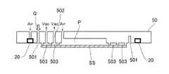
次に、図3と図4を参照しながら型保持部50について説明する。図3は、第1実施形態に係るヘッド52を下(−Z方向)から見た平面図である。型保持部50は、型SSを陽圧で湾曲させる凹部Pと、型SSを真空吸着で保持する複数の真空吸着溝503と、隙間Hへ気体Qを供給する複数の気体供給孔501と、壁部20を有する。真空吸着溝503は真空吸着孔502を通してヘッド52外部の負圧発生装置へと連通し、壁部20と凹部Pは圧力制御部60へと連通している。 Next, the
図4は、第1実施形態に係る型保持部50の断面図である。型保持部50の凹部Pと複数の真空吸着溝503は型SSを中心軸対称に湾曲させるために同心円状に形成されていることが好ましい。壁部20は、複数の真空吸着溝503の外周側に配置され、例えば、外力を与えると変形する弾性体であり、中空で環状の弾性ゴム材や金属バネ材、樹脂材を含む。この壁部20は、例えば、型保持部50の型SS保持面に形成された円形の外周形状の溝に埋め込まれている。壁部20は、複数部材によって構成してもよく、又は、領域毎に分割してもよい。 FIG. 4 is a cross-sectional view of the
壁部20は、圧力制御部60から圧力を供給されて、その中空内部を陽圧にするとZ方向、つまり、圧力制御部60は、壁部を変形させる変形部としても機能する。基板保持部10の方向へ向かって膨張(または変形)し、型保持部50の表面から湾曲して突き出て、その内部を負圧にすると型保持部50の表面から凹む動作を行う。即ち、壁部20は、型保持部50の表面から数ミリ程突き出すことで対向する基板保持部10と接して壁を形成し、型SSとインプリント材MLとの間の隙間Hを含む密閉空間形成することができる。ただし、壁部20と基板保持部10の接触によりパーティクルが生じるおそれがある場合は、圧力制御部60により壁部20の突出し量を精密にコントロールして壁部20と基板保持部10の表面が非接触となるように僅かに隙間を空けてもよい。 When the
また、壁部20が型保持部50の表面から湾曲して突き出している状態、すなわち、壁部20が壁を形成している状態からさらに壁部20の内部に圧力を加える。すると、壁部20は、XY方向、言い換えると、基板Wの表面に沿う方向に向かって膨張(または変形)し、壁部20によって形成された空間を狭めるように駆動することができる。 Further, pressure is further applied to the inside of the
気体供給孔501は、気体供給部61と連通し、型SSの外周に沿って壁部20と最外の真空吸着溝503との間に複数配設され、隙間Hへ向けて気体を噴出する。使用する気体Qは型SSと基板Wとの間に気泡が残留しにくいように拡散性が高い物性、あるいは、インプリント材MLに対して溶解性が高い物性を持つ気体であり、例えば、ヘリウムや二酸化炭素、アルゴンなどの気体を用いる。複数の気体供給孔501のうち、一部の孔は圧力制御部60と連通し、気体Qによって押し出される隙間H内部の空気を気体供給孔501の一部の孔から排気して隙間H内部を負圧にしてもよい。本実施形態では、型保持部50の壁部20と最外の真空吸着溝503との間に気体供給孔501を設けて隙間H内部に気体Qを供給している。しかし、壁部20の外周部あるいは型保持部50の外部、例えば、基板保持部10やヘッド52から隙間Hへ気体Qを供給することで壁部20を駆動してもよい。 A plurality of gas supply holes 501 communicate with the
ここで、このような型保持部50の構成により、図5を参照しながら隙間Hへ気体Qを充填する処理について説明する。図5は、第1実施形態に係る隙間Hへ気体Qを充填する処理を説明する図である。まず、型保持部50で型SSを保持し凹部Pに陽圧を供給して型SSを湾曲させながら型保持部50を降下させて型SSをインプリント材MLへ漸近させる。そして、気体供給孔501から気体Qをインプリント材MLへ向けて噴きつける(図5(A)の状態)。 Here, a process of filling the gap H with the gas Q with reference to FIG. 5 will be described with such a configuration of the
同時に圧力制御部60から壁部20へ圧力供給して、壁部20を型保持部50表面から突出させるように駆動する。即ち、壁部20をZ方向に膨張させる。本実施形態においては、これを第1の加圧という。第1加圧は、気体Qが隙間Hに供給されている期間において実行される。湾曲する型SSに従って基板Wの外周へ押し出されようとする気体Qをこの第1の加圧によって膨張した壁部20で遮蔽し、壁部20で囲まれた空間A内に気体Qを閉じ込める(図5(B)の状態)。ここで、空間Aは、壁部20によって囲まれた隙間Hを含む空間である。 At the same time, pressure is supplied from the
さらに、型保持部50を降下させて型SSをインプリント材MLへ接触させてインプリント材MLを基板Wの中心から外側に向けて押し拡げていきながら、圧力制御部60からさらに壁部20へ圧力を供給する。そして、壁部20を、XY方向に膨張させるように駆動する(図5(C)の状態)。つまり、第1加圧によって形成された空間Aをさらに狭める。こうすることで、壁部20で囲まれた空間Aの容積が小さくなり、空間A内における気体Qの濃度を高める効果が得られる。なお、壁部20が膨張する方向は、空間Aを狭めるため、XY方向のうち少なくとも基板Wの中心方向である必要がある。 Further, the
その後、壁部20内部を負圧にして型保持部50の表面から凹ませ、壁部20を基板保持部10から引き離し、型SSを基板Wの凹凸に倣わせる。そして、照射部70から基板W全面へ向けて光UVを照射し、インプリント材MLを硬化させる(図5(D)の状態)。硬化中も隙間Hを一定の気体濃度で維持するためにある程度の密閉状態にしておきたい場合は、圧力制御部60により壁部20の突出量を精密にコントロールして壁部20と基板保持部10の表面が非接触となるように僅かに隙間を空けてもよい。 After that, the inside of the
以上の気体充填方法が基板Wの処理毎に行われることによって、最小限の気体供給量で、型SSと基板全面に塗布されたインプリント材MLとの間の空気を即座に高濃度気体へ置換することができる。 By performing the above gas filling method for each treatment of the substrate W, the air between the mold SS and the imprint material ML coated on the entire surface of the substrate is immediately converted to a high-concentration gas with the minimum amount of gas supplied. Can be replaced.
次に、図6を参照ながら、本実施形態に係る成形処理について説明する。図6は、第1実施形態に係る成形処理の一例を示すフロー図である。このフロー図で示す各動作(ステップ)は、制御部80よって実行されうる。 Next, the molding process according to the present embodiment will be described with reference to FIG. FIG. 6 is a flow chart showing an example of the molding process according to the first embodiment. Each operation (step) shown in this flow chart can be executed by the
S601において、制御部80は、型保持部50を降下させて型SSをインプリント材MLへ漸近させる。そして、S602において、気体供給孔501から気体(ガス)Qをインプリント材MLへ向けて噴射させ、隙間Hに気体Qを充填させる。S602と並行して、S603において、第1加圧を実行する。具体的には、圧力制御部60から壁部20へ圧力供給して、壁部20を型保持部50表面から突出させる。即ち、圧力制御部60は、壁部20をZ方向に膨張させるように駆動する。なお、壁部20を最初から突出させた状態で構成し、第1加圧を省略しても良い。 In S601, the
次に、S604において、制御部80は、隙間Hにおける気体Qの濃度が閾値以上なっているか否かを判定する。この判定においては、例えば、予め隙間Hにおける気体Qの濃度が閾値以上となる時間を設定しておき、経過時間によって判定しても良い。また、気体Qの濃度を計測するための計測器を設け、この計測結果に基づいて判定しても良い。S604において、気体Qの濃度が閾値以上でない場合(No)は、濃度が閾値以上となるまで、S602を継続する。一方、気体Qの濃度が閾値以上である場合(Yes)は、S605およびS606に処理を進める。 Next, in S604, the
S605において、制御部80は、型保持部50をさらに降下させて型SSを基板上のインプリント材MLへ接触させる。また、S605と並行して、S606において、第2加圧を実行する。具体的には、圧力制御部60から、さらに壁部20へ圧力を供給して壁部20を、XY方向に膨張させるように駆動する。なお、第2加圧をせずに単に壁部20を基板に垂直な方向に移動させるように駆動することによって図4(C)のように壁部20を基板中心に向けて変形させても良い。第2加圧は、少なくとも隙間Hへの気体Qの供給が開始された後に実行される。 In S605, the
その後、S607において、制御部80は、照射部70からインプリント材MLに対して光UVを照射させ、インプリント材MLを硬化させる。そして、S608において、硬化したインプリント材MLから、型SSを剥離(離型)させて、処理を終了する。 After that, in S607, the
本実施形態よれば、成形処理に用いられる気体の供給量を低減することができ、延いては、成形処理における欠陥の発生を低減することが可能となる。 According to this embodiment, the supply amount of the gas used in the molding process can be reduced, and by extension, the occurrence of defects in the molding process can be reduced.
なお、本実施形態においては、気体Qが供給される隙間Hを含む空間を壁部20によって狭めるために、壁部20を、外力を与えると変形する弾性体としたが、これに限られるものではない。例えば、壁部20が弾性体でない場合であっても、壁部20に少なくともZ方向およびXY方向に駆動可能なアクチュエータなどの駆動部を設けることで、同様の処理を行うことができる。この場合、図6に示すフロー図のS603において壁部20を基板保持部10の方向へ向かって下降させ、S606において、壁部20を基板Wの中心方向へ向けて移動させる。 In the present embodiment, in order to narrow the space including the gap H to which the gas Q is supplied by the
<第2実施形態>
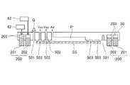
図7は、第2実施形態に係る型保持部50の断面図である。上述の実施形態と同様の部分については説明を省略する。第2実施形態において、壁部200は、複数の壁、外側壁201と、内側壁202と、を含む。外側壁201は、隙間Hを囲むように配置され、内側壁202は、外側壁201の内側に沿うように配置される。なお、本実施形態の外側壁201と、内側壁202は弾性体に限らず、金属等であっても良い。また、基板保持部10と接触した際のパーティクルの発生を低減するため、基板保持部10と接触する部分のみを弾性体とするなど、一部のみを弾性体としても良い。<Second Embodiment>
FIG. 7 is a cross-sectional view of the
外側壁201と、内側壁202とは、それぞれアクチュエータ203を備え、アクチュエータ203により基板保持部10へ向けて下降(駆動)することができる。アクチュエータ203は、例えば、圧電素子、発熱素子、リニアモータ、超音波モータ、空圧シリンダ等であり、電源供給部又は圧力供給部62からエネルギーが供給されて外側壁201および内側壁202をそれぞれ駆動する。 The
第2実施形態係る成形処理について説明する。本実施形態の成形処理は、図6に示すフロー図のS603において外側壁201を基板保持部10の方向へ向かって下降させる。そして、S606において、内側壁202を基板保持部10の方向へ向かって下降するように駆動させる。ガスが充填された状態で内側壁202を外側壁201で囲まれた空間内に配置することにより、外側壁201で囲まれた空間Aを、内側壁202によって基板の中心に向かって狭めることができ、第1実施形態と同等の効果を得ることができる。よって、内側壁202を下降させる駆動は、少なくとも隙間Hへの気体Qの供給が開始された後に実行される。 The molding process according to the second embodiment will be described. In the molding process of the present embodiment, the
<第3実施形態>
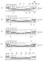
図8は、第3実施形態に係る隙間Hへ気体Qを充填する処理を説明する図である。上述の実施形態と同様の部分については説明を省略する。第3実施形態において、壁部20は、複数の壁、内側壁802と、外側壁801を含む。<Third Embodiment>
FIG. 8 is a diagram illustrating a process of filling the gap H according to the third embodiment with the gas Q. The description of the same parts as those in the above-described embodiment will be omitted. In the third embodiment, the
外側壁801と内側壁802は、例えば、それぞれ外力を与えると変形する弾性体であり、中空で環状の弾性ゴム材や金属バネ材、樹脂材を含む。なお、内側壁802のみを弾性体とし、外側壁801は、例えば、金属等弾性体でなくてもよい。 The
本実施形態では、まず、型保持部50で型SSを保持し凹部Pに陽圧を供給して型SSを湾曲させながら型保持部50を降下させて型SSをインプリント材MLへ漸近させる。そして、気体供給孔501から気体Qをインプリント材MLへ向けて噴きつける(図8(A)の状態)。 In the present embodiment, first, the mold SS is held by the
同時に圧力制御部60から外側壁801へ圧力供給して外側壁801を型保持部50表面から突出させる。湾曲する型SSに従って基板Wの外周へ押し出されようとする気体Qをこの外側壁801で遮蔽し、外側壁801で囲まれた空間A内に気体Qを閉じ込める(図8(B)の状態)。 At the same time, pressure is supplied from the
さらに、型保持部50を降下させて型SSをインプリント材MLへ接触させてインプリント材MLを基板Wの中心から外側に向けて押し拡げていきながら、圧力制御部60から内側壁802へ圧力供給する。そして、内側壁802を型保持部50表面から突出させる(図8(C)の状態)。こうすることで、内側壁802で囲まれた空間Aの容積が小さくなり、閉じ込められた気体Qの濃度を高める効果が得られる。 Further, the
隙間Hを気体Qで充填する際、隙間Hの空間内で気体濃度に差が生じる場合がある。基板Wの外周領域に対して基板Wの中心領域は気体供給孔501から遠いため、気体濃度が比較的上がりにくい。そこで、より好適には、基板Wの中心方向へ向けて少なくとも内側壁802を膨張(または変形)させるとよい(図8(D)の状態)。具体的には、例えば、型保持部50をさらに下降させ、内側壁802と基板保持部10を完全に接触させて、駆動部51による押し付け力で内側壁802を基板Wの中心方向へ向けて変形させる。こうすることで、閉じ込めた隙間Hの気体Qを基板Wの中心方向へ押し出し、基板W中心領域の気体Qの濃度を上げる効果が得られる。 When the gap H is filled with the gas Q, there may be a difference in gas concentration in the space of the gap H. Since the central region of the substrate W is far from the
その後、外側壁801および内側壁802の内部を負圧にして型保持部50の表面から凹ませ、外側壁801および内側壁802を基板保持部10から引き離し、型SSを基板Wの凹凸に倣わせる。そして、照射部70から基板W全面へ向けて光UVを照射し、インプリント材MLを硬化させる(図8(E)の状態)。硬化中も隙間Hを一定の気体濃度で維持するためにある程度の密閉状態にしておきたい場合は、圧力制御部60により内側壁802の突出量を精密にコントロールして内側壁802と基板保持部10の表面が非接触となるように僅かに隙間を空けてもよい。 After that, the inside of the
本実施形態によれば、基板W中心領域の気体Q濃度をより上げることが可能となり、欠陥の発生をより低減することが可能となる。 According to this embodiment, the gas Q concentration in the central region of the substrate W can be further increased, and the occurrence of defects can be further reduced.
<第4実施形態>
図9は、第4実施形態に係る基板保持部10の断面図である。上述の実施形態と同様の部分については説明を省略する。上述の実施形態においては、壁部を型保持部側に設けたが、壁部を基板保持部10側にも配設してもよい。<Fourth Embodiment>
FIG. 9 is a cross-sectional view of the
壁部90は、ステージ1に構成された圧力制御部60から圧力供給されて、その中空内部を陽圧にすると膨張し、基板保持部10の表面から湾曲して突き出し、その内部を負圧にすると基板保持部10の表面から凹む動作を行う。壁部90は基板保持部10の表面から数ミリ程突き出すことで対向の型保持部50、あるいは、型保持部50側の壁部と接して壁を形成し、型SSとインプリント材MLとの間の隙間Hを含む密閉空間形成することができる。 The
本実施形態によれば、第1実施形態と同等の効果が得られる。なお、図9では、壁部90は複数の壁を含む構成としているが、これに限られるものではない。つまり、第1実施形態と同様の壁部を基板保持部10側に設けても良い。 According to this embodiment, the same effect as that of the first embodiment can be obtained. In FIG. 9, the
<物品の製造方法>
物品としてのデバイス(半導体デバイス、磁気記憶媒体、液晶表示素子等)の製造方法について説明する。かかる製造方法は、成形装置を用いて基板(ウエハ、ガラスプレート、フィルム状基板等)の表面に平坦化処理をする工程を含む。基板は母材単体であるものに限らず多層構造のものを含む。<Manufacturing method of goods>
A method for manufacturing a device as an article (semiconductor device, magnetic storage medium, liquid crystal display element, etc.) will be described. Such a manufacturing method includes a step of flattening the surface of a substrate (wafer, glass plate, film-like substrate, etc.) using a molding apparatus. The substrate is not limited to a single base material, but includes a multilayer structure.
かかる製造方法は、上記平坦化処理工程の前または後に、基板を処理する工程を更に含む。例えば処理工程は、平坦化処理がされた層の上にパターンを形成する工程と、当該パターンの残膜を除去する工程と、を含みうる。また、当該パターンをマスクとして基板をエッチングする工程と、基板からチップを切り出す工程(ダイシング)と、フレームにチップを配置して電気的に接続する工程(ボンディング)、樹脂で封止をする工程(モールド)といった周知の工程を含みうる。本実施形態における物品の製造方法は、従来に比べて、物品の性能、品質、生産性及び生産コストの少なくとも1つにおいて有利である。 Such a manufacturing method further includes a step of treating the substrate before or after the flattening treatment step. For example, the treatment step may include a step of forming a pattern on the flattened layer and a step of removing the residual film of the pattern. In addition, the process of etching the substrate using the pattern as a mask, the process of cutting out the chip from the substrate (dicing), the process of arranging the chip on the frame and electrically connecting it (bonding), and the process of sealing with resin (separation) It can include well-known steps such as molding). The method for producing a good in the present embodiment is advantageous in at least one of the performance, quality, productivity and production cost of the good as compared with the conventional method.
<その他の実施形態>
以上、本発明の好ましい実施形態について説明したが、本発明はこれらの実施形態に限定されないことはいうまでもなく、その要旨の範囲内で種々の変形及び変更が可能である。上述の実施形態では、デバイス用途のパターンが形成されていない型を用いてインプリント材を成形する平坦化装置を説明した。しかしながら、本発明は、平坦化装置に限られるものではない。例えば、デバイス用途の凹凸パターンが形成された型を用いてインプリント材を成形する装置にも適用できる。このような装置はインプリント装置やパターン転写装置と呼ばれることがあり、「型」は、マスク、モールド、テンプレートと呼ばれることがある。また、本発明は、型を複製するためのレプリカ装置にも適用されうる。本明細書において、「基板」は、転写先のブランク状態の型を含む。このような型は、ブランクマスク、ブランクテンプレートと呼ばれることがある。<Other Embodiments>
Although the preferred embodiments of the present invention have been described above, it goes without saying that the present invention is not limited to these embodiments, and various modifications and modifications can be made within the scope of the gist thereof. In the above-described embodiment, a flattening device for molding an imprint material using a mold in which a pattern for device use is not formed has been described. However, the present invention is not limited to the flattening device. For example, it can be applied to an apparatus for molding an imprint material using a mold having a concavo-convex pattern for device use. Such devices are sometimes referred to as imprinting devices or pattern transfer devices, and "molds" are sometimes referred to as masks, molds, and templates. The present invention can also be applied to replica devices for replicating molds. As used herein, the term "substrate" includes a blank mold of the transfer destination. Such types are sometimes referred to as blank masks, blank templates.
上述の実施形態の成形装置をインプリント装置に適用する場合、特に、基板の全面上のインプリント材に一括でパターンを押印転写する装置において有利である。このような一括転写では、基板上のショット(フィールド)領域毎に押印する装置に比べて型と基板の間の空隙容積が大きく上述の実施形態と同じ効果を得やすいためである。しかしながら、一括転写に限定されるものではなく、例えば、複数のショット領域を同時に転写する装置においても有効である。 When the molding apparatus of the above-described embodiment is applied to an imprinting apparatus, it is particularly advantageous in an apparatus for imprinting and transferring a pattern to an imprinting material on the entire surface of a substrate. This is because in such batch transfer, the void volume between the mold and the substrate is larger than that of the apparatus for imprinting each shot (field) region on the substrate, and the same effect as that of the above-described embodiment can be easily obtained. However, the present invention is not limited to batch transfer, and is also effective in, for example, an apparatus for simultaneously transferring a plurality of shot regions.
上述の実施形態の成形装置をインプリント装置に適用する場合のデバイスの製造方法は、成形装置を用いて基板(ウエハ、ガラスプレート、フィルム状基板等)の表面に型のパターンを転写する工程を含む。かかる製造方法は、上記パターン転写工程の前または後に、基板を処理する工程を更に含む。例えば処理工程は、パターンの残膜を除去する工程を含みうる。
When the molding apparatus of the above embodiment is applied to an imprinting apparatus, the device manufacturing method involves transferring a mold pattern to the surface of a substrate (wafer, glass plate, film-like substrate, etc.) using the molding apparatus. Including. Such a manufacturing method further includes a step of processing the substrate before or after the pattern transfer step. For example, the treatment step may include a step of removing the residual film of the pattern.
Claims (13)
Translated fromJapanese前記基板を保持する基板保持部と、
前記型を保持する型保持部と、
前記型保持部に保持された前記型と、前記基板保持部に保持された前記基板との間の隙間に気体を供給する気体供給部と、
前記気体が供給される前記隙間を囲むように配置される壁部と、
前記壁部を制御する制御部と、を有し、
前記制御部は、前記壁部によって囲まれた空間を、前記基板の表面に沿う方向において、前記基板の中心に向かって狭めるように、前記壁部の少なくとも一部を前記基板に垂直な方向に駆動させることを特徴とする成形装置。A molding device that molds a composition on a substrate using a mold.
A substrate holding portion that holds the substrate and
A mold holder that holds the mold and
A gas supply unit that supplies gas to a gap between the mold held by the mold holding unit and the substrate held by the substrate holding unit, and a gas supply unit.
A wall portion arranged so as to surround the gap to which the gas is supplied,
It has a control unit that controls the wall portion, and has
The control unit makes at least a part of the wall portion perpendicular to the substrate so as to narrow the space surrounded by the wall portion toward the center of the substrate in a direction along the surface of the substrate. A molding device characterized by being driven.
前記第1壁は、前記隙間を囲むように配置され、
前記第1壁によって囲まれた空間内に前記気体供給部によって前記気体の供給が開始された後において、前記第1壁の内側に前記第2壁を配置するよう前記壁部を駆動することにより、前記空間を前記基板の中心に向かって狭めることを特徴とする請求項1乃至3のいずれか1項に記載の成形装置。The wall portion includes a first wall and a second wall.
The first wall is arranged so as to surround the gap.
After the gas supply unit starts supplying the gas into the space surrounded by the first wall, the wall unit is driven so as to arrange the second wall inside the first wall. The molding apparatus according to any one of claims 1 to 3, wherein the space is narrowed toward the center of the substrate.
前記基板を保持する基板保持工程と、
前記型を保持する型保持工程と、
保持された前記型と、保持された前記基板との間の隙間に気体を供給する気体供給工程と、
前記気体が供給される前記隙間を囲むように壁部を配置するとともに、前記壁部によって囲まれた空間を、前記基板の表面に沿う方向において、前記基板の中心に向かって狭めるように、前記壁部の少なくとも一部を駆動する工程を有することを特徴とする成形方法。A molding method for molding a composition on a substrate using a mold.
A substrate holding step for holding the substrate and
A mold holding step for holding the mold and
A gas supply step of supplying gas to the gap between the held mold and the held substrate, and
The wall portion is arranged so as to surround the gap to which the gas is supplied, and the space surrounded by the wall portion is narrowed toward the center of the substrate in a direction along the surface of the substrate. A molding method comprising a step of driving at least a part of a wall portion.
前記工程で組成物が形成された前記基板を処理する工程と、
処理された前記基板から物品を製造する工程と、を含む、
ことを特徴とする物品の製造方法。
A step of molding a composition on a substrate using the molding apparatus according to any one of claims 1 to 12.
A step of processing the substrate on which the composition was formed in the step, and a step of processing the substrate.
A step of manufacturing an article from the treated substrate, and the like.
A method of manufacturing an article, characterized in that.
Priority Applications (1)
| Application Number | Priority Date | Filing Date | Title |
|---|---|---|---|
| JP2019184784AJP2021061328A (en) | 2019-10-07 | 2019-10-07 | Device and method for molding composition on substrate using mold, and method for manufacturing article |
Applications Claiming Priority (1)
| Application Number | Priority Date | Filing Date | Title |
|---|---|---|---|
| JP2019184784AJP2021061328A (en) | 2019-10-07 | 2019-10-07 | Device and method for molding composition on substrate using mold, and method for manufacturing article |
Publications (1)
| Publication Number | Publication Date |
|---|---|
| JP2021061328Atrue JP2021061328A (en) | 2021-04-15 |
Family
ID=75381189
Family Applications (1)
| Application Number | Title | Priority Date | Filing Date |
|---|---|---|---|
| JP2019184784APendingJP2021061328A (en) | 2019-10-07 | 2019-10-07 | Device and method for molding composition on substrate using mold, and method for manufacturing article |
Country Status (1)
| Country | Link |
|---|---|
| JP (1) | JP2021061328A (en) |
Citations (7)
| Publication number | Priority date | Publication date | Assignee | Title |
|---|---|---|---|---|
| JP2007178557A (en)* | 2005-12-27 | 2007-07-12 | Orc Mfg Co Ltd | Exposure apparatus |
| US20090056575A1 (en)* | 2007-08-31 | 2009-03-05 | Bartman Jon A | Pattern transfer apparatus |
| JP2010517300A (en)* | 2007-01-29 | 2010-05-20 | ヒューレット−パッカード デベロップメント カンパニー エル.ピー. | Contact lithography apparatus and method using substrate deformation |
| JP2014069550A (en)* | 2012-10-01 | 2014-04-21 | Idemitsu Unitech Co Ltd | Transfer molding device |
| JP2015056548A (en)* | 2013-09-12 | 2015-03-23 | 大日本印刷株式会社 | Imprint apparatus and imprint method |
| JP2016054232A (en)* | 2014-09-04 | 2016-04-14 | キヤノン株式会社 | Imprint device |
| WO2016092700A1 (en)* | 2014-12-12 | 2016-06-16 | キヤノン株式会社 | Substrate holding apparatus, lithography apparatus, and article manufacturing method |
- 2019
- 2019-10-07JPJP2019184784Apatent/JP2021061328A/enactivePending
Patent Citations (7)
| Publication number | Priority date | Publication date | Assignee | Title |
|---|---|---|---|---|
| JP2007178557A (en)* | 2005-12-27 | 2007-07-12 | Orc Mfg Co Ltd | Exposure apparatus |
| JP2010517300A (en)* | 2007-01-29 | 2010-05-20 | ヒューレット−パッカード デベロップメント カンパニー エル.ピー. | Contact lithography apparatus and method using substrate deformation |
| US20090056575A1 (en)* | 2007-08-31 | 2009-03-05 | Bartman Jon A | Pattern transfer apparatus |
| JP2014069550A (en)* | 2012-10-01 | 2014-04-21 | Idemitsu Unitech Co Ltd | Transfer molding device |
| JP2015056548A (en)* | 2013-09-12 | 2015-03-23 | 大日本印刷株式会社 | Imprint apparatus and imprint method |
| JP2016054232A (en)* | 2014-09-04 | 2016-04-14 | キヤノン株式会社 | Imprint device |
| WO2016092700A1 (en)* | 2014-12-12 | 2016-06-16 | キヤノン株式会社 | Substrate holding apparatus, lithography apparatus, and article manufacturing method |
Similar Documents
| Publication | Publication Date | Title |
|---|---|---|
| JP5930622B2 (en) | Imprint apparatus and article manufacturing method | |
| JP4533358B2 (en) | Imprint method, imprint apparatus and chip manufacturing method | |
| KR102580550B1 (en) | Planarized layer forming apparatus, and method of manufacturing article | |
| JP7033994B2 (en) | Molding equipment and manufacturing method of articles | |
| JP5822597B2 (en) | Imprint apparatus and article manufacturing method using the same | |
| JP2017112230A (en) | Imprint apparatus and article manufacturing method | |
| JP2012099789A (en) | Imprint device and manufacturing method of article | |
| JP2019216143A (en) | Molding apparatus for molding composition on substrate using mold and manufacturing method for article | |
| JP2021061328A (en) | Device and method for molding composition on substrate using mold, and method for manufacturing article | |
| JP2017126723A (en) | Imprint apparatus and article manufacturing method | |
| JP6304921B2 (en) | Imprint method, imprint apparatus, and article manufacturing method using the same | |
| JP2023156163A (en) | Imprint device, imprint method, and method for manufacturing article | |
| KR102744794B1 (en) | Imprint apparatus, imprint method, and article manufacturing method | |
| JP2019046819A (en) | Molding apparatus for molding composition on substrate using mold and method for manufacturing article | |
| JP2018029101A (en) | Imprint apparatus and article manufacturing method | |
| JP2021005679A (en) | Molding device, and article manufacturing method using molding device | |
| US12285904B2 (en) | Imprint apparatus, imprint method, and article manufacturing method | |
| JP2024092690A (en) | IMPRINT APPARATUS, IMPRINT METHOD AND METHOD FOR MANUFACTURING ARTICLE | |
| JP2018206815A (en) | Mold, imprint apparatus, and manufacturing method of article | |
| JP2024090241A (en) | Imprint method, imprint apparatus, and article manufacturing method | |
| KR20250033965A (en) | Imprint apparatus, imprint method, information processing apparatus and article manufacturing method | |
| JP2024104626A (en) | IMPRINT METHOD, IMPRINT DEVICE, DECISION METHOD, INFORMATION PROCESSING DEVICE, AND METHOD FOR PRODUCING ARTICLE | |
| JP2025147800A (en) | Imprinting apparatus, imprinting method, program, and article manufacturing method | |
| US20210023768A1 (en) | Imprint apparatus, imprint method, and article manufacturing method | |
| JP2024171087A (en) | IMPRINT APPARATUS, IMPRINT METHOD, AND PRODUCTION METHOD OF ARTICLE |
Legal Events
| Date | Code | Title | Description |
|---|---|---|---|
| A621 | Written request for application examination | Free format text:JAPANESE INTERMEDIATE CODE: A621 Effective date:20220914 | |
| A977 | Report on retrieval | Free format text:JAPANESE INTERMEDIATE CODE: A971007 Effective date:20230426 | |
| A131 | Notification of reasons for refusal | Free format text:JAPANESE INTERMEDIATE CODE: A131 Effective date:20230509 | |
| A02 | Decision of refusal | Free format text:JAPANESE INTERMEDIATE CODE: A02 Effective date:20231031 |