JP2021061285A - Magnetic wall mounting article - Google Patents
Magnetic wall mounting articleDownload PDFInfo
- Publication number
- JP2021061285A JP2021061285AJP2019183269AJP2019183269AJP2021061285AJP 2021061285 AJP2021061285 AJP 2021061285AJP 2019183269 AJP2019183269 AJP 2019183269AJP 2019183269 AJP2019183269 AJP 2019183269AJP 2021061285 AJP2021061285 AJP 2021061285A
- Authority
- JP
- Japan
- Prior art keywords
- magnet sheet
- magnetic wall
- magnetic
- magnet
- article
- Prior art date
- Legal status (The legal status is an assumption and is not a legal conclusion. Google has not performed a legal analysis and makes no representation as to the accuracy of the status listed.)
- Granted
Links
Images


Landscapes
- Supports Or Holders For Household Use (AREA)
Abstract
Description
Translated fromJapanese 本発明は、磁性壁取付け物品に関する。
より詳しくは、壁面部の材料に磁性材料を含ませ、磁石が吸着し得るように構成した磁性壁に、磁力を利用して着脱自在に取り付けることのできる物品に関する。The present invention relates to a magnetic wall-mounted article.
More specifically, the present invention relates to an article that can be detachably attached to a magnetic wall formed by impregnating a wall surface material with a magnetic material so that a magnet can be attracted to the wall surface by using magnetic force.
上述のような磁性壁取付け物品として、例えば下記特許文献1,2に記載のL字棚がある。
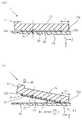
本出願における図19は、従来のL字棚90を示す側面図であり、図19(a)はL字棚90を磁性壁94に取り付けた状態を示し、図19(b)と図19(c)はそれぞれL字棚90を磁性壁94から取り外しているときの状態を示す。As the magnetic wall-mounted article as described above, for example, there is an L-shaped shelf described in
FIG. 19 in the present application is a side view showing a conventional L-
図19(a)に示すように、L字棚90は、載置板91と背面板92と磁石シート93を備える。
磁石シート93は、粘結剤となる合成樹脂材と、硬磁性物質からなる磁性粉とを主成分とした混合体に着磁を施した可撓性の磁石体であり、背面板92の裏面に接着剤で固着されている。L字棚90は、磁石シート93により磁性壁94に磁気吸着させた状態で、載置板91上に物95を載せることができるようになっている。As shown in FIG. 19A, the L-
The
このようなL字棚90は、耐荷重に応じて、吸着力の強い磁石シート、すなわち比較的広面積で且つ厚い磁石シートが用いられる。例えば縦10cm×横20cmを超えるとともに、厚さが2mm程度の磁石シートになると、壁面から手前方向に引っ張っても容易に取り外すことができないことが多い。 For such an L-
そのような場合は、載置板91上に載った物95をおろした後、両手で載置板91の左右(図では紙面に対して奥側と手前側)を掴んだ状態で、図19(b)のように、載置板91の先端付近に上向きの力F1を加える。
そして、てこの原理を利用し、磁石シート93の磁着面の上端縁96を支軸として時計回り方向に回動させる形で、磁石シート93の磁着面の下方側から引き剥がすようにして取り外す。或いは、図19(c)のように、載置板91の先端付近に下向きの力F0を加え、磁石シート93の磁着面側の下端縁97を支軸として反時計回り方向に回動させる形で、磁石シート93の磁着面の上側から引き剥がすようにして取り外す。In such a case, after lowering the
Then, using the principle of leverage, the
ところで、磁石シート93は、主成分である粘結剤と磁性粉との重量比として、例えば粘結剤15パーセントに対し、磁性粉85パーセント程度のものが広く使われ、磁性粉の基本色である黒色を呈するとともに、可撓性とはいえ硬度も高い。 By the way, as for the
また、L字棚90の磁石シート93では、取り外しに際して回動の支軸となる上端縁96または下端縁97は、断面が直角状になっており、回動時に磁性壁94からの反作用で集中的に大きな力が加わる。
さらに、力の強い人と弱い人では、力の入れどころが異なり、例えば力の強い人では、最終段階で壁面から一気に引き剥がすことができるが、力の弱い人では、壁面に若干擦りつけるようにして引き剥がす。このような場合、磁石シート93の支軸となる部分に傷がついたり摩耗が生じたりすることで、そこに含まれる磁性粉が磁性壁94の壁面に付着し黒い跡を残すことがある。Further, in the
Furthermore, the force is applied differently between a strong person and a weak person. For example, a strong person can peel it off the wall surface at a stretch at the final stage, but a weak person should rub it against the wall surface. And peel it off. In such a case, the portion serving as the support shaft of the
本発明は、上記実情に鑑みてなされたものであって、磁性壁から取外す際に、磁石シートに含まれる磁性粉で磁性壁が汚れることを防止できる磁性壁取付け物品を提供することを課題とする。 The present invention has been made in view of the above circumstances, and an object of the present invention is to provide a magnetic wall-mounted article capable of preventing the magnetic wall from being contaminated with magnetic powder contained in the magnet sheet when it is removed from the magnetic wall. To do.
本発明は、上記の課題を解決するために次のような手段をとる。
なお、以下に記す手段の説明では、後述する発明を実施するための形態の説明及び図面で使用した符号の一部を参考のために括弧書きで付記するが、本発明の構成要素はこれに限定されるものではない。The present invention takes the following measures to solve the above problems.
In the description of the means described below, the description of the mode for carrying out the invention described later and a part of the reference numerals used in the drawings are added in parentheses for reference, but the constituent elements of the present invention are added thereto. It is not limited.
本発明の一の態様では、磁力によって磁性壁(70)に着脱自在に取り付けることのできる磁性壁取付け物品(1)であって、磁性壁(70)への取付け対象となる物品本体(10)と、物品本体(10)に固着して設けられる磁石シート(20)とを備え、磁石シート(20)の磁着面(22)における少なくとも端縁(22a)を含む領域に、薄膜からなる保護膜層(30)を設けたことを特徴とする。 In one aspect of the present invention, the magnetic wall-mounted article (1) that can be detachably attached to the magnetic wall (70) by magnetic force, and the article body (10) to be attached to the magnetic wall (70). And a magnet sheet (20) provided fixed to the article main body (10), and a protection made of a thin film in a region including at least an edge (22a) on the magnetically attached surface (22) of the magnet sheet (20). It is characterized in that a film layer (30) is provided.
本態様によると、磁石シート(20)の磁着面(22)の全面が磁性壁(70)に貼着されている状態の磁性壁取付け物品(1)を、磁着面(22)の端縁(22a)を支軸として回動させて取り外すにあたり、回動させるときの支軸となる磁着面(22)における端縁(22a)が保護膜層(30)により保護されるので、端縁(22a)に局所的な力が集中的に作用した場合であっても、磁石シート(20)の摩耗が抑制されるとともに磁性壁(70)に磁石シート(20)の磁性粉が付着することが防止される。 According to this aspect, the magnetic wall mounting article (1) in a state where the entire surface of the magnetic surface (22) of the magnet sheet (20) is attached to the magnetic wall (70) is attached to the edge of the magnetic surface (22). When the edge (22a) is rotated around the support shaft to be removed, the end edge (22a) on the magnetically attached surface (22), which is the support shaft when the edge (22a) is rotated, is protected by the protective film layer (30). Even when a local force acts intensively on the edge (22a), the wear of the magnet sheet (20) is suppressed and the magnetic powder of the magnet sheet (20) adheres to the magnetic wall (70). Is prevented.
本発明の他の態様では、磁石シート(20)は、物品本体(10)の端縁(12a)と磁石シート(20)における磁着面(22)の端縁(22a)とを含む平面(P0)と、磁石シート(20)における磁着面(22)とのなす角度(φ)が20°よりも小さくなるように、物品本体(10)からセットバックした位置に設けられる。 In another aspect of the present invention, the magnet sheet (20) is a flat surface (22a) including an edge (12a) of the article body (10) and an edge (22a) of a magnetized surface (22) on the magnet sheet (20). The magnet sheet (20) is provided at a position set back from the article main body (10) so that the angle (φ) formed by the magnetized surface (22) on the magnet sheet (20) is smaller than 20 °.
本態様によると、磁石シート(20)の磁着面(22)の全面が磁性壁(70)に貼着されている状態の磁性壁取付け物品(1)を、磁着面(22)の端縁(22a)を支軸として回動させて取り外すにあたり、回動させている途中で、物品本体(10)の端縁(12a)が磁性壁(70)に当接し、以降はこの端縁(12a)を支軸として回動させることが可能となる。つまり回動の支軸の変遷が可能となる。
これにより、最初に回動させるときの支軸となる磁着面(22)の端縁(22a)に局所的な力が集中的に作用することが防止でき、磁石シート(20)の摩耗が抑制されるとともに磁性壁(70)に磁石シート(20)の磁性粉が付着することが防止される。According to this aspect, the magnetic wall mounting article (1) in a state where the entire surface of the magnetically attached surface (22) of the magnet sheet (20) is attached to the magnetic wall (70) is attached to the edge of the magnetically attached surface (22). When removing by rotating the edge (22a) as a support shaft, the edge (12a) of the article body (10) comes into contact with the magnetic wall (70) during the rotation, and thereafter, this edge (22a) It is possible to rotate with 12a) as a support shaft. That is, the rotation support shaft can be changed.
As a result, it is possible to prevent a local force from acting intensively on the edge (22a) of the magnetically attached surface (22), which is a support shaft when the magnet sheet (20) is first rotated, and the magnet sheet (20) is worn. It is suppressed and the magnetic powder of the magnet sheet (20) is prevented from adhering to the magnetic wall (70).
本発明の他の態様では、物品本体(1)は、磁石シート(20)の磁着面(22)が物品本体(1)と面一または物品本体(1)から突出するように磁石シート(20)を埋設する凹部を備える。 In another aspect of the present invention, the article body (1) is such that the magnetized surface (22) of the magnet sheet (20) is flush with the article body (1) or projects from the article body (1). A recess for burying 20) is provided.
本態様によると、物品本体(1)からの磁石シート(20)の突出距離を微小にできるため、磁石シート(20)の厚みを変えることなく角度(φ)、つまりセットバック距離(L1)に対する物品本体(1)からの磁石シート(20)の突出距離(D1)の逆正接(図5(b)参照)を微小にできる。これにより、支軸の変遷による効果を一層高めることができる。 According to this aspect, since the protrusion distance of the magnet sheet (20) from the article body (1) can be made small, the angle (φ), that is, the setback distance (L1) can be obtained without changing the thickness of the magnet sheet (20). The reverse tangent (see FIG. 5B) of the protrusion distance (D1) of the magnet sheet (20) from the article body (1) can be made minute. As a result, the effect of the transition of the support shaft can be further enhanced.
本発明の他の態様では、図6のように、磁石シート(20)は、弾性体からなるクッション材(40)を介して物品本体(10)に固着される。 In another aspect of the present invention, as shown in FIG. 6, the magnet sheet (20) is fixed to the article body (10) via a cushion material (40) made of an elastic body.
本態様によると、磁石シート(20)の磁着面(22)の全面が磁性壁(70)に貼着されている状態の磁性壁取付け物品(1)を、磁着面(22)の端縁(22a)を支軸として回動させて取り外すにあたり、磁性壁取付け物品(1)にこれを回動させるための力を加えたとき、クッション材(40)は、次のように弾性変形する。
すなわち図7(b)のように、磁石シート(20)における磁着面(22)の端縁(22a)側では、物品本体(10)の固着面(13)から磁石シート(20)の磁着面(22)にかけて縮む形で弾性変形する。これにより、支軸となる磁石シート(20)の端縁(22a)が磁性壁(70)から受ける力が吸収緩和される。
これとは反対に、磁石シート(20)の下端縁(22c)側では、磁着面(22)から物品本体(10)の固着面(13)にかけて伸びる形で弾性変形する。これにより、磁石シート(20)を磁性壁(70)から引き剥がそうという力が加わる。
磁石シート(20)は可撓性なので、これら2つの作用が相乗することにより、図7(c)のように、上端縁(22a)から下端縁(22c)にかけて固着面(23)の側に凹型となるように撓んだ形で引き剥がされていく。
これにより、最初に回動させるときの支軸となる磁着面(22)の上端縁(22a)に局所的な力が集中的に作用することが防止でき、磁石シート(20)の摩耗が抑制されるとともに磁性壁(70)に磁石シート(20)の磁性粉が付着することが防止される。
つまり磁石シート(20)は、クッション材(40)の弾性作用を受けながら剥離がなされるため、支軸となる上端縁(22a)にかかる集中的な力が吸収される。According to this aspect, the magnetic wall mounting article (1) in a state where the entire surface of the magnetically attached surface (22) of the magnet sheet (20) is attached to the magnetic wall (70) is attached to the edge of the magnetically attached surface (22). When the magnetic wall-mounted article (1) is subjected to a force for rotating the edge (22a) when it is rotated and removed by using the edge (22a) as a support shaft, the cushion material (40) elastically deforms as follows. ..
That is, as shown in FIG. 7 (b), on the edge (22a) side of the magnetically attached surface (22) of the magnet sheet (20), the magnetism of the magnet sheet (20) from the fixing surface (13) of the article body (10). It elastically deforms in a form that shrinks toward the landing surface (22). As a result, the force received by the edge (22a) of the magnet sheet (20) serving as the support shaft from the magnetic wall (70) is absorbed and relaxed.
On the contrary, on the lower end edge (22c) side of the magnet sheet (20), the magnet sheet (20) is elastically deformed so as to extend from the magnetically attached surface (22) to the fixing surface (13) of the article body (10). As a result, a force is applied to peel the magnet sheet (20) from the magnetic wall (70).
Since the magnet sheet (20) is flexible, these two actions synergistically move to the side of the fixing surface (23) from the upper end edge (22a) to the lower end edge (22c) as shown in FIG. 7 (c). It is peeled off in a bent shape so that it becomes a concave shape.
As a result, it is possible to prevent a local force from acting intensively on the upper end edge (22a) of the magnetically attached surface (22), which is a support shaft when the magnet sheet (22) is first rotated, and the magnet sheet (20) is worn. It is suppressed and the magnetic powder of the magnet sheet (20) is prevented from adhering to the magnetic wall (70).
That is, since the magnet sheet (20) is peeled off while receiving the elastic action of the cushion material (40), the concentrated force applied to the upper end edge (22a) serving as the support shaft is absorbed.
本発明の他の態様では、図11から図14のように、磁石シート(50)は、扁平な略直方体形状であり、少なくとも2つの非対角のコーナー部(55)の間に、物品本体(10)への固着面(53)の側から磁性壁(70)への磁着面(52)にかけて、厚み方向に直交する平面で切ったときの切断面面積が漸次減少するテーパ状の側面(56)が形成される。 In another aspect of the invention, as shown in FIGS. 11-14, the magnet sheet (50) has a flat, substantially rectangular parallelepiped shape, with the article body between at least two off-diagonal corners (55). A tapered side surface in which the cut surface area gradually decreases when cut in a plane orthogonal to the thickness direction from the side of the surface (53) fixed to (10) to the magnetic surface (52) to the magnetic wall (70). (56) is formed.
本態様によると、テーパ状の側面(56)は、磁石シート(50)の磁着面(52)と鈍角をなして接続される形となる。このときの接続箇所は、磁着面(52)の上端縁(52a)であり、回動させるときの支軸となる。
この時、支軸が鈍角となることにより磁性壁(70)から局所的な力が集中的に作用することが防止でき、磁石シート(50)の摩耗が抑制されるとともに磁性壁(70)に磁石シート(50)の磁性粉が付着することが防止される。
また、各端縁部には、テーパ状の側面(56)がない場合に対して、図14のように空間(S0)が形成されるため、取り外しの最終段階で、磁石シート(50)はこの空間(S0)により磁性壁(70)から逃げる形となり、磁石シート(50)の磁性粉により磁性壁(70)が汚れることが防止される。According to this aspect, the tapered side surface (56) is connected to the magnetized surface (52) of the magnet sheet (50) at an obtuse angle. The connection point at this time is the upper end edge (52a) of the magnetized surface (52), which serves as a support shaft when rotating.
At this time, since the support shaft has an obtuse angle, it is possible to prevent a local force from acting intensively from the magnetic wall (70), and the wear of the magnet sheet (50) is suppressed and the magnetic wall (70) is affected. The magnetic powder of the magnet sheet (50) is prevented from adhering.
Further, since a space (S0) is formed at each end edge portion as shown in FIG. 14 when there is no tapered side surface (56), the magnet sheet (50) is removed at the final stage of removal. This space (S0) allows the magnetic wall (70) to escape from the magnetic wall (70), and the magnetic powder of the magnet sheet (50) prevents the magnetic wall (70) from becoming dirty.
本発明の他の態様では、磁石シート(50)は、少なくとも2つの非対角のコーナー部(55)に、物品本体(10)への固着面(53)の側から磁性壁(70)への磁着面(52)にかけて、厚み方向に直交する平面で切ったときの切断面面積が漸次減少するテーパ状のコーナー面(57)を形成してある。 In another aspect of the invention, the magnet sheet (50) is at least at two orthogonal corners (55) from the side of the surface (53) to the article body (10) to the magnetic wall (70). A tapered corner surface (57) is formed over the magnetized surface (52) of the above, in which the area of the cut surface when cut in a plane orthogonal to the thickness direction gradually decreases.
本態様によると、上記コーナー部(55)には、テーパ状のコーナー面(57)がない場合に対して、図14のように空間(S1)が形成されるため、取り外しの最終段階で、磁石シート(50)はこの空間(S1)により磁性壁(70)から逃げる形となり、磁石シート(50)の磁性粉により磁性壁(70)が汚れることが防止できる。 According to this aspect, a space (S1) is formed in the corner portion (55) as shown in FIG. 14 when there is no tapered corner surface (57). The space (S1) allows the magnet sheet (50) to escape from the magnetic wall (70), and the magnetic powder of the magnet sheet (50) can prevent the magnetic wall (70) from becoming dirty.
本発明の他の態様では、図17のように、磁石シート(20)を、それぞれ平面視領域が等サイズとなる複数の磁石シート片(61〜65)に分割してなる。 In another aspect of the present invention, as shown in FIG. 17, the magnet sheet (20) is divided into a plurality of magnet sheet pieces (61 to 65) having the same size in the plan view region.
本態様によると、磁石シート片(61〜65)の構成要素単位で交換可能なため、磁石シート全体を交換せずに、その摩耗や傷に対応できる。また、物品本体のサイズに応じて、磁石シート片を組み合わせることができるので、物品本体のサイズに合わせた磁石シートを製作する必要がなくなる。 According to this aspect, since the magnet sheet pieces (61 to 65) can be replaced in units of components, it is possible to deal with wear and scratches without replacing the entire magnet sheet. Further, since the magnet sheet pieces can be combined according to the size of the article body, it is not necessary to manufacture the magnet sheet according to the size of the article body.
本発明によると、磁性壁から取外す際に、磁石シートに含まれる磁性粉で磁性壁が汚れることを防止できる磁性壁取付け物品が提供される。 According to the present invention, there is provided a magnetic wall-mounted article capable of preventing the magnetic wall from being contaminated with magnetic powder contained in the magnet sheet when it is removed from the magnetic wall.
〔第1実施形態〕
以下、添付図面を参照しながら、本発明の第1実施形態を説明する。なお、添付図面に図示した部材などの縮尺や角度は、必ずしも実物と一致するものではなく、適宜明示しやすい大きさに調整している。[First Embodiment]
Hereinafter, the first embodiment of the present invention will be described with reference to the accompanying drawings. The scales and angles of the members shown in the attached drawings do not always match the actual ones, and are adjusted to a size that is easy to clearly indicate.
図1は本発明に係る第1実施形態のL字棚1を示す斜視図、図2は図1のe−e線矢視図、図3はL字棚1の一部側断面図である。なお後述の各図を含めたこれらの図において、直交座標系の3軸をXYZとし、磁性壁70はXY平面に垂直で且つZX平面に平行であるとする。 FIG. 1 is a perspective view showing the L-shaped
図1に示すように、L字棚1は、本体部10と磁石シート20を備える。
本体部10は、木材または合成樹脂を材質とした長方形状の剛体からなる二枚の板を、側面視がL字型となるように接合させた構成とされ、載置板11と背面板12を備える。
載置板11は、物を載せるための載せ台として機能する。
背面板12は、取付対象である磁性壁70への対向部となる部分であり、その裏面は磁石シート20を固着させることのできる全面フラットな固着面13となっている。As shown in FIG. 1, the L-shaped
The
The mounting
The
磁石シート20は、図1,2,3に示すように、背面板12の面領域よりも小さな領域サイズとされた扁平の直方体形状を呈する可撓性の磁石体であり、背面板12の固着面(裏面)13へ固着させるための固着面23と、磁性壁70へ磁着させるための磁着面22とを備える。 As shown in FIGS. 1, 2, and 3, the
磁石シート20は、例えば粘結剤となる合成樹脂と、硬磁性物質からなる磁性粉との混合体に着磁を施したシート状の磁石体を、背面板12の面領域よりも小さな領域サイズに切断して得られる。磁石シート20の厚さは1.5mm〜5mm程度とされる。
なお、磁石シート20の磁着面22には、一方向に沿ってN極およびS極が交互に等間隔ピッチで並ぶ縞状の多極着磁パターンが形成されている。そのピッチ間隔は1.5mm〜3mm程度とされる。磁石シート20の磁着面22は、全面にわたって保護膜層30で被覆されている。The
The
保護膜層30は、PP(ポリプロピレン)、PET(ポリエチレンテレフタレート)、PVC(ポリ塩化ビニール)などの熱可塑性樹脂を基本材質とした薄幕層である。
この薄幕層は、例えば厚さ15μ〜500μの薄膜フィルムを、磁石シート20の磁着面22に接着剤で貼着することによって形成される。
貼着は、例えば専用のラミネータ装置によりなされるが、手作業で行うことも可能である。
なお、保護膜層30は、無色透明、有色透明、或いは着色のいずれであってもよい。また、薄膜フィルムを貼着するのでなく、溶融した液状の熱可塑性樹脂を塗装し乾燥固化させることで形成することもできる。The
This thin curtain layer is formed by, for example, attaching a thin film having a thickness of 15 μ to 500 μ to the magnetically bonded
The attachment is performed by, for example, a dedicated laminator device, but it can also be performed manually.
The
このように磁着面22が保護膜層30で被覆された磁石シート20は、その固着面23に塗布した接着剤を介して、図2に示すように、背面板12の裏面(固着面13)にセットバックさせた状態で固着される。
すなわち、背面板12の各端縁12a,12b,12c,12dから距離L1のところに磁石シート20の固着面23の端縁23a,23b,23c,23dが位置する。As shown in FIG. 2, the
That is, the
背面板12への磁石シート20の固着は、次の〔条件式1〕を満たすように設定されることが好ましい。
〔条件式1〕φ=arctan(D1/L1)として、0°<φ<20°The sticking of the
[Conditional expression 1] As φ = arctan (D1 / L1), 0 ° <φ <20 °
ここで、条件式(1)の各諸元は次のとおりである。
L1:背面板12の端縁から、対応する磁石シート20における固着面22の端縁までの水平距離
D1:背面板12の固着面13から磁石シート20における磁着面22までの厚み方向距離Here, the specifications of the conditional expression (1) are as follows.
L1: Horizontal distance from the edge of the
すなわち磁石シート20は、背面板12の端縁12aと磁石シート20における磁着面22の端縁22aとを含む平面P0と、磁石シート20における磁着面22とのなす角度φが20°よりも小さくなるように、背面板12からセットバックした位置に取り付けられている。端縁12b,12c,12dからの磁石シート20の取付位置についても同形態とされる。 That is, the
次に、図4,5を用いて、磁性壁70に取り付けられたL字棚1の取り外し方について説明する。図4は磁性壁70に取り付けられたL字棚1を取り外すときの状態を時系列的に示す斜視図であり、図4(a)はL字棚1が磁性壁70に取り付けられた状態を示し、図4(b)はL字棚1を磁性壁70から取り外しているときの状態を示す。
図5はL字棚1を磁性壁70から取り外すときの磁石シート20と磁性壁70との当接状態を時系列的に示す側断面図である。なお、図5(a)は図4(a)に対応し、図5(b)は図4(b)に対応している。Next, how to remove the L-shaped
FIG. 5 is a side sectional view showing a contact state between the
L字棚1を取り外すには種々の手法が考えられるが、ここでは磁石シート20の磁着面22の上端縁22aを支軸として回動させる形の取り外し方について説明する。 Various methods can be considered for removing the L-shaped
ここで磁性壁70は、シート状軟質磁性体、例えば、鉄板、または鉄粉をエラストマーに練り込んだシートを壁下地に接着剤で貼着し、その上に表装材(不図示)を積層したものからなり、種々のマグネット製品を磁気吸着可能な非磁石型の壁である。
なお、このタイプとは異なり、シート状磁石を壁下地に接着剤で貼着し、その上に表装材を積層したものからなる磁石型の壁としてもよい。Here, for the
In addition, unlike this type, a magnet-type wall may be formed in which a sheet-shaped magnet is attached to a wall base with an adhesive and a surface material is laminated on the sheet-shaped magnet.
磁性壁70に取り付けられたL字棚1を取り外すとき、作業者は、載置板11上に載った物をおろした後、両手で載置板11の左右を掴んだ状態で、図4(a)のように、載置板11の先端付近に上向きの力F1を加える。 When removing the L-shaped
力F1の加え初めの段階では、磁性壁70への磁石シート20の吸着力に打ち勝つことができないため、図5(a)のように、磁石シート20は磁性壁70に全磁着面22が磁気吸着されている。 At the initial stage of applying the force F1, the attractive force of the
力F1を更に加え続けていくと、磁石シート20は、下端縁22c側から剥離が進み、図5(b)のように、上端縁22a側の一部を除く磁着面22が、ほぼ同時に剥離する。それと同時にL字棚1は、上端縁22aを支点として、図中時計回り方向Wに回動する。 When the force F1 is further applied, the
ここで、磁着面22は、保護膜層30により被覆されているため、上端縁22aの直角部分が直接に磁性壁70に当接することが防止される。これにより、磁石シート20の摩耗が抑制されるとともに磁性壁70に磁石シート20の磁性粉が付着することが防止される。 Here, since the magnetically bonded
また、磁石シート20は、背面板12の裏面(固着面13)領域にセットバックさせた状態で固着されている。このため、回動が始まった直後に、背面板12の端縁12aが磁性壁70に当接し、以降はこの端縁12aを支軸として回動させることができる。
つまり回動の支軸の変遷がなされる。その結果、磁石シート20の上端縁22aに磁性壁70から局所的な力が集中的に作用することが防止でき、この点からも、磁性壁70に磁石シート20の磁性粉が付着することが防止される。
ここで、0°<φ<20°とした理由は次のとおりである。すなわちφの値が20°以上となった場合は、端縁22aを除いた磁着面22の剥離が既に終了してしまっている可能性が高く、この状態を排除するためである。
なお、保護膜層30を設けていない状態の磁石シート20を、壁面からの角度を傾斜させて擦りつける実験を試みたところ、5°前後から壁面に汚れが付着することがわかったが、本実施形態では保護膜層30を設けているため、5°を超えても壁面に汚れが付着することはない。Further, the
That is, the rotation support shaft is changed. As a result, it is possible to prevent a local force from acting intensively from the
Here, the reason why 0 ° <φ <20 ° is set is as follows. That is, when the value of φ is 20 ° or more, it is highly possible that the peeling of the magnetically bonded
An experiment was conducted in which the
また、上述のL字棚1では、背面板12の裏面はフラット面とされ、このフラット面に磁石シート20を固着させていたが、背面板12の裏面に凹部を設け、この凹部内に磁石シート20の非磁着面側の一部または全部を埋設する形としてもよい。
この構成では、背面板12のフラット面からの磁石シート20の突出距離を微小にできるため、磁石シート20の厚みを変えることなく角度φを微小にできる。これにより、支軸の変遷による効果を一層高めることができる。
なお、磁石シート20の全部を埋設した場合は、磁気保持力を確保するため、磁石シート20の磁着面は背面板12のフラット面と面一にする必要がある。Further, in the above-mentioned L-shaped
In this configuration, since the protrusion distance of the
When the
〔第2実施形態〕
次に、本発明の第2実施形態を説明する。
図6は本発明に係る第2実施形態のL字棚2の一部側断面図である。図6において、第1実施形態のL字棚1と同一の構成要素については、同一の符号を付しそれらの説明を省略する。[Second Embodiment]
Next, a second embodiment of the present invention will be described.
FIG. 6 is a partial side sectional view of the L-shaped
図6に示すように、L字棚2は、第1実施形態のL字棚1に対して、クッション材40を備える。
クッション材40は、磁石シート20と同じ平面視サイズを有する直方体状の弾性体である。その材質は、発泡スチレン、発泡ウレタン、スポンジなどからなり、一方の面は、磁石シート20の固着面23に接着剤を介して固定される。他方の面は、背面板12の固着面13に接着剤を介して固定される。
また、クッション材40の弾性率は、磁石シート20の弾性率よりも小さい。つまりクッション材40は、磁石シート20よりも軟らかいものとされる。As shown in FIG. 6, the L-shaped
The
Further, the elastic modulus of the
次に、図7,8を用いて、L字棚2の取外し方について説明する。
図7,8は、L字棚2を磁性壁70から取り外すときの磁石シート20と磁性壁70との当接状態を時系列的に示す側断面図である。Next, how to remove the L-shaped
7 and 8 are side sectional views showing the contact state between the
L字棚2の取外しは、基本的にL字棚1の取外しと同様な要領で行う。すなわち、作業者は、両手で載置板11の左右を掴んだ状態で、載置板11の先端付近に上向きの力F1(図4参照)を加える。 The removal of the L-shaped
力F1の加え初めの段階では、クッション材40が図7(a)の状態から図7(b)のように弾性変形するとともに、本体部10は磁石シート20の上端縁22aを支軸として、図中時計回り方向Wに回動を始める。
すなわち、磁石シート20の上端縁22aの側(Z軸方向側)では、クッション材40は、本体部10から磁石シート20にかけて縮む形で弾性変形する。
一方、磁石シート20の下端縁22cの側では、磁石シート20から本体部10にかけて伸びる形で弾性変形する。このとき磁石シート20の磁着面22には、磁石シート20を磁性壁70から引き剥がそうとする剥離トルクが作用する。
但し、この剥離トルクの大きさは、回動の支軸となる上端縁22aからの距離に比例するが、図7(b)の段階ではまだ十分ではなく、磁石シート20の剥離はなされない。At the initial stage of applying the force F1, the
That is, on the side of the
On the other hand, on the side of the
However, the magnitude of this peeling torque is proportional to the distance from the
力F1を更に加えていくと、磁石シート20は、図7(c)のように、上端縁22aから下端縁22cにかけて、固着面23の側に凹型に湾曲するように撓む形で剥離されていく。
この現象は、クッション材40とともに磁石シート20が弾性体であり、クッション材40の弾性率が磁石シート20の弾性率よりも小さいものとされるために起こると考えられる。磁石シート20は、クッション材40の弾性作用を受けながら剥離がなされるため、支軸となる上端縁22aにかかる集中的な力が吸収される。When the force F1 is further applied, the
It is considered that this phenomenon occurs because the
ここで、磁石シート20は背面板12の裏面(固着面13)領域にセットバックさせた状態で固着されるため、第1実施形態と同様に、本体部10が回動していく途中段階で、図8(a)のように、背面板12の上端縁12aが磁性壁70に当接し、以降はこの上端縁12aを支軸として回動させることができる。
その結果、磁石シート20の上端縁22aに磁性壁70から局所的な力が集中的に作用することが防止でき、磁性壁70の壁面に磁石シート20の磁性粉が付着することが防止される。
また、磁石シート20の上端縁22aは保護膜層30により保護されていることにより、磁石シート20の上端縁22aの直角部分が直接に磁性壁70に当接することが防止される。このため、磁石シート20の摩耗が抑制されるとともに磁性壁70に磁石シート20の磁性粉が付着することが防止される。Here, since the
As a result, it is possible to prevent a local force from acting intensively from the
Further, since the
その後、図8(b)のように、磁石シート20と磁性壁70との接触箇所が上端縁22aだけとなったとき、図8(c)のように、本体部10に磁性壁70の壁面に垂直な力F2を加えて手前に引き離す。 After that, when the contact point between the
〔第3実施形態〕
次に、本発明の第3実施形態を説明する。
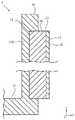
図9は本発明に係る第3実施形態のL字棚3の一部側断面図である。
なお、図9において、第2実施形態のL字棚2と同一の構成要素については、同一の符号を付しそれらの説明を省略する。[Third Embodiment]
Next, a third embodiment of the present invention will be described.
FIG. 9 is a partial side sectional view of the L-shaped
In FIG. 9, the same components as the L-shaped
第2実施形態のL字棚2では、背面板12の裏面は完全なフラット面とされ、このフラット面に、クッション材40を介して磁石シート20を固着させていたが、L字棚3では、背面板12に代えて、裏面に凹部19を設けた背面板120を備え、凹部19内にクッション材40の一部を埋設する形としている。
なお、凹部19の周囲には枠部18を形成しており、その枠部18の表面はフラット面となっている。In the L-shaped
A
次に、図10を用いて、L字棚3の取外し方について説明する。
図10は、L字棚3を磁性壁70から取り外すときの磁石シート20と磁性壁70との当接状態を時系列的に示す側断面図である。Next, how to remove the L-shaped
FIG. 10 is a side sectional view showing a contact state between the
作業者は、まず、磁性壁70に取り付けられたL字棚3に対し、両手で載置板11の左右を掴んだ状態で、図10(a)のように、載置板11を磁性壁70の壁面に向けて垂直な力F3を加えて押し込む。これによりクッション材40は、図10(b)のように一様に収縮し、枠部18が磁性壁70に当接する。この状態では、磁石シート20の磁着面22と枠部18の底面とは面一となっている。
次に、両手で載置板11の左右を掴んで押し込んだ状態で、第1,2実施形態と同じように、載置板11の先端付近に上向きの力F1を加える(図4参照)。First, the operator holds the left and right sides of the mounting
Next, in a state where the left and right sides of the mounting
上記したように、磁石シート20の磁着面22と枠部18の底面(フラット面)とは面一となっている。
従って、第1,2実施形態と異なり、初めから、背面板120の上端縁120aが磁性壁70に当接している。このため、力F1を更に加えていくと、初めから上端縁120aを支軸として回動させることができる。
その結果、第1,2実施形態に比べて、磁石シート20の上端縁22aに磁性壁70から局所的な力が集中的に作用することが防止できる効果が、より一層顕著となる。
つまり磁性壁70の壁面に磁石シート20の磁性粉が付着することが防止される効果がより一層顕著となる。As described above, the
Therefore, unlike the first and second embodiments, the
As a result, as compared with the first and second embodiments, the effect of preventing the local force from the
That is, the effect of preventing the magnetic powder of the
〔第4実施形態〕
次に、本発明の第4実施形態を説明する。
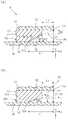
図11は本発明に係る第4実施形態のL字棚4の一部側断面図、図12は第4実施形態のL字棚4の一部断面背面図である。
図13は磁石シート50の要部を示す図であり、図13(a)は磁石シート50のコーナー部55の平面図、図13(b)は図13(a)のf−f線断面図、図13(c)は図13(a)のg−g線断面図を示す。
図14はL字棚4に固着された磁石シート50を模式的に示す斜視図である。
図15はL字棚4の要部を模式的に示す側断面図であり、図15(a)は後述の条件式(4)を満たす例を示し、図15(b)は条件式(4)を満たさない例を示す。[Fourth Embodiment]
Next, a fourth embodiment of the present invention will be described.
FIG. 11 is a partial cross-sectional rear view of the L-shaped
13 is a view showing a main part of the
FIG. 14 is a perspective view schematically showing a
FIG. 15 is a side sectional view schematically showing a main part of the L-shaped
図11,12に示すように、L字棚4は、第1実施形態のL字棚1の磁石シート20に代えて、磁石シート50と保護膜層300を備える。それ以外は、L字棚1と同一の構成であり、同一の構成要素については説明を省略する。 As shown in FIGS. 11 and 12, the L-shaped
磁石シート50は、図11〜13に示すように、背面板12の面領域よりも小さな領域サイズとされた扁平の略四角錐台形状を呈する可撓性の磁石体であり、背面板12の固着面(裏面)13に固着させるための固着面53と、磁性壁70へ磁着させるための磁着面52とを備える。固着面53の側には、扁平の直方体状の台座51を備える。
磁石シート50では、四隅におけるコーナー部55のうち、辺方向に隣合うコーナー部の間、つまり非対角のコーナー部の間には、図13(b)に示すように、固着面53の側から磁着面52にかけて、厚み方向に直交する平面(図ではXZ平面)で切ったときの切断面面積が漸次減少するテーパ状の側面56(傾斜角度θ2)が形成されている。As shown in FIGS. 11 to 13, the
In the
なお、各コーナー部55には、図13(c)に示すように、固着面53の側から磁着面52にかけて、厚み方向に直交する平面で切ったときの切断面面積が漸次減少するテーパ状のコーナー面57(傾斜角度θ3)が形成されている。
また、テーパ状のコーナー面57の磁着面52側における端縁は、図13(a)に示すように、所定の曲率で形成されたアール部58を備えた形状になっている。なお、製造コスト低減のため、曲率を有さずに直線的な形状としてもよい。ここで、傾斜角度θ3は傾斜角度θ2よりも小さく設定されている。これによってコーナー部55には、より一層広い空間が確保できる。As shown in FIG. 13C, each
Further, as shown in FIG. 13A, the edge of the tapered
磁石シート50における上記形状は、例えば第1実施形態で示した磁石シート20に対し、ヤスリやカッターナイフなどで各側面56、コーナー面57およびアール部58を切削加工して成形される。或いは金型を用いて成形される。このような形状に成形する際、一般には、台座51を残しておく。ここで磁石シート50の磁着面52は、保護膜層300で被覆されている。保護膜層300は、溶融状態の熱可塑性樹脂を塗装し乾燥固化させることで形成することが好ましい。 The shape of the
このように、底部に台座51を備えるとともに扁平な四角錐台の四隅にテーパ状のコーナー面57を設け、さらに磁着面52の端部にアール加工を施した形状の磁石シート50は、その固着面53に塗布した接着剤を介して、背面板12の裏面(固着面13)にセットバックさせた状態で固着される。
すなわち背面板12の各端縁12a,12b,12c,12dから距離L2のところに磁石シート50の固着面53の端縁53a,53b,53c,53dが位置する。
また、背面板12の各端縁12a,12b,12c,12dから距離L1のところに磁石シート50の磁着面52の端縁52a,52b,52c,52dが位置する。As described above, the
That is, the
Further, the
距離L1,L2は、次の〔条件式2〕〜〔条件式4〕を満たすように設定される。
〔条件式2〕θ1=arctan(D1/L1)
〔条件式3〕θ2=arctan{(D1−D2)/(L1−L2)}
〔条件式4〕θ2>θ1The distances L1 and L2 are set so as to satisfy the following [conditional expression 2] to [conditional expression 4].
[Conditional expression 2] θ1 = arctan (D1 / L1)
[Conditional expression 3] θ2 = arctan {(D1-D2) / (L1-L2)}
[Conditional expression 4] θ2> θ1
ここで、上記式の各諸元は次のとおりである(図15参照)。
L1:背面板12の端縁から、対応する磁石シート50における磁着面52の端縁までのZ軸方向距離
L2:背面板12の端縁から、対応する磁石シート50における固着面53の端縁までのZ軸方向距離
θ1:背面板12の裏面の端縁と磁石シート50における磁着面52の端縁とを含む平面P1と、磁石シート50における磁着面52とのなす角度 θ2:磁着面52からの磁石シート50におけるテーパ状の側面56の傾斜角度
D1:背面板12の固着面13から測った台座51の厚み
D2:背面板12の固着面13から測った磁石シート50における磁着面52までの厚みHere, the specifications of the above equation are as follows (see FIG. 15).
L1: Z-axis direction distance from the edge of the
次に、図16を用いて、第4実施形態のL字棚4の取外し方について説明する。
図16は、第4実施形態のL字棚4を磁性壁70から取り外すときの磁石シート50と磁性壁70との当接状態を時系列的に示す側断面図である。
なお、図16では紙面の都合上、背面板12と磁性壁70を横向きとし、保護膜層300を省略して描いている。Next, how to remove the L-shaped
FIG. 16 is a side sectional view showing a contact state between the
In FIG. 16, due to space limitations, the
L字棚4を磁性壁70から取り外すとき、作業者は、実施形態1の場合と同様に、図4、図16(a)のように、両手で載置板11の左右を掴んだ状態で載置板11の先端付近に上向きの力F1を加える。
そして、図16(b)のように、磁石シート50の磁着面52の上端縁52aを支軸として時計回り方向Wに回動させる形で、磁着面52の下方側(図16では左側)から引き剥がしていく。
図16(c)のように回動角がθ1となった時点で、背面板12の端縁12aと磁性壁70とが当接した後、支軸は背面板12の端縁12aとなる。
この場合に、磁石シート50では、θ2>θ1と設定することにより、端縁12aが磁性壁70に当接する前に、台座51が磁性壁70に当接してしまう(図15(b)参照 同図で破線T1を磁性壁70の壁面と考えたとき台座51がこれに当接してしまう)ことが回避でき、磁石シート50以外への支軸の変遷が可能となる。When removing the L-shaped
Then, as shown in FIG. 16B, the
When the rotation angle becomes θ1 as shown in FIG. 16C, the
In this case, in the
その結果、磁石シート50に磁性壁70からの局所的な力が集中的に作用することが防止でき、磁性壁70の壁面に磁石シート50の磁性粉が付着することが防止される。 As a result, it is possible to prevent the local force from the
ここで、テーパ状の側面56は、磁石シート50の磁着面52と鈍角をなして接続される形となる。このときの接続箇所は、磁着面52の上端縁52aであり、回動させるときの支軸となる。磁着面52は保護膜層300で被覆されているとともに、上端縁52aが鈍角をなして接続されることにより、磁石シート50が磁性壁70から受ける集中荷重が、第1実施形態よりも緩和され、摩耗が更に緩和される。
これにより、磁石シート50の磁粉により磁性壁70が汚れることが防止される。Here, the tapered
This prevents the
また、各コーナー部55には、テーパ状のコーナー面57(傾斜角度θ3)が形成されている。これにより各コーナー部55には、磁性壁70との間に空間S1(図14参照)が形成されることになる。 Further, each
L字棚の取り外しの最終段階では、磁石シート50と磁性壁70との当接部を上下左右の少なくとも一方向に無意識のうちにすべらせるような形で取り外すことがしばしばあるが、そのような場合であっても、磁石シート50はこの空間S1により磁性壁70から逃げる形となるため、磁性壁70が汚れることが防止できる。 In the final stage of removing the L-shaped shelf, it is often the case that the contact portion between the
また、L字棚4を磁性壁70に取り付けるときは、載置板11が水平になるように磁性壁70に磁気吸着させるが、定規や水準器等の計測器具を用いずに取り付けた場合、水平から若干ずれて取り付けられてしまうことが多い。
その場合、取付位置の修正を行う。取付位置の修正は、取り外しのときと同様な要領で、磁石シート50の上端縁または下端縁を支軸として回動させる。そして、L字棚4を完全に取り外さない状態で、つまり磁性壁70の面内でこの支軸を上下左右の少なくとも一方向に微小距離移動させることで調整する。
このときも、磁石シート50に含まれる磁性粉が磁性壁70の壁面に付着し黒い跡を残すことがあるが、第4実施形態の上記構成により、取付位置の修正を行うときも、取外しのときと同様な理由で磁性壁70が汚れることが防止できる。
ここで、傾斜角度θ3を傾斜角度θ2よりも小さく設定することで、より一層広い空間S1を形成することができるようになる。Further, when the L-shaped
In that case, the mounting position is corrected. The mounting position is modified by rotating the
At this time as well, the magnetic powder contained in the
Here, by setting the inclination angle θ3 to be smaller than the inclination angle θ2, a wider space S1 can be formed.
また、テーパ状のコーナー面57の磁着面52側における端縁は、アール部28を備えた形状になっている。このため、磁性壁70に磁着面52を磁着させたとき又は取外しの際に、角部が直接に磁性壁70当接することがないので集中荷重を受けることが防止される。 Further, the edge of the tapered
〔第5実施形態〕
図17は第5実施形態のL字棚5の要部を示す平面図である。第5実施形態のL字棚5は、第1実施形態のL字棚1の磁石シート20に代えて、磁石シート群60を備える。[Fifth Embodiment]
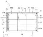
FIG. 17 is a plan view showing a main part of the L-shaped
磁石シート群60は、図2に示す磁石シート20を、それぞれ平面視領域が等サイズとなるように9分割したもので、2つの第1コーナー用の磁石シート片61と、2つの第2コーナー用の磁石シート片62と、2つの第1周辺用の磁石シート片63と、2つの第2周辺用の磁石シート片64と、1つの中央用の磁石シート片65とを備える。 The
磁石シート片61は、長方形における一対の長辺部と短辺部に、それぞれテーパ状の側面561を有し、且つそれらの間のコーナー部にテーパ状のコーナー面571を備える。磁石シート片62は、長方形における磁石シート片61とは異なる一対の長辺部と短辺部に、それぞれテーパ状の側面562を有し、且つそれらの間のコーナー部にテーパ状のコーナー面572を備える。磁石シート片63は、長方形における一つの短辺部にテーパ状の側面563を有し、その他の辺の側面やコーナー部はテーパ状になっていない。磁石シート片64は、長方形における一つの長辺部にテーパ状の側面564を有し、その他の辺の側面やコーナー部はテーパ状になっていない。磁石シート片65は、いずれの辺の側面やコーナー部もテーパ状になっていない。つまり扁平直方体状である。 The
L字棚5によると、外観としては、第4実施形態のL字棚4と同じであり、その作用効果を奏する。しかし、磁石シート片の構成要素単位での交換ができる点で、第1から4各実施形態の磁石シート20,50とは異なり、部分的な摩耗や傷が生じた場合に、その磁石シート片のみを交換すればよく、磁石シート全体を交換せずに対応できる。また、このような磁石シート片63,64をそれぞれ予め複2数枚用意しておくことにより、棚本体のサイズに合わせた磁石シートを製作する必要がなくなる。例えば、図18のように、より大サイズの背面板121に対しては、セットバックの基本位置は変えずに、隣り合う磁石シート片の間に間隙を設けて配置することで、1枚物の磁石シートに近い吸着および汚れ防止性能を期待できる。 According to the L-shaped
また、例えば縦4枚×横6枚の磁石シート片の配置とする場合、磁石シート片61,62を固着させる枚数は変える必要がなく、磁石シート片63,64,65についてのみ枚数を増やせばよい。更に、磁石シート片63,64を共に正方形形状とすれば、両磁石シート片63,64を区別する必要がないので、準備しておく磁石シート片の種類を削減できる。 Further, for example, in the case of arranging 4 vertical × 6 horizontal magnet sheet pieces, it is not necessary to change the number of
以上、本発明の実施の形態について説明を行ったが、上に開示した実施の形態は、あくまで例示であって、本発明の範囲はこの実施の形態に限定されるものではない。本発明の範囲は、特許請求の範囲の記載によって示され、更に特許請求の範囲と均等の意味及び範囲内でのすべての変更を含むことが意図される。 Although the embodiments of the present invention have been described above, the embodiments disclosed above are merely examples, and the scope of the present invention is not limited to these embodiments. The scope of the present invention is indicated by the description of the scope of claims, and is intended to include all modifications within the meaning and scope equivalent to the scope of claims.
すなわち本発明は、上述した各実施形態以外にも、各種に変形して実施することができる。例えば、各実施形態で、磁石シート20,50の磁着面は、それぞれ全面にわたって保護膜層30,300で被覆されているが、磁石シート20,50の磁着面における少なくとも端縁を含む領域を被覆する形態としてもよい。保護膜層30,300が保護したい部分は、汚れの発生源に最もなりやすい回動支軸となる磁石シートの端縁であるからである。このためセロハンテープで磁石シートの各端縁を被覆するような構成でもよい。また、壁面との静止摩擦係数を上げるため保護膜層30,300に粘性材を貼着したり含有させたりしてもよい。また、磁石シート20,50として片面多極着磁のものを示したが、両面多極着磁としてもよい。 That is, the present invention can be implemented in various modifications other than the above-described embodiments. For example, in each embodiment, the magnetically coated surfaces of the
また第4実施形態において、テーパ状の側面56を必ずしも4辺全てについて設けることなく、1辺だけについて設けるようにしてもよい。またテーパ状のコーナー面57は、上記1辺についてのテーパ状の側面の両側だけに設けるようにしてもよい。更にテーパ状の側面56およびコーナー面57は、連続的なテーパ面とせずに、途中に段を設けた形態としてもよい。 Further, in the fourth embodiment, the tapered
また保護膜層30は、磁石シート20の端縁からはみ出てもよい。また第3実施形態において、凹部19内にクッション材40の一部を埋設する形としているが、クッション材40の全部を埋設する形としてもよい。ただしこの場合、磁性壁70への磁気吸着力を確保する必要があるため、磁石シート20は凹部19の外側のフラット面から突出させる。もし面一とした場合は、クッション材40が意味をなさず不適だからである。
その他、第4実施形態の磁石シート50にクッション材40を適用してもよく、磁石シート50の一部を背面板12に埋設させる形態としてもよい。Further, the
In addition, the
壁面部の材料に磁性材料を含ませ磁石が吸着し得るように構成した磁性壁に、磁石シートによる磁力を利用して着脱自在に取り付けることのできる物品のうち、特に磁性壁への取付けと取外しの際に、磁石シートの磁性粉による磁性壁面の汚れを防止できる磁性壁取付け物品として幅広く活用できる。 Among the articles that can be detachably attached to a magnetic wall that is configured so that the magnet can be attracted by impregnating the material of the wall surface with a magnetic material using the magnetic force of the magnet sheet, in particular, attachment / detachment to / from the magnetic wall At that time, it can be widely used as a magnetic wall mounting article that can prevent the magnetic wall surface from being contaminated by the magnetic powder of the magnet sheet.
1 磁性壁取付け物品
10 本体部(物品本体)
12a 端縁
19 凹部
20 磁石シート
22 磁着面
22a 上端縁(端縁)
30 保護膜層
40 クッション材
50 磁石シート
52 磁着面
56 テーパ状の側面
57 テーパ状のコーナー面
61 磁石シート片
62 磁石シート片
63 磁石シート片
64 磁石シート片
65 磁石シート片
70 磁性壁
300 保護膜層
P0 平面
φ 角度
1 Magnetic wall-mounted
30
Claims (7)
Translated fromJapaneseThe magnetic wall-mounted article according to any one of claims 1 to 6, wherein the magnet sheet is divided into a plurality of magnet sheet pieces having the same size in a plan view region.
Priority Applications (1)
| Application Number | Priority Date | Filing Date | Title |
|---|---|---|---|
| JP2019183269AJP7065479B2 (en) | 2019-10-03 | 2019-10-03 | Magnetic wall mount article |
Applications Claiming Priority (1)
| Application Number | Priority Date | Filing Date | Title |
|---|---|---|---|
| JP2019183269AJP7065479B2 (en) | 2019-10-03 | 2019-10-03 | Magnetic wall mount article |
Publications (2)
| Publication Number | Publication Date |
|---|---|
| JP2021061285Atrue JP2021061285A (en) | 2021-04-15 |
| JP7065479B2 JP7065479B2 (en) | 2022-05-12 |
Family
ID=75380385
Family Applications (1)
| Application Number | Title | Priority Date | Filing Date |
|---|---|---|---|
| JP2019183269AActiveJP7065479B2 (en) | 2019-10-03 | 2019-10-03 | Magnetic wall mount article |
Country Status (1)
| Country | Link |
|---|---|
| JP (1) | JP7065479B2 (en) |
Cited By (5)
| Publication number | Priority date | Publication date | Assignee | Title |
|---|---|---|---|---|
| JP2023039821A (en)* | 2021-09-09 | 2023-03-22 | 株式会社Lixil | Article receiver |
| JP2023049026A (en)* | 2021-09-28 | 2023-04-07 | ニチレイマグネット株式会社 | Knocked-down article storage instrument |
| JP2023064503A (en)* | 2021-10-26 | 2023-05-11 | ニチレイマグネット株式会社 | MAGNETIC WALL MOUNTING ARTICLE AND MAGNETIC WALL MOUNTING SYSTEM |
| JP2023117994A (en)* | 2022-02-14 | 2023-08-24 | ニチレイマグネット株式会社 | magnetic wall hanging system |
| JP2023169829A (en)* | 2022-05-17 | 2023-11-30 | ニチレイマグネット株式会社 | Magnetic wall fitting article and magnetic wall fitting system |
Citations (7)
| Publication number | Priority date | Publication date | Assignee | Title |
|---|---|---|---|---|
| JPS5928380U (en)* | 1982-08-13 | 1984-02-22 | 藤田 登志男 | Milk box with iron door that can be easily attached and detached |
| JPH0613105U (en)* | 1991-12-27 | 1994-02-18 | 東京フェライト製造株式会社 | Adsorption tool using a permanent magnet |
| JPH06104110A (en)* | 1992-09-19 | 1994-04-15 | Yoshikawakuni Kogyosho:Kk | Mounting structure of magnet |
| JP2005218487A (en)* | 2004-02-03 | 2005-08-18 | Lec Inc | Magnetic suspension |
| JP2012135922A (en)* | 2010-12-27 | 2012-07-19 | Calendar Kokoku:Kk | Magnet-retaining base, magnet holder, magnet-equipped binder, ring binder, and magnetic product |
| JP2013224704A (en)* | 2012-04-23 | 2013-10-31 | M & S Corporation Japan:Kk | Fixture or suspension tool using magnet |
| JP2017192486A (en)* | 2016-04-19 | 2017-10-26 | ニチレイマグネット株式会社 | Accessory holder |
- 2019
- 2019-10-03JPJP2019183269Apatent/JP7065479B2/enactiveActive
Patent Citations (7)
| Publication number | Priority date | Publication date | Assignee | Title |
|---|---|---|---|---|
| JPS5928380U (en)* | 1982-08-13 | 1984-02-22 | 藤田 登志男 | Milk box with iron door that can be easily attached and detached |
| JPH0613105U (en)* | 1991-12-27 | 1994-02-18 | 東京フェライト製造株式会社 | Adsorption tool using a permanent magnet |
| JPH06104110A (en)* | 1992-09-19 | 1994-04-15 | Yoshikawakuni Kogyosho:Kk | Mounting structure of magnet |
| JP2005218487A (en)* | 2004-02-03 | 2005-08-18 | Lec Inc | Magnetic suspension |
| JP2012135922A (en)* | 2010-12-27 | 2012-07-19 | Calendar Kokoku:Kk | Magnet-retaining base, magnet holder, magnet-equipped binder, ring binder, and magnetic product |
| JP2013224704A (en)* | 2012-04-23 | 2013-10-31 | M & S Corporation Japan:Kk | Fixture or suspension tool using magnet |
| JP2017192486A (en)* | 2016-04-19 | 2017-10-26 | ニチレイマグネット株式会社 | Accessory holder |
Cited By (8)
| Publication number | Priority date | Publication date | Assignee | Title |
|---|---|---|---|---|
| JP2023039821A (en)* | 2021-09-09 | 2023-03-22 | 株式会社Lixil | Article receiver |
| JP2023049026A (en)* | 2021-09-28 | 2023-04-07 | ニチレイマグネット株式会社 | Knocked-down article storage instrument |
| JP7410524B2 (en) | 2021-09-28 | 2024-01-10 | ニチレイマグネット株式会社 | Assembled item storage equipment |
| JP2023064503A (en)* | 2021-10-26 | 2023-05-11 | ニチレイマグネット株式会社 | MAGNETIC WALL MOUNTING ARTICLE AND MAGNETIC WALL MOUNTING SYSTEM |
| JP2023117994A (en)* | 2022-02-14 | 2023-08-24 | ニチレイマグネット株式会社 | magnetic wall hanging system |
| JP7697680B2 (en) | 2022-02-14 | 2025-06-24 | ニチレイマグネット株式会社 | Magnetic wall hanging system |
| JP2023169829A (en)* | 2022-05-17 | 2023-11-30 | ニチレイマグネット株式会社 | Magnetic wall fitting article and magnetic wall fitting system |
| JP7594261B2 (en) | 2022-05-17 | 2024-12-04 | ニチレイマグネット株式会社 | Magnetic wall-mounted article and magnetic wall-mounted system |
Also Published As
| Publication number | Publication date |
|---|---|
| JP7065479B2 (en) | 2022-05-12 |
Similar Documents
| Publication | Publication Date | Title |
|---|---|---|
| JP7065479B2 (en) | Magnetic wall mount article | |
| KR200454225Y1 (en) | Screen Protector Attachment Tray and Screen Protector Attachment Kit | |
| CA2267277C (en) | Mouse pad | |
| US10893760B2 (en) | Frame configured to easily replace exhibit | |
| JPH1179235A (en) | Pressure-sensitive adhesive sheet packaging body | |
| JP3251071U (en) | Assembly | |
| JP4567135B2 (en) | Integrated product of bonded products and manufacturing method thereof | |
| JP2008001079A (en) | Board | |
| CN210736649U (en) | Release film | |
| US20040031179A1 (en) | Adhesive bounded picture mount having a locating shoulder | |
| JP2006130168A (en) | Locking implement | |
| JP7223945B2 (en) | Decorative wall materials and walls | |
| EP1052275A1 (en) | Double-sided adhesive tape | |
| CN212954975U (en) | Water-based non-silicon release film | |
| EP0989533A1 (en) | Multi-layered bulletin board | |
| JP7594261B2 (en) | Magnetic wall-mounted article and magnetic wall-mounted system | |
| JP6755668B2 (en) | Adhesive member for attracting magnet pieces | |
| CN210012786U (en) | Double-sided tape and roll double-sided tape | |
| JP3125361U (en) | Sheet pasting tool | |
| JP3163075U (en) | Sheet article posting sheet | |
| US6524676B1 (en) | Pinch tape | |
| JP2025040500A (en) | Display panel set | |
| JP3143326B2 (en) | Magnetic plate | |
| JPS586712Y2 (en) | Electrostatic adsorption holder | |
| JPS5834034Y2 (en) | Plate-shaped building material packaging |
Legal Events
| Date | Code | Title | Description |
|---|---|---|---|
| A621 | Written request for application examination | Free format text:JAPANESE INTERMEDIATE CODE: A621 Effective date:20200929 | |
| A977 | Report on retrieval | Free format text:JAPANESE INTERMEDIATE CODE: A971007 Effective date:20210825 | |
| A131 | Notification of reasons for refusal | Free format text:JAPANESE INTERMEDIATE CODE: A131 Effective date:20210930 | |
| A521 | Request for written amendment filed | Free format text:JAPANESE INTERMEDIATE CODE: A523 Effective date:20211122 | |
| TRDD | Decision of grant or rejection written | ||
| A01 | Written decision to grant a patent or to grant a registration (utility model) | Free format text:JAPANESE INTERMEDIATE CODE: A01 Effective date:20220418 | |
| A61 | First payment of annual fees (during grant procedure) | Free format text:JAPANESE INTERMEDIATE CODE: A61 Effective date:20220418 | |
| R150 | Certificate of patent or registration of utility model | Ref document number:7065479 Country of ref document:JP Free format text:JAPANESE INTERMEDIATE CODE: R150 | |
| R250 | Receipt of annual fees | Free format text:JAPANESE INTERMEDIATE CODE: R250 |