JP2021060896A - Force-sense generating device - Google Patents
Force-sense generating deviceDownload PDFInfo
- Publication number
- JP2021060896A JP2021060896AJP2019185749AJP2019185749AJP2021060896AJP 2021060896 AJP2021060896 AJP 2021060896AJP 2019185749 AJP2019185749 AJP 2019185749AJP 2019185749 AJP2019185749 AJP 2019185749AJP 2021060896 AJP2021060896 AJP 2021060896A
- Authority
- JP
- Japan
- Prior art keywords
- rotary
- housing
- force
- force sense
- holder
- Prior art date
- Legal status (The legal status is an assumption and is not a legal conclusion. Google has not performed a legal analysis and makes no representation as to the accuracy of the status listed.)
- Granted
Links
Images


Landscapes
- User Interface Of Digital Computer (AREA)
Abstract
Translated fromJapaneseDescription
Translated fromJapanese本発明は、力覚生成装置に関するものである。 The present invention relates to a force sense generator.
近年、バーチャルリアリティに関する技術が普及しており、一般にバーチャルリアリティを体験できる機会が増えつつある。例えば、ゲーム機のコントローラやコンピュータ入力装置において、バーチャルリアリティによる力覚を生じさせ、臨場感等を体感することのできるものが開示されている。 In recent years, technologies related to virtual reality have become widespread, and opportunities to experience virtual reality are increasing in general. For example, a controller of a game machine or a computer input device that can generate a force sensation by virtual reality and experience a sense of reality or the like is disclosed.
しかしながら、上記のような力覚を生じさせる装置は、振動は発生させることはできるが、傾けたときの抵抗感がないものや、傾けたときの抵抗感はあるが、振動が発生しないものである。 However, a device that generates a sense of force as described above can generate vibration but does not have a feeling of resistance when tilted, or has a feeling of resistance when tilted but does not generate vibration. is there.
このため、振動を感じるとともに、傾けたときの抵抗感を得ることのできる力覚生成装置が求められている。 Therefore, there is a demand for a force sensation generator capable of feeling vibration and obtaining a feeling of resistance when tilted.
本実施の形態の一観点によれば、筐体と、前記筐体の内部において、第1の方向を軸に回動可能な状態で取り付けられている回動ホルダと、前記回動ホルダの内部に設けられた前記第1の方向と直交する第2の方向を回転軸として回転する第1の回転駆動部と、前記第1の回転駆動部の回転軸に取り付けられた第1の回転錘と、を有し、前記筐体を傾ける操作をすることにより力覚が生成されることを特徴とする。 According to one aspect of the present embodiment, the housing, the rotating holder attached to the inside of the housing in a state of being rotatable about the first direction, and the inside of the rotating holder. A first rotary drive unit that rotates about a second direction orthogonal to the first direction, and a first rotary weight attached to the rotary shaft of the first rotary drive unit. , And the force sense is generated by the operation of tilting the housing.
開示の力覚生成装置によれば、振動を感じるとともに、傾けたときの抵抗感を得ることができる。 According to the disclosed force sense generator, it is possible to feel vibration and obtain a feeling of resistance when tilted.
実施するための形態について、以下に説明する。尚、同じ部材等については、同一の符号を付して説明を省略する。また、本願においては、X1−X2方向、Y1−Y2方向、Z1−Z2方向を相互に直交する方向とする。また、X1−X2方向及びY1−Y2方向を含む面をXY面と記載し、Y1−Y2方向及びZ1−Z2方向を含む面をYZ面と記載し、Z1−Z2方向及びX1−X2方向を含む面をZX面と記載する。 The embodiment for carrying out will be described below. The same members and the like are designated by the same reference numerals and the description thereof will be omitted. Further, in the present application, the X1-X2 direction, the Y1-Y2 direction, and the Z1-Z2 direction are defined as directions orthogonal to each other. Further, the surface including the X1-X2 direction and the Y1-Y2 direction is described as the XY surface, the surface including the Y1-Y2 direction and the Z1-Z2 direction is described as the YZ surface, and the Z1-Z2 direction and the X1-X2 direction are described as the YZ surface. The surface including the surface is referred to as a ZX surface.
〔第1の実施の形態〕
第1の実施の形態における力覚生成装置について説明する。本実施の形態における力覚生成装置は、例えば、手に持った状態で使用するものであり、内部において発生した振動を手に伝えることにより、人に力覚として情報を伝えることができ、また、力覚生成装置を傾けた場合に抵抗感を得ることができる。このため、本実施の形態における力覚生成装置は、ゲーム機のコントローラ、各種リモコン、携帯機器等の手に持って操作するものに用いることができるものであり、空中に把持した状態で用いられる。[First Embodiment]
The force sense generation device according to the first embodiment will be described. The force sensation generator in the present embodiment is used, for example, while being held in a hand, and by transmitting the vibration generated inside to the hand, information can be transmitted to a person as a force sensation. , A feeling of resistance can be obtained when the force sense generator is tilted. Therefore, the force sense generation device in the present embodiment can be used for a controller of a game machine, various remote controllers, a portable device, or the like that is held and operated by a hand, and is used in a state of being held in the air. ..
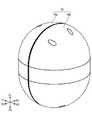
本実施の形態における力覚生成装置について、図1から図3に基づき説明する。図1は、本実施の形態における力覚生成装置の外観の斜視図であり、図2は、内部構造を示す斜視図であり、図3は、分解斜視図である。 The force sensation generator according to the present embodiment will be described with reference to FIGS. 1 to 3. FIG. 1 is a perspective view of the appearance of the force sensation generator according to the present embodiment, FIG. 2 is a perspective view showing an internal structure, and FIG. 3 is an exploded perspective view.
本実施の形態における力覚生成装置は、外側が長球状の筐体10に覆われている。筐体は、Y1側の一方の筐体部10aと、Y2側の他方の筐体部10bとを接続することにより形成されている。図2は、他方の筐体部10bを取り外した状態の斜視図である。筐体10の内部には、第1の回転錘21、22、第2の回転錘31、32、回動ホルダ40等を有している。 The force sensation generator in the present embodiment is covered with a long
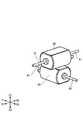
回動ホルダ40は、Z1側に設けられたベアリング41とZ2側に設けられたベアリング42とによりZ1−Z2方向を回転軸として回動可能な状態で、筐体10の内部に取り付けられている。回動ホルダ40は、略立方体の形状で形成されており、図4に示されるように内部に、第1のモータ50及び第2のモータ60を有している。図4は、本実施の形態における力覚生成装置の分解斜視図において、回動ホルダ40の筐体部及びベアリング41、42を取り除いた状態を示す。本願においては、第1のモータ50を第1の回転駆動部と記載し、第2のモータ60を第2の回転駆動部と記載する場合がある。 The
図5は、回動ホルダ40の斜視図であり、図6は、回動ホルダ40の内部の斜視図である。回動ホルダ40の筐体の内部では、第1のモータ50と第2のモータ60は、Z1−Z2方向において重ねて配置されており、第1のモータ50がZ1側、第2のモータ60がZ2側となっている。第1のモータ50には、X1−X2方向に平行な回転軸51が設けられており、回転軸51を中心に回転可能である。また、第2のモータ60には、Y1−Y2方向に平行な回転軸61が設けられており、回転軸61を中心に回転可能である。 FIG. 5 is a perspective view of the rotating
図5に示されるように、回動ホルダ40の筐体のX1側のYZ面に平行な面には、貫通孔43が設けられており、第1のモータ50の回転軸51のX1側の部分が、貫通孔43より回動ホルダ40の筐体の外側に出ている。また、回動ホルダ40の筐体のY2側のZX面に平行な面には、貫通孔44が設けられており、第2のモータ60の回転軸61のY2側の部分が、貫通孔44より回動ホルダ40の筐体の外側に出ている。同様に、図示はしないが、回動ホルダ40の筐体のX2側のYZ面に平行な面には、貫通孔が設けられており、第1のモータ50の回転軸51のX2側の部分が、貫通孔より回動ホルダ40の筐体の外側に出ている。また、回動ホルダ40の筐体のY1側のZX面に平行な面には、貫通孔が設けられており、第2のモータ60の回転軸61のY1側の部分が、貫通孔より回動ホルダ40の筐体の外側に出ている。 As shown in FIG. 5, a
図7は、回動ホルダ40に、第1の回転錘21、22、第2の回転錘31、32が取り付けられている状態の斜視図であり、図8は、第1のモータ50及び第2のモータ60と、第1の回転錘21、22、第2の回転錘31、32との関係を示す斜視図である。図7及び図8に示されるように、第1のモータ50の回転軸51のX1側の端部には第1の回転錘21が取り付けられており、第1のモータ50の回転軸51のX2側の端部には第1の回転錘22が取り付けられている。第1のモータ50の回転軸51を回転させることにより、回転軸51のX1−X2方向の両端に取り付けられている第1の回転錘21及び第1の回転錘22を回転させることができる。 FIG. 7 is a perspective view of a state in which the first
また、第2のモータ60の回転軸61のY1側の端部には第2の回転錘31が取り付けられており、第2のモータ60の回転軸61のY2側の端部には第2の回転錘32が取り付けられている。第2のモータ60の回転軸61を回転させることにより、回転軸61のY1−Y2方向の両端に取り付けられている第2の回転錘31及び第2の回転錘32を回転させることができる。 Further, a second
本実施の形態においては、第1のモータ50の回転軸51を回転させることにより、回転軸51のX1−X2方向の両端に取り付けられている第1の回転錘21及び第1の回転錘22が回転し、ジャイロ効果により、回転軸51の方向を保ち、この状態を維持しようとする。同様に、第2のモータ60の回転軸61を回転させることにより、回転軸61のY1−Y2方向の両端に取り付けられている第2の回転錘31及び第2の回転錘32が回転し、ジャイロ効果により、回転軸61の方向を保ち、この状態を維持しようとする。 In the present embodiment, the first
本実施の形態における力覚生成装置は、人の手により筐体10を握った状態等で使用する。このような状態で、本実施の形態における力覚生成装置を傾けた場合、ジャイロ効果により、回転軸51の方向を保ち、この状態を維持しようとし、また、回転軸61の方向を保ち、この状態を維持しようとする。このため、本実施の形態における力覚生成装置を持った手に抵抗感を感じる。 The force sensation generator in the present embodiment is used in a state where the
更に、本実施の形態における力覚生成装置を傾けることにより、ジャイロ効果の反作用により揺動が生じ、この揺動による振動が、筐体を介し人に伝わり、人が力覚として振動も得ることができる。具体的には、筐体10の内部において、回動ホルダ40はZ1−Z2軸を中心に回動可能な状態で取り付けられている。本実施の形態における力覚生成装置を傾けることにより、ジャイロ効果の反作用により揺動が生じると、この揺動により、回動ホルダ40がZ1−Z2軸を中心に時計回り反時計回りに交互に回動し、この回動により振動が生じる。この振動が筐体10を握っている人の手に伝わり、人は振動を感じることができる。 Further, by tilting the force sensation generator in the present embodiment, vibration occurs due to the reaction of the gyro effect, and the vibration caused by this vibration is transmitted to a person through the housing, and the person also obtains vibration as a force sensation. Can be done. Specifically, inside the
よって、本実施の形態における力覚生成装置では、力覚生成装置を傾けることにより、抵抗感と振動との双方の力覚を得ることができる。 Therefore, in the force sense generation device of the present embodiment, by tilting the force sense generation device, it is possible to obtain both a sense of resistance and a force sense of vibration.
〔第2の実施の形態〕
次に、第2の実施の形態における力覚生成装置について説明する。第1の実施の形態における力覚生成装置は、2軸の回転軸で第1の回転錘と第2の回転錘を回転させていたが、本実施の形態における力覚生成装置では、1軸の回転軸で回転錘を回転させるものである。このような構成の力覚生成装置においても、力覚生成装置を傾けると、抵抗感と振動との双方の力覚を感じることができる。[Second Embodiment]
Next, the force sense generator according to the second embodiment will be described. In the force sense generation device of the first embodiment, the first rotary weight and the second rotary weight are rotated by the two axes of rotation, but in the force sense generation device of the present embodiment, one axis. The rotary weight is rotated by the rotation axis of. Even in a force sense generator having such a configuration, when the force sense generator is tilted, both a sense of resistance and a sense of vibration can be felt.
具体的には、本実施の形態における力覚生成装置は、図9及び図10に示されるように、筐体110の内部に、第1の回転錘21、22、回動ホルダ40等を有している。回動ホルダ40の内部には、X1−X2方向を軸に回転する回転軸51を有する第1のモータ50は設けられてはいるが、第2のモータ60は設けられてはいない。本実施の形態においては、回動ホルダ40はZ1−Z2方向の回動軸141を中心に回動可能な状態で筐体110の内部に取り付けられている。 Specifically, as shown in FIGS. 9 and 10, the force sensation generator according to the present embodiment has the first
第1のモータ50の回転軸51のX1側の端部には第1の回転錘21が取り付けられており、X2側の端部には第1の回転錘22が取り付けられており、第1のモータ50が回転軸51を中心に回転することにより、回転軸51の両端に取り付けられている第1の回転錘21、22が回転する。 The first
図11に示されるように、本実施の形態における力覚生成装置をX2方向に傾けると、X1−X2方向の回転軸51を中心に回転している第1の回転錘21、22のジャイロ効果により、回転軸51の方向を保ち、この状態を維持しようとし、この状態を維持しようとする。このため、抵抗感を感じることができる。 As shown in FIG. 11, when the force sense generator in the present embodiment is tilted in the X2 direction, the gyro effect of the first
また、本実施の形態における力覚生成装置を傾けることにより、ジャイロ効果の反作用により揺動が生じると、この揺動により、回動ホルダ40がZ1−Z2方向の回動軸141を中心に時計回り反時計回りに交互に回動し、この回動により振動が生じる。この振動が筐体110を握っている人の手に伝わり、人は振動を感じることができる。 Further, when the force sense generator in the present embodiment is tilted to cause a swing due to the reaction of the gyro effect, the swing causes the
尚、上記以外の内容については、第1の実施の形態と同様である。 The contents other than the above are the same as those in the first embodiment.
以上、実施の形態について詳述したが、特定の実施形態に限定されるものではなく、特許請求の範囲に記載された範囲内において、種々の変形及び変更が可能である。 Although the embodiments have been described in detail above, the embodiments are not limited to the specific embodiments, and various modifications and changes can be made within the scope of the claims.
10 筐体
10a 一方の筐体部
10b 他方の筐体部
21、22 第1の回転錘
31、32 第2の回転錘
40 回動ホルダ
41、42 ベアリング
43、44 貫通孔
50 第1のモータ
60 第2のモータ10
Claims (4)
Translated fromJapanese前記筐体の内部において、第1の方向を軸に回動可能な状態で取り付けられている回動ホルダと、
前記回動ホルダの内部に設けられた前記第1の方向と直交する第2の方向を回転軸として回転する第1の回転駆動部と、
前記第1の回転駆動部の回転軸に取り付けられた第1の回転錘と、
を有し、
前記筐体を傾ける操作をすることにより力覚が生成されることを特徴とする力覚生成装置。With the housing
A rotating holder mounted inside the housing so as to be rotatable about the first direction,
A first rotation drive unit provided inside the rotation holder and rotating about a second direction orthogonal to the first direction as a rotation axis.
A first rotary weight attached to the rotary shaft of the first rotary drive unit, and
Have,
A force sense generating device characterized in that a force sense is generated by an operation of tilting the housing.
前記第2の回転駆動部の回転軸に取り付けられた第2の回転錘と、
を有することを特徴とする請求項1に記載の力覚生成装置。A second rotation drive unit provided inside the rotation holder and rotating about the first direction and a third direction orthogonal to the second direction as a rotation axis.
A second rotary weight attached to the rotary shaft of the second rotary drive unit, and
The force sense generating device according to claim 1, wherein the force sense generating device is characterized by having.
前記第1の回転錘は、前記回動ホルダの外側に2つ設けられており、第1の回転駆動部の回転軸の両端に取り付けられており、
前記第2の回転錘は、前記回動ホルダの外側に2つ設けられており、第2の回転駆動部の回転軸の両端に取り付けられていることを特徴とする請求項2に記載の力覚生成装置。Inside the housing
Two of the first rotary weights are provided on the outside of the rotary holder, and are attached to both ends of the rotary shaft of the first rotary drive unit.
The force according to claim 2, wherein two of the second rotary weights are provided on the outside of the rotary holder and are attached to both ends of the rotary shaft of the second rotary drive unit. Sense generator.
Priority Applications (1)
| Application Number | Priority Date | Filing Date | Title |
|---|---|---|---|
| JP2019185749AJP7344742B2 (en) | 2019-10-09 | 2019-10-09 | Force sensation generation device |
Applications Claiming Priority (1)
| Application Number | Priority Date | Filing Date | Title |
|---|---|---|---|
| JP2019185749AJP7344742B2 (en) | 2019-10-09 | 2019-10-09 | Force sensation generation device |
Publications (2)
| Publication Number | Publication Date |
|---|---|
| JP2021060896Atrue JP2021060896A (en) | 2021-04-15 |
| JP7344742B2 JP7344742B2 (en) | 2023-09-14 |
Family
ID=75380282
Family Applications (1)
| Application Number | Title | Priority Date | Filing Date |
|---|---|---|---|
| JP2019185749AActiveJP7344742B2 (en) | 2019-10-09 | 2019-10-09 | Force sensation generation device |
Country Status (1)
| Country | Link |
|---|---|
| JP (1) | JP7344742B2 (en) |
Citations (4)
| Publication number | Priority date | Publication date | Assignee | Title |
|---|---|---|---|---|
| JPH0461598U (en)* | 1990-10-05 | 1992-05-27 | ||
| JP2005190465A (en)* | 2003-11-20 | 2005-07-14 | National Institute Of Advanced Industrial & Technology | Tactile sensation information presentation system and method |
| JP2009075861A (en)* | 2007-09-20 | 2009-04-09 | Panasonic Corp | Input device and input system |
| JP2009289015A (en)* | 2008-05-29 | 2009-12-10 | Sharp Corp | Force-applying input apparatus |
- 2019
- 2019-10-09JPJP2019185749Apatent/JP7344742B2/enactiveActive
Patent Citations (4)
| Publication number | Priority date | Publication date | Assignee | Title |
|---|---|---|---|---|
| JPH0461598U (en)* | 1990-10-05 | 1992-05-27 | ||
| JP2005190465A (en)* | 2003-11-20 | 2005-07-14 | National Institute Of Advanced Industrial & Technology | Tactile sensation information presentation system and method |
| JP2009075861A (en)* | 2007-09-20 | 2009-04-09 | Panasonic Corp | Input device and input system |
| JP2009289015A (en)* | 2008-05-29 | 2009-12-10 | Sharp Corp | Force-applying input apparatus |
Also Published As
| Publication number | Publication date |
|---|---|
| JP7344742B2 (en) | 2023-09-14 |
Similar Documents
| Publication | Publication Date | Title |
|---|---|---|
| KR101296925B1 (en) | Tactile force sense communication system | |
| US10226792B2 (en) | Synchronized array of vibration actuators in an integrated module | |
| JP5417663B2 (en) | Tactile feedback using rotary harmonic motion mass | |
| US20180169702A1 (en) | Differential haptic guidance for personal navigation | |
| TW201005469A (en) | Device with spatially unrestricted force feedback | |
| US11707765B2 (en) | Game controller with vibration accuators | |
| US10310602B2 (en) | Controlled gyroscopic torque for an electronic device | |
| JP7344742B2 (en) | Force sensation generation device | |
| TW200909033A (en) | A force-feedback apparatus and system using thereof | |
| JP2010176290A (en) | Inner force sense presentation device, and display device and portable device having the same | |
| JP7704223B2 (en) | force sense presentation device | |
| JP7081819B2 (en) | Force sensation generator | |
| JP2020204951A (en) | Force sense generating apparatus | |
| JP2011244982A (en) | Physical training device | |
| JP2025089983A (en) | operating device | |
| WO2025121267A1 (en) | Operation device | |
| WO2024090137A1 (en) | Operating device | |
| JP2020004337A (en) | Force sense presentation device | |
| JP2011224116A (en) | Rocking device | |
| JP2003053264A (en) | Centrifugal force generation/control/perception apparatus |
Legal Events
| Date | Code | Title | Description |
|---|---|---|---|
| A621 | Written request for application examination | Free format text:JAPANESE INTERMEDIATE CODE: A621 Effective date:20220927 | |
| A977 | Report on retrieval | Free format text:JAPANESE INTERMEDIATE CODE: A971007 Effective date:20230530 | |
| A131 | Notification of reasons for refusal | Free format text:JAPANESE INTERMEDIATE CODE: A131 Effective date:20230620 | |
| A521 | Request for written amendment filed | Free format text:JAPANESE INTERMEDIATE CODE: A523 Effective date:20230814 | |
| TRDD | Decision of grant or rejection written | ||
| A01 | Written decision to grant a patent or to grant a registration (utility model) | Free format text:JAPANESE INTERMEDIATE CODE: A01 Effective date:20230829 | |
| A61 | First payment of annual fees (during grant procedure) | Free format text:JAPANESE INTERMEDIATE CODE: A61 Effective date:20230904 | |
| R150 | Certificate of patent or registration of utility model | Ref document number:7344742 Country of ref document:JP Free format text:JAPANESE INTERMEDIATE CODE: R150 |