JP2021058061A - Information processing device, system, method, and program - Google Patents
Information processing device, system, method, and programDownload PDFInfo
- Publication number
- JP2021058061A JP2021058061AJP2019181854AJP2019181854AJP2021058061AJP 2021058061 AJP2021058061 AJP 2021058061AJP 2019181854 AJP2019181854 AJP 2019181854AJP 2019181854 AJP2019181854 AJP 2019181854AJP 2021058061 AJP2021058061 AJP 2021058061A
- Authority
- JP
- Japan
- Prior art keywords
- identification information
- supply target
- information
- energy
- terminal device
- Prior art date
- Legal status (The legal status is an assumption and is not a legal conclusion. Google has not performed a legal analysis and makes no representation as to the accuracy of the status listed.)
- Granted
Links
Images


Classifications
- G—PHYSICS
- G05—CONTROLLING; REGULATING
- G05B—CONTROL OR REGULATING SYSTEMS IN GENERAL; FUNCTIONAL ELEMENTS OF SUCH SYSTEMS; MONITORING OR TESTING ARRANGEMENTS FOR SUCH SYSTEMS OR ELEMENTS
- G05B19/00—Programme-control systems
- G05B19/02—Programme-control systems electric
- G05B19/04—Programme control other than numerical control, i.e. in sequence controllers or logic controllers
- G05B19/042—Programme control other than numerical control, i.e. in sequence controllers or logic controllers using digital processors
- G—PHYSICS
- G06—COMPUTING OR CALCULATING; COUNTING
- G06K—GRAPHICAL DATA READING; PRESENTATION OF DATA; RECORD CARRIERS; HANDLING RECORD CARRIERS
- G06K7/00—Methods or arrangements for sensing record carriers, e.g. for reading patterns
- G06K7/10—Methods or arrangements for sensing record carriers, e.g. for reading patterns by electromagnetic radiation, e.g. optical sensing; by corpuscular radiation
- G06K7/14—Methods or arrangements for sensing record carriers, e.g. for reading patterns by electromagnetic radiation, e.g. optical sensing; by corpuscular radiation using light without selection of wavelength, e.g. sensing reflected white light
- G06K7/1404—Methods for optical code recognition
- G06K7/1408—Methods for optical code recognition the method being specifically adapted for the type of code
- G06K7/1417—2D bar codes
- H—ELECTRICITY
- H04—ELECTRIC COMMUNICATION TECHNIQUE
- H04L—TRANSMISSION OF DIGITAL INFORMATION, e.g. TELEGRAPHIC COMMUNICATION
- H04L63/00—Network architectures or network communication protocols for network security
- H04L63/08—Network architectures or network communication protocols for network security for authentication of entities
- H04L63/083—Network architectures or network communication protocols for network security for authentication of entities using passwords
- H—ELECTRICITY
- H04—ELECTRIC COMMUNICATION TECHNIQUE
- H04L—TRANSMISSION OF DIGITAL INFORMATION, e.g. TELEGRAPHIC COMMUNICATION
- H04L63/00—Network architectures or network communication protocols for network security
- H04L63/08—Network architectures or network communication protocols for network security for authentication of entities
- H04L63/0876—Network architectures or network communication protocols for network security for authentication of entities based on the identity of the terminal or configuration, e.g. MAC address, hardware or software configuration or device fingerprint
- H—ELECTRICITY
- H04—ELECTRIC COMMUNICATION TECHNIQUE
- H04W—WIRELESS COMMUNICATION NETWORKS
- H04W12/00—Security arrangements; Authentication; Protecting privacy or anonymity
- H04W12/06—Authentication
- H—ELECTRICITY
- H04—ELECTRIC COMMUNICATION TECHNIQUE
- H04W—WIRELESS COMMUNICATION NETWORKS
- H04W12/00—Security arrangements; Authentication; Protecting privacy or anonymity
- H04W12/60—Context-dependent security
- H04W12/69—Identity-dependent
- H04W12/71—Hardware identity
- H—ELECTRICITY
- H04—ELECTRIC COMMUNICATION TECHNIQUE
- H04W—WIRELESS COMMUNICATION NETWORKS
- H04W12/00—Security arrangements; Authentication; Protecting privacy or anonymity
- H04W12/60—Context-dependent security
- H04W12/69—Identity-dependent
- H04W12/72—Subscriber identity
- H—ELECTRICITY
- H04—ELECTRIC COMMUNICATION TECHNIQUE
- H04W—WIRELESS COMMUNICATION NETWORKS
- H04W4/00—Services specially adapted for wireless communication networks; Facilities therefor
- H04W4/30—Services specially adapted for particular environments, situations or purposes
- H04W4/40—Services specially adapted for particular environments, situations or purposes for vehicles, e.g. vehicle-to-pedestrians [V2P]
- H—ELECTRICITY
- H04—ELECTRIC COMMUNICATION TECHNIQUE
- H04W—WIRELESS COMMUNICATION NETWORKS
- H04W4/00—Services specially adapted for wireless communication networks; Facilities therefor
- H04W4/80—Services using short range communication, e.g. near-field communication [NFC], radio-frequency identification [RFID] or low energy communication
- G—PHYSICS
- G05—CONTROLLING; REGULATING
- G05B—CONTROL OR REGULATING SYSTEMS IN GENERAL; FUNCTIONAL ELEMENTS OF SUCH SYSTEMS; MONITORING OR TESTING ARRANGEMENTS FOR SUCH SYSTEMS OR ELEMENTS
- G05B2219/00—Program-control systems
- G05B2219/20—Pc systems
- G05B2219/26—Pc applications
- G05B2219/2637—Vehicle, car, auto, wheelchair
- G—PHYSICS
- G05—CONTROLLING; REGULATING
- G05B—CONTROL OR REGULATING SYSTEMS IN GENERAL; FUNCTIONAL ELEMENTS OF SUCH SYSTEMS; MONITORING OR TESTING ARRANGEMENTS FOR SUCH SYSTEMS OR ELEMENTS
- G05B2219/00—Program-control systems
- G05B2219/20—Pc systems
- G05B2219/26—Pc applications
- G05B2219/2639—Energy management, use maximum of cheap power, keep peak load low
Landscapes
- Engineering & Computer Science (AREA)
- Computer Security & Cryptography (AREA)
- Computer Networks & Wireless Communication (AREA)
- Signal Processing (AREA)
- Physics & Mathematics (AREA)
- General Physics & Mathematics (AREA)
- Automation & Control Theory (AREA)
- Computer Hardware Design (AREA)
- General Engineering & Computer Science (AREA)
- Computing Systems (AREA)
- Toxicology (AREA)
- Health & Medical Sciences (AREA)
- Electromagnetism (AREA)
- General Health & Medical Sciences (AREA)
- Artificial Intelligence (AREA)
- Computer Vision & Pattern Recognition (AREA)
- Theoretical Computer Science (AREA)
- Power Engineering (AREA)
- Charge And Discharge Circuits For Batteries Or The Like (AREA)
- Remote Monitoring And Control Of Power-Distribution Networks (AREA)
- Management, Administration, Business Operations System, And Electronic Commerce (AREA)
Abstract
Description
Translated fromJapanese本発明は、電力などのエネルギーの利用を管理する情報処理装置、システム、方法及びプログラムに関するものである。 The present invention relates to information processing devices, systems, methods and programs that manage the use of energy such as electric power.
従来、コンセントやプラグ等の電力入出力部を介した電力利用を管理するシステムが知られている。例えば、特許文献1には、電力線から電力の供給を受け、キーコードに基づいて電力の供給を制御する電力供給ゲート装置と、前記電力供給ゲート装置を識別するための識別情報に対応したキーコードを送信するサーバ装置と、モバイルコンセントとを備えたシステムが開示されている。モバイルコンセントは、電力供給ゲート装置に着脱可能であり、電力供給ゲート装置から識別情報を受け、その識別情報に対応したキーコードをサーバ装置より受け、前記キーコードを電力供給ゲート装置に与える。この特許文献1のシステムによれば、外出先などであっても、モバイルコンセントを電力供給ゲート装置に装着することにより、簡単に電力の使用が可能となるとされている。 Conventionally, a system for managing power usage via a power input / output unit such as an outlet or a plug has been known. For example, Patent Document 1 describes a power supply gate device that receives power from a power line and controls the power supply based on a key code, and a key code corresponding to identification information for identifying the power supply gate device. A system including a server device for transmitting power and a mobile outlet is disclosed. The mobile outlet is removable from the power supply gate device, receives identification information from the power supply gate device, receives a key code corresponding to the identification information from the server device, and gives the key code to the power supply gate device. According to the system of Patent Document 1, it is said that electric power can be easily used by attaching a mobile outlet to a power supply gate device even when going out.
しかしながら、上記従来のシステムでは、電力線からの電力の供給を制御する電力供給ゲート装置を追加装置として設ける必要があり、また、電力供給ゲート装置及びサーバと間で認証情報(識別情報、キーコード)の送受信を行う専用の認証機能を有するモバイルコンセントが必要である、という課題がある。 However, in the above-mentioned conventional system, it is necessary to provide a power supply gate device for controlling the supply of power from the power line as an additional device, and authentication information (identification information, key code) between the power supply gate device and the server. There is a problem that a mobile outlet having a dedicated authentication function for transmitting and receiving is required.
本発明の一態様に係る情報処理装置は、エネルギーの利用を管理する情報処理装置である。この情報処理装置は、利用者の端末装置から、エネルギー出力部に付されているコード画像の読取データと、前記利用者又は前記端末装置の識別情報と、前記エネルギー出力部からエネルギーが供給される供給対象の識別情報とを受信する端末通信部と、前記利用者又は前記端末装置の識別情報と前記供給対象の識別情報とに基づいて認証を行う認証処理部と、前記供給対象から、前記供給対象の識別情報と、前記エネルギー出力部から供給されて前記供給対象で利用されたエネルギー利用情報とを受信する供給対象通信部と、前記コード画像の読取データに基づいて前記エネルギー出力部の識別情報を特定し、前記エネルギー出力部の識別情報と前記利用者又は前記端末装置の識別情報と前記供給対象の識別情報と前記エネルギー利用情報とを互いに対応付けて記憶する記憶部と、を備える。 The information processing device according to one aspect of the present invention is an information processing device that manages the use of energy. In this information processing device, the read data of the code image attached to the energy output unit, the identification information of the user or the terminal device, and the energy are supplied from the energy output unit from the user's terminal device. A terminal communication unit that receives the identification information of the supply target, an authentication processing unit that authenticates based on the identification information of the user or the terminal device and the identification information of the supply target, and the supply from the supply target. Identification information of the energy output unit based on the supply target communication unit that receives the target identification information and the energy utilization information supplied from the energy output unit and used by the supply target, and the read data of the code image. Is provided, and a storage unit that stores the identification information of the energy output unit, the identification information of the user or the terminal device, the identification information of the supply target, and the energy utilization information in association with each other is provided.
本発明の他の態様に係る情報処理装置は、エネルギーの利用を管理する情報処理装置である。この情報処理装置は、利用者の端末装置から、エネルギー出力部に付されている識別補助画像の読取データと、前記端末装置の位置情報と、前記利用者又は前記端末装置の識別情報と、前記エネルギー出力部からエネルギーが供給される供給対象の識別情報とを受信する端末通信部と、前記利用者又は前記端末装置の識別情報と前記供給対象の識別情報とに基づいて認証を行う認証処理部と、前記供給対象から、前記供給対象の識別情報と、前記エネルギー出力部から供給されて前記供給対象で利用されたエネルギー利用情報とを受信する供給対象通信部と、前記識別補助画像の読取データと前記位置情報とに基づいて前記エネルギー出力部の識別情報を特定し、前記エネルギー出力部の識別情報と前記利用者又は前記端末装置の識別情報と前記供給対象の識別情報と前記エネルギー利用情報とを互いに対応付けて記憶する記憶部と、を備える。 The information processing device according to another aspect of the present invention is an information processing device that manages the use of energy. This information processing device includes reading data of an identification auxiliary image attached to an energy output unit from a user's terminal device, position information of the terminal device, identification information of the user or the terminal device, and the above. A terminal communication unit that receives the identification information of the supply target to which energy is supplied from the energy output unit, and an authentication processing unit that performs authentication based on the identification information of the user or the terminal device and the identification information of the supply target. The supply target communication unit that receives the identification information of the supply target and the energy utilization information supplied from the energy output unit and used by the supply target from the supply target, and the reading data of the identification auxiliary image. The identification information of the energy output unit is specified based on the position information, the identification information of the energy output unit, the identification information of the user or the terminal device, the identification information of the supply target, and the energy utilization information. A storage unit for storing the data in association with each other is provided.
本発明の更に他の態様に係る方法は、エネルギーの利用を管理する方法である。この方法は、利用者の端末装置から、エネルギー出力部に付されているコード画像の読取データと、前記利用者又は前記端末装置の識別情報と、前記エネルギー出力部からエネルギーが供給される供給対象の識別情報とを受信することと、前記利用者又は前記端末装置の識別情報と前記供給対象の識別情報とに基づいて認証を行うことと、前記供給対象から、前記供給対象の識別情報と、前記エネルギー出力部から供給されて前記供給対象で利用されたエネルギー利用情報とを受信することと、前記コード画像の読取データに基づいて前記エネルギー出力部の識別情報を特定し、前記エネルギー出力部の識別情報と前記利用者又は前記端末装置の識別情報と前記供給対象の識別情報と前記エネルギー利用情報とを互いに対応付けて記憶することと、を含む。 A method according to yet another aspect of the present invention is a method of controlling the use of energy. In this method, the reading data of the code image attached to the energy output unit from the user's terminal device, the identification information of the user or the terminal device, and the supply target to which energy is supplied from the energy output unit. Authentication is performed based on the identification information of the user or the terminal device and the identification information of the supply target, and the identification information of the supply target from the supply target and the identification information of the supply target. Receiving the energy utilization information supplied from the energy output unit and used in the supply target, and specifying the identification information of the energy output unit based on the read data of the code image, the energy output unit of the energy output unit It includes storing the identification information, the identification information of the user or the terminal device, the identification information of the supply target, and the energy utilization information in association with each other.
本発明の更に他の態様に係る方法は、エネルギーの利用を管理する方法である。この方法は、利用者の端末装置から、エネルギー出力部に付されている識別補助画像の読取データと、前記端末装置の位置情報と、前記利用者又は前記端末装置の識別情報と、前記エネルギー出力部からエネルギーが供給される供給対象の識別情報とを受信することと、前記利用者又は前記端末装置の識別情報と前記供給対象の識別情報とに基づいて認証を行うことと、前記供給対象から、前記供給対象の識別情報と、前記エネルギー出力部から供給されて前記供給対象で利用されたエネルギー利用情報とを受信することと、前記識別補助画像の読取データと前記位置情報とに基づいて前記エネルギー出力部の識別情報を特定し、前記エネルギー出力部の識別情報と前記利用者又は前記端末装置の識別情報と前記供給対象の識別情報と前記エネルギー利用情報とを互いに対応付けて記憶することと、を含む。 A method according to yet another aspect of the present invention is a method of controlling the use of energy. In this method, the reading data of the identification auxiliary image attached to the energy output unit, the position information of the terminal device, the identification information of the user or the terminal device, and the energy output from the user's terminal device are used. Receiving the identification information of the supply target to which energy is supplied from the unit, performing authentication based on the identification information of the user or the terminal device and the identification information of the supply target, and from the supply target Based on the reception of the identification information of the supply target and the energy utilization information supplied from the energy output unit and used by the supply target, and the reading data of the identification auxiliary image and the position information. Identifying the identification information of the energy output unit, and storing the identification information of the energy output unit, the identification information of the user or the terminal device, the identification information of the supply target, and the energy utilization information in association with each other. ,including.
本発明の更に他の態様に係るプログラムは、エネルギーの利用を管理する情報処理装置に備えるコンピュータ又はプロセッサにおいて実行されるプログラムである。このプログラムは、利用者の端末装置から、エネルギー出力部に付されているコード画像の読取データと、前記利用者又は前記端末装置の識別情報と、前記エネルギー出力部からエネルギーが供給される供給対象の識別情報とを受信するためのプログラムコードと、前記利用者又は前記端末装置の識別情報と前記供給対象の識別情報とに基づいて認証を行うためのプログラムコードと、前記供給対象から、前記供給対象の識別情報と、前記エネルギー出力部から供給されて前記供給対象で利用されたエネルギー利用情報とを受信するためのプログラムコードと、前記コード画像の読取データに基づいて前記エネルギー出力部の識別情報を特定し、前記エネルギー出力部の識別情報と前記利用者又は前記端末装置の識別情報と前記供給対象の識別情報と前記エネルギー利用情報とを互いに対応付けて記憶するためのプログラムコードと、を含む。 A program according to still another aspect of the present invention is a program executed by a computer or processor provided in an information processing device that manages the use of energy. This program includes reading data of a code image attached to an energy output unit from a user's terminal device, identification information of the user or the terminal device, and a supply target to which energy is supplied from the energy output unit. A program code for receiving the identification information of the above, a program code for performing authentication based on the identification information of the user or the terminal device and the identification information of the supply target, and the supply from the supply target. Identification information of the energy output unit based on the program code for receiving the identification information of the target, the energy utilization information supplied from the energy output unit and used by the supply target, and the read data of the code image. Is included, and includes a program code for storing the identification information of the energy output unit, the identification information of the user or the terminal device, the identification information of the supply target, and the energy utilization information in association with each other. ..
本発明の更に他の態様に係るプログラムは、エネルギーの利用を管理する情報処理装置に備えるコンピュータ又はプロセッサにおいて実行されるプログラムである。このプログラムは、利用者の端末装置から、エネルギー出力部に付されている識別補助画像の読取データと、前記端末装置の位置情報と、前記利用者又は前記端末装置の識別情報と、前記エネルギー出力部からエネルギーが供給される供給対象の識別情報とを受信するためのプログラムコードと、前記利用者又は前記端末装置の識別情報と前記供給対象の識別情報とに基づいて認証を行うためのプログラムコードと、前記供給対象から、前記供給対象の識別情報と、前記エネルギー出力部から供給されて前記供給対象で利用されたエネルギー利用情報とを受信するためのプログラムコードと、前記識別補助画像の読取データと前記位置情報とに基づいて前記エネルギー出力部の識別情報を特定し、前記エネルギー出力部の識別情報と前記利用者又は前記端末装置の識別情報と前記供給対象の識別情報と前記エネルギー利用情報とを互いに対応付けて記憶するためのプログラムコードと、を含む。 A program according to still another aspect of the present invention is a program executed by a computer or processor provided in an information processing device that manages the use of energy. In this program, the reading data of the identification auxiliary image attached to the energy output unit, the position information of the terminal device, the identification information of the user or the terminal device, and the energy output from the user's terminal device. A program code for receiving the identification information of the supply target to which energy is supplied from the unit, and a program code for performing authentication based on the identification information of the user or the terminal device and the identification information of the supply target. The program code for receiving the identification information of the supply target from the supply target, the energy utilization information supplied from the energy output unit and used by the supply target, and the reading data of the identification auxiliary image. The identification information of the energy output unit is specified based on the position information, the identification information of the energy output unit, the identification information of the user or the terminal device, the identification information of the supply target, and the energy utilization information. Includes a program code for storing the data in association with each other.
本発明の更に他の態様に係るエネルギーの利用を管理するシステムは、前記いずれかの情報処理装置と、前記端末装置及び前記供給対象の少なくとも一方とを備える。 A system that manages the use of energy according to still another aspect of the present invention includes any of the information processing devices, the terminal device, and at least one of the supply targets.
前記情報処理装置、前記方法及び前記プログラムにおいて、前記識別補助画像は、前記エネルギー出力部に付された着脱可能なシール部材に描かれた文字、図柄、イラスト又はマークであってもよい。
前記情報処理装置、前記方法及び前記プログラムにおいて、前記エネルギー出力部を介した前記供給対象によるエネルギー利用の利用料金について、前記利用者、前記供給対象及び前記端末装置の少なくとも一つに対して課金する処理を行ってもよい。
前記情報処理装置、前記方法及び前記プログラムにおいて、前記供給対象で利用されるエネルギーは電力であり、前記エネルギー出力部はコンセントであり、前記エネルギー利用情報は前記供給対象で利用された電力量を含んでもよい。
前記情報処理装置、前記方法及び前記プログラムにおいて、前記供給対象は車両であり、前記供給対象の識別情報及び前記エネルギー利用情報を、前記車両の車載装置に搭載された外部通信部から受信してもよい。In the information processing device, the method, and the program, the identification auxiliary image may be characters, symbols, illustrations, or marks drawn on a removable seal member attached to the energy output unit.
In the information processing device, the method, and the program, at least one of the user, the supply target, and the terminal device is charged for the usage fee of energy utilization by the supply target via the energy output unit. Processing may be performed.
In the information processing device, the method, and the program, the energy used in the supply target is electric power, the energy output unit is an outlet, and the energy utilization information includes the amount of electric power used in the supply target. It may be.
In the information processing device, the method, and the program, the supply target is a vehicle, and even if the supply target identification information and the energy utilization information are received from an external communication unit mounted on the vehicle-mounted device of the vehicle. Good.
本発明によれば、エネルギー出力部に追加装置を設けることなく、エネルギー出力部から供給されて供給対象で利用されるエネルギーについて認証を伴うエネルギー利用管理を実現することができる。 According to the present invention, it is possible to realize energy utilization management accompanied by certification for the energy supplied from the energy output unit and used in the supply target without providing an additional device in the energy output unit.
以下、図面を参照して本発明の実施の形態を説明する。
本発明の実施形態に係るシステムは、エネルギー出力部から供給されて供給対象で利用されるエネルギーの利用を管理するシステムである。利用対象のエネルギーは、例えば、石油、天然ガス、石炭などの形態の一次エネルギーでもよいし、電気、水素、ガソリン、軽油、重油、都市ガス、アルコールなどの形態の二次エネルギーであってもよい。エネルギーが供給される供給対象は、例えば、バッテリー搭載のモータで駆動される電動の移動体である。移動体は、電動車両や燃料電池車両等の地上の移動体でもよいしドローンなどの空中の移動体、海などの水上を移動する船舶等の移動体であってもよい。移動体は、四輪以上の車両、三輪車(トライスクル)、二輪車(バイク、自転車)、トラック、バス、自家用車、事業用車両などの車両であってもよい。バッテリーは、利用者自身が所有するものであってもよいし、リース会社からリースされたものであってもよいし、利用者とは異なる事業者が所有するものであってもよい。また、供給対象は、携帯型又は設置型の家電機器、オフィス機器、通信端末装置等の電気機器や電子機器であってもよい。Hereinafter, embodiments of the present invention will be described with reference to the drawings.
The system according to the embodiment of the present invention is a system that manages the use of energy supplied from the energy output unit and used in the supply target. The energy to be used may be, for example, primary energy in the form of oil, natural gas, coal, etc., or secondary energy in the form of electricity, hydrogen, gasoline, light oil, heavy oil, city gas, alcohol, etc. .. The energy supply target is, for example, an electric mobile body driven by a battery-mounted motor. The moving body may be a moving body on the ground such as an electric vehicle or a fuel cell vehicle, an aerial moving body such as a drone, or a moving body such as a ship moving on water such as the sea. The moving body may be a vehicle having four or more wheels, a tricycle, a two-wheeled vehicle (motorcycle, bicycle), a truck, a bus, a private vehicle, a business vehicle, or the like. The battery may be owned by the user himself / herself, may be leased from a leasing company, or may be owned by a business operator different from the user. Further, the supply target may be an electric device such as a portable or stationary home appliance, an office device, a communication terminal device, or an electronic device.
なお、以下の実施形態では、一例として、利用対象のエネルギーが電気エネルギーであり、そのエネルギーが出力されるエネルギー出力部が電気エネルギーを出力するコンセントであり、エネルギーが供給される供給対象が車両に組み込まれた駆動用のバッテリーであり、コンセントから出力される電力で車両のバッテリーを充電するときの電力利用を管理する電力利用管理システムの場合について説明する。 In the following embodiment, as an example, the energy to be used is electric energy, the energy output unit from which the energy is output is an outlet that outputs electric energy, and the supply target to which the energy is supplied is the vehicle. The case of a power utilization management system that manages the power usage when charging the vehicle battery with the power output from the outlet, which is a built-in drive battery, will be described.
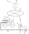
図1は、本実施形態に係る電力利用管理システム10の概略構成の一例を示す説明図である。図1において、電力利用管理システム10は、コンセント20から電力が供給される供給対象の電力利用を管理する。本実施形態の供給対象は、コンセント20からの電力で充電される車両30のバッテリー31である。コンセント20からの電力供給は、例えば、有線の電源ケーブル40及びプラグ41を介して行われる。コンセント20からの電力供給は、電磁誘導、マイクロ波等の電波による給電、レーザー光等の光による給電などの無線給電で行ってもよい。また、コンセント20から供給される電圧(電流)は交流であってもよいし、直流であってもよい。 FIG. 1 is an explanatory diagram showing an example of a schematic configuration of the electric power
電力利用管理システム10は、電力(電気エネルギー)利用を管理する情報処理装置としてのサーバ100を備える。サーバ100は、単体のコンピュータ装置で構成してもよいし、複数のコンピュータ装置を連携させるように構成してもよいし、ネットワーク上のクラウドシステムで構成してもよい。 The electric power
電力(電気エネルギー)を出力可能なエネルギー出力部としてのコンセント20は、例えば、建物の内側又は外側の壁25、屋外又は屋内の充電設備(充電ステーション)のスタンドなどに設けられたコンセントである。コンセント20は、用途が限定されていない汎用のコンセントでもよいし、用途限定の専用のコンセントであってもよい。また、コンセント20は、利用者が限定されていないコンセントでもよいし、特定の利用者のみ利用可能なコンセントであってもよい。 The
図2(a)〜(c)はそれぞれ実施形態に係るコンセント20に付した画像の一例を示す説明図である。図2(a)のコンセント20には、コード画像(例えば、QRコード(登録商標)の画像)21が付されている。コード画像21は、1次元コード画像でもよいし、2次元コード画像であってもよい。コード画像21は、たとえば、コンセント20の名前、識別番号、設置場所、設置主体などの情報が符号化された画像である。 2 (a) to 2 (c) are explanatory views showing an example of an image attached to the
図2(b)のコンセント20には、利用者又は設置主体などが任意に付けたコンセント20の識別補助画像としての文字(例えば手書き文字)22の画像が付されている。また、図2(c)のコンセント20には、利用者又は設置主体などが任意に付けた識別補助画像としてのイラスト23の画像が付されている。文字22又はイラスト23は、コンセント20に付してもよい。コンセント20の文字22及びイラスト23は、利用者又は設置主体などがシール部材24に描いてコンセント20の脇に貼り付けてもよい。なお、識別補助画像は、文字及びイラストのほか、図柄やマークであってもよい。 The
コンセント20から供給される電力を利用しようとする利用者50の端末装置51は、移動通信網、インターネットなどの通信網60を介してサーバ100と通信することができる。端末装置51は、キー、ボタン、タッチパネルなどの操作部、液晶ディスプレイなどの表示部、コンセントのコード画像や識別補助画像などを撮像するカメラなどの撮像部などを備える。端末装置51は、利用者が操作することにより、予め組み込んだ所定の電力利用のアプリケーションを起動して実行することができる。端末装置51は、自装置の現在位置の情報を取得するGNSS受信機などの現在位置取得部を備えてもよい。端末装置51は、例えば、第4世代又は第5世代以降の世代の移動通信網を介して通信可能な移動局(「移動機」、「ユーザ装置(UE)」等ともいう。)であってもよい。 The
車両30は、車載装置の外部通信部32により、通信網60を介してサーバ100と通信することができる。外部通信部32は、例えば、車載ネットワーク(CAN:Controller Area Network)にゲートウェイを介して接続された遠隔制御ユニット(TCU:テレマティック コントロール ユニット)であってもよい。遠隔制御ユニット(TCU)は、通信網60を介した通信機能のほか、無線LANやブルートゥース(登録商標)等の近距離無線通信機能を有してもよい。車載ネットワーク(CAN)には、遠隔制御ユニット(TCU)のほか、バッテリー31を管理するバッテリー管理システム(BMS)や、その他の各部の制御する一又は複数の電子制御ユニット(ECU)が接続されている。 The
バッテリー31の充電に利用された電力に関する電力利用情報(例えば、バッテリー識別情報、電力量、充電開始時間、充電終了時間)は、例えば、バッテリー管理システム(BMS)から遠隔制御ユニット(TCU)を介してサーバ100に送信することができる。また、車両の識別情報は、例えば、車両の基本情報を記憶したメモリを有する電子制御ユニット(ECU)から遠隔制御ユニット(TCU)を介してサーバ100に送信することができる。これらの情報のサーバ100への送信は、例えば、端末装置51で起動しているアプリケーションが生成した送信要求に基づいて実行される。端末装置51からの送信要求は、例えば無線LANやブルートゥース(登録商標)等の近距離無線通信を介して車両の遠隔制御ユニット(TCU)が受信してもよい。 The power usage information (for example, battery identification information, electric energy, charging start time, charging end time) regarding the power used for charging the
図3は、実施形態に係るサーバ100の主要な機能の構成の一例を示すブロック図である。図3において、サーバ100は、端末通信部101と供給対象通信部102と認証処理部103と記憶部(DB:データベース)104とを備える。 FIG. 3 is a block diagram showing an example of the configuration of the main functions of the
電力利用管理の一例において、端末通信部101は、通信網60を介して、利用者50の端末装置51から、コンセント20に付されているコード画像(例えばQRコード(登録商標)の画像)21(図2(a)参照)の読取データと、利用者50又は端末装置51の識別情報と、コンセント20から電力が供給される供給対象の識別情報(例えば、車両30又はバッテリー31の識別情報)とを受信する。コード画像21の読取データは、例えば、コード画像21を端末装置51のカメラで撮像した画像データでもよいし、その画像データを復号化して得られたデータであってもよい。 In an example of power utilization management, the
また、電力利用管理の別の例において、端末通信部101は、通信網60を介して、利用者50の端末装置51から、コンセント20に付されている識別補助画像22又は23(図2(a)及び図2(c)参照)の読取データと、端末装置51の位置情報と、利用者50又は端末装置51の識別情報と、コンセント20から電力が供給される供給対象の識別情報(例えば、車両30又はバッテリー31の識別情報)とを受信する。識別補助画像22、23の読取データは、例えば、識別補助画像22、23を端末装置51のカメラで撮像した画像データである。端末装置51の位置情報は、例えば、端末装置51のGNSS受信機で測位した端末装置51の位置情報(緯度、経度、高度)である。 Further, in another example of power utilization management, the
供給対象通信部102は、供給対象の車両30から、供給対象の識別情報(例えば、車両30又はバッテリー31の識別情報)と、コンセント20から供給されて車両30で利用された電力利用情報(例えば、バッテリー識別情報、電力量、充電開始時間、充電終了時間)とを受信する。 The supply
なお、端末通信部101及び供給対象通信部102は、一体構成の通信装置(例えば移動通信モジュール)で構成してもよい。 The
認証処理部103は、利用者50又は端末装置51の識別情報と供給対象の識別情報(例えば、車両30又はバッテリー31の識別情報)とに基づいて、電力を利用としている利用者の認証(利用者認証)と、供給対象(例えば車両30又はバッテリー31)の認証(供給対象認証)の少なくとも一方を行う。 The
例えば、認証処理部103は、端末装置51から受信した利用者50の識別情報(利用者ID)と、サーバ100に予め登録されている利用者の識別情報(利用者ID)とを比較することにより、利用者50が所定の電力利用管理サービスに予め登録された正規の利用者であるかを確認する利用者認証を行ってもよい。この場合、正規の利用者のときは当該電力利用管理サービスの利用を許可し、正規の利用者でないときは電力利用管理サービスの利用を制限(例えば利用を不許可)にしてもよい。 For example, the
また、例えば、認証処理部103は、端末装置51から受信した供給対象の識別情報(例えば、車両30又はバッテリー31の識別情報)と、車両30から受信した供給対象の識別情報(例えば、車両30又はバッテリー31の識別情報)とを比較することにより、供給対象(例えば、車両30又はバッテリー31)が所定の電力利用管理サービスに予め登録された正規の供給対象であるかを確認する供給対象認証を行ってもよい。この場合、正規の供給対象のときは当該電力利用管理サービスの利用を許可し、正規の供給対象でないときは電力利用管理サービスの利用を制限(例えば利用を不許可)にしてもよい。なお、この認証においては、端末装置51又は車両30から受信した供給対象の識別情報(例えば、車両30又はバッテリー31の識別情報)を、サーバ100に予め登録されている供給対象の識別情報と比較して認証処理を行ってもよい。 Further, for example, the
電力利用管理の一例において、記憶部(DB)104は、コード画像の読取データに基づいてコンセント20の識別情報を特定し、コンセント20の識別情報(コンセントID)と利用者50又は端末装置51の識別情報と供給対象の識別情報(例えば、車両30又はバッテリー31の識別情報)と電力利用情報とを互いに対応付けて記憶する。例えば表1に示すように、一連の電力利用のトランザクションごとに、コンセントIDと利用者IDと端末ID(例えばIMEI)と車両IDと電力利用情報とを互いに対応付けた1レコードが記憶され、全体として、電力利用トランザクションテーブル(電力利用台帳)が形成される。 In an example of power utilization management, the storage unit (DB) 104 identifies the identification information of the

電力利用管理の他の例において、記憶部(DB)104は、前述の識別補助画像の読取データと端末装置51の現在位置情報とに基づいてコンセント20の識別情報を特定し、コンセント20の識別情報(コンセントID)と利用者50又は端末装置51の識別情報と供給対象の識別情報(例えば、車両30又はバッテリー31の識別情報)と電力利用情報とを互いに対応付けて記憶する。 In another example of power utilization management, the storage unit (DB) 104 identifies the identification information of the
また、記憶部(DB)104には、複数のコンセントを介した電力利用管理に用いられる各種テーブルが格納されている。例えば、記憶部(DB)104には、表2のコンセント管理テーブルと、表3のユーザ管理テーブルと、表4の車両管理テーブルを格納されている。 Further, the storage unit (DB) 104 stores various tables used for power utilization management via a plurality of outlets. For example, the storage unit (DB) 104 stores the outlet management table in Table 2, the user management table in Table 3, and the vehicle management table in Table 4.
コンセント管理テーブル、ユーザ管理テーブル及び車両管理テーブルはそれぞれ、本実施形態のサーバ100で提供されるコンセント20を介した電力利用管理サービスを利用するためのコンセント20、利用者50(端末装置51)及び車両30(バッテリー31)の新規登録があったときに新規レコードが追加される。また、表2のコンセント管理テーブルを参照することにより、本実施形態のサーバ100で提供される電力利用管理サービスにおいて利用者が新規に登録することができる公開コンセントの位置を示す公開コンセント仮想空間を構築することできる。この公開コンセント仮想空間を実空間の地図上に重ね合わせて表示することにより、利用者が新規登録可能な公開コンセントの位置を容易に把握してアクセスすることができる。 The outlet management table, the user management table, and the vehicle management table are the
また、記憶部(DB)104には、表5に示す登録コンセントテーブルを格納してもよい。この登録コンセントテーブルには、利用者が新規にコンセント20を登録したときにレコードが追加される。登録コンセントテーブルと前述の各種テーブルとを連結して参照することにより、本実施形態のサーバ100で提供される電力利用管理サービスにおいて利用者が使用できる登録済みのコンセントの位置を示すマイ・コンセント仮想空間を構築することできる。このマイ・コンセント仮想空間を実空間の地図上に重ね合わせて表示することにより、利用者が登録して利用可能なコンセントの位置を容易に把握してアクセスすることができる。
本実施形態において、サーバ100は課金処理部105を備えてもよい。課金処理部105は、コンセント20を介した車両30による電力利用の利用料金について、利用者50、供給対象(車両30又はバッテリー31)及び端末装置51の少なくとも一つに対して課金する処理を行う。例えば、コンセント20を介した車両30による電力利用の利用料金の全額又は一部を、利用者50に課金したり、端末装置51の利用料金に加算するように課金したりしてもよい。車両30やバッテリー31がレンタル会社からレンタルした場合やリース会社からリースされた場合は、コンセント20を介した車両30による電力利用の利用料金の全額又は一部を、レンタル会社やリース会社に課金してもよい。 In this embodiment, the
また、電力利用の課金処理は、課金に関する各種の特典(課金特典)を考慮して行ってもよい。例えば、風力、太陽光、バイオマスなどの再生可能エネルギーが持つ環境価値を証書化した「グリーン電力証書」、「Jクレジット」、「非化石証書」等の環境価値証書又はそれと同等の価値のあるもの(以下、「環境価値証書等の環境価値」という。)が、コンセント20を介して車両30に供給される電流に付加されるとみなされる場合、このような環境価値証書等の環境価値の付加状況を例えば表3のユーザ管理テーブルの課金特典の欄のフラグで管理し、電力量と並行して環境価値に対する課金(増額または減額)を行ってもよい。また、このような環境価値証書等の環境価値の購入等の課金特典の有無は、例えば、表3のユーザ管理テーブルの課金特典の欄のフラグで管理することができる。 In addition, the billing process for using electric power may be performed in consideration of various benefits related to billing (billing benefits). For example, environmental value certificates such as "green power certificate," "J credit," and "non-fossil certificate," which are certificates of the environmental value of renewable energies such as wind power, solar power, and biomass, or those with equivalent value. (Hereinafter, referred to as "environmental value such as an environmental value certificate") is considered to be added to the current supplied to the
図4は、実施形態に係るサーバ100における電力利用管理処理の一例を示すフローチャートである。図4において、本実施形態の電力利用管理処理は、事前準備フェーズ(S100)と運用フェーズ(S200)とを含む。 FIG. 4 is a flowchart showing an example of the power utilization management process in the
事前準備フェーズ(S100)において、サーバ100は、オペレータによって、電力利用管理サービスで公開する複数のコンセント20についてデータ入力が行われ、前述の表2のコンセント管理テーブルを作成する。また、サーバ100は、電力利用管理サービスを利用する複数の利用者50の端末装置51から、利用者50及び端末装置51の情報並びに供給対象(車両30及びバッテリー31)の情報を含む新規登録データを受信することにより、表3のユーザ管理テーブルと表4の車両管理テーブルを作成する。 In the preparatory phase (S100), the
次に、運用フェーズ(S200)において、利用者50は、端末装置51を操作して電力利用管理サービスを利用するためのアプリケーションを起動し、コンセント20の識別情報を含むコード画像21を撮像して読み取るとともに、端末装置51の表示画面に表示されたメニュー選択で「私の車」を選択する。この操作により、利用者50(又は端末装置51)の識別情報と、コード画像21の読取データと、端末装置51に「私の車」として事前登録されている車両30(又はバッテリー31)の識別情報が、サーバ100に送信される。サーバ100は、利用者50の端末装置51から、利用者50(又は端末装置51)の識別情報とコード画像21の読取データと車両30(又はバッテリー31)の識別情報とを受信する(S201)。 Next, in the operation phase (S200), the
次に、サーバ100は、端末装置51から受信した利用者50(又は端末装置51)の識別情報と車両30(又はバッテリー31)の識別情報とに基づいて、利用者50(又は端末装置51)の識別情報と車両30(又はバッテリー31)との組み合わせについて認証処理を行う(S202)。ここで、利用者50についてコンセント20が登録されていない場合、サーバ100は、当該コンセント20を利用者50が利用可能なコンセントとして、前述の表5の登録コンセントテーブルに、互いに対応するコンセントID及び利用者IDを新規登録する(S202)。 Next, the
次に、コンセント20から供給される電力による車両30のバッテリー31の充電が完了すると、車両30は、利用者50の端末装置51からのリクエストにより又は自律的に、供給対象の識別情報(車両30又はバッテリー31の識別情報)と、コンセント20から供給されて車両30のバッテリー31の充電に利用された電力利用情報とを、サーバ100に送信する。サーバ100は、車両30から、供給対象の識別情報(車両30又はバッテリー31の識別情報)と電力利用情報とを受信する(S203)。 Next, when the charging of the
次に、サーバ100は、コード画像の読取データに基づいて前述の表2のコンセント管理テーブルを参照し、コンセント20の識別情報を特定する。更に、サーバ100は、そのコンセント20の識別情報(コンセントID)と利用者50又は端末装置51の識別情報(利用者ID、端末ID)と供給対象の識別情報(車両ID又はバッテリーID)と電力利用情報とを互いに対応付けて、前述の表1の電力利用トランザクションテーブル(電力利用台帳)に追加するように、記憶部(DB)104に記憶する(S204)。 Next, the
サーバ100は、電力利用トランザクションテーブル(電力利用台帳)を参照することにより、電力利用管理サービスにおける各利用者のコンセントを介した電力利用を管理することができる。 The
なお、サーバ100は、電力利用トランザクションテーブル(電力利用台帳)を参照することにより、コンセント20を介した車両30による電力利用の利用料金について、利用者50、供給対象(車両30又はバッテリー31)及び端末装置51の少なくとも一つに対して課金する処理を行ってもよい(S205)。 By referring to the power usage transaction table (power usage ledger), the
また、コンセント20に付されている識別補助画像22又は23(図2(a)及び図2(c)参照)を利用する場合は、図4のステップS201において、サーバ100は、コード画像の読取データの代わりに、識別補助画像22又は23の読取データと端末装置51の位置情報とを、端末装置51から受信する。また、図4のステップS204において、サーバ100は、識別補助画像22又は23の読取データと端末装置51の位置情報とに基づいて、前述の表2のコンセント管理テーブルを参照し、コンセント20の識別情報を特定する。 Further, when the identification
以上、本実施形態によれば、コンセント20に追加装置を設けることなく、コンセント20から供給されて車両30のバッテリー31の充電に利用される電力について認証を伴う電力利用管理を実現することができる。 As described above, according to the present embodiment, it is possible to realize power usage management accompanied by authentication for the power supplied from the
なお、本明細書で説明された処理工程並びに情報処理装置、端末装置、車両の車載装置などの構成要素は、様々な手段によって実装することができる。例えば、これらの工程及び構成要素は、ハードウェア、ファームウェア、ソフトウェア、又は、それらの組み合わせで実装されてもよい。 The processing process described in the present specification and components such as an information processing device, a terminal device, and an in-vehicle device of a vehicle can be implemented by various means. For example, these steps and components may be implemented in hardware, firmware, software, or a combination thereof.
ハードウェア実装については、実体(例えば、コンピュータ装置、サーバ、端末装置(ユーザ装置、移動局、通信端末)、車両の車載装置、ハードディスクドライブ装置、又は、光ディスクドライブ装置)において前記工程及び構成要素を実現するために用いられる処理ユニット等の手段は、1つ又は複数の、特定用途向けIC(ASIC)、デジタルシグナルプロセッサ(DSP)、デジタル信号処理装置(DSPD)、プログラマブル・ロジック・デバイス(PLD)、フィールド・プログラマブル・ゲート・アレイ(FPGA)、プロセッサ、コントローラ、マイクロコントローラ、マイクロプロセッサ、電子デバイス、本明細書で説明された機能を実行するようにデザインされた他の電子ユニット、コンピュータ、又は、それらの組み合わせの中に実装されてもよい。 Regarding hardware implementation, the above steps and components are incorporated in an entity (for example, a computer device, a server, a terminal device (user device, mobile station, communication terminal), an in-vehicle device of a vehicle, a hard disk drive device, or an optical disk drive device). Means such as processing units used to achieve this are one or more application-specific ICs (ASICs), digital signal processors (DSPs), digital signal processing devices (DSPDs), programmable logic devices (PLDs). , Field programmable gate array (FPGA), processor, controller, microcontroller, microprocessor, electronic device, other electronic unit, computer, or electronic device designed to perform the functions described herein. It may be implemented in a combination thereof.
また、ファームウェア及び/又はソフトウェア実装については、前記構成要素を実現するために用いられる処理ユニット等の手段は、本明細書で説明された機能を実行するプログラム(例えば、プロシージャ、関数、モジュール、インストラクション、などのコード)で実装されてもよい。一般に、ファームウェア及び/又はソフトウェアのコードを明確に具体化する任意のコンピュータ/プロセッサ読み取り可能な媒体が、本明細書で説明された前記工程及び構成要素を実現するために用いられる処理ユニット等の手段の実装に利用されてもよい。例えば、ファームウェア及び/又はソフトウェアコードは、例えば制御装置において、メモリに記憶され、コンピュータやプロセッサにより実行されてもよい。そのメモリは、コンピュータやプロセッサの内部に実装されてもよいし、又は、プロセッサの外部に実装されてもよい。また、ファームウェア及び/又はソフトウェアコードは、例えば、ランダムアクセスメモリ(RAM)、リードオンリーメモリ(ROM)、不揮発性ランダムアクセスメモリ(NVRAM)、プログラマブルリードオンリーメモリ(PROM)、電気的消去可能PROM(EEPROM)、FLASHメモリ、フロッピー(登録商標)ディスク、コンパクトディスク(CD)、デジタルバーサタイルディスク(DVD)、磁気又は光データ記憶装置、などのような、コンピュータやプロセッサで読み取り可能な媒体に記憶されてもよい。そのコードは、1又は複数のコンピュータやプロセッサにより実行されてもよく、また、コンピュータやプロセッサに、本明細書で説明された機能性のある態様を実行させてもよい。 For firmware and / or software implementation, means such as processing units used to implement the components are programs (eg, procedures, functions, modules, instructions) that perform the functions described herein. , Etc.) may be implemented. Generally, any computer / processor readable medium that clearly embodies the firmware and / or software code is a means such as a processing unit used to implement the steps and components described herein. May be used to implement. For example, the firmware and / or software code may be stored in memory and executed by a computer or processor, for example, in a control device. The memory may be implemented inside the computer or processor, or may be implemented outside the processor. Further, the firmware and / or software code may be, for example, a random access memory (RAM), a read-only memory (ROM), a non-volatile random access memory (NVRAM), a programmable read-only memory (PROM), or an electrically erasable PROM (EEPROM). ), FLASH memory, floppy (registered trademark) discs, compact discs (CDs), digital versatile discs (DVDs), magnetic or optical data storage devices, etc. Good. The code may be executed by one or more computers or processors, or the computers or processors may be made to perform functional embodiments described herein.
また、前記媒体は非一時的な記録媒体であってもよい。また、前記プログラムのコードは、コンピュータ、プロセッサ、又は他のデバイス若しくは装置機械で読み込んで実行可能であれよく、その形式は特定の形式に限定されない。例えば、前記プログラムのコードは、ソースコード、オブジェクトコード及びバイナリコードのいずれでもよく、また、それらのコードの2以上が混在したものであってもよい。 Further, the medium may be a non-temporary recording medium. Further, the code of the program may be read and executed by a computer, a processor, or another device or device machine, and the format thereof is not limited to a specific format. For example, the code of the program may be any of source code, object code, and binary code, or may be a mixture of two or more of these codes.
また、本明細書で開示された実施形態の説明は、当業者が本開示を製造又は使用するのを可能にするために提供される。本開示に対するさまざまな修正は当業者には容易に明白になり、本明細書で定義される一般的原理は、本開示の趣旨又は範囲から逸脱することなく、他のバリエーションに適用可能である。それゆえ、本開示は、本明細書で説明される例及びデザインに限定されるものではなく、本明細書で開示された原理及び新規な特徴に合致する最も広い範囲に認められるべきである。 Also, the description of the embodiments disclosed herein is provided to allow one of ordinary skill in the art to manufacture or use the disclosure. Various amendments to this disclosure will be readily apparent to those of skill in the art and the general principles defined herein are applicable to other variations without departing from the spirit or scope of this disclosure. Therefore, this disclosure is not limited to the examples and designs described herein, but should be accepted in the broadest range consistent with the principles and novel features disclosed herein.
10 :電力利用管理システム
20 :コンセント
21 :コード画像
22 :識別補助画像(文字)
23 :識別補助画像(イラスト、マーク、図柄)
24 :シール部材
25 :壁
30 :車両
31 :バッテリー
32 :外部通信部
40 :電源ケーブル
41 :プラグ
50 :利用者
51 :端末装置
60 :通信網
100 :サーバ
101 :端末通信部
102 :供給対象通信部
103 :認証処理部
105 :課金処理部10: Power usage management system 20: Outlet 21: Code image 22: Identification auxiliary image (characters)
23: Identification auxiliary image (illustration, mark, design)
24: Seal member 25: Wall 30: Vehicle 31: Battery 32: External communication unit 40: Power cable 41: Plug 50: User 51: Terminal device 60: Communication network 100: Server 101: Terminal communication unit 102: Supply target communication Unit 103: Authentication processing unit 105: Billing processing unit
Claims (11)
Translated fromJapanese利用者の端末装置から、エネルギー出力部に付されているコード画像の読取データと、前記利用者又は前記端末装置の識別情報と、前記エネルギー出力部からエネルギーが供給される供給対象の識別情報とを受信する端末通信部と、
前記利用者又は前記端末装置の識別情報と前記供給対象の識別情報とに基づいて認証を行う認証処理部と、
前記供給対象から、前記供給対象の識別情報と、前記エネルギー出力部から供給されて前記供給対象で利用されたエネルギー利用情報とを受信する供給対象通信部と、
前記コード画像の読取データに基づいて前記エネルギー出力部の識別情報を特定し、前記エネルギー出力部の識別情報と前記利用者又は前記端末装置の識別情報と前記供給対象の識別情報と前記エネルギー利用情報とを互いに対応付けて記憶する記憶部と、
を備えることを特徴とする情報処理装置。An information processing device that manages the use of energy
From the user's terminal device, the read data of the code image attached to the energy output unit, the identification information of the user or the terminal device, and the identification information of the supply target to which energy is supplied from the energy output unit. With the terminal communication unit that receives
An authentication processing unit that performs authentication based on the identification information of the user or the terminal device and the identification information of the supply target,
A supply target communication unit that receives identification information of the supply target from the supply target and energy utilization information supplied from the energy output unit and used by the supply target.
The identification information of the energy output unit is specified based on the read data of the code image, the identification information of the energy output unit, the identification information of the user or the terminal device, the identification information of the supply target, and the energy utilization information. A storage unit that stores the information in association with each other,
An information processing device characterized by being equipped with.
利用者の端末装置から、エネルギー出力部に付されている識別補助画像の読取データと、前記端末装置の位置情報と、前記利用者又は前記端末装置の識別情報と、前記エネルギー出力部からエネルギーが供給される供給対象の識別情報とを受信する端末通信部と、
前記利用者又は前記端末装置の識別情報と前記供給対象の識別情報とに基づいて認証を行う認証処理部と、
前記供給対象から、前記供給対象の識別情報と、前記エネルギー出力部から供給されて前記供給対象で利用されたエネルギー利用情報とを受信する供給対象通信部と、
前記識別補助画像の読取データと前記位置情報とに基づいて前記エネルギー出力部の識別情報を特定し、前記エネルギー出力部の識別情報と前記利用者又は前記端末装置の識別情報と前記供給対象の識別情報と前記エネルギー利用情報とを互いに対応付けて記憶する記憶部と、
を備えることを特徴とする情報処理装置。An information processing device that manages the use of energy
From the user's terminal device, the read data of the identification auxiliary image attached to the energy output unit, the position information of the terminal device, the identification information of the user or the terminal device, and the energy from the energy output unit. A terminal communication unit that receives the identification information of the supply target to be supplied, and
An authentication processing unit that performs authentication based on the identification information of the user or the terminal device and the identification information of the supply target,
A supply target communication unit that receives identification information of the supply target from the supply target and energy utilization information supplied from the energy output unit and used by the supply target.
The identification information of the energy output unit is specified based on the read data of the identification auxiliary image and the position information, and the identification information of the energy output unit, the identification information of the user or the terminal device, and the identification of the supply target are identified. A storage unit that stores information and the energy utilization information in association with each other,
An information processing device characterized by being equipped with.
前記識別補助画像は、前記エネルギー出力部に付された着脱可能なシール部材に描かれた文字、図柄、イラスト又はマークであることを特徴とする情報処理装置。In the information processing device of claim 2,
The information processing apparatus, wherein the identification auxiliary image is a character, a pattern, an illustration, or a mark drawn on a removable seal member attached to the energy output unit.
前記エネルギー出力部を介した前記供給対象によるエネルギー利用の利用料金について、前記利用者、前記供給対象、前記供給対象に搭載されたバッテリー及び前記端末装置の少なくとも一つに対して課金する処理を行う課金処理部を備えることを特徴とする情報処理装置。In the information processing device according to any one of claims 1 to 3,
A process of charging at least one of the user, the supply target, the battery mounted on the supply target, and the terminal device for the usage fee of the energy utilization by the supply target via the energy output unit is performed. An information processing device including a billing processing unit.
前記供給対象で利用されるエネルギーは電力であり、前記エネルギー出力部はコンセントであり、前記エネルギー利用情報は前記供給対象で利用された電力量を含むことを特徴とする情報処理装置。In the information processing device according to any one of claims 1 to 4,
An information processing device characterized in that the energy used in the supply target is electric power, the energy output unit is an outlet, and the energy utilization information includes the amount of electric power used in the supply target.
前記供給対象は車両であり、
前記供給対象の識別情報及び前記エネルギー利用情報を、前記車両の車載装置に搭載された外部通信部から受信することを特徴とする情報処理装置。In the information processing device according to any one of claims 1 to 5,
The supply target is a vehicle,
An information processing device characterized by receiving the identification information of a supply target and the energy utilization information from an external communication unit mounted on an in-vehicle device of the vehicle.
請求項1乃至6のいずれかの情報処理装置と、前記端末装置及び前記供給対象の少なくとも一方とを備えることを特徴とするシステム。A system that manages the use of energy
A system including the information processing device according to any one of claims 1 to 6, and at least one of the terminal device and the supply target.
利用者の端末装置から、エネルギー出力部に付されているコード画像の読取データと、前記利用者又は前記端末装置の識別情報と、前記エネルギー出力部からエネルギーが供給される供給対象の識別情報とを受信することと、
前記利用者又は前記端末装置の識別情報と前記供給対象の識別情報とに基づいて認証を行うことと、
前記供給対象から、前記供給対象の識別情報と、前記エネルギー出力部から供給されて前記供給対象で利用されたエネルギー利用情報とを受信することと、
前記コード画像の読取データに基づいて前記エネルギー出力部の識別情報を特定し、前記エネルギー出力部の識別情報と前記利用者又は前記端末装置の識別情報と前記供給対象の識別情報と前記エネルギー利用情報とを互いに対応付けて記憶することと、
を含むことを特徴とする方法。A way to control the use of energy
From the user's terminal device, the read data of the code image attached to the energy output unit, the identification information of the user or the terminal device, and the identification information of the supply target to which energy is supplied from the energy output unit. To receive and
Authentication is performed based on the identification information of the user or the terminal device and the identification information of the supply target.
Receiving the identification information of the supply target and the energy utilization information supplied from the energy output unit and used by the supply target from the supply target, and
The identification information of the energy output unit is specified based on the read data of the code image, the identification information of the energy output unit, the identification information of the user or the terminal device, the identification information of the supply target, and the energy utilization information. To store and associate with each other
A method characterized by including.
利用者の端末装置から、エネルギー出力部に付されている識別補助画像の読取データと、前記端末装置の位置情報と、前記利用者又は前記端末装置の識別情報と、前記エネルギー出力部からエネルギーが供給される供給対象の識別情報とを受信することと、
前記利用者又は前記端末装置の識別情報と前記供給対象の識別情報とに基づいて認証を行うことと、
前記供給対象から、前記供給対象の識別情報と、前記エネルギー出力部から供給されて前記供給対象で利用されたエネルギー利用情報とを受信することと、
前記識別補助画像の読取データと前記位置情報とに基づいて前記エネルギー出力部の識別情報を特定し、前記エネルギー出力部の識別情報と前記利用者又は前記端末装置の識別情報と前記供給対象の識別情報と前記エネルギー利用情報とを互いに対応付けて記憶することと、
を含むことを特徴とする方法。A way to control the use of energy
From the user's terminal device, the read data of the identification auxiliary image attached to the energy output unit, the position information of the terminal device, the identification information of the user or the terminal device, and the energy from the energy output unit. Receiving the supplied identification information of the supply target and
Authentication is performed based on the identification information of the user or the terminal device and the identification information of the supply target.
Receiving the identification information of the supply target and the energy utilization information supplied from the energy output unit and used by the supply target from the supply target, and
The identification information of the energy output unit is specified based on the read data of the identification auxiliary image and the position information, and the identification information of the energy output unit, the identification information of the user or the terminal device, and the identification of the supply target are identified. To store the information and the energy utilization information in association with each other,
A method characterized by including.
利用者の端末装置から、エネルギー出力部に付されているコード画像の読取データと、前記利用者又は前記端末装置の識別情報と、前記エネルギー出力部からエネルギーが供給される供給対象の識別情報とを受信するためのプログラムコードと、
前記利用者又は前記端末装置の識別情報と前記供給対象の識別情報とに基づいて認証を行うためのプログラムコードと、
前記供給対象から、前記供給対象の識別情報と、前記エネルギー出力部から供給されて前記供給対象で利用されたエネルギー利用情報とを受信するためのプログラムコードと、
前記コード画像の読取データに基づいて前記エネルギー出力部の識別情報を特定し、前記エネルギー出力部の識別情報と前記利用者又は前記端末装置の識別情報と前記供給対象の識別情報と前記エネルギー利用情報とを互いに対応付けて記憶するためのプログラムコードと、
を含むことを特徴とするプログラム。A program that is executed in a computer or processor provided in an information processing device that manages the use of energy.
From the user's terminal device, the read data of the code image attached to the energy output unit, the identification information of the user or the terminal device, and the identification information of the supply target to which energy is supplied from the energy output unit. With the program code to receive
A program code for performing authentication based on the identification information of the user or the terminal device and the identification information of the supply target, and
A program code for receiving the identification information of the supply target and the energy utilization information supplied from the energy output unit and used by the supply target from the supply target, and
The identification information of the energy output unit is specified based on the read data of the code image, the identification information of the energy output unit, the identification information of the user or the terminal device, the identification information of the supply target, and the energy utilization information. Program code for storing and associating with each other,
A program characterized by including.
利用者の端末装置から、エネルギー出力部に付されている識別補助画像の読取データと、前記端末装置の位置情報と、前記利用者又は前記端末装置の識別情報と、前記エネルギー出力部からエネルギーが供給される供給対象の識別情報とを受信するためのプログラムコードと、
前記利用者又は前記端末装置の識別情報と前記供給対象の識別情報とに基づいて認証を行うためのプログラムコードと、
前記供給対象から、前記供給対象の識別情報と、前記エネルギー出力部から供給されて前記供給対象で利用されたエネルギー利用情報とを受信するためのプログラムコードと、
前記識別補助画像の読取データと前記位置情報とに基づいて前記エネルギー出力部の識別情報を特定し、前記エネルギー出力部の識別情報と前記利用者又は前記端末装置の識別情報と前記供給対象の識別情報と前記エネルギー利用情報とを互いに対応付けて記憶するためのプログラムコードと、
を含むことを特徴とするプログラム。A program that is executed in a computer or processor provided in an information processing device that manages the use of energy.
From the user's terminal device, the reading data of the identification auxiliary image attached to the energy output unit, the position information of the terminal device, the identification information of the user or the terminal device, and the energy from the energy output unit The program code for receiving the identification information of the supply target to be supplied, and
A program code for performing authentication based on the identification information of the user or the terminal device and the identification information of the supply target, and
A program code for receiving the identification information of the supply target and the energy utilization information supplied from the energy output unit and used by the supply target from the supply target, and
The identification information of the energy output unit is specified based on the read data of the identification auxiliary image and the position information, and the identification information of the energy output unit, the identification information of the user or the terminal device, and the identification of the supply target are identified. A program code for storing information and the energy utilization information in association with each other,
A program characterized by including.
Priority Applications (2)
| Application Number | Priority Date | Filing Date | Title |
|---|---|---|---|
| JP2019181854AJP7211624B2 (en) | 2019-10-02 | 2019-10-02 | Information processing device, system, method and program |
| US17/109,379US20210149355A1 (en) | 2019-10-02 | 2020-12-02 | Information processing apparatus, system, method and program |
Applications Claiming Priority (1)
| Application Number | Priority Date | Filing Date | Title |
|---|---|---|---|
| JP2019181854AJP7211624B2 (en) | 2019-10-02 | 2019-10-02 | Information processing device, system, method and program |
Publications (2)
| Publication Number | Publication Date |
|---|---|
| JP2021058061Atrue JP2021058061A (en) | 2021-04-08 |
| JP7211624B2 JP7211624B2 (en) | 2023-01-24 |
Family
ID=75271381
Family Applications (1)
| Application Number | Title | Priority Date | Filing Date |
|---|---|---|---|
| JP2019181854AActiveJP7211624B2 (en) | 2019-10-02 | 2019-10-02 | Information processing device, system, method and program |
Country Status (2)
| Country | Link |
|---|---|
| US (1) | US20210149355A1 (en) |
| JP (1) | JP7211624B2 (en) |
Cited By (3)
| Publication number | Priority date | Publication date | Assignee | Title |
|---|---|---|---|---|
| JP2022184182A (en)* | 2021-05-31 | 2022-12-13 | オムロン株式会社 | Power supply system and power management method |
| JP7359266B1 (en) | 2022-08-29 | 2023-10-11 | 日本電気株式会社 | Management server, management method, and program |
| JP2024127999A (en)* | 2022-05-20 | 2024-09-20 | オムロン株式会社 | Distribution Board |
Families Citing this family (3)
| Publication number | Priority date | Publication date | Assignee | Title |
|---|---|---|---|---|
| EP4102769A4 (en)* | 2020-02-06 | 2024-03-13 | Hyundai Motor Company | Method and device for supporting installation of contract certificate for electric vehicle |
| JP2024041504A (en)* | 2022-09-14 | 2024-03-27 | カワサキモータース株式会社 | Battery management method, battery management program, storage control device and mobile object |
| JP7673718B2 (en)* | 2022-09-26 | 2025-05-09 | トヨタ自動車株式会社 | Power Processing Systems |
Citations (7)
| Publication number | Priority date | Publication date | Assignee | Title |
|---|---|---|---|---|
| JP2008065635A (en)* | 2006-09-07 | 2008-03-21 | Chugoku Electric Power Co Inc:The | Charging stand management system |
| JP2010154635A (en)* | 2008-12-25 | 2010-07-08 | Chubu Electric Power Co Inc | Charging management system for vehicle |
| JP2010213497A (en)* | 2009-03-11 | 2010-09-24 | Omron Corp | Feeding apparatus and method |
| JP2013178594A (en)* | 2012-02-10 | 2013-09-09 | Enegate:Kk | Power supplying system for electric vehicle |
| US20140289082A1 (en)* | 2013-03-19 | 2014-09-25 | Kt Corporation | Electric charging management of electric vehicle |
| JP2015146162A (en)* | 2014-02-04 | 2015-08-13 | ソフトバンクモバイル株式会社 | Power supply system |
| JP2018045304A (en)* | 2016-09-12 | 2018-03-22 | 株式会社エネゲート | Power supply system |
Family Cites Families (7)
| Publication number | Priority date | Publication date | Assignee | Title |
|---|---|---|---|---|
| US20100228404A1 (en)* | 2009-03-06 | 2010-09-09 | Link Ii Charles M | Method and system for configuring and provisioning a vehicle |
| WO2012012008A2 (en)* | 2010-07-23 | 2012-01-26 | Electric Transportation Engineering Corp. | System for advertising and communicating at a vehicle charging station and method of using the same |
| WO2012108156A1 (en)* | 2011-02-07 | 2012-08-16 | パナソニック株式会社 | Electric vehicle charge system, charger for electric vehicle, server, wireless base station and charge method |
| US9796280B2 (en)* | 2012-03-23 | 2017-10-24 | Hevo Inc. | Systems and mobile application for electric wireless charging stations |
| DE202014010928U1 (en)* | 2014-03-11 | 2017-01-30 | EurA Consult AG | Arrangement for supplying mobile electrical consumers |
| CA2941736A1 (en)* | 2014-03-14 | 2015-09-17 | Zpower, Llc | Battery charger communication system |
| CN106899972B (en)* | 2015-12-21 | 2022-01-28 | 中兴通讯股份有限公司 | Vehicle registration method, vehicle charging method, device and system |
- 2019
- 2019-10-02JPJP2019181854Apatent/JP7211624B2/enactiveActive
- 2020
- 2020-12-02USUS17/109,379patent/US20210149355A1/ennot_activeAbandoned
Patent Citations (7)
| Publication number | Priority date | Publication date | Assignee | Title |
|---|---|---|---|---|
| JP2008065635A (en)* | 2006-09-07 | 2008-03-21 | Chugoku Electric Power Co Inc:The | Charging stand management system |
| JP2010154635A (en)* | 2008-12-25 | 2010-07-08 | Chubu Electric Power Co Inc | Charging management system for vehicle |
| JP2010213497A (en)* | 2009-03-11 | 2010-09-24 | Omron Corp | Feeding apparatus and method |
| JP2013178594A (en)* | 2012-02-10 | 2013-09-09 | Enegate:Kk | Power supplying system for electric vehicle |
| US20140289082A1 (en)* | 2013-03-19 | 2014-09-25 | Kt Corporation | Electric charging management of electric vehicle |
| JP2015146162A (en)* | 2014-02-04 | 2015-08-13 | ソフトバンクモバイル株式会社 | Power supply system |
| JP2018045304A (en)* | 2016-09-12 | 2018-03-22 | 株式会社エネゲート | Power supply system |
Cited By (6)
| Publication number | Priority date | Publication date | Assignee | Title |
|---|---|---|---|---|
| JP2022184182A (en)* | 2021-05-31 | 2022-12-13 | オムロン株式会社 | Power supply system and power management method |
| JP7743716B2 (en) | 2021-05-31 | 2025-09-25 | オムロン株式会社 | Power supply system and power management method |
| JP2024127999A (en)* | 2022-05-20 | 2024-09-20 | オムロン株式会社 | Distribution Board |
| JP2024127998A (en)* | 2022-05-20 | 2024-09-20 | オムロン株式会社 | Charging systems and how to register them |
| JP7359266B1 (en) | 2022-08-29 | 2023-10-11 | 日本電気株式会社 | Management server, management method, and program |
| JP2024032144A (en)* | 2022-08-29 | 2024-03-12 | 日本電気株式会社 | Management server, management method, and program |
Also Published As
| Publication number | Publication date |
|---|---|
| US20210149355A1 (en) | 2021-05-20 |
| JP7211624B2 (en) | 2023-01-24 |
Similar Documents
| Publication | Publication Date | Title |
|---|---|---|
| JP7211624B2 (en) | Information processing device, system, method and program | |
| AU2012241138B2 (en) | Systems and methods for use in communicating with a charging station | |
| JP5482280B2 (en) | Information processing apparatus, electric vehicle, and discharge management method | |
| CN109080487B (en) | Control method and control device for sharing vehicle charging and user terminal | |
| WO2018166422A1 (en) | Charging method, management platform, charging pile and electric vehicle | |
| CN106910284A (en) | A kind of charging pile management system based on SAAS cloud platforms | |
| CN112406615A (en) | Electric vehicle charging management method and device and computer readable storage medium | |
| US20230182607A1 (en) | Information processing apparatus, system, method and program | |
| JP7636777B2 (en) | Information processing device, system and method | |
| CN114537199A (en) | Intelligent charging method, device and charging system | |
| JP7681290B2 (en) | Information processing device, system and method | |
| JP6901813B2 (en) | Power supply device, power supply system and how to use it | |
| US12172541B2 (en) | Electric vehicle charging management methods and systems for community users | |
| JP7648134B2 (en) | Information processing device, system and method | |
| US20250065759A1 (en) | Information processing apparatus, system and method | |
| WO2024038911A1 (en) | Information processing device and system | |
| CN115871493A (en) | Charging method, storage medium, equipment and charging system based on charging pile | |
| KR20120076542A (en) | Method for changing electric car using multi-profile management function, and smart meter, and meter data management system | |
| US20250065760A1 (en) | Information processing apparatus, system and method | |
| KR20110115400A (en) | Unmanned bicycle rental system and bicycle rental method using the same | |
| US20250065762A1 (en) | Information processing apparatus, system and method | |
| US20250065763A1 (en) | Branch apparatus and system | |
| US20250065761A1 (en) | Information processing system, information processing apparatus and method | |
| WO2024038910A1 (en) | Information processing device and system | |
| WO2024038908A1 (en) | Information processing device and system |
Legal Events
| Date | Code | Title | Description |
|---|---|---|---|
| A621 | Written request for application examination | Free format text:JAPANESE INTERMEDIATE CODE: A621 Effective date:20220914 | |
| A871 | Explanation of circumstances concerning accelerated examination | Free format text:JAPANESE INTERMEDIATE CODE: A871 Effective date:20220914 | |
| TRDD | Decision of grant or rejection written | ||
| A01 | Written decision to grant a patent or to grant a registration (utility model) | Free format text:JAPANESE INTERMEDIATE CODE: A01 Effective date:20221202 | |
| A61 | First payment of annual fees (during grant procedure) | Free format text:JAPANESE INTERMEDIATE CODE: A61 Effective date:20230104 | |
| R150 | Certificate of patent or registration of utility model | Ref document number:7211624 Country of ref document:JP Free format text:JAPANESE INTERMEDIATE CODE: R150 |