JP2021045145A - Electronic cigarette vaporizer for individual - Google Patents
Electronic cigarette vaporizer for individualDownload PDFInfo
- Publication number
- JP2021045145A JP2021045145AJP2020193367AJP2020193367AJP2021045145AJP 2021045145 AJP2021045145 AJP 2021045145AJP 2020193367 AJP2020193367 AJP 2020193367AJP 2020193367 AJP2020193367 AJP 2020193367AJP 2021045145 AJP2021045145 AJP 2021045145A
- Authority
- JP
- Japan
- Prior art keywords
- liquid
- case
- user
- cartridge
- cigarette
- Prior art date
- Legal status (The legal status is an assumption and is not a legal conclusion. Google has not performed a legal analysis and makes no representation as to the accuracy of the status listed.)
- Granted
Links
Images


Classifications
- A—HUMAN NECESSITIES
- A24—TOBACCO; CIGARS; CIGARETTES; SIMULATED SMOKING DEVICES; SMOKERS' REQUISITES
- A24F—SMOKERS' REQUISITES; MATCH BOXES; SIMULATED SMOKING DEVICES
- A24F40/00—Electrically operated smoking devices; Component parts thereof; Manufacture thereof; Maintenance or testing thereof; Charging means specially adapted therefor
- A24F40/90—Arrangements or methods specially adapted for charging batteries thereof
- A24F40/95—Arrangements or methods specially adapted for charging batteries thereof structurally associated with cases
- A—HUMAN NECESSITIES
- A61—MEDICAL OR VETERINARY SCIENCE; HYGIENE
- A61M—DEVICES FOR INTRODUCING MEDIA INTO, OR ONTO, THE BODY; DEVICES FOR TRANSDUCING BODY MEDIA OR FOR TAKING MEDIA FROM THE BODY; DEVICES FOR PRODUCING OR ENDING SLEEP OR STUPOR
- A61M15/00—Inhalators
- A61M15/06—Inhaling appliances shaped like cigars, cigarettes or pipes
- A—HUMAN NECESSITIES
- A24—TOBACCO; CIGARS; CIGARETTES; SIMULATED SMOKING DEVICES; SMOKERS' REQUISITES
- A24B—MANUFACTURE OR PREPARATION OF TOBACCO FOR SMOKING OR CHEWING; TOBACCO; SNUFF
- A24B15/00—Chemical features or treatment of tobacco; Tobacco substitutes, e.g. in liquid form
- A24B15/10—Chemical features of tobacco products or tobacco substitutes
- A24B15/16—Chemical features of tobacco products or tobacco substitutes of tobacco substitutes
- A24B15/167—Chemical features of tobacco products or tobacco substitutes of tobacco substitutes in liquid or vaporisable form, e.g. liquid compositions for electronic cigarettes
- A—HUMAN NECESSITIES
- A24—TOBACCO; CIGARS; CIGARETTES; SIMULATED SMOKING DEVICES; SMOKERS' REQUISITES
- A24F—SMOKERS' REQUISITES; MATCH BOXES; SIMULATED SMOKING DEVICES
- A24F15/00—Receptacles or boxes specially adapted for cigars, cigarettes, simulated smoking devices or cigarettes therefor
- A24F15/01—Receptacles or boxes specially adapted for cigars, cigarettes, simulated smoking devices or cigarettes therefor specially adapted for simulated smoking devices or cigarettes therefor
- A24F15/015—Receptacles or boxes specially adapted for cigars, cigarettes, simulated smoking devices or cigarettes therefor specially adapted for simulated smoking devices or cigarettes therefor with means for refilling of liquid inhalable precursors
- A—HUMAN NECESSITIES
- A24—TOBACCO; CIGARS; CIGARETTES; SIMULATED SMOKING DEVICES; SMOKERS' REQUISITES
- A24F—SMOKERS' REQUISITES; MATCH BOXES; SIMULATED SMOKING DEVICES
- A24F40/00—Electrically operated smoking devices; Component parts thereof; Manufacture thereof; Maintenance or testing thereof; Charging means specially adapted therefor
- A24F40/10—Devices using liquid inhalable precursors
- A—HUMAN NECESSITIES
- A24—TOBACCO; CIGARS; CIGARETTES; SIMULATED SMOKING DEVICES; SMOKERS' REQUISITES
- A24F—SMOKERS' REQUISITES; MATCH BOXES; SIMULATED SMOKING DEVICES
- A24F40/00—Electrically operated smoking devices; Component parts thereof; Manufacture thereof; Maintenance or testing thereof; Charging means specially adapted therefor
- A24F40/40—Constructional details, e.g. connection of cartridges and battery parts
- A24F40/42—Cartridges or containers for inhalable precursors
- A—HUMAN NECESSITIES
- A24—TOBACCO; CIGARS; CIGARETTES; SIMULATED SMOKING DEVICES; SMOKERS' REQUISITES
- A24F—SMOKERS' REQUISITES; MATCH BOXES; SIMULATED SMOKING DEVICES
- A24F40/00—Electrically operated smoking devices; Component parts thereof; Manufacture thereof; Maintenance or testing thereof; Charging means specially adapted therefor
- A24F40/40—Constructional details, e.g. connection of cartridges and battery parts
- A24F40/46—Shape or structure of electric heating means
- A24F40/465—Shape or structure of electric heating means specially adapted for induction heating
- A—HUMAN NECESSITIES
- A24—TOBACCO; CIGARS; CIGARETTES; SIMULATED SMOKING DEVICES; SMOKERS' REQUISITES
- A24F—SMOKERS' REQUISITES; MATCH BOXES; SIMULATED SMOKING DEVICES
- A24F40/00—Electrically operated smoking devices; Component parts thereof; Manufacture thereof; Maintenance or testing thereof; Charging means specially adapted therefor
- A24F40/40—Constructional details, e.g. connection of cartridges and battery parts
- A24F40/48—Fluid transfer means, e.g. pumps
- A24F40/485—Valves; Apertures
- A—HUMAN NECESSITIES
- A24—TOBACCO; CIGARS; CIGARETTES; SIMULATED SMOKING DEVICES; SMOKERS' REQUISITES
- A24F—SMOKERS' REQUISITES; MATCH BOXES; SIMULATED SMOKING DEVICES
- A24F40/00—Electrically operated smoking devices; Component parts thereof; Manufacture thereof; Maintenance or testing thereof; Charging means specially adapted therefor
- A24F40/50—Control or monitoring
- A24F40/53—Monitoring, e.g. fault detection
- A—HUMAN NECESSITIES
- A24—TOBACCO; CIGARS; CIGARETTES; SIMULATED SMOKING DEVICES; SMOKERS' REQUISITES
- A24F—SMOKERS' REQUISITES; MATCH BOXES; SIMULATED SMOKING DEVICES
- A24F40/00—Electrically operated smoking devices; Component parts thereof; Manufacture thereof; Maintenance or testing thereof; Charging means specially adapted therefor
- A24F40/60—Devices with integrated user interfaces
- A—HUMAN NECESSITIES
- A24—TOBACCO; CIGARS; CIGARETTES; SIMULATED SMOKING DEVICES; SMOKERS' REQUISITES
- A24F—SMOKERS' REQUISITES; MATCH BOXES; SIMULATED SMOKING DEVICES
- A24F40/00—Electrically operated smoking devices; Component parts thereof; Manufacture thereof; Maintenance or testing thereof; Charging means specially adapted therefor
- A24F40/65—Devices with integrated communication means, e.g. wireless communication means
- A—HUMAN NECESSITIES
- A24—TOBACCO; CIGARS; CIGARETTES; SIMULATED SMOKING DEVICES; SMOKERS' REQUISITES
- A24F—SMOKERS' REQUISITES; MATCH BOXES; SIMULATED SMOKING DEVICES
- A24F40/00—Electrically operated smoking devices; Component parts thereof; Manufacture thereof; Maintenance or testing thereof; Charging means specially adapted therefor
- A24F40/90—Arrangements or methods specially adapted for charging batteries thereof
- B—PERFORMING OPERATIONS; TRANSPORTING
- B65—CONVEYING; PACKING; STORING; HANDLING THIN OR FILAMENTARY MATERIAL
- B65B—MACHINES, APPARATUS OR DEVICES FOR, OR METHODS OF, PACKAGING ARTICLES OR MATERIALS; UNPACKING
- B65B3/00—Packaging plastic material, semiliquids, liquids or mixed solids and liquids, in individual containers or receptacles, e.g. bags, sacks, boxes, cartons, cans, or jars
- B65B3/04—Methods of, or means for, filling the material into the containers or receptacles
- B—PERFORMING OPERATIONS; TRANSPORTING
- B65—CONVEYING; PACKING; STORING; HANDLING THIN OR FILAMENTARY MATERIAL
- B65B—MACHINES, APPARATUS OR DEVICES FOR, OR METHODS OF, PACKAGING ARTICLES OR MATERIALS; UNPACKING
- B65B37/00—Supplying or feeding fluent-solid, plastic, or liquid material, or loose masses of small articles, to be packaged
- B65B37/06—Supplying or feeding fluent-solid, plastic, or liquid material, or loose masses of small articles, to be packaged by pistons or pumps
- B—PERFORMING OPERATIONS; TRANSPORTING
- B65—CONVEYING; PACKING; STORING; HANDLING THIN OR FILAMENTARY MATERIAL
- B65D—CONTAINERS FOR STORAGE OR TRANSPORT OF ARTICLES OR MATERIALS, e.g. BAGS, BARRELS, BOTTLES, BOXES, CANS, CARTONS, CRATES, DRUMS, JARS, TANKS, HOPPERS, FORWARDING CONTAINERS; ACCESSORIES, CLOSURES, OR FITTINGS THEREFOR; PACKAGING ELEMENTS; PACKAGES
- B65D25/00—Details of other kinds or types of rigid or semi-rigid containers
- B65D25/005—Side walls formed with an aperture or a movable portion arranged to allow removal or insertion of contents
- B—PERFORMING OPERATIONS; TRANSPORTING
- B65—CONVEYING; PACKING; STORING; HANDLING THIN OR FILAMENTARY MATERIAL
- B65D—CONTAINERS FOR STORAGE OR TRANSPORT OF ARTICLES OR MATERIALS, e.g. BAGS, BARRELS, BOTTLES, BOXES, CANS, CARTONS, CRATES, DRUMS, JARS, TANKS, HOPPERS, FORWARDING CONTAINERS; ACCESSORIES, CLOSURES, OR FITTINGS THEREFOR; PACKAGING ELEMENTS; PACKAGES
- B65D85/00—Containers, packaging elements or packages, specially adapted for particular articles or materials
- B65D85/07—Containers, packaging elements or packages, specially adapted for particular articles or materials for compressible or flexible articles
- B65D85/08—Containers, packaging elements or packages, specially adapted for particular articles or materials for compressible or flexible articles rod-shaped or tubular
- B65D85/10—Containers, packaging elements or packages, specially adapted for particular articles or materials for compressible or flexible articles rod-shaped or tubular for cigarettes
- G—PHYSICS
- G01—MEASURING; TESTING
- G01F—MEASURING VOLUME, VOLUME FLOW, MASS FLOW OR LIQUID LEVEL; METERING BY VOLUME
- G01F23/00—Indicating or measuring liquid level or level of fluent solid material, e.g. indicating in terms of volume or indicating by means of an alarm
- G—PHYSICS
- G06—COMPUTING OR CALCULATING; COUNTING
- G06Q—INFORMATION AND COMMUNICATION TECHNOLOGY [ICT] SPECIALLY ADAPTED FOR ADMINISTRATIVE, COMMERCIAL, FINANCIAL, MANAGERIAL OR SUPERVISORY PURPOSES; SYSTEMS OR METHODS SPECIALLY ADAPTED FOR ADMINISTRATIVE, COMMERCIAL, FINANCIAL, MANAGERIAL OR SUPERVISORY PURPOSES, NOT OTHERWISE PROVIDED FOR
- G06Q30/00—Commerce
- G06Q30/06—Buying, selling or leasing transactions
- H—ELECTRICITY
- H01—ELECTRIC ELEMENTS
- H01M—PROCESSES OR MEANS, e.g. BATTERIES, FOR THE DIRECT CONVERSION OF CHEMICAL ENERGY INTO ELECTRICAL ENERGY
- H01M10/00—Secondary cells; Manufacture thereof
- H—ELECTRICITY
- H02—GENERATION; CONVERSION OR DISTRIBUTION OF ELECTRIC POWER
- H02J—CIRCUIT ARRANGEMENTS OR SYSTEMS FOR SUPPLYING OR DISTRIBUTING ELECTRIC POWER; SYSTEMS FOR STORING ELECTRIC ENERGY
- H02J50/00—Circuit arrangements or systems for wireless supply or distribution of electric power
- H02J50/10—Circuit arrangements or systems for wireless supply or distribution of electric power using inductive coupling
- H—ELECTRICITY
- H02—GENERATION; CONVERSION OR DISTRIBUTION OF ELECTRIC POWER
- H02J—CIRCUIT ARRANGEMENTS OR SYSTEMS FOR SUPPLYING OR DISTRIBUTING ELECTRIC POWER; SYSTEMS FOR STORING ELECTRIC ENERGY
- H02J7/00—Circuit arrangements for charging or depolarising batteries or for supplying loads from batteries
- H02J7/0042—Circuit arrangements for charging or depolarising batteries or for supplying loads from batteries characterised by the mechanical construction
- H02J7/0044—Circuit arrangements for charging or depolarising batteries or for supplying loads from batteries characterised by the mechanical construction specially adapted for holding portable devices containing batteries
- H—ELECTRICITY
- H02—GENERATION; CONVERSION OR DISTRIBUTION OF ELECTRIC POWER
- H02J—CIRCUIT ARRANGEMENTS OR SYSTEMS FOR SUPPLYING OR DISTRIBUTING ELECTRIC POWER; SYSTEMS FOR STORING ELECTRIC ENERGY
- H02J7/00—Circuit arrangements for charging or depolarising batteries or for supplying loads from batteries
- H02J7/0042—Circuit arrangements for charging or depolarising batteries or for supplying loads from batteries characterised by the mechanical construction
- H02J7/0045—Circuit arrangements for charging or depolarising batteries or for supplying loads from batteries characterised by the mechanical construction concerning the insertion or the connection of the batteries
- H—ELECTRICITY
- H02—GENERATION; CONVERSION OR DISTRIBUTION OF ELECTRIC POWER
- H02J—CIRCUIT ARRANGEMENTS OR SYSTEMS FOR SUPPLYING OR DISTRIBUTING ELECTRIC POWER; SYSTEMS FOR STORING ELECTRIC ENERGY
- H02J7/00—Circuit arrangements for charging or depolarising batteries or for supplying loads from batteries
- H02J7/34—Parallel operation in networks using both storage and other DC sources, e.g. providing buffering
- H02J7/35—Parallel operation in networks using both storage and other DC sources, e.g. providing buffering with light sensitive cells
- H—ELECTRICITY
- H05—ELECTRIC TECHNIQUES NOT OTHERWISE PROVIDED FOR
- H05B—ELECTRIC HEATING; ELECTRIC LIGHT SOURCES NOT OTHERWISE PROVIDED FOR; CIRCUIT ARRANGEMENTS FOR ELECTRIC LIGHT SOURCES, IN GENERAL
- H05B6/00—Heating by electric, magnetic or electromagnetic fields
- H05B6/02—Induction heating
- H05B6/36—Coil arrangements
- A—HUMAN NECESSITIES
- A24—TOBACCO; CIGARS; CIGARETTES; SIMULATED SMOKING DEVICES; SMOKERS' REQUISITES
- A24F—SMOKERS' REQUISITES; MATCH BOXES; SIMULATED SMOKING DEVICES
- A24F15/00—Receptacles or boxes specially adapted for cigars, cigarettes, simulated smoking devices or cigarettes therefor
- A24F15/005—Receptacles or boxes specially adapted for cigars, cigarettes, simulated smoking devices or cigarettes therefor with means for limiting the frequency of smoking, e.g. with time-control, counting means
- A—HUMAN NECESSITIES
- A61—MEDICAL OR VETERINARY SCIENCE; HYGIENE
- A61M—DEVICES FOR INTRODUCING MEDIA INTO, OR ONTO, THE BODY; DEVICES FOR TRANSDUCING BODY MEDIA OR FOR TAKING MEDIA FROM THE BODY; DEVICES FOR PRODUCING OR ENDING SLEEP OR STUPOR
- A61M2209/00—Ancillary equipment
- A61M2209/04—Tools for specific apparatus
- A61M2209/045—Tools for specific apparatus for filling, e.g. for filling reservoirs
- G—PHYSICS
- G09—EDUCATION; CRYPTOGRAPHY; DISPLAY; ADVERTISING; SEALS
- G09F—DISPLAYING; ADVERTISING; SIGNS; LABELS OR NAME-PLATES; SEALS
- G09F23/00—Advertising on or in specific articles, e.g. ashtrays, letter-boxes
- G09F2023/0025—Advertising on or in specific articles, e.g. ashtrays, letter-boxes on containers
- H—ELECTRICITY
- H01—ELECTRIC ELEMENTS
- H01M—PROCESSES OR MEANS, e.g. BATTERIES, FOR THE DIRECT CONVERSION OF CHEMICAL ENERGY INTO ELECTRICAL ENERGY
- H01M2220/00—Batteries for particular applications
- H01M2220/30—Batteries in portable systems, e.g. mobile phone, laptop
- H—ELECTRICITY
- H02—GENERATION; CONVERSION OR DISTRIBUTION OF ELECTRIC POWER
- H02J—CIRCUIT ARRANGEMENTS OR SYSTEMS FOR SUPPLYING OR DISTRIBUTING ELECTRIC POWER; SYSTEMS FOR STORING ELECTRIC ENERGY
- H02J7/00—Circuit arrangements for charging or depolarising batteries or for supplying loads from batteries
- H02J7/0063—Circuit arrangements for charging or depolarising batteries or for supplying loads from batteries with circuits adapted for supplying loads from the battery
- Y—GENERAL TAGGING OF NEW TECHNOLOGICAL DEVELOPMENTS; GENERAL TAGGING OF CROSS-SECTIONAL TECHNOLOGIES SPANNING OVER SEVERAL SECTIONS OF THE IPC; TECHNICAL SUBJECTS COVERED BY FORMER USPC CROSS-REFERENCE ART COLLECTIONS [XRACs] AND DIGESTS
- Y02—TECHNOLOGIES OR APPLICATIONS FOR MITIGATION OR ADAPTATION AGAINST CLIMATE CHANGE
- Y02E—REDUCTION OF GREENHOUSE GAS [GHG] EMISSIONS, RELATED TO ENERGY GENERATION, TRANSMISSION OR DISTRIBUTION
- Y02E60/00—Enabling technologies; Technologies with a potential or indirect contribution to GHG emissions mitigation
- Y02E60/10—Energy storage using batteries
Landscapes
- Engineering & Computer Science (AREA)
- Power Engineering (AREA)
- Mechanical Engineering (AREA)
- Human Computer Interaction (AREA)
- Physics & Mathematics (AREA)
- General Physics & Mathematics (AREA)
- Health & Medical Sciences (AREA)
- Business, Economics & Management (AREA)
- Fluid Mechanics (AREA)
- Computer Networks & Wireless Communication (AREA)
- General Chemical & Material Sciences (AREA)
- Chemical Kinetics & Catalysis (AREA)
- Chemical & Material Sciences (AREA)
- Finance (AREA)
- Accounting & Taxation (AREA)
- Manufacturing & Machinery (AREA)
- Electrochemistry (AREA)
- Electromagnetism (AREA)
- Public Health (AREA)
- Animal Behavior & Ethology (AREA)
- Veterinary Medicine (AREA)
- General Health & Medical Sciences (AREA)
- Life Sciences & Earth Sciences (AREA)
- Hematology (AREA)
- Bioinformatics & Cheminformatics (AREA)
- Pulmonology (AREA)
- Anesthesiology (AREA)
- Biomedical Technology (AREA)
- Heart & Thoracic Surgery (AREA)
- Economics (AREA)
- Marketing (AREA)
- Theoretical Computer Science (AREA)
- Strategic Management (AREA)
- Development Economics (AREA)
- General Business, Economics & Management (AREA)
- Containers And Packaging Bodies Having A Special Means To Remove Contents (AREA)
- Charge And Discharge Circuits For Batteries Or The Like (AREA)
- Disinfection, Sterilisation Or Deodorisation Of Air (AREA)
- Packaging Of Annular Or Rod-Shaped Articles, Wearing Apparel, Cassettes, Or The Like (AREA)
- Infusion, Injection, And Reservoir Apparatuses (AREA)
Abstract
Translated fromJapaneseDescription
Translated fromJapanese本発明の分野は、電子たばこ(e−cigまたはeたばこ)、vapestick、モッディングキット、個人用気化器(PV:personal vaporizer)、高度個人用気化器(APV:advanced personal vaporizer)、または電子ニコチン送出システム(ENDS:electronic nicotine delivery system)としても知られる電子たばこ個人用気化器に関する。本明細書において、通常、「PV」または「電子たばこ」を一般的な用語として使用する。PVは、「eリキッド(e−liquid)」または吸入物質を気化して、遊興またはストレス緩和のために吸入するための非加圧の蒸気またはミストを生成し、たばこを吸う体験を再現するまたはそれに置き換わる。「eリキッド」または吸入物質は、液体(またはゲルまたは他の状態)であって、そこから、吸入用の蒸気またはミストが生成され得、また、その主要な目的はニコチンを送出することである。 The fields of the present invention are electronic cigarettes (e-cig or e-cigarette), vaportics, modding kits, personal vaporizers (PV), advanced personal vaporizers (APVs), or electronic nicotine. It relates to an electronic cigarette personal vaporizer, also known as an electronic nicotine delivery system (ENDS). As used herein, "PV" or "e-cigarette" is commonly used as a general term. PV vaporizes an "e-liquid" or inhaled substance to produce unpressurized vapor or mist for inhalation for entertainment or stress relief, recreating the smoking experience or It replaces it. An "e-liquid" or inhalant is a liquid (or gel or other state) from which vapor or mist for inhalation can be produced, the main purpose of which is to deliver nicotine. ..
したがって、PVは、たばこと同等である大量市場消費者製品であり、通常、たばこ低減または中止プログラムの一部として喫煙者によって使用される。eリキッドの主要な成分は、通常、プロピレングリコールの混合物及びグリセリンと可変濃度のタバコ由来ニコチンである。eリキッドは、種々の香味を含むことができ、また、様々な強度のニコチンを伴う。したがって、ニコチン低減または中止プログラムを受けているユーザは、限界のゼロ濃度ニコチンeリキッドを含むニコチンの減少した濃度を選択することができる。「eリキッド」という用語は、本明細書において、任意の種類の吸入物質についての一般的な用語として使用される。 Therefore, PV is a tobacco-equivalent mass-market consumer product and is typically used by smokers as part of a tobacco reduction or discontinuation program. The main components of the e-liquid are usually a mixture of propylene glycol and glycerin and variable concentrations of tobacco-derived nicotine. The e-liquid can contain different flavors and is accompanied by different intensities of nicotine. Thus, users undergoing a nicotine reduction or discontinuation program can choose a reduced concentration of nicotine, including a marginal zero concentration nicotine e-liquid. The term "e-liquid" is used herein as a general term for any type of inhalant.
電子たばこPVは、最初に、1963年に考案され、過去50年の開発にわたって、医療用送出システムと比較して別個でかつ際立ったカテゴリとして一般に見られている。医療用デバイスに対する違いを強調するため、本発明者等はまた、本明細書において、「PV」という用語ではなく、「電子たばこPV」という用語を使用する。 E-cigarette PV was first conceived in 1963 and has been commonly seen as a separate and prominent category compared to medical delivery systems over the last 50 years of development. To emphasize the differences to medical devices, we also use the term "e-cigarette PV" herein rather than the term "PV".
この分野は50年を超えるが、まだ解決されておらず、また、電子たばこPVが大量市場の成功を達成することに対する障壁となる多くの実用上の問題が依然として存在する。電子たばこPVは、従来のたばこに置き換わることから依然としてほど遠い。電子たばこPVがたばこに大幅に置き換わるならば、大規模な採用が著しい公衆衛生上の利益をもたらし得ると一部の専門家は述べている。2014年9月1日に出版されたBritish Journal of General Practice,DOI:10.3399/bjgp14X681253における著述において、University College LondonのRobert West教授とJamie Brown博士は、「電子たばこ使用が命にかかわる病の有意のリスクを有し、ユーザが電子たばこを無期限に使用し続けるとした場合でも、電子たばこに切換えた喫煙者百万人ごとに毎年、英国において6000人を超える早期死亡の減少が期待され得る」と述べた。 This area has been around for more than 50 years, but has not yet been resolved, and there are still many practical problems that pose barriers to the success of the mass market for e-cigarette PV. E-cigarette PV is still far from replacing traditional cigarettes. If e-cigarette PV replaces tobacco significantly, large-scale adoption can bring significant public health benefits, some experts say. In a writing in the British Journal of General Practice, DOI: 10.339 / bjgp14X681253, published on September 1, 2014, University College London's Dr. Robert West and Professor Jamie B. Every million smokers who switch to e-cigarettes are expected to reduce premature mortality by more than 6000 in the UK each year, even if they are at significant risk and users continue to use e-cigarettes indefinitely. Get it. "
PVは、吸入可能な蒸気(通常、プロピレングリコール及びニコチン)を生成すること
によってタバコの喫煙をシミュレートする電池式デバイスである。PVは、一般に、eリキッド又は「ジュース(juice)」として知られる液体溶液を気化する霧化器として知られる加熱要素を使用する。eリキッドは、通常、プロピレングリコール、植物性グリセリン、ニコチン、及び香味の混合物を含み、一方、他のものは、ニコチンなしの香味付き蒸気を放出する。気化は、多くの刺激性の有害でかつ発がん性の副産物を回避する燃焼(喫煙)に対する代替法である。タバコ喫煙をシミュレートすること以外に、電子気化器は、また、喫煙中止支援としてまたはニコチン(または他の物質)用量制御のために使用することもできる。PV is a battery-powered device that simulates smoking cigarettes by producing inhalable vapors (typically propylene glycol and nicotine). PV generally uses a heating element known as an atomizer that vaporizes a liquid solution known as e-liquid or "juice". The e-liquid usually contains a mixture of propylene glycol, vegetable glycerin, nicotine, and flavor, while others release nicotine-free flavored vapors. Vaporization is an alternative to burning (smoking) that avoids many irritating harmful and carcinogenic by-products. Besides simulating tobacco smoking, electronic vaporizers can also be used as a smoking cessation aid or for nicotine (or other substance) dose control.
ほとんどの電子たばこは、全体として円柱形状をとるが、多数の形状、すなわち、ボックス、パイプスタイル等が見出され得る。第1世代の電子たばこは、通常、その使用法及び外観がたばこをシミュレートするように設計された。第1世代の電子たばこは、しばしば、「cig−a−like」と呼ばれる。cig−a−likeは、通常、使い捨ての低コスト品目であり、ユーザ体験は、しばしば極めて不良である。モッド、モッディングキット、またはAPV(高度個人用気化器)としばしば呼ばれる新世代の電子たばこは、より大きな容量の電池を収容して、増加したニコチン分散性能を有し、金属チューブ及びボックスを含む種々のフォームファクタで提供される。多くの電子たばこは、1つのブランドから他のブランドに交換可能である標準化された交換可能な部品からなり、一方、使い捨てデバイスは、その液体が枯渇すると廃棄される単一部品になるよう全ての構成要素を組合せる。一般的な構成要素は、カートリッジまたはタンクのような液体送出及び容器システム、霧化器、及び電力源を含む。 Most e-cigarettes have a cylindrical shape as a whole, but many shapes such as boxes, pipe styles, etc. can be found. First-generation e-cigarettes are usually designed so that their usage and appearance simulate tobacco. First generation e-cigarettes are often referred to as "cig-a-like". Cig-a-like is usually a disposable low cost item and the user experience is often very poor. A new generation of e-cigarettes, often referred to as mods, modding kits, or APVs (advanced personal vaporizers), accommodate larger capacity batteries, have increased nicotine dispersion performance, and include metal tubes and boxes. It is offered in various form factors. Many e-cigarettes consist of standardized replaceable parts that can be replaced from one brand to another, while disposable devices are all made up of single parts that are discarded when the liquid is depleted. Combine the components. Common components include liquid delivery and container systems such as cartridges or tanks, atomizers, and power sources.
霧化器
霧化器は、一般に、eリキッドを気化することを担当する小さな加熱要素並びに液体を引入れるウィッキング材料からなる。電池と共に、霧化器は、全ての個人用気化器の中心的構成要素である。霧化器の間の差は、同じ液体が使用されるときでも、ユーザに送出される成分及び成分濃度の差をもたらす。Atomizer An atomizer generally consists of a small heating element responsible for vaporizing the e-liquid as well as a wicking material that draws in the liquid. Along with batteries, atomizers are a central component of all personal vaporizers. Differences between atomizers result in differences in components and component concentrations delivered to the user, even when the same liquid is used.
短い長さの抵抗ワイヤが、ウィッキング材料の周りに巻かれ、次いで、デバイスの正極及び負極に接続される。作動させると、抵抗ワイヤ(またはコイル)は、急速に加熱し、したがって、液体を蒸気に転換し、蒸気は、その後、ユーザによって吸入される。 A short length resistor wire is wound around the wicking material and then connected to the positive and negative electrodes of the device. When activated, the resistance wire (or coil) heats up rapidly, thus converting the liquid into vapor, which is then inhaled by the user.
ウィッキング材料は、霧化器ごとに大幅に異なるが、シリカファイバが、製造される霧化器において最も一般的に使用される。多様な霧化器及びeリキッド容器の組合せが利用可能である。 Wicking materials vary widely from atomizer to atomizer, but silica fibers are most commonly used in the atomizers manufactured. A variety of atomizer and e-liquid container combinations are available.
カートマイザ
カートマイザ(カートリッジ及び霧化器の混成語)または「カート(carto)」は、eリキッドホルダとして働く液体浸漬済みポリフォームによって囲まれる霧化器からなる。カートマイザは、通常、eリキッドが焦げた味を取得すると廃棄され、焦げた味は、通常、コイルが乾燥しているとき、または、ウィックの堆積のせいでカートマイザが絶えず溢れる(ゴブゴブ音がする)ときの作動による。ほとんどのカートマイザは、再充填可能であるとうたっていない場合でも再充填可能である。Cartomizer A cartomizer (a hybrid of cartridge and atomizer) or "carto" consists of an atomizer surrounded by a liquid-soaked polyfoam that acts as an e-liquid holder. The cartomizer is usually discarded when the e-liquid gets a burnt taste, and the burnt taste is usually flooded constantly when the coil is dry or due to wick buildup (gobu gobu noise). It depends on the operation at the time. Most cartomizers can be refilled even if they do not claim to be refillable.
カートマイザは、それ自体で、または、より多くのeリキッド容量を可能にするタンクと共に使用さすることができる。この場合、「カートタンク(carto−tank)」という混成語が作り出された。タンク内で使用されると、カートマイザは、プラスチック、ガラス、または金属チューブに挿入され、穴またはスロットが、液体がコイルに達することを可能にするため、カートマイザの側面に開けられる必要がある。 The cartomizer can be used on its own or with a tank that allows for more e-liquid capacity. In this case, the mixed word "cart-tank" was coined. When used in a tank, the cartomizer is inserted into a plastic, glass, or metal tube and a hole or slot needs to be opened on the side of the cartomizer to allow the liquid to reach the coil. ..
クリアロマイザ
クリアロマイザまたは「クリアロ(clearo)」は、カートタンクと異なることはなく、霧化器が挿入されるクリアタンクを使用する。しかし、カートタンクと違って、ポリフォーム材料はクリアロマイザ内に全く見出されない場合がある。コイルを溢れさせることなく、ウィックの良好な湿潤を保証するためクリアロマイザの内部で使用される多くの異なるウィッキングシステムが存在する。一部は、eリキッドをウィック及びコイル組立体にもたらすために重力に依存し(例えば、下部コイルクリアロマイザ)、一方、他のものは、毛管作用に依存し、或る程度まで、ユーザは、クリアロマイザ(上部コイルクリアロマイザ)を扱いながら、eリキッドを撹拌する。Clearomizer A clearomizer or "clearo" is no different from a cart tank and uses a clear tank into which an atomizer is inserted. However, unlike cart tanks, the polyfoam material may not be found at all in the clearomizer. There are many different wicking systems used inside the clearomizer to ensure good wetting of the wick without overflowing the coil. Some rely on gravity to bring the e-liquid to the wick and coil assembly (eg, lower coil clearomizer), while others rely on capillary action and to some extent the user , While handling the clearomizer (upper coil clearomizer), stir the e-liquid.
電力
ほとんどの携帯型デバイスは、充電式電池を含み、これが電子たばこの最大の構成要素である傾向がある。電池は、電子空気流センサを含んでもよく、それにより、作動は、単にデバイスを通して呼吸をすることによってトリガされるが、一方、他のモデルは、動作中に押しておかなければならない電力ボタンを使用する。作動を示すためのLEDも使用されてもよい。一部の製造業者は、また電子たばこを充電することができるより大きな電池を含むたばこの箱の形状の携帯型充電及び再充填ケース(PCC:portable charging and re−filling case)を提供する。より経験を積んだユーザを対象とするデバイスは、可変電力出力並びに広い範囲の内部電池及び霧化器構成のサポート等の更なる特徴を誇り、たばこのフォームファクタから離れる傾向がある場合がある。一部のより安価な最近のデバイスは、カスタムICを有するエレクトレットマイクロフォンを使用して、空気流を検出し、含まれる青色
LED上で電池状態を示す。Electricity Most portable devices include rechargeable batteries, which tend to be the largest component of e-cigarettes. The battery may include an electronic airflow sensor, whereby activation is triggered simply by breathing through the device, while other models use a power button that must be pressed during operation. To do. LEDs to indicate operation may also be used. Some manufacturers also offer a portable charging and refilling case (PCC) in the form of a cigarette box containing a larger battery capable of charging e-cigarettes. Devices intended for more experienced users boast additional features such as variable power output and support for a wide range of internal batteries and atomizer configurations and may tend to move away from the tobacco form factor. Some cheaper modern devices use electret microphones with custom ICs to detect airflow and indicate battery status on the included blue LED.
可変電力及び電圧デバイス
可変電圧または電力個人用気化器は、加熱要素を通る電力をユーザが調整することを可能にする内臓式電子チップを含むデバイスである。それらは、通常、種々の情報を表示するためLEDスクリーンを組込む。可変PVは、蒸気の強度を変更するために、霧化器を、より低いまたはより高い電気抵抗の別の霧化器と交換する必要性をなくす(抵抗が低ければ低いほど、蒸気強度が高い)。可変PVは、また電圧調節及び何らかの電池保護を特徴とする。Variable Power and Voltage Devices Variable voltage or power personal vaporizers are devices that include a built-in electronic chip that allows the user to adjust the power through the heating element. They usually incorporate LED screens to display various information. Variable PV eliminates the need to replace the atomizer with another atomizer with lower or higher electrical resistance in order to change the steam intensity (the lower the resistance, the higher the steam intensity). ). Variable PV also features voltage regulation and some battery protection.
これらのデバイスの一部は、霧化器抵抗チェッカ、残留電池電圧、パフカウンタ、作動カットオオフ等のような更なる特徴をそのメニューシステムを通して提供する。 Some of these devices provide additional features through their menu system, such as atomizer resistance checkers, residual battery voltage, puff counters, working cut-offs, and more.
eリキッド
eリキッド、eジュース、または単に「ジュース」は、霧化器によって加熱されるとミストまたは蒸気を生成する液体溶液を指す。eリキッドの主要な成分は、通常、時として濃縮済み又は抽出済み香味と混合された様々なレベルのアルコールを有する、ポリグリセリングリコール(PG:propylene glycol)、植物性グリセリン(VG:vegetabloe glycerin)、及び/またはポリエチレングリコール400(PEG400:polyethylenebglycol 400)との混合物、並びに可変濃度のタバコ由来ニコチンである。リキッドにおいて使用される化学物質の純度、種類、及び濃度の変動性並びにラベルに書かれた内容物及び濃度と実際の内容物及び濃度との間に有意の変動性が存在する。eLiquid eLiquid, ejuice, or simply "juice" refers to a liquid solution that produces mist or vapor when heated by an atomizer. The main components of e-liquids are polyglycerin glycol (PG), vegetable glycerin (VG), which usually have various levels of alcohol mixed with concentrated or extracted flavors, And / or a mixture with polyethylene glycol 400 (PEG400: propylene glycol 400), and variable concentrations of tobacco-derived nicotine. There is volatility in the purity, type and concentration of the chemicals used in the liquid and there is significant volatility between the labeled content and concentration and the actual content and concentration.
eリキッドは、ボトルで、予め充填済みの使い捨てカートリッジで、または、消費者が自分自身で作るためのキットとしてしばしば販売される。構成要素は、また、個々に入手可能であり、消費者は、種々の申し出によって、香味、ニコチン強度、または濃度を修正または増大しようと決めてもよい。既成のeリキッドは、種々のタバコ、果物、及び他の
香味、並びに可変ニコチン濃度(ニコチンなしのバージョンを含む)を持って製造される。標準的な表記「mg/ml」が、ニコチン濃度を示すためにラベル付け時にしばしば使用され、単なる「mg」に短縮されることがある。e-Liquids are often sold in bottles, pre-filled disposable cartridges, or as kits for consumers to make themselves. The components are also available individually and the consumer may decide to modify or increase the flavor, nicotine intensity, or concentration at various offers. Ready-made e-liquids are produced with a variety of tobacco, fruit, and other flavors, as well as variable nicotine concentrations, including nicotine-free versions. The standard notation "mg / ml" is often used during labeling to indicate nicotine concentration and may be abbreviated to just "mg".
この技術的背景の節についての出典通知:電子たばこに関するWikipedia記事 Source Notice for this Technical Background Section: Wikipedia Articles on E-cigarettes
3.関連技術の考察
本分野における特許文献は、非常に広範であり、最も早期の電子たばこPVは1963年に端を発する。3. 3. Consideration of related technology The patent literature in this field is very extensive, and the earliest e-cigarette PV originated in 1963.
本分野におけるより関連する特許開示の一部は以下を含む。従来技術の各品目がなぜ適切性を欠くかの主要な理由の幾つかを強調する。 Some of the more relevant patent disclosures in this area include: Emphasize some of the main reasons why each item of the prior art is inadequate.
US2014/020697 Liu
・PV充電デバイスのみ
・eリキッド再充填能力なし
・ユーザ交換可能eリキッドカートリッジなし
・通信能力を有するデータプロセッサなしUS2014 / 020697 Liu
・ PV charging device only ・ No e-liquid refilling capability ・ User replaceable e-liquid cartridge None ・ No data processor with communication capability
CN202679020 Chen
・PV充電デバイスのみ
・eリキッド再充填能力なし
・ユーザ交換可能eリキッドカートリッジなし
・通信能力を有するデータプロセッサなしCN2026709020 Chen
・ PV charging device only ・ No e-liquid refilling capability ・ User replaceable e-liquid cartridge None ・ No data processor with communication capability
US2013/342157 Liu
・PV充電デバイスのみ
・eリキッド再充填能力なし
・ユーザ交換可能eリキッドカートリッジなし
・通信能力を有するデータプロセッサなしUS2013 / 342157 Liu
・ PV charging device only ・ No e-liquid refilling capability ・ User replaceable e-liquid cartridge None ・ No data processor with communication capability
CN201630238 Jian
・PV充電デバイスのみ
・eリキッド再充填能力なし
・ユーザ交換可能eリキッドカートリッジなし
・通信能力を有するデータプロセッサなしCN201630238 Jian
・ PV charging device only ・ No e-liquid refilling capability ・ User replaceable e-liquid cartridge None ・ No data processor with communication capability
WO2011/095781 Kind
・eリキッド、電子たばこ関連ではない
・eリキッド再充填能力なし−代わりに、加圧済みガスを充填
・ユーザ交換可能eリキッドカートリッジなし(ガスキャニスタはユーザ交換可能であるとして述べられず、そうすることは、実際には、ユーザが、ユニット全体を分解することを必要とすることになるため、ガスキャニスタはユーザ交換可能性からほど遠いことを教示する)
・充電能力なし(デバイスは電池を持たない)
・通信能力を有するデータプロセッサなしWO2011 / 095781 Kind
-Not related to e-liquid, e-cigarette-No e-liquid refilling capacity-instead, fill with pressurized gas-No user replaceable e-liquid cartridge (Gas canister is not stated to be user replaceable and will do so This teaches that gas canisters are far from user replaceable, as in reality the user will have to disassemble the entire unit).
・ No charging capacity (device does not have batteries)
・ No data processor with communication capability
US2012/167906 Gysland
・PV充電デバイスではない
・標準的なeリキッド絞り出し可能ボトルを使用するeリキッド充填デバイスのみ;ユ
ーザはPVを回して外し、PVを霧化器部分及びeリキッドチャンバ部分に分割し、次に、eリキッドチャンバ部分をこのデバイスの一端にねじ込み、絞り出し可能ボトルをこのデバイスの他端にねじ込み、次に、ボトルを絞って、eリキッドを移送する
・充電能力なし
・通信能力を有するデータプロセッサなしUS2012 / 167906 Gysland
-Not a PV charging device-Only an e-liquid filling device that uses a standard e-liquid squeezable bottle; the user turns and removes the PV, splits the PV into an atomizer part and an e-liquid chamber part, then Screw the e-liquid chamber part into one end of this device, screw the squeezable bottle into the other end of this device, then squeeze the bottle to transfer the e-liquid ・ No charging capacity ・ No data processor with communication capacity
WO2011/026846 Wedegree
・PV関連ではない−代わりに、プロパン動力式熱ベースデバイスである
・eリキッド再充填なし、液体プロパンでデバイスを再充填するのみ
・ガス再充填のためにデバイスが挿入される前にマウスピースが取外される
・充電能力なし
・ユーザ交換可能カートリッジなし
・通信能力を有するデータプロセッサなしWO2011 / 026846 Wednesday
Not PV related-instead, it is a propane powered heat-based device-no e-liquid refill, only refilling the device with liquid propane-Mouthpiece before the device is inserted for gas refilling Removed ・ No charging capacity ・ No user replaceable cartridge ・ No data processor with communication capacity
WO2009/001078 Kind
・eリキッド、電子たばこ関連ではない
・eリキッド再充填なし−代わりに、加圧済みガスを充填
・ユーザ交換可能カートリッジなし(再充填ユニット内のガスキャニスタは、それ自体、再充填される)
・充電能力なし
・通信能力を有するデータプロセッサなしWO2009 / 001078 Kind
-Not related to e-liquid, e-cigarette-No e-liquid refill-Instead, fill with pressurized gas-No user replaceable cartridge (the gas canister in the refill unit is itself refilled)
・ No charging capacity ・ No data processor with communication capacity
完全を期すため、また確実に医療吸入分野内にあり、また、電子たばこまたはニコチン送出に対する特定の言及を欠く非類似技術の別の品目を記載する。本発明の分野は、喘息吸入器または他の定量吸入器等の医療吸入デバイスとかなり異なる。その理由は、たばこ喫煙が、全く明らかに医療活動ではないからである。特に、電子たばこ設計者の考え方は、非医療用たばこ喫煙体験をできる限り再現するが、タバコを燃焼させないことである。それに反して、定量吸入器は、通常、加圧された医療用エーロゾルの1回または2回用量の、正確で、迅速で、非常にまれな(例えば、緊急事態のみ)経口送出のために設計され、非圧縮式供給源からの比較的ゆっくりであるが頻繁に反復されるミストまたは蒸気の吸引によるPVのユーザ体験は全く異なり、その体験は、従来のタバコたばこを喫煙する体験と類似であり、したがって、その体験についての有効な置き換えであるように設計される。 For completeness, and reliably within the medical inhalation field, list another item of dissimilar technology that lacks a specific reference to e-cigarette or nicotine delivery. The field of the present invention is quite different from medical inhalation devices such as asthma inhalers or other metered dose inhalers. The reason is that tobacco smoking is clearly not a medical activity at all. In particular, the idea of e-cigarette designers is to reproduce the non-medical smoking experience as much as possible, but not to burn cigarettes. In contrast, metered dose inhalers are usually designed for accurate, rapid, and very rare (eg, emergency only) oral delivery of one or two doses of pressurized medical aerosols. The user experience of PV with relatively slow but frequently repeated inhalation of mist or vapor from an uncompressed source is quite different, and the experience is similar to the experience of smoking traditional cigarettes. Therefore, it is designed to be a valid replacement for that experience.
定量吸入器の一例は、US6637430 Ponwelにおいて示される。この特許は、以下の理由で適切性を欠く:
・電子たばこに対する明白な適切性なし、主に、これは、呼吸器医療用の圧電式定量吸入器システムであり、電子たばこPVと非常に異なる分野である
・定量吸入器内のゴム隔壁を穿刺する場合に針を使用するので、PVを再充填するのに適さない(薬剤の減菌を維持する医療用文脈で使用される従来のアプローチが要点である)。しかし、このゴム隔壁は、数回より多い数の再挿入によって劣化し破断することになり、これは、比較的低頻度で使用される定量吸入器にとって問題ではなく、薬剤の減菌が、薬剤移送機構の耐久性より重要である。
・ユーザ交換可能リキッドカートリッジなし(実際には、薬剤容器を再充填することを教示しているため、ユーザ交換可能カートリッジではない)
・定量吸入器用のキャリングケース及び格納ケースの組合せ物ではないAn example of a metered dose inhaler is shown in US66373430 Ponwel. This patent is not appropriate for the following reasons:
-No obvious suitability for e-cigarettes, mainly this is a piezoelectric metered inhaler system for respiratory medicine, a field very different from e-cigarette PV-piercing the rubber bulkhead in the metered inhaler It is not suitable for refilling PV because it uses needles when doing so (the point is the traditional approach used in the medical context to maintain drug sterilization). However, this rubber septum will deteriorate and break after more than a few reinsertions, which is not a problem for metered dose inhalers that are used relatively infrequently, and drug sterilization is a drug. It is more important than the durability of the transfer mechanism.
-No user-replaceable liquid cartridge (actually, it is not a user-replaceable cartridge because it teaches to refill the drug container)
-Not a combination of a carrying case and a storage case for a metered dose inhaler
定量吸入器の分野と電子たばこPV設計との間の距離を強調すると、電子たばこPVの設計者に直面する多くの問題のうちの1つは、PVによって生成される蒸気内の任意の毒素をどのように最小にするかである。 Emphasizing the distance between the field of metered dose inhalers and e-cigarette PV design, one of the many problems faced by e-cigarette PV designers is the removal of any toxin in the vapor produced by PV. How to minimize it.
例えば、New England Journal of Medicine,「Hidden Formaldehyde in E−Cigarette Aerosols」N Engl J Med 2015;372:392−394の論文において、著者等は、可変電圧電力源を用いて、電子たばこPVの蒸気内のホルムアルデヒド放出剤(吸引されるときのその安全性は完全に理解されていない)の存在をどのように試験したかを述べている。「低電圧(3.3V)において、著者等は、いずれのホルムアルデヒド放出剤の形成も検出しなかった(推定される検出限界、10回の吹き出しについて約0.1μg)。高電圧(5.0V)において、ホルムアルデヒドの1試料(10パフ)について380±90μgの平均(±標準誤差)がホルムアルデヒド放出剤として検出された。」「ホルムアルデヒド放出剤が呼吸器においてどのように振舞うかは知られていないが、ホルムアルデヒドは、国際がん研究機関グループ1発がん性(International Agency for Research on Cancer group 1 carcinogen)である。」と著者等は述べ続ける。1つの解決策は、電子たばこPVが、5Vのような高電圧ではなく、低電圧(例えば、3.3V)で動作することを保証することであるように思われるであろう。しかし、その後生じる問題は、PV電流が、良好な「吸入」体験のためにより高くなる必要があることであり、そのことは、次に、(a)PV電池がより急速に消耗すること、及び、(b)eリキッドがより急速に消費されることを意味する。 For example, in the New England Journal of Medicine, "Hidden Formaldehyde in E-Cigarate Aerosols" N Engl J Med 2015; 372: 392: 392-394, the authors used a variable voltage e-cigarette source. Describes how the presence of formaldehyde-releasing agents (whose safety when inhaled is not fully understood) was tested. "At low voltage (3.3V), the authors did not detect the formation of any formaldehyde release agent (estimated detection limit, about 0.1 μg for 10 blowouts). High voltage (5.0V). ), An average (± standard error) of 380 ± 90 μg was detected as a formaldehyde release agent for one sample (10 puffs) of formaldehyde. ”“ It is not known how the formaldehyde release agent behaves in the respiratory tract. However, formaldehyde is an International Agency for Research on
これは、電池の再充電または交換が、時間がかかり、また、eリキッドによる再充填が、時間がかかるため、PVの従来の設計に関して不都合であり、ユーザは、例えば、予備の電池または充電用ケーブル及びeリキッドボトルを持ち運ぶ必要があることになる。これは、従来のたばこの箱を開口し、火をつけるだけである比較的直接的でかつ単純な体験(また、喫煙者にとって、非常に魅力的な儀式)と非常に異なる。たばこを吸うユーザ体験の振舞い的局面を再現することを、成功裡の製品にとっての重要点と見なすので、これらは、従来のPV設計にとって主要な欠点である。 This is inconvenient with respect to the conventional design of PV because recharging or replacing the battery is time consuming and refilling with e-liquid is time consuming and the user can use, for example, for a spare battery or charging. You will need to carry cables and e-liquid bottles. This is very different from the relatively straightforward and simple experience (and a very attractive ritual for smokers) of simply opening and igniting a traditional cigarette box. These are major drawbacks to traditional PV design, as reproducing the behavioral aspects of the smoking user experience is considered an important point for successful products.
1つの解決策は、ホルムアルデヒド放出を伴わない低い3.3V電圧で動作することができる非常に大きな容量の電池及び大きなeリキッドリザーバを有する大きな「モッディングキット(modding−kit)」型PVを使用することである。これらのデバイスは、数個のたばこの箱のサイズであり得、そのためにユーザは、容易な可搬性を犠牲にする。しかし、性能またはユーザ体験は良好であり得る。その理由は、これらのデバイスが、頻繁でかつ不都合な電池再充電または交換及びeリキッド再充填についての必要性なしで、蒸気の良好な量を生成することができるからである。しかし、eリキッドが実際に補充される必要があるとき、それは、通常、ユニットを分解して、リザーバを露出させ、次に、小さなボトルからリザーバ内にeリキッドを絞り出すことによって行われ、これは、ゆっくりとしておりかつやっかいである可能性があり、ユーザは、特に、タバコの喫煙を止めるために電子たばこを使用している場合、しばしば、交換ボトルまたはeリキッドを持ち運ぶ。その理由は、ユーザが、eリキッドを使い果たすとする場合、喫煙するために1箱のたばこを買おうとする誘惑が、抗するのが難しいと判る可能性があるからである。そして、この複雑なeリキッド再充填プロセスは、たばこの1パケットを開口し、点火する単純さまたは魅力的な儀式を何も持たない。 One solution uses a large "moding-kit" PV with a very large capacity battery and a large e-liquid reservoir that can operate at a low 3.3V voltage without formaldehyde emission. It is to be. These devices can be the size of several cigarette boxes, which the user sacrifices easy portability. However, the performance or user experience can be good. The reason is that these devices can produce a good amount of vapor without the need for frequent and inconvenient battery recharging or replacement and e-liquid refilling. However, when the e-liquid actually needs to be replenished, it is usually done by disassembling the unit to expose the reservoir and then squeezing the e-liquid into the reservoir from a small bottle, which is done. It can be slow and annoying, and users often carry replacement bottles or e-liquids, especially when using e-cigarettes to stop smoking cigarettes. The reason is that if a user runs out of e-liquid, the temptation to buy a pack of cigarettes to smoke may prove difficult to resist. And this complex e-liquid refilling process has no simplicity or fascinating ritual to open and ignite a packet of cigarettes.
理想的な解決策は、従来のたばこのフォームファクタを有し、また、大きなモッディングキット型PVの性能及びユーザ体験の最良の局面を有する電子たばこPVであることになる。本明細書はこうした解決策を記載する。この解決策は、喫煙を喫煙者にとって魅力的にする主要な行動および体験の局面(例えば、たばこの箱を手に持ち、蓋を開け、たばこを引出す触知できる満足、細いたばこを手にもつ動作、ユーザの唯一の動作が火をつけることであるという簡単さ)の多くを再現するように設計される。これらのユーザ体験の
局面を再現することが、電子たばこの成功裡の大量市場への採用、したがって、電子たばこの公衆衛生上の有意の可能性にとっての重要点であると、本発明者等は考える。The ideal solution would be an e-cigarette PV that has a traditional tobacco form factor and also has the best aspects of large modding kit PV performance and user experience. This specification describes such a solution. This solution has key behavioral and experience aspects that make smoking attractive to smokers (eg, holding a cigarette box, opening the lid, pulling out a cigarette, palpable satisfaction, holding a thin cigarette in hand. Designed to reproduce much of the behavior, the simplicity that the user's only behavior is to light a cigarette). Recreating these aspects of the user experience is important for the successful adoption of e-cigarettes in the mass market, and therefore for the significant public health potential of e-cigarettes. Think.
本発明は、eリキッド電子たばこPV用の携帯型個人用格納及びキャリングケースであり、ケースは、(a)PV内の電池を再充電するための電力源、(b)eリキッドを維持するためのリザーバ、及び(c)リザーバからPV内のチャンバにeリキッドを移送するように適合される液体移送システムを含む。 The present invention is a portable personal storage and carrying case for e-liquid e-cigarette PV, the case being (a) a power source for recharging a battery in PV, (b) for maintaining e-liquid. Reservoir, and (c) a liquid transfer system adapted to transfer the e-liquid from the reservoir to the chamber in the PV.
本発明の例が、ここで、添付図面を参照して記載される。 Examples of the present invention are described herein with reference to the accompanying drawings.
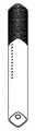
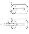
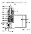
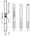
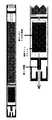
図1は、従来の個人用気化器(「PV」)を示す。PVは、以下のキー構成要素、すなわち、カートリッジ(A)と呼ぶ「ジュース(juice)」または「eリキッド(e−liquid)」送出及び容器システム、ジュースを気化させるための霧化器(B)、及び霧化器に電力供給する電力源(C)を含む。カートリッジはまた、マウスピースを形成する。図1に示す典型的な設計は、電池(C)が霧化器(B)にねじ込まれることを必要とし、カートリッジ(A)は、霧化器(B)の自由端上に押される。カートリッジが完全に消費されると、ユーザは、使用済みカートリッジを廃棄し、使用済みカートリッジを新しいカートリッジと交換する。代替の設計は、カートリッジを、通常eリキッドの小さなボトルからユーザ再充填可能であると見なす。 FIG. 1 shows a conventional personal vaporizer (“PV”). The PV is a key component of the following: a "juice" or "e-liquid" delivery and container system called a cartridge (A), an atomizer (B) for vaporizing the juice. , And a power source (C) that supplies power to the atomizer. The cartridge also forms a mouthpiece. The typical design shown in FIG. 1 requires the battery (C) to be screwed into the atomizer (B) and the cartridge (A) is pushed onto the free end of the atomizer (B). When the cartridge is completely consumed, the user discards the used cartridge and replaces the used cartridge with a new one. The alternative design considers the cartridge to be user refillable, usually from a small bottle of e-liquid.
従来のPV設計は、幾つかの欠点がある。この詳細な説明の節は、最も重要な欠点に対処する幾つかの高レベル特徴を記載する。本発明の実施態様は、これらの高レベル特徴の1つまたは複数を使用する。 Traditional PV designs have some drawbacks. This detailed description section describes some high-level features that address the most important shortcomings. Embodiments of the invention use one or more of these high level features.
以下の分類を使用して特徴の説明を構成する。
節A. eリキッド再充填及び再充電格納及びキャリングケース
特徴1.再充電及び再充填格納及びキャリングケースの組合せ物
特徴2.可動PVホルダを有するケース
特徴3.PV再充填
特徴4.PVロッキング機構
特徴5.データ接続
特徴6.e遂行
節B. PV:使用の簡単さ及び容易さ
特徴7.再充填可能でかつ再充電可能なPV
特徴8.予熱を有するPV
特徴9.用量指示を有するPV
特徴10.液だれ防止を有するPV
節C. ユーザ交換可能eリキッドカートリッジ
特徴11.携帯型格納及びキャリングケースに嵌合するユーザ交換可能eリキッドカートリッジ
節D その他
特徴12 衛生的PV
特徴13 単一カプセル分配器
特徴14 単一カプセルPV
特徴15 種々の構造上の改良The following classifications are used to construct a description of the features.
Section A. e Liquid refilling and recharging storage and carrying
Section C. User replaceable e-liquid cartridge Features 11. User replaceable to fit in a portable storage and carrying case e Liquid Cartridge Section
先に挙げた各高レベル特徴、及び、各高レベル特徴について以下で挙げる関連する詳細特徴が、任意の他の高レベル特徴、及び、任意の他の詳細特徴と組合され得ることに留意されたい。付録1は、これらのそれぞれの統合された要約を提供する。 Note that each high-level feature listed above, and the relevant detail features listed below for each high-level feature, can be combined with any other high-level feature, and any other detail feature. ..
序
以下の節は、本発明の態様を実装する電子たばこシステムを記載する。本システムは以下を含む:
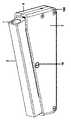
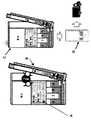
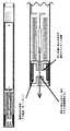
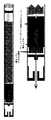
・電子たばこPV;サイズ及び形状は、従来のたばこと同様であるまたは従来のたばこよりわずかに大きくあり得る。これは図2に示される。従来のたばこのサイズ及び形状を真似ることは、たばこを止めようと試みる喫煙者に対してPVをずっと魅力的にするため、非常に役立つ。
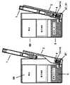
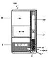
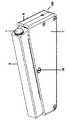
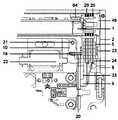
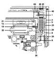
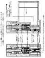
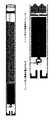
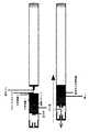
・PV内の電池を再充電すると共に、PV内のeリキッドチャンバを再充填する携帯型個人用格納及びキャリングケース;サイズ及び形状は、20本のたばこの従来のたばこ箱と同様であるまたはそれよりわずかに大きくあり得る。これは図3(PVはそのケースから部分的に引出されている)及び図4(PVはそのケースから完全に引出されている)に示される。
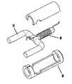
・ケースに入れられ、また、乏しくなるときにまたはeリキッドの異なる強度または香味を試すため、新鮮なカートリッジのためにユーザによって容易に交換できるユーザ交換可能カートリッジ。カートリッジ容量は、eリキッドの約10mlであることができる;これは、非常に大雑把に、20本のたばこの5箱に近いであろう。図5参照。Introduction The following sections describe e-cigarette systems that implement aspects of the invention. The system includes:
E-cigarette PV; size and shape can be similar to conventional cigarettes or slightly larger than conventional cigarettes. This is shown in FIG. Mimicking the size and shape of traditional tobacco is very helpful as it makes PV much more attractive to smokers trying to stop smoking.
Portable personal storage and carrying case that recharges the battery in the PV and refills the e-liquid chamber in the PV; similar in size and shape to a conventional cigarette box of 20 cigarettes or it Can be slightly larger. This is shown in FIG. 3 (PV is partially pulled out of the case) and FIG. 4 (PV is fully pulled out of the case).
-A user-replaceable cartridge that can be easily replaced by the user for a fresh cartridge when placed in a case and also when it becomes scarce or to test different strengths or flavors of the e-liquid. The cartridge capacity can be about 10 ml of e-liquid; this would be very roughly close to 5 boxes of 20 cigarettes. See FIG.
PVが、使用されないときはいつでもケースに格納することができ、ケースが、そのユーザ交換可能カートリッジからPVを再充填し、PVを再充電するようにも動作してもよいので、PVは、ケースから取外されるときはいつでも、その完全に再充填された状態でかつ再充電された状態に常にあることができる。PV用の予備の電池またはeリキッドの小さな再充填ボトルをユーザが持ち運ぶ必要性がもはや全く存在しない。 The PV is a case because the PV can be stored in the case whenever it is not in use and the case may also act to refill the PV from its user replaceable cartridge and recharge the PV. Whenever it is removed from, it can be in its fully refilled and recharged state at all times. There is no longer any need for the user to carry a spare battery for PV or a small refill bottle of e-liquid.
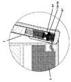
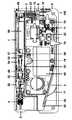
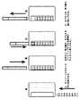
図3及び4に示すこの新しいシステムの1つの設計は、ケースの主本体から外側に蝶番式に動くホルダ内にPVが入れられ、ユーザが手動でPVを上下に押し、ケース内のユーザ交換可能カートリッジからPV内のリザーバにeリキッドを移送するマイクロポンプを作動させるとeリキッドによって自動的にPVが補充されることを有する。ホルダがケース内に閉じ込められると、PV上の電気接点は、ケース内の充電用接点に係合し、ケース電池からPV内の充電式電池に電力を伝達する。これは以下を意味する:
・PVの吸入性能が常に最適である;弱いPV電池またはほぼ空のPVeリキッドリザーバに伴う性能劣化が全く存在しない。
・PVがより低い電圧で蒸気発生することができる(おそらくは、ホルムアルデヒドの
ゼロ排出に伴う。上の関連技術の考察参照):従来のシステムにおいて、これは、霧化器内の加熱ワイヤの抵抗が十分に低い(またしたがって、全体の電力が、十分であるが、高過ぎない、通常、6〜8ワット帯にある)ときに良好な吸入体験を提供することができるが、高い電池消耗及び高いeリキッド消費という深刻な欠点をもたらす。これらの欠点は、格納及びキャリングケースを使用してPVを再充填すると共に再充電するという容易さのために、ここで、新しいシステムには完全に無関係となる。
・格納ケースが携帯型個人用格納及びキャリングケース(通常、20本のたばこの1箱とサイズが同様である)であるように設計されるため、ユーザは、一般に、ケースを常に(ポケットまたはハンドバッグ等に入れて)持ち運び、したがって、PVを常にケースに格納することになる。格納ケースは、従来のPVよりかなり大きいため、そのユーザ交換可能eリキッドカートリッジ内に一層多くのeリキッドを格納することができ、また、ずっと大きな容量の電池を含むことができる。したがって、キャリングケース内のeリキッドカートリッジは、比較的低頻度で交換される必要があるだけである(このシステムに切換える1日に通常20本のたばこを吸う喫煙者の場合、そうすることにより新しいカートリッジは5日ごとに必要とされるであろう:非常に大雑把に、10回の吸入はeリキッドの0.1mlまたは1本のたばこと同等量を消費し;PV自体は、通常、eリキッドの2mlまたは20本のたばこと同等量を格納し;ケース内のカートリッジは、通常、EU指令2014/40/EU(タバコ製品指令として知られる)に適合するためeリキッドの約10mlまたは20本のたばこの5箱の同等量を格納する。更に、ケースは、同様に低頻度で(おそらく、使用法に応じて1週間に1回)(例えば、ラップトップまたは主電力アダプタに接続されたUSB充電用ケーブルを使用して)再充電される必要があるだけである。One design of this new system, shown in FIGS. 3 and 4, is that the PV is placed in a holder that hinges outward from the main body of the case, allowing the user to manually push the PV up and down and replace the user inside the case. The e-liquid automatically replenishes the PV when a micropump that transfers the e-liquid from the cartridge to the reservoir in the PV is operated. When the holder is confined in the case, the electrical contacts on the PV engage the charging contacts in the case and transfer power from the case battery to the rechargeable battery in the PV. This means:
PV inhalation performance is always optimal; there is no performance degradation associated with weak PV batteries or near empty PVe liquid reservoirs.
PV can steam at lower voltages (probably with zero emission of formaldehyde; see related technology discussion above): In conventional systems, this is due to the resistance of the heating wire in the atomizer. It can provide a good inhalation experience when low enough (and therefore the overall power is sufficient but not too high, usually in the 6-8 watt band), but with high battery consumption and high It brings the serious drawback of e-liquid consumption. These drawbacks are now completely irrelevant to the new system due to the ease of refilling and recharging the PV using a storage and carrying case.
• Users generally always keep the case (pocket or purse) because the storage case is designed to be a portable personal storage and carrying case (usually similar in size to a box of 20 cigarettes). Carry it (in a case, etc.) and therefore always store the PV in the case. Since the storage case is considerably larger than the conventional PV, more e-liquid can be stored in the user replaceable e-liquid cartridge and can also contain a much larger capacity battery. Therefore, the e-liquid cartridge in the carrying case only needs to be replaced relatively infrequently (for smokers who normally smoke 20 cigarettes a day switching to this system, doing so is new. Cartridges will be needed every 5 days: very roughly, 10 inhalations consume 0.1 ml of e-liquid or the equivalent of a cigarette; PV itself is usually
このシステムは、ケースにもPVにも損傷を与えることなく、何千回もPVを再充填し再充電するように設計される。このシステムは、ユーザに、従来のたばこのフォームファクタ、及び、大きなモッディングキット型PVの性能及びユーザ体験(例えば、蒸気強度)を有する電子たばこPVを与えるが、小さなボトルからのeリキッドでPVを再充填するためPVを分解するという不都合を全く与えない。このシステムは、また20本のたばこの1箱とサイズが同様である物体を手にし、その箱を開口し、たばこを引出すという儀式、並びに、たばこサイズの物体を手に持ち、その物体から吸引するという触知可能な親しみ易さを再現する。この組合せは、電子たばこの大規模消費者採用にとっての重要点であると本発明者等は考える。 The system is designed to refill and recharge the PV thousands of times without damaging the case or the PV. This system gives the user an e-cigarette PV with a traditional tobacco form factor and the performance and user experience (eg vapor intensity) of a large modding kit PV, but with e-liquid from a small bottle PV. It does not give any inconvenience of decomposing PV because it is refilled. The system also holds an object that is similar in size to a box of 20 cigarettes, opens the box and pulls out the cigarette, as well as holding a cigarette-sized object in hand and sucking from that object. Reproduce the tactile familiarity of doing. The present inventors consider that this combination is an important point for large-scale consumer adoption of electronic cigarettes.
節A. eリキッド再充填及び再充電格納及びキャリングケースSection A. e Liquid refilling and recharging storage and carrying case
この節Aにおいて、eリキッド再充填及び再充電格納及びキャリングケースを記載する。ケースは、幾つかの有用な特徴を実現する:
特徴1.再充電及び再充填格納及びキャリングケースの組合せ物
特徴2.可動PVホルダを有するケース
特徴3.PV再充填
特徴4.PVロッキング機構
特徴5.データ接続
特徴6.e遂行Section A describes e-liquid refilling, recharging storage and carrying cases. The case realizes some useful features:
この節Aにおいて、これらの6つの特徴のそれぞれを順に要約し、その後、それらを詳細に記載する。付録1は、これらの特徴を収集して統合した要約にする。 In this section A, each of these six features will be summarized in turn and then described in detail.
特徴1.再充電及び再充填格納及びキャリングケースの組合せ物
この特徴は、eリキッド電子たばこPV用の携帯型個人用格納及びキャリングケースで
あり、ケースは、(a)PV内の充電式電池を再充電するための電力源と、(b)eリキッドを維持するためのリザーバと、(c)リザーバからPV内のチャンバにeリキッドを移送するように適合される液体移送システムとを含む。eリキッドを維持するためのリザーバは、一実施態様において、ユーザ交換可能eリキッドカートリッジである。This feature is a portable personal storage and carrying case for e-liquid e-cigarette PV, which provides (a) a power source for recharging the rechargeable battery in the PV and (b) e-liquid. It includes a reservoir for maintenance and (c) a liquid transfer system adapted to transfer the e-liquid from the reservoir to the chamber in the PV. The reservoir for maintaining the e-liquid is, in one embodiment, a user replaceable e-liquid cartridge.
上で述べたように、このアプローチは、従来のたばこのフォームファクタ、及び、大きなモッディングキット型PVの性能及びユーザ体験を有する電子たばこPVにとっての重要点であり:PVの再充填及び再充電は、ユーザがPVをそのケースに戻すときはいつでも、即座にかつ容易に起こることができるので、迅速かつ好都合である。ケース内のeリキッドカートリッジは、比較的低頻度である(例えば、毎週)が、迅速でかつ混乱がない交換を必要とし;交換は、小さなボトルからeリキッドを絞り出すことによる手動の再充填よりずっと容易である。交換は、また従来のたばこ(例えば、「ケース内の100本のたばこ」)消費と単純な関係を有する。 As mentioned above, this approach is important for e-cigarette PV with traditional tobacco form factor and large modding kit PV performance and user experience: PV refilling and recharging. Is quick and convenient because it can happen immediately and easily whenever the user returns the PV to the case. The e-liquid cartridges in the case are relatively infrequent (eg weekly) but require quick and unconfused replacement; replacement is much more than manual refilling by squeezing the e-liquid from a small bottle. It's easy. The exchange also has a simple relationship with conventional tobacco consumption (eg, "100 cigarettes in a case").
PV電池を再充電し、PVのeリキッドチャンバを再充填するという2つの特徴が、改善された全体的結果を生じる、作動相互関係を有することに同様に留意されたい。例えばUS6637430 Ponwellによって例示された定量吸入器の非類似分野において完全に欠けている、相乗的な特徴の組合せを有する。 It should also be noted that the two features of recharging the PV battery and refilling the PV e-liquid chamber have working interrelationships that produce improved overall results. It has a combination of synergistic features that is completely lacking in the dissimilar field of metered dose inhalers exemplified by, for example, US66337430 Ponwell.
特に、効果的なeリキッドPVは、かなりの量のeリキッドまた同様に電流を消費する。シガライトは、高いeリキッド消費も高い電流も可能にしないため、市場において十分に売れなかった。単にPVを再充電することができるケースは、十分に良好でない。その理由は、PVがeリキッドによって頻繁に再充填される必要があり、それが、ケースを分解することを意味し、混乱を招きかつ不都合である。しかし、この特徴1によって想定されるように、eリキッド再充填特徴がケースに付加されると、それは、ずっと良好な性能を与えるのに十分に高い電流でPV内の加熱要素が動作することを意味し、加熱要素がより急速に加熱されるためここでより多くのeリキッドが消費されるが、PV電池がここでより急速に枯渇していることは、もはや問題とはならない。その理由は、PVがキャリングケースに元通り挿入されると、eリキッドによってPVが好都合に再充填されると共に、PV電池が再充電されるからである。eリキッドPV再充填能力をそのように付加することは、PV電池再充電機能と作動相互関係を有する。それは、PVが、より高い電流で、また、より高いジュース消費率で動作することを可能にし、ずっと良好な吸入性能を与えるが、再充填または電池交換のためにPVを定期的に分解しなければならないという不都合はない。 In particular, effective e-liquid PV consumes a significant amount of e-liquid and similarly current. Cigarite did not sell well in the market because it does not allow for high e-liquid consumption or high current. The case where the PV can simply be recharged is not good enough. The reason is that PV needs to be frequently refilled with e-liquid, which means disassembling the case, which is confusing and inconvenient. However, as envisioned by this
また、この特徴1に関して、霧化器内で低抵抗ワイヤが使用される場合、おそらくホルムアルデヒドを全く生成しない可能性が高いより低い電圧(例えば、3.3V)で霧化器が動作され得、これは、ホルムアルデヒドを全く生成しないだけでなく、デバイスが5Vで動作している場合に作られることになるより暖かい蒸気及びより多くの蒸気もまた生成する。 Also, with respect to this
再充填キャリングケース及び再充電キャリングケースの組合せ物を持たないシステムは、3.3Vのようなより低い電圧でこの体験を再現することはできない。その理由は、3.3V及び低抵抗ワイヤの組合せが、より高い電圧及びより高い抵抗のワイヤの組合せに比べて、急速な電池消耗及び急速なeリキッド消費を意味するからである。上に述べたように、より急速な電池消耗及びより急速なeリキッド消費は、特徴1の場合、欠点ではない。その理由は、PVを再充電し、eリキッドでPVを再充填することは、急速でかつ好都合であり、PVが格納及びキャリングケースに戻されるときにいつでも即座に起こることができるからである。 Systems without a combination of refill carrying case and recharging carrying case cannot reproduce this experience at lower voltages such as 3.3V. The reason is that the combination of 3.3V and low resistance wire means faster battery consumption and faster e-liquid consumption than the combination of higher voltage and higher resistance wire. As mentioned above, faster battery drain and faster e-liquid consumption are not drawbacks for
特徴2.可動PVホルダを有するケース
この特徴は、eリキッド電子たばこPV用の携帯型個人用格納及びキャリングケースであり、可動ホルダまたはシャシであって、可動ホルダまたはシャシにPVが挿入される、可動ホルダまたはシャシを移動させることは、PV上の充電用接点を、ケース内の充電式電池等の電力源に接続されるケース内の充電用接点と直接的または間接的係合状態になるようにもたらす。 This feature is a portable personal storage and carrying case for e-liquid e-cigarette PV, which is a movable holder or chassis, in which the PV is inserted into the movable holder or chassis, the movable holder or chassis can be moved. , The charging contacts on the PV are brought into direct or indirect engagement with the charging contacts in the case connected to a power source such as a rechargeable battery in the case.
ケース内の可動ホルダまたはシャシにPVが挿入されることを要求することによって、ケース内の充電用接点と正確なアライメント状態になるようPVを誘導すること、並びに、(好ましくは)eリキッドをPV内に移送するために使用されるeリキッドノズルと正確なアライメント状態になるようPV内のeリキッド充填アパーチャを誘導することがずっと容易になる。正確なアライメントは、良好な電気接触を保証し、漏洩を最小にし、eリキッド液体移送機構の最適性能を保証するために非常に望ましい。 By requiring the PV to be inserted into the movable holder or chassis inside the case, the PV is guided to be in a precise alignment with the charging contacts inside the case, and (preferably) the e-liquid is PV. It is much easier to guide the e-liquid filling aperture in the PV so that it is in accurate alignment with the e-liquid nozzle used to transfer it in. Accurate alignment is highly desirable to ensure good electrical contact, minimize leakage and ensure optimum performance of the e-liquid liquid transfer mechanism.
特徴3.PV再充填
この特徴は、PVを完全でかつ無傷のままに維持しながら、PVがケースに完全にまたは部分的に挿入される場合、eリキッドでPVを再充填する、eリキッド電子たばこPV用の携帯型個人用格納及びキャリングケースである。 This feature is portable for e-liquid e-cigarette PV, which refills PV with e-liquid when PV is completely or partially inserted into the case while keeping PV complete and intact. Personal storage and carrying case.
PVが完全に無傷のままであることを保証することによって(例えば、医療液体を格納するキャニスタ内の針が、吸入デバイス内のゴム隔壁を穿刺することを要求する一部の医療用吸入デバイスと対照的に)、設計は、頑健であり、また、(ゴム隔壁を穿刺する針の場合の非常に少ない数と対照的に)何千もの再充填動作のために使用され得る。 By ensuring that the PV remains completely intact (eg, with some medical inhalation devices that require the needle in the canister containing the medical liquid to puncture the rubber bulkhead in the inhalation device. In contrast, the design is robust and can also be used for thousands of refilling operations (as opposed to the very small number of needles that puncture rubber bulkheads).
別の関連する高レベル特徴は、液体移送機構との正確なアライメント状態で、ケースのホルダ内にPVが維持されている間に、全体で完全なPVを押下し、解除することによって作動されるポンプ等の液体移送システムを使用してPVを再充填する、eリキッド電子たばこPV用の携帯型個人用格納及びキャリングケースである。 Another relevant high level feature is activated by pressing and releasing the entire complete PV while the PV is maintained in the holder of the case in a precise alignment with the liquid transfer mechanism. A portable personal storage and carrying case for e-liquid e-cigarette PV that refills PV using a liquid transfer system such as a pump.
液体移送システムとの正確なアライメント状態でPVを維持するためにホルダを使用することは、漏洩を最小にし、また、特に、eリキッド液体移送機構が、ポンプに対するPVの相対的運動によって作動されるポンプである場合、eリキッド液体移送機構の最適性能を保証するために非常に望ましい。その理由は、PVが正しく(例えば、ポンプノズルの長手方向軸に沿って)整列していない場合、ポンプが、効率的に動作しない場合があり、また、漏洩が存在する場合があるからである。 Using the holder to maintain the PV in a precise alignment with the liquid transfer system minimizes leakage and, in particular, the e-liquid liquid transfer mechanism is actuated by the relative movement of the PV with respect to the pump. If it is a pump, it is highly desirable to guarantee the optimum performance of the e-liquid liquid transfer mechanism. The reason is that if the PVs are not aligned correctly (eg, along the longitudinal axis of the pump nozzle), the pump may not operate efficiently and there may be leaks. ..
関連する高レベル特徴は、ケースに挿入されると、eリキッドで再充填されるように適合されたeリキッド電子たばこPVであり、PVは、PVの主軸に沿って中心に位置づけられたeリキッド充填アパーチャを含んで、それ以外ではeリキッドシーリングを低下させる可能性がある中心をはずれたどんな力も最小にする。 A related high-level feature is the e-liquid e-cigarette PV, which is adapted to be refilled with e-liquid when inserted into the case, the PV being centered along the principal axis of the PV. Minimizes any off-center force that would otherwise reduce e-liquid sealing, including the filling aperture.
別の関連する高レベル特徴は、eリキッド電子たばこPV用の携帯型個人用格納及びキャリングケースであり、ケースは、電子たばこPVからケース内のユーザ交換可能eリキッドカートリッジにeリキッドを移送するように適合される。 Another relevant high-level feature is the portable personal storage and carrying case for e-liquid e-cigarette PV, where the case transfers e-liquid from the e-cigarette PV to a user-replaceable e-liquid cartridge in the case. Is adapted to.
ケースがユーザ交換可能カートリッジを含む場合、ケースは、ユーザが、ユーザカートリッジを交換し、また、カートリッジを入れ替えることによってeリキッドの新しい香味または強度を試みるために迅速でありかつ混乱がなくなる。カートリッジ容量が、PVの
eリキッドチャンバよりずっと大きいことになるため(例えば、PVチャンバ内の1または2mlと比較してユーザ交換可能カートリッジの場合10ml)、カートリッジの交換は、比較的低頻度で起こり、1日20本のたばこを喫煙することを再現するユーザの場合、通常、5日ごとに1回起こる。それは、また、ユーザが従っている任意のニコチン低減プログラム、5日ごとにカートリッジを交換することから、6日ごとに交換すること、7日ごとに交換すること等へと、徐々に移っていくこと等の効果の尺度を把握する容易さをユーザに与える。多くの普通のユーザにとって、これは、従うべき容易な評価基準である。If the case contains a user replaceable cartridge, the case is quick and unconfusing for the user to try a new flavor or strength of the e-liquid by replacing the user cartridge and also replacing the cartridge. Cartridge replacement occurs relatively infrequently because the cartridge capacity will be much larger than the PV e-liquid chamber (eg, 10 ml for user replaceable cartridges compared to 1 or 2 ml in the PV chamber). For users who recreate
特徴4.PVロッキング機構
この特徴は、PVを充電位置に確実にロックするように適合される、eリキッド電子たばこPV用の携帯型個人用格納及びキャリングケースであり、PVが充電位置にロックされると、PV上の充電用接点は、ケース内の充電式電池等の電力源に接続されるケース内の充電用接点と直接的または間接的係合状態になる。 This feature is a portable personal storage and carrying case for e-liquid e-cigarette PV that is adapted to securely lock the PV to the charging position, and when the PV is locked to the charging position, it is on the PV. The charging contact is in a direct or indirect engagement state with the charging contact in the case connected to a power source such as a rechargeable battery in the case.
PVが所定の位置にロックされることを保証することによって、効果的な充電が起こることができ、また、PVの意図しない移動による(PV上とケース内の両方の)電気接点に損傷を与えるリスクが減少する。これは、ケースが携帯型格納及びキャリングケースであるため特に重要である。 By ensuring that the PV is locked in place, effective charging can occur and also damage the electrical contacts (both on the PV and in the case) due to unintended movement of the PV. Risk is reduced. This is especially important because the case is a portable storage and carrying case.
特徴5.データ接続を有するケース
この特徴は、eリキッド電子たばこPV用の携帯型個人用格納及びキャリングケースであり、ケースは、(a)ユーザ交換可能eリキッドカートリッジと、(b)カートリッジからPV内のチャンバにeリキッドを移送するように適合される液体移送システムとを含み、ケースは、ケース内のユーザ交換可能eリキッドカートリッジについて交換を要求する信号を送信することを制御するデータプロセッサを含む。 This feature is a portable personal storage and carrying case for e-liquid e-cigarette PV, which is (a) a user-replaceable e-liquid cartridge and (b) transfers the e-liquid from the cartridge to the chamber in the PV. The case includes a data processor that controls sending a signal requesting replacement for a user replaceable e-liquid cartridge in the case, including a liquid transfer system adapted to.
交換eリキッドカートリッジについての要求をケースが送信することを可能にすることは、ユーザにとって非常に好都合であり、また交換カートリッジが適時な方法で供給されることを保証し、これは、ユーザがタバコまたはニコチン低減プログラムを受けているときに特に重要であり、その理由は、ケースがeリキッドを使い果たす場合、ユーザが、元通りにたばこを使用したい誘惑にかられる場合があるためである。そのため、たばこの代替としてこのシステムを採用する(たばこに関する健康の懸念が、圧倒的に電子たばこ採用について与えられる理由である)効果は、適時で自動的でバックグラウンドの交換カートリッジのオーダリング及び交換カートリッジのエンドユーザに対する直接の供給によって著しく利益を与える。 Allowing the case to send a request for a replacement e-liquid cartridge is very convenient for the user and also ensures that the replacement cartridge is delivered in a timely manner, which allows the user to cigarette. Or it is especially important when undergoing a nicotine reduction program, because if the case runs out of e-liquid, the user may be tempted to use the cigarette again. Therefore, the effect of adopting this system as an alternative to tobacco (which is why tobacco health concerns are overwhelmingly given to e-cigarette adoption) is timely and automatic background ordering and replacement cartridges. Significantly benefit from direct supply to end users.
特徴6.e遂行
この高レベル特徴は、再充填可能電子たばこPVのために特に適合され、かつ、PVを再充填し再充電する携帯型個人用格納及びキャリングケースにおいて使用される方法であり、方法は、(a)ケースが、eリキッドをユーザ交換可能eリキッドカートリッジからPVに移送するステップと、(b)ケースが、ユーザ交換可能eリキッドカートリッジについての交換を要求する信号をe遂行プラットフォームに直接にまたは接続されたスマートフォンによって自動的に送信するステップとを含む。方法は、(a)ケースがケース内のユーザ交換可能eリキッドカートリッジ内のeリキッドのレベルまたは量を検出するステップと、(b)ケースがユーザ交換可能eリキッドカートリッジについての交換を要求する信号をe遂行プラットフォームに直接にまたは接続されるスマートフォンによって自
動的に送信するステップとを含む。This high level feature is specifically adapted for refillable e-cigarette PV and is the method used in portable personal storage and carrying cases to refill and recharge PV, the method is (a). ) The case transfers the e-liquid from the user-replaceable e-liquid cartridge to the PV, and (b) the case is directly or connected to the e-execution platform with a signal requesting replacement for the user-replaceable e-liquid cartridge. Includes steps to automatically send by your smartphone. The method is: (a) the case detects the level or amount of e-liquid in the user-replaceable e-liquid cartridge in the case, and (b) the case signals a request for replacement of the user-replaceable e-liquid cartridge. e Includes steps to send automatically by a smartphone directly or connected to the performance platform.
この特徴は、特徴5に関連する方法であり、同じ利点が当てはまる。「ケース内のユーザ交換可能eリキッドカートリッジ内のeリキッドのレベルまたは量を検出すること」が、直接的である可能性がある、または、そのカートリッジに関して終了されたPVの再充填の回数またはそのカートリッジに関して行われた吸引の総数から推測されるように、間接的である可能性があることに留意されたい。 This feature is a method related to
更なるオプションの特徴(それぞれは、先の他の高レベル特徴1〜6の任意の特徴と組み合わせることができる)は、以下を含む:
・可動シャシは、可動シャシ上に搭載された、eフルイドリザーバ、電池、プリント回路板、及び液体移送機構も有する。
・eリキッドの計量済み用量または量が、ケース内の液体移送機構によってPVに送出され、マイクロポンプが使用される個々の圧送動作について通常0.1mlである。
・携帯型再充填ケースまたはユニットは、個人用気化器を収容する、固定する、または個人用気化器に係合するためのホルダを備える。
・ホルダは、維持位置で個人用気化器を受取るための付勢手段を備え、付勢手段は、ユーザが個人用気化器を押下することが、個人用気化器が再充填位置で再充填機構に係合することを可能にするよう付勢手段にさせるように配置される。
・ホルダは、開口構成と閉鎖構成との間で移動できるように携帯型再充填ユニットに回転可能に接続され得、開口構成及び閉鎖構成は、対応する個人用気化器位置を有し、閉鎖構成において、個人用気化器は再充填機構に係合して、或る用量の物質を受取り、開口構成において、個人用気化器は再充填機構から係脱する。
・再充填機構はポンプを備える。
・再充填機構は再充填弁を備える。
・再充填機構は電子制御される。
・携帯型再充填ケースは、個人用気化器が液体リザーバから再充填された回数等の物質消費関連データを計数または推定するためのカウンタ/測定システムを更に備える。
・カウンタ/測定システムは、個人用気化器が再充填のためにユニットに挿入された回数を計数する。
・カウンタ/測定システムは、リセット可能であり、携帯型再充填ユニットは、個人用気化器が液体リザーバから再充填された回数に対応する、カウンタ/測定システムによって提供される値を格納及び/または表示する。
・カウンタ/測定システムは、ユニットに格納される物質の量の変化を測定することによって消費関連データを直接測定する。
・携帯型再充填ケースまたはユニットは、消費関連データを格納し、そのデータを無線または非無線接続を使用してスマートフォン等の別のデバイスに送信する。
・液体リザーバは、交換できるように、携帯型再充填ユニットから取外し可能である液体カートリッジである。
・携帯型再充填ケースまたはユニットは、蒸気液体の量を蒸気液体の被送出用量内で修正するように更に適合される。Additional optional features, each of which can be combined with any of the other high-level features 1-6 above, include:
-The movable chassis also has an e-fluid reservoir, a battery, a printed circuit board, and a liquid transfer mechanism mounted on the movable chassis.
A weighed dose or amount of e-liquid is typically 0.1 ml for each pumping operation in which a micropump is used, delivered to PV by a liquid transfer mechanism within the case.
• The portable refill case or unit comprises a holder for accommodating, fixing, or engaging the personal vaporizer.
-The holder is provided with an urging means for receiving the personal vaporizer at the maintenance position, and the urging means allows the user to press the personal vaporizer, and the personal vaporizer is refilled at the refilling position. Arranged to cause urging means to allow engagement with.
The holder may be rotatably connected to the portable refill unit so that it can be moved between the open and closed configurations, and the open and closed configurations have the corresponding personal vaporizer positions and the closed configurations. In, the personal vaporizer engages the refill mechanism to receive a dose of material, and in an open configuration, the personal vaporizer engages and disengages from the refill mechanism.
-The refill mechanism is equipped with a pump.
-The refill mechanism is equipped with a refill valve.
-The refilling mechanism is electronically controlled.
The portable refill case further comprises a counter / measurement system for counting or estimating material consumption related data such as the number of times the personal vaporizer has been refilled from the liquid reservoir.
The counter / measurement system counts the number of times a personal vaporizer has been inserted into the unit for refilling.
The counter / measurement system is resettable and the portable refill unit stores and / or the values provided by the counter / measurement system that correspond to the number of times the personal vaporizer has been refilled from the liquid reservoir. indicate.
• The counter / measurement system directly measures consumption-related data by measuring changes in the amount of substance stored in the unit.
• The portable refill case or unit stores consumption-related data and transmits that data to another device, such as a smartphone, using a wireless or non-wireless connection.
The liquid reservoir is a liquid cartridge that can be removed from the portable refill unit for replacement.
• The portable refill case or unit is further adapted to modify the amount of vapor liquid within the delivery dose of vapor liquid.
節Aの次の節において、以下の特徴の動作を詳述する。
特徴1: 再充電及び再充填格納及びキャリングケースの組合せ物
特徴2: 可動PVホルダを有するケース
特徴3: PV再充填
特徴4: PVロッキング機構In the next section of Section A, the operation of the following features will be described in detail.
Feature 1: Combination of recharge and refill storage and carrying case Feature 2: Case with movable PV holder Feature 3: PV refill Feature 4: PV rocking mechanism
特徴1、2、3、及び4. 再充電及び再充填格納及びキャリングケースの組合せ物;
可動PVホルダを有するケース;
PV再充填;
PVロッキング機構
Case with movable PV holder;
PV refilling;
PV rocking mechanism
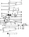
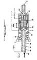
以下の節は、これらの4つの特徴に的を絞りながら、ケース及びPVをより詳細に記載する。関連する図は図6〜10である。 The following sections describe the case and PV in more detail, focusing on these four features. Related figures are FIGS. 6-10.
電子たばこPVのeリキッドまたは蒸気液体を補充するための携帯型充電デバイスは、eリキッドの複数用量を格納するためのeリキッドリザーバと、電子たばこPVに係合して、或る用量のeリキッドをリザーバから電子たばこPVに送出するように構成される再充填機構とを備える。 A portable charging device for replenishing e-cigarette PV e-liquids or vapor liquids engages with e-cigarette PV with an e-liquid reservoir for storing multiple doses of e-liquid and a dose of e-liquid. Is provided with a refilling mechanism configured to deliver the e-cigarette PV from the reservoir.
実施形態は、(エンドユーザによって予め決定された)1回用量または複数用量のeリキッドで電子たばこPVを再充填するための再充填ケースを提供してもよい。eリキッドは、eリキッドの大きな貯蔵部を維持する充電及び再充填ケース内のタンクから電子たばこPVに供給されてもよい。タンクはユーザ交換可能カートリッジであってよい。 Embodiments may provide a refill case for refilling e-cigarette PV with a single dose or multiple doses of e-liquid (predetermined by the end user). The e-liquid may be supplied to the e-cigarette PV from a tank in a charging and refilling case that maintains a large reservoir of e-liquid. The tank may be a user replaceable cartridge.
PVに送出される(そして、その後、PV内のeリキッドチャンバ内で維持される)eリキッドの1回用量は、物質の単一測定値(普通の1つのたばこ内で吸入されるニコチンの量等)と同等であってよい。通常、本節において後で記載するマイクロポンプ設計を使用して、各圧送動作によって0.1mlが送出される:これは、1本のたばこの約10服と同等である。PV内のeリキッドチャンバは、通常、非常に大雑把に、10〜30本のたばこと同等の、1mlと3mlとの間のeリキッドを維持する。 A single dose of e-liquid delivered to the PV (and subsequently maintained in the e-liquid chamber within the PV) is a single measurement of the substance (the amount of nicotine inhaled in a normal single cigarette). Etc.) may be equivalent. Generally, using the micropump design described later in this section, each pumping operation delivers 0.1 ml: this is equivalent to about 10 cigarettes per cigarette. The e-liquid chamber in the PV usually maintains an e-liquid between 1 ml and 3 ml, which is equivalent to 10 to 30 cigarettes, very roughly.
充電及び再充填ケース内の液体リザーバは、複数用量のeリキッドを格納してもよい:リザーバに格納されるeリキッドの量は、10ml、したがって、従来の電子たばこに挿入される従来のカートリッジまたはバイアル内の液体より著しく多くあり得る。これは、新鮮なeリキッドカートリッジによってケースを再充填することをより低頻度にする;従来のPVの場合、PV内のカートリッジは、比較的小さな用量が消費されると補充または交換されなければならない;本発明者等のアプローチの場合、交換されなければならないのは、キャリングケースに入れられるカートリッジであり、これは、即座に行われる;これが、従来のPVカートリッジより一層多くを維持するため、交換はずっと低頻度で起こる。PVの再充填は、ユーザがPVを元通りキャリングケースに挿入するときはいつでも、容易にかつ迅速に起こる。これは、エンドユーザにとって好都合であるだけでなく、廃棄物を著しく減少させる。カートリッジは、理想的には、完全に再利用可能である。 The liquid reservoir in the charging and refilling case may contain multiple doses of e-liquid: the amount of e-liquid stored in the reservoir is 10 ml, thus a conventional cartridge or a conventional cartridge inserted into a conventional e-cigarette. It can be significantly more than the liquid in the vial. This makes refilling the case less frequently with fresh e-liquid cartridges; in the case of conventional PV, the cartridges in the PV must be refilled or replaced when a relatively small dose is consumed. In the case of our approach, it is the cartridge that must be replaced that is placed in the carrying case, which is done immediately; because it maintains more than the conventional PV cartridge, it is replaced. Occurs much less frequently. PV refilling occurs easily and quickly whenever the user reinserts the PV into the carrying case. Not only is this convenient for the end user, but it also significantly reduces waste. The cartridge is ideally completely reusable.
容易にユーザ交換可能である高容量のeリキッドカートリッジは、PVによるeリキッド消費が非常に高い可能性があるため、比較的低電圧、低抵抗(例えば、5Vより3.3Vに近い;2.8オーム以上の値より2オームに近い抵抗−通常、2.4オーム−3.3Vの場合、1.9オーム)において特に重要である。この高い消費は、従来のPV設計の場合、PVを分解し、eリキッドのボトルを絞り出すことによって小さなリザーバ内にeリキッドを手動で滴下する必要性があるため、非常に不都合である。しかし、PVが元通りケースに入れられるときはいつでも、eリキッドでPVを再充填するのが容易であるため、それはもはや問題とならない。 High capacity e-liquid cartridges that are easily user replaceable have relatively low voltage and low resistance (eg, closer to 3.3V than 5V; 2. It is especially important for resistors closer to 2 ohms than values above 8 ohms-usually 2.4 ohms-1.9 ohms for 3.3 V). This high consumption is very inconvenient in the case of conventional PV designs, as it requires the e-liquid to be manually dropped into a small reservoir by decomposing the PV and squeezing out a bottle of e-liquid. However, it is no longer a problem as it is easy to refill the PV with e-liquid whenever the PV is put back in the case.
ユーザは、同様にここで、従来のたばこ消費と同様な方法でPVの使用(したがって、ニコチン使用)をモニターできる。例えば、1回用量は、単一のタバコ葉のたばこと同等のニコチン消費をシミュレートするために必要とされるeリキッドの量と同等であってもよい。本節において後で記載するマイクロポンプシステムの場合、マイクロポンプに当てて1回だけPVを下に押すことは、約0.1mlをケースからPVに移送させる;これは、1本のたばこの10服とほぼ同等である。したがって、ユーザは、PVを1回だけ下に
押して、単一のたばこと同等のeリキッド、または例えば5本のたばこの場合5回、または10本のたばこの場合10回押すことができる。The user can also monitor the use of PV (and thus the use of nicotine) here in a manner similar to conventional tobacco consumption. For example, a single dose may be equivalent to the amount of e-liquid required to simulate the tobacco-equivalent nicotine consumption of a single tobacco leaf. In the case of the micropump system described later in this section, pressing the PV down only once against the micropump transfers about 0.1 ml from the case to the PV; this is 10 doses of one cigarette. Is almost the same as. Thus, the user can push the PV down only once to push the e-liquid equivalent to a single cigarette, or, for example, 5 times in the case of 5 cigarettes, or 10 times in the case of 10 cigarettes.
1つの設計において、PVチャンバに格納されるeリキッドの体積は、電子たばこが20本のタバコ葉のたばこの1箱をシミュレートするために必要とされるeリキッドの体積と同等であってよい。したがって、ユーザは、PVによってニコチンの消費を好都合に調節でき得る。PV内のeリキッドチャンバの最大容量は、2mlであり、したがって、20本のたばことほぼ同等であり得る。従来のたばこに対するこの理解するのが容易な同等物は、ユーザがユーザの使用量を計測することを可能にすることにおいて重要であり、したがって、ニコチン低減使用法にとって重要である;ユーザは、従来の電子たばこの使用量を過去のタバコ消費に関連付けることが難しいことを見出し、この透明性の欠如が、電子たばこが従来のたばこよりきわめてかなり安全であると見なす科学的意見のかなりの部分があるにもかかわらず、電子たばこの広範な採用を妨げる。 In one design, the volume of e-liquid stored in the PV chamber may be equivalent to the volume of e-liquid required for an e-cigarette to simulate a box of 20 tobacco leaf tobacco. .. Therefore, the user can conveniently regulate the consumption of nicotine by PV. The maximum capacity of the e-liquid chamber in the PV is 2 ml and can therefore be approximately equivalent to 20 cigarettes. This easy-to-understand equivalent to traditional tobacco is important in allowing users to measure their usage, and is therefore important for nicotine-reducing usage; users traditionally Finding that it is difficult to relate e-cigarette usage to past tobacco consumption, this lack of transparency is a significant part of the scientific opinion that e-cigarettes are much safer than traditional cigarettes. Nevertheless, it hinders the widespread adoption of e-cigarettes.
1回用量は、また例えば、エンドユーザによって、或は、例えば、エンドユーザがニコチン低減プログラムに従っている場合、PVまたはそのケースによって自動的に、1回用量と同等であるとしてセットされた任意の他の量であってよい。この一般化は、本明細書全体を通して、また、本明細書で記載する種々の革新的特徴の全てに当てはまる。 The single dose may also be, for example, by the end user, or, for example, if the end user is following a nicotine reduction program, any other automatically set as equivalent to the single dose by PV or its case. May be the amount of. This generalization applies throughout the specification and to all of the various innovative features described herein.
実施形態は、充電式ケース電池を提供してもよく、携帯型充電及び再充填ケースは、PVが、充電式ケース電池からその電池を再充電することを可能にするように適合される。携帯型充電及び再充填ケースは、ユーザが、同時に、eリキッドでPVを再充填し、PVの電池を再充電できる利点を提供してもよい。これは、PVがケースから引出されるときはいつでも、PVが良好な吸入体験を提供するのに十分なeリキッド及び電力を有することができることを保証する。 Embodiments may provide a rechargeable case battery, the portable charging and refilling case being adapted to allow PV to recharge the battery from the rechargeable case battery. The portable charging and refilling case may provide the advantage that the user can simultaneously refill the PV with the e-liquid and recharge the PV battery. This ensures that the PV can have sufficient e-liquid and power to provide a good inhalation experience whenever the PV is withdrawn from the case.
携帯型充電及び再充填ケースは、PVを収容するためのPVホルダを備えてもよい。ホルダは、PVを特定の位置に保持し、格納部を提供し、PVの再充填及び充電を可能にしてもよい。 The portable charging and refilling case may include a PV holder for accommodating PV. The holder may hold the PV in a particular position, provide a reservoir, and allow the PV to be refilled and charged.
PVホルダは、PVを保持位置で受取るための付勢手段を備えてもよい。付勢手段は、PVを押下することが、PVが再充填位置で再充填機構に係合することを可能にするよう付勢手段にさせるように配置されてもよい。或る用量の蒸気液体でPVを再充填するため、PVは、ホルダに挿入されてもよい。ホルダは、PVが引出し内に設置されると、PVを下に押すことが、PVが再充填機構に係合することを可能にするため、eリキッドがPV内に圧送され、PVのeリキッドチャンバを1回用量のeリキッドで充填するような、引出しであってよい。 The PV holder may be provided with urging means for receiving the PV at the holding position. The urging means may be arranged so that pressing the PV causes the urging means to allow the PV to engage the refilling mechanism at the refilling position. The PV may be inserted into the holder to refill the PV with a dose of vapor liquid. The holder pushes the PV down once the PV is installed in the drawer, allowing the PV to engage the refill mechanism so that the e-liquid is pumped into the PV and the PV e-liquid The drawer may be such that the chamber is filled with a single dose of e-liquid.
代替的に、PVホルダは、開口構成と閉鎖構成との間で移動できるように携帯型充電及び再充填ケースに回転可能に接続されてもよく、開口状態位置及び閉鎖状態位置は、対応するPV位置を有し、閉鎖構成において、PVは再充填機構に係合して、或る用量のeリキッドを受取り、開口構成において、PVは再充填機構から係脱する。 Alternatively, the PV holder may be rotatably connected to the portable charging and refilling case so that it can be moved between the open and closed configurations, with the open and closed positions being the corresponding PV. In the positioned and closed configuration, the PV engages the refill mechanism to receive a dose of e-liquid, and in the open configuration, the PV engages and disengages from the refill mechanism.
再充填機構はポンプを備えてもよい。こうした例において、PVと再充填機構との間の相互作用は、PVに計量された用量のeリキッドをポンプに送出させてもよい。再充填機構は、再充填弁を備えてもよい。再充填機構は、電子制御されてもよい。eリキッド移送システムのより詳細なウォークスルーが後で与えられる。 The refill mechanism may include a pump. In these examples, the interaction between the PV and the refill mechanism may cause the pump to pump a metered dose of e-liquid to the PV. The refill mechanism may include a refill valve. The refilling mechanism may be electronically controlled. A more detailed walkthrough of the e-liquid transfer system will be given later.
携帯型充電デバイスまたはケースは、PVがeリキッドリザーバから再充填された回数を計数するためのカウンタ/測定システムを備えてもよい。カウンタはリセット可能であ
ってよく、携帯型充電及び再充填ケースは、PVがケース内のeリキッドリザーバから再充填された回数に対応するカウンタによって提供される値を表示してもよい。値は、最後にカウンタがリセットされて以来の、PVがリザーバから再充填された回数であってよい、または、値は、或る用量のeリキッドが再充填機構によるリザーバによって供給された全体の回数であってよい。データは、携帯型充電及び再充填ケース内のプロセッサ上で表示または格納されて、解析及び表示のために、スマートフォン、装着可能デバイス、携帯型コンピュータ等の2次デバイスに、または、直接、インターネットに、有線または無線で送信されてもよい。更に、使用量のモニタリングが使用されて、リザーバ内のeリキッドがほぼ枯渇するときを決定し、したがって、(その後、ユーザに指示を送出する、または、例えば、交換が必要とされることになることをユーザに忠告することになるe遂行プラットフォームから1つの交換(或は、ユーザのオプションで、1週間分または1か月分の交換、或は、他の量の交換)を自動的にオーダすることによって)液体リザーバの交換を促すために使用されてもよい。The portable charging device or case may include a counter / measurement system for counting the number of times PV has been refilled from the e-liquid reservoir. The counter may be resettable and the portable charging and refilling case may display the value provided by the counter corresponding to the number of times PV has been refilled from the e-liquid reservoir in the case. The value may be the number of times PV has been refilled from the reservoir since the last counter reset, or the value is the total number of doses of e-liquid supplied by the reservoir by the refill mechanism. It may be the number of times. Data is displayed or stored on a processor in a portable charging and refilling case for analysis and display on secondary devices such as smartphones, wearable devices, portable computers, or directly on the Internet. , May be transmitted by wire or wirelessly. In addition, usage monitoring is used to determine when the e-liquid in the reservoir is nearly depleted, thus (subsequently sending instructions to the user or requiring replacement, for example). Automatically order one exchange (or, at the user's option, one week or one month's exchange, or another amount of exchange) from the e-execution platform that will advise the user. It may be used to facilitate the replacement of the liquid reservoir (by doing so).
実施形態は、1回用量内でeリキッドの量を変動させるように更に適合されてもよく、こうした変動は、(例えば、カウンタによってモニターされる)PVの過去の使用量に基づいてもよい。こうして、被送出用量のeリキッドの量(または蒸気液体内の濃度)は、所定期間にわたって徐々に減少され、蒸気液体内の物質(例えば、ニコチンまたはカフェイン等)の消費をユーザが減少させるのに役立ってもよい。こうした概念が拡張されて、ユーザが消費を減少させたいと思う期間及び量をユーザが示すことを可能にしてもよい。こうした指示に基づいて、一実施形態は、1回用量内でeリキッドの量を調節してもよく、それにより、消費の所望の低減が、自動的に、また、或るセットの期間にわたってまたは特定の中止プログラムに従って達成される。 Embodiments may be further adapted to vary the amount of e-liquid within a single dose, and such variation may be based on past usage of PV (eg, monitored by a counter). Thus, the amount of e-liquid to be delivered (or the concentration in the vapor liquid) is gradually reduced over a predetermined period of time, reducing the consumption of substances in the vapor liquid (eg, nicotine or caffeine) by the user. May be useful for. These concepts may be extended to allow the user to indicate the period and amount in which the user wants to reduce consumption. Based on these instructions, one embodiment may adjust the amount of e-liquid within a single dose, whereby the desired reduction in consumption can be achieved automatically or over a period of time. Achieved according to a specific discontinuation program.
eリキッドリザーバは、流出の混乱またはリスクなしで、ユーザによって容易にかつ迅速に交換できるように携帯型充電及び再充填ケースから取外し可能である液体カートリッジであってよい。したがって、eリキッドリザーバが枯渇すると、ユーザは、ユーザは、リザーバが充満するように新しい液体リキッドを挿入してもよい。 The e-liquid reservoir may be a liquid cartridge that is removable from the portable charging and refilling case for easy and quick replacement by the user without spill confusion or risk. Therefore, when the e-liquid reservoir is depleted, the user may insert new liquid liquid to fill the reservoir.
PVは、或る用量のeリキッドを維持するための液体チャンバを備えてもよく、PVは、携帯型充電及び再充填ケースに係合して、或る用量のeリキッドを液体リザーバから受取るように適合される。PVは、PV弁を備えていてもよい。 The PV may be provided with a liquid chamber to maintain a dose of e-liquid so that the PV engages with a portable charging and refilling case to receive a dose of e-liquid from the liquid reservoir. Is adapted to. The PV may include a PV valve.
PV弁及び再充填弁の係合は、或る用量のeリキッドが携帯型充電及び再充填ケースのリザーバからPVの液体チャンバに圧送されることを可能にしてもよい。したがって、PVが再充填位置にあるまたは再充填位置に移動すると、或る用量のeリキッドがPVに送出されてもよい。PVが再充填機構に係合しないとき、PV弁は、eリキッドがPV内に格納されるように閉鎖してもよい。 The engagement of the PV valve and the refill valve may also allow a dose of e-liquid to be pumped from the reservoir of the portable charging and refilling case into the liquid chamber of the PV. Therefore, when the PV is in the refill position or moves to the refill position, a dose of e-liquid may be delivered to the PV. When the PV does not engage the refill mechanism, the PV valve may be closed so that the e-liquid is stored within the PV.
以下の節において、図を参照して、PV及びケースを記載する。 In the following sections, PV and cases are described with reference to the figures.
図6及び7を参照すると、本発明による携帯型充電及び再充填ケース100が示される。携帯型充電及び再充填ケース100は、共にユーザ取外し可能でかつ交換可能である、液体リザーバ3及び再充電式ケース電池68を収容する。PVホルダまたはレセプタクルシャシ2は、PV1を確実に維持するサイズに作られているホルダである:PVホルダは、開口構成で示され、また、電子たばこ1または任意の他のPVを、特定の位置であって、PV1が、全てがケース内にある充電用接点、データ転送接点、及びeリキッド再充填ノズルに正確に係合しかつそれに整列することを可能にする、特定の位置に格納するように適合される。この実施形態におけるPVホルダまたはレセプタクルシャシ2は、携帯型充電及び再充填ケース100の主本体に旋回可能に取付けられ、それにより、閉鎖構成に
おいて、PV1は、携帯型充電及び再充填ケース100のケーシング内に確実に格納される。With reference to FIGS. 6 and 7, the portable charging and refilling
使用時、電子たばこPV1は、PVホルダまたはレセプタクルシャシ2内に設置され、シャシ2は、その後、閉鎖構成に移動して、電子たばこPV1を格納及び/または再充填する。閉鎖構成において、電子たばこ1は、再充填位置にあり、また、押下されて、液体移送機構に係合し、それにより、或る用量のeリキッドをケース100内の液体、すなわちeリキッドリザーバ3から受取ることができる(通常、0.1mlが、それぞれの下方圧送動作について、先に述べたように、圧送される)。代替的に、電子たばこ1は、加圧式ポンプ、電気ポンプ、蠕動ポンプ等のような、何らかの他の液体移送動作を使用して、PVホルダ2に挿入されると燃料補給されてもよい。 In use, the e-cigarette PV1 is placed in the PV holder or
電子たばこ1は、再充電ケース100から、そのeリキッドチャンバだけでなく、その内部電池59もまた再充電してもよい。これは、再充填及び再充電が携帯型充電及び再充填ケース100によって、直接的にかつ混乱なしで達成され得るので、eリキッドで電子たばこ1を再充填するためにeリキッドの予備のカートリッジを、また、PVに電力供給するため予備の電池を持ち運ぶことがもはや必要でない点で、ユーザに利点を提供する。 The
図7は、断面での携帯型充電及び再充填ケース100及び携帯型充電及び再充填ケース100と共に使用するための電子たばこ1の例を概略レベルで示す。電子たばこ1のeリキッドチャンバは、1回用量のeリキッド液体を受取り格納するように適合される。携帯型充電及び再充填ケース100のリザーバ3は、複数用量のeリキッドを格納し、投与ポンプ4に接続される。ポンプ4は、弁34、弁シール13及び14、並びに付勢ばね87を含む。ポンプ4が作動されると、或る用量のeリキッドが、中空シャフト61を通して、携帯型充電及び再充填ケース100から電子たばこ1のeリキッドチャンバに送出される。 FIG. 7 shows, at a schematic level, an example of an
電子たばこ1は、PVホルダ2内で維持位置に設置される。維持位置において、電子たばこ1は再充填機構から係脱される。一実施形態において、付勢部材87は、電子たばこ1が再充填機構4に係合することを防止し、それにより、電子たばこは維持位置に維持される。 The
ポンプ4を作動するため、電子たばこ1が押下される。電子たばこ1の押下は、付勢部材87によって提供される付勢力に打勝ち、電子たばこ1が再充填位置に移動する、または、押下されることによって再充填することを可能にする。 The
再充填しているとき、電子たばこは、再充填機構4に係合して、或る用量のeリキッドを受取る。カウンタ(図示せず;ケース内の電子回路の一部)は、再充填機構4によって分配される用量の回数をモニターし、ユーザに対して、その値をケース内のディスプレイ上で表示する、かつ/または、使用量データを、ディスプレイを有する2次デバイス(例えば、スマートフォン)に有線(例えば、USB)または無線(例えば、ブルートゥース(登録商標))によって送信する。カウンタは、カウンタが最後にリセットされて以来の再充填機構4によって分配される用量の回数を表示してもよい、かつ/または、再充填機構4が分配した用量の総回数を表示してもよい。これは、その消費をモニターする機会を有するという利点をユーザに提供する。カウンタは、(例えば、リザーバ内の蒸気液体がほぼ枯渇しているとき)液体リザーバ3が閾値より低い体積を維持するときをユーザに示してもよい。 When refilling, the e-cigarette engages with the
リザーバ内の蒸気液体の量が閾値未満であるという検出が使用されて、例えば交換液体リザーバの送出を自動的にオーダすることによって液体リザーバの交換を促してもよい。 Detection that the amount of vapor liquid in the reservoir is below the threshold may be used to facilitate replacement of the liquid reservoir, for example by automatically ordering the delivery of the replacement liquid reservoir.
図7において、シャシ2は、単にPV及びポンプ機構4用のホルダである;本発明者等がこの節A(例えば、図26〜31)において後で提供することになる動作中のデバイスのより詳細なウォークスルーにおいて、シャシは、またケース電池、電子回路、及びeリキッドリザーバを維持する;これは、ポンプとeリキッドリザーバとの間の接続を簡略化し、可撓性eリキッドパイプについての必要性をなくす。 In FIG. 7,
図8は、使用時の、携帯型充電及び再充填ケース100の更なる例を示す。ここで、PVホルダ2は、携帯型充電及び再充填ケース100に回転可能に接続され、電子たばこ1を受入れるため開口構成に搖動する。eリキッドで電子たばこ1を再充填するため、電子たばこ1は、PVホルダ2が開口構成にあるときにPVホルダ2内に配置される。PVホルダ2は、その後、閉鎖構成に移動する。閉鎖構成における電子たばこ1の位置は、電子たばこ1が再充填機構4に係合して、特定のまたは所定の用量のeリキッドを受取るようなものである。 FIG. 8 shows a further example of the portable charging and refilling
図9は、電子たばこ1と再充填機構4との間の相互作用をより詳細に示す。再充填機構4は、電子たばこ1が再充填位置にあるときに電子たばこ1に係合する中空ステムシャフト61を含む。再充填位置に入るようPV1を下に押すことは、蒸気液体を、液体リザーバ3から電子たばこ1に圧送させる。一例において、再充填機構4は電子制御される。例えば、ポンプ4が作動されてもよい、または、再充填弁34が受信信号に応答して開口してもよい。 FIG. 9 shows in more detail the interaction between the
図10は、携帯型充電及び再充填ケース100内で再充填位置に格納された電子たばこ1を示す。PVホルダ2が閉鎖構成にあるとき、eリキッドが、液体リザーバ3から電子たばこ1の液体チャンバに圧送されて、電子たばこ1に燃料補給する。例えば、これは、ホルダ2が閉じ込められるときのカム動作が付勢ばね87に打勝つことによって、PVの上部32が下に押されることによって達成され得る。または、PVが閉鎖構成になると、電子ポンプが作動されてもよい。また、電子たばこ1は、携帯型充電及び再充填ケース100の充電式ケース電池68からその電池59を再充電してもよい。 FIG. 10 shows the
図11を参照すると、携帯型充電及び再充填ケース100と共に使用するための電子たばこ1が示される。電子たばこ1は、或る用量のeリキッドを格納するための液体チャンバ48を有する。液体チャンバ48は、PV弁29に接続される。電子たばこ1が携帯型充電及び再充填ケース100の再充填機構4に係合するとき、PV弁29が開口して、或る用量のeリキッドがチャンバ48に入ることを可能にする。電子たばこ1が再充填機構4に係合しないとき、PV弁29は、蒸気液体が液体チャンバ内に格納され、漏出しないように閉鎖される。 With reference to FIG. 11, an
携帯型充電及び再充填ケース100は、形状が制限されておらず、長方形でなくてもよいことが認識されるであろう。再充填機構4は、ポンプではなく何らかの他の種類の液体移送機構を備えてもよく、電子たばこ液体による電子たばこ1の再充填は、代替の手段によって達成されてもよい。更に、充電機能は、また携帯型充電及び再充填ケースを使用するのではなく、固定式(例えば、デスクトップベース;電力ソケットに差込まれる)である充電ステーションを使用して行われてもよい。 It will be appreciated that the portable charging and refilling
例えば、ここで図12及び13を参照すると、PVホルダ2が携帯型充電及び再充填ケース100に回転可能に接続されない改良型実施形態が示される。より具体的には、図12は、PVホルダが携帯型充電及び再充填ケース100の側面の凹所として形成される一実施形態を示す。凹所は、PV1を受け入れるように適合される。 For example, with reference to FIGS. 12 and 13 here, an improved embodiment in which the
図13は、PVホルダが携帯型充電及び再充填ケース100の中心長手方向軸に沿う円
柱中空バレルとして形成される代替の実施形態を示す。PVは、中空バレル内で維持位置に配置されてもよい(図13、左側に示す)。維持位置において、PVは再充填機構から係脱される。FIG. 13 shows an alternative embodiment in which the PV holder is formed as a cylindrical hollow barrel along the central longitudinal axis of the portable charging and refilling
一実施形態において、図示しない付勢部材は、PVが再充填機構に係合することを防止し、それにより、PVは維持位置にある。携帯型充電及び再充填ケース100の再充填機構を作動させるため、PVは、中空バレルに更に押込まれる。PVのこうした更なる押下は、付勢部材によって提供される付勢力に打勝ち、PVが、図13、右側に示す再充填位置に移動することを可能にする。 In one embodiment, an urging member (not shown) prevents the PV from engaging the refilling mechanism, whereby the PV is in the maintenance position. The PV is further pushed into the hollow barrel to activate the refilling mechanism of the portable charging and refilling
再充填位置において、PVは、再充填機構に係合して、或る用量のeリキッドを携帯型充電及び再充填ケース100のリザーバから受取る。 At the refill position, the PV engages the refill mechanism to receive a dose of e-liquid from the reservoir of the portable charging and refilling
図14は、電子たばこPVがケースの再充填ノズル上で押下されると、ケース充電接点が電子たばこPV充電接点に電気接触し、電子たばこをケース電池に電気接続させるため、電子たばこは、その内部電池を充電式ケース電池から再充電することができることを示す;したがって、PVの電池並びにそのeリキッドリザーバは共に、ケースに挿入されると補充される。電子接点は、またデータがそれを通してPVから携帯型ケースに転送される機構を提供することができる。 In FIG. 14, when the e-cigarette PV is pressed on the refill nozzle of the case, the case charging contact makes electrical contact with the e-cigarette PV charging contact, and the e-cigarette is electrically connected to the case battery. Indicates that the internal battery can be recharged from the rechargeable case battery; therefore, both the PV battery and its e-liquid reservoir are replenished when inserted into the case. Electronic contacts can also provide a mechanism through which data is transferred from the PV to the portable case.
非加圧式ポンプ技術がこの設計において使用されて、或る用量の所与の体積のeリキッドを分配することができる。デバイスは、中空制御チューブを有する単一ポンプで構成される。ポンプは、分配するため維持される予め規定された体積のeリキッドを有するチャンバを有する。PVが押下されると、eリキッドは、圧力下で強制的にポンプノズルを通してeリキッドポンプから出され、一方向弁を介してPVチャンバに入る。ポンプが解除されると、ポンプは、ばね機構下でその元の状態に戻り、そうするときに、液体を、中空制御チューブを通して液体チャンバに引入れて、ポンプを補充するため、ポンプは、PVの次のダウンストロークでeリキッドをPV内にすぐに移送できる。 Non-pressurized pump technology can be used in this design to distribute a given volume of e-liquid in a given dose. The device consists of a single pump with a hollow control tube. The pump has a chamber with a predetermined volume of e-liquid maintained for distribution. When the PV is pressed, the e-liquid is forced out of the e-liquid pump through the pump nozzle under pressure and into the PV chamber via a one-way valve. When the pump is released, the pump returns to its original state under the spring mechanism, in which case the pump draws liquid into the liquid chamber through the hollow control tube to replenish the pump, so that the pump is of PV. The e-liquid can be immediately transferred into the PV with the next downstroke.
ポンプは、好ましくは、ポンプを1回だけ作動させることによってボトルを充填することを可能にする「高送出(high delivery)」ポンプと呼ぶポンプである。例えば、ポンプは、PVチャンバに給送するため1ショット当たり0.1mlの送出を有するポンプが適切に使用される。 The pump is preferably a pump called a "high delivery" pump that allows the bottle to be filled by operating the pump only once. For example, as the pump, a pump having a delivery of 0.1 ml per shot is appropriately used for feeding to the PV chamber.
ポンプ投与量体積は、使用要件に応じて予め規定されるまたは可変であることができる。可変投与量の場合、ポンプの移動は、ねじ型機構によって可変に制限することができる。例えば、通常ポンプ移動の半分=液体取込み、したがって排出の半分 The pump dose volume can be pre-defined or variable depending on the requirements of use. For variable doses, pump movement can be variably restricted by a threaded mechanism. For example, half the normal pump movement = half the liquid uptake and therefore half the discharge
加圧式ポンプ技術が同様に使用されてもよい:液体カートリッジは、小さなエーロゾルのように加圧されて、所定の体積の液体を移動させる。気化器は、液体チャンバを含む弁を押下することになる。システムが加圧されるため、「ポンプ(pump)」は全く必要とされず、代わりに、液体が、カートリッジから、体積が固定されるPVチャンバに直接移動する。
動作システムPressurized pump technology may be used as well: the liquid cartridge is pressurized like a small aerosol to move a given volume of liquid. The vaporizer will press the valve containing the liquid chamber. No "pump" is required as the system is pressurized, instead the liquid moves directly from the cartridge to the PV chamber where the volume is fixed.
Operating system
作動システム
以下の節において、本発明者等は動作システムを記載する。明確にするため、図面の簡単な説明の節において索引付けされる定義された用語を大文字とする。関連する図は図20〜69である。システムを理解するときの第1のステップとして、定義された用語の索引を使用してこれらの図を検討することを提案する。Operating system In the following sections, the inventors describe the operating system. For clarity, capitalize the defined terms indexed in the brief description section of the drawing. Related figures are FIGS. 20-69. As a first step in understanding the system, we suggest examining these figures using an index of defined terms.
システムは、幾つかの主要な構成要素、すなわち個人用気化器1及び携帯型充電及び再充填ケース100を備える。図20は、作動する試験プロトタイプ(すなわち、最終消費者製品の工業設計仕上げを持たない)を示す。工学図面の残りは、またこの試験プロトタイプに関連することになる。左側6及び右側7を有するケース100が示される。ケースは、レセプタクルシャシ2を含む;レセプタクルシャシ2は、PVホルダとして役立ち、PV1がケース6、7に挿入されると、PV1を確実に維持する。レセプタクルシャシは、またマウントとして役立ち、マウント上に、eリキッドリザーバ3、液体移送機構4、電池68、及び関連構成要素が設置される。 The system includes several key components: a
レセプタクルシャシ2は、ねじ35(図26に最初に示す)によってレセプタクルシャシ2に取付けられる板ばね17(図26に最初に示す)によって、レセプタクルシャシ2が順方向に付勢されて閉鎖し、0°位置になることによって、ケース6、7内のピボットねじ18を中心に15°回転する。 The
図20は、レセプタクルシャシ2が完全に閉鎖した状態のケース100の等角図を示す:図21は、レセプタクルシャシ2が15°回転して開口した状態のケース100の等角図を示し、また、PV1の上部がレセプタクルシャシ2のPVホルダ部分に完全に挿入されていることを示す。図22は、PV1が、わずかに持上がり、ユーザがケース100からすぐに引出せる状態の、ケース100の等角図を示す。PV1は、ケース内の電池を使用してその動作温度まで加熱されており、「すぐに吸引できる」。図23は、レセプタクルシャシ2それ自体の等角図を示す。図24は、PV1の等角図を示す(ここでも、これは試験プロトタイプであり、消費者バージョンでないことに留意されたい)。PV1は、先端32を有する:先端32の端には、PV1を再充填するときにeリキッドがそこを通過する、中心に位置づけられたアパーチャがある。シール入口27は、液体移送機構のポンプノズルに接してアパーチャをシールして、eリキッドの流出または漏洩を防止する。半径方向に配設された3つのベントが、この中心アパーチャの周りに位置づけられる;これらは、蒸気がそこを通して吸入されるベントである。PV1の他端のリングコネクタ組立体49は、ケース100内の電力及びデータ接点に係合する電力及びデータ接点を提供する。チューブ本体56は、全ての構成要素を含む。 FIG. 20 shows an isometric view of the
図25は、PV1の断面図を示す。左側から始めると、シール入口27はケース内の液体移送ノズルに接してPVをシールする;弁29は、eリキッドがPV内に上方に通過することを可能にし、また、ばね30によって閉鎖位置に付勢されるため、eリキッドが漏出することを防止する。弁29は、液体移送機構によって駆動される液体によって加えられる力がばね30の力を超えると開口するだけである。グラブねじ31は、弁29及びばね30を所定の位置に固定する。Oリング28は、PV1の本体に接して先端32をシールする。霧化器は、気化器エンドキャップ50及び気化器絶縁スリーブ51を有するコイル及びウィック組立体52を含む。液体チャンバ48は、eリキッドを格納する;PVの本体に平行に延びるウィッキング要素の長さは、液体チャンバ48内のeリキッド内に完全に浸漬される;ウィッキング要素であって、PVの本体に垂直に延び、またその周りに、加熱要素が巻かれる、ウィッキング要素は、しかし、eリキッド内に浸漬されるのではなく、完全に浸漬されるリムからeリキッドを引上げる。更に、Oリング28は、PV1のチューブ本体56の残りからeリキッドチャンバ48をシールする。PVの外側本体53は気化器を囲む。 FIG. 25 shows a cross-sectional view of PV1. Starting from the left side, the
気化器外側本体53及び気化器内側本体55は、ブッシュ気化器本体54によって絶縁される。電流は、PCB60に接続されるワイヤを介して気化器内側本体55に渡される。コイル52の一方の脚は気化器内側本体55に接触し、他のコイル脚は気化器外側本体53に接触する。これは、図62から最も明瞭に見ることができる。気化器外側本体53
はアースに接続される。The vaporizer
Is connected to ground.
圧力センサ/変換器58は、圧力センサハウジング57内の気化器ユニットの背後に搭載される。これは、PCB60に結線接続される。PCB60に搭載されるArduinoチップ66が使用されて、吸入機能に関する情報を、モニターし、制御し、セットし、フィードバックする。 The pressure sensor /
3.7V 140mAh LiPo電池59は、PCB60上に載る。PCB60の遠方端は、4つの接続、すなわち1つは電力、1つはアース、2つは信号によってリングコネクタ49に結線接続される。リングコネクタ49は、交互のリング接点42及び絶縁リング43で構成され、ねじ44上に搭載され、エンドキャップ36で終端する。 The 3.7V
PV1を通して空気が引込まれると、圧力センサ/変換器58が作動し、電流がコイル/ウィック組立体52に送られるようにさせる。コイルは、吸入液体浸漬ウィックを加熱し、空気ストリーム内に伴送される蒸気を出す。 When air is drawn through PV1, the pressure sensor /
Oリング28は、空気経路から吸入チャンバ48をシールする。一体型(したがって、非常に強い)ステンレス鋼チューブ56は、先に述べた全ての部品を収容して、切欠きによって、RGB LED64が、電池電力と吸入液体レベルの両方についてPV1の状態を表示することを可能にする。更なる小さな穴は、PCB60に搭載されるリセットスイッチ65の上にある。 The O-
PV1は、リングコネクタ49によってその140mAh電池を充電する。情報は、またリングコネクタ49上の接続のうちの2つの接続によってPCB主ケース16にフィードバックされる。 The PV1 charges its 140 mAh battery with a
図26を見ると、レセプタクルシャシ2がケース100内で完全に閉鎖された状態のケース100の断面図を見る。PV1は、明確にするために省略されている。図27は、レセプタクルシャシ2が15回転して開口した状態で、やはり、明確にするため、PVが全く挿入されていない状態のケース100の断面図を示す。PV1をレセプタクルシャシ2内に装填/挿入するため、手の圧力が、露出したレセプタクルシャシ2の下側セクションに加えられる。レセプタクルシャシ2は、手の圧力を使用して、図26に示すその閉鎖位置から、図27に示すその「開口(open)」位置に15°回転し、板ばね17は、ケース6及び7の内壁に当接する抵抗力を供給する。 Looking at FIG. 26, a cross-sectional view of the
図27は、ケース100内で必要とされる全ての重要な構成要素がレセプタクルシャシ2上にどのように搭載されるかを明瞭に示す。主要要素は、eリキッドカートリッジ3内の空隙内に配置されるeリキッドポンプ4である。ばねによって上方に付勢される中空ステムシャフト61は、ポンプ4の一端から突出する;PVがこの中空ステムシャフト61に当てて押下されると、PVは、その中空ステムシャフト61を下方に押下し、ポンプ4内のeリキッドが強制的に中空ステムシャフト61を上方に進みPVに入るようにさせる;eリキッドは、ポンプ4のベースにあるボール弁34が閉鎖するため、元通りリザーバ3に戻ることができない。また、レセプタクルシャシ2上には、充電式電池68及びインターロック機構をトリガするソレノイド22、摺動式接点ブロック5に当たって止まる歯を一端に有するレバーまたは爪10が搭載される。摺動式接点ブロック5がPVに完全に係合すると、爪が上昇し、摺動式接点ブロック5の縁に当たってロックし、PVがケース100の中に戻ることを防止し、したがって、PVを所定の位置にロックする。マイクロスイッチ70及びPCB16等の種々のPCB構成要素が、またレセプタクルシャシ2上に搭載されて示される。ねじ35によってレセプタクルシャシ2に接して搭載される板ばね17は、図26に示すように閉鎖位置にレセプタクルシャシ2を付勢する;レセプタク
ルシャシ2は、図27においてその開口位置に示される。FIG. 27 clearly shows how all the important components required within the
図28に移ると、ここで、ケース100内で完全に閉鎖されているレセプタクルシャシ2にPV1が完全に挿入されているのが示される。PV1は、PV1の上部の周りでチャネルに係合する摺動式接点ブロック5の上部の小さな隆起部(ridge)によって所定の位置に保持される。
・レセプタクルシャシ2からコイル及びウィック組立体52またはソレノイド22への電力は存在しない。システムはスタンドバイモードにある。
・レセプタクルシャシ2は、閉鎖した0°位置にある。
・爪/レバー10は、ばね19によって水平に対して6°付勢された、その係脱位置にある。
・4方摺動式接点ブロック5は、カムブロック8によってリングコネクタ組立体49と接触状態になるよう押され、閉鎖した0°位置にレセプタクルシャシ2を回転させる動作は、ばね23に抗して4方摺動式接点ブロック5を進ませる(4方摺動式接点ブロック5の動作に関するより詳細については図32〜35参照)。Moving on to FIG. 28, it is shown here that PV1 is completely inserted into the
There is no power from the
-
The claw /
The four-way sliding
図29は、ソレノイド22が作動され、爪/レバー10が作動された状態の、作動モードのデバイスを示し、摺動式接点ブロック5を所定の位置にロックする。
・電力はレセプタクルシャシ2からソレノイド22に供給される。電力は、ケース6及び7に対するレセプタクルシャシ2の角度の小さな変位がケース6及び7に取付けられたマイクロスイッチ70を作動するときにソレノイド22に供給される。
・レセプタクルシャシ2は閉鎖した0°位置にある。
・爪/レバーは、ソレノイド22によって、その係合済み位置、水平に対して0°になるよう上方に押され、4方摺動式接点ブロック5をリングコネクタ組立体49と電気的接触状態になるようロックする(4方摺動式接点ブロック5の動作に関するより詳細については図32〜35参照)。したがって、4方摺動式接点ブロック5とPV1との間の機械式インターロックが係合される。FIG. 29 shows a device in operation mode with the
-Electric power is supplied from the
-
The claw / lever is pushed upward by the
図30は、予熱モードを示す:レセプタクルシャシ2は、ここで完全に開口する;PV1は所定の位置にロックされ、摺動式接点ブロック5も、爪/レバー10によって所定の位置にロックされる;電流がケース電池68から引出されて、PV1内のコイル及びウィック組立体52内のコイルを加熱する。
・レセプタクルシャシが、その15°に、その開口位置に完全に回転すると、電力は、レセプタクルシャシ2からコイル及びウィック組立体52に供給されるだけである。
・爪/レバーは、ソレノイド22によって、その係合済み位置、水平に対して0°になるよう上方に押される。
・4方摺動式接点ブロック5はリングコネクタ組立体49と電気的接触状態にある。(4方摺動式接点ブロック5の動作に関するより詳細については図32〜35参照)。
・4方摺動式接点ブロック5とPV1との間の機械式インターロックが係合され続ける。FIG. 30 shows a preheating mode: the
When the receptacle chassis is fully rotated to its opening position at its 15 °, power is only supplied from the
The claw / lever is pushed upward by the
The four-way sliding
-The mechanical interlock between the four-way sliding
予熱が終了すると、図31に示すように、ソレノイド22は、爪/レバー10を解除し、摺動式接点ブロック5は、PV1から離れるように引き、PV1は、その後、ポンプ4内のシャフト61によってケース100からわずかに出るように上昇するように付勢される。そのため、図31は作動モードを示す。
・電力は、レセプタクルシャシ2からコイル及びウィック組立体52またはソレノイド22に供給されない。
・レセプタクルシャシ2は、PV1が3mm突出した状態で、開口した15°位置にある。
・4方摺動式接点ブロック5は、ばね23からの圧力下でリングコネクタ組立体49か
ら外れる。(4方摺動式接点ブロック5の動作に関するより詳細については図32〜35参照)。
・爪/レバー10は、スプリング19によって水平から6°付勢された、その係脱位置にある。
・4方摺動式接点ブロック5とPV1との間の機械式インターロックがここで係脱される。When the preheating is complete, as shown in FIG. 31, the
-Power is not supplied from the
-The
The four-way sliding
The claw /
A mechanical interlock between the four-way sliding
図32〜37は、4方摺動式接点ブロック5の動作を示す。 FIGS. 32 to 37 show the operation of the four-way sliding
4方摺動式接点ブロック5は、PCB主ケース16からの電力、アース、及び2つの信号入力/出力をPV PCB60に接続する。4方摺動式接点ブロック5とPV1との間の機械式インターロックが、この設計に組込まれる:4方摺動式接点ブロックの本体46は、指状突出部を有し、指状突出部は、PVリングコネクタ49のアンダーカットに係合し、インターロック機能を提供する。これは、PV内でロックする指状突出部を示す図32〜34と、4方摺動式接点ブロック5が元通りにケース内に摺動し、PV1が解除された後の4方摺動式接点ブロック5を示す図35を比較すると最も明確である。 The four-way sliding
4方摺動式接点ブロック5は、通常、開口した15°位置でレセプタクルシャシ2内に搭載されるときで、かつ、爪/レバーが、係脱した6°位置にある状態で、螺旋ばね23によってPV上のリングコネクタ49から離れるよう付勢され、リングコネクタ49と接触しなくなる。図35を参照のこと。 The four-way sliding
4方摺動式接点ブロック5は、レセプタクルシャシ2が、閉鎖した0°位置まで回転して、元通りにケース6及び7に入るとき、例えば、図32〜33に示すように、PVを格納するとき、PVリングコネクタ49と接触状態になるよう押される The four-way sliding
カムブロック8は、ケース6及び7に締結される。レセプタクルシャシ2がケース6及び7に入るように回転するとき、4方摺動式接点ブロック5を付勢するばね23は、4方摺動式接点ブロック5がカムブロック8に当接する際に圧縮される。 The
4方摺動式接点ブロックは、4つの接点指状部24(図36及び37は、本体に収容されたこれらを明瞭に示す)4方摺動式接点ブロック46及び5つの維持リング45を備える。4本のワイヤは接点指状部24に接続される。ワイヤは、PCB主ケース16上のパッドに戻って接続される。4方摺動式接点ブロック5は、ガイドプレート9によるその直線移動が2mmに制限される。 The four-way sliding contact block comprises four contact finger-shaped portions 24 (FIGS. 36 and 37 clearly show these housed in the body), a four-way sliding
図38は、ケース100及びその構成要素の分解図であり、それらの詳細動作は上に記載されている。レセプタクルシャシ2は、全ての主要な構成要素用の主ハウジングを形成する。デバイスが構築されると、カバー12が所定の場所にねじ込まれる。レセプタクルシャシは、PCB主ケース16を収容する。PCB主ケース16は、PCB主ケース16に接続された650mAh電池68、及び、主電池を再充電し、通信するためのマイクロUSBコネクタ67を有する。PCB主ケース16は、PCBスタンドオフ69によってレセプタクルシャシ2に締結される。PCBスタンドオフ69は、また蓋12用の固定穴として役立つ。ソレノイド22は、ソレノイド搭載ブロック11によってレセプタクルシャシ2に取付けられ、調整は、ソレノイド搭載ブロック11内のスロット付きねじ穴によって行われる。PCB主ケース16は、PCB主ケース16に搭載されたArduinoチップを有し、Arduinoチップは、デバイスに関連する全ての電気的機能を制御する。その結果、ユーザが、霧化器に送出される電力を変更する、したがって、ユーザの特定の選好に対して吸入体験をカスタマイズすることが可能である。Arduinoチップは、ブルートゥース(登録商標)LEを通じてArduinoチップと通信する接続されているスマートフォンアプリケーションから制御することができる。以下の種類のデータは、Arduinoチップによって追跡され、ユーザの接続されているスマートフォンアプリケーションに中継することができる。
・PVが何回ケースを出るか
・ケースから出たPVの持続時間
・Arduinoチップによって使用される内部クロックは、最初のデータに対するデータを格納する。すなわち、数日間、未接続である場合、内部クロックはそのデータを格納する
・電話によってGPSデータと時間データをペアリングすることに関する
・吸入の数
・各吸入の持続時間
・吸入の頻度
・吸入の深さ
・霧化器に提供される電力
・霧化器に提供される電流及び/又は電圧
・電池電力レベル−ケース及びPV
・PVがケースに挿入されたかつ/またはケースから引出された回数
・eリキッドでPVを再充填するためPVが圧送された回数
・残っている吸入(データからの計算)
・残っているカートリッジeリキッド体積−(データからの計算)
・新しいカートリッジがオーダされるべきかどうか
・新しいカートリッジをオーダするための指示
・使用されるeリキッドの種類(例えば、強度、香味、異なるeリキッドの混合物)
・指定されたPVによってケースが働くだけであるようなケース及びPVにおける一意のIDFIG. 38 is an exploded view of the
-How many times the PV exits the case-Duration of the PV exiting the case-The internal clock used by the Arduino chip stores the data for the first data. That is, if disconnected for several days, the internal clock stores that data-related to pairing GPS and time data by phone-number of inhalations-duration of each inhalation-frequency of inhalation-of inhalation Depth-Power provided to the atomizer-Current and / or voltage provided to the atomizer-Battery power level-Case and PV
-Number of times PV was inserted into and / or pulled out of the case-Number of times PV was pumped to refill PV with e-liquid-Remaining inhalation (calculation from data)
-Remaining cartridge e-liquid volume- (calculation from data)
-Whether a new cartridge should be ordered-Instructions for ordering a new cartridge-Type of e-liquid used (eg, strength, flavor, mixture of different e-liquids)
-Unique ID in cases and PVs where the case only works with the specified PV
ケース100自体の上に電力制御ボタン、ダイアル等を含むことが同様に可能であることになるが、これは、複雑さ及びコストを倍加することになる。ディスプレイがレセプタクルシャシ内に設けられて、デバイス状態をユーザに通信する。 It would also be possible to include a power control button, dial, etc. on the
ここで、液体移送機構の詳細を見る。関連する図は、図40、41、及び42である。 Now let's look at the details of the liquid transfer mechanism. Related figures are FIGS. 40, 41, and 42.
液体移送動作は次の通りである:PV1は、レセプタクルシャシ2アパーチャ内に落下し、ポンプ4の上部に向かって停止部まで来る。ポンプ4に向かってPV1を更に押下することは、更なる3mm直線移動及びレセプタクルシャシ2からPV1へのeリキッド吸入液体の計量された用量の移送をもたらす。eリキッドの約0.1mlが1圧送動作について移送される。PV内のリザーバは、通常、eリキッドの1mlまたは2mlを格納することができる。PV1液体チャンバ48は、ポンプ4に向かってPV1を下方に反復して押すことによって注入することができる。 The liquid transfer operation is as follows: PV1 falls into the
レセプタクルシャシ2の下側セクションに対する手の圧力を緩めることは、板ばね17の力の下で、レセプタクルシャシ2が、その閉鎖した0°位置に戻ることを可能にし、確実に格納するためレセプタクルシャシ2内にPV1を閉じ込める。デバイス幾何形状は、レセプタクルシャシ2がその閉鎖した0°位置に戻ると、PV1の上部が、ケース6及び7の上部内側壁に向かって下方向にPVをカム操作することを保証する。 Relieving hand pressure on the lower section of the
ケース100は、押込み押出すことによってレセプタクルシャシ2に嵌合し引出されることができるカスタム設計式5ml液体リザーバ3を受入れることができる。通常、最大10mlの他のサイズの液体リザーバ3が同様に可能である。液体リザーバ3は、成形リム62によって保持され、一体成形リップシール63によってポンプ4にシールされる。
異なる型の吸入液体を、必要とされるデバイスを分解することなく、容易に変更することができる。The
Different types of inhalation liquid can be easily modified without disassembling the required device.
図40は、レセプタクルシャシ2が、開口した15°位置にある状態の装填−放出位置を示す。ポンプ4は、レセプタクルシャシ2内に搭載され、弁取り付けカップ13と弁取り付けキャップ14との間に挟まれる。リザーバ3は、レセプタクルシャシ2内のスロットに入るよう下から押し、成形リム62は、レセプタクルシャシ2内のアンダーカットセクションにパチンと嵌る。リザーバガスケット15は、成形リム62に圧力を加えて、アンダーカットとの接触を維持する。リザーバ3は、ユーザによって容易に挿入され引出すことができる。リザーバ3は、ポンプ4に対してシールする成形リップシール63を一体型特徴部として有する。PV1は、ポンプ4の中空ステムシャフト61に接して止まるが、中空ステムシャフト61をまだ押下し始めていない。 FIG. 40 shows the loading / unloading position when the
図41は、再充填位置を示し、レセプタクルシャシ2は依然として開口した15°位置にある。PV1は、ここで、弁取り付けカップ13及びポンプ14と同一平面上にあるのが示される。中空ステムシャフト61は、PV1によって3mm押下されている。液体は、ポンプ4の中空ステムシャフト61を上方に通過し、PV先端32内の弁29を開口する。シール27は、ポンプ4の中空ステムシャフト61の上部に当接する。弁29は、eリキッド液体を移送する圧力によってその弁座から離れるように移動する。圧力が液体チャンバ48に入る吸入液体と等化された後、ばね30は、弁29をその弁座に戻す。 FIG. 41 shows the refilling position, where the
図42は、スタンドバイ位置、すなわち閉鎖した0°位置を示す。中空ステムシャフト61は、完全に押下され、PV1は、休止状態にある。PV1内に以前に圧送されたeリキッドは、すぐに使用できるままになるようPV1に関して保持される。 FIG. 42 shows the standby position, i.e. the closed 0 ° position. The
ポンプ4の詳細動作がここで記載される。関連する図は、図50、51、52、及び53である。 The detailed operation of the
図50は、すぐに初期プライミングができる、スタート位置にあるポンプ4を示す。 FIG. 50 shows the
ポンプ4は、液体入口端81にノンリターンボール弁34を、また、液体出口端82にスライド弁を有する。ノンリターンボール弁34は、一端に保持バーブ、及び、液体入口端81に最も近い他端に浅いテーパになる弁座を有する短いスロット付きチューブ83内を移動する鋼ボール軸受からなる。 The
スライド弁は、ピストンロッド86内の貫通穴84からなり、貫通穴84は、貫通穴84の上を前後に摺動するピストン85の動作によってカバーされ露出される。 The slide valve is composed of a through
ポンプは、弁棒88、ピストンロッド86、ピストン85、及び付勢ばね87を備えるピストン組立体を有する。弁棒88及びピストンロッド86は、永久的に共に接合され、一体物として移動する。ピストン85は、ピストンロッド86上でかつ弁棒88内で摺動する。付勢ばね87は、その3mmストロークのスタート位置で、前方に位置づけられたピストン85を維持し、スライド弁貫通穴84を覆う。 The pump has a piston assembly comprising a
ポンプの弁棒88に軸方向力(例えば、PV1が、レセプタクルシャシ2に入るよう下方に押されるときに起こる)を加えることは、ピストン組立体を、ポンプ本体の内部で前方に移動させ、したがって、液体チャンバ80内でピストン85の前方の液体を加圧する。ノンリターンボール弁34は、液体が元通りに液体リザーバ3に簡単に放出することを防止する。 Applying an axial force to the
水圧が増加するにつれて、水圧は、付勢ばね87によってピストン85に加えられている力に打勝ち、したがって、ピストンが、ピストンロッド86に対して後方に移動することを可能にする。 As the water pressure increases, the water pressure overcomes the force exerted on the
図51は、その3mmストロークの終りにあるピストン85を示す;付勢いばね87は、ここで、1.2mmだけ完全に圧縮されている。ピストン戻しばねも、ここで3mmだけ完全に圧縮されている。ピストンロッド86内のフィードスルー穴84は、付勢ばね87の圧力を超える増加した水圧によってピストン85がピストンロッド86に対して後方に押しやられるため露出する。 FIG. 51 shows the
ピストン組立体がそのストロークを終了すると、液体チャンバ80内の加圧済み液体は、ここで、露出したフィードスルー穴84を通り、ピストンロッド86及び弁棒88の内部を上方に流出することができる。 At the end of the stroke of the piston assembly, the pressurized liquid in the
eリキッドの計量された体積(0.1ml)は、ピストン組立体がそのストロークのクライマックスに達するとPV1内に流出する。 The measured volume (0.1 ml) of the e-liquid flows out into PV1 when the piston assembly reaches the climax of its stroke.
図52は、水圧が付勢ばねの力より低く低下すると、これによって、ピストン85がピストンロッド86に沿って前方に摺動し、フィードスルー穴84を覆うことが可能になることを示す。液体チャンバ80は、ここで、両端でシールされる。 FIG. 52 shows that when the water pressure drops below the force of the urging spring, this allows the
図53は、弁棒に対する軸方向力を取除くことを示す;これは、ピストン戻しばね89が、ピストン組立体を元通りにそのスタート位置に送ることを可能にする。ピストン組立体がそのスタート位置に戻ると、ポンプ液体チャンバ80内に負圧が生じる。これは、ノンリターンボール弁34をその弁座から外れるように引張り、リザーバからの液体が、液体チャンバ80内の空隙を満たすことを可能にする。 FIG. 53 shows removing the axial force on the valve stem; this allows the
ポンプサイクルはここで終了する。(予備ステップとして、ピストン組立体を数回循環させることが、液体チャンバ80から空気を排出し、空気を液体で置き換えるために必要とされる場合がある。液体チャンバ80は、ここでチャージされる。) The pump cycle ends here. (As a preliminary step, circulating the piston assembly several times may be required to expel air from the
ポンプを、ユーザ交換可能カートリッジに直接一体化することも可能である。それは、幾つかの利点を有する。具体的には、ポンプが故障する場合、交換される必要があるのは、カートリッジだけであり、ケース全体ではない。また、ポンプがケースの一部であり、eリキッドの異なる香味が所望される場合、それは、異なるカートリッジがケースに対して取り換えられることを要求する。ポンプ内には以前の香味の或る程度の残留物が存在する場合があり、吸入体験に影響を及ぼす可能性がある。カートリッジにポンプを一体化することは、香味がポンプ内の以前のeリキッド残留物を通して損なわれるという問題をなくす。 It is also possible to integrate the pump directly into a user replaceable cartridge. It has several advantages. Specifically, if the pump fails, it is only the cartridge that needs to be replaced, not the entire case. Also, if the pump is part of the case and different flavors of the e-liquid are desired, it requires that different cartridges be replaced for the case. Some residue of previous flavor may be present in the pump, which can affect the inhalation experience. Integrating the pump into the cartridge eliminates the problem that flavor is compromised through previous e-liquid residues in the pump.
この変形は図55〜59に示される。同じ0.1mlポンプが使用され、その動作は、基本的に先に述べた通りである。液体リザーバ3は、5ml容量を有し、本体成形部の一部として形成される。本体キャビティは、本体に超音波溶接されている弁キャップ90成形部によってシールされる。ポンプとカートリッジの組合せ物の液体出口の弁キャップ90は、ポンプを所定の位置にロックし、また、弁棒61用のガイダンスを提供する。 This variant is shown in FIGS. 55-59. The same 0.1 ml pump is used and its operation is basically as described above. The
ポンプとカートリッジの組合せ物はオーバフロー弁を含む。これは、本体成形部内のテーパ付き弁座91、鋼ボール軸受92、及び戻しばね93で構成される。テーパ付き弁座91は、鋼ボール軸受92のボアよりわずかに大きいボアの端にある。バイパス状態で液体の流れを可能にするためボア内にカットされたチャネルが存在する。テーパは、ノンリ
ターン弁のテーパから180°に並置される。The pump / cartridge combination includes an overflow valve. It is composed of a tapered
通常動作において、オーバフロー弁球92は、戻しばね93によって所定の場所に維持されるそのテーパ付きハウジング内に着座したままである。ポンプ液体チャンバ80内の水圧が設計圧力を超える状態が生じる場合、オーバフロー弁球92は、戻しばね93から提供される抵抗に対してその弁座を外れるように押しやられる。液体は、鋼ボール92を通過し、リザーバチャンバ3に戻ることができ、これは、バイパス状態である。 In normal operation, the
一体型ポンプ/リザーバ/オーバフロー弁は、5つの異なる状態のうちの1つの状態であり得る。 The integrated pump / reservoir / overflow valve can be in one of five different states.
スタート位置−図55に示す。
・ポンプ液体チャンバ80は充填された状態にある。
・ノンリターン弁球34はそのテーパ付きハウジング内に着座する。
・オーバフロー弁球92はそのテーパ付きハウジング内に着座する。
・ポンプピストン組立体は、スライド弁液体フィードスルー穴84を覆う。
・ポンプ液体チャンバ80内の液体は、シールされた状態にある。
開口位置−図56に示す。
・ポンプピストン組立体は、その3mmダウンストロークを通って進む。
・ポンプ液体チャンバ80の内部の水圧は、付勢ばね87の力に打勝ち、ピストン85の上方移動を可能にする。
・スライド弁は開口し、液体フィードスルー穴84を介したポンプ液体チャンバ80から液体出口ポート82への液体の流れを可能にする。
・ノンリターン弁34は閉鎖したままである。
・オーバフロー弁92は閉鎖したままである。Start Position-Shown in Figure 55.
The
The
The
The pump piston assembly covers the slide valve
The liquid in the
Aperture position-shown in FIG.
The pump piston assembly travels through its 3 mm downstroke.
The water pressure inside the
The slide valve opens to allow the flow of liquid from the
-The
The
ダウン位置−図57に示す。
・付勢ばね87はスライド弁を閉鎖しており、ピストン85は液体フィードスルー穴84を覆う。
・液体チャンバ80の液体体積が、0.1mlだけ枯渇している。
・液体チャンバ80内の液体をもはや加圧されないままにする
・ピストン戻しばね87は、圧縮され、ピストン組立体85に上向き力を加える。Down position-shown in FIG. 57.
The urging
-The liquid volume of the
The liquid in the
バイパス位置(これは、水圧設計限界値が超えられることを条件とし、したがって、ポンプ4及びPV1に損傷を与えることから守る)−図58に示す。
・ピストン85が液体フィードスルー穴84を覆っていない状態でスライド弁は開口位置にある。
・液体チャンバ80及び弁棒88内の水圧は設計圧力を超える。
・ノンリターンボール弁34は閉鎖される。
・圧力逃がしオーバフロー弁92は、戻しばね93からの圧力に抗して開口する。ボール弁92は、ポンプ液体チャンバ80内の過剰な水圧によってその弁座から外れるように押しやられる。液体は、ボール弁92の周りを流れ、チャネルを通ってリザーバ3内に戻る。
・十分な体積の液体がポンプ液体チャンバ80からリザーバ3に排出されると、水圧が、ポンプ液体チャンバ80内で減少し、ポンプピストン組立体がそのストロークを終了することを可能にする。付勢ばね87は、液体フィードスルー穴84を覆うようピストン85を押し、スライド弁を閉鎖する。
・ポンプは、ここで、「ダウン(down)」状態にある。
・「開口」位置及び「バイパス」位置は共に、「ダウン」位置に先行する。Bypass position (which is conditional on the hydraulic design limit being exceeded and therefore protected from
The slide valve is in the open position with the
The water pressure in the
-The
The pressure
When a sufficient volume of liquid is drained from the
The pump is now in a "down" state.
-Both the "opening" position and the "bypass" position precede the "down" position.
リターン位置−図59に示す。
・軸方向力は弁棒88から取除かれた。
・ポンプピストン組立体は、戻しばね89の力の下でそのスタート位置に戻る。
・ポンプ液体チャンバ80内の負圧は、ポンプピストン組立体がそのスタート位置に戻った後に生じる。
・負圧は、ノンリターン弁球34を、そのテーパ付き弁座から外れるように移動させ、リザーバ3からの液体が空隙を満たすことを可能にする。
・ポンプ液体チャンバ80は、ここで注入され、ノンリターン弁球34はその弁座に落着く。
・ポンプは、ここでスタート位置にある。Return Position-Shown in Figure 59.
-Axial force was removed from the
The pump piston assembly returns to its starting position under the force of the
Negative pressure in the
The negative pressure moves the
The
-The pump is here in the starting position.
ここで、PV1自体を詳しく見る。 Now, let's take a closer look at PV1 itself.
先にPV1の断面図(図25)を見た。図60はPV1の分解図を示し、図61はPV1の等角図を示す。図62は霧化器組立体の一設計を示す。PV1は、弁29を含むPV先端32、弁ばね30、及びグラブねじ31を含む。PV先端32は、また気化した液体が吸入されることを可能にする空気道に接続する3つの同心穴を有する。霧化器のこの設計において、加熱コイルは、PV1の長軸に垂直である。図63は、ウィッキング材料が同じ「U」形状を有するが、PV1の長軸に沿って延びる長い要素も含む代替の設計を示す。加熱コイル98は、この長い要素の周りに巻かれ、コイル及びウィック組立体52は、その後、シャシ99によって保持される。この代替の設計の利点は、より長い加熱コイル98を使用できることであり、加熱式コイル98にわたる空気流は、コイルが、空気流に垂直の代わりに空気流に平行に延びるためより均一でかつより効果的であるはずである。 First, the cross-sectional view of PV1 (FIG. 25) was seen. FIG. 60 shows an exploded view of PV1 and FIG. 61 shows an isometric view of PV1. FIG. 62 shows a design of the atomizer assembly. PV1 includes a
垂直配置構成と水平配置構成の両方について、気化器は、先端32の背後に載り、また、コイル及びウィック組立体52、気化器外側本体53、及び気化器内側本体55で構成される。これらは、ブッシュ気化器本体54によって絶縁される。電流は、PCB60に接続されたワイヤを介して気化器内側本体55に渡される。コイル52の一方の脚は気化器内側本体55に接続し、他方のコイル脚は気化器外側本体53に接続する。これは、図62から最も明瞭に見ることができる。気化器外側本体53は、アースに接続される。 For both vertical and horizontal configurations, the vaporizer rests behind the
圧力センサ/変換器58は、圧力センサハウジング57内の気化器ユニットの背後に搭載される。これは、PCB60に結線接続される。PCB60上に搭載されるArduinoチップ66が使用されて、吸入機能に関する情報を、モニターし、制御し、セットし、フィードバックする。 The pressure sensor /
3.7V 140mAh LiPo電池59が、PCB60上に搭載される。PCB60の遠方端は、4つの接続、すなわち1つは電力、1つはアース、2つは信号によってリングコネクタ49に結線接続される。 A 3.7V
PV1を通して空気が引込まれると、圧力センサ/変換器58が作動し、電流がコイル/ウィック組立体52に送らせるようにさせる。コイルは、吸入液体浸漬ウィックを加熱し、空気ストリーム内に伴送される蒸気を出す。 When air is drawn through PV1, the pressure sensor /
Oリング28は、空気経路から吸入チャンバ48をシールする。一体型(したがって、非常に強い)ステンレス鋼チューブ56は、上に述べた全ての部品を収容して、切欠きによって、RGB LED64が、電池電力と吸入液体レベルの両方についてPV1の状態を表示することを可能にする。更なる小さな穴は、PCB60に搭載されるリセットスイッチ65の上にある。
PV1は、リングコネクタ49によってその140mAh電池を充電する。情報は、またリングコネクタ49上の接続のうちの2つの接続によってPCB主ケース16にフィードバックされる。The O-
The PV1 charges its 140 mAh battery with a
ここで、リングコネクタ49をより詳細に見る。図65及び66が関連する図である。
リングコネクタ組立体は、PV1が、その接続に影響を及ぼすことなく任意の配向でレセプタクルシャシ2内に設置されることを可能にする。4つのリング接点42であって、4つのリング接点42にはんだ付けされた、異なる長さのピン38、39、40、41を有する、4つのリング接点42は、3つの絶縁リング43によって分離され、3つの絶縁リング43は、次に、エンドキャップ−リングコネクタ36内に収容される。このアンサンブルは、ねじ44で締結されたPCB搭載キャップ/リングコネクタ37でキャップされる。ワイヤは、ピン38、39、40、41のそれぞれにはんだ付けされ、ワイヤは、その後、PCB60上のパッドにはんだ付けされる。リングコネクタ組立体は、また、PV PCB60を捕捉する2つの1.7mmスロットを有する。リングコネクタ組立体−気化器56は、チューブ本体の端の押込みばめである。Now let's look at the
The ring connector assembly allows the PV1 to be installed in the
ここで、可変空気取込み特徴を見る。空気流を変更することは、ユーザがユーザの特定の選好に合わせて吸入体験をカスタマイズすることを可能にする;例えば、可変電圧モッディングキット型PVによって大量の蒸気を生成しようとする経験豊かな吸入者は、使用される電圧を通常よりずっと高いパワーにセットする場合があり、その吸入者は、大量の蒸気内で呼吸するために空気取込み部を手動で固定することになる。異なる空気取込み部を入れ替えることは、一般に、不必要な空気取込み部をねじって取出し、必要とされる空気穴サイズ(複数可)を有する空気取込み部をねじって入れるだけのことである。PVの一変形は、ケーシングが内側チューブ及び外側チューブを備える可変空気取込みシステムを有する;内側チューブは、外側チューブ内の空気取込み穴と一直線に並べられ得る空気取込み穴のマトリクスを有する;ユーザは、所望の数の穴が一直線に並べられるまで外側チューブを回転させる。例えば、内側チューブは、6つの行にわたって反復される、30°間隔で半径方向に形成された6つの穴からなる穴の一定の正方形配置構成またはマトリクスを有し得る。外側チューブは、その後、6つの行にわたって反復される、30°間隔で半径方向に形成された6つの穴からなる穴の正方形マトリクスを有する。外側チューブは、穴の上部行が一致するまで内側チューブ上をたどって摺動する。外側チューブは、30°増分で回転されて、内側チューブ内の穴の0個、1個、2個、3個、4個、5個、または6個の列を露出させ、それにより、気化器本体に入ることができる空気の断面積を変動させることができる。図67は一直線に並んだ2つの列の穴を示し、図68は一直線に並んだ5つの列の穴を示す。 Now let's look at the variable air intake features. Modifying the airflow allows the user to customize the inhalation experience to a particular preference of the user; for example, an experienced person trying to generate a large amount of vapor with a variable voltage modding kit type PV. The inhaler may set the voltage used to a much higher power than usual, and the inhaler will manually lock the air intake to breathe in large amounts of vapor. Swapping different air intakes generally simply involves twisting an unnecessary air intake and twisting an air intake with the required air hole size (s). A variant of PV has a variable air intake system in which the casing has an inner tube and an outer tube; the inner tube has a matrix of air intake holes that can be aligned with the air intake holes in the outer tube; the user Rotate the outer tube until the desired number of holes are aligned. For example, the inner tube may have a constant square arrangement or matrix of holes consisting of six holes formed radially at 30 ° intervals, repeating over six rows. The outer tube then has a square matrix of holes consisting of six holes formed radially at 30 ° intervals, which is repeated over six rows. The outer tube slides over the inner tube until the top rows of the holes match. The outer tube is rotated in 30 ° increments to expose a row of 0, 1, 2, 3, 4, 5, or 6 holes in the inner tube, thereby the vaporizer. The cross-sectional area of the air that can enter the body can be varied. FIG. 67 shows two rows of holes aligned and FIG. 68 shows five rows of holes aligned.
図69に示す別の変形は、内側と外側の2つのチューブを備える。内側チューブは、6つの行にわたって反復される、30°間隔で半径方向に形成された6つの穴からなる穴の正方形マトリクスを有する。外側チューブは、6つの行にわたって反復される、30°間隔で半径方向に形成された1つの行について1つの穴からなる穴の螺旋マトリクス−全部で6つの穴−を有する。外側チューブは、穴の上部行が一致するまで内側チューブ上をたどって摺動する。外側チューブは、30°増分で回転されて、内側チューブ内の穴の0個、1個、2個、3個、4個、5個、または6個の列を露出させ、それにより、気化器本体に入ることができる空気の断面積を変動させることができる。 Another variant shown in FIG. 69 comprises two tubes, inner and outer. The inner tube has a square matrix of holes consisting of six holes formed radially at 30 ° intervals, repeating over six rows. The outer tube has a spiral matrix of holes consisting of one hole per row formed radially at 30 ° intervals-a total of six holes-repeated over six rows. The outer tube slides over the inner tube until the top rows of the holes match. The outer tube is rotated in 30 ° increments to expose a row of 0, 1, 2, 3, 4, 5, or 6 holes in the inner tube, thereby the vaporizer. The cross-sectional area of the air that can enter the body can be varied.
ここで、一実施態様の電気的機能を詳しく見る。或る程度の簡略化が消費者製品において使用されてもよいことが留意されたい;本発明者等が以下で記載するものは、試験のために最適化されたプロトタイプ実施態様である。 Now let's take a closer look at the electrical function of one embodiment. It should be noted that some simplification may be used in consumer products; what we describe below is a prototype embodiment optimized for testing.
ステップまたはロジックは次の通りである:
1)デバイスは、スタンドバイモードでスタートし、したがって、作動していない。
2)ユーザは、外側ケース100内のスロットから突出するマイクロスイッチ70を押すことによってPV1を作動する。
3)レセプタクルシャシ2上に搭載されるソレノイド22は、電池68から電力供給され、電池68は、それ自体同様にレセプタクルシャシ2上に搭載される。
4)ソレノイド22は、PVリングコネクタ49に対して4方摺動式接点ブロック5をロックする。
5)ソレノイド22に対する電力は、レセプタクルシャシ2が15°回転しなければ、10秒に制限される。
6)レセプタクルシャシ2は、板ばね17の抵抗に抗して15°回転する(ユーザは、シャシのボタンをシャシ100内に押込む)。
7)マイクロスイッチ70は、15°移動の終端において閉鎖用接点を作動する。
8)マイクロスイッチの作動によって、電力は、4方摺動式接点ブロック5及びPVリングコネクタ49を介して電池68からPV1内のコイル及びウィック組立体52に送られる。
9)PVコイル52の温度は、オンボード電子回路によって(直接的に、または、送出される電力と時間の関数として間接的に)モニターされる。
10)コイル52への電力供給は、コイル52がその動作温度に達したとき、または、コイル52が動作温度に達するのに十分な規定済み時間が経過したときに打切られる;一般に、これは、1sまたは2s未満で達成される。
11)ソレノイド22に対する電力供給は、そこで打切られ、4方摺動式接点ブロック5をロック解除する。
12)4方摺動式接点5は、ついで、ばね23の力の下で2mm後退し、PV PCB60とEPV主シャシPCB16との間の電気接続を遮断すると共にPV1と4方摺動式接点ブロック5との間の機械式インターロックを打切る。
13)PV1は、そこで、跳ね上がり、レセプタクルシャシ2から外れ、すぐに取外しできる。
14)PV1は、次いで、ユーザによってレセプタクルシャシ2から取外され、唇(lip)の間に置かれる。
15)ユーザは、PV1上のマウスピース上で吸入する。
16)PV1の内部の空気ストリーム内の空気圧センサ58は、空気移動を検知し、電力を気化器コイル52に送る。
17)PV1のオンボード電池59は、電力を気化器コイル52に送る。
18)PV1気化器コイル52の温度は、空気流が存在する間、オンボード電子回路によってモニターされる。
19)PV1気化器コイル52の温度は、オンボード電池59からの電力をカットし復帰させることによって制御される。
20)吸入の中止後、PV1は、元通りにケース100、すなわちレセプタクルシャシ2内に置かれる。
21)レセプタクルシャシ2は、ばね17のパワーの下で、そのスタンドバイモード位置、0°に戻る。
22)外側ケース6及び7に対して閉鎖するレセプタクルシャシ2のカム動作は、EPVに直線移動を与える。
23)直線移動は、ポンプ4が、PV1オンボードリザーバを補充するため吸入液体を移送するようにさせる。
24)PV1は、スタンドバイモードに戻り、ケース内で作動していない。The steps or logic are:
1) The device has started in standby mode and is therefore not working.
2) The user operates the PV1 by pressing the
3) The
4) The
5) The power to the
6) The
7) The
8) By operating the microswitch, electric power is sent from the
9) The temperature of the
10) The power supply to the
11) The power supply to the
12) The 4-
13) The PV1 then bounces off the
14) PV1 is then removed from the
15) The user inhales on the mouthpiece on PV1.
16) The
17) The PV1
18) The temperature of the
19) The temperature of the
20) After discontinuation of inhalation, PV1 is placed back in
21) The
22) The cam operation of the
23) Linear movement causes the
24) PV1 has returned to standby mode and is not operating in the case.
1つの更なる特徴は、吸入体験が、eリキッドの成分、霧化器に送出される電力、達する温度、空気流等の幾つかの可変要素の関数であることである。ケースが、「軽い(light)」、「滑らかな」、「強い」、「最大蒸気量」、「最大強度」、「より暖かい蒸
気」、「より冷たい蒸気」等のような異なるプロファイルを格納することが可能である。これらのそれぞれは、eリキッドの特定のブランドにも依存し得る。ユーザは、そこで、自分のスマートフォンのアプリケーション上で、自分の好みに合った特定のプロファイル及び/または可変要素を選択する。One further feature is that the inhalation experience is a function of several variable factors such as the components of the e-liquid, the power delivered to the atomizer, the temperature reached, and the air flow. The case stores different profiles such as "light", "smooth", "strong", "maximum steam volume", "maximum intensity", "warmer steam", "cold steam", etc. It is possible. Each of these may also depend on a particular brand of e-liquid. The user then selects a specific profile and / or variable element that suits his or her taste on the application of his or her smartphone.
また、eリキッドの特定のブランドは、それ自体で、ケース及びPVの特定の可変要素を決定し得る。したがって、ユーザは、自分のスマートフォンのアプリケーション上で、例えば「マールボロ(Marlboro)」ブランドのeリキッドを使用すると決める場合があり、そこで、ケースは、電力、温度等のようなパラメータを自動的に構成して、その特定のブランドについて理想的な体験を与えることになる。パラメータは、ケースまたはPV内のソフトウェアまたはファームウェア内に格納され得る。Apple App StoreまたはGoogle Play等のアプリケーションストアから或るブランドのeリキッドに固有のアプリケーションを取得することが同様に可能であろう;このアプリケーションは、次いで、そのブランドのeリキッド用の最適性能のための適切なパラメータによって、接続されているケースを自動的に構成するであろう。 Also, a particular brand of e-liquid may itself determine a particular variable element of the case and PV. Therefore, users may decide to use, for example, "Marlboro" branded e-liquids on their smartphone applications, where the case automatically configures parameters such as power, temperature, etc. And it will give you an ideal experience for that particular brand. The parameters can be stored in the software or firmware in the case or PV. It would also be possible to obtain an application specific to a brand of e-liquid from an application store such as the App Store App Store or Google Play; this application would then be for optimal performance for that brand of e-liquid. The appropriate parameters of will automatically configure the connected case.
節Aの先の部分において、以下の特徴の動作を詳述した:
特徴1.再充電及び再充填格納及びキャリングケースの組合せ物
特徴2.可動PVホルダを有するケース
特徴3.PV再充填
特徴4.PVロッキング機構In the earlier part of Section A, the behavior of the following features was detailed:
節Aの以下の部分において、
特徴5.データ接続
特徴6.e遂行
を見る。In the following part of section A
特徴5及び6。データ接続及びe遂行を有するケース
この節において、節Aの冒頭で最初に導入された、データ接続及びe遂行の特徴をより詳細に記載する。 In this section, the features of data connection and e-execution introduced first at the beginning of section A are described in more detail.
データ接続特徴に関して要点をまとめると、これは、eリキッド電子たばこPV用の携帯型個人用格納及びキャリングケースであり、ケースは、ケース内のユーザ交換可能eリキッドカートリッジについて交換を要求する信号を送信することを制御するデータプロセッサを含む。 To summarize the data connectivity features, this is a portable personal storage and carrying case for e-liquid e-cigarette PV, which sends a signal requesting replacement for the user replaceable e-liquid cartridge in the case. Includes a data processor that controls what to do.
関連するe遂行方法は、再充填可能電子たばこPVのために特に適合され、かつ、PVを再充填し再充電する携帯型個人用格納及びキャリングケースにおいて使用される方法であり、方法は、(a)ケースが、eリキッドをユーザ交換可能eリキッドカートリッジからPVに移送するステップと、(b)ケースが、ユーザ交換可能eリキッドカートリッジの交換を要求する信号をe遂行プラットフォームに直接にまたは接続されたスマートフォンによって自動的に送信するステップとを含む。 The relevant e-cigarette method is specifically adapted for refillable e-cigarette PV and is the method used in portable personal storage and carrying cases to refill and recharge PV, the method is ( a) The case transfers the e-liquid from the user-replaceable e-liquid cartridge to the PV, and (b) the case is directly or connected to the e-execution platform with a signal requesting replacement of the user-replaceable e-liquid cartridge. Includes steps to automatically send by your smartphone.
方法は、(a)ケースがケース内のユーザ交換可能eリキッドカートリッジ内のeリキッドのレベルまたは量を検出するステップと、(b)ケースがユーザ交換可能eリキッドカートリッジの交換を要求する信号をe遂行プラットフォームに直接にまたは接続されているスマートフォンによって自動的に送信するステップとを含んでもよい。「ケース内のユーザ交換可能eリキッドカートリッジ内のeリキッドのレベルまたは量を検出すること」が、直接的であり得、または、そのカートリッジに関して終了されたPVの再充填の回
数か、そのカートリッジに関して行われた吸引の総数か、または交換カートリッジがオーダされるべきかどうかをインテリジェントに決定する任意の他の方法から推測されるように、間接的である可能性があることに留意されたい。機械学習も採用し、ユーザの使用パターンを解析することができる;例えば、ユーザが、週末にわたって大量に吸入するが、平日にわたっては非常に軽く吸入する傾向がある場合、そのことを、交換カートリッジがいつオーダされるべきかを決定するときに考慮することができる。またeリキッド業者とエンドユーザとの間の或る程度の直接的なやりとりが可能である;ユーザが交換カートリッジ(複数可)をオーダしている可能性が高いとき、特別なオファーまたはeリキッドの新しい香味または新しい強度についてのオファー(例えば、テキスト、インスタントメッセージ等)をユーザに送信することができる、或はブランド忠誠心を強固にする任意の他の方法もある。The methods are: (a) the case detects the level or amount of e-liquid in the user-replaceable e-liquid cartridge in the case, and (b) the case e-signals requesting replacement of the user-replaceable e-liquid cartridge. It may include steps that are automatically transmitted by a smartphone that is directly or connected to the performance platform. "Detecting the level or amount of e-liquid in a user-replaceable e-liquid cartridge in a case" can be direct, or the number of PV refills completed for that cartridge, or for that cartridge. Note that it can be indirect, as inferred from the total number of suctions made, or any other method of intelligently determining whether a replacement cartridge should be ordered. Machine learning can also be employed to analyze user usage patterns; for example, if a user inhales in large quantities over the weekend but tends to inhale very lightly over weekdays, the replacement cartridge will do so. It can be taken into account when deciding when to order. There is also some degree of direct interaction between the e-liquid vendor and the end user; a special offer or e-liquid when the user is likely to be ordering a replacement cartridge (s). Offers for new flavors or new strengths (eg, text, instant messages, etc.) can be sent to the user, or there are any other ways to strengthen brand loyalty.
ケースが交換eリキッドカートリッジについての要求を送信することを可能にすることは、ユーザにとって非常に好都合であり、また、交換カートリッジが適時な方法で供給されることを保証する。これは、ユーザがタバコまたはニコチン低減プログラムを受けているときに特に重要であり、その理由は、ケースがeリキッドを使い果たした場合、ユーザが、元通りにたばこを使用したい誘惑にかられる場合があるためである。そのため、たばこの代替としてこのシステムを採用する(たばこに関する健康の懸念が、圧倒的に電子たばこ採用について与えられる理由である)効果は、適時で自動的でバックグラウンドの交換カートリッジのオーダリングから著しく利益を得る。 It is very convenient for the user to allow the case to send a request for a replacement e-liquid cartridge and also ensure that the replacement cartridge is delivered in a timely manner. This is especially important when the user is undergoing a tobacco or nicotine reduction program, because if the case runs out of e-liquid, the user may be tempted to use the cigarette again. Because there is. As such, the benefits of adopting this system as an alternative to tobacco (which is why tobacco health concerns are overwhelmingly given to e-cigarette adoption) benefit significantly from ordering background replacement cartridges in a timely and automatic manner. To get.
オプションの特徴(特徴のそれぞれは他の特徴と組み合わせることができる)は以下を含む:
・データは、物質消費関連データである。
・カートリッジ(複数可)は、通常使用時にユーザによって交換可能であるが、ユーザによって再充填可能でない。
・プロセッサは、ワイヤを通じてまたは無線データ接続インタフェースによってデータを送信するようにプログラムされる。
・プロセッサは、個人用気化デバイスからのデータを送信および/受信するようにプログラムされる。
・プロセッサまたは関連するプロセッサは、ケースが開口及び/または閉鎖されるときを決定し格納するようにプログラムされる。
・プロセッサまたは関連するプロセッサは、携帯型充填ユニット内の電池の充電レベル及び同様に個人用気化器内の電池の充電レベルを測定または記録するようにプログラムされる。
・プロセッサまたは関連するプロセッサは、カートリッジの種類及び体積を検出するようにプログラムされる。
・携帯型再充填ユニットは、個人用気化器から物質消費関連データを受信するように適合される。
・プロセッサまたは関連するプロセッサは、時間、場所、温度等の関連要因を含む、そのまたはそれぞれの物質の消費を測定するようにプログラムされる。
・プロセッサまたは関連するプロセッサは、以下の変数、すなわち、1日/夜間の一部、1日、1週、季節、天候、任意の他の因子の任意の1つまたは複数に従って編成された消費関連データを出力するようにプログラムされる。
・プロセッサまたは関連するプロセッサは、再充填ユニット内の異なるカートリッジからのeリキッドの混合;「吸入」間のニコチンまたは喫煙中止または低減期間;年齢/ペアレンタルコントロール、ソーシャルネットワーク更新;eリキッド推奨のうちの任意の1つまたは複数を制御するようにプログラムされる。
・プロセッサまたは関連するプロセッサは、1つまたは複数の交換カートリッジについてのオーダを出す、または、1つまたは複数の交換カートリッジがオーダされるべきであ
ることをユーザに促すときを計算するアルゴリズムにおいて、そのまたはそれぞれの物質についての消費関連データを使用するようにプログラムされる。
・プロセッサまたは関連するプロセッサは、要求を遂行サーバに直接送信する、或は、スマートフォンまたは装着可能デバイスが要求を遂行サーバに送信するために接続されたスマートフォンまたは装着可能デバイスにメッセージを送信することによって、乏しくなると交換カートリッジをオーダするようにプログラムされる。
・プロセッサまたは関連するプロセッサは、そのまたはそれぞれの物質の混合及び消費を制御するようにプログラムされる。
・プロセッサまたは関連するプロセッサは、GPSか、他の衛星か、または地上ベース場所発見システムからの場所データ等の場所データを使用するようにプログラムされる。
・場所データは、携帯型再充填ユニット自体または個人用気化器内の場所発見システムからのものである。
・プロセッサまたは関連するプロセッサは、個人用気化器用の消耗品が取得可能である小売店に近い場合、ユーザに、直接或はスマートフォンまたは装着可能デバイスによって報知を提供するようにプログラムされる。
・プロセッサは、タブレット、スマートフォン、装着可能デバイス、または任意の他の2次コンピューティングデバイスと、或は、個人用気化器と、データを送信及び/または受信するようにプログラムされる。
・タブレット、スマートフォン、装着可能デバイス、PC、ラップトップ、または他の2次コンピューティングデバイスは、先に挙げた機能のうちの任意の機能を実施するように(例えば、ダウンロード可能なアプリケーションによって)プログラムされる、すなわち、タブレット/スマートフォン等の既存の計算パワー及び3G/4G無線接続及びGPS能力が、その能力を再充填ユニット内に構築しなければならない代わりに使用される。
・プロセッサまたは関連するプロセッサは、ダウンロード可能なスマートフォンアプリケーションにデータを送信するかつ/またはそこからデータを受信するようにプログラムされる。
・ダウンロード可能なスマートフォンアプリケーションは、携帯型再充填ユニットを制御することができる。
・ダウンロード可能なスマートフォンアプリケーションは、再充填ユニット内の異なるカートリッジからのeリキッドの混合;「吸入」間のニコチンまたは喫煙中止または低減期間;eリキッドのリオーダリング;年齢/ペアレンタルコントロール、ソーシャルネットワーク更新;eリキッド推奨;PV性能または吸入体験を決定するパラメータ(例えば、電力、温度、空気流)のうちの任意の1つまたは複数を制御することができる。
・プロセッサは、Google Now、Apple Siri等のような個人支援プログラムと統合するようにプログラムされる。
・携帯型再充填ユニットは、PINを入力すること等によってスマートフォナプリケーションから遠隔でロックされロック解除することができる。
・携帯型再充填ユニットは、スマートフォナプリケーションまたは他のリモートデバイスから遠隔でロックされロック解除され得、物質使用の中止または低減に対する支援として再充填ユニットからの気化デバイスの解除を防止する、改ざんを防止する、子供によるアクセスを防止する。
・携帯型再充填ユニットは、ユニットと対化されたスマートフォンが指定範囲内にあるかどうか、または、スマートフォンがユニットと適切なデータを交換できるかどうかに応じて、遠隔で自動的にロックされロック解除され得る。
・データは、無線リンクまたは直接的電気接続を通じて送信される。Optional features (each of which can be combined with other features) include:
-The data are substance consumption related data.
-Cartridges (s) can be replaced by the user during normal use, but cannot be refilled by the user.
• The processor is programmed to transmit data over wires or via a wireless data connection interface.
The processor is programmed to send and / receive data from personal vaporization devices.
The processor or associated processor is programmed to determine and store when the case is opened and / or closed.
The processor or associated processor is programmed to measure or record the charge level of the battery in the portable filling unit and similarly the charge level of the battery in the personal vaporizer.
• The processor or associated processor is programmed to detect the type and volume of the cartridge.
• Portable refill units are adapted to receive material consumption related data from personal vaporizers.
• The processor or associated processor is programmed to measure the consumption of its or its respective substance, including related factors such as time, place, temperature, etc.
A processor or related processor is a consumption-related organization organized according to the following variables: any one or more of the following variables: part of the day / night, day, week, season, weather, any other factor. Programmed to output data.
• Processor or associated processor is a mixture of e-liquids from different cartridges within the refill unit; nicotine or smoking discontinuation or reduction period between "inhalations"; age / parental controls, social network updates; out of e-liquid recommendations It is programmed to control any one or more of.
• In an algorithm that calculates when a processor or related processor orders one or more replacement cartridges or prompts the user that one or more replacement cartridges should be ordered. Or programmed to use consumption-related data for each substance.
• The processor or associated processor sends the request directly to the performance server, or by sending a message to the smartphone or wearable device connected to the smartphone or wearable device to send the request to the performance server. , It is programmed to order a replacement cartridge when it becomes scarce.
• The processor or associated processor is programmed to control the mixing and consumption of its or its respective substances.
• The processor or associated processor is programmed to use location data, such as location data from GPS, other satellites, or ground-based location discovery systems.
The location data is from the portable refilling unit itself or the location discovery system in the personal vaporizer.
• The processor or associated processor is programmed to provide notification to the user, either directly or by a smartphone or wearable device, when close to a retail store where consumables for personal vaporizers are available.
The processor is programmed to transmit and / or receive data with a tablet, smartphone, wearable device, or any other secondary computing device, or with a personal vaporizer.
• Tablets, smartphones, wearable devices, PCs, laptops, or other secondary computing devices are programmed to perform any of the features listed above (eg, by downloadable applications). That is, existing computing power such as tablets / smartphones and 3G / 4G wireless connections and GPS capabilities are used instead of having to build that capability within the refill unit.
• The processor or associated processor is programmed to send and / or receive data from a downloadable smartphone application.
-Downloadable smartphone applications can control portable refill units.
Downloadable smartphone applications include mixing e-liquids from different cartridges within the refill unit; nicotine or smoking discontinuation or reduction period between "inhalations"; e-liquid reordering; age / parental controls, social network updates E-Liquid Recommendations; Any one or more of the parameters (eg, power, temperature, airflow) that determine PV performance or inhalation experience can be controlled.
The processor is programmed to integrate with personal assistance programs such as Google Now, Apple Siri, etc.
-The portable refilling unit can be locked and unlocked remotely from the smart phone application by inputting a PIN or the like.
The portable refilling unit can be remotely locked and unlocked from smart phone application or other remote devices, preventing tampering from the vaporizing device from the refilling unit in support of stopping or reducing substance use. Prevent, prevent access by children.
The portable refill unit is automatically locked and locked remotely depending on whether the smartphone paired with the unit is within the specified range or whether the smartphone can exchange appropriate data with the unit. Can be released.
-Data is transmitted over wireless links or direct electrical connections.
以下の節は、図を参照してこれらの特徴を記載する;関連する図は図70及び72である。 The following sections describe these features with reference to the figures; relevant figures are FIGS. 70 and 72.
図70は、無線でまた同様に有線接続を通して、スマートフォン、ラップトップ、及び
モデムと通信できる携帯型再充填ユニットを示す高レベル図である;これらのデバイスは、インターネットまたは他のネットワークによってデータを送信する−このデータは、消費データ(1日/夜間の一部、1日、1週、季節、天候、時間、場所、温度、及び任意の他の因子等の種々のパラメータに従って消費がどのように変動するかを含む)のうちの任意のデータであり得る。このデータは、特に、デバイスユーザの人口動態プロファイルに関連付けることができる場合にPVベンダーにとって特に価値がある;その人口動態プロファイルは、ユーザが自分のデバイスをオンラインで登録するときに(例えば、PVの最初の購入時に、或は、ユーザが、eリキッドを購入したいと思う、または、交換eリキッドの自動遂行をセットアップするときに)ユーザによって入力することができる、または、ソーシャルネットワークポステッド情報から抽出または推測され得る。データは、またe遂行会社によって使用されて、オーダを処理し、交換消耗品(eリキッド、PV、ケース)をユーザに提供することができる。FIG. 70 is a high-level diagram showing a portable refilling unit capable of communicating with smartphones, laptops, and modems wirelessly and also through wired connections; these devices transmit data via the Internet or other networks. -This data is based on various parameters such as consumption data (part of day / night, day / week, season, weather, time, place, temperature, and any other factors, etc. It can be any data (including fluctuating). This data is of particular value to PV vendors, especially if it can be associated with a device user's vital profile; that vital profile is when the user registers their device online (eg, for PV). Can be entered by the user at the time of initial purchase, or when the user wants to purchase an e-liquid, or when setting up automatic execution of a replacement e-liquid, or is extracted from social network posted information. Or can be guessed. The data can also be used by e-execution companies to process orders and provide replacement consumables (e-liquids, PVs, cases) to users.
図72は、携帯型再充填ユニットが、メモリ、無線/有線接続、ソフトウェア、及びコントローラ/プロセッサ等の電子回路構成要素を含むことを概略的に示す。また、カートリッジは、それぞれがeリキッドの異なる香味または強度を有する4つの区画を含む;ケースは、各区画内のeリキッドの消費をモニターし、その消費データを接続されているスマートフォンアプリケーション並びにe遂行プラットフォームと共有することができる。 FIG. 72 schematically illustrates that a portable refill unit includes electronic circuit components such as memory, wireless / wired connections, software, and controller / processor. The cartridge also contains four compartments, each with a different flavor or intensity of the e-liquid; the case monitors the consumption of the e-liquid within each compartment and the consumption data is connected to the connected smartphone application as well as the e-execution. Can be shared with the platform.
再充填ユニット自体は、どれだけの量のeリキッドがそのカートリッジ(複数可)またはタンク(複数可)に残っているかを測定することができる。それを行う種々の方法が存在する:
1.深さ用の超音波レンジャー、いくつかはカートリッジの角度及びカートリッジ内の異なるレベルの異なる電気接点の間で電気回路をeリキッドがクローズするかどうかを検出する傾斜センサ。
2.タンク(複数可)の重量を測定する
3.静電容量センサ。eリキッドが空気に対して異なる誘電率を有するので、導体の同心円が垂直位置に維持される場合、eリキッドの高さ変化は、導体間の静電容量の比例した変化をもたらすことになる。これを、回路に給送することができ、回路は、その変化、またそれにより、eリキッドレベルの変化を検出することができる。
4.可撓性チューブであって、その下部がタンクの下部の真上に維持される、可撓性チューブの上部の空気圧センサを使用すること。チューブ内の圧力は、eリキッドレベルが上昇し下降するにつれて変化する。これは、非常に安全で、安価で、頑丈で、信頼性があるであろう。The refilling unit itself can measure how much e-liquid remains in its cartridge (s) or tank (s). There are various ways to do that:
1. 1. Ultrasonic rangers for depth, some tilt sensors that detect whether the e-liquid closes the electrical circuit between different electrical contacts at different levels within the cartridge and the angle of the cartridge.
2. 2. Weigh the tank (s). Capacitance sensor. Since the e-liquid has different dielectric constants with respect to air, if the concentric circles of the conductors are kept in a vertical position, the change in height of the e-liquid will result in a proportional change in capacitance between the conductors. This can be fed to the circuit, which can detect the change and thereby the change in the e-liquid level.
4. Use a flexible tube with an air pressure sensor on top of the flexible tube, the bottom of which is maintained directly above the bottom of the tank. The pressure in the tube changes as the e-liquid level rises and falls. It will be very safe, cheap, sturdy and reliable.
これらの技法のそれぞれは、同様にPV自体において使用することができる。 Each of these techniques can be used in the PV itself as well.
節B. PV:使用の簡単さ及び容易さ Section B. PV: Easy and easy to use
先の節Aは、再充填及び再充電ケースの態様に的を絞った。ここで、この新しい節Bにおいて、引き続き電子たばこPV自体における種々の特徴を記載する。PVは、使用の簡単さ及び容易さによって規定される、ユーザ体験に寄与する幾つかの有用な特徴を実現する。 Section A above focused on aspects of refilling and recharging cases. Here, in this new section B, we will continue to describe various features of the e-cigarette PV itself. PV realizes some useful features that contribute to the user experience, as defined by ease of use and ease of use.
節Aで使用される連続した番号付けから後続すると、これらの特徴は、
特徴7.再充填可能でかつ再充電可能なPV
特徴8.予熱を有するPV
特徴9.用量指示を有するPV
特徴10.液だれ防止を有するPV
である。Following from the consecutive numbering used in Section A, these features are:
Is.
これらのそれぞれを順番に見る。 Look at each of these in turn.
特徴7.再充填可能でかつ再充電可能なPV
従来の電子たばこPV設計に関する重大な問題は、カートリッジリザーバを再充填することがゆっくりであり、また混乱を招く可能性があることである;再充填することは、通常、eリキッドの小さなボトルを購入し、PVを注意深く分解し、次に、ボトルのノズルを整列させ、軽く絞り出すことによってカートリッジを再充填することをユーザに要求する。また混乱を招かない間に、使い尽くした再充填可能でないカートリッジを取外し、それを新しいカートリッジと交換することは、特に、典型的なカートリッジが再利用可能でないため、無駄がある。 A serious problem with traditional e-cigarette PV designs is that refilling the cartridge reservoir is slow and can be confusing; refilling usually involves small bottles of e-liquid. Purchase, carefully disassemble PV, then require the user to refill the cartridge by aligning the nozzles of the bottle and squeezing lightly. Also, removing a depleted non-refillable cartridge and replacing it with a new one without causing confusion is wasteful, especially since typical cartridges are not reusable.
ここでの特徴は、通常使用時にeリキッドで再充填または補充するために分解されない、また、通常使用時に電池アクセスまたは交換或は他の電池相互作用のために分解されない再充填可能でかつ再充電可能な電子たばこPVである。 The feature here is that it is not disassembled for refilling or refilling with an e-liquid during normal use, and is not disassembled for battery access or replacement or other battery interactions during normal use, and is refillable and rechargeable. Possible e-cigarette PV.
この特徴の第2の態様は、それらはいずれもが、通常使用時に、ケーシングの任意の部分から取外されない、または、分離可能でない、充電式電池、再充填可能eリキッドリザーバ、及び霧化器を含むケーシングに関する再充填可能でかつ再充電可能な電子たばこPVである。ケーシングの本体は、構成要素が片端または両端から導入される状態の、ワンピースの一体型ケーシング(通常、プロファイルが円形または正方形)であってよい。 A second aspect of this feature is that none of them are removed or separable from any part of the casing during normal use, rechargeable batteries, refillable e-liquid reservoirs, and atomizers. A refillable and rechargeable e-cigarette PV for a casing comprising. The body of the casing may be a one-piece, one-piece casing (usually a circular or square profile) with the components introduced from one end or both ends.
この特徴の第3の態様は、通常使用時に、PV用のキャリングケースに挿入されるかまたはその他の方法でキャリングケースに係合するときに、eリキッドによって再充填可能であり再充電可能であるだけであるように設計された再充填可能でかつ再充電可能な電子たばこPVであり、キャリングケースはPVを再充填及び再充電するように、特に適合されている。 A third aspect of this feature is that during normal use, it is refillable and rechargeable by the e-liquid when inserted into the carrying case for PV or otherwise engaged with the carrying case. A refillable and rechargeable e-cigarette PV designed to be the only, the carrying case is specifically adapted to refill and recharge the PV.
充電するかまたはeリキッドを再充填するため通常使用時にPVが分解される必要がないことを保証することは、ずっと単純なユーザ体験をもたらす。更に、それは、分解を可能にするねじ山が全くない単一で強い一体型ケーシングであるだけである必要があるため、設計がずっと頑健になることを可能にする;頑健性は、何千回もそのケースに戻され、ケースから引出される消費者デバイスであって、落とされ、また、一般に優しく扱われない、消費者デバイスにとって非常に重要である。 Ensuring that PV does not need to be decomposed during normal use to charge or refill the e-liquid provides a much simpler user experience. In addition, it allows the design to be much more robust, as it only needs to be a single, strong, one-piece casing with no threads to allow disassembly; robustness is thousands of times. Is also very important for consumer devices that are returned to the case and pulled out of the case, dropped and generally not treated gently.
この特徴の第4の態様は、再充填可能でかつ再充電可能な電子たばこPVであって、(a)eリキッド移送機構に係合するように設計されるeリキッド充填アパーチャ、及び、(b)eリキッド充填アパーチャの周りに分配された1つまたは複数の蒸気出口を含む先端、並びに、先端から離間した充電用接点を有する、電子たばこPVである。 A fourth aspect of this feature is a refillable and rechargeable e-cigarette PV (a) an e-liquid filling aperture designed to engage an e-liquid transfer mechanism, and (b). ) An e-cigarette PV having a tip containing one or more vapor outlets distributed around an e-liquid-filled aperture, as well as a charging contact separated from the tip.
関連する図は図7〜11である。図7は、eリキッド再充填ユニットとして同様に役立つPVケース100を示す;PVケース100は、交換可能eリキッドカートリッジ3、及び、PV1内の電池を再充電することができる電池68を含む。図7は、再充填ユニット100及びPV1の断面図である;図8は、PV1が再充填ユニット100に挿入されていることを示す;図9は、PV1が下方に押されている間に、PV1内のeリキッドリザーバを自動的に補充する再充填ユニット100内のポンプ動作分配器を示す;図10は、完全に補充され、ケース100内に格納されたPV1を示す(PV1がケース内に格納されると、PV1は、また、下方に押されて、ポンプ分配器を作動し、それにより、PV1がeリキッドで完全に補充されることを保証する)。 Related figures are FIGS. 7-11. FIG. 7 shows a
PV1は、通常使用時にリザーバを再充填する或はその他の方法で物質を補充または交換するために分解されない。再充填ユニット1内の電池5は、また、PV1が再充填ユニット1内に格納されている間に、PV1内の電池を充電する。 PV1 is not degraded during normal use to refill the reservoir or otherwise replenish or replace the material. The
図24及び25に示され、先の節Aにおいて完全に記載された実用プロトタイプの詳細設計は、また先の特徴を例示する。 The detailed design of the working prototype shown in FIGS. 24 and 25 and fully described in Section A above also illustrates the above features.
特徴8.予熱を有するPV
従来の電子たばこは、しばしば、吸入が検出されると霧化器を加熱し始めるだけである;結果として、最初の吸入は、全く不十分な体験を与える可能性があり、また、霧化器がeリキッドを十分に加熱し、それにより、良好な吸入体験が提供されるのは、2回または3回の吸入後においてのみである。 Traditional e-cigarettes often only start heating the atomizer when inhalation is detected; as a result, the first inhalation can give a totally inadequate experience, and the atomizer The e-liquid is sufficiently heated so that a good inhalation experience is provided only after two or three inhalations.
この節において、幾つかの異なる「予熱」特徴を記載する。これらの「予熱」特徴を用いると、PVが自動的に加熱し始めることができるので、PV内の「オン」スイッチについての必要性は全く存在せず、ユーザ体験の簡単さに寄与し、またコストを低減する。 In this section, we describe some different "preheating" features. With these "preheating" features, the PV can start heating automatically, so there is no need for an "on" switch in the PV, which contributes to the ease of the user experience and also. Reduce costs.
第1の予熱特徴は、PVが格納されるケースが開口するときに自動的にPV内の電気霧化要素を加熱するため電力を提供し始めるeリキッド電子たばこPV用の携帯型個人用格納及びキャリングケースである。ケース内で電池を用いてこの余熱のための電力を供給することにより、PV内の電池が枯渇しないようにする。 The first preheating feature is the portable personal storage and portable personal storage for e-liquid e-cigarette PV, which automatically begins to provide power to heat the electroatomic elements in the PV when the case in which the PV is stored opens. It is a carrying case. By using a battery in the case to supply electric power for this residual heat, the battery in the PV is prevented from being exhausted.
第2の予熱特徴は、PVが格納される携帯型キャリングケース内の充電用接点とPVがもはや電気接触状態にないことをPVが検出するときに電気霧化要素を自動的に加熱する電子たばこPVである。 The second preheating feature is an e-cigarette that automatically heats the electroatomic element when the PV detects that the charging contact in the portable carrying case in which the PV is stored and the PV are no longer in electrical contact. It is PV.
第1及び第2の予熱特徴は組み合わせることができる。例えば、第1段階は、ケース内の電池が、ケースが開口されると、予熱するため電力を提供することである;第2段階は、PVがケース内の電力接点ともはや接触状態になく、したがって、ケースからの電力にもはや頼ることができないとPVが検出するときに、PV内の電池が加熱を引継ぐことである。通常、この第2段階は、ユーザが吸入していることをPV内の圧力センサが検出と起こるだけである。 The first and second preheating features can be combined. For example, the first step is for the battery in the case to provide power to preheat when the case is opened; the second step is that the PV is no longer in contact with the power contacts in the case. Therefore, the battery in the PV takes over the heating when the PV detects that it can no longer rely on the power from the case. Normally, this second step only occurs when the pressure sensor in the PV detects that the user is inhaling.
第3の予熱特徴は、ロッキングシステムを含むeリキッド電子たばこPV用の携帯型個人用格納及びキャリングケースであり、ロッキングシステムは、PVを加熱位置に確実にロックし、その間、PVがケース内の電力源からの電力を使用して加熱し、PVが十分に加熱された後、ロッキング機構を解除するためのものである。ケースは、PVが十分に加熱されると、それがエンドユーザによって容易に取り外すことができる位置にPVを自動的に移動させてもよい。ユーザは、PVを、過熱を開始するためにケース内にある場合、押し下げて戻すこともできる。 A third preheating feature is a portable personal storage and carrying case for e-liquid e-cigarette PV, including a locking system, which securely locks the PV to the heating position while the PV is in the case. The purpose is to release the locking mechanism after the PV is sufficiently heated by heating using the electric power from the electric power source. The case may automatically move the PV to a position where it can be easily removed by the end user once the PV has been sufficiently heated. The user can also push the PV back down if it is in the case to initiate overheating.
この節において、また、PVが正しい動作温度に達したときを自動的に示すという特徴を導入する:個人用気化デバイスは気化される物質を格納し、デバイスは、デバイスがすぐに使用できるように、所定の温度までまたは所定の期間、デバイスが物質を十分に加熱したときを、可視キュー、可聴キュー、タッチフィードバック、触覚、振動、熱または他の感覚信号、あるいはプロンプトによって示す手段を含む。したがって、PV(実際にはケース)は、動作レベルまでの加熱が達せられた、または、予め規定した期間の間の加熱が起こったため、PVがすぐに使用できるときを示してもよい。例えば、単一LEDが、
PVがすぐに吸入できるとき点灯してもよい。In this section, we also introduce the feature of automatically indicating when the PV reaches the correct operating temperature: the personal vaporization device stores the material to be vaporized, and the device is ready for use by the device. Includes means by means of visible, audible, touch feedback, tactile, vibration, heat or other sensory signals, or prompts, when the device has sufficiently heated a substance to a given temperature or for a given period of time. Thus, the PV (actually the case) may indicate when the PV has been ready for use because the heating to the operating level has been reached or the heating has occurred for a predetermined period of time. For example, a single LED
It may be lit when the PV can be inhaled immediately.
この種のインジケータは、正しい特性を有する蒸気を霧化器が効果的に生成できる前にユーザが吸入しようと試みる場合、ユーザ体験が非常に不十分であるため、非常に有用である。 This type of indicator is very useful if the user attempts to inhale the vapor with the correct properties before the atomizer can effectively produce it, as the user experience is very inadequate.
PVのオプションの特徴(それぞれは、他の特徴と組み合わせることができる)は、以下を含む:
・eリキッドの加熱は、携帯型再充填ケース等のデバイスを格納するケースがデバイスを示すために開口されるときに始まる。
・eリキッドの加熱は、PVeリキッドチャンバ内の2次加熱要素によって行うことができる;これらの加熱要素は、気化温度までeリキッドを加熱することを意図するのではなく、eリキッド温度を単に上げ、それにより気化温度まで実際に加熱する加熱要素までウィックによって輸送されるeリキッドは既に予熱されていることを意図する。
・デバイスがすぐに使用できる温度までの物質の加熱は、十分な精度で予測または推測され得る。その理由は、物質を加熱するため電力を提供するために使用される電池の充電レベルが確実にわかっているので十分な精度で予測または推測することができる。
・充電レベルは、センサが充電レベルを直接測定するので確実にわかっている。
・充電レベルは、デバイス内の電池を自動的に充電する電池を含むケース内にデバイスが格納されるので、デバイスが完全に充電されると仮定することができるので確実にわかっている。
・物質の加熱は、デバイスがそのケースから取外されると始まる。
・物質の加熱は、デバイスがケースに入れられるまたはその他の方法でケースに係合して、ケースから取出すため、気化される物質を含む新しいカプセルを確実に係合させるときに始まる。
・インジケータは、可視インジケータか、音波インジケータか、触覚インジケータか、または振動インジケータである。Optional features of PV (each can be combined with other features) include:
The heating of the e-liquid begins when a case containing the device, such as a portable refill case, is opened to indicate the device.
The heating of the e-liquid can be done by secondary heating elements in the PVe liquid chamber; these heating elements are not intended to heat the e-liquid to the vaporization temperature, but simply raise the e-liquid temperature. It is intended that the e-liquid transported by the wick to the heating element, thereby actually heating to the vaporization temperature, has already been preheated.
-Heating of material to a temperature at which the device is ready to use can be predicted or inferred with sufficient accuracy. The reason is that the charge level of the battery used to provide power to heat the substance is definitely known and can be predicted or inferred with sufficient accuracy.
-The charge level is definitely known because the sensor directly measures the charge level.
The charge level is definitely known because the device is stored in a case that contains a battery that automatically charges the battery in the device, so it can be assumed that the device is fully charged.
-Matter heating begins when the device is removed from its case.
• The heating of the material begins when the device is placed in the case or otherwise engaged and removed from the case, ensuring that a new capsule containing the material to be vaporized is engaged.
The indicator is a visible indicator, a sound wave indicator, a tactile indicator, or a vibration indicator.
以下の節は、図を参照してこれらの特徴を記載する;関連する図は図73である。図73を参照すると:
A:気化器がケースを出るとき、ケースとの電気接続が中断され、気化器は、自動的に液体を加熱し始める(予熱)。
B:PVがケースから取出されるときにケースとPVとの間の充電接続がどのように中断されるかを示す。
C:半径方向の線を有する小さな円によって概略的に示されるように、PV上のライトは、PVがすぐに使用できるときにフラッシュまたは点灯する。「レディ(ready)」指示は、代わりにまたは更に、振動または音であり得る。The following sections describe these features with reference to the figures; the relevant figure is Figure 73. With reference to FIG. 73:
A: When the vaporizer leaves the case, the electrical connection with the case is interrupted and the vaporizer automatically begins to heat the liquid (preheating).
B: Shows how the charging connection between the case and the PV is interrupted when the PV is removed from the case.
C: Lights on the PV flash or turn on when the PV is ready to use, as outlined by a small circle with radial lines. The "ready" indication can be vibration or sound instead or in addition.
予熱は、また、ケースが単に開口されるときでかつPVが引出される前に始まることもできる(ユーザは、予熱が、ケースを単に開口するときに始まるか、PVがケースから引出されるときにだけ始まるかを(例えば、スマートフォナプリケーションによって)セットしてもよい)。PVが依然として完全にケース内にある間に加熱プロセスを始めることは、ケース内の電池が、(通常、PVの内部電池内のチャージを、その内部電池が霧化器に電流を提供するので、補充することによって)電力を提供するために使用されることを可能にする。先の節A(特に、図30及び31並びに関連する説明)において完全に述べられた、実用プロトタイプの詳細設計は、また、先の特徴も例示する。 Preheating can also begin when the case is simply opened and before the PV is withdrawn (users can start when preheating simply opens the case or when the PV is withdrawn from the case. You may set whether it only starts with (for example, by smart phone application). Starting the heating process while the PV is still completely inside the case means that the battery inside the case (usually the charge inside the PV's internal battery, because that internal battery provides current to the atomizer. Allows it to be used to provide power (by replenishing). The detailed design of the working prototype, fully described in Section A above (particularly FIGS. 30 and 31 and related descriptions), also exemplifies the above features.
本文書は、また単一カプセル分配器(特徴13)を記載し、そこでは、PVは、eリキッドを有する小さなカプセルを使用し、そのカプセルは、PVを分配器に挿入するユーザによって分配器から取出される;単一カプセルは、その後、PVの端に係合される。この
変形において、eリキッドの予熱は、デバイスがケース内に係合されて、気化される物質を含むカプセルを確実に係合させるときに始まる;PVは、PVがすぐに使用できる(例えば、正しい動作温度に達した)ことを示すため同じ種類のインジケータを含む;代替法は、PVがすぐに使用できるときにPVがケースから飛出すことである。This document also describes a single capsule distributor (feature 13), where PV uses a small capsule with e-liquid, which capsule is from the distributor by the user inserting the PV into the distributor. Taken out; a single capsule is then engaged to the end of the PV. In this variant, preheating of the e-liquid begins when the device is engaged in the case to ensure that the capsule containing the material to be vaporized is engaged; PV is ready for PV to be used (eg, correct). Includes the same type of indicator to indicate that the operating temperature has been reached; an alternative is that the PV pops out of the case when it is ready for use.
いずれの場合も、温度は、通常、直接測定されない(しかし、それはあり得る);代わりに、温度は、霧化器加熱要素の電流ドレイン、抵抗、及び任意の他の関連する因子(複数可)から推測され得る。加熱の経過時間を使用することは、特に、PVがケース内に格納されている間に連続して充電されるので、PV内のローカル電池が、一般に、加熱が始まるときに完全に充電されているまたは完全に充電された状態に近いため、このシステムに関してeリキッド温度のための簡単でかつ効果的な代替測定値となることができる。また、PV自体及びケースが、PVが最後にいつ使用されたか、また、どれだけに期間使用されたかについての知識を有することができるので、PV電池内の残留電荷は、確実に推測することができ、また、加熱の予測時間が自動的に変更されて、変動する電荷レベルを補償することができる。小さな充電式電池を有する従来のPVにおいては、ユーザが、電池を完全に充電された状態の近くに確実に維持できないので、時間は、一般に、代替測定値として使用されない場合がある。 In either case, temperature is usually not measured directly (but it is possible); instead, temperature is the current drain, resistance, and any other related factor (s) of the atomizer heating element. Can be inferred from. Using the elapsed time of heating is generally charged continuously when the PV is stored in the case, so that the local battery in the PV is generally fully charged when the heating begins. Being close to being or fully charged, it can be a simple and effective alternative measurement for e-liquid temperature for this system. Also, since the PV itself and the case can have knowledge of when the PV was last used and how long it was used, the residual charge in the PV battery can be reliably estimated. It can also automatically change the estimated heating time to compensate for fluctuating charge levels. In conventional PV with a small rechargeable battery, time may generally not be used as an alternative measurement because the user cannot reliably keep the battery close to a fully charged state.
特徴9. 用量指示を有するPV
この節において、マウスピースから離れてPVの本体を下方に伸長または移動する可視インジケータを使用してeリキッドの消費を示す電子たばこPVの特徴を記載する。可視インジケータは、完全に移動または伸長して、1回用量が消費されたことを示す。 In this section, we describe the characteristics of e-cigarette PV that indicate e-liquid consumption using a visible indicator that extends or moves the body of the PV downwards away from the mouthpiece. A visible indicator indicates that the single dose has been consumed by fully moving or stretching.
PVのオプションの特徴(それぞれは、他の特徴と組み合わせることができる)は、以下を含む:
・指示は、可視、可聴、タッチフィードバック、触覚、振動、熱、または任意の他の感覚信号である。
・指示器は、可視インジケータであり、可視インジケータはマウスピースから離れてデバイスの端に向かって下方に伸長または移動し、可視インジケータにおいて、スタート位置から最終位置まで伸長または移動することは、物質の1回用量を消費または吸入することに対応する。
・指示器は、物質の1回用量を消費または気化されたときに特定の色に変わる可視指示を提供することができる。
・指示器は、触覚指示を提供することができる。
・指示器は、熱ベース指示を提供することができる。
・デバイス内の電池の充電レベルを示す更なる指示器が存在する。
・そのまたはそれぞれの指示器は、従来の電池と、従来のカートリッジ、霧化器、またはカートマイザのうちの任意のものとの間でユーザが接続することができるモジュール内に実装される。
・モジュールは、従来の電池、及び、従来のカートリッジ、霧化器、またはカートマイザにねじ込まれることができる。
・PVは、また、湿度変化をモニターすることもでき、かつ、どれだけの量の蒸気をデバイスが生成しているかを評価することができる湿度センサを含むこともできる。
・湿度センサは、カートマイザの口部に位置づけられる。
・湿度センサは、従来の電池と、従来のカートリッジ、霧化器、またはカートマイザのうちの任意のものとの間でユーザが接続することができるモジュール内に実装される。
・湿度センサは、電池パック構成要素か、カートマイザか、霧化器か、またはマウスピース内に実装される。
・PVは、用量制御のために湿度データを使用するように構成される。
・PVは、ケース、接続されているスマートフォンに、または、コンピューティングデバイスに直接、湿度データを送信するように構成される。
・PVは、eリキッド用のリザーバを含む携帯型再充填格納及びキャリングケースに係合するように設計することができ、ケースから個人用気化器が充填されることができ、ケースにおいて、気化器が、通常使用時に、携帯型ケースに入れられるまたはその他の方法で係合されると、再充填されうるのみであり、そのケースは、個人用気化器が、気化される物質の1回用量を有するように個人用気化器を再充填するように動作可能である。
・PVは、携帯型気化デバイスを格納するための携帯型ユニットに係合するように設計され得、そこでユニットは、物質使用の中止または低減に対する支援として、所定期間にわたるデバイスの解除を防止するようにプログラムされる。
○時間は、カラーライトまたはカウントダウンタイマを通して指示される。Optional features of PV (each can be combined with other features) include:
The indication is visible, audible, touch feedback, tactile, vibration, heat, or any other sensory signal.
The indicator is a visible indicator, which extends or moves downward toward the edge of the device away from the mouthpiece, and in the visible indicator, extending or moving from the start position to the final position of the substance. Corresponds to consuming or inhaling a single dose.
The indicator can provide a visible indicator that changes color to a particular color when a single dose of the substance is consumed or vaporized.
-The indicator can provide tactile instructions.
• The indicator can provide heat-based instructions.
-There are additional indicators that indicate the charge level of the battery in the device.
• The or each indicator is mounted within a module that allows the user to connect between a conventional battery and any of the conventional cartridges, atomizers, or cartomizers.
The module can be screwed into a conventional battery and a conventional cartridge, atomizer, or cartomizer.
The PV can also include a humidity sensor that can monitor humidity changes and assess how much vapor the device is producing.
-The humidity sensor is located at the mouth of the cartomizer.
The humidity sensor is mounted in a module that allows the user to connect between a conventional battery and any of the conventional cartridges, atomizers, or cartomizers.
The humidity sensor is mounted in the battery pack component, cartomizer, atomizer, or mouthpiece.
PV is configured to use humidity data for dose control.
The PV is configured to send humidity data directly to the case, connected smartphone, or to a computing device.
The PV can be designed to engage a portable refill storage and carrying case that includes a reservoir for the e-liquid, from which the personal vaporizer can be filled and in the case the vaporizer. However, during normal use, it can only be refilled if placed in a portable case or otherwise engaged, in which case the personal vaporizer will take a single dose of the material to be vaporized. It can be operated to refill the personal vaporizer to have.
The PV may be designed to engage a portable unit for storing the portable vaporization device, where the unit will prevent the device from being released over a period of time in support of the discontinuation or reduction of substance use. Programmed in.
○ The time is indicated through the color light or the countdown timer.
この特徴は、また、湿度変化をモニターすることができ、したがって、どれだけの量の蒸気をデバイスが生成しているかを評価することができる湿度センサを含む個人用気化デバイスを包含する。 This feature also includes a personal vaporization device that includes a humidity sensor that can monitor humidity changes and therefore evaluate how much vapor the device is producing.
PVのオプションの特徴(それぞれは、他の特徴と組み合わせることができる)は、以下を含む:
・湿度センサは、従来の電池と、従来のカートリッジ、霧化器、またはカートマイザのうちの任意のものとの間でユーザが接続し得るモジュール内に実装される。
・湿度センサは、電池パック構成要素か、カートマイザか、霧化器か、またはマウスピース内に実装される。
・PVは、用量制御のために湿度データを使用するように構成される。
・PVは、ケース、接続されているスマートフォンに、または、コンピューティングデバイスに直接、湿度データを送信するように構成される。Optional features of PV (each can be combined with other features) include:
The humidity sensor is mounted in a module that allows the user to connect between a conventional battery and any of the conventional cartridges, atomizers, or cartomizers.
The humidity sensor is mounted in the battery pack component, cartomizer, atomizer, or mouthpiece.
PV is configured to use humidity data for dose control.
The PV is configured to send humidity data directly to the case, connected smartphone, or to a computing device.
特徴は、また、携帯型気化デバイスを格納するための携帯型ユニットを包含し、ユニットは、物質使用の中止または低減に対する支援として、所定期間にわたるデバイスの解除を防止するようにプログラムされる。時間は、カラーライトまたはカウントダウンタイマを通して、または、この情報を表示することができる2次デバイスに送信されるデータによって指示されてもよい。 The feature also includes a portable unit for storing the portable vaporization device, which is programmed to prevent release of the device over a predetermined period of time in support of discontinuation or reduction of substance use. The time may be indicated by data transmitted through a color light or countdown timer or to a secondary device capable of displaying this information.
以下の節は、図を参照してこれらの特徴を記載する;関連する図は図2及び図74〜75である。 The following sections describe these features with reference to the figures; relevant figures are FIGS. 2 and 74-75.
どれだけの量の物質が気化されたかの指示を含む気化器の例が図74に示され、そこでは吸入される蒸気の量は、ユーザが吸入するとき(及び任意選択で、吸入強度または吸入体積)を検知する圧力センサ及び吸入がどれだけ長い間続くかを測定する時間センサを使用して推測される。 An example of an inhaler containing an indication of how much material has been vaporized is shown in FIG. 74, where the amount of vapor inhaled is the inhalation intensity or inhalation volume when the user inhales (and optionally, inhalation volume). ) Is estimated using a pressure sensor to detect and a time sensor to measure how long the inhalation lasts.
eリキッドの1回用量またはエンドユーザがセットした用量が消費または気化されたときを示す種々の方法が存在する。
A:ライトは、まるで「下方に向かって燃える(burning down)」ように気化器を下方に移動する。同様な可視指示器が図2に示される;一連の12のLEDは、単一のたばこと同等のニコチンをPVが消費するにつれて、徐々に点灯する−通常、1回の吸入について1つのLEDが点灯し、使用されるeリキッド強度は、12回の吸入が単一のたばこを喫煙することに対応することを意味する。ユーザは、一本のたばこ全体と同等のニコチンが消費されるとき単一LEDが点灯するようにLEDをセットすることもできる。したがって、図2のデバイスは、1本〜12本の全たばこの同等物が消費されたときを示すことになる。
B:単一のライトは、どれだけの量が吸入されたかを示すために色を変更する。交通ライトシステム(緑、黄、赤)または光の輝度の変化(使用量による調光)が使用され得、また、ライトが赤を示すまたは完全に暗くなってしまうとき、それは、用量が提供されたことを意味する;PVは、このとき、ユーザがニコチンまたは喫煙中止または低減プログラムを受けている場合、設定期間の間、作動を停止してもよい。
C:ライトは、PVの一端においてまたはPV上の任意の場所で、上述のように、色を変更する。There are various methods of indicating when a single dose of e-liquid or a dose set by the end user is consumed or vaporized.
A: The light moves the vaporizer downwards as if it were "burning down". A similar visible indicator is shown in Figure 2; a series of 12 LEDs light up gradually as the PV consumes a single cigarette-equivalent nicotine-usually one LED per inhalation. The e-liquid intensity lit and used means that 12 inhalations correspond to smoking a single cigarette. The user can also set the LED so that a single LED is lit when the equivalent of a single cigarette is consumed. Therefore, the device of FIG. 2 will show when one to twelve cigarette equivalents have been consumed.
B: A single light changes color to indicate how much was inhaled. A traffic light system (green, yellow, red) or a change in light brightness (dimming with usage) can be used, and when the light shows red or becomes completely dark, it is provided with a dose. Means that; PV may then be deactivated for a set period of time if the user is undergoing a nicotine or smoking cessation or reduction program.
C: The light changes color at one end of the PV or anywhere on the PV, as described above.
従来のPVは、この特徴を使用するように適合することができる:図75は、従来の2部分PVを示し、2部分PVは、霧化器の上にeリキッドカートリッジを、電池の上に霧化器を有するが、標準的なカートリッジ/霧化器/カートマイザと電池との間に第3のモジュールを付加することによっており、更なる新しいモジュールは、上述したように、物質の1回用量またはエンドユーザがセットした用量が消費または気化されたときを示すために変わる指示器を含む。多くの従来のPVは、標準的なサイズを使用するため、このアプローチは、従来のPVが、喫煙またはニコチン中止または低減プログラムにおいてなお一層有用であるアプローチにアップグレードされることを可能にする。 The conventional PV can be adapted to use this feature: FIG. 75 shows the conventional two-part PV, where the two-part PV has an e-liquid cartridge on top of the atomizer and on top of the battery. It has an atomizer, but by adding a third module between the standard cartridge / atomizer / cartomizer and the battery, a further new module is a one-time material, as mentioned above. Includes an indicator that changes to indicate when the dose or end-user set dose is consumed or vaporized. Since many traditional PVs use standard sizes, this approach allows traditional PVs to be upgraded to approaches that are even more useful in smoking or nicotine discontinuation or reduction programs.
図76は、用量制御に対する別のアプローチである:PVケースは、物質使用の中止または低減、改ざん防止、子供がPVにアクセスすることの防止等に対する支援として、所定期間にわたるPVの解除を防止するようにプログラムされる。ケース自体は、物質のエンドユーザがセットした用量を含む1回用量が、ケースが格納しているPV内で消費または気化されたことを示してもよい。ケースは、指定された期間の間、或る時間において、或は、或る頻度または継続時間で作動しないように(例えば、ユーザのスマートフォンから)プログラムまたは制御することができる;これらは、全て可変であり、スマートフォンアプリケーションによって調整することができる。 FIG. 76 is another approach to dose control: the PV case prevents the release of PV over a predetermined period of time in support of stopping or reducing substance use, preventing tampering, preventing children from accessing PV, etc. Is programmed. The case itself may indicate that a single dose, including a dose set by the end user of the substance, has been consumed or vaporized within the PV stored in the case. The case can be programmed or controlled (eg, from the user's smartphone) so that it does not operate for a specified period of time, at any time, or at a certain frequency or duration; these are all variable. And can be adjusted by the smartphone application.
図77は、上述した湿度センサの変形を示す。 FIG. 77 shows the deformation of the humidity sensor described above.
特徴10. PV液だれ防止
この節において、PVにおける幾つかの液だれ防止特徴を記載する。 In this section, some dripping prevention features in PV are described.
第1の特徴は、先端を含むPVであり、先端は、(a)eリキッド移送機構に係合するように設計されるeリキッド充填アパーチャであって、PVの長軸に沿って中心に位置づけられ、PV内のeリキッド格納チャンバに接続される、eリキッド充填アパーチャ、及び、(b)eリキッド充填アパーチャの周りに分配された1つまたは複数の蒸気出口を含み、蒸気出口は、気化要素を含む蒸気チャンバに通路によって接続され、蒸気チャンバはeリキッド格納チャンバからシールされる。 The first feature is the PV including the tip, which is (a) an e-liquid filling chamber designed to engage the e-liquid transfer mechanism, centered along the long axis of the PV. The e-liquid-filled aperture, which is connected to the e-liquid storage chamber in the PV, and (b) one or more vapor outlets distributed around the e-liquid-filled aperture, the vapor outlet being a vaporization element. The vapor chamber is connected by a passage to the vapor chamber containing, and the vapor chamber is sealed from the e-liquid storage chamber.
第2の特徴は、eリキッド漏洩抑制部を有するPVであり、PV内のeリキッド充填アパーチャは、再充填ユニットに挿入されると、再充填ユニット内の液体移送システムの一部である中空チューブに整列するように適合され、アパーチャは、チューブがそこを通って挿入されるまたは通過する可撓性シールを含み、シールは、PVが再充填ユニットから引出されるまたは取出されるときにeリキッドのどんな液だれも、PV内に保持されることを確実にする。 The second feature is a PV with an e-liquid leak suppressor, the e-liquid filling aperture in the PV is a hollow tube that, when inserted into the refilling unit, is part of the liquid transfer system in the refilling unit. Fitted to align with, the aperture includes a flexible seal through which the tube is inserted or passed through, and the seal is an e-liquid when the PV is withdrawn or removed from the refill unit. Ensure that any liquid in the PV is retained in the PV.
第3の特徴は、eリキッド漏洩抑制部を有するPVであり、蒸気の通過は、霧化器から経路を通って真っ直ぐではなく、代わりに、少なくとも1つの方向が変わる部分を含み、PVの長軸に沿って中心に位置づけられeリキッド摂取ノズルの周りに分配された1つまたは複数の蒸気出口で終端する。 A third feature is a PV with an e-liquid leak suppressor, where the vapor passage is not straight through the path from the atomizer, but instead includes at least one directional change, the length of the PV. Centered along the axis and terminated with one or more vapor outlets distributed around the e-liquid intake nozzle.
PVのオプションの特徴(それぞれは、他の特徴と組み合わせることができる)は、以下を含む:
・障壁の存在は、通路の長さが、障壁が全く存在しなかった場合に比べて実質的に長くなるようにさせる。
・障壁は、通路が真っ直ぐな経路でないことを保証する。
・障壁は、通路の幅が、障壁が全く存在しなかった場合に通路が有するであろう幅に比較して制限されるようにさせる。
・障壁は、2重キャップを備える。
・障壁は、通路を蛇行経路にする。
・通路は、吸収性材料で覆われ、通路を通る蒸気の流れを遮ることなく、ユニットから流出するどんな液滴も吸収する。Optional features of PV (each can be combined with other features) include:
• The presence of barriers causes the length of the passage to be substantially longer than it would be if no barriers were present.
• Barriers ensure that the passage is not a straight path.
• Barriers allow the width of the passage to be limited compared to the width that the passage would have if no barrier were present.
-The barrier is equipped with a double cap.
・ The barrier makes the passage a meandering path.
• The aisle is covered with an absorbent material that absorbs any droplets flowing out of the unit without blocking the flow of vapor through the aisle.
これらの特徴は、また、個人用気化器であって、気化される物質を格納するユニット、霧化器、及び、霧化器を、蒸気がユーザによってそこを通して引込まれてもよいマウスピースに接続する通路を備える、個人用気化器を包含し、通路は、吸収性材料で覆われ、通路を通る蒸気の流れを遮ることなく、ユニットから流出するどんな液滴も吸収する。 These features also connect a personal vaporizer, a unit that stores the material to be vaporized, an atomizer, and an atomizer to a mouthpiece through which vapor may be drawn by the user. Including a personal vaporizer, the passage is covered with an absorbent material and absorbs any droplets flowing out of the unit without obstructing the flow of vapor through the passage.
先の節Aにおいて完全に記載された実用プロトタイプの詳細設計は、また先の第1及び第2の特徴を例示する。 The detailed design of the working prototype fully described in Section A above also exemplifies the first and second features above.
以下の節は、図を参照してこれらの特徴を更に記載する;関連する図は図80〜84である。 The following sections further describe these features with reference to the figures; the relevant figures are FIGS. 80-84.
図80Aは、蒸気の流れを著しく遮るのではなく、eリキッド液滴が従うためのより難しく曲がりくねった経路(黒っぽい矢印)を提供するマウスピース内の第2の障壁を示す。eリキッド格納部の周りの硬いチューブは、eリキッドの液滴が絞り出されることを止めるために付加されている(従来のPVは、絞ることができる可撓性チューブを有する場合がある)。硬いチューブの周りの軟質可撓性表皮は、よりよい触感覚のために設けることができる。 FIG. 80A shows a second barrier in the mouthpiece that provides a more difficult and winding path (blackish arrows) for the e-liquid droplets to follow, rather than significantly blocking the flow of vapors. A stiff tube around the e-liquid enclosure is added to stop the e-liquid droplets from being squeezed out (conventional PV may have a flexible tube that can be squeezed). A soft flexible epidermis around the hard tube can be provided for a better tactile sensation.
図80Bは、蒸気経路が、図80Aの場合と同様に曲がりくねるのではなく、代わりに、2重キャップがマウスピース内に設けられ、eリキッド液滴が流出することをずっと起こりにくくさせる変形を示す。 FIG. 80B shows a deformation in which the vapor path does not meander as in FIG. 80A, but instead a double cap is provided within the mouthpiece, making it much less likely that e-liquid droplets will flow out. Shown.
図80Cは、マウスピース内の一連のフィンが、eリキッド液滴が流出することをずっと起こりにくくさせる更なる変形を示す。 FIG. 80C shows a further deformation in which the series of fins in the mouthpiece makes it much less likely that the e-liquid droplets will flow out.
図81は、eリキッドで飽和した布の端を覆ってシールが施されることを示す;一貫性がありかつ効果的なシールでこうして飽和した布をキャップすることによって、eリキッド液滴が吸入トラック内に移動することをずっと難しくする。図81において、これは、長いキャップと組合され、やはり、eリキッドのどんな液滴も漏出する可能性を減少させる。 FIG. 81 shows that the seal is applied over the edge of the e-liquid saturated fabric; by capping the saturated fabric with a consistent and effective seal, the e-liquid droplets are inhaled. Makes it much harder to get inside the track. In FIG. 81, this is combined with a long cap, which also reduces the likelihood of any droplets of e-liquid leaking out.
図82は、eリキッドで飽和した布の端にシールを付加することを示すが、また実際に流出するどんな液滴も吸収し、蒸気蓄積を防止するために乾燥布または発泡インサートを付加することを示す。任意の小さな液滴が実際に内部キャップの側面に付着する場合、内部キャップの戻り形状が、液滴を、吸入キャップから離れるように導く。 FIG. 82 shows adding a seal to the edge of an e-liquid saturated cloth, but also adding a dry cloth or foam insert to absorb any droplets that actually flow out and prevent vapor buildup. Is shown. If any small droplet actually adheres to the side of the inner cap, the return shape of the inner cap guides the droplet away from the suction cap.
吸収性材料の選択は重要である:水及び水ベース液体を吸収する親水性吸収性材料は効
果的である。材料は、吸入器端内の小さな空間内に嵌るコンパクトチューブ形態であり、材料は、水または液状化したニコチンベースゲル等の液体を急速に吸収することによって膨満する。材料の種類は、以下を含むが、それに限定はしない:
・合成スポンジ
・合成セーム皮
・マイクロファイバ合成布
・ヒドロゲル(ヒドロゲルは吸収性が非常に高い(ヒドロゲルは90%を超える水を含むことができる)天然または合成ポリマーネットワークである)The choice of absorbent material is important: Hydrophilic absorbent materials that absorb water and water-based liquids are effective. The material is in the form of a compact tube that fits into a small space within the end of the inhaler, and the material swells by rapidly absorbing a liquid such as water or a liquefied nicotine base gel. Material types include, but are not limited to:
-Synthetic sponge-Synthetic chamois-Microfiber synthetic cloth-Hydrogel (hydrogel is a highly absorbent (hydrogel can contain over 90% water) natural or synthetic polymer network)
吸収性材料は、吸入に害を及ぼすことになるため、蒸気懸濁内の水分を吸収すべきでなく、気化器内を自由に動く液体だけが吸収される。親水性材料は、また定期的に変更されて、気化器性能が低下しないことを保証することができる。 Absorbent materials should not absorb the water in the vapor suspension, as it would be harmful to inhalation, only the liquid moving freely in the vaporizer. The hydrophilic material can also be changed on a regular basis to ensure that the vaporizer performance does not deteriorate.
図83は、eリキッドリザーバを、マウスピースから最も遠い端に移動させるアプローチを示す。これは、任意のeリキッド液滴がマウスピースに達する前に流れるずっと長い経路を提供する。それは、また、たばこをより自然に平衡させ、よりよい吸入/蒸気体験を提供する。 FIG. 83 shows an approach to move the e-liquid reservoir to the farthest end from the mouthpiece. This provides a much longer path for any e-liquid droplet to flow before reaching the mouthpiece. It also balances tobacco more naturally and provides a better inhalation / vapor experience.
図84は、液滴移動を止めるためシール済み容器内にeリキッドを含むことを示す。ウィックは、きつい穴を介して容器を去り、毛管作用を使用して、湿ったコーティングを保持する。マウスピースからその後漏出し得るeリキッドの液滴の移動を、ウィックが、それ自体可能にする可能性は極めて低い。 FIG. 84 shows that the sealed container contains an e-liquid to stop the movement of droplets. The wick leaves the container through a tight hole and uses capillary action to hold the moist coating. It is highly unlikely that the wick itself will allow the movement of e-liquid droplets that may subsequently leak from the mouthpiece.
節C: ユーザ交換可能eリキッドカートリッジ Section C: User Replaceable e-Liquid Cartridge
節Aは格納及びキャリングケースに的を絞り、節BはPVに的を絞ったが、この節Cにおいて、ユーザ交換可能eリキッドカートリッジを記載する。 Section A focused on the storage and carrying case and Section B focused on PV, but section C describes user-replaceable e-liquid cartridges.
先の節における連続する番号付けに従って:
特徴11. ユーザ交換可能eリキッドカートリッジAccording to the continuous numbering in the previous section:
第1の特徴は、eリキッド電子たばこPV用の携帯型個人用格納及びキャリングケースに挿入するまたはそれに取付けられるユーザ交換可能eリキッドカートリッジである。図5は、カートリッジ3及びこのカートリッジを使用する実用プロトタイプの節Aの説明を示す。図6は、ケース100から引出された異なる設計のカートリッジ3を示す。図7は、ケース100に完全に挿入されたカートリッジ3を示す。 The first feature is a user replaceable e-liquid cartridge that is inserted into or attached to a portable personal storage and carrying case for e-liquid e-cigarette PV. FIG. 5 shows a description of
相補的特徴は、eリキッド電子たばこPV用の携帯型個人用格納及びキャリングケースであり、ケースはユーザ交換可能eリキッドカートリッジを含む。 Complementary features are a portable personal storage and carrying case for e-liquid e-cigarette PV, the case including a user replaceable e-liquid cartridge.
主要な副次的特徴:
・eリキッドカートリッジは、eリキッド電子たばこPV用の携帯型個人用格納及びキャリングケース内のチャンバ内にユーザによって嵌められるように適合されるケーシングを有する
・カートリッジは、ケースのケーシングの一部を形成する外側表面を有する(この変形では、カートリッジは、依然として「ケース内」にあり、また、ケースは、依然として「カートリッジを含む」(これらの表現が本明細書で使用されるように))
・カートリッジはケースに取付けられる。例えば、カートリッジはケースに対する伸長部を形成する;ケース及びカートリッジは組合されると一体型オブジェクトを形成する(この変形によって、カートリッジは、依然として「ケース内」にあり、また、ケースは、
依然として「カートリッジを含む」(これらの表現が本明細書で使用されるように))
・eリキッドカートリッジは、液体をカートリッジから変位させるために、通常使用時に実質的に変形可能でない
・eリキッドカートリッジは、PETを使用して作られる
・eリキッドカートリッジは、シールに対するプレスばめによってeリキッド電子たばこPV用の携帯型個人用格納及びキャリングケースの内部に入れられるように設計され、ケース内で、カートリッジは、ケース内に位置づけられるマイクロポンプを受取り、それに係合するように設計された空隙を持って形成され、マイクロポンプは、カートリッジ内のノズルに対してシールする
・eリキッドカートリッジは、シールに対するプレスばめによってeリキッド電子たばこPV用の携帯型個人用格納及びキャリングケースの内部に入れられるように設計され、ケース内で、カートリッジは、一体型マイクロポンプを含む
・ケースは、幾つかの区画を有するユーザ交換可能カートリッジを含み、また、幾つかの区画からのeリキッドを組合せることによってPVを充填することができる
・ケースは、幾つかのユーザ交換可能eリキッドカートリッジを含み、また、幾つかのカートリッジからのeリキッドを組合せることによってPVを充填することができる
・ケース及び/またはカートリッジは、カートリッジからくみ上げられるがPVに格納されない過剰のeリキッドが、捕捉され、カートリッジに戻されることを可能にするオーバフローチャネルを含む
・カートリッジはケースにねじ込まれる
・カートリッジは、RFIDチップ等の電子識別子を含む
・カートリッジは、カートリッジが挿入されるケースアパーチャの壁内の相補的特徴部に物理的に係合する、隆起部分または降下部分等の物理的特徴部をその表面上に含む
・物理的特徴部は、商標語またはロゴ等の語またはロゴの形状を形成するMain secondary features:
The e-liquid cartridge has a casing that is adapted to be fitted by the user into the chamber within the portable personal storage and carrying case for the e-liquid e-cigarette PV.-The cartridge forms part of the casing of the case. (In this variant, the cartridge is still "inside the case" and the case is still "contains the cartridge" (as these expressions are used herein)).
-The cartridge is attached to the case. For example, the cartridge forms an extension to the case; the case and the cartridge form an integral object when combined (due to this deformation, the cartridge is still "inside the case" and the case is:
Still "including cartridges" (as these expressions are used herein))
-The e-liquid cartridge is not substantially deformable during normal use due to the displacement of the liquid from the cartridge.-The e-liquid cartridge is made using PET.-The e-liquid cartridge is e by press fitting against the seal. Designed to be housed inside a portable personal storage and carrying case for liquid e-cigarette PV, within the case the cartridge was designed to receive and engage a micropump located within the case. Formed with a gap, the micropump seals against the nozzle in the cartridge-The e-liquid cartridge is inside the portable personal storage and carrying case for e-liquid e-cigarette PV by press fitting to the seal. Designed to fit, within the case, the cartridge contains an integrated micropump-The case contains a user replaceable cartridge with several compartments and also combines e-liquids from several compartments PV can be filled by: The case contains several user replaceable e-liquid cartridges and can be filled with PV by combining e-liquids from several cartridges-Case and / Or the cartridge contains an overflow channel that allows excess e-liquid to be pumped from the cartridge but not stored in the PV to be captured and returned to the cartridge-the cartridge is screwed into the case-the cartridge is an RFID chip, etc. The cartridge contains on its surface physical features such as ridges or descents that physically engage the complementary features within the wall of the case aperture into which the cartridge is inserted. The physical features form the shape of a word or logo, such as a trademark word or logo.
この節において、複数のユーザ交換可能カートリッジ/チャンバを含む再充填ユニットの特徴をより詳細に記載する:携帯型気化デバイス内のリザーバを再充填するための携帯型ユニットであって、それぞれが気化される物質を含む複数のユーザ交換可能カートリッジまたはチャンバを含み、携帯型気化デバイスが、1つの特定の物質または2つ以上の物質の所定の混合物で充填されることを可能にする、ユニット This section describes in more detail the characteristics of a refilling unit that includes multiple user-replaceable cartridges / chambers: a portable unit for refilling a reservoir in a portable vaporization device, each of which is vaporized. A unit comprising multiple user-replaceable cartridges or chambers containing a substance, allowing a portable vaporization device to be filled with a particular substance or a predetermined mixture of two or more substances.
オプションの特徴(特徴のそれぞれが他の特徴と組み合わせることができる)は以下を含む:
・ユーザは、PVを再充填どのするためにどの物質が使用されるかを指定してもよい。
・ユーザは、カスタム混合物を作成するため物質(複数可)を再充填することを指定してもよい。
・カスタマイズされた混合物は、喫煙またはニコチン中止または低減プログラムに従ってもよい。Optional features (each of which can be combined with other features) include:
The user may specify which material is used to refill the PV.
The user may specify to refill the substance (s) to create a custom mixture.
-Customized mixtures may follow smoking or nicotine discontinuation or reduction programs.
複数のカートリッジ/チャンバアプローチを特徴5の「インテリジェントケース(intelligent case)」と組合せることは、多くの有用でかつ新規な特徴をもたらす:例えば、ケースは、ユーザが、おそらくは、時刻、場所、曜日、時刻に応じて、eリキッドのどの香味/強度を好むかを学ぶことができる。優秀な個人的な助手のように、ケースは、次いで、これらの要因が与えられると正しい香味/強度を前もって準備する、または更に、ケースがユーザに対してそうすることを提案することができる(例えば、メッセージが、PV及び/またはケースとデータを交換するユーザのスマートフォンアプリケーション上に現れ得る)。ケース及び/または関連するスマートフォンアプリケーション(または、装着可能メガネ、スマートウオッチ等のような任意の他の種類の接続されている電子デバイス)は、またオンラインミュージックサービスと同じ方法で、ユーザが好む場合がある新しい香味(複数可)または他のものを推奨する。 Combining multiple cartridge / chamber approaches with the "intelligent case" of
以下の節は、図を参照してこれらの特徴を記載する;関連する図は図71及び72である。 The following sections describe these features with reference to the figures; relevant figures are FIGS. 71 and 72.
4つの別個のカートリッジ(1、2、3、及び4と番号付けされた)を装備する携帯型充電及び再充填ケースの例は図71Aに示される。4つのカートリッジは、例証のために使用されたが、これは、より多いかまたは少ない場合がある。 An example of a portable charging and refilling case equipped with four separate cartridges (numbered 1, 2, 3, and 4) is shown in FIG. 71A. Four cartridges were used for illustration purposes, which may be more or less.
図71Bは、カートリッジ内に装填された4つのカートリッジを示す:各カートリッジは、通常、異なる強度または型のeリキッドを有することになる。例えば、ユーザが喫煙またはニコチン中止または低減プログラムに従う場合、各カートリッジは、異なる強度のニコチンを有することができる;1つのカートリッジは、プラセボまたはビタミン/ミネラルeリキッドまたは単に標準的なプロピレングリコールベースであることができる。別のアプローチは、同様のニコチン強度であるが、異なる香味を有するeリキッドを有することであり得る。異なる香味のニコチンが全くないeリキッドを有することが、同様に可能であることになる。これは、ニコチン中止プログラムを成功裡に終了した人にとって特に有用である場合がある。各カートリッジは、個々にユーザ交換可能である(しかし、通常使用時に再充填可能でないが、これは、1つの考えられる変形である)。 FIG. 71B shows four cartridges loaded within a cartridge: each cartridge will typically have a different strength or type of e-liquid. For example, if the user follows a smoking or nicotine discontinuation or reduction program, each cartridge can have different intensities of nicotine; one cartridge is a placebo or vitamin / mineral e-liquid or simply standard propylene glycol base. be able to. Another approach could be to have an e-liquid with similar nicotine intensity but with different flavors. It would be similarly possible to have an e-liquid that is completely free of nicotine with different flavors. This can be especially useful for those who have successfully completed a nicotine discontinuation program. Each cartridge is individually user replaceable (although it is not refillable during normal use, this is one possible variant).
カートリッジは、ユニット内のソフトウェア及びプロセッサの制御下で、各カートリッジから再充填機構までeリキッドが流れることを可能にするまたは防止するために使用される小さな弁(図示せず)を有する(弁は、次に、ユーザのスマートフォンまたは他のデバイスの制御下にある−通常、ユーザは、スマートフォン上で実行されるアプリケーションに所望の混合を入力することになり、スマートフォンは、その後、適切な制御データをユニット内のプロセッサに送信することになる;スマートフォンは、タッチベースコマンド及び/または発話コマンドを受信する装着可能コンピューティングデバイスを含む任意の他の適した型のコンピューティングデバイスによって置き換えることができる)。ユニットは、またユーザが、所望の混合をユニットに直接入力することを可能にするタッチスクリーンを含んでもよい。eリキッドの混合は、カートリッジ自体内でまたはカートリッジを去ると別個のチャンバ内で起こることができる。 The cartridge has a small valve (not shown) used to allow or prevent the e-liquid from flowing from each cartridge to the refill mechanism under the control of the software and processor in the unit (valve is not shown). Then, under the control of the user's smartphone or other device-usually the user will enter the desired mix into the application running on the smartphone, and the smartphone will then provide the appropriate control data. It will be transmitted to the processor in the unit; the smartphone can be replaced by any other suitable type of computing device, including wearable computing devices that receive touch-based and / or spoken commands). The unit may also include a touch screen that allows the user to enter the desired mixture directly into the unit. Mixing of e-liquids can occur within the cartridge itself or in a separate chamber upon leaving the cartridge.
図71Cは、4つのチャンバを有する単一カートリッジを示す;カートリッジは、異なるチャンバが、ソフトウェア及びプロセッサ(やはり、通常、ユーザのスマートフォンから受信される命令を実装する)の制御下で適宜開口または閉鎖することを可能にする弁(それぞれが、線を有する円として概略的に示される)を含む。eリキッドの混合は、カートリッジ自体内でまたはカートリッジを去ると別個のチャンバ内で起こることができる。カートリッジ全体は、ユーザ交換可能である(しかし、通常使用時に再充填可能でないが、これは、1つの考えられる変形である)。 FIG. 71C shows a single cartridge with four chambers; the cartridges are appropriately opened or closed by different chambers under the control of software and a processor (also usually implementing instructions received from the user's smartphone). Includes valves, each of which is schematically shown as a circle with a line. Mixing of e-liquids can occur within the cartridge itself or in a separate chamber upon leaving the cartridge. The entire cartridge is user replaceable (although it is not refillable during normal use, this is one possible variant).
図72は、ユーザのスマートフォンが各カートリッジ内のeリキッドの現在のレベルをどのように表示することができるかを示す。
ステップAにて、ケース内の電子回路がカートリッジのレベルを記録する。
ステップBにて、気化器は、ケースに挿入されると、その使用量データをケース内の電子回路に転送する。
ステップCにて、ケースは、少なくとも1つのカートリッジレベルが低いとき可視指示を与える。これは、カートリッジ(複数可)内の現在のレベルを考慮することができ、また予測される将来レベルは、ユーザによる消費レート及びどれだけの量のeリキッドがPV自体に残っているかを考慮する。
ステップDにて、ケースは、接続されているスマートフォンデバイスにデータを送信して、低いカートリッジレベルを知らせる。ケースは、ユーザに警告するか、交換カートリ
ッジをオーダするかを判定するときに、どれだけの量のeリキッドが気化器に残っているか、または、気化器によって消費されたか、及び、eリキッドが過去に消費された速度を考慮してもよい。FIG. 72 shows how the user's smartphone can display the current level of e-liquid in each cartridge.
In step A, an electronic circuit in the case records the level of the cartridge.
In step B, when the vaporizer is inserted into the case, the vaporizer transfers its usage data to an electronic circuit in the case.
In step C, the case gives a visible indication when at least one cartridge level is low. It can take into account the current level in the cartridge (s), and the predicted future level will take into account the user's consumption rate and how much e-liquid remains in the PV itself. ..
In step D, the case sends data to the connected smartphone device to signal a low cartridge level. The case warns the user or when deciding whether to order a replacement cartridge, how much e-liquid remains in the vaporizer or has been consumed by the vaporizer, and the e-liquid The speed consumed in the past may be taken into account.
スマートフォンは、メッセージ、例えば、「今買う」オプションと共に、「ニコチン強度xxである交換カートリッジ2をオーダする」または「4日すると、あなたの現在の消費レートでeリキッドニコチン強度xxをあなたは使い尽くすことになると予測されます、再オーダしますか?」を表示することができる。ユーザが「今買う」オプションを選択する場合、メッセージは、インターネットを通じてe遂行プロバイダに送信され、e遂行プロバイダは、交換カートリッジをユーザに発送し、ユーザは、その後、交換カートリッジをケース内に設置する。 The smartphone will run out of e-liquid nicotine intensity xx at your current consumption rate in "order a
上記「マルチリキッド(multi−liquid)」カートリッジは、弁を通して流れる液体の体積を調節する電気機械弁システムによって制御することができ、それにより、ピンを移動させることが、アンチチャンバ内への液体の流れ及び量を制御し、次に、規定された混合物を生成し、規定された混合物は、その後、非加圧式または加圧式ポンプシステムによって気化器内に注入される。これは、電子制御されて、予め規定された体積と液体の混合物を混合し得る。例は、以下である:
・所定期間にわたってニコチンレベルを低減させる予め規定された喫煙中止プログラム
・幾つかの液体を混合して、ユニークな香味を作ること
・メントール吸入から純粋のニコチンベース吸入液への移行
・子供保護用のカートリッジロックアウトThe "multi-liquid" cartridge described above can be controlled by an electromechanical valve system that regulates the volume of liquid flowing through the valve, thereby moving the pins of the liquid into the antichamber. The flow and volume are controlled, then a defined mixture is produced, which is then injected into the vaporizer by a non-pressurized or pressurized pump system. It can be electronically controlled to mix a mixture of pre-defined volumes and liquids. An example is:
-Prescribed smoking cessation program that reduces nicotine levels over a period of time-Mixing several liquids to create a unique flavor-Transition from menthol inhalation to pure nicotine-based inhalation-For child protection Cartridge lockout
その他の特徴 Other features
特徴12. 衛生的PV
この節において、衛生的マウスピースを含むPVの特徴を導入する:個人用気化デバイスはハウジング及びマウスピースを含み、マウスピースは、デバイスの本体から伸長可能でかつデバイスの本体内に後退可能である。 In this section, we introduce the features of PV including a hygienic mouthpiece: the personal vaporization device includes a housing and a mouthpiece, which is extendable from the body of the device and retractable into the body of the device.
PVのオプションの特徴(特徴のそれぞれが他の特徴と組み合わせることができる)は以下を含む:
・マウスピースはソフトタッチ材料で作られる。
・マウスピースは、マウスピースに対向する端にあるデバイスの先端がユーザによって押下されると、ハウジングから伸長する。
・マウスピースを伸長させることは、デバイスが、気化される物質を自動的に加熱し始めるようにさせる。
・ユーザによる2回目の押下は、マウスピースを、デバイスの本体内に後退させる。Optional features of PV (each of which can be combined with other features) include:
-The mouthpiece is made of soft touch material.
The mouthpiece extends from the housing when the tip of the device at the end facing the mouthpiece is pressed by the user.
Stretching the mouthpiece causes the device to automatically begin heating the material to be vaporized.
-The second press by the user causes the mouthpiece to retract into the body of the device.
以下の節は、図を参照してこれらの特徴を記載する;関連する図は図85及び86である。図85は、PVのマウスピース/霧化器及び電池部分がそこを通って摺動することができる外側スリーブを有するPVを示す。図85Aは、マウスピース又は吸入先端が完全に伸長した状態の略外部図を示す;図85Bは、図85Aの断面図であり、マウスピース/霧化器及び電池部分を示す。図85Cにおいて、吸入先端はスリーブ内に完全に後退している;結果として、PVの電池端は、ここで、スリーブから突出している。図85Dは、図85Cの図の内部部分を示す。吸入先端が完全に後退すると、ユーザは、他端をクリックして、吸入先端を飛出させる;再び他端をクリックすることは、ボールペンの先端をクリックするのとほぼ同じ方法で先端を後退させることができる。吸入先端を飛出させるために端をクリックすることが、同様に使用されて、加熱し始めるようPVを作動させる
ことができる。The following sections describe these features with reference to the figures; relevant figures are FIGS. 85 and 86. FIG. 85 shows a PV with a PV mouthpiece / atomizer and an outer sleeve through which the battery portion can slide. FIG. 85A shows a substantially external view of the mouthpiece or suction tip fully extended; FIG. 85B is a cross-sectional view of FIG. 85A showing the mouthpiece / atomizer and battery portion. In FIG. 85C, the suction tip is completely retracted into the sleeve; as a result, the battery end of the PV now protrudes from the sleeve. FIG. 85D shows the internal portion of the figure of FIG. 85C. When the suction tip is completely retracted, the user clicks on the other end to pop out the suction tip; clicking on the other end again retracts the tip in much the same way as clicking on the tip of a ballpoint pen. be able to. Clicking on the end to eject the suction tip can also be used to actuate the PV to begin heating.
図86は、同じ4つの図を示すが、今度は、異なる設計のPV(特徴14としてより完全に記載する)を有する。この異なる設計において、1回用量カプセルは、吸入先端から最も遠いPVの端に固定される;軟質先端吸入部をスリーブ/ハウジングに押込むことは、カプセルを排出させる。 FIG. 86 shows the same four figures, but this time with differently designed PVs (more fully described as feature 14). In this different design, the single dose capsule is secured at the end of the PV farthest from the inhalation tip; pushing the soft tip inhalation into the sleeve / housing causes the capsule to drain.
特徴13. 単一カプセル分配器
この節において、それぞれが気化される物質を含む複数のカプセルを格納する分配器の特徴を導入し、分配器は、個人用気化デバイスが分配器に挿入されて、カプセルを確実に係合させることを可能にする。 In this section, we introduce the characteristics of a distributor that stores multiple capsules, each containing a substance to be vaporized, and the distributor ensures that a personal vaporization device is inserted into the distributor to engage the capsules. enable.
カプセル分配器のオプションの特徴(特徴のそれぞれが他の特徴と組み合わせることができる)は以下を含む:
・カプセルのスタックが、分配器に挿入され、ばねが、分配器の内部でスタックを上方に付勢する。
・ばねは、力を加えるための任意の他の種類のデバイスであってよい。
・カプセルは、デバイスがカプセルに押付けられると気化デバイスに確実に係合するように設計される。
・単一カプセルは、単一の[燃焼可能]たばこと同等の物質を含む。
・単一カプセルは、ニコチンまたは喫煙中止または低減プログラムのために設計された物質の量を含む。
・単一カプセルは、ニコチン、カフェイン、ビタミン、ミネラル、香味付き物質、またはこれらのうちの任意のものの任意の混合物の任意のものであり得る。
・異なるカプセルは、異なる強度のニコチンであるようにユーザによって選択することができる。
・異なるカプセルは、異なる香味のニコチンであるようにユーザによって選択することができる。
・異なるカプセルは、異なる型の気化可能物質であるようにユーザによって選択ることができる。Optional features of the capsule distributor, each of which can be combined with other features, include:
• The stack of capsules is inserted into the distributor and a spring urges the stack upwards inside the distributor.
The spring may be any other type of device for applying force.
The capsule is designed to securely engage the vaporizing device when the device is pressed against the capsule.
• A single capsule contains a single [combustible] cigarette equivalent substance.
• A single capsule contains the amount of nicotine or a substance designed for smoking cessation or reduction programs.
The single capsule can be any of nicotine, caffeine, vitamins, minerals, flavored substances, or any mixture of any of these.
-Different capsules can be selected by the user to be nicotine of different intensity.
-Different capsules can be selected by the user to be nicotine with different flavors.
• Different capsules can be selected by the user to be different types of vaporizable material.
以下の節は、図を参照してこれらの特徴を記載する;関連する図は図87である。 The following sections describe these features with reference to the figures; the relevant figure is Figure 87.
図87A:カプセルのスタックが、分配器に挿入され、ばね(または力を加えるための任意の他の型のデバイス)が、分配器の内部でスタックを上方に付勢する。
図87B及び87C:カプセルは、PVデバイスがケースに入るよう下方に挿入され、カプセルに押付けられるとPVデバイスに確実に係合する(例えば、プレスばめする)ように設計される。カプセルは、吸入先端/マウスピースから最も遠い端に係合する。PVは、カプセルが確実に取付けられた状態でケースから引出すことができる。単一のカプセルは、通常、単一のたばこと同等の物質を含む。単一のカプセルは、またたばこまたはニコチン中止または低減プログラムのために設計された物質の量を含んでもよい。したがって、図87Aに示すカプセルのスタックは、徐々にニコチンが少なくなり得る。FIG. 87A: A stack of capsules is inserted into the distributor and a spring (or any other type of device for applying force) urges the stack upwards inside the distributor.
FIGS. 87B and 87C: Capsules are designed to be inserted downward so that the PV device enters the case and securely engage (eg, press fit) the PV device when pressed against the capsule. The capsule engages the suction tip / end farthest from the mouthpiece. The PV can be pulled out of the case with the capsule securely attached. A single capsule usually contains a single cigarette equivalent substance. A single capsule may also contain the amount of substance designed for tobacco or nicotine discontinuation or reduction programs. Therefore, the stack of capsules shown in FIG. 87A may be gradually depleted of nicotine.
特徴14. 単一カプセルPV
この節において、排出可能1回用量カプセルを有するPVの特徴を導入する:個人用気化器デバイスは、マウスピースから最も遠いハウジングの一端に、気化される物質を含むカプセルを含み、カプセルは、デバイス内の構成要素をユーザが押すことによって排出される。 In this section, we introduce the features of PV with effluxable single dose capsules: the personal vaporizer device contains a capsule containing the material to be vaporized at one end of the housing farthest from the mouthpiece, the capsule being within the device. Is ejected when the user presses the component of.
PVのオプションの特徴(特徴のそれぞれが他の特徴と組み合わせることができる)は以下を含む:
・ユーザによって押される構成要素はボタンである。
・ユーザによって押される構成要素はマウスピースであり、マウスピースは、ハウジングからでるように摺動し、ハウジングに戻るように後退し、マウスピースの後退は、カプセルを排出させる。
・単一のカプセルは、単一のたばこと同等の物質の量を含む。
・単一のカプセルは、ユーザによって決定または選択された所定の量の物質の量を含む。
・単一のカプセルは、たばこまたはニコチン中止プログラムのために設計された物質の量を含む。
・PVは、それぞれが気化される物質を含む複数のカプセルを格納する分配器に係合するように設計され、気化デバイスは、通常使用時に分配器に挿入されて、カプセルを確実に係合させる。Optional features of PV (each of which can be combined with other features) include:
-The component pressed by the user is a button.
The component pushed by the user is the mouthpiece, which slides out of the housing and retracts back into the housing, and retracting the mouthpiece ejects the capsule.
• A single capsule contains the equivalent amount of substance as a single cigarette.
A single capsule contains a predetermined amount of substance determined or selected by the user.
• A single capsule contains the amount of substance designed for a tobacco or nicotine discontinuation program.
The PV is designed to engage a distributor, each containing multiple capsules containing the material to be vaporized, and the vaporization device is inserted into the distributor during normal use to ensure that the capsules engage. ..
この特徴は、また気化される物質を格納するユニット及び一端にマウスピースを備える個人用気化器を包含し、気化される物質を格納するリザーバは、マウスピースから最も遠い端に向かって設置される。 This feature also includes a unit for storing the material to be vaporized and a personal vaporizer with a mouthpiece at one end, and the reservoir for storing the material to be vaporized is installed towards the farthest end from the mouthpiece. ..
PVのオプションの特徴(特徴のそれぞれが他の特徴と組み合わせることができる)は以下を含む:
・ユニットは物質をカプセル化するカプセルである。
・ユニットは従来の電子たばこカートリッジである。
・ユニットは、気化器の端上に押され、気化器に確実に係合する。Optional features of PV (each of which can be combined with other features) include:
-A unit is a capsule that encapsulates a substance.
-The unit is a conventional electronic cigarette cartridge.
-The unit is pushed onto the end of the vaporizer and securely engages with the vaporizer.
以下の節は、図を参照してこれらの特徴を記載する;関連する図は図83及び86である。 The following sections describe these features with reference to the figures; relevant figures are FIGS. 83 and 86.
図83は、eリキッドチャンバを、マウスピースから最も遠い端に移動させることを示す;この場合、カートマイザ全体が、マウスピースから最も遠い端に移動される。これは、PVをより自然に平衡させるため、よりよい体験を提供する。 FIG. 83 shows moving the e-liquid chamber to the farthest end from the mouthpiece; in this case, the entire cartomizer is moved to the farthest end from the mouthpiece. This provides a better experience because it balances PV more naturally.
図86は、1回用量カプセルが吸入先端から最も遠いPVの端に固定されているのを示す;軟質先端吸入部をスリーブ/ハウジングに押込むことは、カプセルを排出させる。 FIG. 86 shows that the single dose capsule is secured at the end of the PV farthest from the inhalation tip; pushing the soft tip inhalation into the sleeve / housing causes the capsule to be ejected.
特徴15. 種々の構造上の改良
この節は、幅広い+構造上の改良を記載する;関連する図は図89〜94である。 This section describes a wide range of + structural improvements; related figures are in Figures 89-94.
図89は、eリキッドカプセル(通常、例えば、単一のたばこまたは5本のたばこのパックと同等の1回用量のニコチンを有する)を示す。カプセルは、ユーザによって、加熱中の霧化器に挿入され、その後、マウスピースがカプセル上に設置される;穿孔点は、カプセルの上部内に小さな穿孔を形成し、加熱済み蒸気がマウスピースから引出されることを可能にする。この設計は、ユーザがどれだけの量を「吸入」しているかをユーザが知ることを可能にし、また、従来のアプローチと比較して、再充填アプローチを使用するのがずっと安価でかつ容易である。 FIG. 89 shows an e-liquid capsule, usually having a single dose of nicotine equivalent to, for example, a single cigarette or a pack of 5 cigarettes. The capsule is inserted by the user into a heating atomizer, after which the mouthpiece is placed on the capsule; the perforation point forms a small perforation within the top of the capsule and the heated steam comes from the mouthpiece. Allows to be withdrawn. This design allows the user to know how much they are "inhaling", and it is much cheaper and easier to use the refill approach compared to traditional approaches. is there.
図90は、加熱要素として使用される螺旋状酸エッチング済み要素を示す;酸エッチングは、加熱要素の有効表面積を増加させる;飽和マットの周りに螺旋で要素を巻上げるこ
とは、通常よりずっと大きな要素を可能にし、やはり、より高速でかつより効率的な蒸気生成を可能にし、また飽和マットがeリキッドの液滴を放出することを阻止する。FIG. 90 shows a spiral acid-etched element used as a heating element; acid etching increases the effective surface area of the heating element; winding the element in a spiral around a saturated mat is much larger than usual. It enables the element, again allows for faster and more efficient vapor production, and also prevents the saturated mat from emitting e-liquid droplets.
図91は、eリキッド飽和コアの外側に酸エッチング済み加熱要素を巻付けることを示す;このアプローチは、大きな加熱面積を提供するが、図111の螺旋配置構成より簡単である。第2の障壁は液滴漏洩を防止する。 FIG. 91 shows the acid-etched heating element wrapped around the outside of the e-liquid saturated core; this approach provides a large heating area but is simpler than the helical configuration configuration of FIG. 111. The second barrier prevents droplet leakage.
図92は、容器に挿入され、容器からeリキッドを引出す、マーカペンの先のような圧縮ファイバで作られた大きなウィックを示す;eリキッド容器の外部にあるウィックの側面は、酸エッチング済み加熱要素と接触状態にある;eリキッドを引上げるときのウィックの効果は、一貫した蒸気を提供する。 FIG. 92 shows a large wick made of compressed fiber, such as the tip of a marker pen, which is inserted into the container and pulls the e-liquid out of the container; the sides of the wick outside the e-liquid container are acid-etched heating elements. The effect of the wick when pulling up the e-liquid provides a consistent vapor.
図93は、超音波を生成して、eリキッド蒸気を生成する一対の圧電変換器を示す;eリキッドは、液滴ではなく蒸気を放出することができる水密弁を有するシール済みチャンバ内にある。 FIG. 93 shows a pair of piezoelectric transducers that generate ultrasonic waves to produce e-liquid vapor; the e-liquid is in a sealed chamber with a watertight valve capable of releasing vapor rather than droplets. ..
図94は、eリキッドを加熱するために化学的熱源を使用することを示す;化学物質の組合せは、eリキッド容器と共にカプセル化される;カプセルが、スリーブの一端で穿孔ピンに押付けられると、化学物質の混合が、蒸気を生成するのに十分な熱を発生し、その蒸気をユーザがマウスピースを通して吸う。十分な熱を、1回用量を気化するために提供することができ得る。この設計は、電池または制御電子回路についての必要性をなくす。この設計は、製造するのが安価であることになる。
付録1:統合された概念要約FIG. 94 shows the use of a chemical heat source to heat the e-liquid; the combination of chemicals is encapsulated with the e-liquid container; when the capsule is pressed against the perforation pin at one end of the sleeve, The mixture of chemicals produces enough heat to generate vapor, which the user inhales through the mouthpiece. Sufficient heat may be provided to vaporize a single dose. This design eliminates the need for batteries or control electronics. This design will be cheaper to manufacture.
Appendix 1: Integrated Conceptual Summary
本節は、上述の最も重要な高レベル特徴を要約する。すなわち、本発明の実施態様は、これらの高レベル特徴の1つまたは複数、キー副次的特徴の1つまたは複数、或は、これらのうちの任意のものの任意の組合せを含んでもよい。 This section summarizes the most important high-level features mentioned above. That is, embodiments of the present invention may include one or more of these high-level features, one or more of key secondary features, or any combination of any of these.
前のように、これらの要約を3つの節に編成する。
節A. eリキッド再充填及び再充電格納及びキャリングケース
特徴1.再充電及び再充填格納及びキャリングケースの組合せ物
特徴2.可動PVホルダを有するケース
特徴3.PV再充填
特徴4.PVロッキング機構
特徴5.データ接続
特徴6.e遂行
節B. PV:使用の簡単さ及び容易さ
特徴7.再充填可能でかつ再充電可能なPV
特徴8.予熱を有するPV
特徴9.用量指示を有するPV
特徴10.液だれ防止を有するPV
節C. ユーザ交換可能eリキッドカートリッジ
特徴11.携帯型格納及びキャリングケースに嵌合するユーザ交換可能eリキッドカートリッジAs before, organize these summaries into three sections.
Section A. e Liquid refilling and recharging storage and carrying
Section C. User replaceable e-liquid cartridge Features 11. User replaceable e-liquid cartridge that fits into a portable storage and carrying case
節Aから始める。これらの特徴の将来の特許請求項に対するマッピングを容易にするため、特徴を「概念(concept)」としてラベル付けし、特徴を請求項に似た方法で番号付けする。任意の単独の従属概念(例えば、「請求項1の概念」)も、全ての複数の従属物を網羅する(例えば、任意の先行する概念の概念と同等である)ものとして解釈されるべきである。任意の特徴に関連する任意の概念が、任意の特徴に起因する任意の他の
概念と組合せることができることも同様に留意されたい。Start with section A. To facilitate the mapping of these features to future claims, the features are labeled as "concepts" and the features are numbered in a claim-like manner. Any single subordinate concept (eg, "concept of
節A. eリキッド再充填及び再充電格納及びキャリングケース
特徴1.再充電及び再充填格納及びキャリングケースの組合せ物
特徴2.可動PVホルダを有するケース
特徴3.PV再充填
特徴4.PVロッキング機構
特徴5.データ接続
特徴6.e遂行Section A. e Liquid refilling and recharging storage and carrying
特徴1.再充電及び再充填PV格納及びキャリングケースの組合せ物
1.eリキッド電子たばこPV用の携帯型個人用格納及びキャリングケースであって、(a)前記PV内の充電式電池を再充電するための電力源と、(b)eリキッドを維持するためのリザーバと、(c)前記リザーバから前記PV内のチャンバにeリキッドを移送するように適合される液体移送システムとを含む、ケース。 1. 1. A portable personal storage and carrying case for the e-liquid e-cigarette PV, (a) a power source for recharging the rechargeable battery in the PV, and (b) a reservoir for maintaining the e-liquid. And (c) a liquid transfer system adapted to transfer the e-liquid from the reservoir to the chamber in the PV.
2.eリキッドを維持するための前記リザーバは、ユーザ交換可能eリキッドカートリッジである、概念1に記載のケース。 2. The case of
3.前記ユーザ交換可能eリキッドカートリッジは、ケース内に嵌合する、または、ケースに取付けられる、概念2に記載のケース。 3. 3. The case according to
4.前記ユーザ交換可能eリキッドカートリッジは、通常使用時に、前記カートリッジがケース内に正しく位置づけられる場合にだけ、eリキッドが流出することを可能にするように設計される、概念2に記載のケース。 4. The case according to
5.前記ユーザ交換可能eリキッドカートリッジのeリキッド容量は、前記PV内の前記チャンバのeリキッド容量より、少なくとも3倍、好ましくは5倍大きい、概念2に記載のケース。 5. The case according to
6.ケースから前記PV内のリザーバにeリキッドを移送するように適合される前記液体移送システムはポンプを含み含み、前記ポンプは、各圧送ストロークについて単一のたばことほぼ同等のeリキッドを送出する、概念1に記載のケース。 6. The liquid transfer system, adapted to transfer the e-liquid from the case to the reservoir in the PV, includes a pump, which delivers a single cigarette approximately equivalent e-liquid for each pump stroke. The case described in
7.1つまたは複数の充電式電池或は1つまたは複数のユーザ交換可能電池、及び、例えば、前記PVがケースに格納されると、前記PV内の接点と確実に係合するように設計された電気接点を含む、概念1に記載のケース。 7. Designed to ensure that one or more rechargeable batteries or one or more user-replaceable batteries and, for example, the PV, are stowed in a case and engage the contacts in the PV. The case according to
8.ケースの全体のサイズ及び形状は、ケースが通常のポケット内に維持されることを可能にする、概念1に記載のケース。 8. The case according to
9.所定年齢未満または未認可使用を防止するため、ロックまたは使用不能とすることができる、概念1に記載のケース。 9. The case according to
10.所定年齢未満または未認可使用を防止するため、ロックまたは使用不能にすることができ、認可済みのユーザのスマートフォンで送信または交換されるデータを使用してロック解除することができる、概念9に記載のケース。 10. Described in
11.ユーザ取外し可能eリキッドカートリッジを含み、カートリッジとケースの組合
せは、通常使用時に、前記PVの格納、キャリング、及びeリキッドによる前記PVの再充填用の携帯型個人用デバイスを形成する、概念1に記載のケース。11. In
12.PV内の電気霧化要素を、前記PVが格納されるケースが開口されると自動的に加熱するために電力を提供し始める、概念1に記載のケース。 12. The case according to
13.動作レベルまでの加熱に達したため、または、予め規定した時間にわたる加熱が起こったため、前記PVがすぐに使用できるときも示す、概念1に記載のケース。 13. The case according to
14.幾つかの異なるeリキッド区画からのeリキッドを組合せることによって前記PVを充填することができる、概念1に記載のケース。 14. The case according to
15.幾つかのユーザ取外し可能eリキッドカートリッジを含み、幾つかのカートリッジからのeリキッドを組合せることによって前記PVを充填することができる、概念1に記載のケース。 15. The case of
16.前記カートリッジからくみ上げられるが前記PVに格納されない過剰のeリキッドが捕捉され、前記カートリッジに戻されることを可能にするオーバフローチャネルを含む、概念1に記載のケース。 16. The case of
17.前記ユーザ交換可能カートリッジは、前記カートリッジが挿入される前記ケースアパーチャの壁内の相補的特徴部に物理的に係合する、隆起部分または降下部分等の物理的特徴部を前記ユーザ交換可能カートリッジの表面上に含む、概念1に記載のケース。 17. The user-replaceable cartridge is such that the user-replaceable cartridge has a physical feature such as a raised or lowered portion that physically engages with a complementary feature in the wall of the case aperture into which the cartridge is inserted. The case according to
18.前記物理的特徴部は、商標語またはロゴ等の語またはロゴの形状を形成する、概念17に記載のケース。 18. The case according to
19.可動ホルダまたはシャシであって、可動ホルダまたはシャシに前記PVが挿入される、可動ホルダまたはシャシを移動させることは、前記PV上の充電用接点を、ケース内の電力源に接続されるケース内の充電用接点と直接的または間接的係合状態になるようにもたらす、概念1に記載のケース。 19. In the case where the PV is inserted into the movable holder or chassis and the movable holder or chassis is moved, the charging contact on the PV is connected to the power source in the case. The case according to
20.前記PVを完全でかつ無傷のままに維持しながら、前記PVがケースに完全にまたは部分的に挿入される場合、eリキッドで前記PVを再充填するように動作可能である、概念1に記載のケース。 20. Described in
21.前記PVを充電位置に確実にロックするように適合され、前記PVが前記充電位置にロックされると、前記PV上の充電用接点は、ケース内の電力源に接続されるケース内の充電用接点と直接的または間接的係合状態になる、概念1に記載のケース。 21. The PV is adapted to securely lock to the charging position, and when the PV is locked to the charging position, the charging contacts on the PV are connected to the power source in the case for charging in the case. The case according to
22.(a)ユーザ交換可能eリキッドカートリッジと(b)前記カートリッジから前記PV内のチャンバにeリキッドを移送するように適合される液体移送システムとを含み、ケース内のユーザ交換可能eリキッドカートリッジについて交換を要求する信号を送信することを制御するデータプロセッサを含む、概念1に記載のケース。 22. Replacing a user-replaceable e-liquid cartridge in a case, including (a) a user-replaceable e-liquid cartridge and (b) a liquid transfer system adapted to transfer the e-liquid from the cartridge to the chamber in the PV. The case according to
23.前記eリキッドはニコチンを含み、前記PVは、医療用デバイスではなく、代わりに、通常使用時にたばこの代替となるデバイスであり、前記eリキッドは前記PV内で気化され、蒸気が吸入されて、たばこを吸う体験を再現する、概念1に記載のケース。 23. The e-liquid contains nicotine, the PV is not a medical device, but instead a device that replaces tobacco during normal use, the e-liquid is vaporized in the PV and vapors are inhaled. The case described in
24.eリキッド電子たばこPV用の携帯型個人用格納及びキャリングケースであって
、ケース内のまたはケースに取付けられたユーザ交換可能eリキッドカートリッジから電子たばこPVにeリキッドを移送するように適合される、ケース。24. A portable personal storage and carrying case for e-liquid e-cigarette PV, adapted to transfer e-liquid from a user-replaceable e-liquid cartridge in or attached to the case to e-cigarette PV. Case.
特徴2.可動PVホルダ特徴を有するケース
1.可動ホルダまたはシャシであって、可動ホルダまたはシャシに前記PVが挿入される、可動ホルダまたはシャシを移動させることは、前記PV上の充電用接点を、ケース内の電力源に接続されるケース内の充電用接点と直接的または間接的係合状態になるようにもたらす、概念1に記載のケース。 1. 1. In the case where the PV is inserted into the movable holder or chassis and the movable holder or chassis is moved, the charging contact on the PV is connected to the power source in the case. The case according to
2.前記可動シャシは、前記可動シャシ上に搭載された、eフルイドリザーバ、電池、プリント回路板、及び液体移送機構も有する、概念1に記載のケース。 2. The case according to the
3.前記ホルダは、ケース内のねじまたは他の形態の軸の周りに旋回する、概念1に記載のケース。 3. 3. The case of
4.前記ホルダは、トリガとして形成され、ユーザが前記ホルダの1つの部分に対する把持を閉じることが、前記蝶番式フォルダをケースから開口させ、ケース内に格納されたPVがケースから引出されることを可能にさせるようになる、概念3に記載のケース。 4. The holder is formed as a trigger and allows the user to close the grip on one portion of the holder to open the hinged folder from the case and allow the PV stored in the case to be pulled out of the case. The case described in
5.前記ホルダは、前記PVが中に摺動することができるチャネルを含み、前記チャネルは、eリキッドによる正確な再充填のために必要とされる位置に前記PVを誘導する、概念1に記載のケース。 5. The holder according to
6.前記チャネルは、前記PVが、ポンプに対して上下に移動されることを可能にし、前記ポンプが、ケース内のリザーバから前記PV内のチャンバにeリキッドを移送するようにさせるストロークとして作用する、概念5に記載のケース。 6. The channel allows the PV to move up and down with respect to the pump and acts as a stroke that causes the pump to transfer the e-liquid from the reservoir in the case to the chamber in the PV. The case described in
7.前記ホルダは、マウスピース端を下方にして前記PVが入れられる蝶番式区画であり、前記ホルダは、ポンプノズルと接触状態になるよう前記PVのアパーチャを誘導し、前記ポンプノズルは、前記チャンバ内の圧力がケース内のeリキッドカートリッジ内の圧力と等しくなるまでeリキッドで前記PV内のリザーバを充填する、概念1に記載のケース。 7. The holder is a hinge-type compartment in which the PV is inserted with the end of the mouthpiece facing downward, the holder guides the aperture of the PV so as to be in contact with the pump nozzle, and the pump nozzle is inside the chamber. The case according to
8.前記PVは、前記PVの主軸に沿って中心に位置づけられたeリキッド充填アパーチャまたはノズルを含んで、eリキッドシーリングをそれなしでは低下させ得る中心をはずれたどんな力も最小にし、前記ホルダは、前記eリキッド充填アパーチャまたはノズルを、液体移送機構と正確なアライメント状態になるよう誘導する、概念1に記載のケース。 8. The PV includes an e-liquid filling aperture or nozzle centered along the spindle of the PV to minimize any off-center force that could otherwise lower the e-liquid sealing, the holder said. The case according to
9.前記ホルダは、マウスピース端を下方にして前記PVが入れられる蝶番式区画であり、前記ホルダは、前記蝶番式区画が閉じられるときはいつでも、前記PVを下方にカム操作して、ポンプノズルをプライミングまたは作動し、前記ポンプノズルは、前記チャンバ内の圧力がケース内のeリキッドカートリッジ内の圧力と等しくなるまで、カートリッジから前記PV内のリザーバにeリキッドを送出する、概念1に記載のケース。 9. The holder is a hinged compartment in which the PV is inserted with the end of the mouthpiece facing downward, and the holder cams the PV downward whenever the hinged compartment is closed to push the pump nozzle. The case of
10.前記ホルダは、前記PV上の充電用接点を、ケース内の充電用接点と直接的または間接的係合状態になるようにもたらすために完全に閉鎖しなければならない、概念1に記載のケース。 10. The case according to
11.前記可動ホルダは、前記PV上の充電用接点を、ケース内の充電用接点と直接的または間接的係合状態になるようにもたらすために部分的に閉鎖しなければならない、概念1に記載のケース。 11. As described in
12.前記PVが前記ホルダ内に維持されている間に、前記全体で完全なPVを前記ポンプに対して移動させることによって作動される液体移送システムポンプを使用して前記PVを再充填するように動作可能である、概念1に記載のケース。 12. Operates to refill the PV using a liquid transfer system pump operated by moving the entire complete PV relative to the pump while the PV is maintained in the holder. The case described in
13.前記ホルダは、側面装填型ホルダである、概念1に記載のケース。 13. The case according to the
14.前記ホルダは、手動で移動される、概念1に記載のケース。 14. The case according to
15.前記ホルダは、1つまたは複数のモータを使用して移動される、概念1に記載のケース。 15. The case of
16.前記eリキッドはニコチンを含み、前記PVは、医療用デバイスではなく、代わりに、通常使用時にたばこの代替となるデバイスであり、前記eリキッドは前記PV内で気化され、蒸気が吸入されて、たばこを吸う体験を再現するまたはそれに置き換わる、概念1に記載のケース。 16. The e-liquid contains nicotine, the PV is not a medical device, but instead a device that replaces tobacco during normal use, the e-liquid is vaporized in the PV and vapors are inhaled. The case described in
特徴3.PV再充填
1.eリキッド電子たばこPV用の携帯型個人用格納及びキャリングケースであって、前記PVを完全でかつ無傷のままに維持しながら、前記PVがケースに完全にまたは部分的に挿入される場合、eリキッドで前記PVを再充填するように動作可能である、概念1に記載のケース。 1. 1. e A portable personal storage and carrying case for liquid e-cigarette PV where the PV is completely or partially inserted into the case while maintaining the PV completely and intact. The case according to
2.ケース内のまたはケースに取付けられたユーザ交換可能eリキッドカートリッジから電子たばこPVにeリキッドを移送するように適合される、概念1に記載のケース。 2. The case according to
3.前記PVが液体移送機構と正確なアライメント状態でケースのホルダ内に維持されている間に、前記液体移送システムを使用して前記PVを再充填する、概念1に記載のケース。 3. 3. The case of
4.前記液体移システムは、前記全体で完全なPVを前記ポンプに対して移動させることによって作動されるポンプである、概念1に記載のケース。 4. The case of
5.前記PVを分解または穿刺する必要性なしで、前記PVがケースに完全にまたは部分的に挿入される場合、eリキッドで前記PVを再充填するように動作可能である、概念1に記載のケース。 5. The case of
6.前記マウスピースの一端内に形成されたeリキッド充填アパーチャまたはノズルを介して、前記PVを分解または穿刺する必要性なしで、前記PVを再充填し再充電するように動作可能であり、前記eリキッド充填ノズルは、前記蒸気吸入ノズル(複数可)とは別個である、概念1に記載のケース。 6. Through an e-liquid filling aperture or nozzle formed within one end of the mouthpiece, the PV can be operated to refill and recharge without the need to disassemble or puncture the PV. The case according to the
7.前記PVは、前記PVの主軸に沿って中心に位置づけられたeリキッド充填アパーチャまたはノズルを含んで、eリキッドシーリングをそれなしでは低下させ得る中心をはずれたどんな力も最小にし、ケースは、前記eリキッド充填アパーチャまたはノズルを、液体移送機構と正確なアライメント状態になるよう誘導する、概念1に記載のケース。 7. The PV includes an e-liquid filling aperture or nozzle centered along the spindle of the PV to minimize any off-center force that could otherwise lower the e-liquid sealing, and the case is said to e. The case according to
8.前記アパーチャまたはノズルは、ポンプの一部である中空チューブまたはシャフトと整列し、前記アパーチャまたはノズルは、前記チューブまたはシャフトがそれを通して挿入される可撓性シールを含み、前記シールは、eリキッドの任意の液だれが前記PV内に保持されることを保証する、概念7に記載のケース。 8. The aperture or nozzle aligns with a hollow tube or shaft that is part of the pump, the aperture or nozzle comprises a flexible seal through which the tube or shaft is inserted, and the seal is of e-liquid. The case according to
9.前記PVの先端は、どんな液体漏洩も捕捉する液体トラップ及び吸収性ウィッキングを含む、概念7に記載のケース。 9. The case of
10.中空eリキッド充填チューブまたはシャフトは、前記PVがそれに接して位置づけられるポンプの中心軸から上方に延在する、概念1に記載のケース。 10. The case of
11.前記PVは、前記PVがケースの蝶番式区画内に維持されている間に、前記全体で完全なPVを押下し、解除することによって作動されるポンプを使用して再充填され、前記PVは、前記区画内で上下に摺動することができる、概念1に記載のケース。 11. The PV is refilled using a pump operated by pressing and releasing the complete PV while the PV is maintained in the hinged compartment of the case. , The case according to
12.前記PVは、キャリングケースの内部に閉じ込められると、前記PVの上部が下方に押されるまたはカム操作されることによってもたらされる機械式カム動作によって再充填され、前記カム動作は、前記PVが前記圧送動作の下方ストロークを終了するように前記PVを押下する、概念1に記載のケース。 12. When the PV is confined inside the carrying case, it is refilled by a mechanical cam operation that is brought about by pushing the top of the PV downwards or manipulating the cam, in which the cam operation causes the PV to pump the PV. The case according to
13.マウスピース端を下方にして前記PVが入れられる蝶番式区画を含み、ケースは、ポンプノズルと接触状態になるよう前記PVのアパーチャを誘導し、前記ポンプノズルは、前記チャンバ内の圧力がケース内のeリキッドカートリッジ内の圧力と等しくなるまでeリキッドで前記PV内のリザーバを充填する、概念1に記載のケース。 13. The case includes a hinged compartment in which the PV is placed with the mouthpiece end facing down, the case guides the aperture of the PV so that it is in contact with the pump nozzle, and the pump nozzle causes the pressure in the chamber to be inside the case. The case according to the
14.電子たばこPVを自動的に再充填し再充電し、ケースは、マウスピース端を下方にして前記PVが入れられる蝶番式区画を含み、ケースは、前記蝶番式区画が閉じられるときはいつでも、前記PVを下方にカム操作して、ポンプノズルをプライミングまたは作動し、前記ポンプノズルは、前記チャンバ内の圧力がケース内のeリキッドカートリッジ内の圧力と等しくなるまで、カートリッジから前記PV内のリザーバにeリキッドを送出する、概念1に記載のケース。 14. The e-cigarette PV is automatically refilled and recharged, the case includes a hinged compartment in which the PV is placed with the mouthpiece end down, and the case is said whenever the hinged compartment is closed. The PV is cam-operated downward to prime or actuate the pump nozzle, which pumps from the cartridge to the reservoir in the PV until the pressure in the chamber equals the pressure in the e-liquid cartridge in the case. The case according to
15.eリキッドカートリッジ内のアパーチャに入るまたは前記アパーチャによって受取られるように設計されたマイクロポンプを含む、概念1に記載のケース。 15. The case according to
16.ケースに挿入されたまたは前記ケースに取付けられたeリキッドカートリッジ内に形成されたマイクロポンプと係合するように動作可能なノズルまたはアパーチャを含む、概念2に記載のケース。 16. The case according to
17.ユーザ取外し可能eリキッドカートリッジを含み、カートリッジとケースの組合せは、通常使用時に、前記PVの格納、キャリング、及びeリキッドによる前記PVの再充填用の携帯型個人用デバイスを形成する、概念1に記載のケース。 17. In
18.幾つかの異なるeリキッド区画からのeリキッドを組合せることによって前記PVを充填することができる、概念1に記載のケース。 18. The case according to
19.幾つかのユーザ取外し可能eリキッドカートリッジを含み、また、幾つかのカートリッジからのeリキッドを組合せることによって前記PVを充填することができる、概念1に記載のケース。 19. The case according to
20.前記カートリッジからくみ上げられるが前記PVに格納されない過剰のeリキッドが、捕捉され、前記カートリッジに戻されることを可能にするオーバフローチャネルを含む、概念1に記載のケース。 20. The case of
21.前記ユーザ交換可能カートリッジは、前記カートリッジが挿入される前記ケースアパーチャの壁内の相補的特徴部に物理的に係合する、隆起部分または降下部分等の物理的特徴部を前記ユーザ交換可能カートリッジの表面上に含む、概念1に記載のケース。 21. The user-replaceable cartridge is such that the user-replaceable cartridge has a physical feature such as a raised or lowered portion that physically engages with a complementary feature in the wall of the case aperture into which the cartridge is inserted. The case according to
22.前記物理的特徴部は、商標語またはロゴ等の語またはロゴの形状を形成する、概念21に記載のケース。 22. The case according to
23.前記PVが1回だけ圧送される場合、ケースは、単一のたばことほぼ同等のeリキッドを前記PVに移送し、前記PVが5回圧送される場合、ケースは、5本のたばことほぼ同等のeリキッドを移送する、概念1に記載のケース。 23. If the PV is pumped only once, the case transfers an e-liquid that is approximately equivalent to a single cigarette to the PV, and if the PV is pumped 5 times, the case is approximately 5 cigarettes. The case according to
24.前記eリキッドはニコチンを含み、前記PVは、医療用デバイスではなく、代わりに、通常使用時にたばこの代替となるデバイスであり、前記eリキッドは前記PV内で気化され、蒸気が吸入されて、たばこを吸う体験を再現するまたはそれに置き換わる、概念1に記載のケース。 24. The e-liquid contains nicotine, the PV is not a medical device, but instead a device that replaces tobacco during normal use, the e-liquid is vaporized in the PV and vapors are inhaled. The case described in
25.eリキッド電子たばこPV用の携帯型個人用格納及びキャリングケースであって、ケース内のユーザ交換可能eリキッドカートリッジから電子たばこPVにeリキッドを移送するように適合される、ケース。 25. A portable personal storage and carrying case for e-liquid e-cigarette PV that is adapted to transfer e-liquid from a user-replaceable e-liquid cartridge in the case to e-cigarette PV.
26.eリキッド電子たばこPV用の携帯型個人用格納及びキャリングケースであって、前記PVが、前記液体移送機構と正確なアライメント状態で、ケースの前記ホルダ内に維持されている間に、前記全体で完全なPVを前記ポンプに対して移動させることによって作動されるポンプ等の液体移送システムポンプを使用して前記PVを再充填する、ケース。 26. A portable personal storage and carrying case for e-liquid e-cigarette PV, said in its entirety, while the PV is maintained in the holder of the case in precise alignment with the liquid transfer mechanism. A case in which the PV is refilled using a liquid transfer system pump, such as a pump, which is actuated by moving the complete PV relative to the pump.
特徴4.PVロッキング機構
1.eリキッド電子たばこPV用の携帯型個人用格納及びキャリングケースであって、前記PVを充電位置に確実にロックするように適合され、前記PVが前記充電位置にロックされると、前記PV上の充電用接点は、ケース内の充電式電池等の電力源に接続されるケース内の充電用接点と直接的または間接的係合状態になる、ケース。
2.前記PVが完全に挿入され、インターロックが前記PVを所定の位置に固定する場合にだけ前記PVを自動的に充電する、概念1に記載のケース。 2. The case of
3.前記PVを格納し持ち運ぶためにケースが完全に閉鎖されると、前記電子たばこPVを固定式再充電位置になるようロックする、概念1に記載のケース。 3. 3. The case according to
4.ケース内の充電用接点は、摺動式接点ブロック上に位置づけられ、摺動式接点ブロックは、前記摺動式接点ブロックが前記PVと物理的に係合しない第1の位置から、前記摺動式接点ブロックがそれ自体所定の位置にロックされる第2の位置まで移動し、また前記PVを所定の位置に固定する、概念1に記載のケース。 4. The charging contact in the case is positioned on the sliding contact block, and the sliding contact block slides from the first position where the sliding contact block does not physically engage with the PV. The case according to
5.前記摺動式接点ブロックは、また前記PV内のデータ転送接点と直接的または間接的に係合するデータ転送接点を含む、概念1に記載のケース。 5. The case according to
6.前記充電用接点は、ケースから前記PVに電力を誘導的に伝達する、概念1に記載のケース。 6. The case according to the
7.所定年齢未満または未認可使用を防止するため、ロックまたは使用不能にすることができる、概念1に記載のケース。 7. The case according to
8.所定年齢未満または未認可使用を防止するため、ロックまたは使用不能にすることができ、認可済みのユーザのスマートフォンに送信またはそれと交換されるデータを使用してロック解除することができる、概念7に記載のケース。 8. In
9.ロッキングシステムを含み、前記ロッキングシステムは、前記PVを加熱位置に確実にロックし、その間、前記PVはケース内の電力源からの電力を使用して加熱し、前記PVが十分に加熱された後、ロッキング機構を解除するためのものである、概念1に記載のケース。 9. The locking system includes a locking system that securely locks the PV to a heating position, during which the PV is heated using power from a power source in the case, after the PV has been sufficiently heated. , The case according to
10.前記PVが十分に加熱されると、前記PVがエンドユーザによってケースから容易に取外されることを可能にする位置に前記PVを自動的に移動させる、概念9に記載のケース。 10. The case of
11.ユーザ規定のニコチンまたは喫煙低減または中止プログラムの一部としてロックされる、概念1に記載のケース。 11. The case of
12.ケースのロックは、ユーザによって無効化され得るが、ケースは、その後、前記無効化を追跡する接続されているスマートフォンに警告信号を送信する、概念11に記載のケース。 12. The case according to
13.前記スマートフォンは、またソーシャルネットワークによって接続される前記ユーザの他の友人と共有することを含んで、前記無効化を共有する、概念12に記載のケース。 13. The case of
14.前記eリキッドはニコチンを含み、前記PVは、医療用デバイスではなく、代わりに、通常使用時にたばこの代替となるデバイスであり、前記eリキッドは前記PV内で気化され、蒸気が吸入されて、たばこを吸う体験を再現するまたはそれに置き換わる、概念1に記載のケース。 14. The e-liquid contains nicotine, the PV is not a medical device, but instead a device that replaces tobacco during normal use, the e-liquid is vaporized in the PV and vapors are inhaled. The case described in
15.eリキッド電子たばこPVとやりとりする方法であって、(a)ニコチンまたは喫煙低減または中止プログラムによって規定される期間にわたって、前記電子たばこPVをケース内の充電位置に確実にロックするステップと、(b)ユーザが前記ロックを手動で無効化するステップと、(c)前記ロックが無効化されたことを前記ユーザの友人に通知するステップとを含む、方法。 15. A method of interacting with the e-liquid e-cigarette PV, (a) a step of reliably locking the e-cigarette PV to a charging position in the case over a period specified by the nicotine or smoking reduction or discontinuation program, and (b). A method comprising:) the user manually disabling the lock and (c) notifying a friend of the user that the lock has been revoked.
特徴5及び6 データ接続及びe遂行を有するケース
1.eリキッド電子たばこPV用の携帯型個人用格納及びキャリングケースであって、(a)ユーザ交換可能eリキッドカートリッジと、(b)カートリッジから前記PV内のチャンバにeリキッドを移送するように適合される液体移送システムとを含み、ケースは、ケース内のユーザ交換可能eリキッドカートリッジについて交換を要求する信号を送信することを制御するデータプロセッサを含む、ケース。 1. 1. A portable personal storage and carrying case for e-liquid e-cigarette PV, adapted to (a) a user-replaceable e-liquid cartridge and (b) transfer the e-liquid from the cartridge to a chamber in the PV. The case includes a data processor that controls the transmission of a signal requesting replacement for a user replaceable e-liquid cartridge within the case, including a liquid transfer system.
2.ケースまたはカートリッジが前記ユーザ交換可能カートリッジ内のeリキッドのレベルまたはeリキッドの量を検出する、概念1に記載のケース。 2. The case according to
3.前記信号は、接続されているスマートフォンに送信され、前記接続されているスマートフォンは、次に、e遂行プラットフォームに接続する、概念1に記載のケース。 3. 3. The case according to
4.前記データプロセッサは、ケース内の前記PVを再充電するために使用される電池が再充電を必要とすることを示す信号を接続されているスマートフォンに送信する、概念1に記載のケース。 4. The case according to
5.どれだけの量のeリキッドが前記ユーザ交換可能eリキッドカートリッジ内に残っているかまたは交換が必要とされるかどうかを、超音波距離計によって測定する、概念1に記載のケース。 5. The case of
6.どれだけの量のeリキッドが前記ユーザ交換可能eリキッドカートリッジ内に残っているかまたは交換が必要とされるかどうかを、傾斜センサを使用して、前記カートリッジの角度及び前記カートリッジ内の異なるレベルの異なる電気接点の間で電気回路を前記eリキッドがクローズするかどうかを検出することにより測定する、概念1に記載のケース。 6. The tilt sensor is used to determine how much e-liquid remains in or needs to be replaced in the user replaceable e-liquid cartridge at different levels in the cartridge and in the cartridge. The case of
7.どれだけの量のeリキッドが前記ユーザ交換可能eリキッドカートリッジ内に残っているかまたは交換が必要とされるかどうかを、前記カートリッジの重量を測定することによって測定する、概念1に記載のケース。 7. The case of
8.どれだけの量のeリキッドが前記ユーザ交換可能eリキッドカートリッジ内に残っているかまたは交換が必要とされるかどうかを、静電容量センサを使用することによって測定する、概念1に記載のケース。 8. The case according to
9.どれだけの量のeリキッドが前記ユーザ交換可能eリキッドカートリッジ内に残っているかまたは交換が必要とされるかどうかを、可撓性チューブであって、前記可撓性チューブの下部が前記カートリッジの下部の真上に保持される、可撓性チューブの上部の空気圧センサを使用することによって測定する、概念1に記載のケース。 9. How much e-liquid remains or needs to be replaced in the user replaceable e-liquid cartridge is a flexible tube, the lower part of the flexible tube of the cartridge. The case according to
10.前記ユーザによる消費速度及びどれだけの量のeリキッドが前記PV自体内に残っているかを考慮して、前記カートリッジ内のeリキッドの将来のレベルを予測する、概念1に記載のケース。 10. The case according to
11.どれだけの量のeリキッドが前記PV自体内に残っているかを考慮して、前記カートリッジ内のeリキッドの将来のレベルを予測する、概念1に記載のケース。 11. The case according to
12.幾つかの区画を有するカートリッジを含み、幾つかの区画からのeリキッドを組合せることによって前記PVを充填することができ、前記データプロセッサは、前記カートリッジ内の1つまたは複数の区画について交換を要求する信号を送信することを制御する、概念1に記載のケース。 12. The PV can be filled by including a cartridge having several compartments and combining e-liquids from several compartments, the data processor exchanging for one or more compartments in the cartridge. The case according to
13.幾つかのユーザ取外し可能eリキッドカートリッジを含み、幾つかのカートリッジからのeリキッドを組合せることによって前記PVを充填することができ、前記データプロセッサは、前記カートリッジの1つまたは複数について交換を要求する信号を送信することを制御する、概念1に記載のケース。 13. The PV can be filled by including several user removable e-liquid cartridges and a combination of e-liquids from several cartridges, the data processor requesting replacement of one or more of the cartridges. The case according to
14.少なくとも1つのカートリッジレベルが低いかまたは交換を必要とするとき、可視指示を与える、概念1に記載のケース。 14. The case according to
15.ケース内の前記PVを再充電するために使用されている電池が再充電を必要とすることを示す信号を接続されているスマートフォンに送信する、概念1に記載のケース。 15. The case according to
16.前記eリキッドはニコチンを含み、前記PVは、医療用デバイスではなく、代わりに、通常使用時にたばこの代替となるデバイスであり、前記eリキッドは前記PV内で気化され、蒸気が吸入されて、たばこを吸う体験を再現するまたはそれに置き換わる、概念1に記載のケース。 16. The e-liquid contains nicotine, the PV is not a medical device, but instead a device that replaces tobacco during normal use, the e-liquid is vaporized in the PV and vapors are inhaled. The case described in
17.再充填可能電子たばこPVのために特に適合され、前記PVを再充填し再充電する携帯型個人用格納及びキャリングケースにおいて使用される方法であって、(a)前記ケースが、eリキッドをユーザ交換可能eリキッドカートリッジから前記PVに移送するステップと、(b)前記ケースが、前記ユーザ交換可能eリキッドカートリッジについての交換を要求する信号をe遂行プラットフォームに直接にまたは接続されているスマートフォンによって自動的に送信するステップとを含む、方法。 17. A method specifically adapted for refillable e-cigarette PV and used in portable personal storage and carrying cases for refilling and recharging the PV, wherein (a) the case is a user of the e-liquid. The steps of transferring from the replaceable e-liquid cartridge to the PV and (b) the case automatically signals a request for replacement of the user replaceable e-liquid cartridge directly or by a smartphone connected to the e-execution platform. A method, including steps to send.
18.(a)前記ケースが前記ケース内のユーザ交換可能eリキッドカートリッジ内のeリキッドのレベルまたは量を検出するステップと、(b)前記ケースが前記ユーザ交換可能eリキッドカートリッジについての交換を要求する信号をe遂行プラットフォームに直接にまたは接続されているスマートフォンによって自動的に送信するステップとを含む、概念17に記載の方法。 18. (A) The case detects the level or amount of e-liquid in the user-replaceable e-liquid cartridge in the case, and (b) the case requests replacement of the user-replaceable e-liquid cartridge. The method according to
19.前記信号は、接続されているスマートフォンに送信され、前記接続されているスマートフォンは、次に、e遂行プラットフォームに接続する、概念17に記載の方法。 19. The method of
20.機械学習アルゴリズム、またはシステムが前記ユーザのeリキッド消費パターンを学習するステップと、eリキッドカートリッジの交換を要求する信号をいつ送信するかを決定するために前記アルゴリズムまたは前記ユーザのeリキッド消費パターンを使用するステップを含む、概念17に記載の方法。 20. A machine learning algorithm, or the user's e-liquid consumption pattern, to determine when the system learns the user's e-liquid consumption pattern and when to send a signal requesting replacement of the e-liquid cartridge. The method according to
21.前記eリキッドはニコチンを含み、前記PVは、医療用デバイスではなく、代わりに、通常使用時にたばこの代替となるデバイスであり、前記eリキッドは前記PV内で気化され、蒸気が吸入されて、たばこを吸う体験を再現するまたはそれに置き換わる、概念17に記載の方法。 21. The e-liquid contains nicotine, the PV is not a medical device, but instead a device that replaces tobacco during normal use, the e-liquid is vaporized in the PV and vapors are inhaled. The method of
節B. PV:使用の簡単さ及び容易さ
特徴7.再充填可能でかつ再充電可能なPV
特徴8.予熱を有するPV
特徴9.用量指示を有するPV
特徴10.液だれ防止を有するPVSection B. PV: Ease of use and ease of
特徴7A.再充填可能でかつ再充電可能なPVFeature 7A. Refillable and rechargeable PV
1.再充填可能でかつ再充電可能な電子たばこPVであって、通常使用時に、eリキッドによる再充填または補充のために分解されず、また、通常使用時に、電池アクセスまたは交換或は他の電池相互作用のために分解されない、電子たばこPV。 1. 1. A refillable and rechargeable e-cigarette PV that does not disassemble for refilling or refilling with e-liquid during normal use and battery access or replacement or other battery interactions during normal use. E-cigarette PV that is not decomposed due to its action.
2.充電式電池、再充填可能eリキッドリザーバ、及び霧化器を含み、全てはケーシン
グ内に収容され、それらはいずれも、通常使用時に、前記ケーシングの任意の部分から取外すことができない、または、分離可能でない、概念1に記載の電子たばこPV。2. Includes a rechargeable battery, a refillable e-liquid reservoir, and an atomizer, all housed in a casing, none of which can be removed or separated from any part of the casing during normal use. The electronic cigarette PV according to
3.通常使用時に、PVを再充填し再充電するように特に適合されるPV用のキャリングケースに挿入されるときのみ、eリキッドによって再充填可能でかつ再充電可能であるように設計される、概念1に記載の電子たばこPV。 3. 3. A concept designed to be refillable and rechargeable by e-liquid only when inserted into a carrying case for PV that is specifically adapted to refill and recharge PV during normal use. The electronic cigarette PV according to 1.
4.PVの主軸に沿って中心に位置づけられたeリキッド充填アパーチャを含んで、eリキッドシーリングをそれなしでは低下させ得る中心をはずれたどんな力も最小にする、概念1に記載の電子たばこPV。 4. The e-cigarette PV according to
5.PVを完全でかつ無傷のままに維持しながら、PVを分解または穿刺する必要性なしで、PVを再充填し再充電するケースに対して入るまたは係合するように適合される、概念1に記載の電子たばこPV。 5. Fitted to enter or engage with a case of refilling and recharging PV without the need to disassemble or puncture the PV, while keeping the PV complete and intact, according to
6.前記ケースは、前記マウスピースの一端に形成されるeリキッド充填アパーチャまたはノズルを介して、PVを分解または穿刺する必要性なしで、PVを再充填し再充電し、前記eリキッド充填ノズルは蒸気吸入ノズル(複数可)から離れている、概念1に記載の電子たばこPV。 6. The case refills and recharges the PV through an e-liquid filling aperture or nozzle formed at one end of the mouthpiece without the need to disassemble or puncture the PV, and the e-liquid filling nozzle steams. The electronic cigarette PV according to
7.PV内のアパーチャは、ポンプの一部である中空チューブまたはシャフトと整列し、前記アパーチャは、前記チューブまたはシャフトがそれを通して挿入される可撓性シールを含み、前記シールは、eリキッドの任意の液滴がPV内に維持されることを保証する、概念1に記載の電子たばこPV。 7. The aperture in the PV is aligned with the hollow tube or shaft that is part of the pump, the aperture includes a flexible seal through which the tube or shaft is inserted, and the seal is any of the e-liquids. The e-cigarette PV according to
8.PVの先端は、どんな液体漏洩も捕捉する液体トラップ及び吸収性ウィッキングを含む、概念1に記載の電子たばこPV。 8. The e-cigarette PV according to
9.中空チューブまたはシャフトは、PVが挿入される中空区画の中心軸から上方に延在する、概念1に記載の電子たばこPV。 9. The electronic cigarette PV according to
10.PVがポンプに対して移動する液体移送システムを使用して再充填される、概念1に記載の電子たばこPV。 10. The e-cigarette PV according to
11.PVがホルダ内に維持されている間に、全体で完全なPVを押下し、解除することによって作動されるポンプを使用して再充填され、PVは前記ホルダ内で上下に摺動する、概念10に記載の電子たばこPV。 11. While the PV is maintained in the holder, the whole PV is refilled using a pump operated by pressing and releasing the complete PV, and the PV slides up and down in the holder, the concept. 10. The electronic cigarette PV according to 10.
12.PVがキャリングケースの内部に閉じ込められるとPVの上部が、下方に押されるまたはカム操作されることによってもたらされる機械式カム動作によって再充填され、前記カム動作は、PVが前記圧送動作の下方ストロークを終了するようにPVを押下する、概念1に記載の電子たばこPV。 12. When the PV is confined inside the carrying case, the top of the PV is refilled by a mechanical cam motion resulting from being pushed down or cam-operated, the cam motion being the downward stroke of the PV in the pumping motion. The electronic cigarette PV according to
13.モータが、前記PVをポンプに対して、または、前記ポンプを前記PVに対して上下に移動させることによって充填される、概念1に記載の電子たばこPV。 13. The electronic cigarette PV according to
14.マウスピース端を下方にして前記PVが入れられる蝶番式区画を含むケースに対して入るまたは係合するように適合され、前記ケースは、ポンプノズルと接触状態になるようPVのアパーチャを誘導し、前記ポンプノズルは、前記チャンバ内の圧力が前記ケース内のeリキッドカートリッジ内の圧力と等しくなるまでeリキッドでPV内のチャンバ
を充填する、概念1に記載の電子たばこPV。14. Fitted to enter or engage with a case containing a hinged compartment containing the PV with the end of the mouthpiece facing down, the case guides the PV aperture into contact with the pump nozzle. The electronic cigarette PV according to
15.前記電子たばこPVを自動的に再充填し再充電するケースに対して入るまたは係合するように適合され、前記ケースは、マウスピース端を下方にしてPVが入れられる蝶番式区画を含み、前記ケースは、前記蝶番式区画が閉じられるときはいつでも、PVを下方にカム操作して、ポンプノズルをプライミングまたは作動し、前記ポンプノズルは、前記チャンバ内の圧力が前記ケース内のeリキッドカートリッジ内の圧力と等しくなるまで、カートリッジからPV内のチャンバにeリキッドを送出する、概念1に記載の電子たばこPV。 15. Fitted to enter or engage with a case that automatically refills and recharges the e-cigarette PV, the case includes a hinged compartment into which the PV is placed with the mouthpiece end down. Whenever the hinged compartment is closed, the case cams the PV downwards to prime or actuate the pump nozzle, where the pressure in the chamber is in the e-liquid cartridge in the case. The e-cigarette PV according to
16.前記ケースは、前記ケース内のユーザ交換可能eリキッドカートリッジからPVの前記マウスピース端の中心のeリキッドノズルを介して電子たばこPVを自動的に再充填し、前記ケースは、前記カートリッジ内のアパーチャに入るまたは前記アパーチャによって受取られるように設計されたマイクロポンプを含む、概念1に記載の電子たばこPV。 16. The case automatically refills the e-cigarette PV from the user-replaceable e-liquid cartridge in the case through the e-liquid nozzle at the center of the mouthpiece end of the PV, and the case is the aperture in the cartridge. The e-cigarette PV according to
17.PV内のノズルまたはアパーチャは、ユーザ交換可能eリキッドカートリッジ内に形成されたマイクロポンプに係合する、概念1に記載の電子たばこPV。 17. The e-cigarette PV according to
18.前記eリキッドはニコチンを含み、PVは、医療用デバイスではなく、代わりに、通常使用時にたばこの代替となるデバイスであり、前記eリキッドはPV内で気化され、蒸気が吸入されて、たばこを吸う体験を再現するまたはそれに置き換わる、概念1に記載の電子たばこPV。 18. The e-liquid contains nicotine and the PV is not a medical device, but instead a device that replaces tobacco during normal use, the e-liquid is vaporized in the PV and vaporized to inhale tobacco. The e-cigarette PV according to
19.再充填される前に前記ケースから引出され、次いで、再充填のために前記ケース内のノズルに当てて挿入されるように設計される、概念1に記載の電子たばこPV。 19. The e-cigarette PV according to
20.再充填可能でかつ再充電可能な電子たばこPVであって、充電式電池、再充填可能eリキッドリザーバ、及び霧化器を含み、全てはケーシング内に収容され、それらはいずれも、通常使用時に、前記ケーシングの任意の部分から取り外すことができない、または、分離可能でない、再充填可能でかつ再充電可能な電子たばこPV。 20. A refillable and rechargeable e-cigarette PV, including a rechargeable battery, a refillable e-liquid reservoir, and an atomizer, all housed in a casing, all of which are in normal use. A refillable and rechargeable e-cigarette PV that cannot be removed from any part of the casing or is not separable.
21.再充填可能でかつ再充電可能な電子たばこPVであって、通常使用時に、PVを再充填し再充電するように特に適合されるPV用のキャリングケースに挿入されるときのみ、eリキッドによって再充填可能でかつ再充電可能であるだけであるように設計される、再充填可能でかつ再充電可能な電子たばこPV。 21. Refillable and rechargeable e-cigarette PV, refilled by e-liquid only when inserted into a carrying case for PV that is specifically adapted to refill and recharge the PV during normal use. A refillable and rechargeable e-cigarette PV designed to be refillable and only rechargeable.
特徴7B.再充填可能でかつ再充電可能なPVFeature 7B. Refillable and rechargeable PV
1.再充填可能でかつ再充電可能な電子たばこPVであって、先端であって、(a)eリキッド移送機構に係合するように設計されるeリキッド充填アパーチャ、及び、(b)前記eリキッド充填アパーチャの周りに分配された1つまたは複数の蒸気出口を含む、先端、並びに、前記先端から離間した充電用接点を有する、電子たばこPV。 1. 1. A refillable and rechargeable e-cigarette PV at the tip, (a) an e-liquid filling aperture designed to engage an e-liquid transfer mechanism, and (b) said e-liquid. An e-cigarette PV having a tip and a charging contact that is spaced from the tip, including one or more vapor outlets distributed around the filling aperture.
2.前記充電用接点は、前記先端と比較してPVの対向端にある、概念1に記載の電子たばこPV。 2. The electronic cigarette PV according to the
3.前記電気接点は、接点組立体に組込まれ、前記接点組立体は、前記ケースからの電力をPV内の電池に移送する電気接点及び同様にPVに及び/またはからデータを転送する電気接点を含む、概念2に記載の電子たばこPV。 3. 3. The electrical contacts are incorporated into a contact assembly, which includes electrical contacts that transfer power from the case to a battery in the PV and similarly electrical contacts that transfer data to and / or from the PV. , Electronic cigarette PV according to
4.PV内のローカル電池を再充電すると共に、PV内のeリキッドを再充填することができる携帯型個人用格納及びキャリングケース内に摺動されるように適合される、概念1に記載の電子たばこPV。 4. The e-cigarette according to
5.通常使用時に、eリキッドによる再充填または補充のために分解されず、また、通常使用時に、電池アクセスまたは交換或は他の電池相互作用のために分解されない、概念1に記載の電子たばこPV。 5. The e-cigarette PV according to
6.充電式電池、再充填可能eリキッドリザーバ、及び霧化器を含み、全てはケーシング内に収容され、それらはいずれも、通常使用時に、前記ケーシングの任意の部分から取外すことができない、または、分離可能でない、概念1に記載の電子たばこPV。 6. Includes rechargeable batteries, refillable e-liquid reservoirs, and atomizers, all housed in a casing, none of which can be removed or separated from any part of the casing during normal use. The electronic cigarette PV according to
7.通常使用時に、PVを再充填し再充電するように特に適合されるPV用のキャリングケースに挿入されるときのみ、eリキッドによって再充填可能でかつ再充電可能であるように設計される、概念1に記載の電子たばこPV。 7. A concept designed to be refillable and rechargeable by e-liquid only when inserted into a carrying case for PV that is specifically adapted to refill and recharge PV during normal use. The electronic cigarette PV according to 1.
8.PVの主軸に沿って中心に位置づけられたeリキッド充填アパーチャを含んで、eリキッドシーリングをそれなしでは低下させ得る中心をはずれたどんな力も最小にする、概念1に記載の電子たばこPV。 8. The e-cigarette PV according to
9.PVを完全でかつ無傷のままに維持しながら、PVを分解または穿刺する必要性なしで、PVを再充填し再充電するケースに対して入るまたは係合するように適合される、概念1に記載の電子たばこPV。 9. Fitted to enter or engage with a case of refilling and recharging PV without the need to disassemble or puncture the PV, while keeping the PV complete and intact, according to
10.前記ケースは、前記マウスピースの一端に形成されるeリキッド充填ノズルを介して、PVを分解または穿刺する必要性なしで、PVを再充填し再充電し、前記eリキッド充填ノズルは蒸気吸入ノズル(複数可)から離れている、概念1に記載の電子たばこPV。 10. The case refills and recharges the PV through an e-liquid filling nozzle formed at one end of the mouthpiece without the need to disassemble or puncture the PV, the e-liquid filling nozzle is a vapor suction nozzle. The electronic cigarette PV according to
11.PV内の前記アパーチャは、ポンプの一部である中空チューブまたはシャフトと整列し、前記アパーチャは、前記チューブまたはシャフトがそれを通して挿入される可撓性シールを含み、前記シールは、eリキッドの任意の液だれがPV内に維持されることを保証する、概念1に記載の電子たばこPV。 11. The aperture in the PV aligns with a hollow tube or shaft that is part of the pump, the aperture includes a flexible seal through which the tube or shaft is inserted, and the seal is optional for e-liquid. The e-cigarette PV according to
12.PVの先端は、どんな液体漏洩も捕捉する液体トラップ及び吸収性ウィッキングを含む、概念1に記載の電子たばこPV。 12. The e-cigarette PV according to
13.中空eリキッド充填チューブまたはシャフトは、PVが挿入される中空区画の中心軸から上方に延在する、概念1に記載の電子たばこPV。 13. The electronic cigarette PV according to
14.PVがケース内のポンプに対して移動する液体移送システムを使用して再充填される、概念1に記載の電子たばこPV。 14. The e-cigarette PV according to
15.PVがホルダ内に維持されている間に、全体で完全なPVを押下し、解除することによって作動されるポンプを使用して再充填され、PVは、前記ホルダ内で上下に摺動する、概念14に記載の電子たばこPV。 15. While the PV is maintained in the holder, it is refilled using a pump operated by pressing and releasing the entire complete PV, and the PV slides up and down in the holder. The electronic cigarette PV according to the
16.PVがキャリングケースの内部に閉じ込められると、PVの上部が、下方に押されるまたはカム操作されることによってもたらされる機械式カム動作によって再充填され
、前記カム動作は、PVが前記圧送動作の下方ストロークを終了するようにPVを押下する、概念14に記載の電子たばこPV。16. When the PV is confined inside the carrying case, the top of the PV is refilled by a mechanical cam motion resulting from being pushed downward or cam-operated, the cam motion being such that the PV is below the pumping motion. The electronic cigarette PV according to
17.モータが、PVをポンプに対して、または、前記ポンプをPVに対して上下に移動させることによって充填される、概念14に記載の電子たばこPV。 17. The e-cigarette PV according to
18.マウスピース端を下方にしてPVが入れられる蝶番式区画を含むケースに対して入るまたは係合するように適合され、前記ケースは、ポンプノズルと接触状態になるようPVのアパーチャを誘導し、前記ポンプノズルは、前記チャンバ内の圧力が前記ケース内のeリキッドカートリッジ内の圧力と等しくなるまでeリキッドでPV内のチャンバを充填する、概念1に記載の電子たばこPV。 18. Fitted to enter or engage with a case containing a hinged compartment containing the PV with the end of the mouthpiece facing down, the case guides the PV aperture into contact with the pump nozzle, said. The electronic cigarette PV according to
19.前記電子たばこPVを自動的に再充填し再充電するケースに対して入るまたは係合するように適合され、前記ケースは、マウスピース端を下方にしてPVが入れられる蝶番式区画を含み、前記ケースは、前記蝶番式区画が閉じられるときはいつでも、PVを下方にカム操作して、ポンプノズルをプライミングまたは作動し、前記ポンプノズルは、前記チャンバ内の圧力が前記ケース内のeリキッドカートリッジ内の圧力と等しくなるまで、カートリッジからPV内のチャンバにeリキッドを送出する、概念1に記載の電子たばこPV。 19. Fitted to enter or engage with a case that automatically refills and recharges the e-cigarette PV, the case includes a hinged compartment into which the PV is placed with the mouthpiece end down. Whenever the hinged compartment is closed, the case cams the PV downwards to prime or actuate the pump nozzle, where the pressure in the chamber is in the e-liquid cartridge in the case. The e-cigarette PV according to
20.前記ケースは、前記ケース内のユーザ交換可能eリキッドカートリッジからPVの前記マウスピース端の中心のeリキッドノズルを介して電子たばこPVを自動的に再充填し、前記ケースは、前記カートリッジ内のアパーチャに入るように設計されたマイクロポンプを含む、概念1に記載の電子たばこPV。 20. The case automatically refills the e-cigarette PV from the user-replaceable e-liquid cartridge in the case through the e-liquid nozzle at the center of the mouthpiece end of the PV, and the case is the aperture in the cartridge. The e-cigarette PV according to
21.PV内のノズルまたはアパーチャは、ユーザ交換可能eリキッドカートリッジ内に形成されたマイクロポンプに係合する、概念1に記載の電子たばこPV。 21. The e-cigarette PV according to
22.前記eリキッドはニコチンを含み、PVは、医療用デバイスではなく、代わりに、通常使用時にたばこの代替となるデバイスであり、前記eリキッドはPV内で気化され、蒸気が吸入されて、たばこを吸う体験を再現するまたはそれに置き換わる、概念1に記載の電子たばこPV。 22. The e-liquid contains nicotine and the PV is not a medical device, but instead a device that replaces tobacco during normal use, the e-liquid is vaporized in the PV and vaporized to inhale tobacco. The e-cigarette PV according to
特徴8.予熱を有するPV
1.再充填可能でかつ再充電可能な電子たばこPVであって、携帯型ケース内のロッキングシステムによって加熱位置に確実にロックされ、その間、PVがケース内の電力源に接続されている間にPV霧化器を加熱し、PVが十分に加熱された後、前記ロッキングシステムから解除される、電子たばこPV。 1. 1. A refillable and rechargeable e-cigarette PV that is securely locked to the heating position by a locking system inside the portable case, while the PV mist is connected to the power source inside the case. The e-cigarette PV that is released from the locking system after the chemical device is heated and the PV is sufficiently heated.
2.PVが十分に加熱されると、前記ロッキングシステムから自動的に解除され、エンドユーザによって前記ケースからPVが容易に取外されることを可能にする位置に移動される、概念1に記載の電子たばこPV。 2. The e-cigarette according to
3.PVが格納された携帯型ケース内の充電用接点とPVが電気接触状態にもはやないことをPVが検出するときにだけ、PV自身の内部電力源を使用してPVの霧化器を自動的に加熱し始める、概念1に記載の電子たばこPV。 3. 3. Automatically use PV's own internal power source to automatically vape the PV atomizer only when PV detects that the charging contacts in the portable case containing PV and PV are no longer in electrical contact. The electronic cigarette PV according to
4.機械式インターロックがPVを所定の位置に固定するように動作する場合にだけ、前記ケース内の電力源に接続されている間に自動的に加熱される、概念1に記載の電子た
ばこPV。4. The e-cigarette PV according to
5.前記ケース内の充電用接点は摺動式接点ブロック上に位置づけられ、前記摺動式接点ブロックは、前記機械式インターロックとして動作し、前記摺動式接点ブロックが前記PVと物理的に係合しない第1の位置から、前記摺動式接点ブロックがそれ自体所定の位置にロックされる第2の位置まで移動し、また、前記PVを所定の位置に固定する、概念1に記載の電子たばこPV。 5. The charging contact in the case is positioned on the sliding contact block, the sliding contact block operates as the mechanical interlock, and the sliding contact block physically engages with the PV. The electronic cigarette according to the
6.前記摺動式接点ブロックは、また、前記PV内のデータ転送接点と直接的または間接的に係合するデータ転送接点を含む、概念5に記載の電子たばこPV。 6. The electronic cigarette PV according to
7.誘導電力伝達コイルを含む、概念1に記載の電子たばこPV。 7. The electronic cigarette PV according to
8.前記機械式インターロックによってロックされて、所定年齢未満または未認可使用を防止することができる、概念1に記載の電子たばこPV。 8. The e-cigarette PV according to
9.前記機械式インターロックは、前記認可されているユーザのスマートフォンに送信またはそれと交換されるデータを使用してロックまたはロック解除することができる、概念8に記載の電子たばこPV。 9. The e-cigarette PV according to
10.前記ケースが、PVを格納し持ち運ぶために完全に閉鎖されると、前記電子たばこPVを固定式再充電位置に入るよう自動的にロックされる、概念1に記載の電子たばこPV。 10. The e-cigarette PV according to
11.加熱コイルは、PVの長軸に沿って長手方向に配列される、概念1に記載の電子たばこPV。 11. The electronic cigarette PV according to the
12.充電式電池、再充填可能eリキッドリザーバ、及び霧化器を含み、全てはケーシング内に収容され、それらはいずれも、通常使用時に、前記ケーシングの任意の部分から取外すことができない、または、分離可能でない、概念1に記載の電子たばこPV。 12. Includes rechargeable batteries, refillable e-liquid reservoirs, and atomizers, all housed in a casing, none of which can be removed or separated from any part of the casing during normal use. The electronic cigarette PV according to
13.通常使用時に、PVを再充填し再充電するように特に適合されるPV用のキャリングケースに挿入されるときのみ、eリキッドによって再充填可能でかつ再充電可能であるように設計される、概念1に記載の電子たばこPV。 13. A concept designed to be refillable and rechargeable by e-liquid only when inserted into a carrying case for PV that is specifically adapted to refill and recharge PV during normal use. The electronic cigarette PV according to 1.
14.先端であって、(a)eリキッド移送機構に係合するように設計されるeリキッド充填アパーチャ、及び、(b)前記eリキッド充填アパーチャの周りに分配された1つまたは複数の蒸気出口を含む、先端、並びに、前記先端から離間した充電用接点を含む、概念1に記載の電子たばこPV。 14. An e-liquid filling aperture that is a tip and is designed to engage an e-liquid transfer mechanism, and (b) one or more vapor outlets distributed around the e-liquid filling aperture. The electronic cigarette PV according to
15.前記eリキッドの更なる加熱は、前記PVeリキッドチャンバ内の2次加熱要素によって実施される、概念1に記載の電子たばこPV。 15. The e-cigarette PV according to
16.PVがすぐに使用できる温度までの前記eリキッドの加熱は、前記eリキッドを加熱するため電力を提供するために使用されるPV内の前記電池の充電レベルが確実にわかっているので十分な精度で予測または推測することができる、概念1に記載の電子たばこPV。 16. Heating the e-liquid to a temperature at which the PV is ready to use is accurate enough as the charge level of the battery in the PV used to provide power to heat the e-liquid is reliably known. The electronic cigarette PV according to
17.前記充電レベルは、センサが前記充電レベルを直接測定するので確実にわかっている、概念16に記載の電子たばこPV。 17. The e-cigarette PV according to
18.前記充電レベルは、前記デバイス内の前記電池を自動的に充電する電池を含む前記携帯型ケース内に前記デバイスが格納されるためPVが完全に充電されると仮定できるので確実にわかっている、概念16に記載の電子たばこPV。 18. The charge level is reliably known because it can be assumed that the PV is fully charged as the device is housed in the portable case containing the battery that automatically charges the battery in the device. The electronic cigarette PV according to the
19.前記eリキッドはニコチンを含み、PVは、医療用デバイスではなく、代わりに、通常使用時にたばこの代替となるデバイスであり、前記eリキッドはPV内で気化され、蒸気が吸入されて、たばこを吸う体験を再現するまたはそれに置き換わる、概念1に記載の電子たばこPV。 19. The e-liquid contains nicotine and the PV is not a medical device, but instead a device that replaces tobacco during normal use, the e-liquid is vaporized in the PV and vaporized to inhale tobacco. The e-cigarette PV according to
20.eリキッド電子たばこPV用の携帯型個人用格納及びキャリングケースであって、PV内の電気霧化要素を、前記PVが格納されるケースが開口されると加熱するため電力を提供し始める、ケース。 20. A portable personal storage and carrying case for e-liquid e-cigarette PV that begins to provide power to heat the electroatomic element in the PV when the case in which the PV is stored is opened. ..
特徴9.用量指示を有するPV
1.再充填可能でかつ再充電可能な電子たばこPVであって、前記本体に沿って延在または移動する可視指示器を使用してeリキッドの消費を示す、電子たばこPV。 1. 1. A refillable and rechargeable e-cigarette PV that exhibits e-liquid consumption using a visible indicator that extends or moves along the body.
2.前記可視指示器は、前記マウスピースから離れてPVの本体を下方に移動または延在する、概念1に記載の電子たばこPV。 2. The electronic cigarette PV according to
3.前記可視指示器は、ニコチンの1回用量が消費されたことを示すため完全に移動または延在する、概念1に記載の電子たばこPV。 3. 3. The e-cigarette PV according to
4.前記1回用量はユーザによって規定される、概念3に記載の電子たばこPV。 4. The e-cigarette PV according to
5.前記1回用量は、単一のたばこ内のニコチンにほぼ対応する、概念3に記載の電子たばこPV。 5. The e-cigarette PV according to
6.前記可視指示器は、LEDまたは他の指示器の列であり、各指示器は、1回の吸入が起こると外観を変化させる、概念1に記載の電子たばこPV。 6. The e-cigarette PV according to
7.前記可視指示器は、LEDまたは他の指示器の列であり、各指示器は、単一のたばこを吸うことに対応する吸入が起こると外観を変化させる、概念1に記載の電子たばこPV。 7. The e-cigarette PV according to
8.加熱コイルは、PVの長軸に沿って長手方向に配列される、概念1に記載の電子たばこPV。 8. The electronic cigarette PV according to the
9.ユーザは、PV内の空気入口ベントのサイズを手動で変更することによってPVを通る空気流を制御することができる、概念1に記載の電子たばこPV。 9. The e-cigarette PV according to
10.前記eリキッドはニコチンを含み、PVは、医療用デバイスではなく、代わりに、通常使用時にたばこの代替となるデバイスであり、前記eリキッドはPV内で気化され、蒸気が吸入されて、たばこを吸う体験を再現するまたはそれに置き換わる、概念1に記載の電子たばこPV。 10. The e-liquid contains nicotine and the PV is not a medical device, but instead a device that replaces tobacco during normal use, the e-liquid is vaporized in the PV and vaporized to inhale tobacco. The e-cigarette PV according to
特徴10。PV液だれ防止
1.再充填可能でかつ再充電可能な電子たばこPVであって、先端を含み、前記先端は、(a)eリキッド移送機構に係合するように設計されるeリキッド充填アパーチャまたはノズルであって、PVの長軸に沿って中心に位置づけられ、PV内のeリキッド格納チャンバに接続される、eリキッド充填アパーチャまたはノズル、及び、(b)前記eリキッド充填アパーチャの周りに分配された1つまたは複数の蒸気出口を含み、前記または各蒸気出口は、気化要素を含む蒸気チャンバに通路によって接続され、前記蒸気チャンバは前記eリキッド格納チャンバからシールされる、電子たばこPV。 1. 1. A refillable and rechargeable e-cigarette vapor containing a tip, said tip being (a) an e-liquid filling aperture or nozzle designed to engage an e-liquid transfer mechanism. An e-liquid filling aperture or nozzle centered along the long axis of the PV and connected to the e-liquid storage chamber in the PV, and (b) one or one distributed around the e-liquid filling aperture. An e-cigarette PV comprising a plurality of vapor outlets, said or each vapor outlet being connected by a passage to a vapor chamber containing a vaporization element, the vapor chamber being sealed from the e-liquid storage chamber.
2.eリキッド漏洩抑制特徴部を有し、前記eリキッド漏洩抑制特徴部において、PV内のeリキッド充填アパーチャまたはノズルは、再充填ユニットに挿入されると、前記再充填ユニット内の液体移送システムの一部である中空チューブに整列するように適合され、前記アパーチャまたはノズルは、前記チューブまたはシャフトがそれを通して挿入されるまたは通過される可撓性シールを含み、前記シールは、PVが前記再充填ユニットから引出されるまたは取出されるときに、eリキッドの任意の液だれが前記PV内に保持されることを保証する、概念1に記載の電子たばこPV。 2. It has an e-liquid leakage suppression feature, and in the e-liquid leakage suppression feature, when the e-liquid filling aperture or nozzle in the PV is inserted into the refill unit, it is one of the liquid transfer systems in the refill unit. Fitted to align with a hollow tube that is a portion, the aperture or nozzle comprises a flexible seal through which the tube or shaft is inserted or passed through, the seal in which PV is the refilling unit. The e-cigarette PV according to
3.PVを完全でかつ無傷のままに維持しながら、PVを分解または穿刺する必要性なしで、PVを再充填し再充電するケースに対して入るまたは係合するように適合される、概念1に記載の電子たばこPV。 3. 3. Fitted to enter or engage with a case of refilling and recharging PV without the need to disassemble or puncture the PV, while keeping the PV complete and intact, according to
4.蒸気出口を前記蒸気チャンバに接続する前記通路は、eリキッド液滴を吸収することができる材料で覆われる、概念1に記載の電子たばこPV。 4. The e-cigarette PV according to
5.PVの先端は、任意の液体漏洩を捕捉するため、液体トラップ及びeリキッド液滴を吸収することができる材料を含む、概念1に記載の電子たばこPV。 5. The e-cigarette PV according to
6.前記蒸気通路は、前記蒸気チャンバからの直線貫通経路ではなく、代わりに、少なくとも1つの方向が変わる部分含む、概念1に記載の電子たばこPV。 6. The e-cigarette PV according to
7.中空チューブまたはシャフトは、PVが挿入される中空区画の中心軸から上方に延在する、概念1に記載の電子たばこPV。 7. The electronic cigarette PV according to
8.PVがポンプに対して移動する液体移送システムを使用して再充填される、概念1に記載の電子たばこPV。 8. The e-cigarette PV according to
9.PVがホルダ内に維持されている間に、全体で完全なPVを押下し、解除することによって作動されるポンプを使用して再充填され、PVは、前記ホルダ内で上下に摺動する、概念8に記載の電子たばこPV。 9. While the PV is maintained in the holder, it is refilled using a pump operated by pressing and releasing the entire complete PV, and the PV slides up and down in the holder. The electronic cigarette PV according to the
10.PVがキャリングケースの内部に閉じ込められると、PVの上部が、下方に押されるまたはカム操作されることによってもたらされる機械式カム動作によって再充填され、前記カム動作は、PVが前記圧送動作の下方ストロークを終了するようにPVを押下する、概念1に記載の電子たばこPV。 10. When the PV is confined inside the carrying case, the top of the PV is refilled by a mechanical cam motion resulting from being pushed down or cam-operated so that the cam motion is such that the PV is below the pumping motion. The electronic cigarette PV according to
11.モータが、PVをポンプに対して、または、前記ポンプをPVに対して上下に移動させることによって充填される、概念1に記載の電子たばこPV。 11. The e-cigarette PV according to
12.マウスピース端を下方にしてPVが入れられる蝶番式区画を含むケースに対して入るまたは係合するように適合され、前記ケースは、ポンプノズルと接触状態になるようPVのアパーチャを誘導し、前記ポンプノズルは、前記リザーバ内の圧力が前記ケース内
のeリキッドカートリッジ内の圧力と等しくなるまでeリキッドでPV内のリザーバを充填する、概念1に記載の電子たばこPV。12. Fitted to enter or engage with a case containing a hinged compartment containing the PV with the end of the mouthpiece facing down, the case guides the PV aperture into contact with the pump nozzle, said. The electronic cigarette PV according to
13.電子たばこPVを自動的に再充填し再充電するケースに対して入るまたは係合するように適合され、前記ケースは、マウスピース端を下方にしてPVが入れられる蝶番式区画を含み、前記ケースは、前記蝶番式区画が閉じられるときはいつでも、PVを下方にカム操作して、ポンプノズルをプライミングまたは作動し、前記ポンプノズルは、前記リザーバ内の圧力が前記ケース内のeリキッドカートリッジ内の圧力と等しくなるまで、カートリッジからPV内のリザーバにeリキッドを送出する、概念1に記載の電子たばこPV。 13. Fitted to enter or engage with a case that automatically refills and recharges e-cigarette PV, the case includes a hinged compartment in which the PV is placed with the mouthpiece end down. Whenever the hinged compartment is closed, cams the PV downwards to prime or actuate the pump nozzle, which causes the pressure in the reservoir to be in the e-liquid cartridge in the case. The e-cigarette PV according to
14.前記ケースは、前記ケース内のユーザ交換可能eリキッドカートリッジからPVの前記マウスピース端の中心のeリキッドノズルを介して電子たばこPVを自動的に再充填し、前記ケースは、前記カートリッジ内のアパーチャに入るように設計されたマイクロポンプを含む、概念1に記載の電子たばこPV。 14. The case automatically refills the e-cigarette PV from the user-replaceable e-liquid cartridge in the case through the e-liquid nozzle at the center of the mouthpiece end of the PV, and the case is the aperture in the cartridge. The e-cigarette PV according to
15.PV内のノズルまたはアパーチャは、ユーザ交換可能eリキッドカートリッジ内に形成されたマイクロポンプに係合する、概念1に記載の電子たばこPV。 15. The e-cigarette PV according to
16.前記eリキッドはニコチンを含み、PVは、医療用デバイスではなく、代わりに、通常使用時にたばこの代替となるデバイスであり、前記eリキッドはPV内で気化され、蒸気が吸入されて、たばこを吸う体験を再現するまたはそれに置き換わる、概念1に記載の電子たばこPV。 16. The e-liquid contains nicotine and the PV is not a medical device, but instead a device that replaces tobacco during normal use, the e-liquid is vaporized in the PV and vaporized to inhale tobacco. The e-cigarette PV according to
付録1のこの最後の部分において、ユーザ交換可能eリキッドカートリッジの概念を要約する。 This last part of
節C. ユーザ交換可能eリキッドカートリッジSection C. User replaceable e-liquid cartridge
特徴11.携帯型格納及びキャリングケースに嵌合するユーザ交換可能eリキッドカートリッジ
1.eリキッド電子たばこPV用の携帯型個人用格納及びキャリングケースに挿入または取付けられるように適合されるユーザ交換可能eリキッドカートリッジ。 1. 1. A user replaceable e-liquid cartridge adapted to be inserted or mounted in a portable personal storage and carrying case for e-liquid e-cigarette PV.
2.カートリッジとケースの組合せは、通常使用時に、前記PVの格納、キャリング、及びeリキッドによる前記PVの再充填用の携帯型個人用デバイスを形成する、概念1に記載のeリキッドカートリッジ。 2. The e-liquid cartridge according to
3.前記携帯型個人用格納及びキャリングケース内にチャンバにユーザによって嵌合されるように適合されるケーシングを有する、概念1に記載のeリキッドカートリッジ。 3. 3. The e-liquid cartridge according to
4.前記ケースの外側の一部または前記ケースに対する伸長部を形成する外側表面を有し、前記ケース及びカートリッジは、組合されると、通常使用時にポケットに格納することができるオブジェクトを形成する、概念1に記載のeリキッドカートリッジ。 4.
5.ユーザ交換可能eリキッドカートリッジのeリキッド容量は、前記PV内のeリキッドチャンバのeリキッド容量より、少なくとも3倍、好ましくは5倍大きい、概念1に記載のeリキッドカートリッジ。 5. The e-liquid cartridge according to the
6.前記ケース内の液体移送システムに係合するように適合される、概念1に記載のeリキッドカートリッジ。 6. The e-liquid cartridge according to
7.各圧送ストロークについて単一のたばことほぼ同等のeリキッドを前記PV内に送出するポンプである、前記ケース内の液体移送システムに係合するように適合される、概念6に記載のeリキッドカートリッジ。 7. The e-liquid cartridge according to
8.通常使用時に、カートリッジがケース内に正しく位置づけられるまたは取付けられる場合にだけ、eリキッドがカートリッジから流出することを可能にするように設計される、概念1に記載のeリキッドカートリッジ。 8. The e-liquid cartridge according to
9.カートリッジから液体を移動させるため、通常使用時に、実質的に変形可能でない、概念1に記載のeリキッドカートリッジ。 9. The e-liquid cartridge according to
10.シールに対するプレスばめによってeリキッド電子たばこPV用の前記携帯型個人用格納及びキャリングケースの内部に入るように設計され、前記ケース内に位置づけられるマイクロポンプを受取り、前記マイクロポンプに係合するように設計された空隙を持って形成され、前記マイクロポンプはカートリッジ内のノズル又はアパーチャに対してシールする、概念1に記載のeリキッドカートリッジ。 10. Designed to enter the interior of the portable personal storage and carrying case for e-liquid e-cigarette PV by press fitting to the seal, to receive and engage the micropump located within the case. The e-liquid cartridge according to
11.一体型マイクロポンプを含む、概念1に記載のeリキッドカートリッジ。 11. The e-liquid cartridge according to
12.カートリッジからくみ上げられるが前記PVに格納されない過剰のeリキッドが、捕捉され、カートリッジに戻されることを可能にするオーバフローチャネルを含む、概念11に記載のeリキッドカートリッジ。 12. The e-liquid cartridge according to
13.前記ケースに挿入されるまたは取付けられる幾つかのカートリッジのうちの1つのカートリッジであり、前記ケースは、特定の所望のカートリッジを選択する、または、幾つかのカートリッジからのeリキッドを混合するように動作可能である、概念1に記載のeリキッドカートリッジ。 13. A cartridge of several cartridges that is inserted or mounted in the case, such that the case selects a particular desired cartridge or mixes e-liquids from several cartridges. The e-liquid cartridge according to
14.幾つかの区画を含み、各区画は異なるeリキッドを有する、概念1に記載のeリキッドカートリッジ。 14. The e-liquid cartridge according to
15.RFIDチップ等の電子識別子を含む、概念1に記載のeリキッドカートリッジ。 15. The e-liquid cartridge according to
16.前記カートリッジが挿入される前記ケースアパーチャの壁内の相補的特徴部に物理的に係合する、隆起部分または降下部分等の物理的特徴部をカートリッジの表面上に含む、概念1に記載のeリキッドカートリッジ。 16. The e according to
17.前記物理的特徴部は、商標語またはロゴ等の語またはロゴの形状を形成する、概念16に記載のeリキッドカートリッジ。 17. The e-liquid cartridge according to the
18.エンドユーザによって、通常使用時に、前記格納及びキャリングケースから取外され、新しいeリキッドカートリッジで交換されるように適合される、概念1に記載のeリキッドカートリッジ。 18. The e-liquid cartridge according to
19.様々な異なる入手可能な香味またはニコチン強度から選択される香味またはニコチン強度を有する、概念18に記載のeリキッドカートリッジ。 19. The e-liquid cartridge according to
20.交換カートリッジが必要とされることを示す信号が適時に生成されるように、カートリッジ内のまたはカートリッジによって使用されるeリキッドのレベルまたは量が測定または推測されるように適合される、概念1に記載のeリキッドカートリッジ。 20. In
21.前記信号は、接続されているスマートフォンに送信され、前記接続されているスマートフォンは、次に、e遂行プラットフォームに接続する、概念20に記載のeリキッドカートリッジ。 21. The e-liquid cartridge according to
22.超音波距離計と相互作用し、前記超音波距離計は、どれだけの量のeリキッドがカートリッジ内に残っているかまたは交換が必要とされるかどうかを測定する、概念20に記載のeリキッドカートリッジ。 22. The e-liquid according to
23.傾斜センサと相互作用して、カートリッジの角度及びカートリッジ内の異なるレベルの異なる電気接点の間で電気回路をカートリッジ内の前記eリキッドが閉鎖するかどうかを検出する、概念20に記載のeリキッドカートリッジ。 23. The e-liquid cartridge according to
24.カートリッジの重さを測る重量センサと相互作用する、概念20に記載のeリキッドカートリッジ。 24. The e-liquid cartridge according to
25.カートリッジ内のeリキッドのレベルを検出する静電容量センサと相互作用する、概念20に記載のeリキッドカートリッジ。 25. The e-liquid cartridge according to
26.可撓性チューブであって、前記可撓性チューブの下部がカートリッジの下部の真上に維持される、可撓性チューブの上部の空気圧センサと相互作用する、概念20に記載のeリキッドカートリッジ。 26. The e-liquid cartridge according to
27.前記eリキッドはニコチンを含み、前記PVは、医療用デバイスではなく、代わりに、通常使用時にたばこの代替となるデバイスであり、前記eリキッドは前記PV内で気化され、蒸気が吸入されて、たばこを吸う体験を再現するまたはそれに置き換わる、概念1に記載のeリキッドカートリッジ。 27. The e-liquid contains nicotine, the PV is not a medical device, but instead a device that replaces tobacco during normal use, the e-liquid is vaporized in the PV and vapors are inhaled. The e-liquid cartridge according to
28.ほぼ100本のたばこと同等のニコチンを含む、概念28に記載のeリキッドカートリッジ。 28. The e-liquid cartridge according to
29.再充填可能電子たばこのために特に適合され、かつ、前記PVを再充填し再充電する携帯型個人用格納及びキャリングケースにおいて使用される、ユーザ交換可能eリキッドカートリッジの状態に関連する信号を送信する方法であって、(a)eリキッドをユーザ交換可能eリキッドカートリッジから前記PVに移送するステップと、(b)ユーザ交換可能eリキッドカートリッジについての交換を要求する信号をe遂行プラットフォームに直接にまたは接続されているスマートフォンによって自動的に送信するステップとを含む、方法。 29. Transmits signals related to the condition of user replaceable e-liquid cartridges specifically adapted for refillable e-cigarettes and used in portable personal storage and carrying cases that refill and recharge said PV. (A) The step of transferring the e-liquid from the user-replaceable e-liquid cartridge to the PV, and (b) the signal requesting replacement of the user-replaceable e-liquid cartridge is sent directly to the e-execution platform. Or methods, including steps to send automatically by the connected smartphone.
30.(a)前記ケース内のユーザ交換可能eリキッドカートリッジ内のeリキッドのレベルまたは量を検出するステップと、(b)ユーザ交換可能eリキッドカートリッジについての交換を要求する信号をe遂行プラットフォームに直接にまたは接続されているスマートフォンによって自動的に送信するステップとを含む、概念29に記載の方法。 30. (A) Steps to detect the level or amount of e-liquid in the user-replaceable e-liquid cartridge in the case and (b) Directly send a signal requesting replacement of the user-replaceable e-liquid cartridge to the e-execution platform. 29. The method of
1 個人用気化器−PV
2 PVホルダ及びレセプタクルシャシ
3 リザーバ(ユーザ交換可能eリキッドカートリッジ)
4 ポンプ
5 4方摺動式接点ブロック
6 ケース−L/h
7 ケース−R/h
8 カムブロック
9 ガイドプレート
10 爪/レバー
11 ソレノイド搭載ブロック
12 シャシ蓋
13 弁取り付けカップ
14 弁取り付けキャップ
15 リザーバガスケット
16 PCB−主ケース
17 板ばね
18 ピボットねじ
19 ばね−爪/レバー
20 分割ばねピン−爪押しばね
21 分割ばねピン−爪ピボット
22 ソレノイド
23 ばね−4方摺動式接点ブロック
24 接点フィンガ
25 リング接点
26 絶縁リング
27 シール入口−PV
28 Oリング−PVチャンバ
29 弁−PV先端
30 ばね−PV先端弁
31 グラブねじ−PV先端
32 PV先端
33 ねじ−ガイドプレート
34 弁−ポンプ
35 ねじ−板ばね
36 エンドキャップ−リングコネクタ
37 PCB取り付けキャップ/リングコネクタ
38 ピン−180°−リングコネクタ
39 ピン−135°−リングコネクタ
40 ピン−45°−リングコネクタ
41 ピン−0°−リングコネクタ
42 リングコネクタ
43 絶縁リング
44 ねじ−リングコネクタ
45 維持リング−4方摺動コネクタ
46 本体−4方摺動コネクタ
47 ワイヤ−4方コネクタブロック
48 液体チャンバ−PV
49 リングコネクタ組立体
50 気化器エンドキャップ
51 気化器絶縁スリーブ
52 コイル及びウィック組立体
53 気化器外側本体
54 ブッシュ−気化器本体
55 気化器内側本体
56 チューブ本体−気化器
57 圧力センサハウジング
58 圧力センサ/変換器
59 電池−PV
60 PV PCB
61 中空ステムシャフト
62 成形リム/アンダーカット
63 成形リップシール
64 RGB LED指示器
65 リセットスイッチ
66 Arduinoチップ
67 マイクロUSBコネクタ
68 電池−シャシ
69 PCBスタンドオフ
70 マイクロスイッチ
71 電力接続絶縁ブッシュ
80 ポンプの内部の液体チャンバ
81 液体入口端
82 液体出口端
83 ボール用のスロット付きチューブ
84 フィードスルー穴(feed−through hole)
85 ピストン
86 ピストンロッド
87 付勢ばね
88 弁棒
89 ピストン戻しばね
90 弁キャップ
91 テーパ付き弁座
92 ボール弁
93 戻しばね
94 弁座ワッシャ
95 リザーバキャップ
96 リザーバキャップ
96 ばねガイド
97 リザーバ本体
98 長手方向加熱コイル
99 加熱コイルシャシ
100 再充填及び再充電ケース1 Personal Vaporizer-PV
2 PV holder and
4
7 Case-R / h
8
28 O-ring-
49
60 PV PCB
61 Hollow stem
85
Claims (26)
Translated fromJapanese(a)主電池を含むポケットチャージャと、
(b)(i)前記主電池から再充電される二次電池、及び、(ii)ニコチン含有物質を加熱するとともに、加熱された、吸入可能なニコチンの蒸気を形成するように、前記二次電池によって電力が与えられる加熱要素を含む個人用気化器であって、前記個人用気化器が、前記ポケットチャージャに収納されるとともに、前記ポケットチャージャから取外し可能である、前記個人用気化器と、
を備え、
(c)前記ポケットチャージャが、蝶番接続されたドアを含み、かつ前記ポケットチャージャ内の前記主電池に接続された電気充電用接点をさらに含み、
(d)前記個人用気化器が、電気充電用接点を含むとともに、前記個人用気化器内の前記電気充電用接点を前記ポケットチャージャ内の前記電気充電用接点と係合させるために、前記ポケットチャージャの前記蝶番接続されたドアに挿入されるように構成されている、前記ニコチン送出システム。A portable, personal, battery-powered nicotine delivery system
(A) A pocket charger containing the main battery and
(B) (i) The secondary battery recharged from the main battery and (ii) the secondary so as to heat the nicotine-containing substance and form a heated, inhalable nicotine vapor. A personal vaporizer including a heating element powered by a battery, wherein the personal vaporizer is housed in and removable from the pocket charger.
With
(C) The pocket charger includes a hinged door and further includes an electrical charging contact connected to the main battery in the pocket charger.
(D) The pocket for the personal vaporizer to include an electric charging contact and to engage the electric charging contact in the personal vaporizer with the electric charging contact in the pocket charger. The nicotine delivery system configured to be inserted into the hinged door of the charger.
前記ポケットチャージャが、前記気化器が旋回セクション内に収納されている際に、前記個人用気化器に充電する、請求項1〜14のいずれか1項に記載のシステム。The pocket charger includes a swivel section configured to completely enclose the personal vaporizer when in the closed position and expose the top of the personal vaporizer when in the open position.
The system according to any one of claims 1 to 14, wherein the pocket charger charges the personal vaporizer when the vaporizer is housed in a swivel section.
Priority Applications (2)
| Application Number | Priority Date | Filing Date | Title |
|---|---|---|---|
| JP2021155216AJP7187071B2 (en) | 2014-02-28 | 2021-09-24 | electronic cigarette personal vaporizer |
| JP2022063585AJP2022091975A (en) | 2014-02-28 | 2022-04-06 | Nicotine delivery system |
Applications Claiming Priority (27)
| Application Number | Priority Date | Filing Date | Title |
|---|---|---|---|
| GB1403566.1AGB2523585A (en) | 2014-02-28 | 2014-02-28 | Portable charging case for a vapour dispenser |
| GB1403566.1 | 2014-02-28 | ||
| GB201408173AGB201408173D0 (en) | 2014-05-08 | 2014-05-08 | Personal vaporizer |
| GB1408173.1 | 2014-05-08 | ||
| GBGB1413018.1AGB201413018D0 (en) | 2014-02-28 | 2014-07-23 | Beyond 1A |
| GB1413030.6 | 2014-07-23 | ||
| GBGB1413027.2AGB201413027D0 (en) | 2014-02-28 | 2014-07-23 | Beyond 4 |
| GBGB1413036.3AGB201413036D0 (en) | 2014-02-28 | 2014-07-23 | Beyond 9 |
| GB1413034.8 | 2014-07-23 | ||
| GB1413021.5 | 2014-07-23 | ||
| GB1413025.6 | 2014-07-23 | ||
| GB1413036.3 | 2014-07-23 | ||
| GBGB1413028.0AGB201413028D0 (en) | 2014-02-28 | 2014-07-23 | Beyond 5 |
| GB1413027.2 | 2014-07-23 | ||
| GBGB1413019.9AGB201413019D0 (en) | 2014-02-28 | 2014-07-23 | Beyond 1B |
| GBGB1413030.6AGB201413030D0 (en) | 2014-02-28 | 2014-07-23 | Beyond 6 |
| GBGB1413032.2AGB201413032D0 (en) | 2014-02-28 | 2014-07-23 | Beyond 7 |
| GB1413019.9 | 2014-07-23 | ||
| GBGB1413021.5AGB201413021D0 (en) | 2014-02-28 | 2014-07-23 | Beyond 2 |
| GBGB1413037.1AGB201413037D0 (en) | 2014-02-28 | 2014-07-23 | Beyond 10 |
| GB1413018.1 | 2014-07-23 | ||
| GBGB1413034.8AGB201413034D0 (en) | 2014-02-28 | 2014-07-23 | Beyond 8 |
| GBGB1413025.6AGB201413025D0 (en) | 2014-02-28 | 2014-07-23 | Beyond 3 |
| GB1413037.1 | 2014-07-23 | ||
| GB1413028.0 | 2014-07-23 | ||
| GB1413032.2 | 2014-07-23 | ||
| JP2016571483AJP6799464B2 (en) | 2014-02-28 | 2015-02-27 | Electronic cigarette personal vaporizer |
Related Parent Applications (1)
| Application Number | Title | Priority Date | Filing Date |
|---|---|---|---|
| JP2016571483ADivisionJP6799464B2 (en) | 2014-02-28 | 2015-02-27 | Electronic cigarette personal vaporizer |
Related Child Applications (1)
| Application Number | Title | Priority Date | Filing Date |
|---|---|---|---|
| JP2021155216ADivisionJP7187071B2 (en) | 2014-02-28 | 2021-09-24 | electronic cigarette personal vaporizer |
Publications (2)
| Publication Number | Publication Date |
|---|---|
| JP2021045145Atrue JP2021045145A (en) | 2021-03-25 |
| JP6955288B2 JP6955288B2 (en) | 2021-10-27 |
Family
ID=51494984
Family Applications (11)
| Application Number | Title | Priority Date | Filing Date |
|---|---|---|---|
| JP2016571483AActiveJP6799464B2 (en) | 2014-02-28 | 2015-02-27 | Electronic cigarette personal vaporizer |
| JP2020193367AActiveJP6955288B2 (en) | 2014-02-28 | 2020-11-20 | Electronic cigarette personal vaporizer |
| JP2021155216AActiveJP7187071B2 (en) | 2014-02-28 | 2021-09-24 | electronic cigarette personal vaporizer |
| JP2022063582APendingJP2022095827A (en) | 2014-02-28 | 2022-04-06 | Nicotine delivery system |
| JP2022063583APendingJP2022095828A (en) | 2014-02-28 | 2022-04-06 | Nicotine delivery system |
| JP2022063581APendingJP2022095826A (en) | 2014-02-28 | 2022-04-06 | Nicotine delivery system |
| JP2022063586AActiveJP7187087B2 (en) | 2014-02-28 | 2022-04-06 | nicotine delivery system |
| JP2022063588APendingJP2022095832A (en) | 2014-02-28 | 2022-04-06 | Nicotine delivery system |
| JP2022063584AActiveJP7542796B2 (en) | 2014-02-28 | 2022-04-06 | Nicotine Delivery System |
| JP2022063587AActiveJP7291978B2 (en) | 2014-02-28 | 2022-04-06 | nicotine delivery system |
| JP2022063585APendingJP2022091975A (en) | 2014-02-28 | 2022-04-06 | Nicotine delivery system |
Family Applications Before (1)
| Application Number | Title | Priority Date | Filing Date |
|---|---|---|---|
| JP2016571483AActiveJP6799464B2 (en) | 2014-02-28 | 2015-02-27 | Electronic cigarette personal vaporizer |
Family Applications After (9)
| Application Number | Title | Priority Date | Filing Date |
|---|---|---|---|
| JP2021155216AActiveJP7187071B2 (en) | 2014-02-28 | 2021-09-24 | electronic cigarette personal vaporizer |
| JP2022063582APendingJP2022095827A (en) | 2014-02-28 | 2022-04-06 | Nicotine delivery system |
| JP2022063583APendingJP2022095828A (en) | 2014-02-28 | 2022-04-06 | Nicotine delivery system |
| JP2022063581APendingJP2022095826A (en) | 2014-02-28 | 2022-04-06 | Nicotine delivery system |
| JP2022063586AActiveJP7187087B2 (en) | 2014-02-28 | 2022-04-06 | nicotine delivery system |
| JP2022063588APendingJP2022095832A (en) | 2014-02-28 | 2022-04-06 | Nicotine delivery system |
| JP2022063584AActiveJP7542796B2 (en) | 2014-02-28 | 2022-04-06 | Nicotine Delivery System |
| JP2022063587AActiveJP7291978B2 (en) | 2014-02-28 | 2022-04-06 | nicotine delivery system |
| JP2022063585APendingJP2022091975A (en) | 2014-02-28 | 2022-04-06 | Nicotine delivery system |
Country Status (18)
| Country | Link |
|---|---|
| US (64) | US9247773B2 (en) |
| EP (6) | EP3348156B1 (en) |
| JP (11) | JP6799464B2 (en) |
| KR (3) | KR102514056B1 (en) |
| CN (2) | CN116406841B (en) |
| AU (3) | AU2015221945B2 (en) |
| CA (1) | CA2940596C (en) |
| DE (12) | DE202015009926U1 (en) |
| DK (3) | DK2975956T3 (en) |
| ES (4) | ES2823324T3 (en) |
| GB (24) | GB201413027D0 (en) |
| HK (1) | HK1231333A1 (en) |
| HU (1) | HUE051213T2 (en) |
| MY (1) | MY194896A (en) |
| PL (2) | PL3007571T3 (en) |
| RU (2) | RU2707893C2 (en) |
| SG (2) | SG11201606995WA (en) |
| WO (3) | WO2015128666A1 (en) |
Cited By (3)
| Publication number | Priority date | Publication date | Assignee | Title |
|---|---|---|---|---|
| JPWO2022224428A1 (en)* | 2021-04-23 | 2022-10-27 | ||
| WO2023148915A1 (en)* | 2022-02-04 | 2023-08-10 | 日本たばこ産業株式会社 | Smoking system and flavor inhaler |
| KR20230134192A (en)* | 2022-03-14 | 2023-09-21 | 주식회사 이엠텍 | Opening and closing structure for aerosol generator |
Families Citing this family (577)
| Publication number | Priority date | Publication date | Assignee | Title |
|---|---|---|---|---|
| US20160345631A1 (en) | 2005-07-19 | 2016-12-01 | James Monsees | Portable devices for generating an inhalable vapor |
| GB2504076A (en) | 2012-07-16 | 2014-01-22 | Nicoventures Holdings Ltd | Electronic smoking device |
| GB2504075A (en) | 2012-07-16 | 2014-01-22 | Nicoventures Holdings Ltd | Electronic smoking device |
| US10517530B2 (en) | 2012-08-28 | 2019-12-31 | Juul Labs, Inc. | Methods and devices for delivering and monitoring of tobacco, nicotine, or other substances |
| GB2509171A (en)* | 2012-12-24 | 2014-06-25 | Loqski Internat Ltd | Ski locking device |
| US10279934B2 (en) | 2013-03-15 | 2019-05-07 | Juul Labs, Inc. | Fillable vaporizer cartridge and method of filling |
| CN105263345A (en) | 2013-05-06 | 2016-01-20 | 派克斯实验公司 | Nicotine salt formulations for aerosol devices and methods thereof |
| CN105473012B (en) | 2013-06-14 | 2020-06-19 | 尤尔实验室有限公司 | Multiple heating elements with separate vaporizable materials in electronic vaporization equipment |
| EP3010824B1 (en)* | 2013-06-18 | 2018-07-18 | Vallar, Ramon, Manolo | Process for refilling an electronic cigarette |
| WO2015026948A1 (en) | 2013-08-20 | 2015-02-26 | VMR Products, LLC | Vaporizer |
| CN103473994B (en)* | 2013-09-16 | 2015-06-03 | 樊书印 | Electronic photo album |
| US11886952B2 (en)* | 2013-09-17 | 2024-01-30 | Integrated Solutions International, Llc | Systems and methods for point of sale age verification |
| CN105592736B (en)* | 2013-09-30 | 2018-10-16 | 日本烟草产业株式会社 | Non-combustible aroma inhaler |
| US10039321B2 (en) | 2013-11-12 | 2018-08-07 | Vmr Products Llc | Vaporizer |
| KR20240070710A (en) | 2013-12-05 | 2024-05-21 | 쥴 랩스, 인크. | Nicotine liquid formulations for aerosol devices and methods thereof |
| USD825102S1 (en) | 2016-07-28 | 2018-08-07 | Juul Labs, Inc. | Vaporizer device with cartridge |
| USD842536S1 (en) | 2016-07-28 | 2019-03-05 | Juul Labs, Inc. | Vaporizer cartridge |
| US10159282B2 (en) | 2013-12-23 | 2018-12-25 | Juul Labs, Inc. | Cartridge for use with a vaporizer device |
| US10058129B2 (en) | 2013-12-23 | 2018-08-28 | Juul Labs, Inc. | Vaporization device systems and methods |
| US20160366947A1 (en) | 2013-12-23 | 2016-12-22 | James Monsees | Vaporizer apparatus |
| US10076139B2 (en) | 2013-12-23 | 2018-09-18 | Juul Labs, Inc. | Vaporizer apparatus |
| DE202014011260U1 (en) | 2013-12-23 | 2018-11-13 | Juul Labs Uk Holdco Limited | Systems for an evaporation device |
| CA2876267A1 (en) | 2013-12-31 | 2015-06-30 | Martin Tremblay | Electronic vaping device |
| US10709173B2 (en) | 2014-02-06 | 2020-07-14 | Juul Labs, Inc. | Vaporizer apparatus |
| US12279646B2 (en) | 2014-02-06 | 2025-04-22 | Juul Labs, Inc. | Cartridge of vaporization device systems having unequal transverse cartridge dimensions |
| TWI761216B (en) | 2014-02-06 | 2022-04-11 | 美商尤爾實驗室有限公司 | A device for generating an inhalable aerosol and a separable cartridge for use therewith |
| US12295411B2 (en) | 2014-02-28 | 2025-05-13 | Ayr Ltd. | Electronic vaporizer system |
| GB201413027D0 (en) | 2014-02-28 | 2014-09-03 | Beyond Twenty Ltd | Beyond 4 |
| US10136674B2 (en) | 2014-02-28 | 2018-11-27 | Beyond Twenty Ltd. | Electronic vaporiser system |
| US11085550B2 (en) | 2014-02-28 | 2021-08-10 | Ayr Ltd. | Electronic vaporiser system |
| US10130119B2 (en) | 2014-02-28 | 2018-11-20 | Beyond Twenty Ltd. | Electronic vaporiser system |
| US10588176B2 (en) | 2014-02-28 | 2020-03-10 | Ayr Ltd. | Electronic vaporiser system |
| US10091839B2 (en) | 2014-02-28 | 2018-10-02 | Beyond Twenty Ltd. | Electronic vaporiser system |
| US10472226B2 (en) | 2014-02-28 | 2019-11-12 | Ayr Ltd. | Electronic vaporiser system |
| GB2524295B (en)* | 2014-03-19 | 2018-10-24 | Kind Consumer Ltd | An inhaler |
| GB2524735B (en) | 2014-03-31 | 2017-10-25 | Nicoventures Holdings Ltd | Re-charging pack for an e-cigarette |
| GB2524736B (en) | 2014-03-31 | 2021-02-24 | Nicoventures Holdings Ltd | Re-charging pack for an e-cigarette |
| WO2016012795A1 (en) | 2014-07-24 | 2016-01-28 | Nicoventures Holdings Limited | Re-charging pack for an e-cigarette |
| WO2015175979A1 (en) | 2014-05-16 | 2015-11-19 | Pax Labs, Inc. | Systems and methods for aerosolizing a smokeable material |
| CN104114050B (en)* | 2014-05-30 | 2019-01-18 | 深圳麦克韦尔股份有限公司 | Electronic cigarette and its atomizer |
| KR101631291B1 (en)* | 2014-06-02 | 2016-06-24 | 신종수 | A Multipurpose Closing and Opening Device |
| US9846981B2 (en)* | 2014-06-12 | 2017-12-19 | Wellfence Llc | Access monitoring system for remote locations |
| US10198883B2 (en) | 2014-06-12 | 2019-02-05 | Wellfence Llc | Access monitoring system for compliance |
| US9912422B2 (en) | 2014-06-12 | 2018-03-06 | Wellfence Llc | Radio information system and method for remote locations |
| ES2991819T3 (en)* | 2014-06-27 | 2024-12-05 | Fontem Ventures Bv | Electronic smoking device and capsule system |
| AU360514S (en)* | 2014-07-10 | 2015-03-02 | Beyond Twenty Ltd | Case for an electronic cigarette |
| GB2528710B (en)* | 2014-07-24 | 2018-12-26 | Nicoventures Holdings Ltd | E-cigarette re-charging system |
| USD762003S1 (en) | 2014-07-25 | 2016-07-19 | Pax Labs, Inc. | Electronic vaporization device |
| CA160775S (en) | 2014-08-11 | 2015-09-29 | Ploom Inc | Electronic vaporization device with cartridge |
| WO2016023809A1 (en)* | 2014-08-13 | 2016-02-18 | Philip Morris Products S.A. | Aerosol-generating system comprising multi-purpose computing device |
| US9913493B2 (en) | 2014-08-21 | 2018-03-13 | Rai Strategic Holdings, Inc. | Aerosol delivery device including a moveable cartridge and related assembly method |
| US10765144B2 (en) | 2014-08-21 | 2020-09-08 | Rai Strategic Holdings, Inc. | Aerosol delivery device including a moveable cartridge and related assembly method |
| GB2534336A (en)* | 2014-09-26 | 2016-07-27 | Kind Consumer Ltd | A method of assembling and testing a simulated cigarette |
| UA31653S (en) | 2014-09-29 | 2016-03-10 | Алтріа Клаент Се | SMOKING EQUIPMENT |
| JP6514480B2 (en)* | 2014-10-16 | 2019-05-15 | 株式会社呉竹 | Ink filler |
| TWI687021B (en)* | 2014-10-28 | 2020-03-01 | 瑞士商菲利浦莫里斯製品股份有限公司 | Adaptive battery charging method, charging device, computer program and computer readable storage medium |
| US10046871B2 (en)* | 2014-10-29 | 2018-08-14 | Keith Marz | Electronic cigarette and fluid dispensing system |
| US10440991B2 (en) | 2014-11-05 | 2019-10-15 | Altria Client Services Llc | Reservoir filling system for an electronic vaping device |
| WO2016075747A1 (en)* | 2014-11-10 | 2016-05-19 | 日本たばこ産業株式会社 | Non-combusting flavor inhaler and package |
| MX394125B (en) | 2014-12-05 | 2025-03-24 | Juul Labs Inc | CALIBRATED DOSE CONTROL |
| US10500600B2 (en)* | 2014-12-09 | 2019-12-10 | Rai Strategic Holdings, Inc. | Gesture recognition user interface for an aerosol delivery device |
| CN107105766B (en)* | 2014-12-18 | 2020-05-05 | Jt国际公司 | Containers for aerosol generating equipment |
| USD790129S1 (en)* | 2015-01-09 | 2017-06-20 | Beyond Twenty Ltd. | Case for an electronic cigarette |
| US20160198763A1 (en)* | 2015-01-13 | 2016-07-14 | Dennis Adkins | Carrying Case for e-cigarette |
| GB201501429D0 (en)* | 2015-01-28 | 2015-03-11 | British American Tobacco Co | Apparatus for heating aerosol generating material |
| US10321711B2 (en) | 2015-01-29 | 2019-06-18 | Rai Strategic Holdings, Inc. | Proximity detection for an aerosol delivery device |
| US20160219931A1 (en)* | 2015-01-30 | 2016-08-04 | Suraaj Doshi | System and Apparatus to Effect Behavioral Change |
| WO2016128718A1 (en)* | 2015-02-13 | 2016-08-18 | Nerudia Ltd | System and assembly |
| US20200258612A1 (en) | 2015-02-19 | 2020-08-13 | Zorday IP, LLC | Systems and methods for smart mixers |
| US20170014582A1 (en)* | 2015-02-20 | 2017-01-19 | Ahkeo Labs, Llc | Systems and methods for intelligent vaporizers |
| CN104799434B (en)* | 2015-03-30 | 2017-06-23 | 刘团芳 | A kind of cigarette roaster |
| GB201505593D0 (en) | 2015-03-31 | 2015-05-13 | British American Tobacco Co | Article for use with apparatus for heating smokable material |
| GB201505597D0 (en) | 2015-03-31 | 2015-05-13 | British American Tobacco Co | Article for use with apparatus for heating smokable material |
| GB201505595D0 (en) | 2015-03-31 | 2015-05-13 | British American Tobacco Co | Cartridge for use with apparatus for heating smokeable material |
| EP4628127A2 (en)* | 2015-04-06 | 2025-10-08 | Japan Tobacco Inc. | Flavor inhaler |
| USD874059S1 (en) | 2015-04-22 | 2020-01-28 | Altria Client Servies Llc | Electronic vaping device |
| USD980507S1 (en) | 2015-04-22 | 2023-03-07 | Altria Client Services Llc | Electronic vaping device |
| USD1052163S1 (en) | 2015-04-22 | 2024-11-19 | Altria Client Services Llc | Electronic vaping device |
| US10064432B2 (en) | 2015-04-22 | 2018-09-04 | Altria Client Services Llc | Pod assembly, dispensing body, and E-vapor apparatus including the same |
| US9999258B2 (en) | 2015-04-22 | 2018-06-19 | Altria Client Services Llc | Pod assembly, dispensing body, and e-vapor apparatus including the same |
| USD874720S1 (en) | 2015-04-22 | 2020-02-04 | Altria Client Services, Llc | Pod for an electronic vaping device |
| US10701981B2 (en) | 2015-04-22 | 2020-07-07 | Altria Client Services Llc | Pod assembly and e-vapor apparatus including the same |
| US10104913B2 (en) | 2015-04-22 | 2018-10-23 | Altria Client Services Llc | Pod assembly, dispensing body, and E-vapor apparatus including the same |
| WO2016172420A1 (en) | 2015-04-22 | 2016-10-27 | Altria Client Services Llc | Pod assembly, dispensing body, and e-vapor apparatus including the same |
| US10136679B1 (en)* | 2015-05-04 | 2018-11-27 | Skapa Holdings, LLC | Electronic cigarette |
| RU2704942C2 (en)* | 2015-05-08 | 2019-10-31 | Филип Моррис Продактс С.А. | Container for mobile device |
| US20160332754A1 (en)* | 2015-05-13 | 2016-11-17 | Fontem Holdings 4 B.V. | Device for refilling electronic cigarette cartridge |
| CA165365S (en) | 2015-05-15 | 2016-11-22 | Altria Client Services Llc | Mouthpiece for electronic vaping device |
| USD782108S1 (en) | 2015-05-15 | 2017-03-21 | Altria Client Services Llc | Mouthpiece for electronic vaping device |
| USD767820S1 (en) | 2015-05-15 | 2016-09-27 | Altria Client Services Llc | Mouthpiece for electronic vaping device |
| GB201509590D0 (en)* | 2015-06-03 | 2015-07-15 | Xaloist Ltd | Electronic vapour generating device |
| EP3928638A3 (en)* | 2015-06-05 | 2022-05-04 | Hulecos SA | Analysis device for an individual smoking article |
| JP6924154B2 (en)* | 2015-06-10 | 2021-08-25 | フィリップ・モーリス・プロダクツ・ソシエテ・アノニム | Electrical aerosol generation system |
| USD773729S1 (en)* | 2015-06-25 | 2016-12-06 | Altria Client Services Llc | Battery section of an electronic vaping device |
| WO2016210242A1 (en) | 2015-06-25 | 2016-12-29 | Altria Client Services Llc | Electronic vaping device having pressure sensor |
| US10314338B2 (en) | 2015-06-25 | 2019-06-11 | Altria Client Services Llc | Electronic vaping device |
| USD786789S1 (en) | 2015-06-25 | 2017-05-16 | Altria Client Services Llc | Charger for an electronic vaping device |
| CA166053S (en) | 2015-06-25 | 2016-11-22 | Altria Client Services Llc | Electronic vaping device |
| US10010114B2 (en) | 2015-06-25 | 2018-07-03 | Altria Client Services Llc | Charger assembly and charging system for an electronic vaping device |
| USD774248S1 (en)* | 2015-06-25 | 2016-12-13 | Altria Client Services Llc | Combined electronic vaping device and charger |
| USD767822S1 (en) | 2015-06-25 | 2016-09-27 | Altria Client Services Llc | Cartomizer for an electronic vaping device |
| USD813445S1 (en) | 2015-07-07 | 2018-03-20 | Nerudia Ltd. | E-cigarette device |
| CN104983073A (en)* | 2015-07-07 | 2015-10-21 | 深圳市赛尔美电子科技有限公司 | Cigarette distillation device |
| EP3319466B1 (en) | 2015-07-10 | 2025-08-13 | Juul Labs, Inc. | Wickless vaporizing devices and methods |
| CA2986323A1 (en)* | 2015-07-13 | 2017-01-19 | Philip Morris Products S.A. | Producing an aerosol-forming composition |
| US11504489B2 (en)* | 2015-07-17 | 2022-11-22 | Rai Strategic Holdings, Inc. | Contained liquid system for refilling aerosol delivery devices |
| US9877520B2 (en)* | 2015-07-29 | 2018-01-30 | Nitesh Rastogi | Hinged vaping system |
| EP3135134B1 (en)* | 2015-08-28 | 2018-06-13 | Fontem Holdings 2 B.V. | Electronic smoking device |
| GB2542008B (en)* | 2015-09-01 | 2019-12-18 | Ayr Ltd | Electronic vaporiser system |
| GB2542010B (en)* | 2015-09-01 | 2019-12-18 | Ayr Ltd | Electronic vaporiser system |
| GB2542695B (en)* | 2015-09-01 | 2017-12-13 | Beyond Twenty Ltd | Electronic vaporiser system |
| GB2542009B (en)* | 2015-09-01 | 2020-01-15 | Ayr Ltd | Electronic vaporiser system |
| GB2542501B (en)* | 2015-09-01 | 2020-03-11 | Ayr Ltd | Electronic vaporiser system |
| GB2542007B (en)* | 2015-09-01 | 2020-04-22 | Ayr Ltd | Electronic vaporiser system |
| CA2997119C (en) | 2015-09-01 | 2023-10-24 | Beyond Twenty Limited | Electronic vaporiser system |
| GB2542013B (en)* | 2015-09-01 | 2020-03-04 | Ayr Ltd | Electronic vaporiser system |
| GB2542015B (en)* | 2015-09-01 | 2019-12-18 | Ayr Ltd | Electronic vaporiser system |
| GB2542269B (en)* | 2015-09-01 | 2019-10-16 | Ayr Ltd | Electronic vaporiser system |
| GB2542022B (en)* | 2015-09-01 | 2020-01-15 | Ayr Ltd | Electronic vaporiser system |
| GB2542011A (en)* | 2015-09-01 | 2017-03-08 | Beyond Twenty Ltd | Electronic vaporiser system |
| USD771219S1 (en)* | 2015-09-15 | 2016-11-08 | Cutting Edge Products, Inc | Electric stun gun having an electric cigarette-shaped mouthpiece |
| USD783117S1 (en)* | 2015-09-15 | 2017-04-04 | Cutting Edge Products, Inc. | Electric stun gun |
| DE102015217671B4 (en)* | 2015-09-15 | 2020-12-31 | Fontem Holdings 1 B.V. | Device and method for filling an electronic cigarette |
| CA2987162A1 (en)* | 2015-09-16 | 2017-03-27 | Philip Morris Products S.A. | Cartridge with a capacity sensor |
| US11602019B2 (en)* | 2015-09-16 | 2023-03-07 | Altria Client Services Llc | Cartridge with a capacity sensor |
| GB2542404B (en)* | 2015-09-18 | 2019-08-14 | Kind Consumer Ltd | An inhalable composition and an inhaler |
| USD824586S1 (en)* | 2015-09-25 | 2018-07-31 | Avanzato Technology Corp. | Vapor tube |
| MX2018003327A (en) | 2015-09-25 | 2018-11-09 | Lubby Holdings Llc | Personal vaporizer having reversing air flow. |
| USD828623S1 (en)* | 2015-09-25 | 2018-09-11 | Avanzato Technology Corp. | Foil tank |
| US9851798B2 (en)* | 2015-09-30 | 2017-12-26 | Apple Inc. | Electronic device including spaced apart hall effect sensor based haptic actuator driving and related methods |
| CN105249535B (en)* | 2015-09-30 | 2024-03-05 | 深圳市合元科技有限公司 | Filling container and refillable filling system and filling method |
| US10058125B2 (en) | 2015-10-13 | 2018-08-28 | Rai Strategic Holdings, Inc. | Method for assembling an aerosol delivery device |
| CN205143488U (en)* | 2015-10-20 | 2016-04-13 | 昂纳自动化技术(深圳)有限公司 | Atomizer and electronic cigarette |
| US20170117654A1 (en)* | 2015-10-27 | 2017-04-27 | Dennis Cruz | Electronic cigarette connector |
| EP3162229B1 (en) | 2015-10-28 | 2022-03-30 | Fontem Holdings 1 B.V. | Electronic smoking device with a variable-volume liquid reservoir |
| TWI603564B (en)* | 2015-10-28 | 2017-10-21 | 群邁通訊股份有限公司 | Sensing device and wearable device with same |
| EP3162228B1 (en)* | 2015-10-28 | 2020-10-28 | Fontem Holdings 1 B.V. | Electronic smoking device |
| CN105192896B (en)* | 2015-10-28 | 2018-10-02 | 深圳麦克韦尔股份有限公司 | Tobacco tar and electronic cigarette |
| CN205196997U (en)* | 2015-11-04 | 2016-05-04 | 深圳市合元科技有限公司 | A reservoir and atomizer and electron cigarette for electron cigarette |
| CN105342010A (en)* | 2015-11-05 | 2016-02-24 | 深圳市施美乐科技股份有限公司 | Ceramic atomization element and smoke cartridge |
| CA3005027C (en) | 2015-11-10 | 2020-07-21 | Avanzato Technology Corp. | A disposable tank and mod assembly |
| USD797990S1 (en) | 2015-11-13 | 2017-09-19 | Altria Client Services Llc | Electronic vaporizer |
| USD790122S1 (en) | 2015-11-13 | 2017-06-20 | Altria Client Services Llc | Electronic vaping device |
| USD847419S1 (en) | 2015-11-13 | 2019-04-30 | Altria Client Services, Llc | Electronic vaping device |
| GB2544493B (en)* | 2015-11-17 | 2020-06-17 | Nerudia Ltd | A dispenser for dispensing a liquid for a substitute smoking device |
| CN105249539A (en)* | 2015-11-18 | 2016-01-20 | 卓尔悦(常州)电子科技有限公司 | Cigarette holder, atomizer provided with same, electronic cigarette of atomizer and control method |
| WO2017084489A1 (en) | 2015-11-18 | 2017-05-26 | 常州聚为智能科技有限公司 | Cigarette holder, atomizer provided with cigarette holder, and electronic cigarette comprising atomizer |
| CN205196999U (en)* | 2015-11-23 | 2016-05-04 | 深圳市合元科技有限公司 | Atomizer and electronic cigarette |
| USD780373S1 (en)* | 2015-12-15 | 2017-02-28 | Beyond Twenty Ltd. | Case for an electronic cigarette |
| US11291252B2 (en)* | 2015-12-18 | 2022-04-05 | Rai Strategic Holdings, Inc. | Proximity sensing for an aerosol delivery device |
| US10378526B2 (en)* | 2015-12-21 | 2019-08-13 | Funai Electric Co., Ltd | Method and apparatus for metering and vaporizing fluids |
| JP6818765B2 (en) | 2015-12-21 | 2021-01-20 | フィリップ・モーリス・プロダクツ・ソシエテ・アノニム | Aerosol generation system with variable air inlet |
| RU2735143C2 (en) | 2015-12-24 | 2020-10-28 | Филип Моррис Продактс С.А. | Nicotine powder delivery system |
| US10092036B2 (en) | 2015-12-28 | 2018-10-09 | Rai Strategic Holdings, Inc. | Aerosol delivery device including a housing and a coupler |
| ES2861389T3 (en)* | 2016-01-07 | 2021-10-06 | Philip Morris Products Sa | Aerosol generating device with sealed compartment |
| GB201600539D0 (en) | 2016-01-12 | 2016-02-24 | British American Tobacco Co | Visualisation system and method for electronic vapour provision systems |
| US10015989B2 (en)* | 2016-01-27 | 2018-07-10 | Rai Strategic Holdings, Inc. | One-way valve for refilling an aerosol delivery device |
| CN108697156A (en)* | 2016-01-29 | 2018-10-23 | 富特姆1有限公司 | Anti-roll system, method and apparatus for electronic cigarette |
| USD858869S1 (en) | 2016-02-08 | 2019-09-03 | Juul Labs, Inc. | Vaporizer cartridge |
| USD861975S1 (en) | 2016-02-08 | 2019-10-01 | Juul Labs, Inc. | Vaporizer device with cartridges |
| CO2018009342A2 (en) | 2016-02-11 | 2018-09-20 | Juul Labs Inc | Secure fixing cartridges for vaporizing devices |
| EP3413960B1 (en) | 2016-02-11 | 2021-03-31 | Juul Labs, Inc. | Fillable vaporizer cartridge and method of filling |
| US11412781B2 (en)* | 2016-02-12 | 2022-08-16 | Rai Strategic Holdings, Inc. | Adapters for refilling an aerosol delivery device |
| WO2017140898A1 (en) | 2016-02-19 | 2017-08-24 | Philip Morris Products S.A. | Aerosol-generating system with usage determination |
| RU2720565C2 (en)* | 2016-02-25 | 2020-05-12 | Филип Моррис Продактс С.А. | Electric generating aerosol system with inclination sensor |
| UA126061C2 (en) | 2016-02-25 | 2022-08-10 | Джуул Лебз, Інк. | SYSTEMS AND METHODS OF CONTROLLING THE EVAPORATION DEVICE |
| US10932495B2 (en) | 2016-02-25 | 2021-03-02 | Altria Client Services Llc | Electrically operated aerosol-generating system with temperature sensor |
| US9936733B2 (en)* | 2016-03-09 | 2018-04-10 | Rai Strategic Holdings, Inc. | Accessory configured to charge an aerosol delivery device and related method |
| US10405582B2 (en) | 2016-03-10 | 2019-09-10 | Pax Labs, Inc. | Vaporization device with lip sensing |
| US9936734B2 (en)* | 2016-03-11 | 2018-04-10 | Altria Client Services, Llc. | Personal carrying case for electronic vaping device |
| US20170258135A1 (en)* | 2016-03-11 | 2017-09-14 | Altria Client Services Llc | Personal charging case for electronic vaping device |
| GB201605102D0 (en) | 2016-03-24 | 2016-05-11 | Nicoventures Holdings Ltd | Mechanical connector for electronic vapour provision system |
| USD801507S1 (en)* | 2016-03-29 | 2017-10-31 | Kelnhofer Enterprises Iii | Handheld vaporizer |
| US11717845B2 (en) | 2016-03-30 | 2023-08-08 | Altria Client Services Llc | Vaping device and method for aerosol-generation |
| EP3435794B1 (en)* | 2016-03-30 | 2020-09-09 | Philip Morris Products S.a.s. | Smoking device and method for aerosol-generation |
| MX2018011471A (en)* | 2016-03-31 | 2019-01-10 | Philip Morris Products Sa | Vaporizing assembly comprising sheet heating element and liquid delivery device for an aerosol generating system. |
| US10244795B2 (en)* | 2016-03-31 | 2019-04-02 | Altria Client Services Llc | Vaporizing assembly comprising sheet heating element and liquid delivery device for an aerosol generating system |
| WO2017167513A1 (en)* | 2016-03-31 | 2017-10-05 | Philip Morris Products S.A. | Aerosol generating system with separate capsule and vaporizing unit |
| US10631572B2 (en) | 2016-03-31 | 2020-04-28 | Altria Client Services Llc | Aerosol-generating system with separate capsule and vaporizing unit |
| US20170283154A1 (en)* | 2016-04-04 | 2017-10-05 | Altria Client Services Llc | Refill container for refillable electronic vaping devices |
| US10945462B2 (en) | 2016-04-12 | 2021-03-16 | Rai Strategic Holdings, Inc. | Detachable power source for an aerosol delivery device |
| US10849360B2 (en) | 2016-04-29 | 2020-12-01 | Altria Client Services Llc | Aerosol-generating device with visual feedback device |
| CA3014587A1 (en) | 2016-04-29 | 2017-11-02 | Philip Morris Products S.A. | Aerosol-generating device with visual feedback device |
| FR3050618B1 (en)* | 2016-05-02 | 2023-12-15 | Sarl Gaiatrend | METHOD FOR CONTROLLING A VAPING DEVICE AND VAPING DEVICE FOR IMPLEMENTING THE METHOD |
| CN109259332B (en)* | 2016-05-06 | 2021-06-25 | 卓尔悦欧洲控股有限公司 | Atomizing device and have this atomizing device's electron cigarette |
| US11038360B2 (en) | 2016-05-18 | 2021-06-15 | Gsw Creative Corporation | Vaporization device, method of using the device, a charging case, a kit, and a vibration assembly |
| US11395372B2 (en)* | 2016-06-13 | 2022-07-19 | Db Innovation Inc. | Vaporization device, a charging adaptor for a disposable vaporization device, and a kit |
| USD849996S1 (en) | 2016-06-16 | 2019-05-28 | Pax Labs, Inc. | Vaporizer cartridge |
| JP7090561B2 (en) | 2016-06-16 | 2022-06-24 | ジュール・ラブズ・インコーポレイテッド | Instant portable heat convection vaporizer |
| US10959458B2 (en) | 2016-06-20 | 2021-03-30 | Rai Strategic Holdings, Inc. | Aerosol delivery device including an electrical generator assembly |
| USD848057S1 (en) | 2016-06-23 | 2019-05-07 | Pax Labs, Inc. | Lid for a vaporizer |
| USD851830S1 (en) | 2016-06-23 | 2019-06-18 | Pax Labs, Inc. | Combined vaporizer tamp and pick tool |
| USD836541S1 (en) | 2016-06-23 | 2018-12-25 | Pax Labs, Inc. | Charging device |
| US10292426B2 (en) | 2016-06-24 | 2019-05-21 | Altria Client Services, Llc | E-vaping device cartridge with superabsorbent polymer |
| WO2018001746A1 (en)* | 2016-06-29 | 2018-01-04 | Philip Morris Products S.A. | Battery powered aerosol-generating device comprising a temperature dependent battery pre-heating |
| US10168555B1 (en) | 2016-06-30 | 2019-01-01 | Google Llc | Wiring in a head-mountable device |
| CA3031418C (en) | 2016-07-22 | 2023-03-28 | Nicoventures Holdings Limited | Storage case |
| RU2741664C2 (en)* | 2016-07-22 | 2021-01-28 | Никовенчерс Трейдинг Лимитед | Case for device for providing vapour |
| US10051893B2 (en)* | 2016-07-25 | 2018-08-21 | Fontem Holdings 1 B.V. | Apparatus and method for communication and negotiation of charge rate between electronic smoking device and charger |
| US20180020724A1 (en)* | 2016-07-25 | 2018-01-25 | Fontem Holdings 1 B.V. | Data Connection for an Electronic Smoking Device |
| US10034495B2 (en) | 2016-07-25 | 2018-07-31 | Fontem Holdings 1 B.V. | Device for storing and vaporizing liquid |
| CN106072774A (en)* | 2016-07-27 | 2016-11-09 | 深圳市合元科技有限公司 | The control method of electronic cigarette and control system |
| US11019847B2 (en)* | 2016-07-28 | 2021-06-01 | Rai Strategic Holdings, Inc. | Aerosol delivery devices including a selector and related methods |
| USD854238S1 (en) | 2016-07-29 | 2019-07-16 | Pax Labs, Inc. | Cover for a vaporizer device |
| USD830298S1 (en) | 2016-07-29 | 2018-10-09 | Altria Client Services Llc | USB charging connector for electronic vaporizer |
| US10729177B2 (en)* | 2016-07-31 | 2020-08-04 | Altria Client Services Llc | Electronic vaping device, battery section, and charger |
| US20180036496A1 (en)* | 2016-08-02 | 2018-02-08 | James Riviello | Medication Delivery System |
| USD827196S1 (en) | 2016-08-04 | 2018-08-28 | Hypofill Limited | Container for holding liquid for refilling an E-cigarette device |
| USD858872S1 (en) | 2016-08-08 | 2019-09-03 | Pax Labs, Inc. | Case for a vaporizer cartridge |
| GB2556024B (en) | 2016-08-25 | 2021-12-08 | Nicoventures Trading Ltd | Electronic vapour provision device with absorbent element |
| JP7037549B2 (en)* | 2016-08-31 | 2022-03-16 | フィリップ・モーリス・プロダクツ・ソシエテ・アノニム | Wireless charging system for charging rechargeable electrical energy sources in heating devices for aerosol-generating articles |
| EP3298913B1 (en)* | 2016-09-06 | 2020-11-04 | Fontem Holdings 2 B.V. | Case for an electronic smoking device |
| EP3143882B1 (en)* | 2016-09-06 | 2018-11-07 | Fontem Holdings 1 B.V. | Case for an electronic smoking device |
| US11937647B2 (en)* | 2016-09-09 | 2024-03-26 | Rai Strategic Holdings, Inc. | Fluidic control for an aerosol delivery device |
| CN106388002B (en)* | 2016-09-13 | 2019-12-27 | 卓尔悦欧洲控股有限公司 | Electronic cigarette and cigarette liquid control method |
| GB201615602D0 (en) | 2016-09-14 | 2016-10-26 | British American Tobacco Investments Ltd | Receptacle Section |
| GB201615603D0 (en) | 2016-09-14 | 2016-10-26 | British American Tobacco Investments Ltd | Receptacle section |
| GB201615601D0 (en) | 2016-09-14 | 2016-10-26 | British American Tobacco Investments Ltd | Receptacle section |
| GB2556331A (en) | 2016-09-14 | 2018-05-30 | British American Tobacco Investments Ltd | A container |
| GB201616036D0 (en)* | 2016-09-21 | 2016-11-02 | Nicoventures Holdings Ltd | Device with liquid flow restriction |
| US11660403B2 (en) | 2016-09-22 | 2023-05-30 | Juul Labs, Inc. | Leak-resistant vaporizer device |
| US10080387B2 (en)* | 2016-09-23 | 2018-09-25 | Rai Strategic Holdings, Inc. | Aerosol delivery device with replaceable wick and heater assembly |
| US10021911B2 (en)* | 2016-09-23 | 2018-07-17 | Yongjie James Xu | Disposable cartridge with resealable trapdoor |
| US10092038B2 (en)* | 2016-09-23 | 2018-10-09 | Yongjie James Xu | Single use cartridge with contact point |
| WO2018055761A1 (en)* | 2016-09-26 | 2018-03-29 | 日本たばこ産業株式会社 | Flavor inhaler |
| CN206227718U (en)* | 2016-09-26 | 2017-06-09 | 深圳市合元科技有限公司 | A kind of electronic cigarette |
| BR112019004176A2 (en)* | 2016-09-28 | 2019-05-28 | Philip Morris Products Sa | systems, devices and methods of converting aerosol generating articles |
| AU2017338759A1 (en) | 2016-10-03 | 2019-04-18 | Jorge Neval Moll Neto | Devices, systems and methods for delivering coffee-derived volatiles |
| CN106655327A (en)* | 2016-10-18 | 2017-05-10 | 云南中烟工业有限责任公司 | Compression type charging device |
| CN106509991B (en)* | 2016-10-18 | 2018-11-13 | 云南中烟工业有限责任公司 | A kind of slidingtype hood-opening device |
| US20180110941A1 (en)* | 2016-10-21 | 2018-04-26 | Brian Smith | Pearl precision medical dosing vaporizer fully interchangeable |
| US20200046024A1 (en)* | 2016-10-26 | 2020-02-13 | Shenzhen Smoore Technology Limited | Electronic cigarette, atomizer core thereof and atomizer thereof |
| US10440989B2 (en)* | 2016-11-11 | 2019-10-15 | Portland Engineering, Inc. | E-cigarette vaporizer cartridge filling method and apparatus |
| US20180132529A1 (en)* | 2016-11-14 | 2018-05-17 | Rai Strategic Holdings, Inc. | Aerosol delivery device with integrated wireless connectivity for temperature monitoring |
| US9864947B1 (en)* | 2016-11-15 | 2018-01-09 | Rai Strategic Holdings, Inc. | Near field communication for a tobacco-based article or package therefor |
| CN106531552B (en)* | 2016-11-17 | 2018-07-20 | 国网山东省电力公司成武县供电公司 | Overtemperature alarm termination and system |
| US10172392B2 (en)* | 2016-11-18 | 2019-01-08 | Rai Strategic Holdings, Inc. | Humidity sensing for an aerosol delivery device |
| CN110494047A (en)* | 2016-11-23 | 2019-11-22 | 云模式公司 | Classification, prediction and the reaction system of integrated distribution |
| JP6853894B2 (en)* | 2016-11-29 | 2021-03-31 | フィリップ・モーリス・プロダクツ・ソシエテ・アノニム | Aerosol generation system and method with distribution of liquid aerosol forming substrate by pumped air |
| WO2018102696A1 (en) | 2016-12-02 | 2018-06-07 | Vmr Products Llc | Vaporizer |
| EP3547861B1 (en)* | 2016-12-02 | 2021-01-20 | VMR Products LLC | Combination vaporizer |
| CA3045812A1 (en)* | 2016-12-02 | 2018-06-07 | Vmr Products Llc | Vaporizer cartridge system |
| JP6945629B2 (en) | 2016-12-12 | 2021-10-06 | ブイエムアール・プロダクツ・リミテッド・ライアビリティ・カンパニーVmr Products Llc | Vaporizer cartridge |
| RU2750465C2 (en) | 2016-12-16 | 2021-06-28 | Кей Ти Энд Джи Корпорейшн | Aerosol-generating apparatus |
| HUE066163T2 (en)* | 2016-12-16 | 2024-07-28 | Kt & G Corp | Aerosol generation method and apparatus |
| KR20180070451A (en)* | 2016-12-16 | 2018-06-26 | 주식회사 케이티앤지 | Heater and system for heating an aerosol generating substrate |
| MX2019006584A (en)* | 2016-12-16 | 2019-08-14 | Philip Morris Products Sa | Aerosol-generating system with fluid sensor. |
| KR20180070436A (en)* | 2016-12-16 | 2018-06-26 | 주식회사 케이티앤지 | Method and apparatus for generating generating aerosols |
| RU2765142C2 (en)* | 2016-12-22 | 2022-01-26 | Филип Моррис Продактс С.А. | Aerosol-generating system with electrode pairs |
| US10834967B2 (en) | 2016-12-27 | 2020-11-17 | Gofire, Inc. | System and method for managing concentrate usage of a user |
| US10015991B1 (en) | 2016-12-29 | 2018-07-10 | Altria Client Services Llc | Hybrid E-vaping cartridge, E-vaping device including a hybrid E-vaping cartridge, and method of making thereof |
| GB201700136D0 (en) | 2017-01-05 | 2017-02-22 | British American Tobacco Investments Ltd | Aerosol generating device and article |
| GB201700620D0 (en) | 2017-01-13 | 2017-03-01 | British American Tobacco Investments Ltd | Aerosol generating device and article |
| GB201700812D0 (en) | 2017-01-17 | 2017-03-01 | British American Tobacco Investments Ltd | Apparatus for heating smokable material |
| CN111869939A (en)* | 2017-01-18 | 2020-11-03 | 韩国烟草人参公社 | Charging system |
| KR20180085340A (en)* | 2017-01-18 | 2018-07-26 | 주식회사 케이티앤지 | A fine particle generator having various power supply means |
| CN206603240U (en)* | 2017-01-19 | 2017-11-03 | 深圳市合元科技有限公司 | A kind of atomizer |
| GB201702206D0 (en) | 2017-02-10 | 2017-03-29 | British American Tobacco Investments Ltd | Vapour provision system |
| HUE059840T2 (en) | 2017-02-24 | 2023-01-28 | Philip Morris Products Sa | Moulded mounting for an aerosol-generating element in an aerosol-generating system |
| CN110267556B (en) | 2017-02-24 | 2022-10-18 | 菲利普莫里斯生产公司 | Aerosol-generating system and cartridge for an aerosol-generating system having a two-part liquid storage compartment |
| US11013268B2 (en)* | 2017-02-28 | 2021-05-25 | Altria Client Services Llc | Aerosol-generating system with electrodes and sensors |
| CA3047216A1 (en)* | 2017-02-28 | 2018-09-07 | Philip Morris Products S.A. | Aerosol-generating system with electrodes and sensors |
| GB201703284D0 (en) | 2017-03-01 | 2017-04-12 | Nicoventures Holdings Ltd | Vapour provision device with liquid capture |
| US10327479B2 (en) | 2017-03-15 | 2019-06-25 | Canopy Growth Corporation | System and method for an improved personal vapourization device |
| MX2019010596A (en) | 2017-03-16 | 2019-10-15 | Philip Morris Products Sa | Aerosol-generating device and aerosol-generating system. |
| CN115381137A (en)* | 2017-03-17 | 2022-11-25 | 瑞恩·丹尼尔·塞尔比 | Closed Bottom Vaporizer Pods |
| US10743586B2 (en) | 2017-03-20 | 2020-08-18 | Fast Eddie's Vape Shop And Lounge, Llc | Electronic cigarette having rebuildable atomizer deck (RDA) |
| RU2737855C1 (en) | 2017-03-30 | 2020-12-03 | Кей Ти Энд Джи Корпорейшн | Aerosol generation device and holder to accommodate device thereof |
| US10159285B2 (en)* | 2017-03-31 | 2018-12-25 | Zipline Innovations, LLC | Vaporizer with improved ventilation |
| EP3606364B1 (en)* | 2017-04-07 | 2022-10-19 | Philip Morris Products S.A. | System and method for checking fill level of a liquid storage portion |
| CN115708600A (en) | 2017-04-11 | 2023-02-24 | 韩国烟草人参公社 | Aerosol generating device |
| CN115024512B (en) | 2017-04-11 | 2025-09-19 | 韩国烟草人参公社 | Aerosol generating device |
| US11622582B2 (en) | 2017-04-11 | 2023-04-11 | Kt&G Corporation | Aerosol generating device and method for providing adaptive feedback through puff recognition |
| JP7180947B2 (en) | 2017-04-11 | 2022-11-30 | ケーティー アンド ジー コーポレイション | AEROSOL GENERATING DEVICES AND METHODS OF PROVIDING SMOKING RESTRICTION FEATURES IN AEROSOL GENERATING DEVICES |
| US11432593B2 (en) | 2017-04-11 | 2022-09-06 | Kt&G Corporation | Device for cleaning smoking member, and smoking member system |
| JP6930687B2 (en) | 2017-04-11 | 2021-09-01 | ケーティー・アンド・ジー・コーポレーション | Aerosol generator |
| CN110494048B (en)* | 2017-04-11 | 2022-11-18 | 韩国烟草人参公社 | Smoking component placing device and smoking component system |
| US12102131B2 (en) | 2017-04-11 | 2024-10-01 | Kt&G Corporation | Aerosol generating device and method for providing adaptive feedback through puff recognition |
| CN110545682A (en)* | 2017-04-11 | 2019-12-06 | 韩国烟草人参公社 | Aerosol generating device and method providing adaptive feedback based on puff recognition |
| TWI778054B (en)* | 2017-05-02 | 2022-09-21 | 瑞士商菲利浦莫里斯製品股份有限公司 | Aerosol-generating system with case |
| KR102146053B1 (en)* | 2017-05-11 | 2020-08-20 | 주식회사 케이티앤지 | Recharging system for aerosol generating apparatus |
| CN107183784B (en)* | 2017-05-19 | 2021-02-26 | 深圳市合元科技有限公司 | Atomization device, electronic smoking set and control method of electronic cigarette atomizer |
| JP7244169B2 (en)* | 2017-05-26 | 2023-03-22 | ケーティー アンド ジー コーポレイション | Charging system for aerosol generator |
| KR102035313B1 (en) | 2017-05-26 | 2019-10-22 | 주식회사 케이티앤지 | Heater assembly and aerosol generating apparatus having the same |
| WO2018217030A1 (en)* | 2017-05-26 | 2018-11-29 | 주식회사 케이티앤지 | System for charging aerosol generation device |
| US20180338905A1 (en)* | 2017-05-26 | 2018-11-29 | Inhale Health, LLC | Bioavailable aerosolized supplement formulations |
| GB201709201D0 (en)* | 2017-06-09 | 2017-07-26 | Nicoventures Holdings Ltd | Electronic aerosol provision system |
| US10939705B2 (en)* | 2017-06-19 | 2021-03-09 | Tma Labs Llc | Portable aerosol devices and methods thereof |
| US11160936B2 (en) | 2017-06-23 | 2021-11-02 | Altria Client Services Llc | Non-combustible vaping device |
| US10349674B2 (en) | 2017-07-17 | 2019-07-16 | Rai Strategic Holdings, Inc. | No-heat, no-burn smoking article |
| WO2019020151A1 (en)* | 2017-07-27 | 2019-01-31 | Odin & Thor Aps | Electronic smoking system |
| US10739170B2 (en)* | 2017-08-04 | 2020-08-11 | Encite Llc | Micro flow measurement devices and devices with movable features |
| CN116172276A (en) | 2017-08-09 | 2023-05-30 | 韩国烟草人参公社 | Aerosol generating device and aerosol generating device control method |
| PL3664636T3 (en)* | 2017-08-09 | 2022-06-27 | Philip Morris Products S.A. | AEROSOL DEVICE WITH MODULAR INDUCTION HEATER |
| WO2019031871A1 (en) | 2017-08-09 | 2019-02-14 | 주식회사 케이티앤지 | Electronic cigarette control method and device |
| CN107380663B (en)* | 2017-08-11 | 2018-11-30 | 诺萨科技(深圳)有限公司 | Intelligent cupping storage device and the management method of intelligent cupping |
| US11297882B2 (en) | 2017-08-23 | 2022-04-12 | Philip Morris Products S.A. | Aerosol-generating system with charging device |
| MY197916A (en) | 2017-08-23 | 2023-07-25 | Philip Morris Products Sa | Aerosol-generating system with aerosol-generating device and operating button protection |
| KR102577924B1 (en) | 2017-08-23 | 2023-09-14 | 필립모리스 프로덕츠 에스.에이. | Aerosol-generating system comprising an aerosol-generating device with end contacts and a filling device |
| WO2019049194A1 (en)* | 2017-09-05 | 2019-03-14 | 秀輝 角島 | Two-stage flavored electronic cigarette |
| JP6959429B2 (en) | 2017-09-06 | 2021-11-02 | ケーティー・アンド・ジー・コーポレーション | Aerosol generator |
| USD887632S1 (en) | 2017-09-14 | 2020-06-16 | Pax Labs, Inc. | Vaporizer cartridge |
| JP7254779B2 (en)* | 2017-09-18 | 2023-04-10 | フィリップ・モーリス・プロダクツ・ソシエテ・アノニム | Cartridges for aerosol generation systems |
| US12326794B2 (en)* | 2017-09-20 | 2025-06-10 | Rai Strategic Holdings, Inc. | Product use and behavior monitoring instrument |
| US10856577B2 (en)* | 2017-09-20 | 2020-12-08 | Rai Strategic Holdings, Inc. | Product use and behavior monitoring instrument |
| CN107495482B (en)* | 2017-10-09 | 2019-12-24 | 深圳市你我网络科技有限公司 | Electronic cigarette |
| US12232224B2 (en) | 2017-10-11 | 2025-02-18 | Altria Client Services Llc | Folded heater for electronic vaping device |
| USD870375S1 (en) | 2017-10-11 | 2019-12-17 | Altria Client Services Llc | Battery for an electronic vaping device |
| US10772356B2 (en) | 2017-10-11 | 2020-09-15 | Altria Client Services Llc | Electronic vaping device including transfer pad with oriented fibers |
| US12396482B2 (en) | 2017-10-11 | 2025-08-26 | Altria Client Services Llc | Electronic vaping device including transfer pad with oriented fibers |
| US10660370B2 (en)* | 2017-10-12 | 2020-05-26 | Rai Strategic Holdings, Inc. | Aerosol delivery device including a control body, an atomizer body, and a cartridge and related methods |
| DE102017123866A1 (en) | 2017-10-13 | 2019-04-18 | Hauni Maschinenbau Gmbh | Inhaler, in particular electronic cigarette product |
| DE102017123869B4 (en) | 2017-10-13 | 2019-05-23 | Hauni Maschinenbau Gmbh | Liquid storage for an inhaler, in particular for an electronic cigarette product |
| GB201717486D0 (en) | 2017-10-24 | 2017-12-06 | Nicoventures Holdings Ltd | Mechanism for hatch of electronic aerosol provision device |
| GB201717479D0 (en)* | 2017-10-24 | 2017-12-06 | Nicoventures Holdings Ltd | Hatch section for an electronic aerosol provision device |
| GB201717484D0 (en) | 2017-10-24 | 2017-12-06 | Nicoventures Holdings Ltd | Electronic aerosol provision device |
| GB201717489D0 (en) | 2017-10-24 | 2017-12-06 | Nicoventures Holdings Ltd | Electronic aerosol provision device |
| GB201717498D0 (en)* | 2017-10-24 | 2017-12-06 | British American Tobacco Investments Ltd | Aerosol provision device |
| GB201717497D0 (en) | 2017-10-24 | 2017-12-06 | British American Tobacco Investments Ltd | A mouthpiece assembly |
| GB201717496D0 (en) | 2017-10-24 | 2017-12-06 | British American Tobacco Investments Ltd | A cartridge for an aerosol provision device |
| GB201717480D0 (en) | 2017-10-24 | 2017-12-06 | Nicoventures Holdings Ltd | Electronic aerosol provision device with seal |
| EP3704970B1 (en)* | 2017-10-30 | 2025-01-01 | KT&G Corporation | Aerosol generating device |
| DK3750418T3 (en)* | 2017-10-30 | 2024-04-02 | Kt & G Corp | AEROSOL GENERATION DEVICE AND METHOD OF CONTROLLING THE SAME |
| KR102306688B1 (en)* | 2017-10-31 | 2021-09-29 | 최영준 | A smoking article for the vaporizing type smoking device |
| KR102306667B1 (en)* | 2017-10-31 | 2021-09-29 | 최영준 | A vaporizing type smoking device |
| GB201718031D0 (en) | 2017-11-01 | 2017-12-13 | British American Tobacco Investments Ltd | Aerosolisable gel |
| EP3713627A4 (en) | 2017-11-22 | 2021-10-20 | Juul Labs, Inc. | USER INTERFACE AND USER EXPERIENCE FOR AN EVAPORATOR DEVICE |
| CN107979955B (en)* | 2017-11-24 | 2020-06-30 | 北京百度网讯科技有限公司 | A modular liquid-cooled server chassis |
| USD875236S1 (en)* | 2017-11-30 | 2020-02-11 | Virgilant Technologies Limited | Electronic inhaling device |
| GB201720338D0 (en) | 2017-12-06 | 2018-01-17 | British American Tobacco Investments Ltd | Component for an aerosol-generating apparatus |
| GB201721477D0 (en) | 2017-12-20 | 2018-01-31 | British American Tobacco Investments Ltd | Electronic aerosol provision system |
| GB201721470D0 (en) | 2017-12-20 | 2018-01-31 | British American Tobacco Investments Ltd | Electronic aerosol provision system |
| GB201721447D0 (en) | 2017-12-20 | 2018-01-31 | British American Tobacco Investments Ltd | Electronic aerosol provision system |
| UA129246C2 (en) | 2017-12-21 | 2025-02-26 | Джуул Лебз, Інк. | EVAPORATOR CONTROLS |
| US10789344B2 (en)* | 2017-12-22 | 2020-09-29 | Mohammed M. Khalifa | Biometric handheld vaporizer and method of preventing underage use |
| US10687557B2 (en) | 2017-12-29 | 2020-06-23 | Altria Client Services Llc | Electronic vaping device with outlet-end illumination |
| US11033051B2 (en) | 2017-12-29 | 2021-06-15 | Altria Client Services Llc | Tip device for electronic vaping device |
| USD889035S1 (en) | 2018-01-26 | 2020-06-30 | Juul Labs, Inc. | Case |
| EP3743977A1 (en) | 2018-01-26 | 2020-12-02 | Juul Labs, Inc. | Charging case assembly |
| USD889739S1 (en) | 2018-07-12 | 2020-07-07 | Juul Labs, Inc. | Case |
| KR102654500B1 (en) | 2018-01-30 | 2024-04-08 | 필립모리스 프로덕츠 에스.에이. | Aerosol generating device with reduced leakage |
| GB201803033D0 (en) | 2018-02-26 | 2018-04-11 | Nerudia Ltd | Systems for managing smoking substitute devices and associated methods |
| GB201803030D0 (en)* | 2018-02-26 | 2018-04-11 | Nerudia Ltd | Apparatus and method for battery status monitoring in a network-enabled smoking substitute device |
| GB201803024D0 (en) | 2018-02-26 | 2018-04-11 | Nerudia Ltd | Smoking substitute device |
| EP3530130B1 (en)* | 2018-02-27 | 2020-08-26 | Imperial Tobacco Ventures Limited | Smoking apparatus |
| USD860523S1 (en) | 2018-02-28 | 2019-09-17 | Juul Labs, Inc. | Case |
| JP1638846S (en) | 2018-02-28 | 2019-08-13 | ||
| WO2019174445A1 (en)* | 2018-03-16 | 2019-09-19 | 常州聚为智能科技有限公司 | Electronic cigarette |
| CN110279148B (en)* | 2018-03-19 | 2024-04-09 | 常州市派腾电子技术服务有限公司 | Liquid storage device, atomizer and electronic cigarette |
| GB201805168D0 (en) | 2018-03-29 | 2018-05-16 | Nicoventures Holdings Ltd | A control device for an electronic aerosol provision system |
| GB201805169D0 (en) | 2018-03-29 | 2018-05-16 | Nicoventures Holdings Ltd | A control device for an electronic aerosol provision system |
| US12108804B2 (en) | 2018-04-21 | 2024-10-08 | Gofire, Inc. | Smart vaporizer and system for concentrate products |
| US10537140B2 (en)* | 2018-04-23 | 2020-01-21 | Refuul, LLC | Recharging case for use with a vaporization device |
| US11063452B2 (en)* | 2018-04-28 | 2021-07-13 | Dongguan Mysmok Electronic Technology Co., Ltd. | Portable electronic smoking device with dustproof structure, and power supply unit for electronic smoking apparatus |
| CN108433190B (en)* | 2018-05-15 | 2021-08-24 | 马鞍山安慧智电子科技有限公司 | Electron cigarette convenient to change tobacco tar |
| US12029237B2 (en) | 2018-05-29 | 2024-07-09 | Pax Labs, Inc. | Identification of a cartridge for a vaporizer device |
| KR102096065B1 (en)* | 2018-06-05 | 2020-04-01 | 주식회사 케이티앤지 | Apparatus for generating aerosols |
| US11399566B2 (en) | 2018-06-05 | 2022-08-02 | Kt&G Corporation | Aerosol generating device |
| WO2019237052A1 (en) | 2018-06-07 | 2019-12-12 | Juul Labs, Inc. | Cartridges for vaporizer devices |
| US11998047B2 (en) | 2018-06-11 | 2024-06-04 | Vaporous Technologies, Inc. | Personal vaporizer and method for assembly |
| CN208338889U (en)* | 2018-06-12 | 2019-01-08 | 深圳麦克韦尔股份有限公司 | Electronic cigarette and power supply unit |
| USD876719S1 (en) | 2018-06-18 | 2020-02-25 | Canopy Growth Corporation | Vape device |
| AU2019295713B2 (en) | 2018-06-26 | 2024-06-13 | Juul Labs, Inc. | Devices and methods for cessation of nicotine addiction |
| CA3104847A1 (en)* | 2018-06-27 | 2020-01-02 | Juul Labs, Inc. | Connected vaporizer device systems |
| CN108652086B (en)* | 2018-07-11 | 2023-10-13 | 绿烟实业(深圳)有限公司 | Cigarette case for non-combustion smoking set and non-combustion smoking set equipment |
| US12214562B2 (en) | 2018-07-23 | 2025-02-04 | Juul Labs, Inc. | Cartridge for vaporizer device |
| CN110754696A (en)* | 2018-07-23 | 2020-02-07 | 尤尔实验室有限公司 | Airflow management for evaporator units |
| US12431568B2 (en) | 2018-07-30 | 2025-09-30 | Altria Client Services Llc | Electronic vaping device |
| KR102832535B1 (en) | 2018-07-31 | 2025-07-11 | 니뽄 다바코 산교 가부시키가이샤 | Charging device and information processing system |
| WO2020028800A1 (en)* | 2018-08-02 | 2020-02-06 | Magna Flux Corp | E-fluid constant pressure atomizer |
| CN109038737B (en)* | 2018-08-13 | 2024-04-26 | 重庆工业职业技术学院 | Mobile phone charger with charging and audio amplifying functions |
| US11484898B2 (en)* | 2018-08-23 | 2022-11-01 | Gofire, Inc. | System and method for vaporizing cartridge system with diffuser |
| US11103013B2 (en) | 2018-09-07 | 2021-08-31 | Fontem Holdings 1 B.V. | Pivotable charging case for electronic smoking device |
| US20200077700A1 (en)* | 2018-09-07 | 2020-03-12 | Fontem Holdings 1 B.V. | Electronic cigarette anti-roll case |
| US12245629B2 (en) | 2018-09-14 | 2025-03-11 | Rai Strategic Holdings, Inc. | Product use and behavior monitoring instrument |
| CN108923506A (en)* | 2018-09-20 | 2018-11-30 | 深圳市丽福科技有限责任公司 | A kind of electronic cigarette charging unit, electronic cigarette and electronic smoking set combination |
| US11930845B2 (en)* | 2018-10-03 | 2024-03-19 | Philip Morris Products S.A. | Liquid supply system for use in aerosol-generating devices |
| WO2020072062A1 (en)* | 2018-10-04 | 2020-04-09 | Gsw Creative Corporation | Portable charging case |
| AR116722A1 (en) | 2018-10-08 | 2021-06-09 | Juul Labs Inc | ASSEMBLY OF CHARGE ADAPTER OF A VAPORIZER |
| US12342860B2 (en)* | 2018-10-12 | 2025-07-01 | Rai Strategic Holdings, Inc. | Heater and liquid transport for an aerosol delivery system |
| EP3863452B1 (en)* | 2018-10-12 | 2025-09-17 | Ayr Ltd | Electronic vaping system |
| SG11202103757VA (en) | 2018-10-15 | 2021-05-28 | Juul Labs Inc | Heating element |
| US11880438B2 (en) | 2018-10-17 | 2024-01-23 | Integrated Solutions International, Llc | Systems and methods for age restricted product activation |
| US12256784B2 (en) | 2018-10-17 | 2025-03-25 | Juul Labs, Inc. | Cartridge for a vaporizer device |
| WO2020082040A1 (en)* | 2018-10-19 | 2020-04-23 | Juul Labs, Inc. | Charging adapter for vaporizer device |
| US11910839B2 (en) | 2018-10-22 | 2024-02-27 | Philip Morris Products S.A. | Case for aerosol-generating device with detector |
| JP2022505286A (en)* | 2018-10-25 | 2022-01-14 | ジェイティー インターナショナル エス.エイ. | Dispenser and complementary vaporizer |
| EP3874980B1 (en) | 2018-11-02 | 2024-11-13 | Changzhou Patent Electronic Technology Co., Ltd | Electronic cigarette control method and device, and electronic cigarette |
| CN111202271B (en)* | 2018-11-02 | 2021-12-03 | 常州市派腾电子技术服务有限公司 | Control method and device of electronic cigarette |
| EP3876763B1 (en) | 2018-11-05 | 2022-12-28 | Juul Labs, Inc. | A cartridge for a vaporizer device |
| EP3876761A1 (en) | 2018-11-05 | 2021-09-15 | Juul Labs, Inc. | Cartridges for vaporizer devices |
| JP7660503B2 (en) | 2018-11-05 | 2025-04-11 | ジュール・ラブズ・インコーポレイテッド | Cartridges for vaporizer devices |
| GB201818007D0 (en) | 2018-11-05 | 2018-12-19 | Nicoventures Trading Ltd | Device calibration and method |
| ES2932748T3 (en) | 2018-11-05 | 2023-01-25 | Juul Labs Inc | Cartridges for vaporizer devices |
| US11553734B2 (en) | 2018-11-08 | 2023-01-17 | Juul Labs, Inc. | Cartridges for vaporizer devices |
| WO2020096609A1 (en)* | 2018-11-08 | 2020-05-14 | Guo Xingchen | Portable smoking cessation device charging kit |
| US11916202B2 (en) | 2018-11-09 | 2024-02-27 | Tanya M. Stephens | Assembly facilitating the generation of vapor |
| US11973234B2 (en) | 2018-11-09 | 2024-04-30 | Tanya M. Stephens | Assembly facilitating the generation of vapor |
| US11304448B2 (en) | 2018-11-20 | 2022-04-19 | Altria Client Services Llc | Vaporizer assembly |
| US11311049B2 (en) | 2018-11-20 | 2022-04-26 | Altria Client Services Llc | Air intake assembly |
| US11445759B2 (en) | 2018-11-20 | 2022-09-20 | Altria Client Services Llc | E-vaping device |
| US11071326B2 (en) | 2018-11-20 | 2021-07-27 | Altria Client Services Llc | E-vaping device |
| WO2020115172A1 (en)* | 2018-12-05 | 2020-06-11 | Jt International Sa | Liquid refill system and refill bottle for aerosol inhaler |
| WO2020127501A1 (en)* | 2018-12-20 | 2020-06-25 | Jt International Sa | A vapour generating device |
| CN113226078B (en) | 2018-12-21 | 2024-10-18 | 尤尔实验室有限公司 | Evaporator device |
| JP6609687B1 (en)* | 2018-12-27 | 2019-11-20 | 日本たばこ産業株式会社 | Power supply unit for aerosol inhaler, its control method and control program |
| EP3892134A4 (en)* | 2018-12-28 | 2022-07-27 | Japan Tobacco Inc. | Information processing device, information processing method, and program |
| WO2020142523A1 (en) | 2018-12-31 | 2020-07-09 | Juul Labs, Inc. | Cartridges for vaporizer devices |
| US10888666B2 (en) | 2019-01-02 | 2021-01-12 | Gofire, Inc. | System and method for multi-modal dosing device |
| EP3677135B1 (en)* | 2019-01-05 | 2022-01-05 | Tuanfang Liu | Electronic cigarette |
| CN120304582A (en)* | 2019-01-08 | 2025-07-15 | 深圳市合元科技有限公司 | Electric heating smoke system |
| TWI697290B (en)* | 2019-01-28 | 2020-07-01 | 沅聖科技股份有限公司 | Temperature measuring system |
| US11096419B2 (en) | 2019-01-29 | 2021-08-24 | Rai Strategic Holdings, Inc. | Air pressure sensor for an aerosol delivery device |
| WO2020159554A1 (en)* | 2019-02-03 | 2020-08-06 | Avanzato Technology Corp. | Vaporization device having a wick and coil assembly |
| EP3692843A1 (en)* | 2019-02-07 | 2020-08-12 | Nerudia Ltd. | Dispenser for a smoking substitute apparatus |
| USD870369S1 (en) | 2019-02-14 | 2019-12-17 | Glas, Inc. | Vaporization device |
| USD870373S1 (en) | 2019-02-14 | 2019-12-17 | Glas, Inc. | Cartridge for use with a vaporization device |
| US10531693B1 (en) | 2019-02-14 | 2020-01-14 | Glas, Inc. | Vaporization device having remotely controllable operational modes |
| USD870370S1 (en) | 2019-02-14 | 2019-12-17 | Glas, Inc. | Vaporization device |
| USD870374S1 (en) | 2019-02-14 | 2019-12-17 | Glas, Inc. | Mouthpiece of a cartridge for use with a vaporization device |
| USD1083619S1 (en) | 2019-02-14 | 2025-07-15 | Glas, Inc. | Packaging for cartridges for use with a vaporization device |
| WO2020172200A1 (en)* | 2019-02-19 | 2020-08-27 | Hight Myra | Storage container and dispenser |
| US11253001B2 (en) | 2019-02-28 | 2022-02-22 | Juul Labs, Inc. | Vaporizer device with vaporizer cartridge |
| GB201903247D0 (en)* | 2019-03-11 | 2019-04-24 | Nicoventures Trading Ltd | Aerosol provision device |
| KR102728703B1 (en) | 2019-03-11 | 2024-11-08 | 니코벤처스 트레이딩 리미티드 | Aerosol delivery device |
| EP3937684A2 (en)* | 2019-03-11 | 2022-01-19 | Nicoventures Trading Limited | Aerosol provision device |
| EP3711577A1 (en)* | 2019-03-22 | 2020-09-23 | Nerudia Limited | Smoking substitute system |
| WO2020205561A1 (en) | 2019-03-29 | 2020-10-08 | Juul Labs, Inc. | Cartridges for vaporizer devices |
| CN111829423A (en)* | 2019-03-29 | 2020-10-27 | 常州市派腾电子技术服务有限公司 | Position detection circuit and electronic cigarette |
| US12295416B2 (en)* | 2019-04-02 | 2025-05-13 | Philip Morris Products S.A. | Aerosol-generating device with article locking for heating |
| US11369758B2 (en)* | 2019-04-04 | 2022-06-28 | Tuanfang Liu | Electronic cigarette having press button for adjusting vapor amount |
| USD869754S1 (en) | 2019-04-04 | 2019-12-10 | Mammoth Distribution | Vapor pen mouthpiece |
| US11730201B2 (en) | 2019-04-15 | 2023-08-22 | Vaporous Technologies, Inc. | Personal vaporizer having a heating element with multiple surfaces |
| US11690405B2 (en) | 2019-04-25 | 2023-07-04 | Rai Strategic Holdings, Inc. | Artificial intelligence in an aerosol delivery device |
| KR102308830B1 (en) | 2019-04-25 | 2021-10-05 | 주식회사 케이티앤지 | Aerosol generating device |
| US11241045B2 (en) | 2019-04-26 | 2022-02-08 | The Kanvas Company Inc. | Vaporizer with built-in child protection |
| EP3965531A4 (en)* | 2019-04-29 | 2023-05-31 | Inno-It Co., Ltd. | Composite heating aerosol-generating device |
| WO2020221674A1 (en)* | 2019-04-29 | 2020-11-05 | Philip Morris Products S.A. | Aerosol-generating device with movably attached mouthpiece |
| TWI789584B (en)* | 2019-05-03 | 2023-01-11 | 瑞士商傑太日煙國際股份有限公司(瑞士) | Aerosol generation device with closure and method of operating aerosol generation device |
| US11119083B2 (en) | 2019-05-09 | 2021-09-14 | Rai Strategic Holdings, Inc. | Adaptor for use with non-cylindrical vapor products |
| US11191306B2 (en) | 2019-05-09 | 2021-12-07 | Rai Strategic Holdings, Inc. | Adaptor for use with non-cylindrical vapor products |
| KR20220008282A (en)* | 2019-05-17 | 2022-01-20 | 필립모리스 프로덕츠 에스.에이. | Aerosol-generating systems and heat output elements for aerosol-generating systems |
| US12396480B2 (en) | 2019-05-22 | 2025-08-26 | Rai Strategic Holdings, Inc. | Reservoir configuration for aerosol delivery device |
| US11181199B2 (en) | 2019-06-04 | 2021-11-23 | 14Th Round Inc. | Assembly for preventing leakage in a vaporization device |
| WO2020252076A1 (en)* | 2019-06-10 | 2020-12-17 | Martin Steinbauer | Disposable vaporizer |
| KR102213838B1 (en)* | 2019-06-14 | 2021-02-08 | 주식회사 케이티앤지 | Optical Module and Aerosol generating comprising thereof |
| CN114945291A (en)* | 2019-06-21 | 2022-08-26 | 易沃乐维有限公司 | Electronic vaporizer and control method |
| EP3756491A1 (en)* | 2019-06-28 | 2020-12-30 | Nerudia Limited | Charging device, smoking substitute kit, and method of charging a smoking substitute system |
| WO2020260529A1 (en)* | 2019-06-28 | 2020-12-30 | Nerudia Limited | Charging device, smoking substitute kit, and method of charging a smoking substitute system |
| CN111602860A (en)* | 2019-06-29 | 2020-09-01 | 深圳市艾维普思科技有限公司 | an electronic cigarette |
| US11395510B2 (en)* | 2019-07-19 | 2022-07-26 | R.J. Reynolds Tobacco Company | Aerosol delivery device with rotatable enclosure for cartridge |
| KR102278593B1 (en) | 2019-07-29 | 2021-07-16 | 주식회사 케이티앤지 | Aerosol generating device and operation method thereof |
| US12060879B2 (en) | 2019-07-30 | 2024-08-13 | Voyager Products Inc. | System and method for dispensing liquids |
| CA3149127A1 (en)* | 2019-07-30 | 2021-02-04 | Voyager Products Inc. | System and method for dispensing liquids |
| USD907289S1 (en) | 2019-08-02 | 2021-01-05 | Canopy Growth Corporation | Vape device |
| US11179528B2 (en)* | 2019-08-02 | 2021-11-23 | Tuanfang Liu | Electronic cigarette |
| EP4009821A1 (en)* | 2019-08-08 | 2022-06-15 | JT International SA | Aerosol generation device, method for manufacturing |
| US12082603B2 (en) | 2019-08-14 | 2024-09-10 | Altria Client Services Llc | Nicotine e-vaping section, and nicotine e-vaping device including nicotine e-vaping section |
| US11405983B2 (en) | 2019-08-14 | 2022-08-02 | Altria Client Services Llc | Non-nicotine e-vaping section, and non-nicotine e-vaping device including non-nicotine e-vaping section |
| US11207711B2 (en) | 2019-08-19 | 2021-12-28 | Rai Strategic Holdings, Inc. | Detachable atomization assembly for aerosol delivery device |
| CN110693096A (en)* | 2019-09-09 | 2020-01-17 | 筑思有限公司 | Electronic cigarette heating system, electronic cigarette and electronic cigarette heating control method |
| DE102019124411A1 (en) | 2019-09-11 | 2021-03-11 | Hauni Maschinenbau Gmbh | Vaporizer cartridge and inhaler with such a vaporizer cartridge |
| WO2021053165A1 (en) | 2019-09-18 | 2021-03-25 | Jt International S.A. | Display bar graph and adaptive control |
| US11889861B2 (en) | 2019-09-23 | 2024-02-06 | Rai Strategic Holdings, Inc. | Arrangement of atomization assemblies for aerosol delivery device |
| CN110574971B (en)* | 2019-09-23 | 2025-03-14 | 深圳市新宜康科技股份有限公司 | Atomizer oil lock and air shutoff structure |
| US11785991B2 (en) | 2019-10-04 | 2023-10-17 | Rai Strategic Holdings, Inc. | Use of infrared temperature detection in an aerosol delivery device |
| EP4044857B1 (en)* | 2019-10-17 | 2023-11-29 | Philip Morris Products S.A. | Charger and aerosol-generating system with a multi-component cover |
| US11304451B2 (en) | 2019-10-18 | 2022-04-19 | Rai Strategic Holdings, Inc. | Aerosol delivery device with dual reservoir |
| US12414586B2 (en) | 2019-10-18 | 2025-09-16 | Rai Strategic Holdings, Inc. | Surface acoustic wave atomizer for aerosol delivery device |
| KR102413551B1 (en)* | 2019-10-21 | 2022-06-27 | 주식회사 케이티앤지 | Aerosol generating device including holder generating aerosol and cradle for holder, and cradle for holder generating aerosol |
| CN110613176A (en)* | 2019-11-05 | 2019-12-27 | 程迪 | Method and device for detecting tobacco tar amount of atomizer, atomizer and electronic cigarette |
| US11377039B2 (en) | 2019-11-13 | 2022-07-05 | Universal City Studios Llc | Systems and methods to hold and charge a personal electronic device on a ride vehicle |
| US11166490B2 (en) | 2019-11-13 | 2021-11-09 | Portland Engineering, Inc. | E-cigarette vaporizer device filling system and method |
| USD943160S1 (en) | 2019-11-14 | 2022-02-08 | Juul Labs, Inc. | Vaporizer device |
| USD943159S1 (en) | 2019-11-14 | 2022-02-08 | Juul Labs, Inc. | Component for a vaporizer cartridge |
| USD943158S1 (en) | 2019-11-14 | 2022-02-08 | Juul Labs, Inc. | Vaporizer cartridge |
| USD943161S1 (en) | 2019-11-14 | 2022-02-08 | Juul Labs, Inc. | Vaporizer device |
| US11684090B2 (en) | 2019-11-15 | 2023-06-27 | Juul Labs, Inc. | Machine for laser etching and tag writing a vaporizer cartridge |
| US11564416B2 (en) | 2019-11-26 | 2023-01-31 | Altria Client Services Llc | Non-nicotine pod assemblies and non-nicotine e-vaping devices |
| US11528937B2 (en) | 2019-11-26 | 2022-12-20 | Altria Client Services Llc | Nicotine pod assemblies and nicotine e-vaping devices |
| US11576432B2 (en) | 2019-11-26 | 2023-02-14 | Altria Client Services Llc | Nicotine pod assemblies and nicotine e-vaping devices |
| US11596172B2 (en) | 2019-11-26 | 2023-03-07 | Altria Client Services Llc | Non-nicotine pod assemblies and non-nicotine e-vaping devices |
| US11484062B2 (en) | 2019-11-26 | 2022-11-01 | Altria Client Services Llc | Nicotine pod assemblies and nicotine e-vaping devices |
| US11490656B2 (en) | 2019-11-26 | 2022-11-08 | Altria Client Services Llc | Nicotine pod assemblies and nicotine e-vaping devices |
| US11528938B2 (en) | 2019-11-26 | 2022-12-20 | Altria Client Services Llc | Non-nicotine pod assemblies and non-nicotine e-vaping devices |
| US11528939B2 (en) | 2019-11-26 | 2022-12-20 | Altria Client Services Llc | Non-nicotine pod assemblies and non-nicotine e-vaping devices |
| KR20220114540A (en)* | 2019-12-13 | 2022-08-17 | 필립모리스 프로덕츠 에스.에이. | Aerosol-generating device or case with multiple power sources |
| CN110912236A (en)* | 2019-12-16 | 2020-03-24 | 北京怡和嘉业医疗科技股份有限公司 | Charging unit for small medical equipment and small medical equipment |
| CN114828675A (en)* | 2019-12-20 | 2022-07-29 | 日本烟草国际股份有限公司 | Customizable aerosol generating device |
| CN114867372A (en)* | 2019-12-23 | 2022-08-05 | 菲利普莫里斯生产公司 | Aerosol generator comprising a surface acoustic wave atomizer |
| WO2021130248A1 (en)* | 2019-12-23 | 2021-07-01 | Philip Morris Products S.A. | A convergent aerosol-generator |
| PL4081057T3 (en) | 2019-12-23 | 2024-07-22 | Philip Morris Products S.A. | AEROSOL GENERATOR CONTAINING MULTIPLE ATOMIZERS |
| CN114845580A (en)* | 2019-12-23 | 2022-08-02 | 菲利普莫里斯生产公司 | Aerosol generator comprising a supply element |
| WO2021140398A2 (en) | 2020-01-10 | 2021-07-15 | Valtech Cardio, Ltd. | Catheter ultrasound devices and methods for assessing targeted tissue |
| WO2021146251A1 (en) | 2020-01-14 | 2021-07-22 | Juul Labs, Inc. | Hybrid gel-fiber wick for use in a vaporizer device |
| CN115768294B (en) | 2020-01-16 | 2024-04-02 | 汽化技术公司 | Personal vaporizer for use with vials |
| EP4099856B1 (en) | 2020-02-04 | 2025-02-26 | Juul Labs, Inc. | Aerosol dispensing device with disposable container |
| KR102325373B1 (en)* | 2020-02-07 | 2021-11-11 | 주식회사 케이티앤지 | Aerosol generating device and operation method thereof |
| US11751606B2 (en) | 2020-02-10 | 2023-09-12 | Altria Client Services Llc | Heating engine control algorithm for non-nicotine e-vapor device |
| US11793237B2 (en) | 2020-02-10 | 2023-10-24 | Altria Client Services Llc | Heating engine control algorithm for nicotine e-vapor device |
| KR102335172B1 (en)* | 2020-02-18 | 2021-12-03 | 주식회사 케이티앤지 | Aerosol generating apparatus and method for operating the same |
| EP3869427A1 (en)* | 2020-02-19 | 2021-08-25 | Nerudia Limited | Smoking substitute device |
| US11206944B2 (en)* | 2020-02-24 | 2021-12-28 | Gustavo Gonzalez | Self charging mug |
| AR121656A1 (en)* | 2020-03-26 | 2022-06-29 | Rai Strategic Holdings Inc | METHODS, APPARATUS AND SYSTEMS FOR ACTIVATING A DEVICE BEFORE OPERATING THE DEVICE |
| US11109622B1 (en) | 2020-03-30 | 2021-09-07 | Gofire, Inc. | System and method for metered dosing vaporizer |
| WO2021198685A1 (en) | 2020-03-31 | 2021-10-07 | X-19 Biosecurity Ltd | Disinfection device |
| US11882872B2 (en) | 2020-04-02 | 2024-01-30 | Altria Client Services Llc | Capsules, heat-not-burn (HNB) aerosol-generating devices, and methods of generating an aerosol |
| CA3179807A1 (en)* | 2020-04-15 | 2021-10-21 | Juul Labs, Inc. | Cartridge for vaporizer device |
| EP4143838A1 (en)* | 2020-04-30 | 2023-03-08 | McNeil AB | Biomarker based nicotine replacement therapy |
| US12042598B2 (en)* | 2020-05-22 | 2024-07-23 | Gofire, Inc. | System and method for dosing vaporizer journaling device |
| KR102553826B1 (en)* | 2020-06-26 | 2023-07-10 | 주식회사 케이티앤지 | Aerosol generating device |
| JP7700157B2 (en)* | 2020-07-13 | 2025-06-30 | ジェイティー インターナショナル エスエイ | Package for aerosol generating cartridges |
| US20220015420A1 (en)* | 2020-07-15 | 2022-01-20 | Altria Client Services Llc | Non-nicotine electronic vaping device including a reservoir assembly |
| FR3113225A1 (en) | 2020-08-04 | 2022-02-11 | V.F.P. France | INHALER |
| CN112021662B (en)* | 2020-08-17 | 2025-05-23 | 深圳市赛尔美电子科技有限公司 | Electronic cigarettes |
| US11690400B2 (en) | 2020-08-28 | 2023-07-04 | E-Cone LLC | Self-igniting cap for a pipe |
| US12070059B2 (en) | 2020-09-04 | 2024-08-27 | Nicoventures Trading Limited | Child-resistant container for tobacco-containing products |
| JP6865879B1 (en)* | 2020-09-07 | 2021-04-28 | 日本たばこ産業株式会社 | Aerosol generation system, aspirator controller, and power supply |
| USD957732S1 (en)* | 2020-09-12 | 2022-07-12 | Highlightz International, Inc. | Smoker's article |
| GB202014915D0 (en)* | 2020-09-22 | 2020-11-04 | Nicoventures Trading Ltd | Aerosol provision system |
| WO2022069335A1 (en)* | 2020-09-30 | 2022-04-07 | Philip Morris Products S.A. | Charger for aerosol-generating device with insertion mechanism |
| US11000067B1 (en)* | 2020-10-05 | 2021-05-11 | Puff Corporation | Portable electronic vaporizing device |
| JP2023543694A (en) | 2020-10-06 | 2023-10-18 | フィリップ・モーリス・プロダクツ・ソシエテ・アノニム | Smoking session end notification |
| GB202016760D0 (en)* | 2020-10-22 | 2020-12-09 | Nicoventures Trading Ltd | Refilling device |
| GB202016764D0 (en)* | 2020-10-22 | 2020-12-09 | Nicoventures Trading Ltd | Computer, system and method |
| CA3196393A1 (en)* | 2020-10-22 | 2022-04-28 | Howard ROTHWELL | Article for an aerosol provision system |
| GB202016762D0 (en)* | 2020-10-22 | 2020-12-09 | Nicoventures Trading Ltd | Refilling device |
| GB202016763D0 (en)* | 2020-10-22 | 2020-12-09 | Nicoventures Trading Ltd | Refilling device |
| GB202016761D0 (en)* | 2020-10-22 | 2020-12-09 | Nicoventures Trading Ltd | Refilling device |
| JP7392627B2 (en)* | 2020-10-23 | 2023-12-06 | トヨタ自動車株式会社 | Information processing device, information processing method, and system |
| US11969545B2 (en) | 2020-12-01 | 2024-04-30 | Rai Strategic Holdings, Inc. | Liquid feed systems for an aerosol delivery device |
| GB202019675D0 (en)* | 2020-12-14 | 2021-01-27 | Nicoventures Trading Ltd | Case |
| CN116648156A (en)* | 2020-12-22 | 2023-08-25 | 菲利普莫里斯生产公司 | Aerosol generating device with humidity sensor and humidifier |
| USD1095794S1 (en) | 2021-01-18 | 2025-09-30 | Altria Client Services Llc | Aerosol-generating capsule |
| US11910826B2 (en) | 2021-01-18 | 2024-02-27 | Altria Client Services Llc | Heat-not-burn (HNB) aerosol-generating devices and capsules |
| CN113008876B (en)* | 2021-02-26 | 2023-08-15 | 广东达康安全技术咨询有限公司 | Determination equipment for formaldehyde in ambient air |
| EP4312607A1 (en)* | 2021-03-22 | 2024-02-07 | JT International SA | Aerosol generating system and method of using same |
| KR102623331B1 (en)* | 2021-03-31 | 2024-01-09 | 주식회사 케이티앤지 | Aerosol-generating apparatus and control method thereof |
| GB202109219D0 (en) | 2021-06-25 | 2021-08-11 | Nicoventures Trading Ltd | An aerosol provision system |
| GB202109226D0 (en) | 2021-06-25 | 2021-08-11 | Nicoventures Trading Ltd | An aerosol provision system |
| GB202109222D0 (en) | 2021-06-25 | 2021-08-11 | Nicoventures Trading Ltd | An aerosol provision system |
| WO2023274973A1 (en)* | 2021-06-30 | 2023-01-05 | Philip Morris Products S.A. | Aerosol-generating device with progress indication |
| KR102676511B1 (en)* | 2021-09-02 | 2024-06-20 | 주식회사 이엠텍 | Microparticle generator |
| WO2023031595A2 (en)* | 2021-09-03 | 2023-03-09 | Nicoventures Trading Limited | Refilling device and method |
| GB202112586D0 (en)* | 2021-09-03 | 2021-10-20 | Nicoventures Trading Ltd | Refilling device and method |
| WO2023041450A1 (en)* | 2021-09-15 | 2023-03-23 | Nerudia Limited | Aerosol delivery device/system |
| US12127592B2 (en) | 2021-09-20 | 2024-10-29 | Altria Client Services Llc | Capsule validation for heat-not-burn (HNB) aerosol-generating devices |
| US20240415181A1 (en)* | 2021-10-11 | 2024-12-19 | Evolv, Llc | Electronic vaporizer and control method for vaporizing a viscous material |
| WO2023062708A1 (en)* | 2021-10-12 | 2023-04-20 | 日本たばこ産業株式会社 | Support method and support program |
| KR20230052172A (en)* | 2021-10-12 | 2023-04-19 | 주식회사 이노아이티 | Metal fiber plane heater for aerosol generator |
| WO2023065166A1 (en)* | 2021-10-20 | 2023-04-27 | 深圳尊一品科技有限公司 | Liquid injection jig and liquid injection method |
| CN118102919A (en)* | 2021-10-22 | 2024-05-28 | 菲利普莫里斯生产公司 | System and method for flow control in an aerosol generating system |
| CA3238435A1 (en)* | 2021-11-24 | 2023-06-01 | Howard ROTHWELL | Refilling device with venting nozzle, and refilling apparatus |
| GB2615294A (en)* | 2021-12-22 | 2023-08-09 | Nicoventures Trading Ltd | Provision system |
| CN114365871B (en)* | 2022-01-27 | 2025-06-20 | 惠州市新泓威科技有限公司 | Anti-counterfeiting electronic cigarette with limited service life and control method thereof |
| GB202203110D0 (en)* | 2022-03-07 | 2022-04-20 | Nicoventures Trading Ltd | Apparatus for conditioning refillable articles for aerosol provision systems |
| CN114794560A (en)* | 2022-03-11 | 2022-07-29 | 深圳麦时科技有限公司 | Atomizer |
| GB202203598D0 (en)* | 2022-03-15 | 2022-04-27 | Nicoventures Trading Ltd | Method and computing device |
| GB202203599D0 (en)* | 2022-03-15 | 2022-04-27 | Nicoventures Trading Ltd | Method and computing device |
| GB202203690D0 (en)* | 2022-03-17 | 2022-05-04 | Nicoventures Trading Ltd | Refilling device and method |
| JP2025517920A (en)* | 2022-06-03 | 2025-06-12 | フィリップ・モーリス・プロダクツ・ソシエテ・アノニム | Cartridge with aerosol-generating beads |
| US20250241380A1 (en)* | 2022-07-05 | 2025-07-31 | Jt International Sa | Charging unit configured to operate with an aerosol generating device, and associated aerosol generating assembly and operation method |
| CN120113838A (en)* | 2022-09-07 | 2025-06-10 | 艾尔有限公司 | Electronic cigarette system |
| US12438383B2 (en) | 2022-09-19 | 2025-10-07 | Altria Client Services Llc | Charging systems for aerosol-generating devices |
| DE102022210349A1 (en)* | 2022-09-29 | 2024-04-04 | Zf Friedrichshafen Ag | Device, method and computer program product for determining a substance in a person's exhaled breath |
| CN120112187A (en) | 2022-10-14 | 2025-06-06 | 艾柔品牌公司 | Dispensing device with electromechanical feedback system and method of use |
| GB202217553D0 (en)* | 2022-11-24 | 2023-01-11 | Nicoventures Trading Ltd | Device for holding and refilling articles for aerosol provision systems |
| EP4623499A1 (en)* | 2022-11-25 | 2025-10-01 | Nicoventures Trading Limited | Aerosol provision system |
| EP4417072A1 (en)* | 2023-02-17 | 2024-08-21 | Shenzhen Itsuwa Technology Co Limited | Electronic cigarette |
| WO2024223623A1 (en)* | 2023-04-26 | 2024-10-31 | Jt International Sa | Inhalation device |
| WO2025014667A2 (en) | 2023-07-07 | 2025-01-16 | Airo Brands Inc. | A dispensing device with an electromechanical feedback system and methods of use |
| WO2025033810A1 (en)* | 2023-08-09 | 2025-02-13 | 주식회사 케이티앤지 | Aerosol generating device |
| WO2025068031A1 (en)* | 2023-09-26 | 2025-04-03 | Philip Morris Products S.A. | Apparatus and method for recovering inhaler article parts |
| EP4566850A1 (en)* | 2023-12-06 | 2025-06-11 | Nause Henner | Individualized valve shroud |
| GB2626444A (en)* | 2024-01-30 | 2024-07-24 | Thuong Huynh Hien | Electronic smoking device |
| CN120549281A (en)* | 2024-02-27 | 2025-08-29 | 深圳市合元科技有限公司 | Electronic atomization device, device body and liquid source |
| GB202403197D0 (en) | 2024-03-05 | 2024-04-17 | Ayr Ltd | Ayr 8th gen 2 |
Citations (3)
| Publication number | Priority date | Publication date | Assignee | Title |
|---|---|---|---|---|
| JPH08511966A (en)* | 1993-06-29 | 1996-12-17 | ボーゲス イノベイション プロプライアトリー リミテッド | dispenser |
| US6637430B1 (en)* | 2000-06-16 | 2003-10-28 | Ponwell Enterprises Limited | Respiratory delivery system with power/medicament recharge assembly |
| JP2013518577A (en)* | 2010-02-05 | 2013-05-23 | カインド・コンシューマー・リミテッド | Simulated smoking device |
Family Cites Families (322)
| Publication number | Priority date | Publication date | Assignee | Title |
|---|---|---|---|---|
| US2491617A (en) | 1948-10-09 | 1949-12-20 | John L Lebach | Cigarette case |
| US3612363A (en) | 1969-10-06 | 1971-10-12 | Maryland Cup Corp | Liquid dispensing machine |
| US4091318A (en)* | 1977-02-16 | 1978-05-23 | Motorola Inc. | Charger/converter console with reel arrangement |
| US4385689A (en)* | 1979-01-11 | 1983-05-31 | Romualdo Olazabal | Lighter apparatus for use with cigarette packages or cases therefor |
| US4572253A (en) | 1984-07-19 | 1986-02-25 | Farmer M Zane | Automatic level sensing system |
| US4702397A (en) | 1984-09-18 | 1987-10-27 | Infusion Systems Corporation | Pressurized fluid dispenser |
| NL8701414A (en)* | 1987-06-17 | 1989-01-16 | Friedrich Ferdinand Posthumus | DEVICE FOR PRESENTING A BURNING CIGARETTE, CIGAR OR SIMILAR SMOKING ARTICLE. |
| US5024347B1 (en) | 1988-06-08 | 1995-05-23 | Baxa Corp | Adjustably controllable accuracy-enhancing pump arrangement and method |
| EP0358114A3 (en)* | 1988-09-08 | 1990-11-14 | R.J. Reynolds Tobacco Company | Aerosol delivery articles utilizing electrical energy |
| US4963812A (en)* | 1989-10-02 | 1990-10-16 | Motorola, Inc. | Battery charger housing for batteries of differing dimensions |
| DE59100429D1 (en)* | 1990-07-24 | 1993-11-04 | Schoeller & Co Elektrotech | ELECTRIC CIGARETTE LIGHTER. |
| CA2057948A1 (en) | 1991-01-11 | 1992-07-12 | James W. Schmitkons | Method and apparatus for metering flow of a two-component dispensing system |
| US5121769A (en)* | 1991-05-30 | 1992-06-16 | Coltec Industries Inc. | Solenoid operated pressure regulating valve |
| US6098632A (en)* | 1992-11-25 | 2000-08-08 | Pharmacia & Upjohn Ab | Nicotine-impermeable container and method of fabricating the same |
| US5751320A (en) | 1994-09-29 | 1998-05-12 | Hewlett-Packard Company | Ink recharger for inkjet print cartridge having sliding valve connectable to print cartridge |
| US8249936B1 (en) | 1995-05-10 | 2012-08-21 | Taxnet Systems, Llc | Point of tax reporting and automatic collection system with tax register |
| JP3177137B2 (en) | 1995-09-29 | 2001-06-18 | キヤノン株式会社 | Ink jet ink cartridge and method of sealing opening of ink jet ink cartridge |
| JPH09149781A (en) | 1995-11-28 | 1997-06-10 | Kiotome Yamamoto | Cigarette case |
| JPH10136964A (en)* | 1996-11-08 | 1998-05-26 | Kaoru Yamamoto | Cigarette case with lighter |
| US6694975B2 (en) | 1996-11-21 | 2004-02-24 | Aradigm Corporation | Temperature controlling device for aerosol drug delivery |
| JPH10314027A (en) | 1997-05-19 | 1998-12-02 | P-Kotsuku Mahobin Kogyo Kk | Container lid mounting structure |
| KR100289448B1 (en)* | 1997-07-23 | 2001-05-02 | 미즈노 마사루 | Flavor generator |
| US6270720B1 (en) | 1998-06-30 | 2001-08-07 | Theodore O. Mandish | Salt air freshener apparatus and method |
| US6234169B1 (en)* | 1998-08-14 | 2001-05-22 | Arthur Slutsky | Inhaler |
| US6196218B1 (en)* | 1999-02-24 | 2001-03-06 | Ponwell Enterprises Ltd | Piezo inhaler |
| US6308482B1 (en) | 1999-03-15 | 2001-10-30 | Mark C. Strait | Reinforced roof underlayment and method of making the same |
| US6554791B1 (en) | 1999-09-29 | 2003-04-29 | Smisson-Cartledge Biomedical, Llc | Rapid infusion system |
| SE522940C2 (en) | 2000-03-17 | 2004-03-16 | Michael Blixt | Carburetor for an internal combustion engine |
| US6851626B2 (en)* | 2002-01-07 | 2005-02-08 | Aerogen, Inc. | Methods and devices for nebulizing fluids |
| GB0207516D0 (en) | 2002-04-02 | 2002-05-08 | Reckitt Benckiser Uk Ltd | Improvements in or relating to containers |
| US6695136B1 (en) | 2003-01-10 | 2004-02-24 | Ernesto Torres | Automobile case cigarette with electric lighter |
| US20040159368A1 (en) | 2003-02-10 | 2004-08-19 | Eddins Fred D. | Quick fill cap for a toy water gun |
| CN100381083C (en) | 2003-04-29 | 2008-04-16 | 韩力 | Non-combustible electronic spray cigarette |
| JP2005034021A (en) | 2003-07-17 | 2005-02-10 | Seiko Epson Corp | Electronic Cigarette |
| WO2005025654A1 (en) | 2003-09-16 | 2005-03-24 | Injet Digital Aerosols Limited | Inhaler with air flow regulation |
| US7156324B2 (en)* | 2003-11-13 | 2007-01-02 | Oms Investments, Inc. | Spraying device with interchangeable cartridge |
| US7655331B2 (en) | 2003-12-01 | 2010-02-02 | Societe Bic | Fuel cell supply including information storage device and control system |
| US7188937B2 (en) | 2004-01-29 | 2007-03-13 | Hewlett-Packard Development Company, L.P. | Printing-fluid venting assembly |
| US20050189275A1 (en) | 2004-03-01 | 2005-09-01 | Stewart Glen H. | Liquid level sensor with odor reduction for waste holding tanks |
| FR2868050B1 (en)* | 2004-03-24 | 2006-06-02 | Oreal | PRODUCT PACKAGING AND DISPENSING ASSEMBLY |
| US7312554B2 (en) | 2004-04-02 | 2007-12-25 | Adaptivenergy, Llc | Piezoelectric devices and methods and circuits for driving same |
| US20050236005A1 (en)* | 2004-04-26 | 2005-10-27 | BEARS John | Caddy for smoking accessories |
| US7610919B2 (en) | 2004-05-28 | 2009-11-03 | Aetherworks Ii, Inc. | Intraoral aversion devices and methods |
| US7186958B1 (en) | 2005-09-01 | 2007-03-06 | Zhao Wei, Llc | Inhaler |
| US20090126722A1 (en) | 2005-10-18 | 2009-05-21 | Canon Kabushiki Kaisha | Liquid ejection device and ejection method |
| US7690537B2 (en)* | 2005-10-27 | 2010-04-06 | Gojo Industries, Inc. | Portable liquid dispenser |
| US7950547B2 (en) | 2006-01-12 | 2011-05-31 | Millipore Corporation | Reservoir for liquid dispensing system with enhanced mixing |
| DE102006022477B4 (en) | 2006-05-13 | 2013-01-24 | Washtec Holding Gmbh | cartridge |
| CN201067079Y (en)* | 2006-05-16 | 2008-06-04 | 韩力 | Simulated aerosol inhaler |
| US7455245B2 (en) | 2006-07-14 | 2008-11-25 | S.C. Johnson & Son, Inc. | Diffusion device |
| US7802725B1 (en) | 2006-12-18 | 2010-09-28 | Ncr Corporation | Customizing security features |
| DE102007011120A1 (en) | 2007-03-07 | 2008-09-11 | Bel Air International Corp., Nashville | Electrically-rechargeable, smoke-free cigarette, includes sensor measuring airflow, with controller to time and modulate electrical heating which vaporizes nicotine |
| US7845359B2 (en)* | 2007-03-22 | 2010-12-07 | Pierre Denain | Artificial smoke cigarette |
| JP4899975B2 (en) | 2007-03-27 | 2012-03-21 | ブラザー工業株式会社 | Droplet ejector |
| US20080257367A1 (en)* | 2007-04-23 | 2008-10-23 | Greg Paterno | Electronic evaporable substance delivery device and method |
| EP1989946A1 (en)* | 2007-05-11 | 2008-11-12 | Rauchless Inc. | Smoking device, charging means and method of using it |
| GB0712305D0 (en)* | 2007-06-25 | 2007-08-01 | Kind Group Ltd | A system comprising a simulated cigarette device and a refill unit |
| GB2450502B (en)* | 2007-06-26 | 2012-03-07 | Statoil Asa | Microbial enhanced oil recovery |
| CN201070001Y (en)* | 2007-07-03 | 2008-06-11 | 郭德平 | Cigarette case with electric heating cigarette lighter |
| EP2047914B1 (en) | 2007-10-10 | 2011-09-07 | EP Systems SA | Adaptive piezoelectric actuator control system |
| JP4246787B1 (en) | 2007-11-14 | 2009-04-02 | ジット株式会社 | Ink storage container |
| FI121401B (en) | 2007-11-27 | 2010-10-29 | Salcomp Oyj | Method and arrangement for checking an electrical device |
| WO2009120057A1 (en) | 2008-03-28 | 2009-10-01 | Innovamédica S.A.P.I. De C.V. | Cartridges of liquid anaesthetic and vaporiser |
| US8777051B2 (en) | 2008-04-02 | 2014-07-15 | Brunswick Corporation | Fuel venting systems having protective membranes |
| EP2113178A1 (en) | 2008-04-30 | 2009-11-04 | Philip Morris Products S.A. | An electrically heated smoking system having a liquid storage portion |
| GB0808154D0 (en)* | 2008-05-06 | 2008-06-11 | British American Tobacco Co | Aerosol dispensing device |
| US20090283103A1 (en)* | 2008-05-13 | 2009-11-19 | Nielsen Michael D | Electronic vaporizing devices and docking stations |
| US20100024898A1 (en) | 2008-07-29 | 2010-02-04 | General Electric Company | Fuel tank vent including a membrane separator |
| AT507187B1 (en) | 2008-10-23 | 2010-03-15 | Helmut Dr Buchberger | INHALER |
| US9061293B2 (en)* | 2008-11-21 | 2015-06-23 | Michael S. Beaulieu | Applicator for the delivery of solutions and materials in a pressurized fluid system |
| US8725530B2 (en) | 2008-12-08 | 2014-05-13 | Mastodon, Llc | Systems, methods, and apparatus for use in gathering and providing healthcare information |
| GB0823491D0 (en) | 2008-12-23 | 2009-01-28 | Kind Consumer Ltd | A simulated cigarette device |
| EP2201850A1 (en) | 2008-12-24 | 2010-06-30 | Philip Morris Products S.A. | An article including identification information for use in an electrically heated smoking system |
| CN201374580Y (en)* | 2009-02-04 | 2009-12-30 | 万佳通达科技(北京)有限公司 | Charging unit of electronic cigarette case |
| US8170405B2 (en) | 2009-03-27 | 2012-05-01 | Harris Robert M | Multipurpose cartridge-based liquid dispensing air freshener system |
| US8851068B2 (en) | 2009-04-21 | 2014-10-07 | Aj Marketing Llc | Personal inhalation devices |
| US8667996B2 (en) | 2009-05-04 | 2014-03-11 | Valeritas, Inc. | Fluid transfer device |
| EP2253233A1 (en)* | 2009-05-21 | 2010-11-24 | Philip Morris Products S.A. | An electrically heated smoking system |
| US8897628B2 (en)* | 2009-07-27 | 2014-11-25 | Gregory D. Conley | Electronic vaporizer |
| ES3004613T3 (en)* | 2009-07-29 | 2025-03-12 | Icu Medical Inc | Fluid transfer devices |
| KR200451995Y1 (en)* | 2009-08-10 | 2011-01-25 | 황일영 | Electronic cigarette battery charging connection lock |
| WO2011026846A1 (en) | 2009-09-03 | 2011-03-10 | Wedegree Gmbh | Liquid gas refill system for a smoke-free cigarette substitute product |
| EP2305051A1 (en)* | 2009-10-05 | 2011-04-06 | Wedegree GmbH | Fluid refill system for a smoke-free cigarette replacement product |
| KR200460461Y1 (en)* | 2009-09-30 | 2012-05-25 | 주식회사 손엔 | Charging apparatus for vaporizing and inhaling apparatus |
| KR200448273Y1 (en)* | 2009-10-22 | 2010-03-29 | 윤성훈 | Electronic cigarette case |
| EP2319334A1 (en)* | 2009-10-27 | 2011-05-11 | Philip Morris Products S.A. | A smoking system having a liquid storage portion |
| DE102009055384A1 (en) | 2009-12-29 | 2011-06-30 | BSH Bosch und Siemens Hausgeräte GmbH, 81739 | Hot beverage machine with a valve arrangement |
| EP2340729A1 (en)* | 2009-12-30 | 2011-07-06 | Philip Morris Products S.A. | An improved heater for an electrically heated aerosol generating system |
| CN201630238U (en) | 2010-01-19 | 2010-11-17 | 华健 | Multifunctional electronic cigarette box |
| CN102188050A (en)* | 2010-03-02 | 2011-09-21 | 上海天那电器有限公司 | Electronic cigarette case |
| KR20110009056U (en) | 2010-03-17 | 2011-09-23 | 주식회사 세영 | Smoking aid |
| US9439455B2 (en) | 2010-04-30 | 2016-09-13 | Fontem Holdings 4 B.V. | Electronic smoking device |
| US9999250B2 (en) | 2010-05-15 | 2018-06-19 | Rai Strategic Holdings, Inc. | Vaporizer related systems, methods, and apparatus |
| US9861772B2 (en)* | 2010-05-15 | 2018-01-09 | Rai Strategic Holdings, Inc. | Personal vaporizing inhaler cartridge |
| US9743691B2 (en) | 2010-05-15 | 2017-08-29 | Rai Strategic Holdings, Inc. | Vaporizer configuration, control, and reporting |
| US8529028B2 (en) | 2010-05-17 | 2013-09-10 | Zamtec Ltd | Fluid distribution system having printhead bypass from container |
| US8736455B2 (en) | 2010-06-14 | 2014-05-27 | Todd A. Linsenmeyer | Fluid volume alarm system |
| SE535632C2 (en) | 2010-06-21 | 2012-10-23 | Scania Cv Ab | Procedure for the presence of air in liquid supply in an SCR system and corresponding SCR system |
| EP2399636A1 (en) | 2010-06-23 | 2011-12-28 | Philip Morris Products S.A. | An improved aerosol generator and liquid storage portion for use with the aerosol generator |
| US8781307B2 (en) | 2010-08-16 | 2014-07-15 | Michael Buzzetti | Variable voltage portable vaporizer |
| WO2012022620A1 (en) | 2010-08-17 | 2012-02-23 | Grünenthal GmbH | Method and device for supplying liquids to analysis units and liquid handling systems |
| SMT202000393T1 (en)* | 2010-08-24 | 2020-09-10 | Jt Int Sa | Inhalation device including substance usage controls |
| US8499766B1 (en) | 2010-09-15 | 2013-08-06 | Kyle D. Newton | Electronic cigarette with function illuminator |
| JP3164408U (en)* | 2010-09-15 | 2010-11-25 | 多摩電子工業株式会社 | Charger for electronic cigarette |
| CN102160906B (en) | 2010-11-01 | 2012-08-08 | 常州市富艾发进出口有限公司 | Oral Suction Portable Nebulizer |
| EP2454956A1 (en) | 2010-11-19 | 2012-05-23 | Philip Morris Products S.A. | An electrically heated smoking system comprising at least two units |
| WO2012070107A1 (en)* | 2010-11-22 | 2012-05-31 | 株式会社元林 | Electronic cigarette liquid replenishing tool |
| KR200464538Y1 (en)* | 2010-11-24 | 2013-01-08 | 이영인 | Portable electronic cigarette case |
| EP2460422A1 (en)* | 2010-12-03 | 2012-06-06 | Philip Morris Products S.A. | An aerosol generating system with provention of condensate leakage |
| EP2460423A1 (en) | 2010-12-03 | 2012-06-06 | Philip Morris Products S.A. | An electrically heated aerosol generating system having improved heater control |
| US8978663B2 (en)* | 2010-12-06 | 2015-03-17 | Kyle D. Newton | Charger package for electronic cigarette components |
| KR101057774B1 (en)* | 2010-12-13 | 2011-08-19 | 신종수 | Electronic cigarette |
| US8739786B2 (en)* | 2012-03-26 | 2014-06-03 | Vaporfection International, Inc. | Portable hand-held vaporizer heating assembly |
| EP2468118A1 (en) | 2010-12-24 | 2012-06-27 | Philip Morris Products S.A. | An aerosol generating system with means for disabling a consumable |
| EP2468116A1 (en) | 2010-12-24 | 2012-06-27 | Philip Morris Products S.A. | An aerosol generating system having means for handling consumption of a liquid substrate |
| US8757169B2 (en) | 2010-12-29 | 2014-06-24 | David Gysland | Electronic cigarette refilling apparatus |
| US9090012B2 (en) | 2010-12-30 | 2015-07-28 | Baker Hughes Incorporated | Process for the preparation of conformable materials for downhole screens |
| US9149586B2 (en) | 2011-02-07 | 2015-10-06 | Seibo Ping-Cheng SHEN | Herbal vaporization apparatus and method |
| US20120199146A1 (en)* | 2011-02-09 | 2012-08-09 | Bill Marangos | Electronic cigarette |
| US9399110B2 (en)* | 2011-03-09 | 2016-07-26 | Chong Corporation | Medicant delivery system |
| CN102106611B (en)* | 2011-03-28 | 2013-01-16 | 深圳市康泰尔电子有限公司 | Electronic cigarette |
| WO2012129705A1 (en)* | 2011-03-30 | 2012-10-04 | Snm Global Technologies Inc. | Device and method for facilitating stopping smoking |
| US20120312313A1 (en) | 2011-06-07 | 2012-12-13 | Vapor Corp. | Padded cartridge for an electronic smoking apparatus |
| WO2012174315A1 (en) | 2011-06-16 | 2012-12-20 | Sandbox Medical Llc | Feeding system for infants |
| US8307834B1 (en)* | 2011-06-28 | 2012-11-13 | Palmerino Sr Jerome T | Cigarette case smoking cessation device |
| KR101364136B1 (en)* | 2011-07-14 | 2014-02-17 | 이영인 | Apparatus for Inhaling Nicotine Solution Vaporized by Gas Energy |
| CN202168452U (en)* | 2011-08-02 | 2012-03-21 | 刘翔 | Electronic cigarette |
| US9078473B2 (en)* | 2011-08-09 | 2015-07-14 | R.J. Reynolds Tobacco Company | Smoking articles and use thereof for yielding inhalation materials |
| CA2749077A1 (en)* | 2011-08-11 | 2013-02-11 | Wisplite Technology Group Incorporated | Portable electronic vapor-producing device and method |
| KR102177660B1 (en) | 2011-08-16 | 2020-11-12 | 쥴 랩스, 인크. | Low temperature electronic vaporization device and methods |
| US8660786B2 (en) | 2011-08-17 | 2014-02-25 | Raytheon Company | Positioning module |
| WO2013030117A2 (en) | 2011-08-31 | 2013-03-07 | Medic Activ Vertriebs Gmbh | Fluid cartridge and dispension device |
| US20140107815A1 (en)* | 2011-09-14 | 2014-04-17 | The Safe Cig, Llc | Electronically augmented container for storing and interfacing with vapor delivery devices |
| CN202276832U (en) | 2011-09-28 | 2012-06-20 | 卓尔悦(常州)电子科技有限公司 | Electronic cigarette |
| CN102389167B (en) | 2011-09-28 | 2013-05-29 | 卓尔悦(常州)电子科技有限公司 | Replaceable general atomizing head |
| TWI546023B (en) | 2011-10-27 | 2016-08-21 | 菲利浦莫里斯製品股份有限公司 | Electrically operated aerosol generating system with aerosol production control |
| CN103889258B (en) | 2011-10-27 | 2019-06-21 | 菲利普莫里斯生产公司 | Aerosol generation system with improved aerosol generation |
| GB201118689D0 (en)* | 2011-10-28 | 2011-12-14 | Jt Int Sa | Apparatus for creating liquid tobacco extract |
| US8975868B2 (en)* | 2011-11-30 | 2015-03-10 | General Electric Company | Charging station for portable X-ray detectors |
| KR102166921B1 (en)* | 2011-12-08 | 2020-10-19 | 필립모리스 프로덕츠 에스.에이. | An aerosol generating device with adjustable airflow |
| UA113744C2 (en)* | 2011-12-08 | 2017-03-10 | DEVICE FOR FORMATION OF AEROSOL WITH INTERNAL HEATER | |
| KR101125690B1 (en)* | 2011-12-16 | 2012-03-27 | (주)잔티아시아 | Electronic cicarette with exchangeable battery |
| AU2012356194A1 (en)* | 2011-12-18 | 2014-07-17 | Sis Resources Ltd. | Charging electronic cigarette |
| CN202436108U (en)* | 2011-12-29 | 2012-09-19 | 顾楼 | Electronic atomizer |
| EP2609820A1 (en) | 2011-12-30 | 2013-07-03 | Philip Morris Products S.A. | Detection of aerosol-forming substrate in an aerosol generating device |
| JP6062457B2 (en) | 2011-12-30 | 2017-01-18 | フィリップ・モーリス・プロダクツ・ソシエテ・アノニム | Aerosol generator with airflow detection |
| HUE030009T2 (en)* | 2012-01-03 | 2017-04-28 | Philip Morris Products Sa | Aerosol-generating device and system |
| US9854839B2 (en)* | 2012-01-31 | 2018-01-02 | Altria Client Services Llc | Electronic vaping device and method |
| KR20130091473A (en)* | 2012-02-08 | 2013-08-19 | 한정환 | Electronic cigarette comprising multi tank structures |
| WO2013138384A2 (en)* | 2012-03-12 | 2013-09-19 | Uptoke Llc | Electronic vaporizing device and methods for use |
| US20130240084A1 (en)* | 2012-03-13 | 2013-09-19 | Bradley Allen Carter | Vending machine for refilling a container with liquid |
| US20140261494A1 (en)* | 2013-03-15 | 2014-09-18 | Mark Scatterday | Single-use electronic cigar |
| US20140334804A1 (en) | 2012-03-26 | 2014-11-13 | Enbright Co., Ltd. | Atomization control unit and a portable atomizing apparatus having the same |
| US20130255702A1 (en) | 2012-03-28 | 2013-10-03 | R.J. Reynolds Tobacco Company | Smoking article incorporating a conductive substrate |
| KR101930663B1 (en)* | 2012-04-12 | 2018-12-18 | 제이티 인터내셔널 소시에떼 아노님 | Aerosol-generating devices |
| US20130284192A1 (en) | 2012-04-25 | 2013-10-31 | Eyal Peleg | Electronic cigarette with communication enhancements |
| US11517042B2 (en)* | 2012-04-25 | 2022-12-06 | Altria Client Services Llc | Digital marketing applications for electronic cigarette users |
| JP6180508B2 (en)* | 2012-04-26 | 2017-08-16 | フォンテム ホールディングス 1 ビー. ブイ. | Electronic cigarette with sealed cartridge |
| US10214019B2 (en) | 2012-04-30 | 2019-02-26 | Hewlett-Packard Development Company, L.P. | Flexible substrate with integrated circuit |
| WO2013174002A1 (en)* | 2012-05-24 | 2013-11-28 | 深圳葆威道科技有限公司 | Portable electronic cigarette case |
| US20130319431A1 (en) | 2012-05-30 | 2013-12-05 | Gilbert Cyphert | Electronic cigarette |
| DE102012209314B4 (en) | 2012-06-01 | 2015-04-02 | Albert-Ludwigs-Universität Freiburg | Device and method for dispensing or receiving a liquid volume |
| JP5960352B2 (en)* | 2012-06-05 | 2016-08-02 | キムリー ハイ テック インク.Kimree Hi−Tech Inc. | Electronic cigarette and electronic cigarette suction device |
| EP2891412A4 (en) | 2012-06-20 | 2016-07-06 | Kimree Hi Tech Inc | Electronic cigarette case |
| WO2013189052A1 (en) | 2012-06-20 | 2013-12-27 | Liu Qiuming | Electronic cigarette case |
| US10004259B2 (en) | 2012-06-28 | 2018-06-26 | Rai Strategic Holdings, Inc. | Reservoir and heater system for controllable delivery of multiple aerosolizable materials in an electronic smoking article |
| USD723733S1 (en)* | 2012-07-05 | 2015-03-03 | Kimree Hi-Tech Inc. | Electronic cigarette case |
| US8973847B2 (en) | 2012-07-09 | 2015-03-10 | Easy Spray Llc | Non-aerosol liquid spray device with continuous spray |
| US9814262B2 (en) | 2012-07-11 | 2017-11-14 | Sis Resources, Ltd. | Hot-wire control for an electronic cigarette |
| WO2014008646A1 (en)* | 2012-07-12 | 2014-01-16 | Shenzhen L-Rider Technology Co, Ltd. | Tip charging electronic cigarette and system and method for charging the same |
| GB2504075A (en) | 2012-07-16 | 2014-01-22 | Nicoventures Holdings Ltd | Electronic smoking device |
| CN202679020U (en) | 2012-07-16 | 2013-01-16 | 陈超 | Electronic cigarette case charger |
| GB2504074A (en)* | 2012-07-16 | 2014-01-22 | Nicoventures Holdings Ltd | Electronic cigarette |
| WO2014015463A1 (en) | 2012-07-23 | 2014-01-30 | Liu Qiuming | Electronic cigarette case and electronic cigarette device |
| US9066543B2 (en)* | 2012-07-31 | 2015-06-30 | The Safe Cig, Llc | Container device and apparatus |
| AU2012388105B2 (en)* | 2012-08-24 | 2017-01-12 | Huizhou Kimree Technology Co., Ltd. | Electronic cigarette apparatus |
| US9333311B2 (en)* | 2012-08-31 | 2016-05-10 | Huizhou Kimree Technology Co., Ltd., Shenzhen Branch | Electronic cigarette and electronic cigarette device |
| US8881737B2 (en) | 2012-09-04 | 2014-11-11 | R.J. Reynolds Tobacco Company | Electronic smoking article comprising one or more microheaters |
| PT2892370T (en)* | 2012-09-10 | 2017-02-10 | Ght Global Heating Tech Ag | Device for vaporizing liquid for inhalation |
| PL3002657T3 (en) | 2012-09-11 | 2017-07-31 | Philip Morris Products S.A. | Device and method for controlling an electrical heater to limit temperature |
| KR101232619B1 (en)* | 2012-09-19 | 2013-02-13 | (주)잔티아시아 | Electronic cigarette with charger kit |
| US9308336B2 (en)* | 2012-09-19 | 2016-04-12 | Kyle D. Newton | Refill diverter for electronic cigarette |
| WO2014043887A1 (en)* | 2012-09-21 | 2014-03-27 | Liu Qiuming | Electronic cigarette case and electronic cigarette device |
| CN202819631U (en)* | 2012-09-29 | 2013-03-27 | 吴昌明 | Electronic smoking device |
| CN103404969A (en) | 2012-10-05 | 2013-11-27 | 佛山市新芯微电子有限公司 | Electronic cigarette device |
| US9854841B2 (en) | 2012-10-08 | 2018-01-02 | Rai Strategic Holdings, Inc. | Electronic smoking article and associated method |
| US10117460B2 (en) | 2012-10-08 | 2018-11-06 | Rai Strategic Holdings, Inc. | Electronic smoking article and associated method |
| GB2507102B (en) | 2012-10-19 | 2015-12-30 | Nicoventures Holdings Ltd | Electronic inhalation device |
| US10058122B2 (en) | 2012-10-25 | 2018-08-28 | Matthew Steingraber | Electronic cigarette |
| US8806402B2 (en) | 2012-10-31 | 2014-08-12 | International Business Machines Corporation | Modeling multi-patterning variability with statistical timing |
| US20140123989A1 (en) | 2012-11-05 | 2014-05-08 | The Safe Cig, Llc | Device and method for vaporizing a fluid |
| US9675114B2 (en) | 2012-11-08 | 2017-06-13 | Ludovicus Josephine Felicien Timmermans | Real time variable voltage programmable electronic cigarette and method |
| CA2890204C (en)* | 2012-11-28 | 2022-04-05 | E-Nicotine Technology, Inc. | Methods and devices for compound delivery |
| US20140150785A1 (en)* | 2012-12-05 | 2014-06-05 | Vire, L.L.C. | Electronic cigarette or inhaler |
| WO2014089757A1 (en)* | 2012-12-11 | 2014-06-19 | Liu Qiuming | Electronic cigarette and electronic cigarette device thereof |
| US9943107B2 (en)* | 2012-12-17 | 2018-04-17 | Sis Resources, Ltd. | Cartomizer flavor enhancement |
| US20140174459A1 (en)* | 2012-12-21 | 2014-06-26 | Vapor Innovations, LLC | Smart Electronic Cigarette |
| TWI608805B (en) | 2012-12-28 | 2017-12-21 | 菲利浦莫里斯製品股份有限公司 | Heated aerosol-generating device and method for generating aerosol with consistent properties |
| US20140208824A1 (en) | 2013-01-30 | 2014-07-31 | Integra Biosciences Ag | Calibration System and Method |
| CN203152487U (en)* | 2013-02-01 | 2013-08-28 | 刘秋明 | Electronic cigarette case |
| WO2014125479A1 (en)* | 2013-02-12 | 2014-08-21 | Sis Resources Ltd. | Inductive charging for an electronic cigarette |
| GB2519317A (en)* | 2013-10-16 | 2015-04-22 | Roni Shabat | Electronic smoking device |
| US20140230835A1 (en)* | 2013-02-21 | 2014-08-21 | Sarmad Saliman | Disposable electronic cigarette with power shut off protection |
| CN104026742A (en) | 2013-03-05 | 2014-09-10 | 向智勇 | Heating control method and device for electronic cigarette |
| US10031183B2 (en) | 2013-03-07 | 2018-07-24 | Rai Strategic Holdings, Inc. | Spent cartridge detection method and system for an electronic smoking article |
| JP5882535B2 (en)* | 2013-03-08 | 2016-03-09 | 日本たばこ産業株式会社 | Non-burning flavor inhaler |
| US20140261486A1 (en)* | 2013-03-12 | 2014-09-18 | R.J. Reynolds Tobacco Company | Electronic smoking article having a vapor-enhancing apparatus and associated method |
| US9560883B2 (en) | 2013-03-15 | 2017-02-07 | Altria Client Services Llc | Electronic smoking articles |
| US9423152B2 (en) | 2013-03-15 | 2016-08-23 | R. J. Reynolds Tobacco Company | Heating control arrangement for an electronic smoking article and associated system and method |
| WO2014146247A1 (en)* | 2013-03-19 | 2014-09-25 | 吉瑞高新科技股份有限公司 | Electronic cigarette case |
| US20140283946A1 (en)* | 2013-03-25 | 2014-09-25 | Paulway, Llc | Liquid dispensers and methods for refilling liquid containing vessels |
| GB2520105B (en) | 2013-03-26 | 2017-10-18 | Kind Consumer Ltd | A pressurised refill canister with an outlet valve |
| GB2512326B (en) | 2013-03-26 | 2016-02-24 | Kind Consumer Ltd | A pressurised refill canister with an outlet valve |
| GB2514758B (en) | 2013-03-26 | 2015-06-24 | Kind Consumer Ltd | A Pressurised Refill Canister with an Outlet Valve |
| CN203314099U (en) | 2013-04-03 | 2013-12-04 | 刘秋明 | Electronic cigarette |
| US20140299137A1 (en) | 2013-04-05 | 2014-10-09 | Johnson Creek Enterprises, LLC | Electronic cigarette and method and apparatus for controlling the same |
| WO2014166034A1 (en)* | 2013-04-07 | 2014-10-16 | 吉瑞高新科技股份有限公司 | Connector of electronic cigarette, and electronic cigarette |
| WO2014166033A1 (en)* | 2013-04-07 | 2014-10-16 | 吉瑞高新科技股份有限公司 | Electronic cigarette case and support structure thereof |
| WO2014166049A1 (en)* | 2013-04-09 | 2014-10-16 | Liu Qiuming | Electronic cigarette case |
| WO2014166057A1 (en)* | 2013-04-09 | 2014-10-16 | Liu Qiuming | Electronic cigarette case |
| EA201591944A1 (en)* | 2013-04-10 | 2016-04-29 | Сино Бизнес Лимитед | ELECTRONIC COOKING DEVICE-REPLACEMENT |
| CN203262287U (en)* | 2013-04-16 | 2013-11-06 | 向智勇 | Electronic cigarette |
| US20150196056A1 (en) | 2013-04-22 | 2015-07-16 | Kimree Hi-Tech Inc. | Electronic cigarette and assembly method of atomizer thereof |
| US20140338685A1 (en) | 2013-05-20 | 2014-11-20 | Sis Resources, Ltd. | Burning prediction and communications for an electronic cigarette |
| WO2014190079A2 (en) | 2013-05-22 | 2014-11-27 | Njoy, Inc. | Compositions, devices, and methods for nicotine aerosol delivery |
| CN104010540B (en) | 2013-05-28 | 2016-06-08 | 惠州市吉瑞科技有限公司 | electronic cigarette case |
| EP3003075B1 (en) | 2013-06-03 | 2020-01-08 | Old Navigators Limited | Kit for inhaling vaporized substances |
| EP3003074B1 (en)* | 2013-06-04 | 2020-05-27 | Nicoventures Holdings Limited | Container |
| CN105473012B (en) | 2013-06-14 | 2020-06-19 | 尤尔实验室有限公司 | Multiple heating elements with separate vaporizable materials in electronic vaporization equipment |
| EP3010824B1 (en)* | 2013-06-18 | 2018-07-18 | Vallar, Ramon, Manolo | Process for refilling an electronic cigarette |
| CA2916242C (en) | 2013-06-19 | 2022-02-22 | Fontem Holdings 4 B.V. | Device and method for sensing mass airflow |
| CN203327956U (en) | 2013-07-05 | 2013-12-11 | 刘秋明 | Electronic cigarette |
| US11229239B2 (en) | 2013-07-19 | 2022-01-25 | Rai Strategic Holdings, Inc. | Electronic smoking article with haptic feedback |
| US20150022448A1 (en) | 2013-07-22 | 2015-01-22 | Dexin Corporation | Cursor controlling device |
| CN105592734A (en) | 2013-07-24 | 2016-05-18 | 奥驰亚客户服务有限责任公司 | Electronic smoking devices with alternative airflow paths |
| WO2015022035A1 (en)* | 2013-08-12 | 2015-02-19 | Sicpa Holding Sa | Packaging for smoking products having a marking thereon |
| EP3361600B1 (en) | 2013-08-15 | 2022-01-26 | Fontem Holdings 4 B.V. | Method, system and device for switchless detection and charging |
| CN203574392U (en)* | 2013-08-22 | 2014-04-30 | 刘秋明 | Electronic cigarette charger |
| WO2015031836A1 (en) | 2013-08-29 | 2015-03-05 | Loec, Inc. | Electronic smoking device configured for automated assembly |
| GB2518598B (en) | 2013-08-30 | 2016-06-01 | Nicoventures Holdings Ltd | Apparatus with battery power control |
| CN203504217U (en) | 2013-09-10 | 2014-03-26 | 向智勇 | electronic cigarette case |
| EP3048912A1 (en)* | 2013-09-27 | 2016-08-03 | Altria Client Services LLC | Electronic smoking article |
| EP2856893B2 (en) | 2013-10-02 | 2023-10-04 | Fontem Holdings 1 B.V. | Electronic smoking device |
| US9806549B2 (en)* | 2013-10-04 | 2017-10-31 | Rai Strategic Holdings, Inc. | Accessory for an aerosol delivery device and related method and computer program product |
| US9820509B2 (en) | 2013-10-10 | 2017-11-21 | Kyle D. Newton | Electronic cigarette with encoded cartridge |
| US20150102777A1 (en)* | 2013-10-11 | 2015-04-16 | Ip, Llc | Case for holding and recharging electronic cigarettes |
| WO2015051538A1 (en) | 2013-10-11 | 2015-04-16 | 吉瑞高新科技股份有限公司 | Atomizer, electronic cigarette and method for assembling electronic cigarette |
| US20150101940A1 (en)* | 2013-10-15 | 2015-04-16 | Parker Ash | Electronic cigarette with mobile device case |
| US20150101945A1 (en)* | 2013-10-16 | 2015-04-16 | Njoy, Inc. | Portable vaporizer packaging |
| EP3062643B1 (en) | 2013-10-29 | 2021-04-28 | Smokewatchers Sas | Smoking cessation device |
| US10292424B2 (en) | 2013-10-31 | 2019-05-21 | Rai Strategic Holdings, Inc. | Aerosol delivery device including a pressure-based aerosol delivery mechanism |
| US20150122252A1 (en)* | 2013-11-01 | 2015-05-07 | Kevin FRIJA | Hand-held personal vaporizer |
| US20150305409A1 (en) | 2013-11-12 | 2015-10-29 | VMR Products, LLC | Vaporizer |
| CN105792687A (en) | 2013-11-15 | 2016-07-20 | Jj206有限责任公司 | Systems and methods for a vaporization device and product usage control and documentation |
| CN106102811B (en) | 2013-11-21 | 2020-03-10 | 方特慕控股第四私人有限公司 | Apparatus, method and system for recording smoking data |
| US9839237B2 (en)* | 2013-11-22 | 2017-12-12 | Rai Strategic Holdings, Inc. | Reservoir housing for an electronic smoking article |
| MX375053B (en) | 2013-12-19 | 2025-03-06 | Philip Morris Products Sa | Aerosol-generating system for generating and controlling the quantity of nicotine salt particles |
| US9745107B2 (en)* | 2013-12-20 | 2017-08-29 | Retro Brands, Llc | E-liquid dispenser |
| CA2876267A1 (en) | 2013-12-31 | 2015-06-30 | Martin Tremblay | Electronic vaping device |
| CN105916396B (en) | 2014-01-10 | 2019-06-28 | 吉瑞高新科技股份有限公司 | Electronic cigarette packet, electronic cigarette packet approaches to IM and system |
| WO2015110924A2 (en) | 2014-01-27 | 2015-07-30 | Sis Resources Ltd. | Wire communication in an e-vaping device |
| EP3099363A4 (en) | 2014-01-31 | 2018-03-28 | Cannakorp, Inc. | Methods and apparatus for producing herbal vapor |
| KR20230167768A (en) | 2014-02-10 | 2023-12-11 | 필립모리스 프로덕츠 에스.에이. | Cartridge with a heater assembly for an aerosol-generating system |
| WO2015127429A1 (en) | 2014-02-24 | 2015-08-27 | Arash Sabet | Electronic cigarette charging systems integration with cell phone case |
| US10091839B2 (en)* | 2014-02-28 | 2018-10-02 | Beyond Twenty Ltd. | Electronic vaporiser system |
| GB201413027D0 (en)* | 2014-02-28 | 2014-09-03 | Beyond Twenty Ltd | Beyond 4 |
| GB2523585A (en)* | 2014-02-28 | 2015-09-02 | Beyond Twenty Ltd | Portable charging case for a vapour dispenser |
| US10472226B2 (en)* | 2014-02-28 | 2019-11-12 | Ayr Ltd. | Electronic vaporiser system |
| WO2015179002A2 (en) | 2014-03-11 | 2015-11-26 | Voodoo Science Llc | Electronic cigarette assembly with disposable tank |
| US20150258288A1 (en) | 2014-03-11 | 2015-09-17 | Voodoo Science Llc | Breathable Fluid Delivery System Including Exchangeable Fluid Permeable Cartridge |
| GB2524293B (en) | 2014-03-19 | 2017-12-06 | Kind Consumer Ltd | An inhaler |
| CN103914013A (en) | 2014-03-20 | 2014-07-09 | 陈镇江 | Control system and method of electronic cigarette |
| US20150272220A1 (en) | 2014-03-25 | 2015-10-01 | Nicotech, LLC | Nicotine dosage sensor |
| WO2015143662A1 (en)* | 2014-03-27 | 2015-10-01 | 深圳麦克韦尔股份有限公司 | Electronic cigarette |
| WO2015149242A1 (en) | 2014-03-31 | 2015-10-08 | 吉瑞高新科技股份有限公司 | Electronic cigarette with lung capacity detection function and control method |
| US9642397B2 (en) | 2014-03-31 | 2017-05-09 | Westfield Limited (Ltd.) | Personal vaporizer with liquid supply by suction |
| WO2016012795A1 (en) | 2014-07-24 | 2016-01-28 | Nicoventures Holdings Limited | Re-charging pack for an e-cigarette |
| CN103892468A (en)* | 2014-04-10 | 2014-07-02 | 云南中烟工业有限责任公司 | Electronic cigarette with visible burning line |
| US11576440B2 (en) | 2014-04-14 | 2023-02-14 | Altria Client Services Llc | Method and system for the automated production of e-vapor devices |
| WO2015165815A1 (en) | 2014-04-30 | 2015-11-05 | Philip Morris Products S.A. | A container having a heater for an aerosol-generating device, and aerosol-generating device |
| US10080272B2 (en) | 2014-04-30 | 2018-09-18 | Shenzhen Kimsen Technology Co., Ltd | Electronic cigarette and electronic cigarette light emission control method |
| EP3137141B1 (en) | 2014-05-01 | 2021-06-23 | VMR Products, LLC | Vaporizer |
| CN203873004U (en) | 2014-05-07 | 2014-10-15 | 林光榕 | Double-voltage electronic cigarette control assembly |
| US9089166B1 (en)* | 2014-05-09 | 2015-07-28 | Njoy, Inc. | Packaging for vaporizing device |
| US20150320114A1 (en) | 2014-05-12 | 2015-11-12 | Hao Wu | Touch control electronic cigarette |
| ES2833012T3 (en) | 2014-05-22 | 2021-06-14 | Nuryan Holdings Ltd | Pocket vaporizer device |
| US11178914B2 (en)* | 2014-05-23 | 2021-11-23 | Revolutionary Electronic Design, LLC | Vaping liquid dispensing and vending |
| CN104114050B (en)* | 2014-05-30 | 2019-01-18 | 深圳麦克韦尔股份有限公司 | Electronic cigarette and its atomizer |
| GB201410171D0 (en) | 2014-06-09 | 2014-07-23 | Nicoventures Holdings Ltd | Electronic vapour provision system |
| WO2015192084A1 (en) | 2014-06-14 | 2015-12-17 | Evolv, Llc | Electronic vaporizer having temperature sensing and limit |
| GB201412600D0 (en) | 2014-07-16 | 2014-08-27 | Strutt Benjamin J And Bititsios Stergios And Cane Michael R | Inhalation device with a touch or proximity sensitive user interface which controls the device functionality when specific gestures are performed by the user |
| CN111449299B (en) | 2014-08-22 | 2024-02-13 | 富特姆投资有限公司 | Method, system and apparatus for controlling a heating element |
| GB2529629B (en) | 2014-08-26 | 2021-05-12 | Nicoventures Trading Ltd | Electronic aerosol provision system |
| CN107847696B (en) | 2014-09-10 | 2020-11-06 | 方特慕控股第一私人有限公司 | Method and apparatus for regulating gas flow in a delivery device |
| EP4088594B1 (en) | 2014-09-17 | 2023-09-06 | Fontem Ventures B.V. | Device for storing and vaporizing liquid media |
| PL3750583T3 (en) | 2014-10-14 | 2022-06-27 | Fontem Holdings 1 B.V. | Electronic smoking device and cartridge |
| PL3009018T3 (en) | 2014-10-16 | 2019-10-31 | Fontem Holdings 1 Bv | Electronic smoking device and atomizer |
| US20160106936A1 (en) | 2014-10-21 | 2016-04-21 | Breathe eCigs Corp. | Personal Vaporizer Having Controlled Usage |
| CN204232301U (en) | 2014-11-13 | 2015-04-01 | 深圳市合元科技有限公司 | Atomizer and electronic cigarette |
| WO2016075028A1 (en) | 2014-11-14 | 2016-05-19 | Jt International Sa | Container for an aerosol generating device |
| MX394125B (en) | 2014-12-05 | 2025-03-24 | Juul Labs Inc | CALIBRATED DOSE CONTROL |
| AR103016A1 (en) | 2014-12-15 | 2017-04-12 | Philip Morris Products Sa | AEROSOL GENERATOR SYSTEMS AND METHODS FOR DIRECTING AN AIR FLOW TOWARDS AN ELECTRIC HEATED AEROSOL GENERATOR SYSTEM |
| EP3232836B1 (en) | 2014-12-15 | 2018-10-31 | Philip Morris Products S.a.s. | Aerosol-generating system comprising moveable cartridge |
| KR102745597B1 (en)* | 2014-12-15 | 2024-12-23 | 필립모리스 프로덕츠 에스.에이. | An aerosol-generating system suing the venturi effect to deliver substrate to a heating element |
| US10321711B2 (en) | 2015-01-29 | 2019-06-18 | Rai Strategic Holdings, Inc. | Proximity detection for an aerosol delivery device |
| GB2535239A (en) | 2015-02-13 | 2016-08-17 | Nerudia Ltd | System and apparatus |
| US9498001B2 (en) | 2015-03-04 | 2016-11-22 | Shenzhen Smaco Technology Limited | Atomizing device of electronic cigarette |
| US10179215B2 (en) | 2015-03-19 | 2019-01-15 | Altria Client Services Llc | Vaporizer for vaporizing a constituent of a plant material |
| ES2864663T3 (en) | 2015-03-26 | 2021-10-14 | Philip Morris Products Sa | Heater management |
| CN104783332B (en) | 2015-03-29 | 2018-04-03 | 昆山祥维电子科技有限公司 | A kind of electronic cigarette that can be temperature automatically controlled |
| US20160286860A1 (en) | 2015-03-31 | 2016-10-06 | Richard Reed FLAYLER | Electronic vaporizing device having an automatically re-sealable reservoir tank |
| GB2531830B (en) | 2015-04-01 | 2017-07-05 | Electronic Cigarettes Ltd | Simulated smoking device |
| US10064432B2 (en) | 2015-04-22 | 2018-09-04 | Altria Client Services Llc | Pod assembly, dispensing body, and E-vapor apparatus including the same |
| US20160338407A1 (en) | 2015-05-18 | 2016-11-24 | Andrew Kerdemelidis | Programmable vaporizer device and method |
| US20160345621A1 (en) | 2015-06-01 | 2016-12-01 | San Li | Pre-vapor formulation of an electronic vaping device and/or methods of manufacturing the same |
| KR102478651B1 (en) | 2015-07-08 | 2022-12-16 | 삼성전자주식회사 | System and method for analyzing signal of living body |
| KR20170009052A (en) | 2015-07-15 | 2017-01-25 | 연세대학교 산학협력단 | Electronic cigarette, data processing apparatus, method for measuring smoking amount and smoking management system employing the same |
| FR3039040B1 (en) | 2015-07-20 | 2017-08-25 | Innovi | DEVICE FOR THE CONTROLLED SUPPLY OF A DRILL IN AN E-CIGARETTE, E-CIGARETTE OBTAINED |
| PL3127441T3 (en)* | 2015-08-06 | 2019-06-28 | Fontem Holdings 1 B.V. | Electronic smoking device with a glass capillary tube |
| CN105494479A (en) | 2015-12-30 | 2016-04-20 | 谭海泉 | Air freshener |
| EP3187201B2 (en) | 2015-12-30 | 2022-07-20 | Paul Hartmann AG | Portable medical device |
| CN120531201A (en) | 2016-08-05 | 2025-08-26 | 尤尔实验室有限公司 | Evaporator air speed auxiliary control |
- 2014
- 2014-07-23GBGBGB1413027.2Apatent/GB201413027D0/ennot_activeCeased
- 2014-07-23GBGBGB1413018.1Apatent/GB201413018D0/ennot_activeCeased
- 2014-07-23GBGBGB1413032.2Apatent/GB201413032D0/ennot_activeCeased
- 2014-07-23GBGBGB1413036.3Apatent/GB201413036D0/ennot_activeCeased
- 2014-07-23GBGBGB1413019.9Apatent/GB201413019D0/ennot_activeCeased
- 2014-07-23GBGBGB1413034.8Apatent/GB201413034D0/ennot_activeCeased
- 2014-07-23GBGBGB1413021.5Apatent/GB201413021D0/ennot_activeCeased
- 2014-07-23GBGBGB1413030.6Apatent/GB201413030D0/ennot_activeCeased
- 2014-07-23GBGBGB1413028.0Apatent/GB201413028D0/ennot_activeCeased
- 2014-07-23GBGBGB1413025.6Apatent/GB201413025D0/ennot_activeCeased
- 2014-07-23GBGBGB1413037.1Apatent/GB201413037D0/ennot_activeCeased
- 2015
- 2015-02-27GBGB1605205.2Apatent/GB2534726B/enactiveActive
- 2015-02-27USUS14/633,887patent/US9247773B2/enactiveActive
- 2015-02-27DEDE202015009926.2Upatent/DE202015009926U1/ennot_activeExpired - Lifetime
- 2015-02-27DKDK15707750.4Tpatent/DK2975956T3/enactive
- 2015-02-27CACA2940596Apatent/CA2940596C/enactiveActive
- 2015-02-27ESES18155180Tpatent/ES2823324T3/enactiveActive
- 2015-02-27HKHK17105237.3Apatent/HK1231333A1/enunknown
- 2015-02-27ESES15707751.2Tpatent/ES2676795T3/enactiveActive
- 2015-02-27DKDK15707748.8Tpatent/DK2964038T3/enactive
- 2015-02-27USUS14/633,809patent/US9848647B2/enactiveActive
- 2015-02-27GBGB1503313.7Apatent/GB2525723B/enactiveActive
- 2015-02-27EPEP18155180.5Apatent/EP3348156B1/enactiveActive
- 2015-02-27USUS14/633,820patent/US20150245666A1/ennot_activeAbandoned
- 2015-02-27USUS14/633,846patent/US20150245654A1/ennot_activeAbandoned
- 2015-02-27DEDE202015009932.7Upatent/DE202015009932U1/ennot_activeExpired - Lifetime
- 2015-02-27USUS14/633,796patent/US10285442B2/enactiveActive
- 2015-02-27GBGB1503336.8Apatent/GB2525726B/enactiveActive
- 2015-02-27EPEP24170957.5Apatent/EP4413876A3/enactivePending
- 2015-02-27WOPCT/GB2015/050573patent/WO2015128666A1/enactiveApplication Filing
- 2015-02-27USUS14/633,872patent/US9848648B2/enactiveActive
- 2015-02-27AUAU2015221945Apatent/AU2015221945B2/ennot_activeCeased
- 2015-02-27GBGB1503320.2Apatent/GB2525725B/enactiveActive
- 2015-02-27EPEP15707751.2Apatent/EP3007571B1/enactiveActive
- 2015-02-27EPEP15707750.4Apatent/EP2975956B1/enactiveActive
- 2015-02-27DEDE202015009929.7Upatent/DE202015009929U1/ennot_activeExpired - Lifetime
- 2015-02-27DEDE202015009925.4Upatent/DE202015009925U1/ennot_activeExpired - Lifetime
- 2015-02-27GBGB1503293.1Apatent/GB2525480B/enactiveActive
- 2015-02-27DEDE202015009927.0Upatent/DE202015009927U1/ennot_activeExpired - Lifetime
- 2015-02-27SGSG11201606995WApatent/SG11201606995WA/enunknown
- 2015-02-27JPJP2016571483Apatent/JP6799464B2/enactiveActive
- 2015-02-27GBGB201503317Apatent/GB2525724C/enactiveActive
- 2015-02-27PLPL15707751Tpatent/PL3007571T3/enunknown
- 2015-02-27DEDE202015009923.8Upatent/DE202015009923U1/ennot_activeExpired - Lifetime
- 2015-02-27WOPCT/GB2015/050574patent/WO2015128667A1/enactiveApplication Filing
- 2015-02-27USUS14/633,790patent/US20150245663A1/ennot_activeAbandoned
- 2015-02-27DEDE202015009921.1Upatent/DE202015009921U1/ennot_activeExpired - Lifetime
- 2015-02-27DEDE202015009931.9Upatent/DE202015009931U1/ennot_activeExpired - Lifetime
- 2015-02-27GBGB1503311.1Apatent/GB2525722C/enactiveActive
- 2015-02-27CNCN202310390516.0Apatent/CN116406841B/enactiveActive
- 2015-02-27WOPCT/GB2015/050571patent/WO2015128665A1/enactiveApplication Filing
- 2015-02-27USUS14/633,772patent/US20150245662A1/ennot_activeAbandoned
- 2015-02-27USUS14/633,829patent/US10092035B2/enactiveActive
- 2015-02-27KRKR1020167026527Apatent/KR102514056B1/enactiveActive
- 2015-02-27DEDE202015009928.9Upatent/DE202015009928U1/ennot_activeExpired - Lifetime
- 2015-02-27DEDE202015009920.3Upatent/DE202015009920U1/ennot_activeExpired - Lifetime
- 2015-02-27RURU2016138312Apatent/RU2707893C2/enactive
- 2015-02-27GBGB1514116.1Apatent/GB2531633B/enactiveActive
- 2015-02-27EPEP20187975.6Apatent/EP3760066B1/enactiveActive
- 2015-02-27DKDK15707751.2Tpatent/DK3007571T3/enactive
- 2015-02-27CNCN201580016570.2Apatent/CN106163307A/enactivePending
- 2015-02-27RURU2019137668Apatent/RU2019137668A/enunknown
- 2015-02-27PLPL18155180Tpatent/PL3348156T3/enunknown
- 2015-02-27MYMYPI2016001565Apatent/MY194896A/enunknown
- 2015-02-27DEDE202015009924.6Upatent/DE202015009924U1/ennot_activeExpired - Lifetime
- 2015-02-27KRKR1020237009754Apatent/KR102672120B1/enactiveActive
- 2015-02-27HUHUE18155180Apatent/HUE051213T2/enunknown
- 2015-02-27KRKR1020247018192Apatent/KR20240096615A/enactivePending
- 2015-02-27EPEP15707748.8Apatent/EP2964038B1/enactiveActive
- 2015-02-27ESES15707750.4Tpatent/ES2600680T3/enactiveActive
- 2015-02-27DEDE202015009930.0Upatent/DE202015009930U1/ennot_activeExpired - Lifetime
- 2015-02-27USUS14/633,854patent/US10143235B2/enactiveActive
- 2015-02-27GBGB1503340.0Apatent/GB2525295A/ennot_activeWithdrawn
- 2015-02-27USUS14/633,863patent/US9320301B2/enactiveActive
- 2015-02-27GBGB1503298.0Apatent/GB2529919B/enactiveActive
- 2015-02-27ESES15707748.8Tpatent/ES2599849T3/enactiveActive
- 2015-02-27GBGB1503346.7Apatent/GB2525727B/enactiveActive
- 2015-02-27GBGB1503334.3Apatent/GB2525080A/ennot_activeWithdrawn
- 2015-02-27SGSG10201902073WApatent/SG10201902073WA/enunknown
- 2015-02-27GBGB1503338.4Apatent/GB2525294B/enactiveActive
- 2015-08-14USUS14/826,311patent/US20150359266A1/ennot_activeAbandoned
- 2015-09-01USUS14/842,067patent/US10149497B2/enactiveActive
- 2016
- 2016-03-14USUS15/069,083patent/US9883697B2/enactiveActive
- 2016-03-14USUS15/069,161patent/US9668522B2/enactiveActive
- 2017
- 2017-09-06USUS15/696,311patent/US9955737B2/enactiveActive
- 2017-09-06USUS15/696,446patent/US9999260B2/enactiveActive
- 2017-09-06USUS15/696,457patent/US9993033B2/enactiveActive
- 2017-09-06USUS15/696,424patent/US9993032B2/enactiveActive
- 2017-09-06USUS15/696,386patent/US10021916B2/enactiveActive
- 2017-09-06USUS15/696,370patent/US9993029B2/enactiveActive
- 2017-09-06USUS15/696,290patent/US9955736B2/enactiveActive
- 2017-09-06USUS15/696,322patent/US10045566B2/enactiveActive
- 2017-09-06USUS15/696,409patent/US9993031B2/enactiveActive
- 2017-09-06USUS15/696,486patent/US10015996B2/enactiveActive
- 2017-09-06USUS15/696,334patent/US9986770B2/enactiveActive
- 2017-09-06USUS15/696,399patent/US9993030B2/enactiveActive
- 2017-09-06USUS15/696,299patent/US10045565B2/enactiveActive
- 2017-09-06USUS15/696,433patent/US10028536B2/enactiveActive
- 2017-09-06USUS15/696,476patent/US10015995B2/enactiveActive
- 2017-09-06USUS15/696,347patent/US9999259B2/enactiveActive
- 2018
- 2018-05-25USUS15/989,565patent/US10362808B2/enactiveActive
- 2018-05-25USUS15/989,535patent/US10349679B2/enactiveActive
- 2018-05-25USUS15/989,640patent/US10375998B2/enactiveActive
- 2018-05-25USUS15/989,624patent/US10357062B2/enactiveActive
- 2018-05-25USUS15/989,504patent/US10362807B2/enactiveActive
- 2018-05-25USUS15/989,545patent/US10342263B2/enactiveActive
- 2018-05-25USUS15/989,653patent/US10463079B2/enactiveActive
- 2018-05-25USUS15/989,595patent/US10349681B2/enactiveActive
- 2018-05-25USUS15/989,575patent/US10349680B2/enactiveActive
- 2018-05-25USUS15/989,524patent/US10368585B2/enactiveActive
- 2018-11-01USUS16/177,708patent/US10624394B2/enactiveActive
- 2019
- 2019-09-19USUS16/575,543patent/US10806189B2/enactiveActive
- 2019-09-19USUS16/575,560patent/US10687560B2/enactiveActive
- 2019-09-19USUS16/575,532patent/US10694786B2/enactiveActive
- 2019-09-19USUS16/575,504patent/US10701984B2/enactiveActive
- 2019-09-19USUS16/575,510patent/US10687559B2/enactiveActive
- 2019-09-19USUS16/575,495patent/US10681938B2/enactiveActive
- 2019-09-19USUS16/575,484patent/US10721972B2/enactiveActive
- 2019-09-19USUS16/575,553patent/US10716334B2/enactiveActive
- 2019-09-19USUS16/575,524patent/US10750789B2/enactiveActive
- 2019-09-19USUS16/575,564patent/US10631577B2/enactiveActive
- 2019-09-19USUS16/575,579patent/US10638796B2/enactiveActive
- 2019-10-01AUAU2019240595Apatent/AU2019240595B2/ennot_activeCeased
- 2020
- 2020-03-20USUS16/825,106patent/US11083228B2/enactiveActive
- 2020-10-19USUS17/074,011patent/US11253006B2/enactiveActive
- 2020-11-20JPJP2020193367Apatent/JP6955288B2/enactiveActive
- 2021
- 2021-09-24JPJP2021155216Apatent/JP7187071B2/enactiveActive
- 2022
- 2022-02-21USUS17/676,365patent/US11690408B2/enactiveActive
- 2022-03-09AUAU2022201636Apatent/AU2022201636A1/ennot_activeAbandoned
- 2022-04-06JPJP2022063582Apatent/JP2022095827A/enactivePending
- 2022-04-06JPJP2022063583Apatent/JP2022095828A/enactivePending
- 2022-04-06JPJP2022063581Apatent/JP2022095826A/enactivePending
- 2022-04-06JPJP2022063586Apatent/JP7187087B2/enactiveActive
- 2022-04-06JPJP2022063588Apatent/JP2022095832A/enactivePending
- 2022-04-06JPJP2022063584Apatent/JP7542796B2/enactiveActive
- 2022-04-06JPJP2022063587Apatent/JP7291978B2/enactiveActive
- 2022-04-06JPJP2022063585Apatent/JP2022091975A/enactivePending
- 2023
- 2023-01-12USUS18/096,122patent/US11751609B2/enactiveActive
- 2023-09-11USUS18/464,748patent/US20230413923A1/enactivePending
- 2023-09-11USUS18/464,793patent/US20240041134A1/enactivePending
- 2023-09-11USUS18/464,807patent/US20240000159A1/enactivePending
- 2023-09-11USUS18/464,774patent/US20240000158A1/enactivePending
- 2023-09-11USUS18/464,821patent/US20230413924A1/enactivePending
- 2023-11-02USUS18/500,544patent/US20240074514A1/enactivePending
- 2025
- 2025-01-17USUS19/029,666patent/US20250160441A1/enactivePending
Patent Citations (3)
| Publication number | Priority date | Publication date | Assignee | Title |
|---|---|---|---|---|
| JPH08511966A (en)* | 1993-06-29 | 1996-12-17 | ボーゲス イノベイション プロプライアトリー リミテッド | dispenser |
| US6637430B1 (en)* | 2000-06-16 | 2003-10-28 | Ponwell Enterprises Limited | Respiratory delivery system with power/medicament recharge assembly |
| JP2013518577A (en)* | 2010-02-05 | 2013-05-23 | カインド・コンシューマー・リミテッド | Simulated smoking device |
Cited By (5)
| Publication number | Priority date | Publication date | Assignee | Title |
|---|---|---|---|---|
| JPWO2022224428A1 (en)* | 2021-04-23 | 2022-10-27 | ||
| WO2022224428A1 (en)* | 2021-04-23 | 2022-10-27 | 日本たばこ産業株式会社 | Flavor inhaler |
| WO2023148915A1 (en)* | 2022-02-04 | 2023-08-10 | 日本たばこ産業株式会社 | Smoking system and flavor inhaler |
| KR20230134192A (en)* | 2022-03-14 | 2023-09-21 | 주식회사 이엠텍 | Opening and closing structure for aerosol generator |
| KR102637964B1 (en) | 2022-03-14 | 2024-02-19 | 주식회사 이엠텍 | Opening and closing structure for aerosol generator |
Also Published As
Similar Documents
| Publication | Publication Date | Title |
|---|---|---|
| JP6955288B2 (en) | Electronic cigarette personal vaporizer |
Legal Events
| Date | Code | Title | Description |
|---|---|---|---|
| A521 | Request for written amendment filed | Free format text:JAPANESE INTERMEDIATE CODE: A523 Effective date:20201217 | |
| A621 | Written request for application examination | Free format text:JAPANESE INTERMEDIATE CODE: A621 Effective date:20201217 | |
| A871 | Explanation of circumstances concerning accelerated examination | Free format text:JAPANESE INTERMEDIATE CODE: A871 Effective date:20201217 | |
| A975 | Report on accelerated examination | Free format text:JAPANESE INTERMEDIATE CODE: A971005 Effective date:20210305 | |
| A131 | Notification of reasons for refusal | Free format text:JAPANESE INTERMEDIATE CODE: A131 Effective date:20210316 | |
| A521 | Request for written amendment filed | Free format text:JAPANESE INTERMEDIATE CODE: A523 Effective date:20210614 | |
| TRDD | Decision of grant or rejection written | ||
| A01 | Written decision to grant a patent or to grant a registration (utility model) | Free format text:JAPANESE INTERMEDIATE CODE: A01 Effective date:20210827 | |
| A61 | First payment of annual fees (during grant procedure) | Free format text:JAPANESE INTERMEDIATE CODE: A61 Effective date:20210924 | |
| R150 | Certificate of patent or registration of utility model | Ref document number:6955288 Country of ref document:JP Free format text:JAPANESE INTERMEDIATE CODE: R150 | |
| S111 | Request for change of ownership or part of ownership | Free format text:JAPANESE INTERMEDIATE CODE: R313113 | |
| R350 | Written notification of registration of transfer | Free format text:JAPANESE INTERMEDIATE CODE: R350 | |
| R250 | Receipt of annual fees | Free format text:JAPANESE INTERMEDIATE CODE: R250 |