Movatterモバイル変換


[0]ホーム

URL:


JP2021043981A - Sensor network system and sensor information transceiver - Google Patents

Sensor network system and sensor information transceiver
Download PDF

Info

Publication number
JP2021043981A
JP2021043981AJP2020174328AJP2020174328AJP2021043981AJP 2021043981 AJP2021043981 AJP 2021043981AJP 2020174328 AJP2020174328 AJP 2020174328AJP 2020174328 AJP2020174328 AJP 2020174328AJP 2021043981 AJP2021043981 AJP 2021043981A
Authority
JP
Japan
Prior art keywords
sensor information
information
sensor
unit
transmitter
Prior art date
Legal status (The legal status is an assumption and is not a legal conclusion. Google has not performed a legal analysis and makes no representation as to the accuracy of the status listed.)
Granted
Application number
JP2020174328A
Other languages
Japanese (ja)
Other versions
JP7010572B2 (en
Inventor
昇一 持田
Shoichi Mochida
昇一 持田
Current Assignee (The listed assignees may be inaccurate. Google has not performed a legal analysis and makes no representation or warranty as to the accuracy of the list.)
Individual
Original Assignee
Individual
Priority date (The priority date is an assumption and is not a legal conclusion. Google has not performed a legal analysis and makes no representation as to the accuracy of the date listed.)
Filing date
Publication date
Application filed by IndividualfiledCriticalIndividual
Publication of JP2021043981ApublicationCriticalpatent/JP2021043981A/en
Application grantedgrantedCritical
Publication of JP7010572B2publicationCriticalpatent/JP7010572B2/en
Activelegal-statusCriticalCurrent
Anticipated expirationlegal-statusCritical

Links

Images

Landscapes

Abstract

Translated fromJapanese

【課題】管理対象外のセンサ情報であっても適切に処理することができるセンサネットワークシステムを提供する。【解決手段】第1のセンサ情報発信機2Aと、第2のセンサ情報発信機2Bと、センサ情報送受信機3Cと、ポイント付与サーバ4Cとを有し、第1のセンサ情報発信機とセンサ情報送受信機との組み合わせで利用者へ提供される第1のサービスの提供地域と、第2のセンサ情報発信機とセンサ情報送受信機との組み合わせで利用者へ提供される第2のサービスの提供地域とが、少なくとも一部の地域が重なるように構成され、ポイント付与サーバは、第2のセンサ情報が送信されてきた場合に、その第2のセンサ情報発信機を示す識別情報に基づいて付与ポイントを計算するための係数値を算出し、算出された係数値に基づいてセンサ情報送受信機側で算出されたポイントの正否を判定し、判定結果が正しい場合にそのポイント情報をセンサ情報送受信機へと通知する。【選択図】図15PROBLEM TO BE SOLVED: To provide a sensor network system capable of appropriately processing even sensor information which is not managed. A first sensor information transmitter 2A, a second sensor information transmitter 2B, a sensor information transmitter / receiver 3C, and a point giving server 4C are provided, and a first sensor information transmitter and sensor information are provided. The area where the first service is provided to the user in combination with the transmitter / receiver, and the area where the second service is provided to the user in combination with the second sensor information transmitter and the sensor information transmitter / receiver. However, at least a part of the areas are configured to overlap, and when the second sensor information is transmitted, the point granting server gives points based on the identification information indicating the second sensor information transmitter. The coefficient value for calculating the Notify. [Selection diagram] FIG. 15

Description

Translated fromJapanese

本発明は、センサネットワークシステムおよびセンサ情報送受信機に関するものである。 The present invention relates to a sensor network system and a sensor information transmitter / receiver.

従来、モバイル機器または固定機器から発信されるセンサ情報に基づいて所定のサービスを提供するセンサネットワークシステムが知られている。たとえば、天候や気温などの自然現象を観測するシステム、災害発生時の状況を調査するシステム、在庫管理システム、徘徊する老人を保護するシステムなど、様々な分野においてセンサネットワークシステムが利用されている(たとえば特許文献1参照)。 Conventionally, a sensor network system that provides a predetermined service based on sensor information transmitted from a mobile device or a fixed device is known. For example, sensor network systems are used in various fields such as systems for observing natural phenomena such as weather and temperature, systems for investigating the situation at the time of a disaster, inventory management systems, and systems for protecting wandering elderly people ( For example, see Patent Document 1).

WO2006/068112WO2006 / 068112

ところで、特許文献1に開示されている従来のセンサネットワークシステムでは、センサ発信機から発信されたID情報が、受信装置側で予め登録された管理対象となるセンサ情報ではない場合、受信装置はそのセンサ情報を管理サーバへ送信することができない。また、たとえ、受信装置から管理対象外のセンサ情報を管理サーバへ送信できるように変更した場合であっても、管理サーバ側では管理対象外のセンサ情報に対して適切な処理をすることができない。 By the way, in the conventional sensor network system disclosed inPatent Document 1, if the ID information transmitted from the sensor transmitter is not the sensor information to be managed that is registered in advance on the receiving device side, the receiving device is used. The sensor information cannot be sent to the management server. Further, even if the receiving device is changed so that the sensor information not managed can be transmitted to the management server, the management server side cannot appropriately process the sensor information not managed. ..

本発明は、上述した課題を解決するためのものであり、管理対象外のセンサ情報であっても適切に処理することができるセンサネットワークシステムおよびセンサ情報送受信機を提供することを特徴とする。 The present invention is for solving the above-mentioned problems, and is characterized by providing a sensor network system and a sensor information transmitter / receiver capable of appropriately processing even sensor information that is not subject to management.

本発明の一側面は、センサネットワークシステムに関するものである。すなわち、本発明は、第1のセンサ情報を外部へ発信する第1のセンサ情報発信機と、第1のセンサ情報を受信可能であると共に、第1のセンサ情報とは異なる第2のセンサ情報を外部へ発信する第2のセンサ情報発信機と、第1のセンサ情報または第2のセンサ情報を受信すると共に、受信したセンサ情報に基づくデータセットを所定のネットワークを介して外部に送信するセンサ情報送受信機と、データセットを所定のネットワークを介して受信すると、受信したデータセットに基づくセンサ情報に応じて、センサ情報送受信機の利用者に関連付けられたアカウントにポイントを付与するポイント付与サーバとを有し、第1のセンサ情報発信機とセンサ情報送受信機との組み合わせで利用者へ提供される第1のサービスの提供地域と、第2のセンサ情報発信機とセンサ情報送受信機との組み合わせで利用者へ提供される第2のサービスの提供地域とは、少なくとも一部の地域が重なるように構成されており、ポイント付与サーバは、第2のセンサ情報発信機から発信された第2のセンサ情報がセンサ情報送受信機からより送信されてきた場合に、その第2のセンサ情報発信機を示す識別情報に基づいて付与ポイントを計算するための係数値を算出する係数値算出部と、係数値算出部で算出された係数値に基づいてセンサ情報送受信機側で算出されたポイントの正否を判定するポイント判定部と、ポイント判定部の判定の結果、正しい場合に、そのポイント情報をセンサ情報送受信機へと通知するポイント通知部と、を有することを特徴とする。 One aspect of the present invention relates to a sensor network system. That is, the present invention can receive the first sensor information transmitter that transmits the first sensor information to the outside and the first sensor information, and the second sensor information that is different from the first sensor information. A second sensor information transmitter that transmits the sensor information to the outside, and a sensor that receives the first sensor information or the second sensor information and transmits a data set based on the received sensor information to the outside via a predetermined network. An information transmitter / receiver and a point granting server that grants points to the account associated with the user of the sensor information transmitter / receiver according to the sensor information based on the received data set when the data set is received via a predetermined network. The first service provision area provided to the user by the combination of the first sensor information transmitter and the sensor information transmitter / receiver, and the combination of the second sensor information transmitter and the sensor information transmitter / receiver. The second service provision area provided to the user in the above is configured so that at least a part of the area overlaps, and the point granting server is the second sensor information transmitter transmitted from the second sensor information transmitter. When the sensor information is transmitted from the sensor information transmitter / receiver, the coefficient value calculation unit that calculates the coefficient value for calculating the assigned point based on the identification information indicating the second sensor information transmitter is in charge. Sensor information based on the coefficient value calculated by the numerical value calculation unit The point judgment unit that determines the correctness of the point calculated on the transmitter / receiver side, and the point judgment unit that determines the correctness of the point, if the result is correct, the point information is sensor information. It is characterized by having a point notification unit for notifying the transmitter / receiver.

上述したセンサネットワークシステムであって、第1のセンサ情報発信機は、携帯型のセンサ情報発信機であり、第2のセンサ情報発信機は、固定型のセンサ情報発信機であり、第2のセンサ情報発信機は、第1のサービスが提供される所定の地域内の複数の箇所に固定して設置されていることが好ましい。 In the sensor network system described above, the first sensor information transmitter is a portable sensor information transmitter, the second sensor information transmitter is a fixed sensor information transmitter, and the second sensor information transmitter. It is preferable that the sensor information transmitters are fixedly installed at a plurality of locations in a predetermined area where the first service is provided.

また、本発明の一側面はセンサ情報送受信機に関するものである。すなわち、本発明のセンサ情報送受信機は、第1センサ情報を発信する第1のセンサ情報発信機から第1センサ情報を受信する第1センサ情報受信部と、第1センサ情報受信部で受信した第1センサ情報を所定のネットワークを介して、所定のサービスを提供するサービスサーバへと転送する第1センサ情報転送部と、第1センサ情報とは異なる第2のセンサ情報を記録する第2センサ情報記録部と、第2センサ情報記録部に記録された第2のセンサ情報を外部に発信する第2センサ情報発信部と、を有することを特徴とする。 Further, one aspect of the present invention relates to a sensor information transmitter / receiver. That is, the sensor information transmitter / receiver of the present invention receives the first sensor information from the first sensor information transmitter that transmits the first sensor information by the first sensor information receiving unit and the first sensor information receiving unit. A first sensor information transfer unit that transfers the first sensor information to a service server that provides a predetermined service via a predetermined network, and a second sensor that records second sensor information different from the first sensor information. It is characterized by having an information recording unit and a second sensor information transmission unit that transmits the second sensor information recorded in the second sensor information recording unit to the outside.

本発明は、管理対象外のセンサ情報であっても適切に処理することができるセンサネットワークシステムおよびセンサ情報送受信機を提供することができる。 The present invention can provide a sensor network system and a sensor information transmitter / receiver that can appropriately process sensor information that is not subject to management.

図1は、本発明の第1実施形態に係るセンサネットワーク中継システムの概念を示す図である。FIG. 1 is a diagram showing a concept of a sensor network relay system according to a first embodiment of the present invention.図2は、図1に示すセンサ情報発信装置の機能的構成の一例を示す図である。FIG. 2 is a diagram showing an example of a functional configuration of the sensor information transmitting device shown in FIG.図3は、図1に示すスマートフォンの機能的構成の一例を示す図である。FIG. 3 is a diagram showing an example of the functional configuration of the smartphone shown in FIG.図4は、図1に示すサービスサーバの機能的構成の一例を示す図である。FIG. 4 is a diagram showing an example of the functional configuration of the service server shown in FIG.図5は、図1に示す管理サーバの機能構成の一例を示す図である。FIG. 5 is a diagram showing an example of the functional configuration of the management server shown in FIG.図6は、図5に示す管理テーブルに記録されているデータの一例を示す図である。FIG. 6 is a diagram showing an example of data recorded in the management table shown in FIG.図7は、図1に示すセンサ情報発信機、スマートフォン,サービスサーバ,管理サーバ,サービスサーバが各々で実行される処理のフローチャートを示す図である。FIG. 7 is a diagram showing a flowchart of processing executed by each of the sensor information transmitter, the smartphone, the service server, the management server, and the service server shown in FIG.図8は、図7のステップS1〜S4に示すセンサ情報発信機とスマートフォンとの間の詳細な処理を示したフローチャートである。FIG. 8 is a flowchart showing detailed processing between the sensor information transmitter and the smartphone shown in steps S1 to S4 of FIG. 7.図9は、図7のステップS4〜S7に示すスマートフォンとサービスサーバとの間の詳細な処理を示したフローチャートである。FIG. 9 is a flowchart showing detailed processing between the smartphone and the service server shown in steps S4 to S7 of FIG. 7.図10は、図7のステップS7〜S10に示すサービスサーバと管理サーバと間の詳細な処理を示したフローチャートである。FIG. 10 is a flowchart showing detailed processing between the service server and the management server shown in steps S7 to S10 of FIG. 7.図11は、図7のステップS10〜S13に示す管理サーバとサービスサーバとの間の詳細な処理を示したフローチャートである。FIG. 11 is a flowchart showing detailed processing between the management server and the service server shown in steps S10 to S13 of FIG. 7.図12は、本発明の第2実施形態に係るセンサネットワーク中継システムにおける管理サーバの機能的構成の一例を示す図である。FIG. 12 is a diagram showing an example of a functional configuration of a management server in the sensor network relay system according to the second embodiment of the present invention.図13は、図12に示す管理サーバとサービスサーバとの間の処理を示すフローチャートである。FIG. 13 is a flowchart showing processing between the management server and the service server shown in FIG.図14は、本発明の第3実施形態に係るセンサネットワーク中継システムの構成を示す図である。FIG. 14 is a diagram showing a configuration of a sensor network relay system according to a third embodiment of the present invention.図15は、図14に示す各装置の機能的構成および各装置間の関係概略を説明するための図である。FIG. 15 is a diagram for explaining the functional configuration of each device shown in FIG. 14 and the outline of the relationship between the devices.図16は、スタンプサーバのメモリに記録されているデータベース内の情報の一例を示す図である。FIG. 16 is a diagram showing an example of information in the database recorded in the memory of the stamp server.図17は、図14に示すセンサネットワーク中継システムにおいてスタンプユニットがない場合に発生する問題を説明するための図である。FIG. 17 is a diagram for explaining a problem that occurs when there is no stamp unit in the sensor network relay system shown in FIG.図18は、ユーザの周囲の所定の範囲にスタンプユニットを複数導入して、ユーザの密集度を高める工夫をした状態を示す図である。FIG. 18 is a diagram showing a state in which a plurality of stamp units are introduced in a predetermined range around the user to increase the density of the users.図19は、管理テーブルにて記録されている位置情報の一例を示す図である。FIG. 19 is a diagram showing an example of position information recorded in the management table.

(第1実施形態)
図1は、本発明のセンサネットワークシステムの第1実施形態に係るセンサネットワーク中継システム1Aの概念を示す図である。図1に示すように、センサネットワーク中継システム1Aは、Aサービス用センサネットワークシステムとBサービス用センサネットワークシステムとを含んでいる。各センサネットワークシステムにおいて、それぞれのシステムが有しているセンサ情報を検出できる無線通信装置は、管理対象外のセンサ情報を受信した場合であっても、管理サーバ5を介してその受信したセンサ情報を本来必要とする他のサービスセンサネットワークシステムへと転送することができる。
(First Embodiment)
FIG. 1 is a diagram showing a concept of a sensor network relay system 1A according to a first embodiment of the sensor network system of the present invention. As shown in FIG. 1, the sensor network relay system 1A includes an A service sensor network system and a B service sensor network system. In each sensor network system, the wireless communication device capable of detecting the sensor information possessed by each system receives the sensor information via themanagement server 5 even when the sensor information not subject to management is received. Can be transferred to other service sensor network systems that originally need it.

なお、本実施例におけるAサービス用センサネットワークシステムとBサービス用センサネットワークシステムとは、たとえば、徘徊老人を所定の地域内で見守ることができるサービスであり、これらのサービスはそれぞれ異なる運営事業者が運営していることを前提として説明する。しかし、これらのサービスは、お互いに異なる種類、異なる分野のサービスを提供しているもの同士であってもよい。また、図1では、2つのサービスについてのセンサネットワークシステムを例示しているが、3以上のセンサネットワークシステムが含まれていてもよい。 The sensor network system for service A and the sensor network system for service B in this embodiment are, for example, services that can watch over a wandering elderly person in a predetermined area, and these services are provided by different operators. The explanation is based on the assumption that it is operated. However, these services may be those that provide services of different types and different fields from each other. Further, although FIG. 1 illustrates a sensor network system for two services, three or more sensor network systems may be included.

センサネットワーク中継システム1Aは、センサ情報発信機2と、スマートフォン3A,3Bと、サービスサーバ4A,4Bと、管理サーバ5と、利用者端末6A,6Bとを有している。 The sensor network relay system 1A includes asensor information transmitter 2,smartphones 3A and 3B,service servers 4A and 4B, amanagement server 5, anduser terminals 6A and 6B.

センサ情報発信機2は、請求項のセンサ情報発信機の一例であり、各システムにおいて、センサ情報を周囲に発信する装置である。なお、図1に示す例では、Bサービス用センサネットワークシステムのユーザU1が所持しているセンサ情報発信機2を1つのみ示しているが、各センサネットワークシステムの利用者がそれぞれ保持しているものである。このセンサ情報発信機2は、近距離(たとえば、数m〜100m程度)の範囲において、自装置または自装置が属しているセンサネットワークシステムを一意に識別するID情報を発信することができる装置である。このID情報は各センサネットワークシステムによって、UUID(Universally Unique Identifier)の枝番で表示されるため、以下、ID情報を「UUID情報」という。 Thesensor information transmitter 2 is an example of the sensor information transmitter according to the claim, and is a device that transmits sensor information to the surroundings in each system. In the example shown in FIG. 1, only onesensor information transmitter 2 possessed by the user U1 of the sensor network system for B service is shown, but each user of each sensor network system possesses it. It is a thing. Thesensor information transmitter 2 is a device capable of transmitting ID information that uniquely identifies the own device or the sensor network system to which the own device belongs within a short distance (for example, about several meters to 100 m). is there. Since this ID information is displayed by each sensor network system as a branch number of UUID (Universally Unique Identifier), the ID information is hereinafter referred to as "UUID information".

センサ情報発信機2は、たとえば、従来のセンサネットワークシステムにおいては、ノード端末と呼ばれることもある。センサ情報発信機2は、たとえばBluetooth(登録商標)などのアンテナおよびICチップを内蔵した無線通信モジュールを備えた簡易な構成の発信装置などで構成される。本実施形態では無線通信方式の例としてBluetooth(登録商標)を採用しているが、後述するスマートフォン3との間で近距離(たとえば、数m〜100m程度)の無線通信が可能であれば、他の無線通信方式を採用してもよい。スマートフォン3との間で採用可能であれば、他の無線通信方式としては、たとえば、RFID(Radio Frequency IDentification),DSRC(Dedicated Short Range Communications),iBeacon (登録商標)、ZigBeeなどが挙げられるが、これら以外の無線通信方式に基づくものであってもよい。 Thesensor information transmitter 2 is sometimes called a node terminal in a conventional sensor network system, for example. Thesensor information transmitter 2 is composed of, for example, a transmitter having a simple configuration including an antenna such as Bluetooth (registered trademark) and a wireless communication module incorporating an IC chip. In this embodiment, Bluetooth (registered trademark) is adopted as an example of the wireless communication method, but if wireless communication over a short distance (for example, about several meters to 100 meters) is possible with thesmartphone 3 described later, Other wireless communication methods may be adopted. Other wireless communication methods that can be adopted with thesmartphone 3 include RFID (Radio Frequency IDentification), DSRC (Dedicated Short Range Communications), iBeacon (registered trademark), ZigBee, and the like. It may be based on a wireless communication method other than these.

スマートフォン3A,3Bは、請求項のセンサ情報送受信機の一例であり、センサ情報発信機2から発信されたセンサ情報を後述のサービスサーバ4A,4Bへと転送する装置である。スマートフォン3A,3Bは、センサ情報発信機2と所定の近距離(たとえば、0〜10m程度)の範囲内となると、センサ情報発信機2からUUID情報を受信することができる。なお、図1に示す例では、ユーザU2またはユーザU3が所持しているスマートフォンであるが、本発明のセンサ情報送受信機は、据置型の無線基地局などであってもよい。 Thesmartphones 3A and 3B are examples of the sensor information transmitter / receiver according to the claim, and are devices that transfer the sensor information transmitted from thesensor information transmitter 2 to theservice servers 4A and 4B described later. Thesmartphones 3A and 3B can receive UUID information from thesensor information transmitter 2 when thesmartphones 3A and 3B are within a predetermined short distance (for example, about 0 to 10 m) from thesensor information transmitter 2. In the example shown in FIG. 1, the smartphone is possessed by the user U2 or the user U3, but the sensor information transmitter / receiver of the present invention may be a stationary wireless base station or the like.

スマートフォン3A,3Bは、このUUID情報を含む自己の位置情報などをサービスサーバ4A,4Bに対して送信することができる。スマートフォン3Aは、Aサービス用センサネットワークシステムにより提供されるサービス(以下、Aサービスという。)を利用するためのアプリケーションプログラムがインストールされた端末である。スマートフォン3Bは、Bサービス用センサネットワークシステムにより提供されるサービス(以下、Bサービスという。)を利用するためのアプリケーションプログラムがインストールされた端末である。なお、以下の説明において、スマートフォン3A,3Bを特に区別する必要がない場合には、単にスマートフォン3とする場合がある。 Thesmartphones 3A and 3B can transmit their own location information including this UUID information to theservice servers 4A and 4B. Thesmartphone 3A is a terminal on which an application program for using a service provided by the sensor network system for the A service (hereinafter referred to as the A service) is installed. Thesmartphone 3B is a terminal on which an application program for using a service provided by the B service sensor network system (hereinafter referred to as B service) is installed. In the following description, when it is not necessary to distinguish betweensmartphones 3A and 3B, it may be simply referred to assmartphone 3.

サービスサーバ4A,4Bは、請求項の第1のサーバ,第2のサーバ, 情報処理装置の一例であり、スマートフォン3が受信したセンサ情報発信機2のセンサ情報に基づいて所定のサービスを行う装置である。サービスサーバ4A,4Bは、携帯電話網などのネットワークA1,B1を介してスマートフォン3A,3Bと通信をすることができる。また、サービスサーバ4A,4Bは、後述する管理サーバ5と、ネットワークA2,B2を介して通信をすることができる。なお、以下の説明において、サービスサーバ4A,4Bを特に区別する必要がない場合には、単にサービスサーバ4とする場合がある。 Theservice servers 4A and 4B are examples of the first server, the second server, and the information processing device according to the claim, and are devices that perform a predetermined service based on the sensor information of thesensor information transmitter 2 received by thesmartphone 3. Is. Theservice servers 4A and 4B can communicate with thesmartphones 3A and 3B via networks A1 and B1 such as a mobile phone network. Further, theservice servers 4A and 4B can communicate with themanagement server 5 described later via the networks A2 and B2. In the following description, when it is not necessary to distinguish theservice servers 4A and 4B, theservice server 4 may be simply used.

管理サーバ5は、請求項の管理サーバ,情報処理装置の一例であり、サービスサーバ4A,4BとネットワークA3,B3を介して通信をすることができ、各センサネットワークで受信した管理対象外のセンサ情報を、所望のサービスサーバへと転送させるための装置である。 Themanagement server 5 is an example of the management server and the information processing device of the claim, can communicate with theservice servers 4A and 4B via the networks A3 and B3, and is a non-managed sensor received by each sensor network. It is a device for transferring information to a desired service server.

なお、サービスサーバ4、管理サーバ5は、いわゆるサーバコンピュータであり、たとえばCPU(Central Processing Unit),RAM(Random Access Memory),ROM(Read Only Memory),HDD(Hard Disk Drive)、通信インタフェースなどを有すると共に、CPUがROM,HDDなどに格納されたプログラムをRAMに読み出して実行することにより、後述する各サーバが有する機能を実現することができる。なお、サービスサーバ4、管理サーバ5のハードウェア構成は、上述の構成に限定されず、適宜変更することができる。たとえば、HDDに代えて、あるいはHDDに加えてSSD(Flash Solid State Drive)を有する構成としてもよい。また、サービスサーバ4、管理サーバ5のハードウェア構成としては、上述した構成に加えて、ディスプレイ、スピーカなどの出力手段やマウス、キーボードなどの入力手段を有していてもよい。 Theservice server 4 and themanagement server 5 are so-called server computers, and include, for example, a CPU (Central Processing Unit), a RAM (Random Access Memory), a ROM (Read Only Memory), an HDD (Hard Disk Drive), and a communication interface. In addition to having it, the CPU can read the program stored in the ROM, HDD, etc. into the RAM and execute it, so that the functions of each server described later can be realized. The hardware configurations of theservice server 4 and themanagement server 5 are not limited to the above configurations, and can be changed as appropriate. For example, it may be configured to have an SSD (Flash Solid State Drive) in place of the HDD or in addition to the HDD. Further, as the hardware configuration of theservice server 4 and themanagement server 5, in addition to the above-described configuration, an output means such as a display and a speaker and an input means such as a mouse and a keyboard may be provided.

利用者端末6A,6Bは、図1に示すユーザU4またはユーザU5が自宅や自宅以外の会社や喫茶店などで使用しているパーソナルコンピュータである。なお、利用者端末6A,6Bは、たとえばノートパソコン、スマートフォン、携帯端末、携帯電話、デスクトップパソコンなどであり、たとえばCPU,RAM,ROM,HDDなどを有すると共に、CPUがROM,HDDなどに格納されたプログラムをRAMに読み出して実行することにより、各機能を実現することができる。なお、上述の利用者端末6のハードウェア構成は、上述の構成に限定されず、適宜変更することができる。たとえば、HDDに代えて、あるいはHDDに加えてSSD(Flash Solid State Drive)を有する構成としてもよい。また、利用者端末6がデスクトップパソコンやノートパソコンで実現される場合のハードウェア構成としては、上述した構成に加えてディスプレイ、スピーカなどの出力手段やマウス、キーボードなどの入力手段を有していてもよい。なお、以下の説明において、利用者端末6A,6Bを特に区別する必要がない場合には、単に利用者端末6とする場合がある。 Theuser terminals 6A and 6B are personal computers used by the user U4 or the user U5 shown in FIG. 1 at home, a company other than the home, a coffee shop, or the like. Theuser terminals 6A and 6B are, for example, a notebook computer, a smartphone, a mobile terminal, a mobile phone, a desktop computer, etc., and have, for example, a CPU, RAM, ROM, HDD, etc., and the CPU is stored in the ROM, HDD, etc. Each function can be realized by reading the program into the RAM and executing it. The hardware configuration of the user terminal 6 described above is not limited to the configuration described above, and can be changed as appropriate. For example, it may be configured to have an SSD (Flash Solid State Drive) in place of the HDD or in addition to the HDD. Further, as a hardware configuration when the user terminal 6 is realized by a desktop computer or a laptop computer, in addition to the above-described configuration, it has an output means such as a display and a speaker and an input means such as a mouse and a keyboard. May be good. In the following description, when it is not necessary to distinguish theuser terminals 6A and 6B, theuser terminals 6A and 6B may be simply referred to as the user terminals 6.

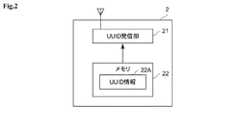
図2は、図1に示すセンサ情報発信機2の機能的構成の一例を示す図である。センサ情報発信機2は、UUID発信部21とメモリ22を有している。なお、センサ情報発信機2は、省電力化を図るために送信機能のみを有する構成となっているが、省電力であれば他の機能(受信機能)を備える装置であってもよい。UUID発信部21は、たとえば、Bluetooth(登録商標)などのアンテナおよびICチップを内蔵した無線通信モジュールである。メモリ22にはUUID情報22Aが格納されている。UUID情報22Aは、上述したUUID情報の一例であり、このセンサ情報発信機2を識別するための識別子、あるいはセンサネットワークシステムを識別するための識別子である。 FIG. 2 is a diagram showing an example of the functional configuration of thesensor information transmitter 2 shown in FIG. Thesensor information transmitter 2 has aUUID transmitter 21 and amemory 22. Thesensor information transmitter 2 is configured to have only a transmission function in order to save power, but may be a device having another function (reception function) as long as it saves power. TheUUID transmission unit 21 is, for example, a wireless communication module incorporating an antenna such as Bluetooth (registered trademark) and an IC chip. TheUUID information 22A is stored in thememory 22. TheUUID information 22A is an example of the above-mentioned UUID information, and is an identifier for identifying thesensor information transmitter 2 or an identifier for identifying the sensor network system.

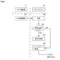
図3は、図1に示すスマートフォン3の機能的構成の一例を示す図である。スマートフォン3は、センサ情報受信部31と、データセット生成処理部32と、位置情報取得部33と、データセット送信部34と、メモリ35とを有している。 FIG. 3 is a diagram showing an example of the functional configuration of thesmartphone 3 shown in FIG. Thesmartphone 3 has a sensorinformation receiving unit 31, a data setgeneration processing unit 32, a positioninformation acquisition unit 33, a dataset transmission unit 34, and amemory 35.

センサ情報受信部31は、センサ情報発信機2側の通信インタフェースと互換性のある通信インタフェースであり、たとえば、Bluetooth(登録商標)などのアンテナおよびICチップを内蔵した無線通信モジュールである。 The sensorinformation receiving unit 31 is a communication interface compatible with the communication interface on thesensor information transmitter 2 side, and is, for example, a wireless communication module incorporating an antenna such as Bluetooth (registered trademark) and an IC chip.

データセット生成処理部32は、センサ情報受信部31を介してセンサ情報発信機2から発信されるUUID情報22Aを受信すると、後述するサービスサーバ4にて必要となるデータセットの作成処理を開始する。このデータセット生成処理部32により生成されるデータセットに含まれる情報は、たとえば、センサ情報発信機2から受信したUUID情報22A、後述の位置情報取得部33にて取得する位置情報、電波強度などから推測されるスマートフォン3とセンサ情報発信機2との距離情報、センサ情報発信機2からUUID情報22Aを受信した時刻情報などである。なお、データセットに含まれる情報は、これらの情報に限らず、サービスサーバ4側で必要となる情報に応じて適宜変更することが可能である。 When the data setgeneration processing unit 32 receives theUUID information 22A transmitted from thesensor information transmitter 2 via the sensorinformation receiving unit 31, the data setgeneration processing unit 32 starts the data set creation process required by theservice server 4 described later. .. The information included in the data set generated by the data setgeneration processing unit 32 includes, for example,UUID information 22A received from thesensor information transmitter 2, position information acquired by the positioninformation acquisition unit 33 described later, radio wave intensity, and the like. The distance information between thesmartphone 3 and thesensor information transmitter 2 inferred from the above, the time information when theUUID information 22A is received from thesensor information transmitter 2, and the like. The information included in the data set is not limited to these information, and can be appropriately changed according to the information required on theservice server 4 side.

位置情報取得部33は、スマートフォン3の位置情報を取得する。位置情報は、スマートフォン3のGPS機能により得られた位置情報やジャイロセンサなどを用いて得られた方向情報、方角情報などを取得すればよい。なお、スマートフォン3のユーザU2やユーザU3が屋内や地下に位置しており、GPSによる位置特定がうまく機能しない場合には直近の位置情報を利用するようにしてもよい。 The positioninformation acquisition unit 33 acquires the position information of thesmartphone 3. As the position information, the position information obtained by the GPS function of thesmartphone 3, the direction information obtained by using the gyro sensor, the direction information, and the like may be acquired. If the user U2 or the user U3 of thesmartphone 3 is located indoors or underground and the position identification by GPS does not work well, the latest position information may be used.

データセット送信部34は、請求項の管理外センサ情報送信部の一例であり、データセット生成処理部32により生成されたデータセットをサービスサーバ4へ送信する。データセット送信部34は、仮にセンサ情報発信機2から受信したUUID情報22Aが自己の管理対象外のUUID情報(管理外センサ情報)であったとしてもサービスサーバ4へ送信することができる。 The dataset transmission unit 34 is an example of the unmanaged sensor information transmission unit according to the claim, and transmits the data set generated by the data setgeneration processing unit 32 to theservice server 4. Even if theUUID information 22A received from thesensor information transmitter 2 is UUID information (unmanaged sensor information) that is not subject to its own management, the dataset transmission unit 34 can transmit the UUID information to theservice server 4.

メモリ35には、管理対象となるUUID情報35Aと、アプリケーションプログラム35Bとが少なくとも記憶されている。UUID情報35Aは、センサ情報発信機2から受信したUUID情報22Aが自己の管理対象となっているセンサ情報であるか否かを判断するための情報である。アプリケーションプログラム35Bは、本システムにおいてスマートフォン3が実行する各種処理を行うためのプログラムである。なお、メモリ35にデータセット生成処理部32が生成したデータセットを一時的に記録、または蓄積して記録するようにしてもよい。 At least theUUID information 35A to be managed and theapplication program 35B are stored in thememory 35. TheUUID information 35A is information for determining whether or not theUUID information 22A received from thesensor information transmitter 2 is the sensor information managed by itself. Theapplication program 35B is a program for performing various processes executed by thesmartphone 3 in this system. The data set generated by the data setgeneration processing unit 32 may be temporarily recorded or accumulated and recorded in thememory 35.

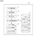
図4は、図1に示すサービスサーバ4の機能的構成の一例を示す図である。サービスサーバ4は、センサ情報受信部41と、センサ情報比較部42と、メモリ43と、サービス実行処理部44と、送信処理部45とを有している。 FIG. 4 is a diagram showing an example of the functional configuration of theservice server 4 shown in FIG. Theservice server 4 has a sensorinformation receiving unit 41, a sensorinformation comparing unit 42, amemory 43, a serviceexecution processing unit 44, and atransmission processing unit 45.

センサ情報受信部41は、ネットワークA1を介して、スマートフォン3のデータセット送信部34が送信したデータセットを受信する。 The sensorinformation receiving unit 41 receives the data set transmitted by the dataset transmitting unit 34 of thesmartphone 3 via the network A1.

センサ情報比較部42は、請求項の第2のサーバの判定部の一例であり、センサ情報受信部41にて受信したデータセットに含まれるUUID情報22Aと、後述するメモリ43に記憶されているUUID情報43Aとを比較する。センサ情報比較部42の比較結果は、サービス実行処理部44へと供給される。 The sensorinformation comparison unit 42 is an example of the determination unit of the second server of the claim, and is stored in theUUID information 22A included in the data set received by the sensorinformation reception unit 41 and thememory 43 described later. Compare withUUID information 43A. The comparison result of the sensorinformation comparison unit 42 is supplied to the serviceexecution processing unit 44.

メモリ43は、サービスサーバ4において管理対象となるUUID情報43Aと、アプリケーションプログラム43Bとが少なくとも記憶されている。UUID情報43Aは、サービスサーバ4が提供するサービスに対応したUUID情報である。アプリケーションプログラム43Bは、サービスサーバ4が実行する各種処理を行うためのプログラムである。なお、メモリ43に、スマートフォン3から送信されてきたデータセットを一時的に記録、または蓄積して記録するようにしてもよい。 Thememory 43 stores at least theUUID information 43A to be managed by theservice server 4 and theapplication program 43B. TheUUID information 43A is the UUID information corresponding to the service provided by theservice server 4. Theapplication program 43B is a program for performing various processes executed by theservice server 4. The data set transmitted from thesmartphone 3 may be temporarily recorded or accumulated and recorded in thememory 43.

サービス実行処理部44は、センサ情報比較部42の比較結果に応じて、所定の処理を実行する。ここでいう所定の処理とは、たとえば、サービス実行処理部44は、センサ情報比較部42の比較によりUUID情報が同じ場合には、そのUUID情報を含むデータセットから判明する位置情報などを利用者端末6に対して送信する処理を実行する。一方、サービス実行処理部44は、センサ情報比較部42の比較によりUUID情報が異なる場合には、後述する管理サーバ5へ、その異なるUUID情報の転送処理を実行する。 The serviceexecution processing unit 44 executes a predetermined process according to the comparison result of the sensorinformation comparison unit 42. The predetermined processing referred to here is, for example, that the serviceexecution processing unit 44 uses the position information or the like found from the data set including the UUID information when the UUID information is the same by the comparison of the sensorinformation comparison unit 42. The process of transmitting to the terminal 6 is executed. On the other hand, when the UUID information is different due to the comparison of the sensorinformation comparison unit 42, the serviceexecution processing unit 44 executes the transfer processing of the different UUID information to themanagement server 5 described later.

送信処理部45は、請求項の第1のサーバの管理外センサ情報送信部、第2のサーバの送信部の一例であり、サービス実行処理部44の処理に基づいて、UUID情報22Aを含むデータセットから判明する位置情報、または、UUID情報22Aの送信を実行する。 Thetransmission processing unit 45 is an example of an unmanaged sensor information transmission unit of the first server in the claim and a transmission unit of the second server, and is data includingUUID information 22A based on the processing of the serviceexecution processing unit 44. The position information found from the set or theUUID information 22A is transmitted.

図5は、図1に示す管理サーバ5の機能的構成の一例を示す図である。管理サーバ5は、請求項の管理サーバの一例である。管理サーバ5は、センサ情報受信部51と、転送先検索部52と、メモリ53と、問い合わせ部54と、センサ情報中継処理部55とを有している。 FIG. 5 is a diagram showing an example of the functional configuration of themanagement server 5 shown in FIG. Themanagement server 5 is an example of the management server of the claims. Themanagement server 5 has a sensorinformation receiving unit 51, a transferdestination search unit 52, amemory 53, aninquiry unit 54, and a sensor informationrelay processing unit 55.

センサ情報受信部51は、ネットワークA3を介して送信処理部45が送信したUUID情報22Aを含むデータセットを受信する。 The sensorinformation receiving unit 51 receives a data set including theUUID information 22A transmitted by thetransmission processing unit 45 via the network A3.

転送先検索部52は、センサ情報受信部51が受信したUUID情報22Aに基づいて後述のメモリ53に記録された管理テーブル53Aを参照して転送先となるサービスサーバを検索する。 The transferdestination search unit 52 searches for a service server to be a transfer destination by referring to the management table 53A recorded in thememory 53 described later based on theUUID information 22A received by the sensorinformation receiving unit 51.

メモリ53は、管理テーブル53Aと、ログデータ53Bと、アプリケーションプログラム53Cとが少なくとも記憶されている。 Thememory 53 stores at least the management table 53A, thelog data 53B, and theapplication program 53C.

管理テーブル53Aは、請求項の管理テーブルの一例であり、複数のUUID情報(センサ情報)とサービスサーバに関する情報との組み合わせを複数記憶しているテーブルである。図6は、図5に示す管理テーブル53Aに記録されているデータの一例を示す図である。たとえば、図6に示すように、管理テーブル53Aには、各センサネットワークシステムを一意に識別するためのID,センサネットワーク名、UUID情報、UUID情報を管理しているサービスサーバ4を特定するための情報であるIPアドレス情報などが関連付けて記録されている。なお、UUID情報を管理しているサービスサーバ4を特定することができるのであれば、IPアドレス情報以外の情報(たとえばサービスサーバ4のURLなど)であってもよい。 The management table 53A is an example of a management table for claims, and is a table that stores a plurality of combinations of a plurality of UUID information (sensor information) and information regarding a service server. FIG. 6 is a diagram showing an example of data recorded in the management table 53A shown in FIG. For example, as shown in FIG. 6, in the management table 53A, an ID for uniquely identifying each sensor network system, a sensor network name, UUID information, and aservice server 4 that manages UUID information are specified. IP address information, which is information, is recorded in association with each other. If theservice server 4 that manages the UUID information can be specified, the information may be information other than the IP address information (for example, the URL of the service server 4).

ログデータ53Bは、サービスサーバ4から転送されてきたUUID情報22Aを含むデータセットの履歴を示す情報である。アプリケーションプログラム53Cは、管理サーバ5が実行する各種処理を行うためのプログラムである。 Thelog data 53B is information indicating the history of the data set including theUUID information 22A transferred from theservice server 4. Theapplication program 53C is a program for performing various processes executed by themanagement server 5.

問い合わせ部54は、請求項の転送要否問い合わせ部の一例であり、転送先検索部52にて検索されたサービスサーバ4に対してUUID情報22Aの要否を問い合わせる。 Theinquiry unit 54 is an example of the transfer necessity inquiry unit of the claim, and inquires about the necessity of theUUID information 22A to theservice server 4 searched by the transferdestination search unit 52.

センサ情報中継処理部55は、請求項のセンサ情報中継部の一例であり、問い合わせ部54から転送要否を問い合わせたサービスサーバ4BからUUID情報22Aの送信要求を受信した場合に、そのUUID情報22Aを含むデータセットを送信する。 The sensor informationrelay processing unit 55 is an example of the sensor information relay unit according to the claim, and when theservice server 4B inquiring about the necessity of forwarding from theinquiry unit 54 receives the transmission request of theUUID information 22A, theUUID information 22A Send a dataset containing.

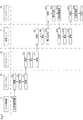
図7は、図1に示すセンサ情報発信機2、スマートフォン3A,サービスサーバ4A,管理サーバ5,サービスサーバ4Bが各々で実行される処理のフローチャートを示す図である。 FIG. 7 is a diagram showing a flowchart of processing executed by each of thesensor information transmitter 2, thesmartphone 3A, theservice server 4A, themanagement server 5, and theservice server 4B shown in FIG.

センサ情報発信機2がUUID情報22Aを発信し(ステップS1)、スマートフォン3AがUUID情報22Aを受信する(ステップS2)。すると、スマートフォン3AがUUID情報22Aについて管理対象のUUID情報35Aと同一であるか否かを判定し(ステップS3)、管理対象のUUID情報35Aと同一でないときはスマートフォン3Aが、そのUUID情報22Aを含むデータセットをサービスサーバ4Aへ転送する(ステップS4)。その後、サービスサーバ4AがUUID情報22Aを含むデータセットを受信する(ステップS5)と、その受信したデータセットに含まれるUUID情報22Aが自己のサービスを提供する対象となるUUID情報35Aと同一であるか否かを判定する(ステップS6)。サービスサーバ4Aは、自己のサービスを提供する対象ではない場合、そのUUID情報22Aを含むデータセットは管理サーバ5へと転送される(ステップS7)。管理サーバ5では、UUID情報22Aを含むデータセットを受信すると(ステップS8)、UUID情報22Aの宛先となるサーバの検索を実行する(ステップS9)。管理サーバ5は、宛先となるサーバが特定されると、そのサーバに対してUUID情報22Aの要否を問い合わせる(ステップS10)。なお、ここではUUID情報22Aからサービスサーバ4Aが宛先であると判明したものとする。サービスサーバ4Bは、管理サーバ5から要否の問い合わせを受信すると(ステップS11)、その要否の問い合わせに対してUUID情報22Aの要否を判定する(ステップS12)。サービスサーバ4Bは、その判定結果を管理サーバ5へ送信する(ステップS13)。管理サーバ5が、サービスサーバ4Bから送信されてきた判定結果を受信すると(ステップS14)、UUID情報22Aの要否の判定し(ステップS15)、その要否判定の結果、送信が必要である場合には、UUID情報22Aを含むデータセットを送信する(ステップS16)。サービスサーバ4Bは、管理サーバ5から送信されたUUID情報22Aを含むデータセットを受信し(ステップS17)、自己のサービスにそのUUID情報22Aを含むデータセットを利用して所定の処理を実行する(END)。以下、これらの処理の詳細について説明を更に行う。 Thesensor information transmitter 2 transmits theUUID information 22A (step S1), and thesmartphone 3A receives theUUID information 22A (step S2). Then, it is determined whether or not thesmartphone 3A is the same as theUUID information 35A to be managed with respect to theUUID information 22A (step S3), and if it is not the same as theUUID information 35A to be managed, thesmartphone 3A uses theUUID information 22A. The including data set is transferred to theservice server 4A (step S4). After that, when theservice server 4A receives the data set including theUUID information 22A (step S5), theUUID information 22A included in the received data set is the same as theUUID information 35A to which the service is provided. Whether or not it is determined (step S6). When theservice server 4A is not the target for providing its own service, the data set including theUUID information 22A is transferred to the management server 5 (step S7). When themanagement server 5 receives the data set including theUUID information 22A (step S8), themanagement server 5 searches for the server that is the destination of theUUID information 22A (step S9). When the destination server is specified, themanagement server 5 inquires of the server whether or not theUUID information 22A is necessary (step S10). Here, it is assumed that theservice server 4A is found to be the destination from theUUID information 22A. When theservice server 4B receives the necessity inquiry from the management server 5 (step S11), theservice server 4B determines the necessity of theUUID information 22A in response to the necessity inquiry (step S12). Theservice server 4B transmits the determination result to the management server 5 (step S13). When themanagement server 5 receives the determination result transmitted from theservice server 4B (step S14), it determines the necessity of theUUID information 22A (step S15), and as a result of the necessity determination, transmission is necessary. Transmits a data set containingUUID information 22A (step S16). Theservice server 4B receives the data set including theUUID information 22A transmitted from the management server 5 (step S17), and executes a predetermined process by using the data set including theUUID information 22A for its own service (step S17). END). The details of these processes will be further described below.

図8は、図7のステップS1〜S4に示すセンサ情報発信機2とスマートフォン3Aとの間の詳細な処理を示したフローチャートである。センサ情報発信機2は、UUID情報22Aを発信する(ステップS21)。スマートフォン3Aは、センサ情報発信機2と所定の範囲内に接近すると、UUID情報22Aを受信する(ステップS22)。スマートフォン3Aは、ステップS22で受信したUUID情報22Aが管理対象のUUID情報35Aと同一であるか否かを判定する(ステップS23)。スマートフォン3Aは、管理対象のUUID情報35Aと同一であると判定した場合には所定の処理を実行する(ステップS24)。なお、ここでいう所定の処理とはたとえば、サービスサーバ4Aに対して、このUUID情報22Aを含むデータセットを生成して、利用者端末6Aへ送信するなどである。スマートフォン3Aは、管理対象のUUID情報35Aと同一ではない場合(ステップS23でNO)、サービスサーバ4AへそのUUID情報22Aと、管理対象外であることを識別できるタグを含むデータセットを転送する(ステップS25)。 FIG. 8 is a flowchart showing detailed processing between thesensor information transmitter 2 and thesmartphone 3A shown in steps S1 to S4 of FIG. 7. Thesensor information transmitter 2 transmitsUUID information 22A (step S21). When thesmartphone 3A approaches thesensor information transmitter 2 within a predetermined range, thesmartphone 3A receives theUUID information 22A (step S22). Thesmartphone 3A determines whether or not theUUID information 22A received in step S22 is the same as theUUID information 35A to be managed (step S23). When thesmartphone 3A determines that theUUID information 35A to be managed is the same, thesmartphone 3A executes a predetermined process (step S24). The predetermined processing referred to here is, for example, generating a data set including theUUID information 22A for theservice server 4A and transmitting it to theuser terminal 6A. When thesmartphone 3A is not the same as theUUID information 35A to be managed (NO in step S23), thesmartphone 3A transfers theUUID information 22A to theservice server 4A and a data set including a tag that can identify that the UUID information is not managed (NO). Step S25).

図9は、図7のステップS4〜S7に示すスマートフォン3Aとサービスサーバ4Aとの間の詳細な処理を示したフローチャートである。ステップS25にてスマートフォン3Aがサービスサーバ4AにUUID情報22Aを含むデータセットを転送すると、サービスサーバ4Aは、それを受信し(ステップS26)、管理対象のUUID情報35Aと同一であるか否かを判定する(ステップS27)。なお、図8のステップS23の判定結果をそのまま活用して、サービスサーバ4A側で判定しなくてもよい。管理対象のUUID情報35Aと同一である場合には、サービスサーバ4Aは、所定の処理を実行する(ステップS28)。一方、サービスサーバ4Aは、管理対象のUUID情報35Aと同一ではない場合には管理サーバ5へUUID情報22Aを含むデータセットの転送を行う(ステップS29)。 FIG. 9 is a flowchart showing detailed processing between thesmartphone 3A and theservice server 4A shown in steps S4 to S7 of FIG. 7. When thesmartphone 3A transfers the data set including theUUID information 22A to theservice server 4A in step S25, theservice server 4A receives it (step S26) and determines whether or not it is the same as theUUID information 35A to be managed. Determine (step S27). It is not necessary to utilize the determination result in step S23 of FIG. 8 as it is and make a determination on theservice server 4A side. If it is the same as theUUID information 35A to be managed, theservice server 4A executes a predetermined process (step S28). On the other hand, if theservice server 4A is not the same as theUUID information 35A to be managed, theservice server 4A transfers the data set including theUUID information 22A to the management server 5 (step S29).

図10は、図7のステップS7〜S10に示すサービスサーバ4Aと管理サーバ5と間の詳細な処理を示したフローチャートである。サービスサーバ4Aが管理サーバ5へUUID情報22Aを含むデータセットの転送を行うと(ステップS29)、管理サーバ5がそれを受信し(ステップS30)、転送先となるサービスサーバの検索処理を実行する(ステップS31)。そして、検索の結果、UUID情報22Aの管理はサービスサーバ4Bであることが判明すると、サービスサーバ4Bに対してUUID情報22Aを含むデータセットの要否について問い合わせ処理を実行する(ステップS32)。 FIG. 10 is a flowchart showing detailed processing between theservice server 4A and themanagement server 5 shown in steps S7 to S10 of FIG. 7. When theservice server 4A transfers the data set including theUUID information 22A to the management server 5 (step S29), themanagement server 5 receives it (step S30) and executes a search process for the service server to be the transfer destination. (Step S31). Then, as a result of the search, when it is found that the management of theUUID information 22A is theservice server 4B, theservice server 4B is inquired about the necessity of the data set including theUUID information 22A (step S32).

図11は、図7のステップS10〜S13に示す管理サーバ5とサービスサーバ4Bとの間の詳細な処理を示したフローチャートである。管理サーバ5が、UUID情報22Aの要否についてサービスサーバ4Bへ問い合わせ処理を実行すると(ステップS32)、サービスサーバ4Bは、UUID情報22Aの要否の問い合わせを受信し(ステップS33)、問い合わせのあったUUID情報22Aについての要否を判定する。なお、ここでのサービスサーバ4Bの要否としては、たとえば、自己の管理対象となるUUID情報である場合には、常に受信するという判定基準を有していてもよいし、要否は個別に判断するという判定基準として、サービスサーバ4Bの管理者、運営者、あるいは利用者が設定した独自のルール設定に基づいて決定するようにしてもよい。 FIG. 11 is a flowchart showing detailed processing between themanagement server 5 and theservice server 4B shown in steps S10 to S13 of FIG. 7. When themanagement server 5 executes an inquiry process to theservice server 4B regarding the necessity of theUUID information 22A (step S32), theservice server 4B receives the inquiry as to whether theUUID information 22A is necessary (step S33), and the inquiry is made. It is determined whether or not theUUID information 22A is necessary. As for the necessity of theservice server 4B here, for example, in the case of UUID information to be managed by itself, it may have a determination criterion that it is always received, and the necessity is individually determined. As a determination criterion for determination, the determination may be made based on the original rule setting set by the administrator, the operator, or the user of theservice server 4B.

(第2実施形態)
続いて、本発明の第2実施形態に係るセンサネットワークシステムについて説明する。図12は、本発明の第2実施形態に係るセンサネットワーク中継システムにおける管理サーバ5Aの機能的構成の一例を示す図である。なお、管理サーバ5A以外の構成は、図1に示した第1実施形態に係るセンサネットワーク中継システム1Aと同一であるため、各装置の機能および図示を省略する。管理サーバ5Aは、たとえば、サービスサーバ4Aからサービスサーバ4BへUUID情報22Aを転送した場合、転送先のサービスサーバ4Bへ独自のポイントを課金したり、転送元のサービスサーバ4Aに独自のポイントを付与したりすることができるように構成されている。
(Second Embodiment)
Subsequently, the sensor network system according to the second embodiment of the present invention will be described. FIG. 12 is a diagram showing an example of a functional configuration of themanagement server 5A in the sensor network relay system according to the second embodiment of the present invention. Since the configurations other than themanagement server 5A are the same as those of the sensor network relay system 1A according to the first embodiment shown in FIG. 1, the functions and illustrations of the respective devices are omitted. For example, when themanagement server 5A transfersUUID information 22A from theservice server 4A to theservice server 4B, themanagement server 5A charges a unique point to the transferdestination service server 4B or grants a unique point to the transfersource service server 4A. It is configured so that it can be used.

図12に示す管理サーバ5Aは、センサ情報受信部51と、転送先検索部52と、メモリ53と、問い合わせ部54と、センサ情報中継処理部55と、ポイント管理部56とを有している。なお、センサ情報受信部51と、転送先検索部52と、問い合わせ部54と、センサ情報中継処理部55とは図5で説明した管理サーバ5と同様の機能であるため、同一の符号を用いることとし、これらの説明を省略する。 Themanagement server 5A shown in FIG. 12 includes a sensorinformation receiving unit 51, a transferdestination search unit 52, amemory 53, aninquiry unit 54, a sensor informationrelay processing unit 55, and apoint management unit 56. .. Since the sensorinformation receiving unit 51, the transferdestination search unit 52, theinquiry unit 54, and the sensor informationrelay processing unit 55 have the same functions as themanagement server 5 described with reference to FIG. 5, the same reference numerals are used. However, these explanations will be omitted.

ポイント管理部56は、ポイント課金部56Aと、ポイント付与部56Bとを有している。ポイント課金部56Aは、サービスサーバ4BがUUID情報22Aの送信要求を受信した場合、サービスサーバ4Bに対して所定のポイントを課金する。ポイント付与部56Bは、ポイント課金部56Aによりサービスサーバ4Bに課金されたポイントに応じて、サービスサーバ4Aに対して所定のポイントを付与する。 Thepoint management unit 56 has apoint charging unit 56A and apoint giving unit 56B. When theservice server 4B receives the transmission request of theUUID information 22A, thepoint charging unit 56A charges theservice server 4B for a predetermined point. Thepoint giving unit 56B gives a predetermined point to theservice server 4A according to the points charged to theservice server 4B by thepoint charging unit 56A.

なお、本実施形態におけるサービスサーバ4Bは、図4で説明した構成と同一であるが、センサ情報受信部41が、請求項の問い合わせ受付部として機能し、センサ情報比較部42が、請求項の要否判定部として機能する。 Theservice server 4B in the present embodiment has the same configuration as that described with reference to FIG. 4, but the sensorinformation receiving unit 41 functions as an inquiry receiving unit according to the claim, and the sensorinformation comparing unit 42 functions as an inquiry receiving unit according to the claim. It functions as a necessity judgment unit.

図13は、図12に示す管理サーバ5Aとサービスサーバ4Bとの間の処理を示すフローチャートである。管理サーバ5Aは、UUID情報22Aの要否をサービスサーバ4Bに問い合わせる(ステップS32)。サービスサーバ4Bは、管理サーバ5AからUUID情報22Aの要否の問い合わせを受信すると(ステップS33)、受信要否の判定を行う(ステップS34)。そして、サービスサーバ4Bは、ステップS34の判定結果を管理サーバ5Aへと送信する(ステップS35)。管理サーバ5Bは、判定結果を受信すると(ステップS36)、サービスサーバ4BのUUID情報22Aの要否について判定し(ステップS37)、必要であると判定した場合には、UUID情報22Aを含むデータセットを送信し(ステップS38)、不要である場合には、処理を終了する(END)。一方、サービスサーバ4Bは、ステップS38で送信されてきたUUID情報22Aを受信すると(ステップS39)、UUID情報22Aに応じた所定の処理を実行し(ステップS40)、処理を終了する。なお、ここでの所定の処理とは、たとえば、UUID情報22Aを含むデータセットから判明する位置情報などを利用者端末6に対して送信する処理などである。 FIG. 13 is a flowchart showing processing between themanagement server 5A and theservice server 4B shown in FIG. Themanagement server 5A inquires theservice server 4B about the necessity of theUUID information 22A (step S32). When theservice server 4B receives an inquiry as to whether or not theUUID information 22A is necessary from themanagement server 5A (step S33), theservice server 4B determines whether or not the reception is necessary (step S34). Then, theservice server 4B transmits the determination result of step S34 to themanagement server 5A (step S35). When the management server 5B receives the determination result (step S36), it determines whether or not theUUID information 22A of theservice server 4B is necessary (step S37), and if it determines that it is necessary, the data set including theUUID information 22A. Is transmitted (step S38), and if it is unnecessary, the process ends (END). On the other hand, when theservice server 4B receives theUUID information 22A transmitted in step S38 (step S39), theservice server 4B executes a predetermined process according to theUUID information 22A (step S40), and ends the process. The predetermined process here is, for example, a process of transmitting location information or the like found from a data set includingUUID information 22A to the user terminal 6.

なお、図13の例では、UUID情報22Aの転送処理毎にポイント課金とポイント付与を行うようにしているが、たとえば一定期間に両者の間で転送したUUID情報22Aの差分により、サービスサーバ4Aとサービスサーバ4Bとの間でポイント課金の調整を行ってから処理するようにしてもよい。 In the example of FIG. 13, points are charged and points are given for each transfer process of theUUID information 22A. For example, due to the difference between theUUID information 22A transferred between the two in a certain period, theservice server 4A and theservice server 4A are assigned. The point billing may be adjusted with theservice server 4B before processing.

以上で説明したように、第1実施形態のセンサネットワーク中継システム1Aおよび第2実施形態のセンサネットワーク中継システムでは、UUID情報22A(センサ情報)を外部へ発信するセンサ情報発信機2、センサ情報発信機2から発信されたUUID情報22Aを受信して自己の管理対象となるUUID情報35Aと同一のセンサ情報である場合には、予め送信先として設定されたサービスサーバ4A(第1のサーバ)へUUID情報35Aを送信するスマートフォン3A(センサ情報送受信機)とを有するシステムであって、スマートフォン3Aは、UUID情報22Aが自己の管理対象外のセンサ情報の場合であっても、サービスサーバ4AへUUID情報22Aを送信するデータセット送信部34(管理外センサ情報送信部)を有し、サービスサーバ4Aは、複数のセンサ情報の転送先を管理する管理サーバ5へUUID情報22Aを転送する送信処理部45(管理外センサ情報転送部)を有し、管理サーバ5,5Aは、複数のセンサ情報と、サーバ情報との組み合わせを複数記憶している管理テーブル53Aと、管理テーブル53Aを参照して、サービスサーバ4Aから転送されてきたUUID情報22A(管理外センサ情報)から、転送すべきサービスサーバ4B(第2のサーバ)を検索する転送先検索部52と、転送先検索部52により検索されたサービスサーバ4Bに対して、UUID情報22Aの要否を問い合わせる問い合わせ部54(転送要否問い合わせ部)と、問い合わせ部54の問い合わせの結果として、サービスサーバ4BからUUID情報22Aの送信要求を受信した場合には、UUID情報22Aをサービスサーバ4Bへ送信するセンサ情報中継処理部55とを有し、サービスサーバ4Bは、管理サーバ5,5Aからの問い合わせ要求を受信した場合に、UUID情報22Aを含む信号の受信要否を判定するセンサ情報比較部42(判定部)と、センサ情報比較部42の比較結果により受信することが必要である場合には、受信要求を管理サーバ5,5Aに対して送信する送信処理部45(送信部)とを有するので、UUIDが異なるセンサネットワークサービス間であってもUUID情報のやり取りが可能になるため、管理対象外のセンサ情報が検出された場合であっても、必要とされるサービスサーバへと適切に送信されて処理することができるようになる。 As described above, in the sensor network relay system 1A of the first embodiment and the sensor network relay system of the second embodiment, thesensor information transmitter 2 for transmittingUUID information 22A (sensor information) to the outside, and the sensor information transmission When theUUID information 22A transmitted from themachine 2 is received and the sensor information is the same as theUUID information 35A to be managed by itself, the sensor information is sent to theservice server 4A (first server) set in advance as the transmission destination. It is a system having asmartphone 3A (sensor information transmitter / receiver) that transmitsUUID information 35A, and thesmartphone 3A UUID to theservice server 4A even when theUUID information 22A is sensor information that is not subject to its own management. A transmission processing unit that has a dataset transmission unit 34 (unmanaged sensor information transmission unit) that transmitsinformation 22A, and theservice server 4A transfersUUID information 22A to amanagement server 5 that manages transfer destinations of a plurality of sensor information. The management server 5.5A has 45 (unmanaged sensor information transfer unit), and refers to the management table 53A and the management table 53A that store a plurality of combinations of the plurality of sensor information and the server information. From theUUID information 22A (unmanaged sensor information) transferred from theservice server 4A, the transferdestination search unit 52 for searching theservice server 4B (second server) to be transferred and the transferdestination search unit 52 searched. When a transmission request forUUID information 22A is received from theservice server 4B as a result of an inquiry from the inquiry unit 54 (transfer necessity inquiry unit) that inquires theservice server 4B about the necessity of theUUID information 22A and theinquiry unit 54. Has a sensor informationrelay processing unit 55 that transmitsUUID information 22A to theservice server 4B, and theservice server 4B receives a signal including theUUID information 22A when receiving an inquiry request from themanagement servers 5 and 5A. When it is necessary to receive the sensor information comparison unit 42 (judgment unit) that determines the necessity of reception and the comparison result of the sensorinformation comparison unit 42, the reception request is transmitted to themanagement servers 5 and 5A. Since it has a transmission processing unit 45 (transmission unit) to perform UUID information, UUID information can be exchanged even between sensor network services having different UUIDs, so that even when sensor information not subject to management is detected. , Will be properly sent to the required service server for processing.

また、第2実施形態のセンサネットワーク中継システムにおける管理サーバ5Aでは、サービスサーバ4Bよりセンサ情報を含む信号の送信要求があった場合に、サービスサーバ4Bに対して所定のポイントを課金するポイント課金部56Aと、ポイント課金部56Aにより課金されたポイントに応じて、サービスサーバ4Aに対して所定のポイントを付与するポイント付与部56Bとを有しているので、これにより、各センサネットワークシステムでの他のセンサネットワークシステムへの貢献度に応じて課金ポイントの調整を行うことが可能であり、獲得したポイントをそのネットワーク内の電子通貨のような役割として各センサネットワークシステムに提供できる。その結果、サービス提供地域の更なる拡大、センサネットワークシステムへの設備投資の資金としても活用することができ、規模を更に広げることが可能となる。 Further, in themanagement server 5A in the sensor network relay system of the second embodiment, when a signal transmission request including sensor information is received from theservice server 4B, a point charging unit that charges a predetermined point to theservice server 4B. Since it has 56A and apoint giving unit 56B that gives a predetermined point to theservice server 4A according to the points charged by thepoint charging unit 56A, the other in each sensor network system. It is possible to adjust the billing points according to the degree of contribution to the sensor network system, and the acquired points can be provided to each sensor network system as a role like an electronic currency in the network. As a result, it can be used as a fund for further expansion of the service providing area and capital investment in the sensor network system, and the scale can be further expanded.

また、所定のサービスを提供するサービスサーバ4A(第1のサーバ)と、サービスサーバ4Aとは提供するサービスが異なる、もしくはサーバの運営事業者が異なるサービスサーバ4B(第2のサーバ)とのいずれとも通信可能な管理サーバ5(情報処理装置)であって、サービスサーバ4A側から送信されてきたセンサ情報を受信するセンサ情報受信部51と、センサ情報と、そのセンサ情報を管理するサービスサーバ4のIPアドレス情報(サービスサーバ4を特定する情報)とが関連付けて記憶されている管理テーブル53Aと、管理テーブル53Aを参照してサービスサーバに対して、センサ情報の要否を問い合わせる問い合わせ部54と、問い合わせ部54の問い合わせの結果として、サービスサーバ4からセンサ情報の送信要求があった場合に、そのセンサ情報をサービスサーバ4へ送信するセンサ情報中継処理部55(送信部)とを有するので、管理対象外のセンサ情報が検出された場合であっても、必要とされるサービスサーバ4へと管理サーバ5により適切に送信されて処理することができる。 In addition, either theservice server 4A (first server) that provides a predetermined service and theservice server 4B (second server) that the service provided by theservice server 4A is different or the server operator is different. A management server 5 (information processing device) capable of communicating with each other, a sensorinformation receiving unit 51 that receives sensor information transmitted from theservice server 4A side, and aservice server 4 that manages the sensor information and the sensor information. The management table 53A, which is stored in association with the IP address information (information that identifies the service server 4), and theinquiry unit 54, which inquires the service server about the necessity of sensor information by referring to the management table 53A. As a result of the inquiry of theinquiry unit 54, when theservice server 4 requests transmission of sensor information, theservice server 4 has a sensor information relay processing unit 55 (transmission unit) that transmits the sensor information to theservice server 4. Even when sensor information that is not managed can be detected, it can be appropriately transmitted by themanagement server 5 to the requiredservice server 4 and processed.

また、管理サーバ5Aは、サービスサーバ4BがUUID情報22Aの送信要求を受信した場合、サービスサーバ4Bに対して所定のポイントを課金するポイント課金部56Aと、ポイント課金部56Aにより課金されたポイントに応じて、サービスサーバ4Aに対して所定のポイントを付与するポイント付与部56Bとを有しているので、これにより、各センサネットワークシステムでの他のセンサネットワークシステムへの貢献度に応じて課金ポイントの調整を行うことが可能であり、獲得したポイントをそのネットワーク内の電子通貨のような役割として各センサネットワークシステムに提供できる。その結果、サービス提供地域の更なる拡大、センサネットワークシステムへの設備投資の資金としても活用することができ、規模を更に広げることが可能となる。 Further, when theservice server 4B receives the transmission request of theUUID information 22A, themanagement server 5A uses thepoint charging unit 56A for charging theservice server 4B for predetermined points and the points charged by thepoint charging unit 56A. Correspondingly, it has apoint giving unit 56B that gives a predetermined point to theservice server 4A, so that the charging points are charged according to the degree of contribution of each sensor network system to other sensor network systems. It is possible to make adjustments, and the points earned can be provided to each sensor network system as a role like an electronic currency in the network. As a result, it can be used as a fund for further expansion of the service providing area and capital investment in the sensor network system, and the scale can be further expanded.

なお、上述した管理サーバ5の動作(情報処理方法)においても、管理サーバ5と同様の効果を奏することができる。 The operation (information processing method) of themanagement server 5 described above can also have the same effect as that of themanagement server 5.

また、上述したサービスサーバ4は、センサ情報発信機2から送信されてきたセンサ情報発信機2のUUID情報22A(センサ情報)と、サービスサーバ4自身が提供するサービスを示すUUID情報35Aとを比較するセンサ情報比較部42と、センサ情報比較部42の比較により、同一のセンサ情報である場合には、所定のサービスを提供するための処理を実行するサービス実行処理部44と、センサ情報比較部42の比較により、異なるセンサ情報である場合には、外部にセンサ情報を含む信号を送信する送信処理部45とを有しているので、従来のように自己の管理外のセンサ情報であっても適切に処理できないということがなく、外部へと転送することができるようになる。 Further, the above-mentionedservice server 4 compares theUUID information 22A (sensor information) of thesensor information transmitter 2 transmitted from thesensor information transmitter 2 with theUUID information 35A indicating the service provided by theservice server 4 itself. When the same sensor information is obtained by comparing the sensorinformation comparison unit 42 and the sensorinformation comparison unit 42, the serviceexecution processing unit 44 that executes a process for providing a predetermined service and the sensorinformation comparison unit 42 According to the comparison of 42, when the sensor information is different, since it has atransmission processing unit 45 that transmits a signal including the sensor information to the outside, the sensor information is not under its own control as in the conventional case. Will be able to be transferred to the outside without being unable to process properly.

また、サービスサーバ4Bは、サービスサーバ4AからUUID情報22A(サービスを示すセンサ情報)の要否についての問い合わせ要求を受け付けるセンサ情報受信部41(問い合わせ受付部)と、センサ情報受信部41で受け付けたUUID情報22Aの要否を判定するセンサ情報比較部42(要否判定部)と、センサ情報比較部42の判定に応じてUUID情報22Aの要否を送信する送信処理部45とを有するので、自分のセンサネットワーク以外で検出されたセンサ情報について要否を判断した上で受信することができるようになる。 Further, theservice server 4B receives the inquiry request from theservice server 4A about the necessity of theUUID information 22A (sensor information indicating the service) by the sensor information receiving unit 41 (inquiry receiving unit) and the sensorinformation receiving unit 41. Since it has a sensor information comparison unit 42 (necessity determination unit) that determines the necessity of theUUID information 22A, and atransmission processing unit 45 that transmits the necessity of theUUID information 22A according to the determination of the sensorinformation comparison unit 42. You will be able to receive sensor information detected outside your own sensor network after determining the necessity.

(第3実施形態)
続いて、本発明の第3実施形態に係るセンサネットワーク中継システム1Cについて説明する。図14は、本発明の第3実施形態に係るセンサネットワーク中継システム1Cの構成を示す図である。図15は、図14に示す各装置の機能的構成および各装置間の関係概略を説明するための図である。図16は、スタンプサーバ4Cのメモリ187に記録されているデータベース内の情報の一例を示す図である。
(Third Embodiment)
Subsequently, the sensornetwork relay system 1C according to the third embodiment of the present invention will be described. FIG. 14 is a diagram showing a configuration of a sensornetwork relay system 1C according to a third embodiment of the present invention. FIG. 15 is a diagram for explaining the functional configuration of each device shown in FIG. 14 and the outline of the relationship between the devices. FIG. 16 is a diagram showing an example of information in the database recorded in thememory 187 of thestamp server 4C.

図14に示すセンサネットワーク中継システム1Cは、図1に示したセンサネットワーク中継システム1Aの構成に、複数のスタンプユニット2Bおよびスタンプサーバ4Cが新たに追加された構成となっている。複数のスタンプユニット2Bは、Aサービス用センサネットワークシステムにて提供されるサービス地域またはBサービス用センサネットワークシステムにて提供されるサービス地域の一部の地域と重複する一定の地域の範囲内にそれぞれが設置されている。たとえば、複数のスタンプユニット2Bは、Bサービス用センサネットワークシステムの利用者であるユーザU145が見守る対象であるユーザU141の移動経路の近辺に設置されており、スマートフォン3Cを所持したユーザU142、U143がスタンプユニット2Bの設置場所付近へ移動すると所定のポイントを獲得することができる仕組みとなっている。なお、センサネットワーク中継システム1Cにおけるサービスサーバ4A,4Bおよび管理サーバ5は、センサネットワーク中継システム1Aにおけるサービスサーバ4A,4Bおよび管理サーバ5と同一の役割、機能であるため、同一の符号を付してこれらの説明を省略する。 The sensornetwork relay system 1C shown in FIG. 14 has a configuration in which a plurality ofstamp units 2B and astamp server 4C are newly added to the configuration of the sensor network relay system 1A shown in FIG. Each of the plurality ofstamp units 2B is within a certain area that overlaps with a part of the service area provided by the A service sensor network system or the service area provided by the B service sensor network system. Is installed. For example, the plurality ofstamp units 2B are installed in the vicinity of the movement path of the user U141, which is the target to be watched by the user U145 who is the user of the sensor network system for the B service, and the users U142 and U143 who have thesmartphone 3C When thestamp unit 2B is moved to the vicinity of the installation location, a predetermined point can be obtained. Since theservice servers 4A and 4B and themanagement server 5 in the sensornetwork relay system 1C have the same roles and functions as theservice servers 4A and 4B and themanagement server 5 in the sensor network relay system 1A, they are designated by the same reference numerals. These explanations will be omitted.

センサ情報発信機2Aは、請求項の第1のセンサ情報発信機の一例であり、センサ情報を周囲に発信する装置である。なお、図14に示す例では、Bサービス用センサネットワークシステムのユーザU1が所持しているセンサ情報発信機2Aを1つのみ示しているが、各センサネットワークシステムの利用者がそれぞれ保持しているものである。このセンサ情報発信機2Aは、近距離(たとえば、数m〜100m程度)の範囲において、自装置または自装置が属しているセンサネットワークシステムを一意に識別するID情報を発信することができる装置である。このID情報は各センサネットワークシステムによって、UUID(Universally Unique Identifier)の枝番で表示されるため、以下、ID情報および上述したセンサ情報を「UUID情報」という。 Thesensor information transmitter 2A is an example of the first sensor information transmitter according to the claim, and is a device that transmits sensor information to the surroundings. In the example shown in FIG. 14, only onesensor information transmitter 2A possessed by the user U1 of the sensor network system for B service is shown, but each user of each sensor network system possesses it. It is a thing. Thesensor information transmitter 2A is a device capable of transmitting ID information that uniquely identifies the own device or the sensor network system to which the own device belongs within a short distance (for example, about several meters to 100 m). is there. Since this ID information is displayed by each sensor network system as a branch number of UUID (Universally Unique Identifier), the ID information and the above-mentioned sensor information are hereinafter referred to as "UUID information".

図15に示すように、センサ情報発信機2Aは、センサ情報発信機2と同様の機能、構成であり、UUID発信部151とメモリ152を有している。メモリ152にはUUID情報152Aが記録されている。 As shown in FIG. 15, thesensor information transmitter 2A has the same function and configuration as thesensor information transmitter 2, and has aUUID transmitter 151 and a memory 152. UUID information 152A is recorded in the memory 152.

UUID発信部151は、装置外部にUUID情報152Aを発信する。メモリ152のUUID情報152Aは、このセンサ情報発信機2A毎または、センサネットワークシステム毎に設定されたUUID情報である。 TheUUID transmission unit 151 transmits the UUID information 152A to the outside of the device. The UUID information 152A of the memory 152 is the UUID information set for each of thesensor information transmitters 2A or for each sensor network system.

スタンプユニット2Bは、請求項のセンサ情報発信機の一例、第2のセンサ情報発信機、センサ情報送受信機の一例である。スタンプユニット2Bは、スタンプ情報(図15に示すスタンプ情報164A)を外部に発信する機能を備えた固定型(据付型)の機器である。また、スタンプユニット2Bは、センサ情報発信機2Aが外部に発信しているUUID情報(図15に示すUUID情報152A)を受信して、サービスサーバ4Aまたはサービスサーバ4Bへと転送することができる。 Thestamp unit 2B is an example of the sensor information transmitter according to the claim, a second sensor information transmitter, and an example of a sensor information transmitter / receiver. Thestamp unit 2B is a fixed type (installed type) device having a function of transmitting stamp information (stamp information 164A shown in FIG. 15) to the outside. Further, thestamp unit 2B can receive the UUID information (UUID information 152A shown in FIG. 15) transmitted to the outside by thesensor information transmitter 2A and transfer it to theservice server 4A or theservice server 4B.

図15に示すように、スタンプユニット2Bは、UUID受信部161と、UUID転送部162と、スタンプ発信部163と、メモリ164とを有している。メモリ164には、スタンプ情報164Aが記録されている。なお、スタンプユニット2Bは、スタンプ情報を外部に発信する機能、UUID情報を受信する機能以外にも、920MHz帯のマルチホップ通信をするためのインタフェース(不図示)を備えていてもよい。この通信インタフェースにより、スタンプユニット2Bは、半径500m以内にある他の装置と直接通信が可能となるので、これらの通信機能が使用できない環境下(たとえば山岳部)においてもスタンプ情報の発信およびUUID情報の受信を実行することができる。 As shown in FIG. 15, thestamp unit 2B has aUUID receiving unit 161, aUUID transfer unit 162, astamp transmitting unit 163, and amemory 164. Stamp information 164A is recorded in thememory 164. Thestamp unit 2B may be provided with an interface (not shown) for multi-hop communication in the 920 MHz band, in addition to the function of transmitting stamp information to the outside and the function of receiving UUID information. This communication interface enables thestamp unit 2B to directly communicate with other devices within a radius of 500 m, so that stamp information can be transmitted and UUID information can be transmitted even in an environment where these communication functions cannot be used (for example, in a mountainous area). Can be received.

UUID受信部161は、請求項の第1センサ情報受信部の一例である。UUID受信部161は、センサ情報発信機2Aが外部に発信するUUID情報152Aを受信することができる。UUID転送部162は、請求項の第1センサ情報転送部の一例である。UUID転送部162は、UUID受信部161で受信したUUID情報152Aをサービスサーバ4Aまたは4Bに転送処理をする。スタンプ発信部163は、メモリ164に記録されたスタンプ情報164Aを外部に発信する。スタンプ情報164Aは、UUID情報ではあるが、センサ情報発信機2Aに記録されているUUID情報152Aとは異なるUUID情報である。 TheUUID receiving unit 161 is an example of the first sensor information receiving unit according to the claim. TheUUID receiving unit 161 can receive the UUID information 152A transmitted to the outside by thesensor information transmitter 2A. TheUUID transfer unit 162 is an example of the first sensor information transfer unit according to the claim. TheUUID transfer unit 162 transfers the UUID information 152A received by theUUID receiving unit 161 to theservice server 4A or 4B. Thestamp transmitting unit 163 transmits the stamp information 164A recorded in thememory 164 to the outside. Although the stamp information 164A is UUID information, it is UUID information different from the UUID information 152A recorded in thesensor information transmitter 2A.

スマートフォン3Cは、図1に示すスマートフォン3A,3Bと同様に、請求項のセンサ情報送受信機の一例である。スマートフォン3Cは、図1に示すスマートフォン3A,3Bの有する機能に加えて、スタンプユニット2Bと所定の近距離(たとえば、0〜10m程度)の範囲内となると、スタンプユニット2Bから発信されたセンサ情報(スタンプ情報164A)を受信して、このセンサ情報を含むデータセットをスタンプサーバ4Cへと送信することができる装置である。 Thesmartphone 3C is an example of the sensor information transmitter / receiver according to the claim, like thesmartphones 3A and 3B shown in FIG. In addition to the functions of thesmartphones 3A and 3B shown in FIG. 1, thesmartphone 3C has sensor information transmitted from thestamp unit 2B when it is within a predetermined short distance (for example, about 0 to 10 m) from thestamp unit 2B. It is a device capable of receiving (stamp information 164A) and transmitting a data set including this sensor information to thestamp server 4C.

図15に示すように、スマートフォン3Cは、スタンプ情報受信部171と、データセット送信処理部172と、ポイント算出部173と、ポイント情報送信処理部174と、データベース同期処理部175と、メモリ176とを有する。メモリ176には、アプリケーションプログラム176AとローカルポイントDB176Bとが記録されている。なお、スマートフォン3Aおよび3Bにて説明した機能については同様であるため、以下ではそれらの説明を省略する。 As shown in FIG. 15, thesmartphone 3C includes a stampinformation receiving unit 171, a data settransmission processing unit 172, apoint calculation unit 173, a point informationtransmission processing unit 174, a databasesynchronization processing unit 175, and amemory 176. Has. Theapplication program 176A and the local point DB 176B are recorded in thememory 176. Since the functions described in thesmartphones 3A and 3B are the same, the description thereof will be omitted below.

スタンプ情報受信部171は、スタンプユニット2Bからスタンプ情報164Aを受信する。データセット送信処理部172は、スタンプ情報受信部171が受信したスタンプ情報などを含むデータセットをネットワークC1またはネットワークC2を介してスタンプサーバ4Cへと送信する。ここでいうデータセットにはそれまでに受信したスタンプユニット2Bのスタンプ情報、スタンプ情報の受信した順番を示す情報、自己のユーザID情報などが含まれる。ポイント算出部173は、後述するスタンプサーバ4Cから提供された係数値に基づいて、自己のポイントを算出する。ポイント情報送信処理部174は、ポイント算出部173にて算出した自己のポイント情報をスタンプサーバ4Cへ送信する。データベース同期処理部175は、スタンプサーバ4Cから通知されてきたポイント情報に基づいて、後述するローカルポイントDBにポイントを書き込むことによって、後述するスタンプサーバ4Cに記録されているポイント情報と同期をとる。 The stampinformation receiving unit 171 receives the stamp information 164A from thestamp unit 2B. The data settransmission processing unit 172 transmits a data set including the stamp information received by the stampinformation receiving unit 171 to thestamp server 4C via the network C1 or the network C2. The data set referred to here includes stamp information of thestamp unit 2B received so far, information indicating the order in which the stamp information is received, self-user ID information, and the like. Thepoint calculation unit 173 calculates its own points based on the coefficient values provided by thestamp server 4C, which will be described later. The point informationtransmission processing unit 174 transmits its own point information calculated by thepoint calculation unit 173 to thestamp server 4C. The databasesynchronization processing unit 175 synchronizes with the point information recorded in thestamp server 4C described later by writing points to the local point DB described later based on the point information notified from thestamp server 4C.

アプリケーションプログラム176Aは、スマートフォン3Cの各機能(スタンプ情報受信部171と、データセット送信処理部172と、ポイント算出部173と、ポイント情報送信処理部174と、データベース同期処理部175)を実現するためのプログラムである。また、アプリケーションプログラム176Aは、スタンプラリー機能を実現する。ここでいうスタンプラリー機能とは、スタンプユニット2Bに関する情報の管理、歩数情報の管理、ポイント計算の管理、ポイント履歴の管理などの各機能が含まれている。スタンプユニット情報の管理では、スタンプ情報164Aに応じたスタンプユニット値(たとえば、0〜10、以下、スタンプIDとする)を保持しており、このスタンプIDに基づいて受信したスタンプ情報164Aがどのスタンプユニット2Bに該当するかなどを把握できるようにしている。歩数情報の管理では、たとえば、スマートフォン3Cが有するセンサ(不図示)などで検出した振動情報などから歩数情報を算出する。ポイント計算の管理では、たとえば、受信しているスタンプIDが所定のポイント付与条件(特定の複数のスタンプIDをすべて受信しているか否かなど)を満たしているか否かを判定する共に、満たしている場合には、複数のスタンプユニット2B間での歩数情報に一定の係数値を乗じてポイントを算出することができる。なお、ここの係数値に関する情報は、スタンプサーバ4Cより取得する。ポイント履歴の管理では、たとえば、算出されたポイントを記憶して、過去のポイント履歴としてローカルポイントDB176Bに保存する。 Theapplication program 176A is for realizing each function of thesmartphone 3C (stampinformation receiving unit 171, data settransmission processing unit 172,point calculation unit 173, point informationtransmission processing unit 174, database synchronization processing unit 175). Program. Further, theapplication program 176A realizes a stamp rally function. The stamp rally function referred to here includes various functions such as information management related to thestamp unit 2B, step count information management, point calculation management, and point history management. In the management of stamp unit information, the stamp unit value (for example, 0 to 10, hereinafter referred to as stamp ID) corresponding to the stamp information 164A is held, and which stamp is the stamp information 164A received based on this stamp ID. It is possible to grasp whether it corresponds tounit 2B. In the management of the step count information, for example, the step count information is calculated from the vibration information detected by a sensor (not shown) included in thesmartphone 3C. In the management of point calculation, for example, it is determined and satisfied whether or not the received stamp ID satisfies a predetermined point granting condition (whether or not all specific plurality of stamp IDs are received, etc.). If so, the points can be calculated by multiplying the step count information between the plurality ofstamp units 2B by a certain coefficient value. Information about the coefficient value here is acquired from thestamp server 4C. In the management of the point history, for example, the calculated points are stored and stored in the local point DB 176B as the past point history.

ローカルポイントDB176Bは、自己の保有するポイント情報が記録されている。ローカルポイントDB176Bには、現在の自己のポイント情報や、過去のポイント履歴情報などが記録されている。なお、このローカルポイントDB176Bに記録されているポイント情報は、後述のスタンプサーバ4Cにて管理されているポイント情報と同期をとる構成となっている。 The local point DB 176B records the point information owned by the local point DB 176B. In the local point DB 176B, the current own point information, the past point history information, and the like are recorded. The point information recorded in the local point DB 176B is configured to synchronize with the point information managed by thestamp server 4C described later.

スタンプサーバ4Cは、請求項のポイント付与サーバの一例であり、スマートフォン3Cにインストールされたアプリケーションプログラム176Aと連携して、利用者に付与されるポイント管理を行っている。スタンプサーバ4Cは、携帯電話網などのネットワークC1,C2を介してスマートフォン3Cと通信をすることができる。また、スタンプサーバ4Cは、管理サーバ5と、ネットワークC3を介して通信をすることができる。なお、図14に示すネットワークC1,C2,C3は、装置間に位置するネットワークを示しているが、これらの装置が、必ずしも同一のネットワークを利用して通信を行わなければならないことを意図しているものではなく、便宜上まとめて図示している。したがって、たとえば、スタンプサーバ4Cとスタンプユニット2B間の通信と、スタンプサーバ4Cとスマートフォン3C間の通信は必ずしも同一のネットワークを利用して通信しなければならない訳ではなく、それぞれ異なるネットワークを利用してもよい。 Thestamp server 4C is an example of a point-giving server for claims, and manages points given to users in cooperation with theapplication program 176A installed on thesmartphone 3C. Thestamp server 4C can communicate with thesmartphone 3C via networks C1 and C2 such as a mobile phone network. Further, thestamp server 4C can communicate with themanagement server 5 via the network C3. The networks C1, C2, and C3 shown in FIG. 14 indicate networks located between the devices, but it is intended that these devices must necessarily communicate using the same network. It is not the one that is provided, but is shown together for convenience. Therefore, for example, the communication between thestamp server 4C and thestamp unit 2B and the communication between thestamp server 4C and thesmartphone 3C do not necessarily have to communicate using the same network, but use different networks. May be good.

図15に示すようにスタンプサーバ4Cは、データセット受信部181と、係数値算出部182と、係数値情報送信処理部183と、ポイント判定部184と、ポイント通知部185とメモリ187とを有している。メモリ187には、UUID/スタンプDB187Aと、ユーザID/ポイントDB187Bと、ログデータ187Cと、アプリケーションプログラム187Dとが記録されている。なお、スタンプサーバ4Cがスマートフォン3Cの利用者のアカウントへ付与するポイントは、第1実施形態、第2実施形態にて説明した、管理サーバ5がサービスサーバ4に対して付与するポイントとは異なるものである。 As shown in FIG. 15, thestamp server 4C has a dataset receiving unit 181, a coefficientvalue calculation unit 182, a coefficient value informationtransmission processing unit 183, apoint determination unit 184, apoint notification unit 185, and amemory 187. doing. The UUID / stamp DB187A, the user ID / point DB187B, thelog data 187C, and theapplication program 187D are recorded in thememory 187. The points given to the account of the user of thesmartphone 3C by thestamp server 4C are different from the points given to theservice server 4 by themanagement server 5 described in the first embodiment and the second embodiment. Is.

データセット受信部181は、スマートフォン3Cから送信されてきたデータセットを受信する。データセットにはそれまでに受信したスタンプユニット2Bのスタンプ情報、スタンプ情報の受信した順番を示す情報、ユーザID情報などが含まれる。係数値算出部182は、データセット受信部181で受信したデータセットに基づいて、ポイント算出のための係数値を算出する。なお、この係数は、データセットに含まれるスタンプIDの個数、順番、UUID/スタンプDB187Aにて設定されている重み付け等により算出される。係数値情報送信処理部183は、係数値算出部182にて算出された係数値をスマートフォン3Cへと送信する。ポイント判定部184は、スマートフォン3Cから送信されてきたポイント情報と、サーバ側で算出したポイント情報とを照合し、算出結果が一致していれば、正しいポイント情報と判定し、異なっていれば間違ったポイント情報であると判定する。なお、正しいポイント情報の場合には、ユーザID/ポイントDB187Bにそのポイント情報を書き込むと共に、ポイント通知部185に対して、そのポイント情報を供給する。一方、間違っている場合には、ポイント判定部184は、ユーザID/ポイントDB187Bには書き込まずに、エラー情報をポイント通知部185へと供給する。ポイント通知部185は、ポイント判定部184から供給された判定結果情報をスマートフォン3Cに通知する。 The dataset receiving unit 181 receives the data set transmitted from thesmartphone 3C. The data set includes stamp information of thestamp unit 2B received so far, information indicating the order in which the stamp information is received, user ID information, and the like. The coefficientvalue calculation unit 182 calculates the coefficient value for point calculation based on the data set received by the dataset reception unit 181. This coefficient is calculated by the number and order of stamp IDs included in the data set, the weighting set in the UUID / stamp DB187A, and the like. The coefficient value informationtransmission processing unit 183 transmits the coefficient value calculated by the coefficientvalue calculation unit 182 to thesmartphone 3C. Thepoint determination unit 184 collates the point information transmitted from thesmartphone 3C with the point information calculated on the server side, and if the calculation results match, it determines that the point information is correct, and if they differ, it is incorrect. It is judged that it is the point information. If the point information is correct, the point information is written in the user ID / point DB187B, and the point information is supplied to thepoint notification unit 185. On the other hand, if it is incorrect, thepoint determination unit 184 supplies the error information to thepoint notification unit 185 without writing to the user ID / point DB187B. Thepoint notification unit 185 notifies thesmartphone 3C of the determination result information supplied from thepoint determination unit 184.

UUID/スタンプDB187Aには、スタンプID(スタンプユニット2Bを識別する情報)とUUID情報とが関連づけられて記録されている。また、UUID/スタンプDB187Aには、スタンプIDの取得順番(スタンプラリーの移動順)などに基づくスタンプID毎の重み付情報(重み値)などが記録されている。この重み値は、ユーザが移動して受信したUUID情報に基づいて、加算され、その加算された値の総計を係数値とする。そして、この係数値と歩数情報とを乗じることで付与するポイントが決定される。ユーザID/ポイントDB187Bは、各ユーザのポイント情報が記録されている。 In the UUID / stamp DB187A, the stamp ID (information that identifies thestamp unit 2B) and the UUID information are recorded in association with each other. Further, in the UUID / stamp DB187A, weighted information (weight value) for each stamp ID based on the stamp ID acquisition order (stamp rally movement order) and the like is recorded. This weight value is added based on the UUID information that the user moves and receives, and the total of the added values is used as the coefficient value. Then, the points to be given are determined by multiplying this coefficient value and the step count information. The user ID / point DB187B records the point information of each user.

ユーザID/ポイントDB187Bには、スマートフォン3Cを利用しているユーザIDと、ポイント判定部184で正しいと判定されたユーザID毎のポイント情報とが関連付けられて記録されている。 In the user ID / point DB187B, the user ID using thesmartphone 3C and the point information for each user ID determined to be correct by thepoint determination unit 184 are recorded in association with each other.

ログデータ187Cは、ポイントに増減がある場合に、その変更前後のポイントデータの履歴である。 Thelog data 187C is a history of point data before and after the change when there is an increase or decrease in the points.

アプリケーションプログラム187Dは、スタンプサーバ4Cが、上述した各部(データセット受信部181と、係数値算出部182と、係数値情報送信処理部183と、ポイント判定部184と、ポイント通知部185)として機能させるためのプログラムである。 In theapplication program 187D, thestamp server 4C functions as each of the above-mentioned units (dataset receiving unit 181, coefficientvalue calculation unit 182, coefficient value informationtransmission processing unit 183,point determination unit 184, and point notification unit 185). It is a program to make it.

以上で説明したように、この本発明の第3実施形態に係るセンサネットワーク中継システム1Cにおいては、UUID情報152A(第1のセンサ情報)を外部へ発信するセンサ情報発信機2A(第1のセンサ情報発信機)と、UUID情報152Aとは異なるスタンプ情報162A(第2のセンサ情報)を外部へ発信するスタンプユニット2B(第2のセンサ情報発信機)と、UUID情報152Aまたはスタンプ情報162Aを受信すると共に、受信したセンサ情報に基づくデータセットをネットワークC1,C2(所定のネットワーク)を介して外部に送信するスマートフォン3C(センサ情報送受信機)と、ネットワークC1,C2を介してデータセットを受信すると、その受信したデータセットに基づくセンサ情報に応じて、スマートフォン3Cの利用者に関連付けられたユーザID(アカウント)にポイントを付与するスタンプサーバ4C(ポイント付与サーバ)とを有し、センサ情報発信機2Aとスマートフォン3Cとの組み合わせで利用者へ提供される見守りサービス(第1のサービス)の提供地域と、スタンプユニット2Bとスマートフォン3Cとの組み合わせで利用者へ提供されるスタンプラリーサービス(第2のサービス)の提供地域とは、少なくとも一部の地域が重なるように構成されており、スタンプサーバ4Cは、スタンプユニット2Bから発信されたスタンプ情報162Aがスマートフォン3Cから送信されてきた場合に、そのスタンプユニット2Bを示すスタンプ情報162Aに基づいて付与ポイントを計算するための係数値を算出する係数値算出部182と、係数値算出部182で算出された係数値に基づいてスマートフォン3C側で算出されたポイントの正否を判定するポイント判定部184と、ポイント判定部184の判定の結果、正しい場合に、そのポイント情報をスマートフォン3Cへと通知するポイント通知部185と、を有するため、スタンプユニット2Bの設置場所付近へスマートフォン3Cの利用者が移動することの動機づけとなり、センサ情報発信機2Aの周囲のユーザの密集度を高めることができる。これによりセンサ情報発信機2Aの位置情報の取得頻度の向上、位置情報の精度が向上して、これらの向上によりセンサネットワークを利用した他のサービスとの連携やサービス品質の向上などを図ることができる。 As described above, in the sensornetwork relay system 1C according to the third embodiment of the present invention, thesensor information transmitter 2A (first sensor) that transmits UUID information 152A (first sensor information) to the outside. Information transmitter),stamp unit 2B (second sensor information transmitter) that transmits stamp information 162A (second sensor information) different from UUID information 152A, and UUID information 152A or stamp information 162A are received. At the same time, when the data set based on the received sensor information is transmitted to the outside via the networks C1 and C2 (predetermined network) and the data set is received via the networks C1 and C2 and thesmartphone 3C (sensor information transmitter / receiver). The sensor information transmitter has astamp server 4C (point giving server) that gives points to the user ID (account) associated with the user of thesmartphone 3C according to the sensor information based on the received data set. The area where the watching service (first service) provided to the user in combination with 2A andsmartphone 3C and the stamp rally service (second service) provided to the user in combination with thestamp unit 2B andsmartphone 3C The service) provision area is configured so that at least a part of the area overlaps, and thestamp server 4C stamps the stamp information 162A transmitted from thestamp unit 2B when the stamp information 162A is transmitted from thesmartphone 3C. Calculated on thesmartphone 3C side based on the coefficientvalue calculation unit 182 that calculates the coefficient value for calculating the grant point based on the stamp information 162A indicating theunit 2B and the coefficient value calculated by the coefficientvalue calculation unit 182. Astamp unit 2B is installed because it has apoint determination unit 184 for determining the correctness of points and apoint notification unit 185 for notifying thesmartphone 3C of the point information when the result of the determination by thepoint determination unit 184 is correct. It motivates the user of thesmartphone 3C to move to the vicinity of the place, and can increase the density of users around thesensor information transmitter 2A. As a result, the frequency of acquisition of the position information of thesensor information transmitter 2A and the accuracy of the position information are improved, and by these improvements, cooperation with other services using the sensor network and improvement of service quality can be achieved. it can.

また、センサ情報発信機2Aは、携帯型のセンサ情報発信機であり、スタンプユニット2Bは、固定型のセンサ情報発信機であり、スタンプユニット2Bは、見守りサービス(第1のサービス)が提供される所定の地域内の複数の箇所に固定して設置されているため、スタンプユニット2Bの周辺にユーザが集まってくることにより、センサ情報発信機2Aの位置情報を取得しやすい状況を意図的に作り出すことができる。 Further, thesensor information transmitter 2A is a portable sensor information transmitter, thestamp unit 2B is a fixed sensor information transmitter, and thestamp unit 2B is provided with a monitoring service (first service). Since it is fixedly installed at a plurality of locations in a predetermined area, it is intentionally made a situation where it is easy to acquire the position information of thesensor information transmitter 2A by gathering users around thestamp unit 2B. Can be created.

また、スタンプユニット2Bは、UUID情報152A(第1センサ情報)を発信するセンサ情報発信機2A(第1のセンサ情報発信機)からUUID情報152Aを受信するUUID受信部161(第1センサ情報受信部)と、UUID受信部161で受信したUUID情報152AをネットワークC1,C2(所定のネットワーク)を介して、所定のサービスを提供するサービスサーバ4A,4Bへと転送するUUID転送部162(第1センサ情報転送部)と、UUID情報152Aとは異なるスタンプ情報164A(第2のセンサ情報)を記録するメモリ164(第2センサ情報記録部)と、メモリ164に記録されたスタンプ情報164Aを外部に発信するスタンプ発信部163(第2センサ情報発信部)とを有しているので、自装置のセンサ情報を外部に発信することができると共に、他のセンサ情報発信機2Aから外部に発信されているセンサ情報をサービスサーバ4A,4Bへ転送することができる。 Further, thestamp unit 2B receives the UUID information 152A from thesensor information transmitter 2A (first sensor information transmitter) that transmits the UUID information 152A (first sensor information), and the UUID receiving unit 161 (first sensor information reception). UUID transfer unit 162 (first unit) that transfers the UUID information 152A received by theUUID receiving unit 161 to theservice servers 4A and 4B that provide the predetermined service via the networks C1 and C2 (predetermined network). (Sensor information transfer unit), memory 164 (second sensor information recording unit) that records stamp information 164A (second sensor information) different from UUID information 152A, and stamp information 164A recorded inmemory 164 to the outside. Since it has a stamp transmitting unit 163 (second sensor information transmitting unit) for transmitting, the sensor information of the own device can be transmitted to the outside, and is transmitted to the outside from another sensorinformation transmitting device 2A. The existing sensor information can be transferred to theservice servers 4A and 4B.

(スタンプユニット2Bを設置することによるメリットについて)
続いて、スタンプユニット2Bを設置することによるメリットについて更に説明する。図17は、図14に示すセンサネットワーク中継システム1Cにおいてスタンプユニット2Bがない場合に発生する問題を説明するための図である。図18は、ユーザU1の周囲の所定の範囲にスタンプユニット2Bを複数導入して、ユーザの密集度を高める工夫をした状態を示す図である。
(About the merits of installing thestamp unit 2B)
Subsequently, the merits of installing thestamp unit 2B will be further described. FIG. 17 is a diagram for explaining a problem that occurs when thestamp unit 2B is not present in the sensornetwork relay system 1C shown in FIG. FIG. 18 is a diagram showing a state in which a plurality ofstamp units 2B are introduced in a predetermined range around the user U1 to increase the density of the users.

スタンプユニット2Bは、スタンプラリーサービスを提供する目的のほかに、サービスサーバ4A,4Bなどで提供される所定のサービスの利用率の向上およびセンサ情報発信機2Aの位置情報の取得頻度および精度を向上させるための装置でもある。以下、スタンプユニット2Bを用いることによって生じる効果について説明する。 In addition to the purpose of providing the stamp rally service, thestamp unit 2B improves the utilization rate of predetermined services provided by theservice servers 4A, 4B, etc., and improves the frequency and accuracy of acquiring the position information of thesensor information transmitter 2A. It is also a device for making it. Hereinafter, the effect produced by using thestamp unit 2B will be described.

ユーザU1は、図1で示したセンサ情報発信機2と同様の機能をもつセンサ情報発信機2Aを所持している。センサ情報発信機2Aは、UUID情報を外部に発信している。センサ情報発信機2Aを所持したユーザU1は、X0の地点から移動して所定の方向(図17のX1,X2,X3,X4,X5)に自由に向かうことができる状態である。このような状態からユーザU1は、仮にX1の方向に移動したとする。その場合、移動した先には、ユーザU1のいる方向へ移動してくるユーザU141がいるため、センサ情報発信機2Aとスマートフォン3Cとの距離は近くなることが予想される。そのため、ユーザU141が所持するスマートフォン3CによってユーザU1の位置情報がスタンプサーバ4Cに送信されることが推測される。 The user U1 possesses asensor information transmitter 2A having the same function as thesensor information transmitter 2 shown in FIG. Thesensor information transmitter 2A transmits UUID information to the outside. The user U1 possessing thesensor information transmitter 2A is in a state of being able to move from the point of X0 and freely head in a predetermined direction (X1, X2, X3, X4, X5 in FIG. 17). It is assumed that the user U1 moves in the direction of X1 from such a state. In that case, since there is a user U141 moving in the direction in which the user U1 is located, it is expected that the distance between thesensor information transmitter 2A and thesmartphone 3C will be short. Therefore, it is presumed that the location information of the user U1 is transmitted to thestamp server 4C by thesmartphone 3C possessed by the user U141.

一方、ユーザU1が仮にX2方向、またはX3方向に移動したとする。この場合、移動した先の付近にはユーザU142がいるが、ユーザU142は、ユーザU1の進行方向と同一の方向に移動しようとしている。そのため、ユーザU153の位置とユーザU1の位置との距離によっては、スマートフォン3Cがセンサ情報発信機2Aから発信されるUUID情報を受信することができない場合がある。 On the other hand, it is assumed that the user U1 moves in the X2 direction or the X3 direction. In this case, the user U142 is near the destination, but the user U142 is trying to move in the same direction as the traveling direction of the user U1. Therefore, depending on the distance between the position of the user U153 and the position of the user U1, thesmartphone 3C may not be able to receive the UUID information transmitted from thesensor information transmitter 2A.

次に、ユーザU1が仮にX4方向またはX5方向に移動したとする。この場合、X4方向の移動先にはコンビニエンスストアCS、X5方向の移動先には自動販売機VMがあり、ユーザU143,ユーザU144,ユーザU145,ユーザU146がいる。しかしながら、これらのユーザはコンビニエンスストアCSや自動販売機VMで用事を済ませるとそれぞれユーザU1がいる方向とは違う方向へ移動してしまう可能性がある。そのため、ユーザU143〜ユーザU145の位置とユーザU1との位置との距離によっては、スマートフォン3Cがセンサ情報発信機2Aから発信されるUUID情報を受信することができない場合が考えられる。 Next, it is assumed that the user U1 moves in the X4 direction or the X5 direction. In this case, the destination in the X4 direction is the convenience store CS, the destination in the X5 direction is the vending machine VM, and there are user U143, user U144, user U145, and user U146. However, these users may move in a direction different from the direction in which the user U1 is present when they finish their work at the convenience store CS or the vending machine VM. Therefore, depending on the distance between the positions of the users U143 to U145 and the positions of the user U1, thesmartphone 3C may not be able to receive the UUID information transmitted from thesensor information transmitter 2A.

すなわち、図17で示したように、ユーザU143〜U146は、スマートフォン3Cを所持しているとはいえ、ユーザU1との距離を意識して行動しているわけではなく、各々の都合により移動している。そのため、ユーザU1が所持するセンサ情報発信機2Aから発信されるUUID情報を取得しやすい状況を作り出すためには、スマートフォン3Cを所持したユーザの密集度を高める必要がある。 That is, as shown in FIG. 17, although the users U143 to U146 possess thesmartphone 3C, they do not act in consideration of the distance from the user U1 and move according to their respective circumstances. ing. Therefore, in order to create a situation in which the UUID information transmitted from thesensor information transmitter 2A possessed by the user U1 can be easily acquired, it is necessary to increase the density of the users possessing thesmartphone 3C.

そこで、図18に示すように、所定の範囲内に、スタンプユニット2Bを複数設置する。このスタンプユニット2Bは、ユーザU1が所持するセンサ情報発信機2Aと同様に外部にUUID情報(スタンプ情報)を発信することができる。しかしながら、スタンプユニット2Bが発信するUUID情報(スタンプ情報)は、センサ情報発信機2Aが外部に発信するUUID情報とは異なる情報である。スマートフォン3Cがスタンプユニット2Bから発信されたUUID情報を受信すると、スタンプサーバ4Cから所定のポイントを取得することができるように構成されている。このような構成とすることにより、スマートフォン3Cを所持するユーザが、所定のポイントを取得したいという動機づけにより、スタンプユニット2Bへ集まってくるので、所定の範囲内のユーザの密集度を高めることが可能となる。 Therefore, as shown in FIG. 18, a plurality ofstamp units 2B are installed within a predetermined range. Thestamp unit 2B can transmit UUID information (stamp information) to the outside in the same manner as thesensor information transmitter 2A possessed by the user U1. However, the UUID information (stamp information) transmitted by thestamp unit 2B is different from the UUID information transmitted to the outside by thesensor information transmitter 2A. When thesmartphone 3C receives the UUID information transmitted from thestamp unit 2B, it is configured to be able to acquire a predetermined point from thestamp server 4C. With such a configuration, users who own thesmartphone 3C gather at thestamp unit 2B due to the motivation to acquire a predetermined point, so that the density of users within the predetermined range can be increased. It will be possible.

(変形例)
以上、本発明の実施の形態について説明したが、本発明は、上述した実施の形態に限定されるものではなく、本発明の要旨を逸脱しない範囲において種々の変更が可能である。
たとえば、スマートフォン3は、自己の管理対象外のセンサ情報を受信した場合であっても自己のセンサ情報を管理しているサービスサーバ4(4A,4B)へと転送するようにしているが、たとえば、管理サーバ5へセンサ情報を直接転送するようにしてもよい。
(Modification example)
Although the embodiments of the present invention have been described above, the present invention is not limited to the above-described embodiments, and various modifications can be made without departing from the gist of the present invention.
For example, thesmartphone 3 is designed to transfer the sensor information that is not managed by thesmartphone 3 to the service server 4 (4A, 4B) that manages the sensor information, for example. , The sensor information may be directly transferred to themanagement server 5.

また、サービスサーバ4Aは、管理対象外であるUUID情報22Aを受信した場合、管理サーバ5に対してUUID情報22Aを含むデータセットを転送するようにしているが(図9,図10のS29)、UUID情報22Aのみを管理サーバ5へ送信し、管理サーバ5側でサービスサーバ4Bへ要否を問い合わせ、サービスサーバ4BよりUUID情報22Aの送信要求を受信した場合にUUID情報22Aを含むデータセットを転送するようにしてもよい。 Further, when theservice server 4A receives theUUID information 22A that is not the management target, theservice server 4A transfers the data set including theUUID information 22A to the management server 5 (S29 in FIGS. 9 and 10). , Only theUUID information 22A is transmitted to themanagement server 5, themanagement server 5 inquires theservice server 4B about the necessity, and when theservice server 4B receives the transmission request of theUUID information 22A, the data set including theUUID information 22A is transmitted. You may want to transfer it.

また、図6で説明した管理テーブル53Aにおいて、センサネットワーク名が提供される場所や地域を示す位置情報も含めて管理するようにしてもよい。この位置情報は、たとえば、郵便番号情報、緯度経度情報、GIS(Geographic Information System)情報などが好ましい。図19は、管理テーブルにて記録されている位置情報の一例を示す図である。図19で示すように、センサネットワーク名、UUID情報、IPアドレスに加えて、センサネットワーク毎に郵便番号情報が位置情報として記録されている。なお、この図19で示した管理テーブルは管理サーバ5におけるものであるが、この管理テーブルの一部または全部の情報をサービスサーバ4A,4B,スタンプサーバ4C側で保持するようにしてもよい。これにより、管理サーバ5に対するUUID情報の問い合わせをする前に、サービスサーバ4A,4B,スタンプサーバ4C側で転送先となるUUID情報を把握することが可能となるので、管理サーバ5への問い合わせ処理を低減させることができる。更には、この図19に示す管理テーブルの一部または全部をスマートフォン3A,3B,3Cにおいても保持させるようにしてもよい。これにより、サービスサーバ4A,4B,スタンプサーバ4Cへ問い合わせをする前にスマートフォン3A,3B,3C側で転送先となるUUID情報を把握することが可能となるので、サービスサーバ4A,4B,スタンプサーバ4Cへ問い合わせ処理を低減させることができる。なお、管理テーブルの一部をサービスサーバ4A,4B,スタンプサーバ4C側もしくはスマートフォン3A,3B,3C側に設定する方法としては、たとえば、お互いの郵便番号などの位置情報から判断して、所定の距離の範囲内もしくは同一都道府県内などの所定の地域内の単位でそれぞれに設定することが好ましい。しかしながら、管理テーブルの一部を設定する方法は、位置情報だけに限定されるものではない。たとえば、過去のUUID情報の問い合わせ履歴などを記録しておき、それらの履歴からサービスサーバ4A,4B,スタンプサーバ4C側の管理テーブル、もしくはスマートフォン3A,3B,3C側の管理テーブルにUUID情報を追加するような方法であってもよい。このようにした場合には、実際の問い合わせ状況の頻度に即して管理テーブルに記録させておくべきUUID情報を決定することができる。 Further, in the management table 53A described with reference to FIG. 6, the location information indicating the location or area where the sensor network name is provided may be included in the management. The location information is preferably, for example, postal code information, latitude / longitude information, GIS (Geographic Information System) information, or the like. FIG. 19 is a diagram showing an example of position information recorded in the management table. As shown in FIG. 19, in addition to the sensor network name, UUID information, and IP address, postal code information is recorded as location information for each sensor network. Although the management table shown in FIG. 19 is on themanagement server 5, information of a part or all of the management table may be held on theservice server 4A, 4B, and thestamp server 4C side. As a result, theservice server 4A, 4B, and thestamp server 4C can grasp the UUID information to be the transfer destination before inquiring the UUID information to themanagement server 5, so that the inquiry processing to themanagement server 5 can be performed. Can be reduced. Further, a part or all of the management table shown in FIG. 19 may be held in thesmartphones 3A, 3B, 3C. As a result, the UUID information to be the transfer destination can be grasped on thesmartphones 3A, 3B, 3C side before making an inquiry to theservice servers 4A, 4B and thestamp server 4C. Therefore, theservice servers 4A, 4B and the stamp server Inquiry processing to 4C can be reduced. As a method of setting a part of the management table on theservice server 4A, 4B,stamp server 4C side orsmartphone 3A, 3B, 3C side, for example, judging from the position information such as each other's zip code, a predetermined method is used. It is preferable to set each unit within a range of distances or within a predetermined area such as within the same prefecture. However, the method of setting a part of the management table is not limited to the location information. For example, record the inquiry history of the past UUID information, and add the UUID information to the management table on theservice server 4A, 4B,stamp server 4C side, or the management table on thesmartphone 3A, 3B, 3C side from those history. It may be a method like this. In this case, the UUID information to be recorded in the management table can be determined according to the frequency of the actual inquiry status.

また、スマートフォン3Cは、スタンプユニット2Bの位置または方向を示す情報を出力するように構成してもよい。これにより、スマートフォン3Cを携帯しているユーザは、どの方向、どの場所へ移動すれば、ポイントを取得できるのかを容易に把握することができるようになる。 Further, thesmartphone 3C may be configured to output information indicating the position or direction of thestamp unit 2B. As a result, the user carrying thesmartphone 3C can easily grasp in which direction and in what place the points can be obtained.

また、図15で説明したスマートフォン3Cが他のセンサネットワークでのUUID情報を受信するように構成した場合には、スタンプサーバ4C側でも、スマートフォン3Cから送信されてきたUUID情報を含むデータセットから判明する位置情報、または、UUID情報そのものを管理サーバ5へと送信するようにしてもよい。 Further, when thesmartphone 3C described with reference to FIG. 15 is configured to receive the UUID information in another sensor network, thestamp server 4C also finds out from the data set including the UUID information transmitted from thesmartphone 3C. The location information or the UUID information itself may be transmitted to themanagement server 5.

上述した一連の処理は、ハードウェアにより実行することもできるし、ソフトウエアにより実行することもできる。一連の処理をソフトウエアにより実行する場合には、そのソフトウエアを構成するプログラムが、専用のハードウェアに組み込まれているコンピュータ、または、各種のプログラムをインストールすることで、各種の機能を実行することが可能な、例えば汎用のパーソナルコンピュータなどに、プログラム記録媒体からインストールされる。 The series of processes described above can be executed by hardware or software. When a series of processes are executed by software, the programs that make up the software execute various functions by installing a computer embedded in dedicated hardware or various programs. It can be installed from a program recording medium, for example, on a general-purpose personal computer.

なお、コンピュータが実行するプログラムは、本明細書で説明する順序に沿って時系列に処理が行われるプログラムであっても良いし、並列に、あるいは呼び出しが行われたとき等の必要なタイミングで処理が行われるプログラムであっても良い。 The program executed by the computer may be a program that is processed in chronological order according to the order described in this specification, or may be a program that is processed in parallel or at a necessary timing such as when a call is made. It may be a program in which processing is performed.

1A,1C:センサネットワーク中継システム(センサネットワークシステムの一例)、2,2A:センサ情報発信機(第1のセンサ情報発信機の一例)、2B:スタンプユニット(第2のセンサ情報発信機の一例)、3,3A,3B,3C:スマートフォン(センサ情報送受信機の一例)、4,4A,4B:サービスサーバ、4C:スタンプサーバ(サービスサーバ、ポイント付与サーバの一例)、5,5A,5B:管理サーバ、6,6A,6B:利用者端末、21:UUID発信部、22:メモリ,22A:UUID情報,31:センサ情報受信部,32:データセット生成処理部,33:位置情報取得部、34:データセット送信部,35:メモリ,35A:UUID情報,35B:アプリケーションプログラム,41:センサ情報受信部,42:センサ情報比較部,43:メモリ,43A:UUID情報,43B:アプリケーションプログラム,44:サービス実行処理部、45:送信処理部,51:センサ情報受信部,52:転送先検索部、53:メモリ,53A:管理テーブル,53B:ログデータ,53C:アプリケーションプログラム、54:問い合わせ部、55:センサ情報中継処理部,56:ポイント管理部,56A:ポイント課金部,56B:ポイント付与部、182:係数値算出部、184:ポイント判定部、185:ポイント通知部1A, 1C: Sensor network relay system (example of sensor network system), 2,2A: Sensor information transmitter (example of first sensor information transmitter), 2B: Stamp unit (example of second sensor information transmitter) ), 3,3A, 3B, 3C: Smartphone (an example of sensor information transmitter / receiver), 4,4A, 4B: Service server, 4C: Stamp server (an example of service server, point granting server), 5,5A, 5B: Management server, 6, 6A, 6B: User terminal, 21: UUID transmission unit, 22: Memory, 22A: UUID information, 31: Sensor information reception unit, 32: Data set generation processing unit, 33: Location information acquisition unit, 34: Data set transmitter, 35: Memory, 35A: UUID information, 35B: Application program, 41: Sensor information receiver, 42: Sensor information comparison unit, 43: Memory, 43A: UUID information, 43B: Application program, 44 : Service execution processing unit, 45: Transmission processing unit, 51: Sensor information receiving unit, 52: Transfer destination search unit, 53: Memory, 53A: Management table, 53B: Log data, 53C: Application program, 54: Inquiry unit, 55: Sensor information relay processing unit, 56: Point management unit, 56A: Point charging unit, 56B: Point granting unit, 182: Coefficient value calculation unit, 184: Point determination unit, 185: Point notification unit

Claims (3)

Translated fromJapanese
第1のセンサ情報を外部へ発信する第1のセンサ情報発信機と、
前記第1のセンサ情報を受信可能であると共に、前記第1のセンサ情報とは異なる第2のセンサ情報を外部へ発信する第2のセンサ情報発信機と、
前記第1のセンサ情報または前記第2のセンサ情報を受信すると共に、受信したセンサ情報に基づくデータセットを所定のネットワークを介して外部に送信するセンサ情報送受信機と、
前記データセットを前記所定のネットワークを介して受信すると、受信した前記データセットに基づくセンサ情報に応じて、前記センサ情報送受信機の利用者に関連付けられたアカウントにポイントを付与するポイント付与サーバとを有し、
前記第1のセンサ情報発信機と前記センサ情報送受信機との組み合わせで前記利用者へ提供される第1のサービスの提供地域と、前記第2のセンサ情報発信機と前記センサ情報送受信機との組み合わせで前記利用者へ提供される第2のサービスの提供地域とは、少なくとも一部の地域が重なるように構成されており、
前記ポイント付与サーバは、
前記第2のセンサ情報発信機から発信された前記第2のセンサ情報が前記センサ情報送受信機からより送信されてきた場合に、その第2のセンサ情報発信機を示す識別情報に基づいて付与ポイントを計算するための係数値を算出する係数値算出部と、
前記係数値算出部で算出された係数値に基づいて前記センサ情報送受信機側で算出されたポイントの正否を判定するポイント判定部と、
ポイント判定部の判定の結果、正しい場合に、そのポイント情報を前記センサ情報送受信機へと通知するポイント通知部と、
を有することを特徴とするセンサネットワークシステム。
The first sensor information transmitter that transmits the first sensor information to the outside,
A second sensor information transmitter capable of receiving the first sensor information and transmitting a second sensor information different from the first sensor information to the outside.
A sensor information transmitter / receiver that receives the first sensor information or the second sensor information and transmits a data set based on the received sensor information to the outside via a predetermined network.
When the data set is received via the predetermined network, a point giving server that gives points to an account associated with the user of the sensor information transmitter / receiver is provided according to the sensor information based on the received data set. Have and
The area where the first service is provided to the user in combination with the first sensor information transmitter and the sensor information transmitter / receiver, and the second sensor information transmitter and the sensor information transmitter / receiver. The second service provision area provided to the user in combination is configured so that at least a part of the area overlaps.
The point granting server is
When the second sensor information transmitted from the second sensor information transmitter is transmitted from the sensor information transmitter / receiver, points given based on the identification information indicating the second sensor information transmitter are given. The coefficient value calculation unit that calculates the coefficient value for calculating
A point determination unit that determines the correctness of the points calculated on the sensor information transmitter / receiver side based on the coefficient value calculated by the coefficient value calculation unit, and
A point notification unit that notifies the sensor information transmitter / receiver of the point information when the result of the determination by the point determination unit is correct.
A sensor network system characterized by having.
請求項1に記載のセンサネットワークシステムであって、
前記第1のセンサ情報発信機は、携帯型のセンサ情報発信機であり、
前記第2のセンサ情報発信機は、固定型のセンサ情報発信機であり、
前記第2のセンサ情報発信機は、前記第1のサービスが提供される所定の地域内の複数の箇所に固定して設置されている
ことを特徴とするセンサネットワークシステム。
The sensor network system according to claim 1.
The first sensor information transmitter is a portable sensor information transmitter.
The second sensor information transmitter is a fixed sensor information transmitter, and is
The second sensor information transmitter is a sensor network system characterized in that it is fixedly installed at a plurality of locations in a predetermined area where the first service is provided.
第1センサ情報を発信する第1のセンサ情報発信機から前記第1センサ情報を受信する第1センサ情報受信部と、
前記第1センサ情報受信部で受信した第1センサ情報を所定のネットワークを介して、所定のサービスを提供するサービスサーバへと転送する第1センサ情報転送部と、
前記第1センサ情報とは異なる第2のセンサ情報を記録する第2センサ情報記録部と、
前記第2センサ情報記録部に記録された前記第2のセンサ情報を外部に発信する第2センサ情報発信部と、
を有することを特徴とするセンサ情報送受信機。
A first sensor information receiving unit that receives the first sensor information from the first sensor information transmitter that transmits the first sensor information, and a first sensor information receiving unit.
A first sensor information transfer unit that transfers the first sensor information received by the first sensor information reception unit to a service server that provides a predetermined service via a predetermined network.
A second sensor information recording unit that records second sensor information different from the first sensor information, and
A second sensor information transmitting unit that transmits the second sensor information recorded in the second sensor information recording unit to the outside, and a second sensor information transmitting unit.
A sensor information transmitter / receiver characterized by having.
JP2020174328A2016-03-112020-10-16 Sensor network system and sensor information transceiverActiveJP7010572B2 (en)

Applications Claiming Priority (2)

Application NumberPriority DateFiling DateTitle
JP20160485452016-03-11

Related Parent Applications (1)

Application NumberTitlePriority DateFiling Date
JP2016182174ADivisionJP6860950B2 (en)2016-03-112016-09-16 Sensor network system, information processing device, information processing method, program and sensor information transmitter / receiver

Publications (2)

Publication NumberPublication Date
JP2021043981Atrue JP2021043981A (en)2021-03-18
JP7010572B2 JP7010572B2 (en)2022-01-26

Family

ID=59909099

Family Applications (2)

Application NumberTitlePriority DateFiling Date
JP2016182174AActiveJP6860950B2 (en)2016-03-112016-09-16 Sensor network system, information processing device, information processing method, program and sensor information transmitter / receiver
JP2020174328AActiveJP7010572B2 (en)2016-03-112020-10-16 Sensor network system and sensor information transceiver

Family Applications Before (1)

Application NumberTitlePriority DateFiling Date
JP2016182174AActiveJP6860950B2 (en)2016-03-112016-09-16 Sensor network system, information processing device, information processing method, program and sensor information transmitter / receiver

Country Status (1)

CountryLink
JP (2)JP6860950B2 (en)

Families Citing this family (1)

* Cited by examiner, † Cited by third party
Publication numberPriority datePublication dateAssigneeTitle
WO2020054097A1 (en)*2018-09-142020-03-19アルプスアルパイン株式会社Information collection system and information collection terminal

Citations (4)

* Cited by examiner, † Cited by third party
Publication numberPriority datePublication dateAssigneeTitle
JP2002077975A (en)*2000-09-012002-03-15Ntt Docomo Inc Location information notification method, location information notification system, and mobile communication terminal
JP2002271835A (en)*2001-03-092002-09-20Osaka Gas Co LtdInformation providing method, communication system, wireless communication unit, communication unit, and computer program
JP2013092847A (en)*2011-10-252013-05-16Tsugumi Co LtdWandering monitoring system
WO2015118971A1 (en)*2014-02-062015-08-13アプリックスIpホールディングス株式会社Communication system

Family Cites Families (3)

* Cited by examiner, † Cited by third party
Publication numberPriority datePublication dateAssigneeTitle
JPH10267684A (en)*1997-03-281998-10-09Nippon Sogo Kaihatsu KkSystem for exploring moving object
JP4213176B2 (en)*2006-11-162009-01-21シャープ株式会社 Sensor device, server node, sensor network system, communication path construction method, control program, and recording medium
JP2015188140A (en)*2014-03-262015-10-29三菱電機株式会社Node device, gateway device, sensor network system and data transfer method

Patent Citations (4)

* Cited by examiner, † Cited by third party
Publication numberPriority datePublication dateAssigneeTitle
JP2002077975A (en)*2000-09-012002-03-15Ntt Docomo Inc Location information notification method, location information notification system, and mobile communication terminal
JP2002271835A (en)*2001-03-092002-09-20Osaka Gas Co LtdInformation providing method, communication system, wireless communication unit, communication unit, and computer program
JP2013092847A (en)*2011-10-252013-05-16Tsugumi Co LtdWandering monitoring system
WO2015118971A1 (en)*2014-02-062015-08-13アプリックスIpホールディングス株式会社Communication system

Also Published As

Publication numberPublication date
JP6860950B2 (en)2021-04-21
JP2017168075A (en)2017-09-21
JP7010572B2 (en)2022-01-26

Similar Documents

PublicationPublication DateTitle
US9002348B2 (en)Utilizing devices nearby
US10028103B2 (en)Position management system, position management apparatus, position management method, and non-transitory computer-readable information recording medium
CN101940055A (en)Location tracking based on proximity-based ad hoc network
US20160029294A1 (en)System and method for automatically providing content in access areas based on access points
WO2015105847A1 (en)Systems and methods for mobile device microlocation
JP6706865B2 (en) Position detection system and mobile terminal
CN103685176A (en)Terminal equipment, equipment management server and connection establishment method
US20140327541A1 (en)System and method for tracking firearms
JP7010572B2 (en) Sensor network system and sensor information transceiver
EP3646646B1 (en)Electronic devices with location coordinates obtained from mobile devices
US20210243718A1 (en)Positioning system for continuously and accurately updating position value of wireless lan ap, and method therefor
KR101680728B1 (en)Apparatus to manage becaon devices
JP2016212794A (en)Position management system, position management device, position management method, and program
US20190295065A1 (en)Affiliated store labeling method, affiliated store labeling device, and affiliated store labeling system for wireless lan fingerprint
JP6144243B2 (en) POSITION INFORMATION MANAGEMENT DEVICE, POSITION INFORMATION MANAGEMENT METHOD, AND PROGRAM
JP5998182B2 (en) POI data generation device, terminal device, POI data generation method and program
US9307349B2 (en)Communication terminal, place management server, and method of detecting place information thereof
KR20130017912A (en)Method and apparatus for controlling connection
JP5934966B2 (en) Location information history comparison method
JP6429936B2 (en) POSITION INFORMATION MANAGEMENT DEVICE, POSITION INFORMATION MANAGEMENT METHOD, AND PROGRAM
KR20030047326A (en)Method of establishing radio communication network and radio communication system
CN103581352A (en)Method and system for achieving geographic location-based service in fixed network client side
JP2013031080A5 (en)
KR101596262B1 (en)Broadcasting device for interacting with a terminal and method for providing service using the same
KR102044761B1 (en)Apparatus and method for managing provision of location information and computer readable medium having computer program recorded therefor

Legal Events

DateCodeTitleDescription
A977Report on retrieval

Free format text:JAPANESE INTERMEDIATE CODE: A971007

Effective date:20210820

A131Notification of reasons for refusal

Free format text:JAPANESE INTERMEDIATE CODE: A131

Effective date:20210831

A521Request for written amendment filed

Free format text:JAPANESE INTERMEDIATE CODE: A523

Effective date:20211101

TRDDDecision of grant or rejection written
A01Written decision to grant a patent or to grant a registration (utility model)

Free format text:JAPANESE INTERMEDIATE CODE: A01

Effective date:20211207

R150Certificate of patent or registration of utility model

Ref document number:7010572

Country of ref document:JP

Free format text:JAPANESE INTERMEDIATE CODE: R150

R250Receipt of annual fees

Free format text:JAPANESE INTERMEDIATE CODE: R250


[8]ページ先頭

©2009-2025 Movatter.jp