JP2021039110A - Sensor element and sensor device - Google Patents
Sensor element and sensor deviceDownload PDFInfo
- Publication number
- JP2021039110A JP2021039110AJP2020183932AJP2020183932AJP2021039110AJP 2021039110 AJP2021039110 AJP 2021039110AJP 2020183932 AJP2020183932 AJP 2020183932AJP 2020183932 AJP2020183932 AJP 2020183932AJP 2021039110 AJP2021039110 AJP 2021039110A
- Authority
- JP
- Japan
- Prior art keywords
- component
- reaction
- selectivity
- noise
- detection target
- Prior art date
- Legal status (The legal status is an assumption and is not a legal conclusion. Google has not performed a legal analysis and makes no representation as to the accuracy of the status listed.)
- Granted
Links
Images


Classifications
- G—PHYSICS
- G01—MEASURING; TESTING
- G01N—INVESTIGATING OR ANALYSING MATERIALS BY DETERMINING THEIR CHEMICAL OR PHYSICAL PROPERTIES
- G01N5/00—Analysing materials by weighing, e.g. weighing small particles separated from a gas or liquid
- G01N5/02—Analysing materials by weighing, e.g. weighing small particles separated from a gas or liquid by absorbing or adsorbing components of a material and determining change of weight of the adsorbent, e.g. determining moisture content
- G—PHYSICS
- G01—MEASURING; TESTING
- G01N—INVESTIGATING OR ANALYSING MATERIALS BY DETERMINING THEIR CHEMICAL OR PHYSICAL PROPERTIES
- G01N33/00—Investigating or analysing materials by specific methods not covered by groups G01N1/00 - G01N31/00
- G01N33/48—Biological material, e.g. blood, urine; Haemocytometers
- G01N33/483—Physical analysis of biological material
- G01N33/497—Physical analysis of biological material of gaseous biological material, e.g. breath
Landscapes
- Life Sciences & Earth Sciences (AREA)
- Health & Medical Sciences (AREA)
- Engineering & Computer Science (AREA)
- Chemical & Material Sciences (AREA)
- Physics & Mathematics (AREA)
- Molecular Biology (AREA)
- Biomedical Technology (AREA)
- General Physics & Mathematics (AREA)
- Analytical Chemistry (AREA)
- Biochemistry (AREA)
- General Health & Medical Sciences (AREA)
- Immunology (AREA)
- Pathology (AREA)
- Urology & Nephrology (AREA)
- Hematology (AREA)
- Food Science & Technology (AREA)
- Medicinal Chemistry (AREA)
- Biophysics (AREA)
- Investigating Or Analyzing Materials By The Use Of Electric Means (AREA)
- Investigating Or Analyzing Materials By The Use Of Fluid Adsorption Or Reactions (AREA)
Abstract
Translated fromJapaneseDescription
Translated fromJapanese本開示は、センサ素子及びセンサ装置に関する。 The present disclosure relates to sensor elements and sensor devices.
従来、流体中の特定の成分を検出し測定するセンサが知られている。例えば、特許文献1には、ダイアフラム部と、ダイアフラム部の表面に複数の感応膜とを備えたガスセンサが開示されている。 Conventionally, a sensor that detects and measures a specific component in a fluid is known. For example,
本開示の一実施形態に係るセンサ素子は、基板と、前記基板上に配され、特定の成分に反応する反応部と、を備える。前記反応部は、第1反応部と、前記第1反応部よりも検体中の検出対象成分に対する反応性が低い第2反応部と、を有する。前記第1反応部の前記検出対象成分に対する反応性は、検体中の前記検出対象成分以外のノイズ成分に対する反応性よりも高い。 The sensor element according to the embodiment of the present disclosure includes a substrate and a reaction unit arranged on the substrate and reacting with a specific component. The reaction unit includes a first reaction unit and a second reaction unit that has lower reactivity with the detection target component in the sample than the first reaction unit. The reactivity of the first reaction unit with respect to the detection target component is higher than the reactivity with noise components other than the detection target component in the sample.
本開示の一実施形態に係るセンサ装置は、センサ素子と、制御部とを備える。前記センサ素子は、基板と、前記基板上に配され、特定の成分に反応する反応部と、を備える。前記制御部は、前記反応部の反応に応じて前記センサ素子から出力される信号に基づいて、検体中の成分に関する値を算出する。前記反応部は、第1反応部と、前記第1反応部よりも前記検出対象成分に対する反応性が低い第2反応部と、を有する。前記第1反応部の前記検出対象成分に対する反応性は、検体中の前記検出対象成分以外のノイズ成分に対する反応性よりも高い。 The sensor device according to the embodiment of the present disclosure includes a sensor element and a control unit. The sensor element includes a substrate and a reaction unit arranged on the substrate and reacting with a specific component. The control unit calculates a value related to a component in the sample based on a signal output from the sensor element in response to the reaction of the reaction unit. The reaction unit includes a first reaction unit and a second reaction unit having a lower reactivity to the detection target component than the first reaction unit. The reactivity of the first reaction unit with respect to the detection target component is higher than the reactivity with noise components other than the detection target component in the sample.
以下、一実施形態について、図面を参照して説明する。 Hereinafter, one embodiment will be described with reference to the drawings.
<センサ素子>
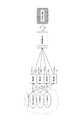
図1は、本開示のセンサ素子10の概略斜視図である。<Sensor element>
FIG. 1 is a schematic perspective view of the
センサ素子10は、被検流体中の検出対象の成分(検出対象成分)を検出することができる。センサ素子10は、基板11と、反応部12と、検出部13とを備える。図1に示すセンサ素子10は、第1、第2、第3及び第4反応部12a、12b、12c及び12dと、第1、第2、第3及び第4検出部13a、13b、13c及び13dを備える。 The
センサ素子10が備える反応部12の数は4つに限られない。センサ素子10は、2つ以上の反応部12を備えていればよい。検出部13の数は、反応部12の数に対応していればよい。複数の検出部13は、例えば複数の反応部12に対応して基板11に配置される。図1では、複数の検出部13の記載を省略している。 The number of
以下、本明細書において、第1〜4反応部12a〜dのそれぞれを区別しない場合には、反応部12と表記する。第1〜4検出部13a〜dのそれぞれを区別しない場合には、検出部13と表記する。 Hereinafter, in the present specification, when each of the first to
基板11は、変形可能な部材であればよい。基板11は、例えばダイアフラムとして機能する薄い基板であればよい。具体的には、基板11は、例えばn型のSi基板等であればよい。 The
反応部12は、特定の成分に反応することができる。反応部12は、基板11上に配置される。反応部12は、例えば膜状の部材であればよい。反応部12は、特定の成分を吸着することによって変形する材料で構成されればよい。反応部12は、例えば、ポリスチレン、クロロプレンゴム、ポリメチルメタクリレート又はニトロセルロース等の材料で形成されればよい。 The
各反応部12を異なる材料で形成すれば、特定の成分に対して異なる選択性を各反応部12に付与することができる。すなわち、特定の成分に対する反応の度合いを変化させたり、異なる成分に反応させたりすることができる。ここで、選択性とは、特定の成分ごとに応じた反応性(又は感応性)をいう。具体的に、選択性とは、1つの反応部12に複数種類の成分を同濃度で供給したときの、反応部12の変形に対する各成分の寄与率である。 If each
検出部13は、反応部12が特定の成分に反応したことを検知することができる。検出部13は、例えばピエゾ抵抗素子であり、基板11に配されていればよい。検出部13は、例えば4つのピエゾ抵抗素子を有してホイートストーンブリッジ回路を構成していればよい。検出部13は、基板11に、例えばボロン(B)を拡散させて形成すればよい。 The
センサ素子10は、上記の構成を有することによって、特定の成分を検出することができる。具体的には、まず、反応部12が特定の成分に反応して変形し、反応部12の変形に応じて基板11が変形する。そして、基板11の変形によって検出部13に応力が印加され、検出部13の電気抵抗値が変化する。その結果、検出部13の出力が変動し、センサ素子10は特定の成分を検出することができる。 By having the above configuration, the
したがって、例えば、センサ素子10に被検流体を供給することによって、被検流体中に検出対象成分が含まれていれば、センサ素子10は、検出対象成分を検出することができる。 Therefore, for example, by supplying the test fluid to the
検出部13は、特定の成分との反応に応じた電気信号を出力する。本明細書において、検出部13が出力する信号を、以下「センサ出力」とも称する。センサ出力は、例えば電圧値であればよい。 The
<センサ装置>
図2は、センサ装置20の概略構成を示す機能ブロック図である。<Sensor device>
FIG. 2 is a functional block diagram showing a schematic configuration of the
図2のセンサ装置20は、図1のセンサ素子10を含む。すなわち、図2に示すように、センサ装置20は、制御部21と、記憶部22と、センサ素子10(検出部13)とを備える。センサ装置20は、反応部12における成分との反応状態に基づき、被検流体中に含まれる成分に関する値を算出することができる。例えば、センサ装置20は、被検流体中に含まれる検出対象成分の濃度を算出することができる。ただし、被検流体中に含まれる成分に関する値は、濃度に限られず、数値として表される指標等の任意の値であってよい。また、被検体中に含まれる成分に関する値は、検出対象成分に関する値に限られず、例えば検出対象成分を除いた他の成分に関する値であってよい。本明細書では、センサ装置20が、被検流体中に含まれる検出対象成分の濃度を算出するとして、以下説明する。 The
制御部21は、センサ装置20の各機能ブロックをはじめとして、センサ装置20の全体を制御及び管理するプロセッサである。制御部21は、制御手順を規定したプログラムを実行するCPU(Central processing Unit)等のプロセッサで構成される。このようなプログラムは、例えば、記憶部22、又はセンサ装置20に接続された外部の記憶媒体等に格納されればよい。 The
記憶部22は、半導体メモリ又は磁気メモリ等で構成され得る。記憶部22は、各種の情報、及び/又はセンサ装置20を動作させるためのプログラム等を記憶することができる。記憶部22は、ワークメモリとして機能してもよい。 The
<検出対象成分の測定原理>
被検流体に含まれる検出対象成分の測定原理について説明する。検出対象成分の濃度を測定するには、主に、検出対象成分の濃度を算出するステップと、濃度算出のための数式を生成するステップがある。<Measurement principle of the component to be detected>
The measurement principle of the component to be detected contained in the test fluid will be described. To measure the concentration of the component to be detected, there are mainly a step of calculating the concentration of the component to be detected and a step of generating a mathematical formula for calculating the concentration.
本実施形態では、制御部21が、検出対象成分の濃度を算出する場合の一例について説明する。ここでは、被検流体は、気体(ガス)であるとして説明する。 In this embodiment, an example in which the
図3A及び図3Bは、センサ装置20による測定原理の一例に関する説明図である。図3Aに基づいて、被検流体中の検出対象成分の濃度の算出について説明する。 3A and 3B are explanatory views regarding an example of the measurement principle by the
制御部21は、図3Aに示すように、各検出部13のセンサ出力を所定の数式に代入して演算を行ない、検出対象成分の濃度を算出する。所定の数式は、例えば重回帰分析等の手法により、検出対象成分の濃度を算出する回帰式として得られる。 As shown in FIG. 3A, the
図3Bは、重回帰分析による回帰係数の算出について説明する図である。図3Bに基づいて、回帰式の算出方法を説明する。 FIG. 3B is a diagram illustrating the calculation of the regression coefficient by the multiple regression analysis. A method of calculating the regression equation will be described with reference to FIG. 3B.
まず、回帰係数を算出するために、複数のリファレンスガスを準備する。複数のリファレンスガスは、被検流体に含まれていると想定される成分(想定成分)を有するガスである。重回帰分析を行なうために、複数のリファレンスガスは予め定めた濃度で想定成分を有しており、想定成分の濃度は各リファレンスガスで異なる。次に、センサ素子10の反応部12に複数のリファレンスガスを供給する。そして、各検出部13から各反応部12の選択性に応じたセンサ出力が得られる。その結果、各検出部13のセンサ出力に基づき、重回帰分析が行われ、回帰係数を算出することができる。複数のリファレンスガスは、重回帰分析を行なうのに十分な種類のガスを準備する。 First, a plurality of reference gases are prepared in order to calculate the regression coefficient. The plurality of reference gases are gases having components (assumed components) that are assumed to be contained in the test fluid. In order to perform multiple regression analysis, a plurality of reference gases have assumed components at predetermined concentrations, and the concentrations of the assumed components are different for each reference gas. Next, a plurality of reference gases are supplied to the
回帰式の生成について、センサ素子10が、第1、2反応部12a、bを有する場合を例に、より具体的に説明する。 The generation of the regression equation will be described more specifically by taking the case where the
第1,2反応部12a,bの検出対象成分の選択性を、それぞれA1及びA2とし、第1,2反応部12a,bのノイズ成分の選択性を、それぞれB1及びB2としたときに、第1,2検出部13a,bのセンサ出力(Y1、Y2)は、検出対象成分の濃度をXA、ノイズ成分の濃度をXBとして、下式(式1)で表わすことができる。本明細書において、ノイズ成分は、被検流体に含まれる検出対象成分を除いた成分である。式1の定数項(Z1、Z2)は、例えば、何も供給していない状態でも製造誤差などによって出力される信号等である。
Y1=(A1×XA)+(B1×XB)+Z1(定数項)
Y2=(A2×XA)+(B2×XB)+Z2(定数項)…式1The selectivity of the detection target component of thefirst and
Y1 = (A1 x XA ) + (B1 x XB ) + Z1 (constant term)
Y2 = (A2 x XA ) + (B2 x XB ) + Z2 (constant term) ...
式1で得られる複数のリファレンスガスに基づいた第1,2検出部13a,bのセンサ出力(Y1、Y2)と、検出対象成分の濃度(XA)とから、重回帰分析を行ない、下記の回帰式(式2)における回帰係数であるα、β及びγを算出する。
XA=α×Y1+β×Y2+γ…式2Multiple regression analysis is performed fromthe sensor outputs (Y 1 , Y2 ) of the first and
XA = α × Y1 + β × Y2 + γ…
重回帰分析は、反応部12の選択性(A1、A2、B1、B2)が既知の場合には、リファレンスガスを測定する代わりに、コンピュータを使用したシミュレーションによって行なってもよい。選択性は、想定成分ごとに各想定成分のみから成るガス(単体ガス)を準備し、単体ガスごとのセンサ出力を比較することによって求めることができる。If the selectivity of the reaction unit 12 (A1 , A2 , B1 , B2 ) is known, the multiple regression analysis may be performed by a computer simulation instead of measuring the reference gas. The selectivity can be obtained by preparing a gas (single gas) consisting of only each assumed component for each assumed component and comparing the sensor output of each assumed component.
以上より、回帰式(式2)を生成することができる。そして、センサ装置20(制御部21)は、被検流体が反応部12に供給されたときの各検出部13のセンサ出力を、回帰式(式2)のY1及びY2に代入して演算処理することによって検出対象成分の濃度を算出することができる。From the above, the regression equation (Equation 2) can be generated. Then, the sensor device 20 (control unit 21) substitutes the sensor output of each
上記の説明では、説明の便宜上、式1および式2を簡略化して示しているが、実際のセンサ装置20では、測定条件などに合わせた式1および式2を使用すればよい。例えば、上記の説明では、ノイズ成分の項は1つであるが、ノイズ成分ごとに項を設定してもよい。上記の説明では、反応部12が2つの場合なので、Y1およびY2しか表れないが、実際には、反応部12の数(n)に応じて、Ym(m=1,2,…n)を設定すればよい。In the above description, the
ここで、センサ装置20を使用する場合、被検流体の供給の仕方よって、測定結果が真の値からずれることが想定される。例えば、測定雰囲気に影響を受けて、検出対象成分が実際に被検流体中に含まれる濃度よりも少ない濃度でセンサ素子10に供給される場合がある。センサ素子10は同一濃度の被検流体が供給されたとしても、反応部12の変化が若干異なったり、反応部12の変化が同一であっても検出部13の出力が若干異なったりする場合がある。したがって、センサ素子10の測定結果の正確度が低下することが懸念される。そこで、本開示の発明者は、上述の原理を用いた検出対象成分の濃度算出についてコンピュータを用いたシミュレーションを行い、各反応部12の選択性が与える測定結果の正確度への影響を検証した。 Here, when the
<シミュレーション及び考察>
以下、発明者が行ったシミュレーションについて説明する。<Simulation and consideration>
Hereinafter, the simulation performed by the inventor will be described.
まず、基本的なシミュレーションの方法について説明する。シミュレーションは、第1ステップとして、反応部12の選択性(式1で示されたA1、A2、B1、B2)を任意の固定値に、被検流体成分の濃度(式1で示されたXA、XB)を任意の変数に設定して式1に代入し、センサ出力(式1、2で示されたY1、Y2)を求める。実際の測定を想定して、式1から算出されるセンサ出力(Y1、Y2)には、測定誤差を乗じている。そして、被検流体成分の濃度(XA)とセンサ出力(Y1、Y2)とのデータ群に基づいて式2を求める。データ群は、式2を求めるのに十分な数のデータを集める。First, the basic simulation method will be described. In the simulation, as the first step, the selectivity of the reaction unit 12 (A1 , A2 , B1 , B2 shown in Equation 1) is set to an arbitrary fixed value, and the concentration of the fluid component to be tested (in Equation 1). The indicated XA and XB ) are set in arbitrary variables and substituted into
第2ステップとして、再度、反応部12の選択性(A1、A2、B1、B2)を任意の固定値(第1ステップと同一値)に、被検流体成分の濃度(XA、XB)を任意の変数(XAは第1ステップと同一値、XBは第1ステップと異なる値)に設定して式1に代入する。そして、式1から得られた検出部13のセンサ出力(Y1、Y2)を式2に代入して被検流体成分の濃度(XA)を算出する。実際の測定を想定して、式2に代入するセンサ出力(Y1、Y2)には、第1ステップと異なる測定誤差を乗じている。As the second step, again, the selectivity of the reaction unit 12 (A1 , A2 , B1 , B2 ) is set to an arbitrary fixed value (the same value as in the first step), and the concentration of the fluid component to be tested (XA). , XB ) is set to an arbitrary variable (XA is the same value as the first step, XB is a different value from the first step) and is assigned to
第3ステップとして、第2ステップで設定した被検流体成分の濃度(XA)と、第2ステップで算出した被検流体成分の濃度(XA)との誤差(後述する濃度算出誤差)を求める。As the third step, the error between the concentration of the test fluid component (XA ) set in the second step and the concentration of the test fluid component (XA ) calculated in the second step (concentration calculation error described later) is calculated. Ask.
第4ステップとして、反応部12の選択性(A1、A2、B1、B2)の値を変更して、再度第1ステップから第3ステップまでを繰り返す。As the fourth step,the values of the selectivity (A 1 , A2 , B1 , B2 ) of the
以上が、基本的なシミュレーションの方法である。 The above is the basic simulation method.
次に、発明者が行った具体的なシミュレーションの内容について説明する。 Next, the contents of the specific simulation performed by the inventor will be described.
(第1のシミュレーション)
発明者は、まず、第1のシミュレーションを行なった。第1のシミュレーションでは、2つのチャネルを有するセンサ装置20を想定して、第1チャネル及び第2チャネルの選択性について検証した。(First simulation)
The inventor first performed the first simulation. In the first simulation, the selectivity of the first channel and the second channel was verified assuming the
本明細書において、チャネルとは、反応部と検出部とを1組として捉えたときの表現である。言い換えれば、1つのチャネルは、1つの反応部と1つの検出部を含む概念である。 In the present specification, the channel is an expression when the reaction part and the detection part are regarded as one set. In other words, one channel is a concept that includes one reaction part and one detection part.
(選択性の設定)
第1のシミュレーションでは、第1チャネルの検出対象成分とノイズ成分との選択性の比を、x対1に設定し、xの値を1から30の範囲で変化させた。第2チャネルの検出対象成分とノイズ成分との選択性の比を、1対yに設定し、yの値を1から30の範囲で変化させた。(Selectivity setting)
In the first simulation, the ratio of selectivity between the detection target component and the noise component of the first channel was set to x: 1, and the value of x was changed in the range of 1 to 30. The ratio of selectivity between the detection target component and the noise component of the second channel was set to 1: y, and the value of y was changed in the range of 1 to 30.
(被検流体成分濃度の設定)
第1のシミュレーションでは、被検流体中に含まれている微量の検出対象成分を測定することを想定し、被検流体中の各成分の濃度を設定した。具体的には、検出対象成分の濃度を0.1ppm以上10ppm以下の範囲で変化させた。ノイズ成分の濃度は、中心値を100ppmとする一様分布(50%〜150%の範囲)に基づいた乱数を設定した。(Setting of test fluid component concentration)
In the first simulation, the concentration of each component in the test fluid was set on the assumption that a small amount of the component to be detected contained in the test fluid was measured. Specifically, the concentration of the component to be detected was changed in the range of 0.1 ppm or more and 10 ppm or less. The density of the noise component was set to a random number based on a uniform distribution (range of 50% to 150%) with a median of 100 ppm.
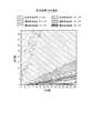
(結果と考察)
図4及び図5は、第1のシミュレーションの結果を示す図である。図4は、測定誤差を1%とした場合のシミュレーション結果を示す。図5は、測定誤差を5%とした場合のシミュレーション結果を示す。図4及び図5において、縦軸はyの値、横軸はxの値を示す。図4及び図5は、濃度算出誤差を、1%ごとに異なるハッチングで示す。ただし、図4では、濃度算出誤差が7%以上の領域については、ハッチングを省略している。同様に、図5では、濃度算出誤差が15%以上の領域については、ハッチングを省略している。測定誤差は、上記の数値を中心値とした正規分布に基づいた乱数としている。(Results and discussion)
4 and 5 are diagrams showing the results of the first simulation. FIG. 4 shows a simulation result when the measurement error is 1%. FIG. 5 shows a simulation result when the measurement error is 5%. In FIGS. 4 and 5, the vertical axis represents the value of y and the horizontal axis represents the value of x. 4 and 5 show the concentration calculation error with different hatching for each 1%. However, in FIG. 4, hatching is omitted in the region where the concentration calculation error is 7% or more. Similarly, in FIG. 5, hatching is omitted in the region where the concentration calculation error is 15% or more. The measurement error is a random number based on a normal distribution centered on the above numerical value.
図4及び図5を参照すると、xの値が大きいほど、濃度算出誤差が小さい。すなわち、第1チャネルの検出対象成分に対する選択性が高いほど、検出対象成分の測定結果の正確度が高まる。図4及び図5を参照すると、xの値が一定であれば、yの値によらず、濃度算出誤差はほぼ一定である。すなわち、第2チャネルの検出対象成分とノイズ成分との選択性の比は、検出対象成分の測定結果の正確度に与える影響が小さい。 With reference to FIGS. 4 and 5, the larger the value of x, the smaller the concentration calculation error. That is, the higher the selectivity for the detection target component of the first channel, the higher the accuracy of the measurement result of the detection target component. With reference to FIGS. 4 and 5, if the value of x is constant, the concentration calculation error is substantially constant regardless of the value of y. That is, the ratio of the selectivity of the detection target component and the noise component of the second channel has a small influence on the accuracy of the measurement result of the detection target component.
したがって、センサ装置20及びセンサ素子10の検出対象成分の測定結果の正確度を向上させるには、反応部12のうちの1つは、検出対象成分に対する選択性が高いことが有効であることが分かった。言い換えれば、第1反応部12aは、第2反応部12bよりも検体中の検出対象成分に対する反応性が高く、かつ検出対象成分に対する選択性は、検体中の検出対象成分以外のノイズ成分に対する選択性よりも高いと、センサ装置20及びセンサ素子10の検出対象成分の測定結果の正確度を向上させることができる。 Therefore, in order to improve the accuracy of the measurement result of the detection target component of the
(第2のシミュレーション)
次に、発明者は、第2のシミュレーションを行なった。第2のシミュレーションでは、第1チャネルの選択性を固定した場合の第2チャネルの選択性について検証した。(Second simulation)
Next, the inventor performed a second simulation. In the second simulation, the selectivity of the second channel when the selectivity of the first channel was fixed was verified.
(選択性の設定)
第2のシミュレーションでは、第1チャネルの検出対象成分とノイズ成分との選択性の比を10対1に固定した。第2チャネルの検出対象成分とノイズ成分との選択性の比をz対wに設定し、z及びwの値をそれぞれ1から30の範囲で変化させた。(Selectivity setting)
In the second simulation, the ratio of selectivity between the detection target component and the noise component of the first channel was fixed at 10: 1. The ratio of selectivity between the detection target component and the noise component of the second channel was set to z to w, and the values of z and w were changed in the range of 1 to 30, respectively.
(被検流体成分濃度の設定)
第2のシミュレーションでは、第1のシミュレーションと同様に、検出対象成分の濃度及びノイズ成分の濃度を設定した。(Setting of test fluid component concentration)
In the second simulation, the concentration of the detection target component and the concentration of the noise component were set as in the first simulation.
(結果と考察)
図6及び図7は、第2のシミュレーションの結果を示す図である。図6は、測定誤差を1%とした場合のシミュレーション結果を示す。図7は、測定誤差を5%とした場合のシミュレーション結果を示す。図6及び図7において、縦軸はwの値、横軸はzの値を示す。図6及び図7は、濃度算出誤差を、1%ごとに異なるハッチングで示す。ただし、図6では、濃度算出誤差が15%以上の領域については、ハッチングを省略している。同様に、図7では、濃度算出誤差が25%以上の領域については、ハッチングを省略している。測定誤差は、上記の数値を中心値とした正規分布に基づいた乱数としている。(Results and discussion)
6 and 7 are diagrams showing the results of the second simulation. FIG. 6 shows a simulation result when the measurement error is 1%. FIG. 7 shows a simulation result when the measurement error is 5%. In FIGS. 6 and 7, the vertical axis represents the value of w and the horizontal axis represents the value of z. 6 and 7 show the concentration calculation error with different hatching for each 1%. However, in FIG. 6, hatching is omitted in the region where the concentration calculation error is 15% or more. Similarly, in FIG. 7, hatching is omitted in the region where the concentration calculation error is 25% or more. The measurement error is a random number based on a normal distribution centered on the above numerical value.
図6及び図7を参照すると、zの値が大きいほど、またwの値が小さいほど、濃度算出誤差が大きい。すなわち、第2チャネルのノイズ成分に対する選択性が小さいほど、検出対象成分の測定結果の正確度は低下する。言い換えれば、第2チャネルのノイズ成分に対する選択性が大きいほど、検出対象成分の測定結果の正確度を向上させることができる。 With reference to FIGS. 6 and 7, the larger the value of z and the smaller the value of w, the larger the concentration calculation error. That is, the smaller the selectivity for the noise component of the second channel, the lower the accuracy of the measurement result of the detection target component. In other words, the greater the selectivity for the noise component of the second channel, the more accurate the measurement result of the detection target component can be improved.
したがって、センサ装置20及びセンサ素子10の検出対象成分の測定結果の正確度を向上させるには、反応部12のうちの1つは、ノイズ成分に対する選択性が高いことが有効であることが分かった。言い換えれば、第2反応部12bの前記検出対象成分に対する反応性は、ノイズ成分に対する反応性よりも低いと、センサ装置20及びセンサ素子10の検出対象成分の測定結果の正確度を向上させることができる。 Therefore, in order to improve the accuracy of the measurement result of the detection target component of the
(第3のシミュレーション)
次に、発明者は、第3のシミュレーションを行なった。第3のシミュレーションでは、より現実的な測定を想定し、チャネルの数量および各チャネルの選択性について検証した。(Third simulation)
Next, the inventor performed a third simulation. In the third simulation, the quantity of channels and the selectivity of each channel were verified assuming more realistic measurements.
第3のシミュレーションでは、例えば、人間の呼気の測定を想定し、検出対象成分としてアセトンを想定した。上記想定を考慮して、ノイズ成分についても、図8に示すように、複数種類のノイズ成分を想定した。第3のシミュレーションでは、ノイズ成分を、濃度に応じてビッグノイズ及びスモールノイズの2種類に分類した。ビッグノイズは、被検流体中において、スモールノイズよりも含有される濃度が高い。例えば、ビッグノイズは、被検流体において所定濃度以上のガスであり、スモールノイズは、被検流体において所定濃度未満のガスであると定義してよい。他の例として、例えば、ビッグノイズは、被検流体において検出対象成分の濃度の最大値よりも所定倍数以上の濃度でガスであり、スモールノイズは、被検流体において検出対象成分の濃度の最大値よりも所定倍数未満の濃度のガスであると定義してもよい。第3のシミュレーションでは、ノイズ成分のうち、酸素(O2)、二酸化炭素(CO2)及び水蒸気(H2O)をビッグノイズとし、その他のノイズ成分をスモールノイズと分類した。In the third simulation, for example, measurement of human breath was assumed, and acetone was assumed as a component to be detected. In consideration of the above assumptions, as shown in FIG. 8, a plurality of types of noise components are assumed for the noise components. In the third simulation, the noise components were classified into two types, big noise and small noise, according to the density. The concentration of big noise in the test fluid is higher than that of small noise. For example, big noise may be defined as a gas having a concentration equal to or higher than a predetermined concentration in the test fluid, and small noise may be defined as a gas having a concentration lower than a predetermined concentration in the test fluid. As another example, for example, big noise is a gas at a concentration equal to or higher than a predetermined multiple of the maximum concentration of the component to be detected in the test fluid, and small noise is the maximum concentration of the component to be detected in the test fluid. It may be defined as a gas having a concentration less than a predetermined multiple of the value. In the third simulation, among the noise components, oxygen (O2 ), carbon dioxide (CO2 ) and water vapor (H2 O) were classified as big noise, and other noise components were classified as small noise.
(選択性の設定)
第3のシミュレーションでは、第1、2のシミュレーションの結果を参考に、第1チャネルが、検出対象成分に対して、最も高い選択性を示すように設定した。図9に示す例では、第1チャネルのアセトンに対する選択性は30に設定されている。第2チャネル以降のいずれかのチャネルは、検出対象成分に対してノイズ成分の選択性が高くなるように設定した。図9に示す例では、第2チャネルのアセトンに対する選択性を3.11に設定し、ノイズ成分の選択性をそれ以上に設定している。(Selectivity setting)
In the third simulation, the first channel was set to show the highest selectivity for the component to be detected with reference to the results of the first and second simulations. In the example shown in FIG. 9, the selectivity of the first channel for acetone is set to 30. Any of the second and subsequent channels was set so that the selectivity of the noise component with respect to the detection target component was high. In the example shown in FIG. 9, the selectivity of the second channel with respect to acetone is set to 3.11, and the selectivity of the noise component is set higher than that.
図9は、各チャネルの選択性の設定例の一例を示す図である。図9の各行は被検流体中の各成分を示し、各列はチャネル番号を示す。図9は、チャネル数が16の場合の一例を示す。図9の表に示される数値は、各チャネルにおける、各成分に対する選択性を示す。この数値が大きいほど、選択性が高いことを意味する。 FIG. 9 is a diagram showing an example of setting the selectivity of each channel. Each row in FIG. 9 shows each component in the test fluid, and each column shows the channel number. FIG. 9 shows an example when the number of channels is 16. The numbers shown in the table of FIG. 9 indicate the selectivity for each component in each channel. The larger this number is, the higher the selectivity is.
以下、本明細書では、第1チャネルの検出対象成分に対する選択性(図9におけるS1で示される選択性)を「第1信号選択性」という。第1チャネルのビッグノイズに対する選択性(図9におけるS2で示される選択性)を、「第1ビッグノイズ選択性」という。第1チャネルのスモールノイズに対する選択性(図9におけるS3で示される選択性)を、「第1スモールノイズ選択性」という。第2チャネル以降(図9では、第2チャネルから第16チャネル)の検出対象成分に対する選択性(図9におけるS4で示される選択性)を、「第2信号選択性」という。第2チャネル以降のビッグノイズに対する選択性(図9におけるS5で示される選択性)を、「第2ビッグノイズ選択性」という。第2チャネル以降のスモールノイズに対する選択性(図9におけるS6で示される選択性)を、「第2スモールノイズ選択性」という。 Hereinafter, in the present specification, the selectivity for the detection target component of the first channel (selectivity shown by S1 in FIG. 9) is referred to as "first signal selectivity". The selectivity for big noise of the first channel (selectivity shown in S2 in FIG. 9) is referred to as "first big noise selectivity". The selectivity for small noise of the first channel (selectivity shown in S3 in FIG. 9) is referred to as "first small noise selectivity". The selectivity for the detection target component (selectivity shown in S4 in FIG. 9) of the second and subsequent channels (
具体的には、第3のシミュレーションでは、「第1信号選択性」を所定の値に設定した。「第1ビッグノイズ選択性」、「第1スモールノイズ選択性」、「第2信号選択性」、「第2ビッグノイズ選択性」及び「第2スモールノイズ選択性」のうち、いずれか1つを、0.000−1.000(以下、0−1と表記する)の範囲でコンピュータに自動的に決定させた。上記いずれか1つ以外の選択性については、1.000−5.000(以下、1−5と表記する)の範囲でコンピュータに自動的に決定させた。第3のシミュレーションは、チャネル数を2から16の範囲で変化させて行った。 Specifically, in the third simulation, the "first signal selectivity" was set to a predetermined value. One of "1st big noise selectivity", "1st small noise selectivity", "2nd signal selectivity", "2nd big noise selectivity" and "2nd small noise selectivity" Was automatically determined by the computer in the range of 0.000-1.000 (hereinafter referred to as 0-1). The selectivity other than any one of the above was automatically determined by the computer in the range of 1.000-5.000 (hereinafter referred to as 1-5). The third simulation was performed by varying the number of channels in the range of 2 to 16.
(被検流体成分濃度の設定)
第3のシミュレーションでは、上記の通り人間の呼気の測定を想定し、検出対象成分の濃度を0.1ppm以上10ppm以下の範囲で変化させた。ノイズ成分についても、上記の通り、複数種類のノイズ成分を想定した。各ノイズ成分の濃度は、図8に示す数値を中心値とする一様分布(50%〜150%の範囲)に基づいた乱数を設定した。(Setting of test fluid component concentration)
In the third simulation, assuming the measurement of human breath as described above, the concentration of the component to be detected was changed in the range of 0.1 ppm or more and 10 ppm or less. As for the noise component, as described above, a plurality of types of noise components are assumed. For the concentration of each noise component, a random number based on a uniform distribution (range of 50% to 150%) centered on the numerical value shown in FIG. 8 was set.
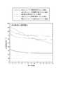
(結果と考察)
図10から図12は、第3のシミュレーションの結果を示す図である。図10は、第1信号選択性を10、測定誤差を1%とした場合のシミュレーション結果を示す。図11は、第1信号選択性を15、測定誤差を3%とした場合のシミュレーション結果を示す。図12は、第1信号選択性を20、測定誤差を5%とした場合のシミュレーション結果を示す。図10から図12において、縦軸はシミュレーションにおける重回帰分析による濃度算出誤差を、横軸はチャネル数を示す。図10から図12は、選択性の範囲を0−1に設定した項目ごとに結果を示す。測定誤差は、上記の数値を中心値とした正規分布に基づいた乱数としている。(Results and discussion)
10 to 12 are diagrams showing the results of the third simulation. FIG. 10 shows a simulation result when the first signal selectivity is 10 and the measurement error is 1%. FIG. 11 shows a simulation result when the first signal selectivity is 15 and the measurement error is 3%. FIG. 12 shows a simulation result when the first signal selectivity is 20 and the measurement error is 5%. In FIGS. 10 to 12, the vertical axis represents the concentration calculation error by multiple regression analysis in the simulation, and the horizontal axis represents the number of channels. 10 to 12 show the results for each item in which the selectivity range is set to 0-1. The measurement error is a random number based on a normal distribution centered on the above numerical value.
図10から図12のシミュレーション結果を参照すると、第1ビッグノイズ選択性を0−1の範囲にした場合、他の選択性を0−1の範囲にした場合と比較して、濃度算出誤差が小さい。すなわち、第1チャネルのビッグノイズに対する選択性が、第1チャネルのスモールノイズに対する選択性よりも低い場合、検出対象成分の測定結果の正確度が高まる。第1チャネルのビッグノイズに対する選択性が、第1チャネルと異なる他のチャネルのノイズ成分(ビッグノイズ及びスモールノイズ)に対する選択性よりも低い場合、検出対象成分の測定結果の正確度が高まる。 With reference to the simulation results of FIGS. 10 to 12, when the first big noise selectivity is set to the range of 0-1 and the other selectivity is set to the range of 0-1 the concentration calculation error is larger. small. That is, when the selectivity of the first channel for big noise is lower than the selectivity for small noise of the first channel, the accuracy of the measurement result of the detection target component is increased. When the selectivity of the first channel for big noise is lower than the selectivity for noise components (big noise and small noise) of other channels different from the first channel, the accuracy of the measurement result of the detection target component is increased.
したがって、センサ装置20及びセンサ素子10の検出対象成分の測定結果の正確度を向上させるには、第1チャネルのビッグノイズに対する選択性が、スモールノイズに対する選択性よりも低いと有効であることが分かった。言い換えれば、ノイズ成分を、第1ノイズ成分と、第1ノイズ成分よりも含有濃度の低い第2ノイズ成分とに分けたときに、第1反応部12aの第1ノイズ成分に対する反応性を、前記第2ノイズ成分に対する反応性よりも低く設定することによって、センサ装置20及びセンサ素子10の検出対象成分の測定結果の正確度を向上させることができる。 Therefore, in order to improve the accuracy of the measurement results of the detection target components of the
センサ装置20及びセンサ素子10の検出対象成分の測定結果の正確度を向上させるには、第1チャネルのビッグノイズに対する選択性が、第1チャネルと異なる他のチャネルのノイズ成分(ビッグノイズ及びスモールノイズ)に対する選択性よりも低いと有効であることが分かった。言い換えれば、第1反応部12aの第1ノイズ成分に対する反応性は、第1反応部12aと異なる他の反応部の反応性よりも低いと、センサ装置20及びセンサ素子10の検出対象成分の測定結果の正確度を向上させることができる。 In order to improve the accuracy of the measurement results of the detection target components of the
図10から図12のシミュレーション結果から、チャネル数が多いほど、検出対象成分の測定結果の正確度が高まる。 From the simulation results of FIGS. 10 to 12, the larger the number of channels, the higher the accuracy of the measurement result of the component to be detected.
上述したセンサ素子10は、多様な用途に使用することができる。センサ素子10は、例えば人の呼気における所定のガス成分の検出に使用できる。検出したガス成分の濃度は、人体に関する状態の推定に応用し得る。人体に関する状態の推定は、例えば人体における病気の進行の度合い等である。 The
センサ素子10は、例えば食品から発生する所定のガス成分の検出に使用できる。検出したガス成分の濃度は、食品のクオリティの推定に応用し得る。食品のクオリティは、食品に関する性質又は品質等であり、例えば食品の鮮度、食べごろ、熟成度、腐敗の度合い等を含んでよい。センサ素子10は、その他にも、例えば機器から発生する所定のガス成分の検出等、多様な用途に使用できる。 The
本開示を諸図面及び実施例に基づき説明してきたが、当業者であれば本開示に基づき種々の変形及び修正を行うことが容易であることに注意されたい。従って、これらの変形及び修正は本開示の範囲に含まれることに留意されたい。例えば、各構成部等に含まれる機能等は論理的に矛盾しないように再配置可能であり、複数の構成部を1つに組み合わせたり、或いは分割したりすることが可能である。 Although the present disclosure has been described based on the drawings and examples, it should be noted that those skilled in the art can easily make various modifications and modifications based on the present disclosure. It should be noted, therefore, that these modifications and modifications are within the scope of this disclosure. For example, the functions and the like included in each component can be rearranged so as not to be logically inconsistent, and a plurality of components can be combined or divided into one.
10 センサ素子
11 基板
12 反応部
13 検出部
20 センサ装置
21 制御部
22 記憶部10
Claims (5)
Translated fromJapanese前記複数の反応部は、第1反応部と、前記第1反応部よりも検体中の検出対象成分に対する反応性が低い第2反応部と、を有し、
前記第1反応部の前記検出対象成分に対する反応性は、検体中の前記検出対象成分以外のノイズ成分に対する反応性よりも高い、
センサ素子。A substrate and a plurality of reaction portions arranged on the substrate and reacting with a specific component are provided.
The plurality of reaction parts include a first reaction part and a second reaction part having a lower reactivity to the detection target component in the sample than the first reaction part.
The reactivity of the first reaction unit with respect to the detection target component is higher than the reactivity with noise components other than the detection target component in the sample.
Sensor element.
前記第1反応部の前記第1ノイズ成分に対する反応性は、前記第2ノイズ成分に対する反応性よりも低い、請求項1又は2に記載のセンサ素子。The noise component includes a first noise component and a second noise component having a concentration lower than that of the first noise component.
The sensor element according to claim 1 or 2, wherein the reactivity of the first reaction unit to the first noise component is lower than the reactivity to the second noise component.
前記複数の反応部の反応に応じて前記センサ素子から出力される信号に基づいて、検体中の成分に関する値を算出する制御部と、
を備え、
前記複数の反応部は、第1反応部と、前記第1反応部よりも前記検出対象成分に対する反応性が低い第2反応部と、を有し、
前記第1反応部の前記検出対象成分に対する反応性は、検体中の前記検出対象成分以外のノイズ成分に対する反応性よりも高い、
センサ装置。A sensor element comprising a substrate and a plurality of reaction portions arranged on the substrate and reacting with a specific component.
A control unit that calculates values related to components in a sample based on signals output from the sensor element in response to the reactions of the plurality of reaction units, and a control unit.
With
The plurality of reaction parts include a first reaction part and a second reaction part having a lower reactivity to the detection target component than the first reaction part.
The reactivity of the first reaction unit with respect to the detection target component is higher than the reactivity with noise components other than the detection target component in the sample.
Sensor device.
Applications Claiming Priority (3)
| Application Number | Priority Date | Filing Date | Title |
|---|---|---|---|
| JP2016169403 | 2016-08-31 | ||
| JP2016169403 | 2016-08-31 | ||
| JP2018537335AJPWO2018043549A1 (en) | 2016-08-31 | 2017-08-30 | Sensor element and sensor device |
Related Parent Applications (1)
| Application Number | Title | Priority Date | Filing Date |
|---|---|---|---|
| JP2018537335ADivisionJPWO2018043549A1 (en) | 2016-08-31 | 2017-08-30 | Sensor element and sensor device |
Publications (2)
| Publication Number | Publication Date |
|---|---|
| JP2021039110Atrue JP2021039110A (en) | 2021-03-11 |
| JP7382301B2 JP7382301B2 (en) | 2023-11-16 |
Family
ID=61300976
Family Applications (2)
| Application Number | Title | Priority Date | Filing Date |
|---|---|---|---|
| JP2018537335APendingJPWO2018043549A1 (en) | 2016-08-31 | 2017-08-30 | Sensor element and sensor device |
| JP2020183932AActiveJP7382301B2 (en) | 2016-08-31 | 2020-11-02 | Sensor element and sensor device |
Family Applications Before (1)
| Application Number | Title | Priority Date | Filing Date |
|---|---|---|---|
| JP2018537335APendingJPWO2018043549A1 (en) | 2016-08-31 | 2017-08-30 | Sensor element and sensor device |
Country Status (4)
| Country | Link |
|---|---|
| US (1) | US20190195763A1 (en) |
| JP (2) | JPWO2018043549A1 (en) |
| CN (1) | CN109642863A (en) |
| WO (1) | WO2018043549A1 (en) |
Families Citing this family (1)
| Publication number | Priority date | Publication date | Assignee | Title |
|---|---|---|---|---|
| JP2020046252A (en)* | 2018-09-18 | 2020-03-26 | 日本精工株式会社 | Mixed gas concentration measurement method, gas sensor, lubricant degradation state evaluation method |
Citations (6)
| Publication number | Priority date | Publication date | Assignee | Title |
|---|---|---|---|---|
| JPH07110312A (en)* | 1993-10-08 | 1995-04-25 | Nippon Sanso Kk | Measuring method of component gas |
| JP2008268170A (en)* | 2007-03-22 | 2008-11-06 | Shinshu Univ | sensor |
| JP2008275383A (en)* | 2007-04-26 | 2008-11-13 | Hitachi Engineering & Services Co Ltd | Method and device for measuring concentration of mixed component system, and operation control system of energy-saving or exhaust-cleaning facility using device |
| WO2012165182A1 (en)* | 2011-05-27 | 2012-12-06 | 株式会社 エヌ・ティ・ティ・ドコモ | Living organism gas detection device and living organism gas detection method |
| US20130111977A1 (en)* | 2011-11-04 | 2013-05-09 | Stichting Imec Nederland | Chemical Sensor |
| JP2016001126A (en)* | 2014-06-11 | 2016-01-07 | 株式会社タニタ | Biogas detection apparatus, method, and program |
Family Cites Families (8)
| Publication number | Priority date | Publication date | Assignee | Title |
|---|---|---|---|---|
| JPH05203598A (en)* | 1992-01-23 | 1993-08-10 | Tokyo Gas Co Ltd | Mixed gas detector |
| TWI343997B (en)* | 2007-06-07 | 2011-06-21 | Univ Chung Yuan Christian | Multi-ion potential system and fabrication thereof |
| JP4873420B2 (en)* | 2007-08-13 | 2012-02-08 | リンナイ株式会社 | Gas concentration detection apparatus and gas concentration detection method |
| CN101368921B (en)* | 2008-09-08 | 2011-11-16 | 无锡尚沃生物科技有限公司 | High sensitivity and high-selective gas transducer |
| GB2476122A (en)* | 2009-12-14 | 2011-06-15 | Graviner Ltd Kidde | MOS gas sensor apparatus and method of use |
| GB2519937B (en)* | 2013-09-05 | 2016-07-27 | Kanichi Res Services Ltd | Electrochemical sensor |
| US10139383B2 (en)* | 2013-12-02 | 2018-11-27 | TricornTech Taiwan | Real-time air monitoring with multiple sensing modes |
| US9927385B2 (en)* | 2014-05-15 | 2018-03-27 | Ohio State Innovation Foundation | Active control guards and rationometric calibration and reconstruction for use with electrical capacitance volume tomography |
- 2017
- 2017-08-30JPJP2018537335Apatent/JPWO2018043549A1/enactivePending
- 2017-08-30WOPCT/JP2017/031122patent/WO2018043549A1/ennot_activeCeased
- 2017-08-30CNCN201780052993.9Apatent/CN109642863A/enactivePending
- 2017-08-30USUS16/329,071patent/US20190195763A1/ennot_activeAbandoned
- 2020
- 2020-11-02JPJP2020183932Apatent/JP7382301B2/enactiveActive
Patent Citations (6)
| Publication number | Priority date | Publication date | Assignee | Title |
|---|---|---|---|---|
| JPH07110312A (en)* | 1993-10-08 | 1995-04-25 | Nippon Sanso Kk | Measuring method of component gas |
| JP2008268170A (en)* | 2007-03-22 | 2008-11-06 | Shinshu Univ | sensor |
| JP2008275383A (en)* | 2007-04-26 | 2008-11-13 | Hitachi Engineering & Services Co Ltd | Method and device for measuring concentration of mixed component system, and operation control system of energy-saving or exhaust-cleaning facility using device |
| WO2012165182A1 (en)* | 2011-05-27 | 2012-12-06 | 株式会社 エヌ・ティ・ティ・ドコモ | Living organism gas detection device and living organism gas detection method |
| US20130111977A1 (en)* | 2011-11-04 | 2013-05-09 | Stichting Imec Nederland | Chemical Sensor |
| JP2016001126A (en)* | 2014-06-11 | 2016-01-07 | 株式会社タニタ | Biogas detection apparatus, method, and program |
Also Published As
| Publication number | Publication date |
|---|---|
| CN109642863A (en) | 2019-04-16 |
| WO2018043549A1 (en) | 2018-03-08 |
| JPWO2018043549A1 (en) | 2019-06-24 |
| JP7382301B2 (en) | 2023-11-16 |
| US20190195763A1 (en) | 2019-06-27 |
Similar Documents
| Publication | Publication Date | Title |
|---|---|---|
| EP1606639B1 (en) | Method and system for processing a multi-channel measurement of magnetic fields | |
| US11715049B2 (en) | Information processing device and method | |
| CA2637188A1 (en) | Measuring apparatuses and methods of using them | |
| JP2009505062A5 (en) | ||
| JP7112134B2 (en) | BIOGAS DETECTION DEVICE, METHOD, AND PROGRAM | |
| US20220036223A1 (en) | Processing apparatus, processing method, and non-transitory storage medium | |
| JP7382301B2 (en) | Sensor element and sensor device | |
| CN111735501B (en) | Temperature and humidity measuring method for environmental test facility equipment | |
| JP4374723B2 (en) | Odor identification device | |
| US12072325B2 (en) | Information processing apparatus, information processing method, and program | |
| CN119619057A (en) | A method and system for detecting glucose solution concentration based on near infrared spectroscopy | |
| WO2020170770A1 (en) | Detection device and sensor calibration method | |
| KR20240138482A (en) | Method and Apparatus for Determining Concentration of Selected Component in Detected Gas | |
| CN114112966A (en) | Gas sensor testing device, method, machine readable storage medium and processor | |
| CN113655093B (en) | Gas concentration detection method, device, equipment and medium | |
| Imamura et al. | The primary dynamic gravimetric system for gas mass flow measurement | |
| JP2006349636A (en) | Weight measuring method | |
| US10316690B2 (en) | Method for validation of an investigated sensor and corresponding machine | |
| JP7056747B2 (en) | Information processing equipment, processing equipment, information processing method, processing method, determination method, and program | |
| JP7268509B2 (en) | Anomaly degree calculation method and anomaly degree calculation computer program | |
| JP7099623B2 (en) | Information processing equipment, information processing methods, and programs | |
| US20230118020A1 (en) | Data generation apparatus, data generation method, and recording medium | |
| CN111380616A (en) | Separated temperature measuring module | |
| JP2007218669A (en) | Abnormality detection apparatus and program | |
| Chaitas et al. | Gas identification method by microcontroller-based analysis of two-dimensional sensor behavior |
Legal Events
| Date | Code | Title | Description |
|---|---|---|---|
| A521 | Request for written amendment filed | Free format text:JAPANESE INTERMEDIATE CODE: A523 Effective date:20201201 | |
| A621 | Written request for application examination | Free format text:JAPANESE INTERMEDIATE CODE: A621 Effective date:20201201 | |
| A977 | Report on retrieval | Free format text:JAPANESE INTERMEDIATE CODE: A971007 Effective date:20211117 | |
| A131 | Notification of reasons for refusal | Free format text:JAPANESE INTERMEDIATE CODE: A131 Effective date:20220104 | |
| A521 | Request for written amendment filed | Free format text:JAPANESE INTERMEDIATE CODE: A523 Effective date:20220303 | |
| A02 | Decision of refusal | Free format text:JAPANESE INTERMEDIATE CODE: A02 Effective date:20220802 | |
| A521 | Request for written amendment filed | Free format text:JAPANESE INTERMEDIATE CODE: A523 Effective date:20221101 | |
| C60 | Trial request (containing other claim documents, opposition documents) | Free format text:JAPANESE INTERMEDIATE CODE: C60 Effective date:20221101 | |
| A911 | Transfer to examiner for re-examination before appeal (zenchi) | Free format text:JAPANESE INTERMEDIATE CODE: A911 Effective date:20221116 | |
| C21 | Notice of transfer of a case for reconsideration by examiners before appeal proceedings | Free format text:JAPANESE INTERMEDIATE CODE: C21 Effective date:20221122 | |
| A912 | Re-examination (zenchi) completed and case transferred to appeal board | Free format text:JAPANESE INTERMEDIATE CODE: A912 Effective date:20221223 | |
| C211 | Notice of termination of reconsideration by examiners before appeal proceedings | Free format text:JAPANESE INTERMEDIATE CODE: C211 Effective date:20221227 | |
| C22 | Notice of designation (change) of administrative judge | Free format text:JAPANESE INTERMEDIATE CODE: C22 Effective date:20230418 | |
| A521 | Request for written amendment filed | Free format text:JAPANESE INTERMEDIATE CODE: A523 Effective date:20230901 | |
| A61 | First payment of annual fees (during grant procedure) | Free format text:JAPANESE INTERMEDIATE CODE: A61 Effective date:20231106 | |
| R150 | Certificate of patent or registration of utility model | Ref document number:7382301 Country of ref document:JP Free format text:JAPANESE INTERMEDIATE CODE: R150 |