JP2021027783A - Power storage system and control method for the same - Google Patents
Power storage system and control method for the sameDownload PDFInfo
- Publication number
- JP2021027783A JP2021027783AJP2019146949AJP2019146949AJP2021027783AJP 2021027783 AJP2021027783 AJP 2021027783AJP 2019146949 AJP2019146949 AJP 2019146949AJP 2019146949 AJP2019146949 AJP 2019146949AJP 2021027783 AJP2021027783 AJP 2021027783A
- Authority
- JP
- Japan
- Prior art keywords
- power
- power storage
- storage unit
- unit
- specific load
- Prior art date
- Legal status (The legal status is an assumption and is not a legal conclusion. Google has not performed a legal analysis and makes no representation as to the accuracy of the status listed.)
- Granted
Links
- 238000000034methodMethods0.000titleclaimsabstractdescription16
- 238000006243chemical reactionMethods0.000claimsabstractdescription29
- 230000005611electricityEffects0.000claimsdescription13
- 230000004044responseEffects0.000claimsdescription4
- 238000010586diagramMethods0.000abstractdescription8
- 238000007599dischargingMethods0.000description22
- 238000004891communicationMethods0.000description10
- 230000004048modificationEffects0.000description7
- 238000012986modificationMethods0.000description7
- 230000006866deteriorationEffects0.000description5
- 238000010248power generationMethods0.000description5
- 230000006870functionEffects0.000description4
- 230000007423decreaseEffects0.000description3
- 230000002250progressing effectEffects0.000description3
- HBBGRARXTFLTSG-UHFFFAOYSA-NLithium ionChemical compound[Li+]HBBGRARXTFLTSG-UHFFFAOYSA-N0.000description2
- 238000009434installationMethods0.000description2
- 229910001416lithium ionInorganic materials0.000description2
- 230000000694effectsEffects0.000description1
- 238000004146energy storageMethods0.000description1
Images


Classifications
- Y—GENERAL TAGGING OF NEW TECHNOLOGICAL DEVELOPMENTS; GENERAL TAGGING OF CROSS-SECTIONAL TECHNOLOGIES SPANNING OVER SEVERAL SECTIONS OF THE IPC; TECHNICAL SUBJECTS COVERED BY FORMER USPC CROSS-REFERENCE ART COLLECTIONS [XRACs] AND DIGESTS
- Y02—TECHNOLOGIES OR APPLICATIONS FOR MITIGATION OR ADAPTATION AGAINST CLIMATE CHANGE
- Y02B—CLIMATE CHANGE MITIGATION TECHNOLOGIES RELATED TO BUILDINGS, e.g. HOUSING, HOUSE APPLIANCES OR RELATED END-USER APPLICATIONS
- Y02B10/00—Integration of renewable energy sources in buildings
- Y02B10/70—Hybrid systems, e.g. uninterruptible or back-up power supplies integrating renewable energies
Landscapes
- Stand-By Power Supply Arrangements (AREA)
- Charge And Discharge Circuits For Batteries Or The Like (AREA)
Abstract
Translated fromJapaneseDescription
Translated fromJapanese本開示は、蓄電システム及びその制御方法に関する。 The present disclosure relates to a power storage system and a control method thereof.
電力系統に接続され、一旦蓄電池に蓄えた電力を、停電時等に電力変換装置を介して負荷に供給できる蓄電システムが知られている。太陽光発電システムにも接続され、負荷に供給される電力を超えた発電電力(余剰電力)を蓄電池に蓄える蓄電システムも知られている。 There is known a power storage system that is connected to a power system and can supply the power once stored in a storage battery to a load via a power conversion device in the event of a power failure or the like. There is also known a power storage system that is connected to a photovoltaic power generation system and stores generated power (surplus power) that exceeds the power supplied to the load in a storage battery.
蓄電システムに関しては、狭い場所への設置を可能にするために、小型化及び軽量化することが考えられる。そのような蓄電システムを使用して、大きな蓄電容量が要求されるときには、蓄電システムを複数設置することで対応することになる。したがって、太陽光発電システムにより複数の蓄電池を充電する場合、蓄電池と同数の太陽光発電システムを設けることが考えられる。 It is conceivable to reduce the size and weight of the power storage system in order to enable installation in a narrow space. When a large storage capacity is required by using such a power storage system, it is necessary to install a plurality of power storage systems. Therefore, when charging a plurality of storage batteries by the photovoltaic power generation system, it is conceivable to provide the same number of photovoltaic power generation systems as the storage batteries.
後掲の特許文献1には、太陽光発電システム(太陽光パネル)及び蓄電池の各々を2つ設置する構成のシステムが開示されている。このシステムは、太陽光パネル及び蓄電池の組ごとに対応する、2つのパワーコンディショナが1つの筐体にまとめて設けられた電力変換システムを含む。各パワーコンディショナは、DC/ACコンバータ、蓄電池用DC/DCコンバータ、太陽電池用DC/DCコンバータ、及びこれらを制御する制御部を含む。特許文献1のシステムでは、各パワーコンディショナの制御部同士が通信することにより、停電等により系統連携モードから自立運転モードに切替わった後に2つの蓄電池が連携して負荷に電力を供給する。 Patent Document 1 described later discloses a system in which two solar power generation systems (solar panels) and two storage batteries are installed. This system includes a power conversion system in which two power conditioners are collectively provided in one housing, corresponding to each set of a solar panel and a storage battery. Each power conditioner includes a DC / AC converter, a DC / DC converter for a storage battery, a DC / DC converter for a solar cell, and a control unit for controlling these. In the system of Patent Document 1, the control units of the power conditioners communicate with each other, and after switching from the system cooperation mode to the independent operation mode due to a power failure or the like, the two storage batteries cooperate to supply electric power to the load.
ここで、例えば、1つの太陽光システム及び1つの蓄電システムが設置された後に、蓄電システムを追加で設置する場合、又は、既設の太陽光システムに対して、2つの蓄電システムを同時若しくは順次に増設する場合等を考える。こうした構成では、1つの太陽光システムに対して複数の蓄電池が設置されることになる。 Here, for example, when one solar power system and one power storage system are installed and then an additional power storage system is installed, or two power storage systems are installed simultaneously or sequentially with respect to the existing solar system. Consider the case of expansion. In such a configuration, a plurality of storage batteries are installed for one solar system.
特許文献1に開示の構成では、太陽光システムの発電電力を蓄電池に充電するためには、蓄電池と同数の太陽光システム(太陽光パネル)が必要となる。太陽光システムが1つの場合、太陽光システムが接続されていない蓄電池には太陽光システムによる充電ができない。そのため、特許文献1に開示の構成では、上記した構成に対応することが困難になる。より具体的には、特許文献1に開示の従来のシステムでは、自立運転モードに切替わった後に2つの蓄電池の一方については、太陽光システムの余剰電力による充電ができないという問題がある。さらに、特許文献1に開示の構成では、既設の太陽光システムに対して蓄電池を増設する場合、電力変換システムをも交換する必要がある。 In the configuration disclosed in Patent Document 1, in order to charge the storage battery with the generated power of the solar system, the same number of solar systems (solar panels) as the storage battery are required. When there is only one solar system, the storage battery to which the solar system is not connected cannot be charged by the solar system. Therefore, it becomes difficult for the configuration disclosed in Patent Document 1 to correspond to the above configuration. More specifically, in the conventional system disclosed in Patent Document 1, there is a problem that one of the two storage batteries cannot be charged by the surplus power of the solar system after switching to the self-sustaining operation mode. Further, in the configuration disclosed in Patent Document 1, when a storage battery is added to the existing solar system, it is necessary to replace the power conversion system as well.
このように、特許文献1に開示の構成では、蓄電ユニット(蓄電池)の追加設置等により太陽光システムよりも蓄電ユニットの数が多くなる場合に、自立運転モードに切替わった後に太陽光システムにより効率よく複数の蓄電ユニットを充電できないという問題点がある。 As described above, in the configuration disclosed in Patent Document 1, when the number of power storage units is larger than that of the solar system due to the additional installation of the power storage unit (storage battery) or the like, the solar system is used after switching to the independent operation mode. There is a problem that a plurality of power storage units cannot be charged efficiently.
したがって、本開示は、太陽光システムよりも蓄電ユニットが多く設置される場合であっても、自立運転時に太陽光システムにより効率よく複数の蓄電ユニットを充電できる蓄電システム及びその制御方法を提供することを目的とする。 Therefore, the present disclosure provides a power storage system capable of efficiently charging a plurality of power storage units by the solar system during independent operation even when more power storage units are installed than the solar system, and a control method thereof. With the goal.
本開示のある局面に係る蓄電システムは、交流電源に接続される複数の蓄電ユニットを含む蓄電システムであって、交流電源の出力電力が複数の蓄電ユニットのうちのいずれか1つの蓄電ユニットに供給されるように、出力電力の供給先を切替える切替部と、蓄電ユニットの自立運転時に切替部を制御する制御部とを含み、複数の蓄電ユニットの各々の蓄電ユニットは、入力される電力を出力する電路と、電路に接続される蓄電池と、直流電力及び交流電力を相互に変換する変換部とを含み、蓄電ユニットは、切替部によって切替えられる出力電力の供給先に応じて、自立運転時に、入力される交流電源の出力電力を、当該蓄電ユニットの電路を介して当該蓄電ユニットに対応する特定負荷に供給し、入力される交流電源の出力電力の余剰電力により、当該蓄電ユニットの変換部を介して当該蓄電ユニットの蓄電池を充電し、交流電源の出力電力が入力されなければ、当該蓄電ユニットの蓄電池の電力を、当該蓄電ユニットの変換部及び電路を介して特定負荷に供給する。 The power storage system according to a certain aspect of the present disclosure is a power storage system including a plurality of power storage units connected to an AC power supply, and the output power of the AC power supply is supplied to any one of the plurality of power storage units. Each of the power storage units of the plurality of power storage units outputs the input power, including a switching unit that switches the output power supply destination and a control unit that controls the switching unit during the independent operation of the power storage unit. The power storage unit includes a power line, a storage battery connected to the line, and a conversion unit that mutually converts DC power and AC power, and the power storage unit is operated independently according to the output power supply destination switched by the switching unit. The input output power of the AC power supply is supplied to a specific load corresponding to the power storage unit via the electric circuit of the power storage unit, and the conversion unit of the power storage unit is generated by the surplus power of the output power of the input AC power supply. If the storage battery of the power storage unit is charged via the power storage unit and the output power of the AC power source is not input, the power of the storage battery of the power storage unit is supplied to a specific load via the conversion unit and the electric circuit of the power storage unit.
本開示の別の局面に係る制御方法は、交流電源に接続される複数の蓄電ユニットと、交流電源の出力電力が複数の蓄電ユニットのうちのいずれか1つの蓄電ユニットに供給されるように、出力電力の供給先を切替える切替部とを含み、複数の蓄電ユニットの各々の蓄電ユニットは、入力される電力を出力する電路と、電路に接続される蓄電池と、直流電力及び交流電力を相互に変換する変換部とを含む、蓄電システムの制御方法であって、蓄電ユニットの自立運転時に切替部を制御する第1ステップと、自立運転時に、複数の蓄電ユニットの各々の蓄電ユニットを制御する第2ステップとを含み、第2ステップは、切替部によって切替えられる出力電力の供給先に応じて、蓄電ユニットに、入力される交流電源の出力電力を、当該蓄電ユニットの電路を介して当該蓄電ユニットに対応する特定負荷に供給させるステップと、入力される交流電源の出力電力の余剰電力により、当該蓄電ユニットの変換部を介して当該蓄電ユニットの蓄電池を充電させるステップと、交流電源の出力電力が入力されなければ、当該蓄電ユニットの蓄電池の電力を、当該蓄電ユニットの変換部及び電路を介して特定負荷に供給させるステップとを含む。 The control method according to another aspect of the present disclosure is such that the plurality of power storage units connected to the AC power supply and the output power of the AC power supply are supplied to any one of the plurality of power storage units. Each of the power storage units of the plurality of power storage units, including a switching unit for switching the output power supply destination, mutually transmits DC power and AC power to the electric path for outputting the input power, the storage battery connected to the electric path, and so on. A method of controlling a power storage system including a conversion unit for conversion, in which a first step of controlling a switching unit during independent operation of the power storage unit and a first step of controlling each power storage unit of a plurality of power storage units during self-sustaining operation. The second step includes two steps, in which the output power of the AC power supply input to the power storage unit is transmitted to the power storage unit via the electric path of the power storage unit according to the supply destination of the output power switched by the switching unit. The step of supplying to a specific load corresponding to the above, the step of charging the storage battery of the power storage unit via the conversion unit of the power storage unit by the surplus power of the output power of the input AC power supply, and the output power of the AC power supply If not input, the step includes supplying the electric power of the storage battery of the power storage unit to a specific load via the conversion unit and the electric path of the power storage unit.
本開示によれば、交流電源よりも蓄電ユニットが多く設置される場合であっても、自立運転時に交流電源により効率よく複数の蓄電ユニットを充電できる。 According to the present disclosure, even when more power storage units are installed than the AC power supply, a plurality of power storage units can be efficiently charged by the AC power supply during independent operation.
[本開示の実施形態の説明]
最初に、本開示の実施の形態の内容を列記して説明する。以下に記載する実施形態の少なくとも一部を任意に組み合わせてもよい。[Explanation of Embodiments of the present disclosure]
First, the contents of the embodiments of the present disclosure will be listed and described. At least a part of the embodiments described below may be arbitrarily combined.
(1)本開示の第1の局面に係る蓄電システムは、交流電源に接続される複数の蓄電ユニットを含む蓄電システムであって、交流電源の出力電力が複数の蓄電ユニットのうちのいずれか1つの蓄電ユニットに供給されるように、出力電力の供給先を切替える切替部と、蓄電ユニットの自立運転時に切替部を制御する制御部とを含み、複数の蓄電ユニットの各々の蓄電ユニットは、入力される電力を出力する電路と、電路に接続される蓄電池と、直流電力及び交流電力を相互に変換する変換部とを含み、蓄電ユニットは、切替部によって切替えられる出力電力の供給先に応じて、自立運転時に、入力される交流電源の出力電力を、当該蓄電ユニットの電路を介して当該蓄電ユニットに対応する特定負荷に供給し、入力される交流電源の出力電力の余剰電力により、当該蓄電ユニットの変換部を介して当該蓄電ユニットの蓄電池を充電し、交流電源の出力電力が入力されなければ、当該蓄電ユニットの蓄電池の電力を、当該蓄電ユニットの変換部及び電路を介して特定負荷に供給する。これにより、交流電源よりも蓄電ユニットが多く設置される場合であっても、自立運転時に交流電源により効率よく複数の蓄電ユニットを充電できる。 (1) The power storage system according to the first aspect of the present disclosure is a power storage system including a plurality of power storage units connected to an AC power supply, and the output power of the AC power supply is any one of the plurality of power storage units. Each of the power storage units of the plurality of power storage units is input, including a switching unit that switches the supply destination of the output power so as to be supplied to one power storage unit and a control unit that controls the switching unit during the independent operation of the power storage unit. The power storage unit includes a power line that outputs the power to be output, a storage battery connected to the power line, and a conversion unit that mutually converts DC power and AC power, and the power storage unit depends on the supply destination of the output power switched by the switching unit. , During self-sustaining operation, the output power of the input AC power supply is supplied to the specific load corresponding to the power storage unit via the electric circuit of the power storage unit, and the surplus power of the output power of the input AC power supply is used to store the power. If the storage battery of the power storage unit is charged via the conversion unit of the unit and the output power of the AC power supply is not input, the power of the storage battery of the power storage unit is transferred to a specific load via the conversion unit and the electric path of the power storage unit. Supply. As a result, even when more power storage units are installed than the AC power supply, the AC power supply can efficiently charge a plurality of power storage units during independent operation.
(2)好ましくは、切替部は、複数の蓄電ユニットの各々の内部に設けられるスイッチを含む。これにより、蓄電ユニットの増設が容易になる。 (2) Preferably, the switching unit includes a switch provided inside each of the plurality of power storage units. This facilitates the addition of power storage units.
(3)より好ましくは、蓄電システムは、複数の蓄電ユニットのうちの1つの蓄電ユニットに出力電力が供給された状態において、1つの蓄電ユニットの蓄電量が所定値に達したか否かを判定する判定部をさらに含み、判定部により1つの蓄電ユニットの蓄電量が所定値に達したと判定されたことを受けて、制御部は、切替部に、出力電力の供給先を、複数の蓄電ユニットのうち、1つの蓄電ユニットとは異なる蓄電ユニットに切替えさせる。これにより、所望の蓄電ユニットを優先的に充電でき、順次蓄電ユニットを充電できる。 (3) More preferably, the power storage system determines whether or not the power storage amount of one power storage unit has reached a predetermined value in a state where output power is supplied to one power storage unit among the plurality of power storage units. In response to the determination that the storage amount of one power storage unit has reached a predetermined value by the judgment unit, the control unit causes the switching unit to supply a plurality of output power destinations. Among the units, the power storage unit is switched to a different power storage unit from one power storage unit. As a result, the desired power storage unit can be charged preferentially, and the power storage unit can be charged in sequence.
(4)さらに好ましくは、蓄電システムは、複数の蓄電ユニットのうちの1つの蓄電ユニットに出力電力が供給された状態において、複数の蓄電ユニットの各々の蓄電量のばらつきを表す変数の値と所定値との大小関係を判定する判定部をさらに含み、判定部により、変数の値が所定値よりも大きい状態から、変数の値が所定値以下の状態に変化したと判定されたこと、又は、変数の値が所定値以下の状態から、変数の値が所定値よりも大きい状態に変化したと判定されたことを受けて、制御部は、切替部に、出力電力の供給先を、複数の蓄電ユニットのうち、1つの蓄電ユニットとは異なる蓄電ユニットに切替えさせる。これにより、複数の蓄電ユニットを均等に充電できる。したがって、特定の蓄電ユニットの蓄電池が満充電に近い状態で維持されることにより、特定の蓄電ユニットの蓄電池のみの劣化が進むことを防止できる。 (4) More preferably, in the power storage system, in a state where output power is supplied to one of the power storage units, the value of a variable representing the variation in the power storage amount of each of the plurality of power storage units and a predetermined value. It further includes a judgment unit that determines the magnitude relationship with the value, and the judgment unit determines that the value of the variable has changed from a state in which the value of the variable is larger than the predetermined value to a state in which the value of the variable is equal to or less than the predetermined value. In response to the determination that the value of the variable has changed from the state where the value of the variable is equal to or less than the predetermined value to the state where the value of the variable is larger than the predetermined value, the control unit sets the switching unit to a plurality of output power supply destinations. Among the power storage units, the power storage unit is switched to a different power storage unit from one power storage unit. As a result, a plurality of power storage units can be charged evenly. Therefore, by maintaining the storage battery of the specific power storage unit in a state close to full charge, it is possible to prevent the deterioration of only the storage battery of the specific power storage unit from progressing.
(5)好ましくは、制御部は、交流電源の出力電力と特定負荷の消費電力とに基づいて、切替部に、交流電源の出力電力の供給先を切替えさせる。これにより、交流電源の出力電力が供給されていた特定負荷の消費電力よりも交流電源の出力電力が小さくなった場合に、別の特定負荷に交流電源の出力電力を供給でき、交流電源の余剰電力により、別の特定負荷に接続された蓄電ユニットを充電できる。したがって、交流電源の出力電力を無駄にすることなく、有効に利用できる。 (5) Preferably, the control unit causes the switching unit to switch the supply destination of the output power of the AC power supply based on the output power of the AC power supply and the power consumption of the specific load. As a result, when the output power of the AC power supply becomes smaller than the power consumption of the specific load to which the output power of the AC power supply is supplied, the output power of the AC power supply can be supplied to another specific load, and the surplus of the AC power supply can be supplied. Electric power can charge a power storage unit connected to another specific load. Therefore, the output power of the AC power supply can be effectively used without wasting it.
(6)より好ましくは、交流電源は、太陽光システムであり、太陽光システムは、太陽光パネルと、太陽光パネルにより発電された直流電力を交流電力に変換して出力電力として出力する電力変換部とを含む。これにより、自立運転時に太陽光システムの発電電力により複数の蓄電ユニットを充電できる。 (6) More preferably, the AC power source is a solar system, and the solar system converts the solar panel and the DC power generated by the solar panel into AC power and outputs it as output power. Including part. As a result, a plurality of power storage units can be charged by the generated power of the solar system during independent operation.
(7)本開示の第2の局面に係る制御方法は、交流電源に接続される複数の蓄電ユニットと、交流電源の出力電力が複数の蓄電ユニットのうちのいずれか1つの蓄電ユニットに供給されるように、出力電力の供給先を切替える切替部とを含み、複数の蓄電ユニットの各々の蓄電ユニットは、入力される電力を出力する電路と、電路に接続される蓄電池と、直流電力及び交流電力を相互に変換する変換部とを含む、蓄電システムの制御方法であって、蓄電ユニットの自立運転時に切替部を制御する第1ステップと、自立運転時に、複数の蓄電ユニットの各々の蓄電ユニットを制御する第2ステップとを含み、第2ステップは、切替部によって切替えられる前記出力電力の供給先に応じて、蓄電ユニットに、入力される交流電源の出力電力を、当該蓄電ユニットの電路を介して当該蓄電ユニットに対応する特定負荷に供給させるステップと、入力される交流電源の出力電力の余剰電力により、当該蓄電ユニットの変換部を介して当該蓄電ユニットの蓄電池を充電させるステップと、交流電源の出力電力が入力されなければ、当該蓄電ユニットの蓄電池の電力を、当該蓄電ユニットの変換部及び電路を介して特定負荷に供給させるステップとを含む。これにより、交流電源よりも蓄電ユニットが多く設置される場合であっても、自立運転時に交流電源により効率よく複数の蓄電ユニットを充電できる。 (7) In the control method according to the second aspect of the present disclosure, the plurality of power storage units connected to the AC power supply and the output power of the AC power supply are supplied to any one of the plurality of power storage units. Each of the power storage units of the plurality of power storage units includes a switching unit for switching the output power supply destination, the electric power for outputting the input power, the storage battery connected to the electric power, DC power, and alternating current. It is a control method of a power storage system including a conversion unit that converts electric power to each other, and is a first step of controlling a switching unit during independent operation of the power storage unit, and each power storage unit of a plurality of power storage units during self-sustaining operation. The second step includes the output power of the AC power supply input to the power storage unit according to the supply destination of the output power switched by the switching unit, and the electric path of the power storage unit. A step of supplying a specific load corresponding to the power storage unit through the storage unit, a step of charging the storage battery of the power storage unit via a conversion unit of the power storage unit with surplus power of the input AC power output power, and an AC If the output power of the power source is not input, the step of supplying the power of the storage battery of the power storage unit to a specific load via the conversion unit and the electric path of the power storage unit is included. As a result, even when more power storage units are installed than the AC power supply, the AC power supply can efficiently charge a plurality of power storage units during independent operation.
[本開示の実施形態の詳細]
以下の実施の形態では、同一の部品には同一の参照番号を付してある。それらの名称及び機能も同一である。したがって、それらについての詳細な説明は繰返さない。[Details of Embodiments of the present disclosure]
In the following embodiments, the same parts are given the same reference number. Their names and functions are also the same. Therefore, detailed explanations about them will not be repeated.
(第1実施形態)
[全体構成]
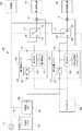
図1を参照して、本開示の第1実施形態に係る蓄電システム100は、第1蓄電ユニット102、第2蓄電ユニット104、コントローラ106、第1切替部108、第2切替部110、第3切替部112、第1センサ114、及び第2センサ116を含む。第1蓄電ユニット102及び第2蓄電ユニット104は、第1切替部108を介して太陽光システム180に接続されている。第1蓄電ユニット102は、第2切替部110を介して第1特定負荷194に接続され、第2蓄電ユニット104は第3切替部112を介して第2特定負荷196に接続されている。蓄電システム100は、電力系統190の停電時に自立運転を行う。(First Embodiment)
[overall structure]
With reference to FIG. 1, the
第1特定負荷194及び第2特定負荷196は、電力系統190に停電が発生していないとき(以下、通常時ともいう)に限らず、電力系統190の停電時にも電力が供給されるべき負荷である。一般負荷192は、通常時に電力が供給されるが、停電時には電力が供給されない負荷である。なお、実際の配電線は複数本(2相又は3相)であるが、図1では1本のラインで示している。 The first
太陽光システム180は、太陽光パネル182及び太陽光PCS184を含む。太陽光パネル182は、光エネルギーを電力に変換することにより発電する電力機器である。太陽光PCS184は、太陽光パネル182により発電された直流電力(直流電圧)を交流電力(交流電圧)に変換して出力する。太陽光PCS184は、通常時には、電力系統190から商用電力を供給する配電線を介して、一般負荷192、第1特定負荷194及び第2特定負荷196に電力を供給する。このとき、第2切替部110においては、端子150及び端子154が接続され、第3切替部112においては、端子160及び端子164が接続されている。太陽光PCS184は、停電時には、商用電力を供給する配電線への電力供給を停止し、自立出力端子186から電力を供給する。停電の発生は、例えば、電力系統190からの電力供給を検出するセンサ(図示せず)の検出値を観測することにより検出可能である。そのセンサの検出値が所定値以下になれば、停電が発生したと判定できる。 The
第1蓄電ユニット102は、第1PCS120及び第1蓄電池122を含む。第1PCS120は、制御部(CPU、マイコン等)と、記憶部(例えば、書換可能な不揮発性メモリ)と、直流電力及び交流電力を相互に変換する変換回路とを含む。第1PCS120は、さらに通信部を含み、コントローラ106の通信部と通信を行う。第1蓄電池122は、リチウムイオン二次電池等の充放電可能な蓄電池である。第1蓄電ユニット102は、補助入力端子124から入力される交流電力を、そのまま出力端子126から出力する。第1PCS120は、コントローラ106からの制御を受けて動作し、第1蓄電池122の蓄電電力(直流電圧)を交流電力(交流電圧)に変換して出力端子126から出力する。また、第1PCS120は、補助入力端子124から入力される交流電力を直流電力に変換して、第1蓄電池122を充電する。 The first
同様に、第2蓄電ユニット104は、第2PCS130及び第2蓄電池132を含む。第2PCS130は、制御部と、記憶部と、直流電力及び交流電力を相互に変換する変換回路とを含む。第2PCS130は、さらに通信部を含み、コントローラ106の通信部と通信を行う。第2蓄電池132は、リチウムイオン二次電池等の充放電可能な蓄電池である。第2蓄電ユニット104は、補助入力端子134から入力される交流電力を、そのまま出力端子136から出力する。第2PCS130は、コントローラ106からの制御を受けて動作し、第2蓄電池132の蓄電電力(直流電圧)を交流電力(交流電圧)に変換して出力端子136から出力する。また、第2PCS130は、補助入力端子134から入力される交流電力を直流電力に変換して、第2蓄電池132を充電する。 Similarly, the second
コントローラ106は、制御部(CPU、マイコン等)と記憶部(例えば、書換可能な不揮発性メモリ)と通信部とを含み、第1切替部108、第2切替部110、第3切替部112、第1PCS120及び第2PCS130を制御する。コントローラ106は、停電時には、第1切替部108、第2切替部110、第3切替部112、第1PCS120及び第2PCS130の各々に対して、後述するように所定の動作を実行させる。 The
第1切替部108において、端子140は太陽光PCS184の自立出力端子186に接続され、端子142は第1蓄電ユニット102の補助入力端子124に接続され、端子144は第2蓄電ユニット104の補助入力端子134に接続されている。第1切替部108は、通常時には端子140を端子142及び端子144のいずれとも接続していないが、停電時にコントローラ106からの制御を受けて、端子140を端子142又は端子144に接続する。第1切替部108は、例えばリレーにより実現される。 In the
第2切替部110において、端子150は、商用電力が供給される配電線に接続され、端子152は、第1蓄電ユニット102の出力端子126に接続され、端子154は、第1特定負荷194に接続されている。第2切替部110は、通常時には、上記したように端子150及び端子154を接続しており、停電時には、コントローラ106の制御を受けて接続状態を変更し、端子152及び端子154を接続する。同様に、第3切替部112において、端子160は、商用電力が供給される配電線に接続され、端子162は、第2蓄電ユニット104の出力端子136に接続され、端子164は、第2特定負荷196に接続されている。第3切替部112は、通常時には、上記したように端子160及び端子164を接続しており、停電時には、コントローラ106の制御を受けて接続状態を変更し、端子162及び端子164を接続する。第2切替部110及び第3切替部112は、例えばリレーにより実現される。 In the
第1センサ114及び第2センサ116は、例えば電流センサであり、設置された位置で電線に流れる電流(交流)を測定し、対応する情報(電流値等)を出力する。第1センサ114は、第1特定負荷194に供給される電流を測定し、測定値は第1PCS120に出力される。同様に、第2センサ116は、第2特定負荷196に供給される電流を測定し、測定値は第2PCS130に出力される。第1PCS120及び第2PCS130は、それぞれ第1センサ114及び第2センサ116の測定値を受けて、第1特定負荷194及び第2特定負荷196に供給されている電力量(消費電力)を求め、後述する処理において利用する。 The
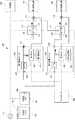
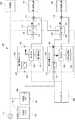
このように構成されることにより、蓄電システム100は、通常時には図1に示したように、太陽光システム180の発電電力を、電力系統190から商用電力を供給する配電線を介して一般負荷192に供給し、第2切替部110を介して第1特定負荷194に供給し、第3切替部112を介して第2特定負荷196に供給する。停電時には蓄電システム100は自立運転を行い、図2を参照して、上記したように、コントローラ106により、第1切替部108、第2切替部110及び第3切替部112における接続状態が変更される。図2は、太陽光システム180の発電電力が第1特定負荷194の消費電力よりも大きい場合を示しており、第1切替部108は、端子140を端子142に接続している。図2において、矢印は電流の流れる方向を示す。上記したように、停電時には太陽光システム180は、商用電力を供給する配電線への発電電力の供給を停止し、発電電力を自立出力端子186から出力するので、太陽光システム180の発電電力は第1蓄電ユニット102を介して第1特定負荷194に供給される。太陽光システム180の発電電力が第1特定負荷194の消費電力よりも大きいので、第1蓄電ユニット102の第1PCS120は、太陽光システム180の余剰電力により第1蓄電池122を充電する。一方、第2特定負荷196には、第2蓄電池132の蓄電電力が第2PCS130により変換された交流電力が、第2蓄電ユニット104の出力端子136から供給される。 With this configuration, the
[制御動作]
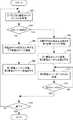
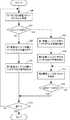
以下に、図3を参照して、電力系統190の停電時における蓄電システム100の動作を説明する。図3のフローチャートはコントローラ106により実行される。具体的には、コントローラ106の制御部は、停電が発生したことを検知すると、第2切替部110及び第3切替部112を停電時の状態に設定して第1特定負荷194及び第2特定負荷196を電力系統190から切り離した後、コントローラ106内部の記憶部から所定のプログラムを読出して実行する。ここでは、太陽光システム180の余剰電力により、第1蓄電ユニット102を第2蓄電ユニット104よりも優先的に充電するものとする。[Control operation]
The operation of the
ステップ300において、コントローラ106は、第1蓄電ユニット102及び第2蓄電ユニット104から、それぞれの内部の第1蓄電池122及び第2蓄電池132の蓄電量(以下、SOC(State Of Charge)という)を取得する。具体的には、コントローラ106は、第1PCS120及び第2PCS130からSOC(%)を取得する。その後、制御はステップ302に移行する。第1蓄電池122及び第2蓄電池132のSOCを、それぞれSOC1(%)及びSOC2(%)で表す。 In
ステップ302において、コントローラ106は、ステップ300で取得したSOC1が100%(第1蓄電池122が満充電)であるか否かを判定する。SOC1が100%であると判定された場合、制御はステップ308に移行し、そうでなければ、制御はステップ304に移行する。 In
ステップ304において、コントローラ106は、太陽光PCS184の自立出力端子186を第1蓄電ユニット102に接続する。即ち、コントローラ106は、上記したように、第1切替部108を制御して端子140及び端子142を接続させる(図2参照)。これにより、第1蓄電ユニット102は、補助入力端子124に入力される太陽光システム180の発電電力を出力端子126から出力する。出力端子126から出力される電力は、第2切替部110を介して第1特定負荷194に供給される。その後、制御はステップ306に移行する。 In
ステップ306において、コントローラ106は、第1蓄電ユニット102に充電を指示し、第2蓄電ユニット104に放電を指示する。即ち、コントローラ106は、第1PCS120に充電を開始させ、第2PCS130に放電を開始させる。これにより、第1PCS120は、太陽光システム180の余剰電力により第1蓄電池122を充電する。余剰電力の有無は、補助入力端子124に入力される電力量が第1特定負荷194に供給される電力量よりも大きいか否かにより判定できる。第1PCS120は、補助入力端子124に入力される電力量を、第1蓄電ユニット102内部の電流センサの検出値から算出し、第1特定負荷194に供給される電力量を、第1センサ114から入力される電流値から算出する。一方、第2蓄電ユニット104の第2PCS130は、第2蓄電池132の蓄電電力を交流に変換して、出力端子136から出力する。出力端子136から出力される電力は、第3切替部112を介して第2特定負荷196に供給される。その後、制御はステップ316に移行する。 In
一方、SOC1が100%であれば、ステップ308において、コントローラ106は、太陽光システム180の自立出力端子186を第2蓄電ユニット104に接続する。即ち、コントローラ106は、第1切替部108を制御して、端子140及び端子144を接続させる。これにより、第2蓄電ユニット104は、補助入力端子134に入力される太陽光システム180の発電電力を出力端子136から出力する。出力端子136から出力される電力は、第3切替部112を介して第2特定負荷196に供給される。その後、制御はステップ310に移行する。 On the other hand, if SOC1 is 100%, in
ステップ310において、コントローラ106は、第1蓄電ユニット102に放電を指示し、第2蓄電ユニット104に充電を指示する。即ち、コントローラ106は、第1PCS120に放電を開始させ、第2PCS130に充電を開始させる。これにより、第1PCS120は、第1蓄電池122の蓄電電力を交流に変換して、出力端子126から出力する。出力端子126から出力される電力は、第2切替部110を介して第1特定負荷194に供給される。一方、第2PCS130は、太陽光システム180の余剰電力により第2蓄電池132を充電する。余剰電力の有無は、補助入力端子134に入力される電力量が第2特定負荷196に供給される電力量よりも大きいか否かにより判定できる。第2PCS130は、補助入力端子134に入力される電力量を、第2蓄電ユニット104内部の電流センサの検出値から算出し、第2特定負荷196に供給される電力量を、第2センサ116から入力される電流値から算出する。その後、制御はステップ312に移行する。 In
ステップ312において、コントローラ106は、第2蓄電ユニット104から内部の第2蓄電池132のSOC(SOC2)を取得する。その後、制御はステップ314に移行する。 In
ステップ314において、コントローラ106は、ステップ312で取得したSOC2が100%(第2蓄電池132が満充電)であるか否かを判定する。SOC2が100%であると判定された場合、制御はステップ316に移行する。そうでなければ、制御はステップ312に戻る。 In
ステップ316において、コントローラ106は、終了するか否かを判定する。例えば、電力系統190の停電が解消し、電力系統190から電力の供給が開始されたことにより、コントローラ106は終了と判定する。終了すると判定された場合、コントローラ106は、第1切替部108、第2切替部110及び第3切替部112を通常時の状態に変更し、第1蓄電ユニット102及び第2蓄電ユニット104に対して停止を指示する。その後、本プログラムは終了する。そうでなければ、制御はステップ300に戻り、終了すると判定されるまで、ステップ300以降の処理が繰返される。 In
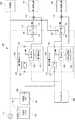
以上により、電力系統190の停電時には、コントローラ106は、第2切替部110及び第3切替部112を制御して第1特定負荷194及び第2特定負荷196を電力系統190から切り離した後、自立出力端子186が補助入力端子124又は補助入力端子134に接続されるように第1切替部108を制御する。そして、コントローラ106は、第1蓄電ユニット102及び第2蓄電ユニット104の各々の内部の蓄電池のSOCに応じて、第1蓄電ユニット102及び第2蓄電ユニット104に充電又は放電を開始させる。コントローラ106は、第1蓄電ユニット102から受信したSOC(SOC1)が100%(第1蓄電池122が満充電)であるか否かを判定して、100%でなければ、図2に示したように、太陽光システム180の余剰電力により第1蓄電池122を充電させる(ステップ306)。その後、第1蓄電ユニット102から受信したSOC(SOC1)が100%になれば、図4に示すように、太陽光システム180の余剰電力により第2蓄電池132を充電させる(ステップ310)。図4においては、自立出力端子186から出力される太陽光システム180の発電電力は、補助入力端子134に入力され、出力端子136から出力される。補助入力端子134から出力される電力は、第3切替部112を介して第2特定負荷196に供給される。第1特定負荷194には、第1蓄電ユニット102の出力端子126から出力される電力(第1蓄電池122の蓄電電力が第1PCS120により変換された交流電力)が、第2切替部110を介して供給される。このように、1つの太陽光システム180により第1蓄電ユニット102及び第2蓄電ユニット104を充電できる。 As described above, in the event of a power failure of the
上記では、第1蓄電ユニット102の第1蓄電池122を、第2蓄電ユニット104の第2蓄電池132よりも優先的に充電する場合を説明したが、これに限定されない。第2蓄電ユニット104の第2蓄電池132を、第1蓄電ユニット102の第1蓄電池122よりも優先的に充電してもよい。 In the above, the case where the
(第1変形例)
上記では、第1蓄電ユニット102及び第2蓄電ユニット104のいずれか一方の蓄電池を優先的に充電する場合を説明したが、第1蓄電ユニット102及び第2蓄電ユニット104の蓄電池の充電制御はこれに限定されない。いずれか一方の蓄電池を優先的に充電する場合には、優先的に充電される蓄電ユニットはSOCが大きい状態で保持される機会が増えることがある。この場合、蓄電池の劣化に繋がることがある。これを防止するには、第1蓄電ユニット102及び第2蓄電ユニット104の蓄電池を均等に充電することが好ましい。本変形例では、第1蓄電ユニット102及び第2蓄電ユニット104のSOC(%)の差(ばらつき)が所定値を超えていれば、SOCがより小さい方の蓄電ユニットに太陽光システム180の発電電力を供給して充電する。差が所定値以下になれば、太陽光システム180の発電電力の供給先を別の蓄電ユニットに切替えて、別の蓄電ユニットを充電するように制御する。具体的には、図5に示すように蓄電システムを制御する。(First modification)
In the above, the case where one of the storage batteries of the first
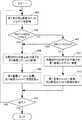
図5を参照して、電力系統190の停電時に、第1蓄電ユニット102及び第2蓄電ユニット104の蓄電池を均等に充電する制御方法に関して説明する。図5のフローチャートはコントローラ106により実行される。具体的には、コントローラ106の制御部は、停電が発生したことを検知すると、第2切替部110及び第3切替部112を停電時の状態に設定して第1特定負荷194及び第2特定負荷196を電力系統190から切り離した後、コントローラ106内部の記憶部から所定のプログラムを読出して実行する。 A control method for evenly charging the storage batteries of the first
ステップ400において、コントローラ106は、第1蓄電ユニット102及び第2蓄電ユニット104から、それぞれの内部の第1蓄電池122及び第2蓄電池132のSOC(%)を取得する。具体的には、コントローラ106は、第1PCS120及び第2PCS130からSOCを取得する。その後、制御はステップ402に移行する。第1蓄電池122及び第2蓄電池132のSOCを、それぞれSOC1(%)及びSOC2(%)で表す。 In
ステップ402において、コントローラ106は、SOC1からSOC2を減算して得られた差(以下、減算値という)が5%より大きいか否かを判定する。減算値が5%より大きいと判定された場合、制御はステップ404に移行し、そうでなければ、制御はステップ408に移行する。 In
ステップ404において、コントローラ106は、太陽光システム180の自立出力端子186を第2蓄電ユニット104に接続する。即ち、コントローラ106は、第1切替部108を制御して、端子140及び端子144を接続させる。これにより、第2蓄電ユニット104は、補助入力端子134に入力される太陽光システム180の発電電力を出力端子136から出力する。出力端子136から出力される電力は、第3切替部112を介して第2特定負荷196に供給される。その後、制御はステップ406に移行する。 In
ステップ406において、コントローラ106は、第1蓄電ユニット102に放電を指示し、第2蓄電ユニット104に充電を指示する。即ち、コントローラ106は、第1PCS120に放電を開始させ、第2PCS130に充電を開始させる。これにより、第1PCS120は、第1蓄電池122の蓄電電力を交流電力に変換して、出力端子126から出力する。出力端子126から出力される交流電力は、第2切替部110を介して第1特定負荷194に供給される。一方、第2PCS130は、太陽光システム180の余剰電力により第2蓄電池132を充電する。その後、制御はステップ414に移行する。 In
SOC1からSOC2を減算した値が5%以下であれば、ステップ408において、コントローラ106は、SOC1が100%(第1蓄電池122が満充電)であるか否かを判定する。SOC1が100%であると判定された場合、制御はステップ404に移行し、そうでなければ、制御はステップ410に移行する。 If the value obtained by subtracting SOC2 from SOC1 is 5% or less, in
ステップ410において、コントローラ106は、太陽光PCS184の自立出力端子186を第1蓄電ユニット102に接続する。即ち、コントローラ106は、上記したように、第1切替部108を制御して端子140及び端子142を接続させる。これにより、第1蓄電ユニット102は、補助入力端子124に入力される太陽光システム180の発電電力を出力端子126から出力する。出力端子126から出力される電力は、第2切替部110を介して第1特定負荷194に供給される。その後、制御はステップ412に移行する。 In
ステップ412において、コントローラ106は、第1蓄電ユニット102に充電を指示し、第2蓄電ユニット104に放電を指示する。即ち、コントローラ106は、第1PCS120に充電を開始させ、第2PCS130に放電を開始させる。これにより、第1蓄電ユニット102の第1PCS120は、太陽光システム180の余剰電力により第1蓄電池122を充電する。一方、第2蓄電ユニット104の第2PCS130は、第2蓄電池132の蓄電電力を交流電力に変換して、出力端子136から出力する。出力端子136から出力される交流電力は、第3切替部112を介して第2特定負荷196に供給される。その後、制御はステップ414に移行する。 In
ステップ414において、コントローラ106は、終了するか否かを判定する。終了すると判定された場合、コントローラ106は、第1切替部108、第2切替部110及び第3切替部112を通常時の状態に変更し、第1蓄電ユニット102及び第2蓄電ユニット104に対して停止指示を送信する。その後、本プログラムは終了する。そうでなければ、制御はステップ400に戻り、終了すると判定されるまで、ステップ400以降の処理が繰返される。 In
以上により、電力系統190の停電時には、コントローラ106は、第2切替部110及び第3切替部112を制御して第1特定負荷194及び第2特定負荷196を電力系統190から切り離した後、自立出力端子186が補助入力端子124又は補助入力端子134に接続されるように第1切替部108を制御する。そして、コントローラ106は、第1蓄電ユニット102及び第2蓄電ユニット104の各々の内部の蓄電池のSOCの差に応じて、第1蓄電ユニット102及び第2蓄電ユニット104に充電又は放電を開始させる。即ち、コントローラ106は、第1蓄電ユニット102及び第2蓄電ユニット104の各々から受信したSOCの減算値(SOC1−SOC2)が5%より大きいか否かを判定し、最初の状態で減算値が5%より大きければ、図4に示したように、太陽光システム180の余剰電力により、蓄電量がより少ない第2蓄電ユニット104の第2蓄電池132を充電させる(ステップ406)。その後、第2蓄電池132の蓄電量が増大して減算値が5%以下になり、第1蓄電ユニット102の第1蓄電池122が満充電でなければ、コントローラ106は、図2に示したように、太陽光システム180の余剰電力により第1蓄電池122を充電させる(ステップ412)。 As described above, in the event of a power failure of the
最初の状態で、減算値が5%以下であり、第1蓄電ユニット102の第1蓄電池122が満充電でなければ、コントローラ106は、図2に示したように、太陽光システム180の余剰電力により第1蓄電池122を充電させる(ステップ412)。その後、第1蓄電池122の蓄電量が増大して減算値が5%よりも大きくなれば、コントローラ106は、図4に示したように、太陽光システム180の余剰電力により第2蓄電池132を充電させる(ステップ406)。 In the initial state, if the subtraction value is 5% or less and the
このように、充電を開始した後、ばらつきを表す減算値と所定値(例えば5%)との大小関係が変化する度に、太陽光システム180の発電電力の供給先を変更することにより、1つの太陽光システム180により、第1蓄電ユニット102及び第2蓄電ユニット104の内部の蓄電池の蓄電量の差が小さくなるように充電できる。即ち、第1蓄電ユニット102及び第2蓄電ユニット104の内部の蓄電池を均等に充電できる。これにより、一方の蓄電ユニットの蓄電池のみの劣化が進むことを防止できる。 In this way, by changing the supply destination of the generated power of the
(第2実施形態)
[全体構成]
第1実施形態(図1参照)では、蓄電システム100が、第1蓄電ユニット102及び第2蓄電ユニット104の外部に設けた第1切替部108を含む場合を説明したが、これに限定されない。本開示の第2実施形態では、第1切替部108の機能を代替するスイッチを、2つの蓄電ユニットのそれぞれの内部に含む。図6を参照して、本開示の第2実施形態に係る蓄電システム200は、図1の蓄電システム100において、第1切替部108を削除し、第1蓄電ユニット102、第2蓄電ユニット104及びコントローラ106のそれぞれを第1蓄電ユニット202、第2蓄電ユニット204及びコントローラ206で代替したものである。図6において、図1と同じ符号を付した要素は、蓄電システム100と同じ機能を有するので、重複説明を省略し、主として異なる点に関して説明する。(Second Embodiment)
[overall structure]
In the first embodiment (see FIG. 1), the case where the
第1蓄電ユニット202は、第1PCS120、第1蓄電池122及び第1内部スイッチ208を含む。第1PCS120は、制御部と、記憶部と、直流電力及び交流電力を相互に変換する変換回路とを含む。第1PCS120は、さらに通信部を含み、コントローラ206の通信部と通信を行う。第1蓄電ユニット202は、補助入力端子124から入力される交流電力を、そのまま出力端子126から出力する。第1PCS120は、コントローラ206からの制御を受けて動作し、第1蓄電池122の蓄電電力(直流電圧)を交流電力(交流電圧)に変換して出力端子126から出力し、補助入力端子124から入力される交流電力を直流電力に変換して、第1蓄電池122を充電する。また、第1PCS120は、第1内部スイッチ208のON/OFFを制御する。 The first
同様に、第2蓄電ユニット204は、第2PCS130、第2蓄電池132及び第2内部スイッチ210を含む。第2PCS130は、制御部と、記憶部と、直流電力及び交流電力を相互に変換する変換回路とを含む。第2PCS130は、さらに通信部を含み、コントローラ206の通信部と通信を行う。第2蓄電ユニット204は、補助入力端子134から入力される交流電力を、そのまま出力端子136から出力する。第2PCS130は、コントローラ206からの制御を受けて動作し、第2蓄電池132の蓄電電力(直流電圧)を交流電力(交流電圧)に変換して出力端子136から出力し、補助入力端子134から入力される交流電力を直流電力に変換して、第2蓄電池132を充電する。また、第2PCS130は、第2内部スイッチ210のON/OFFを制御する。 Similarly, the second
コントローラ206は、制御部と記憶部と通信部とを含み、第2切替部110、第3切替部112、第1PCS120及び第2PCS130を制御する。コントローラ206は、停電時には、第2切替部110、第3切替部112、第1PCS120及び第2PCS130の各々に対して、後述するように所定の動作を実行させる。 The
このように構成されることにより、蓄電システム200は、通常時には図6に示したように、太陽光システム180の発電電力を、電力系統190から商用電力を供給する配電線を介して一般負荷192に供給し、第2切替部110を介して第1特定負荷194に供給し、第3切替部112を介して第2特定負荷196に供給する。図7を参照して、停電時には蓄電システム200において、上記したように、コントローラ206により、第2切替部110及び第3切替部112における接続状態が変更される。図7は、太陽光システム180の発電電力が第1特定負荷194の消費電力よりも大きい場合を示している。図7において、矢印は電流を示す。上記したように、停電時には太陽光システム180は、商用電力を供給する配電線への発電電力の供給を停止し、発電電力を自立出力端子186から出力するので、太陽光システム180の発電電力は第1蓄電ユニット202を介して第1特定負荷194に供給される。太陽光システム180の発電電力が第1特定負荷194の消費電力よりも大きいので、第1蓄電ユニット202の第1PCS120は、太陽光システム180の余剰電力により第1蓄電池122を充電する。一方、第2特定負荷196には、第2蓄電池132の蓄電電力が第2PCS130により変換された交流電力が、第2蓄電ユニット204の出力端子136から供給される。 With this configuration, the
[制御動作]
以下に、図8を参照して、電力系統190の停電時における蓄電システム200の動作を説明する。図8のフローチャートはコントローラ206により実行される。具体的には、コントローラ206の制御部は、停電が発生したことを検知すると、第2切替部110及び第3切替部112を停電時の状態に設定して第1特定負荷194及び第2特定負荷196を電力系統190から切り離した後、コントローラ206内部の記憶部から所定のプログラムを読出して実行する。ここでは、太陽光システム180の余剰電力により、第1蓄電ユニット202を第2蓄電ユニット204よりも優先的に充電するものとする。[Control operation]
The operation of the
図8のフローチャートは、図3のフローチャートにおいて、ステップ304、306、308及び310がそれぞれステップ320、322、324及び326で代替されたものである。図8において、図3と同じ符号を付したステップの処理は、図3のステップの処理と同じである。但し、主体はコントローラ106からコントローラ206に変更され、第1蓄電ユニット102及び第2蓄電ユニット104はそれぞれ第1蓄電ユニット202及び第2蓄電ユニット204に代替されている。ここでは、重複説明を省略し、主として異なる点に関して説明する。 In the flowchart of FIG. 8,
コントローラ206は、第1蓄電ユニット202及び第2蓄電ユニット204から各々のSOC(SOC1及びSOC2)を取得し(ステップ300)、SOC1が100%であるか否かを判定する(ステップ302)。ステップ302において、100%でないと判定された場合、ステップ320において、コントローラ206は、第1蓄電ユニット202(第1PCS120)に、第1内部スイッチ208をONに設定すること、及び充電を指示する。これにより、第1PCS120は、第1内部スイッチ208をONに設定し、太陽光システム180の余剰電力により第1蓄電池122を充電する。その後、制御はステップ322に移行する。第1内部スイッチ208がONであれば、補助入力端子124に入力される太陽光システム180の発電電力は、出力端子126から出力され、第2切替部110を介して第1特定負荷194に供給される。 The
ステップ322において、コントローラ206は、第2蓄電ユニット204(第2PCS130)に、第2内部スイッチ210をOFFに設定すること、及び放電を指示する。これにより、第2PCS130は、第2内部スイッチ210をOFFに設定し、放電を開始する。その後、制御はステップ316に移行する。第2内部スイッチ210がOFFであれば、補助入力端子134に入力される太陽光システム180の発電電力は、出力端子136から出力されることはない。出力端子136からは、第2PCS130が第2蓄電池132の電力を変換した交流電力が出力され、第3切替部112を介して第2特定負荷196に供給される。 In
一方、ステップ302において、SOC1が100%であると判定された場合、ステップ324において、コントローラ206は、第1蓄電ユニット202(第1PCS120)に、第1内部スイッチ208をOFFし、放電を指示する。これにより、第1PCS120は、第1内部スイッチ208をOFFし、放電を開始する。その後、制御はステップ326に移行する。第1内部スイッチ208がOFFであれば、補助入力端子124に入力される太陽光システム180の発電電力は、出力端子126から出力されることはない。出力端子126からは、第1PCS120が第1蓄電池122の電力を変換した交流電力が出力され、第2切替部110を介して第1特定負荷194に供給される。 On the other hand, when it is determined in
ステップ326において、コントローラ206は、第2蓄電ユニット204(第2PCS130)に、第2内部スイッチ210をONに設定すること、及び充電を指示する。これにより、第2PCS130は、第2内部スイッチ210をONに設定し、太陽光システム180の余剰電力により第2蓄電池132を充電する。その後、制御はステップ316に移行する。第2内部スイッチ210がONであれば、補助入力端子134に入力される太陽光システム180の発電電力は、出力端子136から出力され、第3切替部112を介して第2特定負荷196に供給される。 In
ステップ316において、コントローラ206は、終了するか否かを判定し、終了すると判定されるまで、ステップ300以降の処理が繰返される。 In
以上により、電力系統190の停電時には、コントローラ206は、第2切替部110及び第3切替部112を制御して第1特定負荷194及び第2特定負荷196を電力系統190から切り離す。そして、コントローラ206は、第1蓄電ユニット202及び第2蓄電ユニット204の各々の内部の蓄電池のSOCに応じて、第1蓄電ユニット202及び第2蓄電ユニット204に、各々の内部スイッチの設定と、充電又は放電の開始を指示する。コントローラ206は、第1蓄電ユニット202から受信したSOC(SOC1)が100%(第1蓄電池122が満充電)であるか否かを判定して、100%でなければ、図7に示したように、太陽光システム180の余剰電力により第1蓄電池122を充電させる(ステップ320)。その後、第1蓄電ユニット202から受信したSOC(SOC1)が100%になれば、図9に示すように、太陽光システム180の余剰電力により第2蓄電池132を充電させる(ステップ326)。図9においては、自立出力端子186から出力される太陽光システム180の発電電力は、補助入力端子134に入力され、出力端子136から出力される。出力端子136から出力される電力は、第3切替部112を介して第2特定負荷196に供給される。第1特定負荷194には、第1蓄電ユニット202の出力端子126から出力される電力が、第2切替部110を介して供給される。このように、1つの太陽光システム180により第1蓄電ユニット202及び第2蓄電ユニット204を充電できる。 As described above, in the event of a power failure of the
また、各蓄電ユニットに内部スイッチを設けることにより、蓄電ユニットの外部に切替部(図1の第1切替部108)を設ける場合よりも、蓄電ユニットの増設が容易である。なお、上記では、第1蓄電ユニット202の第1蓄電池122を、第2蓄電ユニット204の第2蓄電池132よりも優先的に充電する場合を説明したが、これに限定されない。第2蓄電ユニット204の第2蓄電池132を、第1蓄電ユニット202の第1蓄電池122よりも優先的に充電してもよい。 Further, by providing the internal switch in each power storage unit, it is easier to add the power storage unit than in the case where the switching unit (
(第2変形例)
上記では、第1蓄電ユニット202及び第2蓄電ユニット204のいずれか一方の蓄電池を優先的に充電する場合を説明したが、第1蓄電ユニット202及び第2蓄電ユニット204の蓄電池の充電制御はこれに限定されない。上記したように、いずれか一方の蓄電ユニットの蓄電池のみの劣化が進むことを防止するために、図6の蓄電システム200において、第1蓄電ユニット202及び第2蓄電ユニット204の蓄電池を均等に充電してもよい。(Second modification)
In the above, the case where one of the storage batteries of the first
図10を参照して、電力系統190の停電時に、第1蓄電ユニット202及び第2蓄電ユニット204の蓄電池を均等に充電する制御方法に関して説明する。図10のフローチャートはコントローラ206により実行される。具体的には、コントローラ206の制御部は、停電が発生したことを検知すると、第2切替部110及び第3切替部112を停電時の状態に設定して第1特定負荷194及び第2特定負荷196を電力系統190から切り離した後、コントローラ206内部の記憶部から所定のプログラムを読出して実行する。 With reference to FIG. 10, a control method for evenly charging the storage batteries of the first
図10のフローチャートは、図5のフローチャートにおいて、ステップ404、406、410及び412がそれぞれステップ420、422、424及び426で代替されたものである。図10において、図5と同じ符号を付したステップの処理は、図5のステップの処理と同じである。但し、主体はコントローラ106からコントローラ206に変更され、第1蓄電ユニット102及び第2蓄電ユニット104がそれぞれ第1蓄電ユニット202及び第2蓄電ユニット204に代替されている。ここでは、重複説明を省略し、主として異なる点に関して説明する。 In the flowchart of FIG. 10,
コントローラ206は、第1蓄電ユニット202及び第2蓄電ユニット204から各々のSOC(SOC1及びSOC2)を取得し(ステップ400)、SOC1からSOC2を減算して得られた値(減算値)が5%より大きいか否かを判定する(ステップ402)。ステップ402において、減算値が5%より大きいと判定された場合、ステップ420において、コントローラ206は、第1蓄電ユニット202(第1PCS120)に、第1内部スイッチ208をOFFし、放電を指示する。これにより、第1PCS120は、第1内部スイッチ208をOFFし、放電を開始する。その後、制御はステップ422に移行する。第1内部スイッチ208がOFFであれば、補助入力端子124に入力される太陽光システム180の発電電力は、出力端子126から出力されることはない。出力端子126からは、第1PCS120が第1蓄電池122の電力を変換した交流電力が出力され、第2切替部110を介して第1特定負荷194に供給される。 The
ステップ422において、コントローラ206は、第2蓄電ユニット204(第2PCS130)に、第2内部スイッチ210をONに設定すること、及び充電を指示する。これにより、第2PCS130は、第2内部スイッチ210をONに設定し、太陽光システム180の余剰電力により第2蓄電池132を充電する。その後、制御はステップ414に移行する。第2内部スイッチ210がONであれば、補助入力端子134に入力される太陽光システム180の発電電力は、出力端子136から出力され、第3切替部112を介して第2特定負荷196に供給される。 In
ステップ402において減算値が5%以下であると判定されても、ステップ408において第1蓄電ユニット202のSOC(SOC1)が100%であると判定された場合には、ステップ420及び422が実行される。 Even if it is determined in
一方、ステップ402において、減算値が5%以下であると判定され、且つ、ステップ408において第1蓄電ユニット202のSOC(SOC1)が100%でないと判定された場合には、ステップ424において、コントローラ206は、第1蓄電ユニット202(第1PCS120)に、第1内部スイッチ208をONに設定すること、及び充電を指示する。これにより、第1PCS120は、第1内部スイッチ208をONに設定し、太陽光システム180の余剰電力により第1蓄電池122を充電する。その後、制御はステップ426に移行する。第1内部スイッチ208がONであれば、補助入力端子124に入力される太陽光システム180の発電電力は、出力端子126から出力され、第2切替部110を介して第1特定負荷194に供給される。 On the other hand, if it is determined in
ステップ426において、コントローラ206は、第2蓄電ユニット204(第2PCS130)に、第2内部スイッチ210をOFFに設定すること、及び放電を指示する。これにより、第2PCS130は、第2内部スイッチ210をOFFに設定し、放電を開始する。その後、制御はステップ414に移行する。第2内部スイッチ210がOFFであれば、補助入力端子134に入力される太陽光システム180の発電電力は、出力端子136から出力されることはない。出力端子136からは、第2PCS130が第2蓄電池132の電力を変換した交流電力が出力され、第3切替部112を介して第2特定負荷196に供給される。 In
ステップ414において、コントローラ206は、終了するか否かを判定し、終了すると判定されるまで、ステップ400以降の処理が繰返される。 In
以上により、電力系統190の停電時には、コントローラ206は、第2切替部110及び第3切替部112を制御して第1特定負荷194及び第2特定負荷196を電力系統190から切り離す。そして、コントローラ206は、第1蓄電ユニット202及び第2蓄電ユニット204の各々の内部の蓄電池のSOCの差に応じて、第1蓄電ユニット202及び第2蓄電ユニット204に充電又は放電を開始させる。即ち、コントローラ206は、第1蓄電ユニット202及び第2蓄電ユニット204の各々から受信したSOCの減算値(SOC1−SOC2)が5%より大きいか否かを判定し、減算値が5%より大きければ、図9に示したように、太陽光システム180の余剰電力により第2蓄電池132を充電させる(ステップ422)。減算値が5%以下であれば、コントローラ206は、図7に示したように、太陽光システム180の余剰電力により第1蓄電池122を充電させる(ステップ424)。 As described above, in the event of a power failure of the
したがって、上記の第1変形例と同様に、充電を開始した後、ばらつきを表す減算値と所定値(例えば5%)との大小関係が変化する度に、太陽光システム180の発電電力の供給先を変更することにより、1つの太陽光システム180により、第1蓄電ユニット202及び第2蓄電ユニット204の内部の蓄電池を均等に充電できる。これにより、一方の蓄電ユニットの蓄電池のみの劣化が進むことを防止できる。 Therefore, as in the first modification described above, the power generated by the
(第3変形例)
蓄電システム200において、太陽光システム180の発電電力が減少し、発電電力の現在の供給先である特定負荷(例えば第1特定負荷194)の消費電力よりも小さくなれば、発電電力を特定負荷に供給できなくなる。その場合には、その特定負荷に接続されている蓄電システム(第1蓄電ユニット202)は、内部スイッチ(第1内部スイッチ208)をOFFにし、放電によりその特定負荷に電力を供給する。その後、その蓄電ユニット(第1蓄電ユニット202)は、コントローラ206から充電が指示されたままであるので、太陽光システム180の発電量を知るために(余剰電力の有無を判定するために)、内部スイッチ(第1内部スイッチ208)をONにする。依然として太陽光システム180の発電量が特定負荷(第1特定負荷194)の消費電力よりも小さければ、対応する蓄電ユニット(第1蓄電ユニット202)は、内部スイッチ(第1内部スイッチ208)を再度OFFにする。即ち、太陽光システム180及び蓄電ユニットの接続が維持され、コントローラ206からその蓄電ユニットに対する充電の指示が維持されていれば、その蓄電ユニットの内部スイッチのON/OFFが繰返される問題がある。(Third modification example)
In the
このとき、他方の特定負荷(第2特定負荷196)には、他方の蓄電システム(第2蓄電ユニット204)の放電により電力が供給されている。しかし、太陽光システム180の発電電力が、電力供給先の特定負荷(第1特定負荷194)の消費電力よりも小さくても、他方の特定負荷(第2特定負荷196)の消費電力よりも大きければ、太陽光システム180の発電電力を他方の特定負荷に供給できる。 At this time, power is supplied to the other specific load (second specific load 196) by discharging the other power storage system (second power storage unit 204). However, even if the generated power of the
したがって、本変形例では、上記事項を考慮して、図11に示すような制御を行う。なお、第1特定負荷194の消費電力は第2特定負荷196の消費電力よりも大きいとする。図11のフローチャートは、図8のフローチャートにおいて、ステップ340、342、344及び346が追加されたものである。図11において、図8と同じ符号を付したステップの処理は、図8のステップの処理と同じである。したがって、重複説明を省略し、主として異なる点に関して説明する。 Therefore, in this modification, the control as shown in FIG. 11 is performed in consideration of the above items. It is assumed that the power consumption of the first
コントローラ206は、第1蓄電ユニット202及び第2蓄電ユニット204から各々のSOC(SOC1及びSOC2)を取得し(ステップ300)、SOC1が100%であるか否かを判定する(ステップ302)。ステップ302において、100%でないと判定された場合、コントローラ206は、ステップ320及び322を実行する。これにより、第1内部スイッチ208がON、第2内部スイッチ210がOFFとなり、第1蓄電ユニット202は、入力される太陽光システム180の発電電力を第1特定負荷194に供給し、太陽光システム180の余剰電力により第1蓄電池122を充電する。一方、第2蓄電ユニット204は、放電により第2特定負荷196に電力を供給する。 The
続いて、ステップ340において、コントローラ206は、太陽光システム180の発電電力が第1特定負荷194の消費電力よりも小さいか否かを判定する。具体的には、コントローラ206は、太陽光システム180の発電電力及び第1特定負荷194の消費電力を第1PCS120から取得して判定する。第1PCS120は、上記したように、第1蓄電池122を充電するために、太陽光システム180の余剰電力の有無を判定するので、太陽光システム180の発電電力及び第1特定負荷194の消費電力をコントローラ206に提供できる。太陽光システム180の発電電力が第1特定負荷194の消費電力よりも小さいと判定された場合、制御はステップ324に移行する。そうでなければ、制御はステップ316に移行する。 Subsequently, in
一方、ステップ302において、SOC1が100%であると判定された場合、コントローラ206は、ステップ324及び326を実行する。これにより、第1内部スイッチ208がOFF、第2内部スイッチ210がONとなり、第1蓄電ユニット202は、放電により第1特定負荷194に電力を供給する。一方、第2蓄電ユニット204は、入力される太陽光システム180の発電電力を第2特定負荷196に供給し、太陽光システム180の余剰電力により第2蓄電池132を充電する。 On the other hand, if it is determined in
続いて、ステップ342において、コントローラ206は、太陽光システム180の発電電力が第2特定負荷196の消費電力よりも小さいか否かを判定する。具体的には、コントローラ206は、太陽光システム180の発電電力及び第2特定負荷196の消費電力を第2PCS130から取得して判定する。第2PCS130は、上記したように、第2蓄電池132を充電するために、太陽光システム180の余剰電力の有無を判定するので、太陽光システム180の発電電力及び第2特定負荷196の消費電力をコントローラ206に提供できる。太陽光システム180の発電電力が第2特定負荷196の消費電力よりも小さいと判定された場合、制御はステップ344に移行する。そうでなければ、制御はステップ312に移行する。 Subsequently, in
ステップ344において、コントローラ206は、第2蓄電ユニット204(第2PCS130)に、第2内部スイッチ210をOFFに設定すること、及び放電を指示する。これにより、第2PCS130は、第2内部スイッチ210をOFFに設定し、放電を開始する。その後、制御はステップ346に移行する。第2内部スイッチ210がOFFであれば、補助入力端子134に入力される太陽光システム180の発電電力は、出力端子136から出力されることはない。出力端子136からは、第2PCS130が第2蓄電池132の電力を変換した交流電力が出力され、第3切替部112を介して第2特定負荷196に供給される。なお、このとき、第1蓄電ユニット202は、放電により第1特定負荷194に電力を供給している状態を維持している(ステップ324)。 In
ステップ346において、コントローラ206は、太陽光システム180の発電電力が第2特定負荷196の消費電力以上か否かを判定する。具体的には、コントローラ206は、ステップ342と同様に、太陽光システム180の発電電力及び第2特定負荷196の消費電力を第2PCS130から取得して判定する。太陽光システム180の発電電力が第2特定負荷196の消費電力以上であると判定された場合、制御はステップ316に移行する。そうでなければ、制御はステップ344に戻る。 In
ステップ316において、コントローラ206は、終了するか否かを判定し、終了すると判定されるまで、ステップ300以降の処理が繰返される。 In
以上により、電力系統190の停電時には、コントローラ206は、第2切替部110及び第3切替部112を制御して第1特定負荷194及び第2特定負荷196を電力系統190から切り離す。そして、コントローラ206は、第1蓄電ユニット202及び第2蓄電ユニット204の各々の内部の蓄電池のSOCに応じて、第1蓄電ユニット202及び第2蓄電ユニット204に、各々の内部スイッチの設定と、充電又は放電の開始を指示する。コントローラ206は、第1蓄電ユニット202から受信したSOC(SOC1)が100%(第1蓄電池122が満充電)であるか否かを判定して、100%でなければ、図7に示したように、太陽光システム180の余剰電力により第1蓄電池122を充電させる(ステップ320)。その後、第1蓄電ユニット202から受信したSOC(SOC1)が100%になれば、図9に示したように、太陽光システム180の余剰電力により第2蓄電池132を充電させる(ステップ326)。 As described above, in the event of a power failure of the
図7に示したように、SOC1が100%未満であり、太陽光システム180の余剰電力により第1蓄電池122を充電している状態で、太陽光システム180の発電電力が低下して第1特定負荷194の消費電力よりも小さくなることが考えられる(ステップ340の判定結果がYES)。その場合には、図9に示したように、第1内部スイッチ208がOFFされ、第1蓄電ユニット202は放電により第1特定負荷194に電力を供給し(ステップ324)、第2内部スイッチ210がONされ、第2蓄電ユニット204は太陽光システム180の余剰電力により第2蓄電池132を充電する(ステップ326)。 As shown in FIG. 7, in a state where the SOC1 is less than 100% and the
図9の状態において、太陽光システム180の発電電力がさらに低下して第2特定負荷196の消費電力よりも小さくなることが考えられる(ステップ342の判定結果がYES)。その場合には、図12に示すように、第2内部スイッチ210がOFFされ、第2蓄電ユニット204は放電により第2特定負荷196に電力を供給する(ステップ344)。第1内部スイッチ208はOFFされたままであり、第1蓄電ユニット202は放電により第1特定負荷194に電力を供給している(ステップ324)。 In the state of FIG. 9, it is conceivable that the generated power of the
図12の状態において、太陽光システム180の発電電力が増大して第2特定負荷196の消費電力以上になることが考えられる(ステップ346の判定結果がYES)。その場合には、図7又は図9に示した状態に戻る。即ち、SOC1が100%であるか否か(ステップ302)、及び、太陽光システム180の発電量が第1特定負荷194の消費電力より小さいか否か(ステップ340)により、上記したように、第1蓄電ユニット202を太陽光システム180の余剰電力で充電する(図7参照)、又は、第2蓄電ユニット204を太陽光システム180の余剰電力で充電する(図9参照)。 In the state of FIG. 12, it is conceivable that the generated power of the
したがって、太陽光システム180の発電電力が、電力供給先の特定負荷(第1特定負荷194)の消費電力よりも小さくなった場合に、蓄電ユニット(第1蓄電ユニット202)の内部スイッチ(第1内部スイッチ208)がON/OFFを繰返すことを防止できる。また、太陽光システム180の発電電力が、電力供給先の特定負荷(第1特定負荷194)の消費電力よりも小さくなっても、他方の特定負荷(第2特定負荷196)の消費電力よりも大きければ、太陽光システム180の発電電力を他方の特定負荷に供給でき、太陽光システム180の余剰電力により、他方の特定負荷に対応する蓄電システム(第2蓄電ユニット204)を充電できる。したがって、太陽光システム180の発電電力を無駄にすることなく、有効に利用できる。 Therefore, when the generated power of the
なお、図11は、第1特定負荷194の消費電力が第2特定負荷196の消費電力よりも大きい場合のフローチャートであるが、第2特定負荷196の消費電力が第1特定負荷194の消費電力よりも大きい場合には、図11において、第1蓄電ユニット202及び第2蓄電ユニット204を交換すればよい。 Note that FIG. 11 is a flowchart in which the power consumption of the first
(第4変形例)
図10に示したフローチャートに関しても、図11と同様に、ステップ340、342、344及び346を追加できる。即ち、コントローラ206は、図13に示す制御を実行できる。(Fourth modification)
With respect to the flowchart shown in FIG. 10,
図13は、図10のフローチャートにおいて、ステップ426(図11のステップ322に対応)の次に、ステップ340が追加され、ステップ422(図11のステップ326に対応)の次にステップ342、344及び346が追加されたものである。したがって、図13のフローチャートによっても、図11のフローチャートと同様に、太陽光システム180の発電電力の低下に応じて、蓄電システム200を図7の状態から図9の状態に変化させ、さらに図9の状態から図11の状態に変化させることができる。また、太陽光システム180の発電電力が増大すれば、蓄電システム200を図11の状態から図7又は図9の状態に変化させることができる。したがって、蓄電ユニット内部の内部スイッチがON/OFFを繰返すことを防止でき、太陽光システム180の発電電力を無駄にすることなく、有効に利用できる。 FIG. 13 shows in the flowchart of FIG. 10, step 426 (corresponding to step 322 of FIG. 11) is followed by
上記では、蓄電システム200において、太陽光システム180の発電電力が特定負荷の消費電力よりも小さくなった場合の処理に関して説明したが、蓄電システム100においても同様の処理を実行でき、同様の効果を奏し得る。例えば、図3及び図5に示したフローチャートにおいて、それぞれ図11及び図13と同様に、ステップ340、342、344及び346を追加すればよい。 In the above, the processing when the generated power of the
上記では、SOCが100%であるか否かを判定したが、これに限定されない。蓄電ユニット内部の蓄電池が所定量以上蓄電されているか否か(例えば、満充電に近い状態か否か)を判定できればよい。例えば、100%以下80%以上の範囲の値であってもよい。 In the above, it is determined whether or not the SOC is 100%, but the present invention is not limited to this. It suffices if it can be determined whether or not the storage battery inside the power storage unit is stored in a predetermined amount or more (for example, whether or not the state is close to full charge). For example, the value may be in the range of 100% or less and 80% or more.
また、2つの蓄電ユニットを均等に充電する制御(図5、図10及び図13)において、2つの蓄電ユニットのいずれを充電するかを判定する基準値を5%としたが、これに限定されない。2つの蓄電ユニットの蓄電量ができるだけ均等になるように充電できるように、判定の基準値を設定すればよい。例えば、0%より大きく20%以下の範囲の値であってもよい。判定の基準値が小さいと、第1切替部108を頻繁に切替えることになるので、第1切替部108(例えば、リレー)の切替回数の寿命を考慮して、判定の基準値を適切な値に設定することが好ましい。 Further, in the control for evenly charging the two power storage units (FIGS. 5, 10 and 13), the reference value for determining which of the two power storage units is to be charged is set to 5%, but the present invention is not limited to this. .. The reference value for determination may be set so that the two storage units can be charged so that the amount of electricity stored is as equal as possible. For example, the value may be in the range of more than 0% and 20% or less. If the reference value for determination is small, the
また、上記では、2つの蓄電ユニットのいずれを充電するかを判定するのに、2つの蓄電ユニットのSOCの差(減算値)を用いる場合を説明したがこれに限定されない。2つの蓄電ユニットの各々のSOCから算出される、蓄電量の違いの程度を表す変数(SOC1及びSOC2の関数)であればよい。例えば、SOC1とSOC2との比率(SOC1/SOC2)を使用してもよい。判定の基準値は、判定に使用する変数に応じて設定すればよい。例えば、SOC1/SOC2を使用する場合、上記の5%に対応する基準値として1.05を使用すればよい。 Further, in the above description, the case where the difference (subtraction value) of the SOCs of the two power storage units is used to determine which of the two power storage units is to be charged is not limited thereto. Any variable (function of SOC1 and SOC2) that represents the degree of difference in the amount of electricity stored, which is calculated from the SOC of each of the two electricity storage units, may be used. For example, the ratio of SOC1 to SOC2 (SOC1 / SOC2) may be used. The reference value for determination may be set according to the variables used for determination. For example, when SOC1 / SOC2 is used, 1.05 may be used as a reference value corresponding to the above 5%.
上記では、蓄電ユニットが2つである場合を説明したが、これに限定されない。3つ以上の蓄電ユニットを、1つの太陽光システムで充電してもよい。その場合、例えば、複数の蓄電ユニットに予め優先順位を設定し、優先順位の高いものから順に所定の蓄電量(例えば満充電)になるように1つずつ、太陽光システムの発電電力を供給して充電すればよい。1つの太陽光システムに限定されず、太陽光システムの数は、蓄電システムの設置数よりも少なければよい。 In the above, the case where there are two power storage units has been described, but the present invention is not limited to this. Three or more power storage units may be charged by one solar system. In that case, for example, priorities are set in advance for a plurality of power storage units, and the generated power of the solar system is supplied one by one so as to reach a predetermined storage amount (for example, fully charged) in order from the one with the highest priority. And charge it. The number of solar systems is not limited to one, and the number of solar systems may be smaller than the number of power storage systems installed.
また、複数の蓄電ユニットの蓄電量のばらつきを表す変数の値が所定範囲内になるように、蓄電量のより小さい蓄電ユニットから順に1つずつ、太陽光システムの発電電力を供給して充電してもよい。例えば、蓄電量が最小の蓄電ユニットから充電し、その蓄電ユニットの蓄電量が最小でなくなれば、蓄電量が最小になった別の蓄電ユニットを充電することを繰返し、ばらつきを表す変数の値が所定範囲内になるようにする。その後、ばらつきを表す変数の値が、再度所定範囲を超えた場合、充電する蓄電ユニットを変更する。その後、ばらつきを表す変数の値が、再度所定範囲内になった場合にも、充電する蓄電ユニットを変更する。 In addition, the power generated by the solar system is supplied and charged one by one in order from the storage unit with the smallest storage amount so that the value of the variable representing the variation in the storage amount of the plurality of storage units is within the predetermined range. You may. For example, charging is performed from the storage unit having the minimum storage amount, and when the storage amount of the storage unit is not the minimum, another storage unit having the minimum storage amount is repeatedly charged, and the value of the variable representing the variation is set. Keep within the specified range. After that, when the value of the variable representing the variation exceeds the predetermined range again, the power storage unit to be charged is changed. After that, even when the value of the variable representing the variation falls within the predetermined range again, the power storage unit to be charged is changed.
上記では、太陽光システムから供給される交流電力により複数の蓄電ユニットを充電する場合を説明したが、これに限定されない。交流電源であればよく、太陽光システム以外の発電システムから供給される交流電力により複数の蓄電ユニットを充電してもよい。 In the above, the case where a plurality of power storage units are charged by the AC power supplied from the solar system has been described, but the present invention is not limited to this. Any AC power source may be used, and a plurality of power storage units may be charged by AC power supplied from a power generation system other than the solar system.
以上、実施の形態を説明することにより本発明を説明したが、上記した実施の形態は例示であって、本発明は上記した実施の形態のみに制限されるわけではない。本発明の範囲は、発明の詳細な説明の記載を参酌した上で、特許請求の範囲の各請求項によって示され、そこに記載された文言と均等の意味及び範囲内での全ての変更を含む。 Although the present invention has been described above by explaining the embodiments, the above-described embodiments are examples, and the present invention is not limited to the above-described embodiments. The scope of the present invention is indicated by each claim of the scope of claims, taking into consideration the description of the detailed description of the invention, and all changes within the meaning and scope equivalent to the wording described therein. Including.
100、200 蓄電システム
102、202 第1蓄電ユニット
104、204 第2蓄電ユニット
106、206 コントローラ
108 第1切替部
110 第2切替部
112 第3切替部
114 第1センサ
116 第2センサ
120 第1PCS
122 第1蓄電池
124、134 補助入力端子
126、136 出力端子
130 第2PCS
132 第2蓄電池
140、142、144、150、152、154、160、162、164 端子
180 太陽光システム
182 太陽光パネル
184 太陽光PCS
186 自立出力端子
190 電力系統
192 一般負荷
194 第1特定負荷
196 第2特定負荷
208 第1内部スイッチ
210 第2内部スイッチ
300、302、304、306、308、310、312、314、316、320、322、324、326、340、342、344、346、400、402、404、406、408、410、412、414、420、422、424、426 ステップ100, 200
122
132
186
Claims (7)
Translated fromJapanese前記交流電源の出力電力が前記複数の蓄電ユニットのうちのいずれか1つの蓄電ユニットに供給されるように、前記出力電力の供給先を切替える切替部と、
前記蓄電ユニットの自立運転時に前記切替部を制御する制御部とを含み、
前記複数の蓄電ユニットの各々の蓄電ユニットは、
入力される電力を出力する電路と、
前記電路に接続される蓄電池と、
直流電力及び交流電力を相互に変換する変換部とを含み、
前記蓄電ユニットは、前記切替部によって切替えられる前記出力電力の供給先に応じて、自立運転時に、
入力される前記交流電源の前記出力電力を、当該蓄電ユニットの前記電路を介して当該蓄電ユニットに対応する特定負荷に供給し、
入力される前記交流電源の前記出力電力の余剰電力により、当該蓄電ユニットの前記変換部を介して当該蓄電ユニットの前記蓄電池を充電し、
前記交流電源の前記出力電力が入力されなければ、当該蓄電ユニットの前記蓄電池の電力を、当該蓄電ユニットの前記変換部及び前記電路を介して前記特定負荷に供給する、蓄電システム。A power storage system that includes multiple power storage units connected to an AC power supply.
A switching unit that switches the supply destination of the output power so that the output power of the AC power supply is supplied to any one of the plurality of power storage units.
Including a control unit that controls the switching unit during independent operation of the power storage unit.
Each power storage unit of the plurality of power storage units
An electric circuit that outputs the input power and
The storage battery connected to the electric circuit and
Includes a converter that converts DC and AC power to each other
During self-sustaining operation, the power storage unit may be operated independently according to the output power supply destination switched by the switching unit.
The output power of the AC power supply to be input is supplied to a specific load corresponding to the power storage unit via the electric circuit of the power storage unit.
The surplus power of the output power of the AC power source to be input is used to charge the storage battery of the power storage unit via the conversion unit of the power storage unit.
A power storage system that supplies the power of the storage battery of the power storage unit to the specific load via the conversion unit and the electric circuit of the power storage unit if the output power of the AC power source is not input.
前記判定部により前記1つの蓄電ユニットの蓄電量が前記所定値に達したと判定されたことを受けて、前記制御部は、前記切替部に、前記出力電力の供給先を、前記複数の蓄電ユニットのうち、前記1つの蓄電ユニットとは異なる蓄電ユニットに切替えさせる、請求項1又は請求項2に記載の蓄電システム。Further including a determination unit for determining whether or not the amount of electricity stored in the one electricity storage unit has reached a predetermined value in a state where the output power is supplied to one of the plurality of electricity storage units.
In response to the determination by the determination unit that the amount of electricity stored in the one electricity storage unit has reached the predetermined value, the control unit causes the switching unit to supply the output power to the plurality of electricity storage units. The power storage system according to claim 1 or 2, wherein the unit is switched to a power storage unit different from the one power storage unit.
前記判定部により、前記変数の値が前記所定値よりも大きい状態から、前記変数の値が前記所定値以下の状態に変化したと判定されたこと、又は、前記変数の値が前記所定値以下の状態から、前記変数の値が前記所定値よりも大きい状態に変化したと判定されたことを受けて、前記制御部は、前記切替部に、前記出力電力の供給先を、前記複数の蓄電ユニットのうち、前記1つの蓄電ユニットとは異なる蓄電ユニットに切替えさせる、請求項1又は請求項2に記載の蓄電システム。In a state where the output power is supplied to one of the plurality of storage units, the magnitude relationship between the value of the variable representing the variation in the storage amount of each of the plurality of storage units and the predetermined value is determined. Including the judgment part
It is determined by the determination unit that the value of the variable has changed from a state in which the value of the variable is larger than the predetermined value to a state in which the value of the variable is equal to or less than the predetermined value, or the value of the variable is equal to or less than the predetermined value. In response to the determination that the value of the variable has changed from the state of (1) to a state in which the value of the variable is larger than the predetermined value, the control unit causes the switching unit to supply the output power to the plurality of storage destinations. The power storage system according to claim 1 or 2, wherein the unit is switched to a power storage unit different from the one power storage unit.
前記太陽光システムは、
太陽光パネルと、
前記太陽光パネルにより発電された直流電力を交流電力に変換して前記出力電力として出力する電力変換部とを含む、請求項1から請求項5のいずれか1項に記載の蓄電システム。The AC power source is a solar system.
The solar system
With solar panels
The power storage system according to any one of claims 1 to 5, which includes a power conversion unit that converts DC power generated by the solar panel into AC power and outputs it as the output power.
前記蓄電ユニットの自立運転時に前記切替部を制御する第1ステップと、
前記自立運転時に、前記複数の蓄電ユニットの各々の蓄電ユニットを制御する第2ステップとを含み、
前記第2ステップは、前記切替部によって切替えられる前記出力電力の供給先に応じて、前記蓄電ユニットに、
入力される前記交流電源の前記出力電力を、当該蓄電ユニットの前記電路を介して当該蓄電ユニットに対応する特定負荷に供給させるステップと、
入力される前記交流電源の前記出力電力の余剰電力により、当該蓄電ユニットの前記変換部を介して当該蓄電ユニットの前記蓄電池を充電させるステップと、
前記交流電源の前記出力電力が入力されなければ、当該蓄電ユニットの前記蓄電池の電力を、当該蓄電ユニットの前記変換部及び前記電路を介して前記特定負荷に供給させるステップとを含む、制御方法。A switching unit that switches the supply destination of the output power so that the plurality of power storage units connected to the AC power supply and the output power of the AC power supply are supplied to any one of the plurality of power storage units. Each of the power storage units of the plurality of power storage units includes an electric power for outputting input power, a storage battery connected to the electric power, and a conversion unit for mutually converting DC power and AC power. , A control method for power storage systems
The first step of controlling the switching unit during the independent operation of the power storage unit, and
Including the second step of controlling each power storage unit of the plurality of power storage units during the self-sustaining operation.
The second step is performed on the power storage unit according to the supply destination of the output power switched by the switching unit.
A step of supplying the output power of the AC power supply to a specific load corresponding to the power storage unit via the electric circuit of the power storage unit.
A step of charging the storage battery of the power storage unit via the conversion unit of the power storage unit by the surplus power of the output power of the AC power supply that is input.
A control method including a step of supplying the power of the storage battery of the power storage unit to the specific load via the conversion unit of the power storage unit and the electric circuit when the output power of the AC power source is not input.
Priority Applications (1)
| Application Number | Priority Date | Filing Date | Title |
|---|---|---|---|
| JP2019146949AJP7310427B2 (en) | 2019-08-09 | 2019-08-09 | Electricity storage system and its control method |
Applications Claiming Priority (1)
| Application Number | Priority Date | Filing Date | Title |
|---|---|---|---|
| JP2019146949AJP7310427B2 (en) | 2019-08-09 | 2019-08-09 | Electricity storage system and its control method |
Publications (2)
| Publication Number | Publication Date |
|---|---|
| JP2021027783Atrue JP2021027783A (en) | 2021-02-22 |
| JP7310427B2 JP7310427B2 (en) | 2023-07-19 |
Family
ID=74664122
Family Applications (1)
| Application Number | Title | Priority Date | Filing Date |
|---|---|---|---|
| JP2019146949AActiveJP7310427B2 (en) | 2019-08-09 | 2019-08-09 | Electricity storage system and its control method |
Country Status (1)
| Country | Link |
|---|---|
| JP (1) | JP7310427B2 (en) |
Citations (7)
| Publication number | Priority date | Publication date | Assignee | Title |
|---|---|---|---|---|
| JP2008148443A (en)* | 2006-12-08 | 2008-06-26 | Daiwa House Ind Co Ltd | Natural energy utilizing power generation system equipped with power storage section |
| JP2010119225A (en)* | 2008-11-13 | 2010-05-27 | Sumitomo Forestry Home Engineering Co Ltd | Utilization system of generated power |
| JP2013172563A (en)* | 2012-02-21 | 2013-09-02 | Toshiba Corp | Secondary battery charging/discharging system, charger, and charge control method |
| JP2013172619A (en)* | 2012-02-22 | 2013-09-02 | Daiwa House Industry Co Ltd | Power supply system |
| JP2015053854A (en)* | 2011-09-28 | 2015-03-19 | 京セラ株式会社 | Power conditioner system and power-storage power conditioner |
| JP2015159631A (en)* | 2014-02-21 | 2015-09-03 | 株式会社東芝 | Power storage system, control device and control method for power storage system |
| JP2015204656A (en)* | 2014-04-11 | 2015-11-16 | パナソニックIpマネジメント株式会社 | Power supply control device and power supply control method |
- 2019
- 2019-08-09JPJP2019146949Apatent/JP7310427B2/enactiveActive
Patent Citations (7)
| Publication number | Priority date | Publication date | Assignee | Title |
|---|---|---|---|---|
| JP2008148443A (en)* | 2006-12-08 | 2008-06-26 | Daiwa House Ind Co Ltd | Natural energy utilizing power generation system equipped with power storage section |
| JP2010119225A (en)* | 2008-11-13 | 2010-05-27 | Sumitomo Forestry Home Engineering Co Ltd | Utilization system of generated power |
| JP2015053854A (en)* | 2011-09-28 | 2015-03-19 | 京セラ株式会社 | Power conditioner system and power-storage power conditioner |
| JP2013172563A (en)* | 2012-02-21 | 2013-09-02 | Toshiba Corp | Secondary battery charging/discharging system, charger, and charge control method |
| JP2013172619A (en)* | 2012-02-22 | 2013-09-02 | Daiwa House Industry Co Ltd | Power supply system |
| JP2015159631A (en)* | 2014-02-21 | 2015-09-03 | 株式会社東芝 | Power storage system, control device and control method for power storage system |
| JP2015204656A (en)* | 2014-04-11 | 2015-11-16 | パナソニックIpマネジメント株式会社 | Power supply control device and power supply control method |
Also Published As
| Publication number | Publication date |
|---|---|
| JP7310427B2 (en) | 2023-07-19 |
Similar Documents
| Publication | Publication Date | Title |
|---|---|---|
| JP5633478B2 (en) | Storage battery | |
| US11791501B2 (en) | Direct current power supplying system | |
| US9231440B2 (en) | Power supply apparatus and controlling method of the same | |
| CN106487097B (en) | Energy storage equipment for AC voltage network | |
| US10069307B2 (en) | Power conversion device, power conversion system, and power conversion method | |
| CN110176788B (en) | Power storage system and power storage device | |
| EP2822138A1 (en) | Control device, control system, and storage cell control method | |
| JP2015106962A (en) | Charge discharge controller and charge discharge system | |
| US20140176079A1 (en) | Battery system | |
| JP7126243B2 (en) | power supply system | |
| CN104662764A (en) | Power supply system | |
| JP7248023B2 (en) | Power storage system for independent operation, power storage unit, and control method | |
| WO2014083788A1 (en) | Bidirectional converter | |
| US20210167604A1 (en) | Grid interconnection system | |
| JP5507946B2 (en) | Battery control unit | |
| JP2012253842A (en) | Power supply system | |
| JP7310427B2 (en) | Electricity storage system and its control method | |
| US11418051B2 (en) | Direct current power supplying system | |
| JP2013135482A (en) | Charge/discharge controller | |
| CN109923750B (en) | energy storage device | |
| JP7314707B2 (en) | Electricity storage system and its control method | |
| JP7754129B2 (en) | power supply | |
| JP6629694B2 (en) | POWER CONTROL DEVICE AND ITS CONTROL METHOD | |
| JP7661953B2 (en) | Energy Storage System | |
| JP2024154613A (en) | Power Supplies |
Legal Events
| Date | Code | Title | Description |
|---|---|---|---|
| A621 | Written request for application examination | Free format text:JAPANESE INTERMEDIATE CODE: A621 Effective date:20220221 | |
| A977 | Report on retrieval | Free format text:JAPANESE INTERMEDIATE CODE: A971007 Effective date:20221109 | |
| A131 | Notification of reasons for refusal | Free format text:JAPANESE INTERMEDIATE CODE: A131 Effective date:20230110 | |
| A521 | Request for written amendment filed | Free format text:JAPANESE INTERMEDIATE CODE: A523 Effective date:20230302 | |
| A131 | Notification of reasons for refusal | Free format text:JAPANESE INTERMEDIATE CODE: A131 Effective date:20230328 | |
| A521 | Request for written amendment filed | Free format text:JAPANESE INTERMEDIATE CODE: A523 Effective date:20230523 | |
| TRDD | Decision of grant or rejection written | ||
| A01 | Written decision to grant a patent or to grant a registration (utility model) | Free format text:JAPANESE INTERMEDIATE CODE: A01 Effective date:20230606 | |
| A61 | First payment of annual fees (during grant procedure) | Free format text:JAPANESE INTERMEDIATE CODE: A61 Effective date:20230619 | |
| R150 | Certificate of patent or registration of utility model | Ref document number:7310427 Country of ref document:JP Free format text:JAPANESE INTERMEDIATE CODE: R150 |