JP2021027697A - vehicle - Google Patents
vehicleDownload PDFInfo
- Publication number
- JP2021027697A JP2021027697AJP2019143923AJP2019143923AJP2021027697AJP 2021027697 AJP2021027697 AJP 2021027697AJP 2019143923 AJP2019143923 AJP 2019143923AJP 2019143923 AJP2019143923 AJP 2019143923AJP 2021027697 AJP2021027697 AJP 2021027697A
- Authority
- JP
- Japan
- Prior art keywords
- power
- server
- charging
- amount
- ecu
- Prior art date
- Legal status (The legal status is an assumption and is not a legal conclusion. Google has not performed a legal analysis and makes no representation as to the accuracy of the status listed.)
- Pending
Links
Images


Classifications
- Y—GENERAL TAGGING OF NEW TECHNOLOGICAL DEVELOPMENTS; GENERAL TAGGING OF CROSS-SECTIONAL TECHNOLOGIES SPANNING OVER SEVERAL SECTIONS OF THE IPC; TECHNICAL SUBJECTS COVERED BY FORMER USPC CROSS-REFERENCE ART COLLECTIONS [XRACs] AND DIGESTS
- Y02—TECHNOLOGIES OR APPLICATIONS FOR MITIGATION OR ADAPTATION AGAINST CLIMATE CHANGE
- Y02E—REDUCTION OF GREENHOUSE GAS [GHG] EMISSIONS, RELATED TO ENERGY GENERATION, TRANSMISSION OR DISTRIBUTION
- Y02E60/00—Enabling technologies; Technologies with a potential or indirect contribution to GHG emissions mitigation
- Y02E60/10—Energy storage using batteries
- Y—GENERAL TAGGING OF NEW TECHNOLOGICAL DEVELOPMENTS; GENERAL TAGGING OF CROSS-SECTIONAL TECHNOLOGIES SPANNING OVER SEVERAL SECTIONS OF THE IPC; TECHNICAL SUBJECTS COVERED BY FORMER USPC CROSS-REFERENCE ART COLLECTIONS [XRACs] AND DIGESTS
- Y02—TECHNOLOGIES OR APPLICATIONS FOR MITIGATION OR ADAPTATION AGAINST CLIMATE CHANGE
- Y02T—CLIMATE CHANGE MITIGATION TECHNOLOGIES RELATED TO TRANSPORTATION
- Y02T90/00—Enabling technologies or technologies with a potential or indirect contribution to GHG emissions mitigation
- Y02T90/10—Technologies relating to charging of electric vehicles
- Y02T90/16—Information or communication technologies improving the operation of electric vehicles
- Y02T90/167—Systems integrating technologies related to power network operation and communication or information technologies for supporting the interoperability of electric or hybrid vehicles, i.e. smartgrids as interface for battery charging of electric vehicles [EV] or hybrid vehicles [HEV]
- Y—GENERAL TAGGING OF NEW TECHNOLOGICAL DEVELOPMENTS; GENERAL TAGGING OF CROSS-SECTIONAL TECHNOLOGIES SPANNING OVER SEVERAL SECTIONS OF THE IPC; TECHNICAL SUBJECTS COVERED BY FORMER USPC CROSS-REFERENCE ART COLLECTIONS [XRACs] AND DIGESTS
- Y04—INFORMATION OR COMMUNICATION TECHNOLOGIES HAVING AN IMPACT ON OTHER TECHNOLOGY AREAS
- Y04S—SYSTEMS INTEGRATING TECHNOLOGIES RELATED TO POWER NETWORK OPERATION, COMMUNICATION OR INFORMATION TECHNOLOGIES FOR IMPROVING THE ELECTRICAL POWER GENERATION, TRANSMISSION, DISTRIBUTION, MANAGEMENT OR USAGE, i.e. SMART GRIDS
- Y04S10/00—Systems supporting electrical power generation, transmission or distribution
- Y04S10/12—Monitoring or controlling equipment for energy generation units, e.g. distributed energy generation [DER] or load-side generation
- Y04S10/126—Monitoring or controlling equipment for energy generation units, e.g. distributed energy generation [DER] or load-side generation the energy generation units being or involving electric vehicles [EV] or hybrid vehicles [HEV], i.e. power aggregation of EV or HEV, vehicle to grid arrangements [V2G]
- Y—GENERAL TAGGING OF NEW TECHNOLOGICAL DEVELOPMENTS; GENERAL TAGGING OF CROSS-SECTIONAL TECHNOLOGIES SPANNING OVER SEVERAL SECTIONS OF THE IPC; TECHNICAL SUBJECTS COVERED BY FORMER USPC CROSS-REFERENCE ART COLLECTIONS [XRACs] AND DIGESTS
- Y04—INFORMATION OR COMMUNICATION TECHNOLOGIES HAVING AN IMPACT ON OTHER TECHNOLOGY AREAS
- Y04S—SYSTEMS INTEGRATING TECHNOLOGIES RELATED TO POWER NETWORK OPERATION, COMMUNICATION OR INFORMATION TECHNOLOGIES FOR IMPROVING THE ELECTRICAL POWER GENERATION, TRANSMISSION, DISTRIBUTION, MANAGEMENT OR USAGE, i.e. SMART GRIDS
- Y04S30/00—Systems supporting specific end-user applications in the sector of transportation
- Y04S30/10—Systems supporting the interoperability of electric or hybrid vehicles
- Y04S30/12—Remote or cooperative charging
- Y—GENERAL TAGGING OF NEW TECHNOLOGICAL DEVELOPMENTS; GENERAL TAGGING OF CROSS-SECTIONAL TECHNOLOGIES SPANNING OVER SEVERAL SECTIONS OF THE IPC; TECHNICAL SUBJECTS COVERED BY FORMER USPC CROSS-REFERENCE ART COLLECTIONS [XRACs] AND DIGESTS
- Y04—INFORMATION OR COMMUNICATION TECHNOLOGIES HAVING AN IMPACT ON OTHER TECHNOLOGY AREAS
- Y04S—SYSTEMS INTEGRATING TECHNOLOGIES RELATED TO POWER NETWORK OPERATION, COMMUNICATION OR INFORMATION TECHNOLOGIES FOR IMPROVING THE ELECTRICAL POWER GENERATION, TRANSMISSION, DISTRIBUTION, MANAGEMENT OR USAGE, i.e. SMART GRIDS
- Y04S30/00—Systems supporting specific end-user applications in the sector of transportation
- Y04S30/10—Systems supporting the interoperability of electric or hybrid vehicles
- Y04S30/14—Details associated with the interoperability, e.g. vehicle recognition, authentication, identification or billing
Landscapes
- Charge And Discharge Circuits For Batteries Or The Like (AREA)
- Secondary Cells (AREA)
- Electric Propulsion And Braking For Vehicles (AREA)
- Remote Monitoring And Control Of Power-Distribution Networks (AREA)
- Supply And Distribution Of Alternating Current (AREA)
Abstract
Translated fromJapaneseDescription
Translated fromJapanese本開示は、電力平準化の要請に従って外部の電力網との間で電力の授受が可能な蓄電装置を搭載した車両に関する。 The present disclosure relates to a vehicle equipped with a power storage device capable of transmitting and receiving electric power to and from an external electric power grid in accordance with a request for electric power leveling.
従来、工場あるいは住宅に駐車する電動車両に搭載された蓄電装置などの小規模のエネルギーリソースをサーバ等を用いて遠隔・統合制御することであたかも一つの発電所のように機能するバーチャルパワープラント(以下、VPPと記載する)が公知である。このようなVPPにおいては、たとえば、電動車両に搭載された蓄電装置の充放電を行なうことにより電力網における電力の需要量を変化させて電力需要の平準化が可能になる。 Conventionally, a virtual power plant that functions as if it were a single power plant by remotely and integratedly controlling small-scale energy resources such as power storage devices mounted on electric vehicles parked in factories or houses using servers and the like. Hereinafter referred to as VPP) is known. In such a VPP, for example, by charging / discharging a power storage device mounted on an electric vehicle, it is possible to change the amount of power demand in the power grid and level the power demand.
電力の需要量の変化の要請に対して参加した電動車両のユーザにはその変化の貢献分に相当するインセンティブが与えられる。この貢献分を精度高く取得するため、たとえば、電力網と電動車両との間で授受される電力量を精度高く検出することが求められる。特開2013−240242号公報(特許文献1)には、車外の充電設備側で計測される電力量と、電動車両において計測される電力量とを比較して異常の有無を判断する技術が開示される。 Users of electric vehicles who participate in a request for a change in the amount of electricity demand are given an incentive corresponding to the contribution of the change. In order to acquire this contribution with high accuracy, for example, it is required to accurately detect the amount of electric power transferred between the power grid and the electric vehicle. Japanese Unexamined Patent Publication No. 2013-240242 (Patent Document 1) discloses a technique for determining the presence or absence of an abnormality by comparing the amount of electric power measured on the charging equipment side outside the vehicle with the amount of electric power measured on the electric vehicle. Will be done.
しかしながら、たとえば、複数の電動車両が同じ充電設備に接続され、並行して充電が行なわれる場合においては、各電動車両に供給される電力量を精度高く取得することができない場合がある。特許文献1においては、同じ充電設備に複数の電動車両が接続される場合について考慮されておらず、上述の問題を解決することができない。 However, for example, when a plurality of electric vehicles are connected to the same charging facility and charged in parallel, it may not be possible to accurately obtain the amount of electric power supplied to each electric vehicle. Patent Document 1 does not consider the case where a plurality of electric vehicles are connected to the same charging equipment, and cannot solve the above-mentioned problem.
本開示は、上述した課題を解決するためになされたものであって、その目的は、電力平準化の要請に従って外部の電力網と授受される電力量を精度高く取得可能な車両を提供することである。 The present disclosure has been made to solve the above-mentioned problems, and an object thereof is to provide a vehicle capable of accurately acquiring the amount of electric power to be transferred to and from an external electric power grid in accordance with a request for electric power leveling. is there.
本開示のある局面に係る車両は、蓄電装置と、車両の外部の電力網と蓄電装置との間で授受される授受電力を検出する検出装置と、電力平準化の要請に従って蓄電装置において授受される授受電力量を管理する、車両の外部に設けられる管理装置との間で、通信可能に構成される通信装置と、管理装置に所定の情報を送信するように通信装置を制御する制御装置とを備える。制御装置は、要請に従って電力網と蓄電装置との間で電力が授受される場合に、検出装置を用いて授受電力を検出し、検出された授受電力を積算して算出される授受電力量についての情報を通信装置を用いて管理装置に送信する。 The vehicle according to a certain aspect of the present disclosure is transferred to and from the power storage device, a detection device that detects the power exchanged between the power network outside the vehicle and the power storage device, and the power storage device in accordance with the request for power leveling. A communication device configured to be able to communicate with a management device provided outside the vehicle that manages the amount of power exchanged and received, and a control device that controls the communication device so as to transmit predetermined information to the management device. Be prepared. When power is transferred between the power grid and the power storage device according to the request, the control device detects the transmitted / received power using the detection device, and integrates the detected transferred / received power to calculate the transferred power amount. Information is transmitted to the management device using a communication device.
このようにすると、電力平準化の要請に従って電力網と蓄電装置との間で電力が授受される場合に、検出装置を用いて授受電力が検出され、検出された授受電力が積算されて授受電力量が算出される。算出された授受電力量についての情報は、通信装置を用いて管理装置に送信されるため、管理装置において車両における授受電力量を精度高く取得することができる。 In this way, when power is transferred between the power grid and the power storage device in accordance with the request for power leveling, the transmitted / received power is detected using the detection device, and the detected transfer power is integrated and the transferred power amount. Is calculated. Since the calculated information about the transferred power amount is transmitted to the management device using the communication device, the managed device can acquire the transferred power amount in the vehicle with high accuracy.
本開示によると、電力平準化の要請に従って外部の電力網と授受される電力量を精度高く取得可能な車両を提供することができる。 According to the present disclosure, it is possible to provide a vehicle capable of accurately acquiring the amount of electric power exchanged with an external electric power grid in accordance with a request for electric power leveling.
以下、本開示の実施の形態について、図面を参照しながら詳細に説明する。なお、図中同一または相当部分には同一符号を付してその説明は繰り返さない。 Hereinafter, embodiments of the present disclosure will be described in detail with reference to the drawings. The same or corresponding parts in the drawings are designated by the same reference numerals, and the description thereof will not be repeated.
図1は、本開示の実施の形態に係る車両を含むVGI(Vehicle Grid Integration)システム1の構成の一例を示す図である。図1を参照して、VGIシステム1は、電力会社E1と、上位アグリゲータE2と、下位アグリゲータE3とを含む。 FIG. 1 is a diagram showing an example of a configuration of a VGI (Vehicle Grid Integration) system 1 including a vehicle according to an embodiment of the present disclosure. With reference to FIG. 1, the VGI system 1 includes a power company E1, an upper aggregator E2, and a lower aggregator E3.
電力会社E1は、発電および電力の供給を行なう。電力会社E1は、サーバ10と、発電所11と、送配電設備12と、スマートメータ13とを含む。 The electric power company E1 generates and supplies electric power. The electric power company E1 includes a
発電所11は、電気を発生させるための発電装置を備え、発電装置によって生成された電力を送配電設備12に供給するように構成される。送配電設備12は、送電線、変電所、および配電線を含み、発電所11から供給される電力の送電および配電を行なうように構成される。発電所11および送配電設備12によって電力系統(電力網)が構築されている。 The
スマートメータ13は、所定時間経過ごとに電力使用量を計測し、計測した電力使用量を記憶するとともにサーバ10へ送信するように構成される。 The
上位アグリゲータE2に属する各事業者(以下、「親AG」とも称する)は、下位アグリゲータE3に属する複数の事業者(以下、「子AG」とも称する)を管理し、管轄内の子AGが制御した電力量を束ねることによってエネルギーマネジメントサービスを提供する。 Each business operator belonging to the upper aggregator E2 (hereinafter, also referred to as "parent AG") manages a plurality of businesses belonging to the lower aggregator E3 (hereinafter, also referred to as "child AG"), and is controlled by the child AG in the jurisdiction. We provide energy management services by bundling the amount of electricity generated.
サーバ10は、管轄内の複数の親AG(たとえば、サーバ10に登録された親AG)の情報を管理するように構成される。上位アグリゲータE2は、親AGごとに設けられた複数のサーバ(たとえば、サーバ20A〜20C)を含む。以下、区別して説明する場合を除いて、上位アグリゲータE2に含まれる各サーバを「サーバ20」と記載する。図1には、一例として3個のサーバ20(サーバ20A〜20C)が示されている。 The
上位アグリゲータE2に含まれる各サーバ20は、管轄内の複数の子AG(たとえば、サーバ20に登録された子AG)の情報を管理するように構成される。下位アグリゲータE3に属する各事業者(子AG)は、DR信号(デマンドレスポンス信号)によって各需要家に電力平準化(すなわち、電力需要の抑制または増加)を要請することにより電力量を制御する。下位アグリゲータE3は、子AGごとに設けられた複数のサーバ(たとえば、サーバ30A〜30C)を含む。以下、区別して説明する場合を除いて、下位アグリゲータE3に含まれる各サーバを「サーバ30」と記載する。図1に示すサーバ30A〜30Cは、共通のサーバ20(たとえば、サーバ20B)によって管理される。図1には、一例として3個のサーバ30(サーバ30A〜30C)が示されている。 Each
図1に示すVGIシステム1において子AG(ひいては、サーバ30)が管理する需要家は、EV(電気自動車)である。EVは、EVSE(車両用給電設備)から電力の供給を受けることができる。この実施の形態において、VGIシステム1は、たとえば、住宅内に設置されたAC方式(交流電力供給方式)のEVSE(たとえば、普通充電器)を含む。なお、VGIシステム1は、AC方式のEVSEと、DC方式(直流電力供給方式)のEVSE(たとえば、急速充電器)とのうちの少なくともいずれかを含んでいればよい。また、EVSEは、たとえば、HEMS−GW(Home Energy Management System−GateWay)によって管理される。 In the VGI system 1 shown in FIG. 1, the consumer managed by the child AG (and thus the server 30) is an EV (electric vehicle). The EV can be supplied with electric power from an EVSE (Vehicle Power Supply Facility). In this embodiment, the VGI system 1 includes, for example, an AC (AC power supply) EVSE (eg, a normal charger) installed in a house. The VGI system 1 may include at least one of an AC type EVSE and a DC type (DC power supply type) EVSE (for example, a quick charger). The EVSE is managed by, for example, HEMS-GW (Home Energy Management System-GateWay).
VGIシステム1は、EVSE、EV、およびHEMS−GWの各々を複数含む(図1には、各々1つのみ図示)。以下、区別して説明する場合を除いて、VGIシステム1に含まれる各EVSE、各EV、各HEMS−GWを、それぞれ「EVSE40」、「EV50」、「HEMS−GW60」と記載する。 The VGI system 1 includes a plurality of each of EVSE, EV, and HEMS-GW (only one of each is shown in FIG. 1). Hereinafter, each EVSE, each EV, and each HEMS-GW included in the VGI system 1 will be described as "EVSE40", "EV50", and "HEMS-GW60", respectively, except when they are described separately.
下位アグリゲータE3に含まれる各サーバ30は、管轄内の複数のEV50(たとえば、サーバ30に登録されたEV)の情報を管理するように構成される。EV50を識別するための識別情報(以下、「車両ID」とも称する)がEV50ごとに付与されている。サーバ30は、EV50ごとの情報を車両IDで区別して管理している。また、下位アグリゲータE3に含まれる各サーバ30は、管轄内の各HEMS−GW60(たとえば、サーバ30に登録されたHEMS−GW)と通信可能に構成され、管轄内のEVSE40(たとえば、サーバ30に登録されたEVSE)の状態をHEMS−GW60から取得するように構成される。HEMS−GW60は、サーバ30から情報(たとえば、後述するDR信号)を受信するとともに、EVSE40の状態をサーバ30へ送信するように構成される。 Each
EVSE40は、スマートメータ13を介して電力会社E1の電力系統に接続されている。EVSE40における電力使用量(たとえば、EVの充電に使用した電力量)は、スマートメータ13によって計測され、サーバ10へ送信される。スマートメータ13は、VGIシステム1に含まれるEVSE40ごとに設けられている。VGIシステム1に含まれる各EVSE40は、電力会社E1によって管理されるとともに、電力会社E1から電力の供給を受けている。 The EVSE 40 is connected to the power system of the electric power company E1 via the
以下、図2を用いて、VGIシステム1を構成する各要素の機能について説明する。図2は、VGIシステム1の通信系統図である。図2において、EV50AおよびEV50Bの各々は、前述したEV50(図1)の一例に相当する。ただし、EV50Aは、たとえば、EVSE40が設置された住宅の駐車スペースに駐車した状態で、充電ケーブルを介してEVSE40と電気的に接続されている。一方、EV50Bは走行中である。 Hereinafter, the functions of the elements constituting the VGI system 1 will be described with reference to FIG. FIG. 2 is a communication system diagram of the VGI system 1. In FIG. 2, each of EV50A and EV50B corresponds to the above-mentioned example of EV50 (FIG. 1). However, the EV50A is electrically connected to the EVSE40 via a charging cable, for example, in a state of being parked in a parking space of a house in which the EVSE40 is installed. On the other hand, EV50B is running.
図2を参照して、VGIシステム1では、サーバ10とサーバ20との間、および、サーバ20とサーバ30との間は、いずれも所定の通信方式で相互通信可能に構成される。 With reference to FIG. 2, in the VGI system 1, the
サーバ30は、EV50BおよびHEMS−GW60の各々と通信可能に構成される。サーバ30とHEMS−GW60とは、たとえばインターネットを介して相互に通信するように構成される。サーバ30と各EV50(すなわち、EV50AおよびEV50B)とは、たとえば、相互に無線通信するように構成される。 The
HEMS−GW60とEVSE40とは、たとえば、有線または無線のLAN(Local Area Network)を介して相互通信するように構成される。EVSE40とEV50Aとは、たとえば充電ケーブルを介してCAN(Controller Area Network)またはPLC(Power Line Communication)などの通信方式で相互通信するように構成される。 The HEMS-
VGIシステム1は、データセンタ70と、データセンタ70に登録された携帯端末80とをさらに含む。 The VGI system 1 further includes a
データセンタ70は、たとえばインターネットを介してサーバ30と通信するように構成される。データセンタ70は、登録された複数の携帯端末80の情報(たとえば、端末IDやユーザが所有する車両の車両IDなどの情報)を管理するように構成される。携帯端末80は、たとえば、ユーザごとに携帯され、タッチパネルディスプレイを具備するスマートフォン等を含む。 The
携帯端末80には所定のアプリケーションソフトウェアを通じてHEMS−GW60およびデータセンタ70の各々と情報のやり取りが可能に構成される。携帯端末80は、たとえばインターネットを介してHEMS−GW60およびデータセンタ70の各々と無線通信が可能に構成される。 The
サーバ10は、DR(デマンドレスポンス)を利用して電力の需給バランスを調整するように構成される。サーバ10が、こうした調整を行なうときには、まず、上位アグリゲータE2に含まれる各サーバ20(たとえば、図1に示すサーバ20A〜20C)に対してDRへの参加を要請するDR信号(以下、「DR要請」とも称する)を送信する。DR要請には、当該DRの対象となる地域、DRの種類(たとえば、下げDRまたは上げDR)、およびDR期間が含まれる。 The
電力会社E1は、たとえば、電力の需要を増やしたいときに、上げDRへの参加を要請するDR要請をサーバ10から各サーバ20へ送信する。たとえば、電力の需要量が、日中に多くなり、深夜に少なくなるような変化を示す傾向がある場合、電力会社E1は、深夜の時間帯に上げDRへの参加を上位アグリゲータE2に要請することにより、深夜の電力需要量を増やして、電力需要の負荷平準化を図ることができる。 For example, when the electric power company E1 wants to increase the demand for electric power, the electric power company E1 transmits a DR request requesting participation in the raised DR from the
サーバ20は、サーバ10からDR要請を受信したときに、DR可能量(すなわち、DRに従って調整可能な電力量)を求めてサーバ10へ送信するように構成される。サーバ20は、たとえば管轄内の各子AGのDR容量(すなわち、DR対応可能な容量)の合計に基づいてDR可能量を求めることができる。サーバ20は、たとえばサーバ30に問い合わせることによって管轄内の各子AGのDR容量を取得することができる。サーバ10は、上位アグリゲータE2に含まれる各サーバ20から受信したDR可能量に基づいて親AGごとのDR量(すなわち、親AGに依頼する電力調整量)を決定し、各親AGのサーバ20にDR実行を指示する信号(以下、「第1DR実行指示」とも称する)を送信する。第1DR実行指示には、当該DRの対象となる地域、DRの種類(たとえば、下げDRまたは上げDR)、親AGごとのDR量、およびDR期間が含まれる。 When the
サーバ30は、管轄内の各EV50の状態を示す情報(たとえば、車両の位置、バッテリ残量、走行スケジュールおよび走行条件)を各EV50から逐次取得し、保存するように構成される。こうしたデータが蓄積されることによって、管轄内の各EV50の充電履歴および走行履歴がサーバ30に保存されることになる。また、サーバ30は、管轄内の各EVSE40の状態を示す情報(たとえば、充電中であるか否かを示す情報、充電スケジュール、充電条件)を、各EVSE40に接続される各HEMS−GW60から逐次取得し、保存するように構成される。こうしたデータが蓄積されることによって、管轄内の各EVSE40の充電履歴がサーバ30に保存されることになる。 The
サーバ30は、サーバ20から前述の問合せがあった場合に、上述したEV50、EVSE40、およびユーザの各々に関する情報に基づいて当該サーバ30に対応する子AGのDR容量を求めて、そのDR容量をサーバ20へ送信するように構成される。サーバ20は、サーバ10から前述の第1DR実行指示を受信すると、下位アグリゲータE3に含まれる各サーバ30から受信したDR容量に基づいて子AGごとのDR量(すなわち、子AGに調整を依頼する電力量)を決定し、各子AGのサーバ30にDR実行を指示する信号(以下、「第2DR実行指示」とも称する)を送信する。第2DR実行指示には、当該DRの対象となる地域、DRの種類(たとえば、下げDRまたは上げDR)、子AGごとのDR量、およびDR期間が含まれる。 When the
サーバ30は、第2DR実行指示を受信すると、管轄内のEV50のうちDR対応可能な各EV50に対してDR量の割当てを行ない、EV50ごとのDR信号を作成するとともに各EV50にDR信号を送信する。DR信号には、DRの種類(たとえば、下げDRまたは上げDR)、EV50ごとのDR量、およびDR期間が含まれる。 When the
図3は、EV50の構成の一例を示す図である。図3を参照して、EV50は、MG(Motor Generator)51と、動力伝達ギア52と、駆動輪53と、PCU(Power Control Unit54と、SMR(System Main Relay)55と、充電リレー57と、充電装置56と、インレット59と、バッテリ110と、ECU(Electronic Control Unit)200と、通信装置210とを備える。ECU200は、充電装置56を用いてEV50の充電制御を行なうように構成される。 FIG. 3 is a diagram showing an example of the configuration of EV50. With reference to FIG. 3, the
バッテリ110は、走行用の電力を蓄電するように構成される蓄電装置である。バッテリ110は、たとえばリチウムイオン電池またはニッケル水素電池のような二次電池を含む。二次電池は、単電池であってもよいし、組電池であってもよい。また、二次電池の代わりに、電気二重層キャパシタのような他の蓄電装置を採用してもよい。 The
バッテリ110とPCU54とは、電源線PL1,NL1によって接続される。電源線PL1,NL1の途中にSMR55が設けられる。電源線PL1におけるSMR55とバッテリ110との間の位置に電源線PL2の一方端が接続される。また、電源線NL1におけるSMR55とバッテリ110との間の位置に電源線NL2の一方端が接続される。電源線PL2,NL2の各他方端は、充電装置56に接続される。電源線PL2,NL2の各一方端と、各他方端との間には、充電リレー57が設けられる。 The
充電リレー57は、充電装置56とバッテリ110との間を接続状態(閉状態)と、遮断状態(開状態)とのうちのいずれか一方から他方の状態に切り替え可能に構成される。充電リレー57は、たとえば、ECU200からの制御信号に応じて動作する。充電リレー57は、たとえば、充電装置56を用いた充電制御の実行が要求される場合に接続状態になるように制御される。 The charging
インレット59は、EVSE40に設けられるコネクタと接続可能な形状を有する。インレット59にコネクタが接続されると、EV50の外部の電力網とインレット59を経由して充電装置56に交流電力が供給可能な状態になる。 The
充電装置56は、インレット59とバッテリ110との間に設けられる。充電装置56は、インレット59を経由して電力網から受電した交流電力を直流電力に変換し、変換された直流電力をバッテリ110に供給するように構成される。 The charging
充電装置56は、電流センサ56aと、電圧センサ56bとを含む。電流センサ56aは、たとえば、電源線PL2を流れる電流Iを検出する。電流センサ56aは、検出された電流Iを示す信号をECU200に送信する。電圧センサ56bは、電源線PL2とNL2との間における電圧Vを検出する。電圧センサ56bは、検出された電圧Vを示す信号をECU200に送信する。本実施の形態においては、電流センサ56aと電圧センサ56bとによって電力網とEV50との間で授受される授受電力を検出する「検出装置」が実現される。 The charging
SMR55は、バッテリ110とPCU54との間を接続状態(閉状態)と、遮断状態(開状態)とのうちのいずれか一方から他方の状態に切り替え可能に構成される。SMR55は、ECU200からの制御信号に応じて動作する。SMR55が接続状態(閉状態)であるときにはバッテリ110とPCU54との間で電力の授受を行なうことが可能になる。一方、SMR55が遮断状態(開状態)であるときにはバッテリ110とPCU54との間で電力の授受を行なうことができなくなる。SMR55は、EV50の走行時に接続状態になるように制御される。また、SMR55は、EV50の駐車時や電力網から供給される電力を用いた充電時においては遮断状態になるように制御される。 The
MG51は、たとえば三相交流モータジェネレータである。MG51は、PCU54によって駆動され、駆動輪53を回転させるように構成される。PCU54は、たとえば、制御装置と、インバータと、コンバータと(いずれも図示せず)を含んで構成される。PCU54の制御装置は、ECU200からの指示(制御信号)を受信し、その指示に従ってPCU54のインバータおよびコンバータを制御するように構成される。MG51の出力トルクは、減速機の役割を果たす動力伝達ギア52を介して駆動輪53に伝達される。MG51は、バッテリ110からPCU54のインバータおよびコンバータを経て供給される電力を用いてEV50の走行駆動力を発生させるように構成される。また、MG51は、回生発電を行ない、発電した電力をバッテリ110に供給するように構成される。EV50の駆動方式は任意であり、たとえば前輪駆動であってもよいし、4輪駆動であってもよい。図3ではMGが1つだけ設けられる構成が示されるが、MGの数はこれに限定されず、MGを複数(たとえば2つ)設ける構成としてもよい。 The
バッテリ110の状態(たとえば、温度、電流、および電圧)は、たとえば、図示しない各種センサによって検出され、その検出結果がECU200に出力される。ECU200は、各種センサの検出結果を用いてバッテリ110の状態(たとえば、温度、電流、電圧、SOC(State Of Charge)、および内部抵抗)を取得することができる。 The state of the battery 110 (for example, temperature, current, and voltage) is detected by, for example, various sensors (not shown), and the detection result is output to the
ECU200は、CPU(Central Processing Unit)と、メモリとを含んで構成される。ECU200によって「制御装置」が実現される。メモリは、ROM(Read Only Memory)、RAM(Random Access Memory)、および、書き換え可能な不揮発性メモリを含む。メモリ(たとえば、ROM)に記憶されているプログラムをCPUが実行することで、各種制御が実行される。ECU200は、各種センサから受ける信号、ならびに、メモリに記憶されたマップ、数式、および各種パラメータやプログラムに基づいて、EV50が所望の状態となるように各機器を制御する。ECU200が行なう各種制御については、ソフトウェアによる処理に限られず、専用のハードウェア(電子回路)で処理することも可能である。なお、本実施の形態においては、1つのECU200によって各種制御を実行するものとして説明するが、たとえば、制御ごとに複数のECUが設定されてもよい。 The
通信装置210は、サーバ10、サーバ30、サーバ30、EVSE40、および、携帯端末80の各々と通信可能に構成される。また、通信装置210は、HEMS−GW60およびデータセンタ70の各々と通信可能に構成されてもよい。通信装置210の動作は、ECU200によって制御される。 The
このような構成を有するVGIシステム1において、たとえば、EVSE40のコネクタがEV50のインレット59に接続されると、EV50と電力網とが接続され、EV50のバッテリ110が充電可能となる。EVSE40は、コネクタがEV50に接続される場合に起動し、サーバ30から指示された充電の要請に従ってバッテリ110の充電が行なわれる。このようにサーバ30から指示された充電の要請(DR要請)に従って各EV50においてバッテリ110の充電が行なわれることによって電力の需要量が変化し、電力需要の平準化が図られる。 In the VGI system 1 having such a configuration, for example, when the connector of the
この電力の需要量の変化に対して参加したEV50のユーザにはその変化の貢献分に相当するインセンティブが与えられる。たとえば、充電の要請に従って各EV50においてバッテリ110の充電が行なわれる場合には、その充電による充電量が貢献分として特定される。特定された貢献分は、たとえば、金銭として還元されたり、各種ポイントとして還元される。この貢献分を精度高く取得するため、たとえば、電力網からEV50に供給された電力量を精度高く検出することが求められる。たとえば、スマートメータ13を用いることによってEVSE40からEV50に供給される電力量を検出することが考えられる。 The EV50 users who participated in the change in the demand for electric power are given an incentive corresponding to the contribution of the change. For example, when the
しかしながら、たとえば、複数のEV50が同じEVSE40に接続され、並行して充電が行なわれる場合においては、スマートメータ13を用いて各EV50に供給される電力量を精度高く取得することができないが場合がある。 However, for example, when a plurality of EV50s are connected to the same EVSE40 and charged in parallel, the amount of electric power supplied to each EV50 cannot be accurately obtained by using the
そこで、本実施の形態においては、ECU200は、DR要請に従って電力網からバッテリ110に電力が供給される場合に、電流センサ56aおよび電圧センサ56bを用いて充電電力を検出し、検出された充電電力を積算して算出される充電量についての情報を通信装置210を用いて各EV50に供給される電力量を管理する管理装置に送信するものとする。管理装置は、たとえば、サーバ10であるものとし、ECU200は、充電量についての情報をサーバ20およびサーバ30を経由してサーバ10に送信するものとする。 Therefore, in the present embodiment, the
このようにすると、EV50において検出された充電電力を用いて算出された充電量についての情報が通信装置210を用いてサーバ10に送信されるため、たとえば、同じEVSE40に複数のEV50が接続され、並行して充電が行なわれる場合でも、管理装置において各EV50における充電量を精度高く取得することができる。なお、ECU200は、直接的にサーバ10に充電量についての情報を送信してもよい。 In this way, information about the charge amount calculated using the charge power detected in the EV50 is transmitted to the
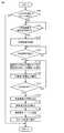
以下、図4を参照してECU200で実行される制御処理の一例を説明する。図4は、ECU200で実行される処理の一例を示すフローチャートである。 Hereinafter, an example of the control process executed by the
ステップ(以下、ステップをSと記載する)100にて、ECU200は、EV50がスリープ状態であるか否かを判定する。ECU200は、たとえば、EV50をスリープ状態に移行させる場合にオン状態に設定され、スリープ状態から復帰する場合にオフ状態に設定されるフラグの状態に基づいてEV50がスリープ状態であるか否かを判定してもよい。ECU200は、たとえば、所定の実行条件が成立する場合にEV50をスリープ状態に移行させる。所定の実行条件は、たとえば、コネクタが接続された状態であって、かつ、充電が要求されないという条件を含む。EV50がスリープ状態であると判定される場合(S100にてYES)、処理はS102に移される。 In step 100 (hereinafter, step is referred to as S) 100, the
S102にて、ECU200は、充電装置56の起動指令を受信したか否かを判定する。ECU200は、たとえば、サーバ30から通信装置210を経由して充電装置56の起動要求を示す信号を受信する場合に、充電装置56の起動指令を受信したと判定する。充電装置56の起動指令を受信したと判定される場合(S102にてYES)、処理はS104に移される。 In S102, the
S104にて、ECU200は、充電装置56を起動させる。ECU200は、たとえば、充電リレー57が接続状態になるように制御するとともに、充電装置56を用いたバッテリ110の充電が可能な状態になるように充電装置56およびバッテリ110の充電に関連する電気機器を作動可能な状態になるように制御する。 In S104, the
S106にて、ECU200は、DR信号を受信したか否かを判定する。ECU200は、たとえば、サーバ30から通信装置210を経由してDR信号を受信する場合にDR信号を受信したと判定する。DR信号を受信したと判定される場合(S106にてYES)、処理はS108に移される。 In S106, the
S108にて、ECU200は、電流センサ56aによって検出される電流Iと、電圧センサ56bによって検出される電圧Vとを乗算して充電電力Pを算出する。 In S108, the
S110にて、ECU200は、算出された充電電力Pを前回の計算において算出された積算値に加算して今回の積算値を充電量として算出する。なお、ECU200は、充電電力Pが所定時間当たりの電力であって、前回の計算時点から今回の計算時点までのサンプル時間が所定時間と異なる場合には、充電電力Pに所定の係数(たとえば、所定時間とサンプル時間との比)を乗算して前回の積算値に加算してもよい。 In S110, the
S112にて、ECU200は、DR対応が終了したか否かを判定する。ECU200は、たとえば、DR要請に従った充電が完了する場合にDR対応が終了したと判定する。DR対応が終了したと判定される場合(S112にてYES)、処理はS114に移される。 In S112, the
S114にて、ECU200は、充電装置56の作動を停止させる。ECU200は、充電装置56の作動を停止させるとともに充電リレー57が遮断状態になるように制御する。S116にて、ECU200は、充電電力Pの積算を停止させる。S118にて、ECU200は、積算値を管理装置であるサーバ10に送信する。具体的には、ECU200は、積算を停止させた時点における積算値を今回のDR対応における充電量として車両IDとともにサーバ30に送信する。 At S114, the
積算値を受信したサーバ30は、たとえば、サーバ20を経由してサーバ10に車両IDとともに積算値を送信する。サーバ10は、車両ID毎に積算値をメモリに記憶させる。サーバ10は、車両ID毎に記憶された積算値から今回のDR要請に対する対応(すなわち、DR信号を受信してからDR対応が終了するまでの間におけるEV50のバッテリ110の充電対応)の貢献分を特定し、特定された貢献分に対応するインセンティブを各EV50のユーザに対して設定する。 The
S120にて、ECU200は、EV50をスリープ状態に移行させる。ECU200は、たとえば、充電装置56などのEV50がスリープ状態である場合に休止される電気機器の作動を停止させる。 In S120, the
なお、EV50がスリープ状態でないと判定される場合(S100にてNO)、この処理は終了される。また、充電装置56の起動指令を受信していないと判定される場合(S102にてNO)、処理はS102に戻される。さらに、DR指令を受信していないと判定される場合(S106にてNO)、処理はS106に戻される。さらに、DR対応が終了していないと判定される場合(S112にてNO)、処理はS108に戻される。 If it is determined that the EV50 is not in the sleep state (NO in S100), this process is terminated. If it is determined that the activation command of the charging
以上のような構成を有するEV50の動作について説明する。たとえば、EV50のインレット59にEVSE40のコネクタが接続された状態であって、かつ、EV50がスリープ状態である場合を想定する。 The operation of the EV50 having the above configuration will be described. For example, assume that the connector of the
コネクタが接続された状態であって、かつ、EV50がスリープ状態であるため(S100にてYES)、充電装置56の起動指令を受信するか否かが判定される(S102)。 Since the connector is connected and the EV50 is in the sleep state (YES in S100), it is determined whether or not to receive the activation command of the charging device 56 (S102).
サーバ30は、第2DR実行指示を受信してから、DR信号を送信する前に各EV50に対して充電装置56の起動指令を送信する。 After receiving the second DR execution instruction, the
サーバ30から充電装置56の起動指令を受信する場合(S102にてYES)、充電装置56が起動される(S104)。 When receiving the activation command of the charging
サーバ30は、充電装置56の起動指令の送信後に、DR信号を各EV50に送信する。サーバ30からDR信号を受信すると(S106にてYES)、各EV50においてバッテリ110の充電が実施される。このとき、電流センサ56aと電圧センサ56bとによって検出される電流Iおよび電圧Vとを乗算して充電電力Pが算出される(S108)。 The
算出された充電電力Pが前回の計算において算出された積算値に加算されて今回の積算値が算出される(S110)。 The calculated charging power P is added to the integrated value calculated in the previous calculation to calculate the integrated value this time (S110).
DR対応が終了した場合には(S112にてYES)、充電装置56の作動が停止されることによって(S114)、バッテリ110の充電が停止される。そして、積算値の算出が停止され(S116)、算出の停止時点における積算値がサーバ30に送信され(S118)、EV50は、スリープ状態に移行される(S120)。そのため、各EV30の充電量についての情報が各EV50の車両IDとともにサーバ30およびサーバ20を経由してサーバ10に送信される。サーバ10は、各EV50の充電量から今回のDR要請に対する貢献分を特定し、特定された貢献分に対応するインセンティブを設定する。 When the DR correspondence is completed (YES in S112), the operation of the charging
以上のようにして、本実施の形態に係る車両によると、EV50において検出された充電電力を用いて算出された充電量についての情報が通信装置210を用いて管理装置であるサーバ10に送信されるため、たとえば、同じEVSE40に複数のEV50が接続され、並行して充電が行なわれる場合でも、サーバ10において各EV50における充電量を精度高く取得することができる。したがって、電力平準化の要請に従って外部の電力網と授受される電力量を精度高く取得可能な車両を提供することができる。 As described above, according to the vehicle according to the present embodiment, the information about the charge amount calculated by using the charge power detected in the
以下、変形例について記載する。
上述の実施の形態では、ECU200は、DR要請に従って電力網からバッテリ110に電力が供給される場合に、電流センサ56aおよび電圧センサ56bを用いて充電電力を検出し、検出された充電電力を積算して算出される充電量についての情報を通信装置210を用いて管理装置であるサーバ10に送信するものとして説明したが、貢献分に対応するパラメータとしては、充電量に限定されるものではない。Hereinafter, modification examples will be described.
In the above-described embodiment, the
たとえば、ECU200は、DR要請に従って電力網と蓄電装置との間で電力が授受される場合に、電流センサ56aおよび電圧センサ56bを用いて授受電力を検出し、検出された授受電力を積算して算出される授受電力量についての情報を通信装置210を用いて管理装置であるサーバ10に送信できればよく、貢献分に対応するパラメータとしては、放電量であってもよい。 For example, when power is exchanged between the power grid and the power storage device in accordance with a DR request, the
具体的には、上述の実施の形態では、EV50は、EVSE40(すなわち、電力網)から電力供給を受けることによってEV50に搭載されるバッテリ110の充電が可能な構成を有するものとして説明したが、EV50は、バッテリ110の充電が可能な構成に加えて、または、代えて、EV50に搭載されるバッテリ110の電力をEVSE40(すなわち、電力網)に供給(放電)することが可能な構成を有するようにしてもよい。 Specifically, in the above-described embodiment, the EV50 has been described as having a configuration in which the
この場合、ECU200は、たとえば、DR要請に従って蓄電装置から電力網に電力が供給される場合に、電流センサ56aおよび電圧センサ56bを用いて放電電力を検出し、検出された放電電力を積算して算出される放電量についての情報を通信装置210を用いて管理装置であるサーバ10に送信してもよい。 In this case, for example, when power is supplied from the power storage device to the power network in accordance with the DR request, the
さらに上述の実施の形態では、電流センサ56aおよび電圧センサ56bを用いて充電電力を算出するものとして説明したが、特に、電流センサ56aおよび電圧センサ56bを用いて充電電力を算出することに限定されるものではなく、たとえば、バッテリ110や充電装置56に設けられる他の電流センサおよび他の電圧センサを用いて充電電力を算出してもよい。なお、好ましくは、インレット59から充電装置56までの間に設けられる電流センサおよび電圧センサを用いて充電電力を算出することが望ましい。このようにすると、EVSE40からEV50に供給された充電量を、EV50におけるロス(充電装置56内でのロス、EV50の他の電気機器での消費分)等を考慮することなく取得することができる。 Further, in the above-described embodiment, the charging power is calculated using the
さらに上述の実施の形態では、電流センサ56aおよび電圧センサ56bを用いて充電電力を算出するものとして説明したが、インレット59からバッテリ110までの間に設けられる他の電流センサの検出結果と、他の電圧センサの検出結果とを用いて電流センサ56aの検出精度と、電圧センサ56bの検出精度とが正常であるか否かを判定してもよい。ECU200は、たとえば、電流センサ56aの検出値と、他の電流センサの検出値との差分の大きさがしきい値以下である場合に電流センサ56aの検出精度が正常であると判定してもよい。さらに、ECU200は、たとえば、電圧センサ56bの検出値と、他の電圧センサの検出値との差分の大きさがしきい値以下である場合に電圧センサ56bの検出精度が正常であると判定してもよい。 Further, in the above-described embodiment, the charging power is calculated using the
上述の実施の形態では、電流センサ56aおよび電圧センサ56bを用いて充電電力を算出するものとして説明したが、たとえば、ECU200によって充電電力がゼロになるように充電装置56が制御される場合において、電流センサ56aのゼロからのずれ量(オフセット量)を検出し、検出されたオフセット量を用いて電流センサ56aの検出値を補正してもよい。このようにすると、電流センサ56aの検出精度を向上し、充電量を精度高く算出することができる。 In the above-described embodiment, the charging power is calculated using the
なお、上記した変形例は、その全部または一部を適宜組み合わせて実施してもよい。
今回開示された実施の形態はすべての点で例示であって制限的なものではないと考えられるべきである。本発明の範囲は上記した説明ではなくて特許請求の範囲によって示され、特許請求の範囲と均等の意味および範囲内でのすべての変更が含まれることが意図される。In addition, the above-mentioned modification may be carried out by appropriately combining all or a part thereof.
It should be considered that the embodiments disclosed this time are exemplary in all respects and not restrictive. The scope of the present invention is shown not by the above description but by the scope of claims, and it is intended that all modifications within the meaning and scope equivalent to the scope of claims are included.
1 VGIシステム、10,20,20A,20B,20C,30,30A,30C サーバ、11 発電所、12 送配電設備、13 スマートメータ、40 EVSE、50 EV、51 MG、52 動力伝達ギア、53 駆動輪、54 PCU、55 SMR、56 充電装置、56a 電流センサ、56b 電圧センサ、57 充電リレー、59 インレット、70 データセンタ、80 携帯端末、110 バッテリ、200 ECU、210 通信装置、E1 電力会社、E2 上位アグリゲータ、E3 下位アグリゲータ、NL1,NL2,PL1,PL2 電源線。 1 VGI system, 10, 20, 20A, 20B, 20C, 30, 30A, 30C server, 11 power plant, 12 power transmission and distribution equipment, 13 smart meter, 40 EVSE, 50 EV, 51 MG, 52 power transmission gear, 53 drive Wheel, 54 PCU, 55 SMR, 56 Charging device, 56a current sensor, 56b voltage sensor, 57 charging relay, 59 inlet, 70 data center, 80 mobile terminal, 110 battery, 200 ECU, 210 communication device, E1 power company, E2 Upper aggregator, E3 lower aggregator, NL1, NL2, PL1, PL2 power line.
Claims (1)
Translated fromJapanese車両の外部の電力網と前記蓄電装置との間で授受される授受電力を検出する検出装置と、
電力平準化の要請に従って前記蓄電装置において授受される授受電力量を管理する、前記車両の外部に設けられる管理装置との間で、通信可能に構成される通信装置と、
前記管理装置に所定の情報を送信するように前記通信装置を制御する制御装置とを備え、
前記制御装置は、前記要請に従って前記電力網と前記蓄電装置との間で電力が授受される場合に、前記検出装置を用いて前記授受電力を検出し、検出された前記授受電力を積算して算出される前記授受電力量についての情報を前記通信装置を用いて前記管理装置に送信する、車両。Power storage device and
A detection device that detects the power exchanged between the power grid outside the vehicle and the power storage device, and
A communication device configured to be able to communicate with a management device provided outside the vehicle, which manages the amount of power exchanged and received by the power storage device in accordance with a request for power leveling.
A control device for controlling the communication device so as to transmit predetermined information to the management device is provided.
When power is transferred between the power grid and the power storage device in accordance with the request, the control device detects the transmitted / received power using the detection device, and integrates and calculates the detected power transferred / received. A vehicle that transmits information about the amount of power exchanged and received to the management device using the communication device.
Priority Applications (1)
| Application Number | Priority Date | Filing Date | Title |
|---|---|---|---|
| JP2019143923AJP2021027697A (en) | 2019-08-05 | 2019-08-05 | vehicle |
Applications Claiming Priority (1)
| Application Number | Priority Date | Filing Date | Title |
|---|---|---|---|
| JP2019143923AJP2021027697A (en) | 2019-08-05 | 2019-08-05 | vehicle |
Publications (1)
| Publication Number | Publication Date |
|---|---|
| JP2021027697Atrue JP2021027697A (en) | 2021-02-22 |
Family
ID=74663252
Family Applications (1)
| Application Number | Title | Priority Date | Filing Date |
|---|---|---|---|
| JP2019143923APendingJP2021027697A (en) | 2019-08-05 | 2019-08-05 | vehicle |
Country Status (1)
| Country | Link |
|---|---|
| JP (1) | JP2021027697A (en) |
Cited By (3)
| Publication number | Priority date | Publication date | Assignee | Title |
|---|---|---|---|---|
| JP2023019449A (en)* | 2021-07-29 | 2023-02-09 | トヨタ自動車株式会社 | Power system and power calculation method |
| JP2023064547A (en)* | 2021-10-26 | 2023-05-11 | マツダ株式会社 | Moving body temperature control system |
| JP2023170632A (en)* | 2022-05-19 | 2023-12-01 | トヨタ自動車株式会社 | Vehicle control device |
Citations (5)
| Publication number | Priority date | Publication date | Assignee | Title |
|---|---|---|---|---|
| JP2010284039A (en)* | 2009-06-05 | 2010-12-16 | Softbank Mobile Corp | Power supply system |
| JP2016521536A (en)* | 2013-04-08 | 2016-07-21 | ジョ−ライン コーポレーション リミテッド | Location-based power intermediary module, electric vehicle and intermediary server, and user authentication outlet or connector used therefor |
| WO2017009978A1 (en)* | 2015-07-15 | 2017-01-19 | 本田技研工業株式会社 | V2g system and charging/discharging control method |
| JP2017529038A (en)* | 2014-08-25 | 2017-09-28 | トヨタ自動車株式会社 | Regional charge control service |
| JP2018011507A (en)* | 2014-11-17 | 2018-01-18 | シーメンス インダストリー インコーポレイテッドSiemens Industry, Inc. | System and method for EVSE-based energy automation, management and protection |
- 2019
- 2019-08-05JPJP2019143923Apatent/JP2021027697A/enactivePending
Patent Citations (5)
| Publication number | Priority date | Publication date | Assignee | Title |
|---|---|---|---|---|
| JP2010284039A (en)* | 2009-06-05 | 2010-12-16 | Softbank Mobile Corp | Power supply system |
| JP2016521536A (en)* | 2013-04-08 | 2016-07-21 | ジョ−ライン コーポレーション リミテッド | Location-based power intermediary module, electric vehicle and intermediary server, and user authentication outlet or connector used therefor |
| JP2017529038A (en)* | 2014-08-25 | 2017-09-28 | トヨタ自動車株式会社 | Regional charge control service |
| JP2018011507A (en)* | 2014-11-17 | 2018-01-18 | シーメンス インダストリー インコーポレイテッドSiemens Industry, Inc. | System and method for EVSE-based energy automation, management and protection |
| WO2017009978A1 (en)* | 2015-07-15 | 2017-01-19 | 本田技研工業株式会社 | V2g system and charging/discharging control method |
Cited By (4)
| Publication number | Priority date | Publication date | Assignee | Title |
|---|---|---|---|---|
| JP2023019449A (en)* | 2021-07-29 | 2023-02-09 | トヨタ自動車株式会社 | Power system and power calculation method |
| JP7582111B2 (en) | 2021-07-29 | 2024-11-13 | トヨタ自動車株式会社 | Power system and power calculation method |
| JP2023064547A (en)* | 2021-10-26 | 2023-05-11 | マツダ株式会社 | Moving body temperature control system |
| JP2023170632A (en)* | 2022-05-19 | 2023-12-01 | トヨタ自動車株式会社 | Vehicle control device |
Similar Documents
| Publication | Publication Date | Title |
|---|---|---|
| JP7264032B2 (en) | Server and power management system | |
| US11358490B2 (en) | Power feed system | |
| US20190061535A1 (en) | Electric vehicle power management systems | |
| US11400832B2 (en) | Electrically powered vehicle | |
| US20210053459A1 (en) | Electric power system and vehicle | |
| US20210129689A1 (en) | Notification controller, mobile body, electric power system, and notification method | |
| JP2021027696A (en) | Charging control system | |
| JP2021027697A (en) | vehicle | |
| CN113285501B (en) | Electric power measuring system, electric power measuring method and electric power measuring device | |
| US11491890B2 (en) | Vehicle management apparatus, vehicle, and vehicle management method | |
| US20220234467A1 (en) | Server, power management system, and energy management method | |
| JP2021191196A (en) | Charge control device | |
| CN117639029A (en) | Power management system and power management method | |
| JP2022039338A (en) | Management device | |
| JP2021005957A (en) | Charge control device | |
| US20240067009A1 (en) | Power management system and power management method | |
| JP7740177B2 (en) | Power Management System | |
| JP2024037386A (en) | Power management system and power management method |
Legal Events
| Date | Code | Title | Description |
|---|---|---|---|
| A621 | Written request for application examination | Free format text:JAPANESE INTERMEDIATE CODE: A621 Effective date:20211020 | |
| A131 | Notification of reasons for refusal | Free format text:JAPANESE INTERMEDIATE CODE: A131 Effective date:20220614 | |
| A02 | Decision of refusal | Free format text:JAPANESE INTERMEDIATE CODE: A02 Effective date:20221206 |