JP2021023705A - Input device for operation manipulator - Google Patents
Input device for operation manipulatorDownload PDFInfo
- Publication number
- JP2021023705A JP2021023705AJP2019146232AJP2019146232AJP2021023705AJP 2021023705 AJP2021023705 AJP 2021023705AJP 2019146232 AJP2019146232 AJP 2019146232AJP 2019146232 AJP2019146232 AJP 2019146232AJP 2021023705 AJP2021023705 AJP 2021023705A
- Authority
- JP
- Japan
- Prior art keywords
- force
- compensation amount
- input device
- force compensation
- link
- Prior art date
- Legal status (The legal status is an assumption and is not a legal conclusion. Google has not performed a legal analysis and makes no representation as to the accuracy of the status listed.)
- Granted
Links
Images


Landscapes
- Manipulator (AREA)
Abstract
Translated fromJapaneseDescription
Translated fromJapanese本発明は、手術マニピュレータの入力装置に関する。 The present invention relates to an input device for a surgical manipulator.
手術マニピュレータの入力装置として、例えば、特許文献1に記載された、マスター装置が知られている。このマスター装置では、3軸のアームの先端部にリストが回動自在に設けられている。リストは自由度3のジンバルを構成する3軸(関節)のリンク連結体に形成されている。この3軸のリンク連結体の先端部に操作者が操作するハンドルが形成されている。そして、プロセッサが、リストの各軸(関節)の回転位置に基づいて、アームの先端部に対してリストを回動させることによって、リストの各軸を直角に近い角度に制御する。これにより、ハンドルがいずれの方角に回転しても、マスターのリンク連結体の慣性及び摩擦を最小にすることができる(特許文献1の段落[0029]参照)。 As an input device for a surgical manipulator, for example, a master device described in
ところで、手術ロボット(手術マニピュレータ)を用いて手術するためには、操作者が微妙な力加減でハンドルを操作する必要がある。そのため、マスター装置(手術マニピュレータの入力装置)には、操作者がハンドル(操作部)を操作するために必要な力(以下、操作力という場合がある)を調整できることが要求される。 By the way, in order to perform an operation using a surgical robot (surgical manipulator), it is necessary for the operator to operate the steering wheel with a delicate amount of force. Therefore, the master device (input device of the surgical manipulator) is required to be able to adjust the force required for the operator to operate the handle (operation unit) (hereinafter, may be referred to as an operation force).
しかしながら、特許文献1の記載では、そもそも、操作力の一部となるマスターのリンク連結体の慣性力が補償されているか否かが、明らかではない。従って、当然のことながら、特許文献1は、慣性力を含む操作力を調整することについては全く言及(開示)していない。そのため、操作力を調整できないとう課題があった。 However, in the description of
本発明は上記のような課題を解決するためになされたもので、操作力を調整できる手術マニピュレータの入力装置を提供することを目的としている。 The present invention has been made to solve the above problems, and an object of the present invention is to provide an input device for a surgical manipulator capable of adjusting an operating force.
上記目的を達成するために、本発明のある形態(aspect)に係る手術マニピュレータの入力装置は、関節を有し、先端部に操作者が操作する操作部を備えるマスターアームと、前記マスターアームの関節を、動力伝達要素を介して駆動するモータと、前記操作者の前記操作部の操作により動く前記動力伝達要素の速度及び加速度の少なくともいずれかに基づいて前記マスターアームの慣性力及び粘性力の少なくともいずれかに対する力補償量を演算し、当該力補償量の力補償を行うよう前記モータの動作を制御する制御器と、を備え、前記制御器は、前記慣性力及び粘性力の少なくともいずれかに対する力補償量を調整するように構成されている。 In order to achieve the above object, the input device of the surgical manipulator according to a certain aspect of the present invention has a master arm having a joint and having an operation unit operated by an operator at a tip portion, and the master arm. The inertial force and viscous force of the master arm based on at least one of the speed and acceleration of the motor that drives the joint via the power transmission element and the power transmission element that is moved by the operation of the operation unit of the operator. A controller that calculates a force compensation amount for at least one of them and controls the operation of the motor so as to perform force compensation of the force compensation amount is provided, and the controller is provided with at least one of the inertial force and the viscous force. It is configured to adjust the amount of force compensation against.
ここで、「力補償量」とは、マスターアームの慣性力及び粘性力の少なくともいずれかの一部又は全部を打ち消す力の大きさを意味する。また、操作者がマスターアームを操作すると、操作者にマスターアームからの抵抗力が加わる。この抵抗力は、マスターアームの慣性及び加速度に比例する慣性力と、マスターアームの粘性及び速度に比例する粘性力とを含む。以下では、抵抗力の補償量を「抵抗力補償量」と呼び、慣性力の補償量を「慣性力補償量」と呼び、粘性力の補償量を「粘性力補償量」と呼ぶ。従って、マスターアームに加わる重力を無視した場合(又は、操作力に重力補償がなされている場合)、抵抗力と抵抗力補償量との差が、操作者がマスターアームを操作するために必要な力である操作力になる。 Here, the "force compensation amount" means the magnitude of the force that cancels at least a part or all of the inertial force and the viscous force of the master arm. Further, when the operator operates the master arm, a resistance force from the master arm is applied to the operator. This resistance force includes an inertial force proportional to the inertia and acceleration of the master arm and a viscous force proportional to the viscosity and velocity of the master arm. Hereinafter, the compensation amount of resistance force is referred to as "resistance compensation amount", the compensation amount of inertial force is referred to as "inertial force compensation amount", and the compensation amount of viscous force is referred to as "viscous force compensation amount". Therefore, when the gravity applied to the master arm is ignored (or when the operating force is gravitationally compensated), the difference between the resistance force and the resistance force compensation amount is necessary for the operator to operate the master arm. It becomes an operation force that is a force.
上記構成によれば、制御器が、操作者の操作部の操作により動く動力伝達要素の速度及び加速度の少なくともいずれかに基づいてマスターアームの慣性力及び粘性力の少なくともいずれかに対する力補償量を演算し、この力補償量の力補償を行うようモータの動作を制御するので、例えば、力補償量として、マスターアームの慣性力に対する力補償量、マスターアームの粘性力に対する力補償量、又はマスターアームの慣性力及び粘性力に対する力補償量を選択することによって、操作力をきめ細かく設定できる。その上、制御器が、前記慣性力及び粘性力の少なくともいずれかに対する力補償量を調整するので、操作力を調整できる。 According to the above configuration, the controller provides a force compensation amount for at least one of the inertial force and the viscous force of the master arm based on at least one of the speed and acceleration of the power transmission element moved by the operation of the operation unit of the operator. Since the operation of the motor is controlled so as to calculate and perform force compensation of this force compensation amount, for example, as the force compensation amount, the force compensation amount for the inertial force of the master arm, the force compensation amount for the viscous force of the master arm, or the master The operating force can be finely set by selecting the force compensation amount for the inertial force and the viscous force of the arm. Moreover, since the controller adjusts the force compensation amount for at least one of the inertial force and the viscous force, the operating force can be adjusted.
補償量の大きい順にランク付けされた複数のランク付け力補償量を記憶する記憶器と、前記複数のランク付け力補償量のいずれかを指定するための入力器と、を備え、前記制御器は、前記慣性力及び粘性力の少なくともいずれかに対する力補償量を、前記入力器によって指定されたランク付け力補償量に調整するように構成されていてもよい。 The controller includes a storage device that stores a plurality of ranking force compensation amounts ranked in descending order of compensation amount, and an input device for designating one of the plurality of ranking force compensation amounts. , The force compensation amount for at least one of the inertial force and the viscous force may be adjusted to the ranking force compensation amount specified by the input device.
この構成によれば、操作者が好む操作力となるように力補償する補償量にランク付けされたランク付け力補償量を入力器に入力すると、制御器が、力補償量を、指定されたランク付け力補償量に調整するので、操作力を、操作者が好む操作力に設定できる。 According to this configuration, when the ranking force compensation amount ranked in the compensation amount for force compensation so as to be the operation force preferred by the operator is input to the input device, the controller specifies the force compensation amount. Since the ranking force compensation amount is adjusted, the operating force can be set to the operating force preferred by the operator.
指定力補償量を複数の前記操作者のそれぞれに対応させて記憶する記憶器と、前記指定力補償量に対応する操作者を特定するための入力器と、を備え、前記制御器は、前記慣性力及び粘性力の少なくともいずれかに対する力補償量を、前記入力器によって特定された前記操作者に対応する指定力補償量に調整するように構成されていてもよい。 The controller includes a storage device that stores a designated force compensation amount corresponding to each of the plurality of operators and an input device for identifying an operator corresponding to the designated force compensation amount. The force compensation amount for at least one of the inertial force and the viscous force may be adjusted to the designated force compensation amount corresponding to the operator specified by the input device.
この構成によれば、各操作者が希望する操作力となるように力補償する指定力補償量を、当該各操作者に対応させて記憶器に記憶させることによって、操作力を、操作者が希望する操作力に設定できる。 According to this configuration, the operator can obtain the operating force by storing the specified force compensation amount for compensating the force so as to be the desired operating force for each operator in the storage device corresponding to each operator. You can set the desired operating force.
前記制御器は、前記動力伝達要素の速度を取得する速度取得部と、前記動力伝達要素の加速度を取得する加速度取得部と、前記速度取得部が取得した前記動力伝達要素の速度と前記マスターアームの粘性とに基づいて前記粘性力に対する力補償量を演算する粘性力補償量演算部と、前記加速度取得部が取得した前記動力伝達要素の加速度と前記マスターアームの慣性とに基づいて前記慣性力に対する力補償量を演算する慣性力補償量演算部と、前記粘性力に対する力補償量及び前記慣性力に対する力補償量の力補償を行うための電力を、前記モータに供給する電力変換器と、を備えてもよい。 The controller includes a speed acquisition unit that acquires the speed of the power transmission element, an acceleration acquisition unit that acquires the acceleration of the power transmission element, the speed of the power transmission element acquired by the speed acquisition unit, and the master arm. The viscous force compensation amount calculation unit that calculates the force compensation amount for the viscous force based on the viscosity of, and the inertial force based on the acceleration of the power transmission element acquired by the acceleration acquisition unit and the inertia of the master arm. An inertial force compensation amount calculation unit that calculates the force compensation amount for the motor, and a power converter that supplies power for performing force compensation for the force compensation amount for the viscous force and the force compensation amount for the inertial force to the motor. May be provided.
この構成によれば、操作力をきめ細かく設定でき、その上、操作力を調整できる手術マニピュレータの入力装置を実現できる。 According to this configuration, it is possible to realize an input device for a surgical manipulator in which the operating force can be finely set and the operating force can be adjusted.
前記マスターアームは、複数の前記関節を有し、前記入力装置は、複数の前記動力伝達要素と、各前記モータが各前記関節を、各前記動力伝達要素を介して駆動する複数の前記モータと、を備え、前記制御器は、各前記関節について、前記操作者の前記操作部の操作により動く各前記動力伝達要素の速度及び加速度に基づいて、前記マスターアームの各関節により駆動される部分の慣性力及び粘性力の少なくともいずれかに対する力補償量を演算し、当該力補償量の力補償を行うよう各前記モータの動作を制御するよう構成されていてもよい。 The master arm has a plurality of the joints, and the input device includes a plurality of the power transmission elements and a plurality of the motors in which each of the motors drives each of the joints via the power transmission elements. The controller comprises, for each of the above joints, a portion of the portion driven by each of the joints of the master arm based on the speed and acceleration of each of the power transmission elements that are moved by the operation of the operating unit of the operator. The force compensation amount for at least one of the inertial force and the viscous force may be calculated, and the operation of each of the motors may be controlled so as to perform the force compensation of the force compensation amount.
この構成によれば、複数の関節を有するマスターアームを備える手術マニピュレータの入力装置において、操作力をきめ細かく設定でき、その上、操作力を調整できる。 According to this configuration, in the input device of the surgical manipulator including the master arm having a plurality of joints, the operating force can be finely set, and the operating force can be adjusted.
前記制御器は、各前記関節毎に、前記マスターアームの各関節により駆動される部分の慣性力及び粘性力の少なくともいずれかに対する力補償量を調整するように構成されていてもよい。 The controller may be configured to adjust the force compensation amount for at least one of the inertial force and the viscous force of the portion driven by each joint of the master arm for each of the joints.
この構成によれば、複数の関節を有するマスターアームを備える手術マニピュレータの入力装置において、各関節毎に、力補償量を調整できるので、よりきめ細かく操作力を調整できる。 According to this configuration, in the input device of the surgical manipulator including the master arm having a plurality of joints, the force compensation amount can be adjusted for each joint, so that the operating force can be adjusted more finely.
前記制御器は、さらに、前記マスターアームの姿勢が重力によって変化しないように前記モータの動作を制御するよう構成されていてもよい。 The controller may be further configured to control the operation of the motor so that the posture of the master arm does not change due to gravity.
この構成によれば、操作者がマスターアームを停止させると、マスターアームが停止位置に止まる。 According to this configuration, when the operator stops the master arm, the master arm stops at the stop position.
前記制御器は、さらに、前記操作者の前記操作部の操作により動く前記動力伝達要素の位置に基づいて前記操作部の位置を演算し、この演算した前記操作部の位置を手術マニピュレータに出力するよう構成されていてもよい。 The controller further calculates the position of the operation unit based on the position of the power transmission element moved by the operation of the operation unit of the operator, and outputs the calculated position of the operation unit to the surgical manipulator. It may be configured as follows.
この構成によれば、手術マニピュレータを操作部の位置に従って動作させることができる。 According to this configuration, the surgical manipulator can be operated according to the position of the operation unit.
本発明は、操作力をきめ細かく設定でき、その上、操作力を調整できる手術マニピュレータの入力装置を提供できるという効果を奏する。 INDUSTRIAL APPLICABILITY The present invention has an effect that an input device of a surgical manipulator capable of finely setting an operating force and further adjusting the operating force can be provided.
以下、本発明の実施の形態を、図面を参照しながら説明する。なお、以下では全ての図面を通じて同一又は相当する要素には同一の参照符号を付して、その重複する説明を省略する。また、以下の図は、本発明を説明するための図であるので、それらの図において本発明に無関係な要素が省略される場合、誇張等のために寸法が正確でない場合、複数の図において、互いに対応する要素が一致しない場合等がある。 Hereinafter, embodiments of the present invention will be described with reference to the drawings. In the following, the same or corresponding elements will be designated by the same reference numerals throughout the drawings, and duplicate description thereof will be omitted. Further, since the following figures are diagrams for explaining the present invention, if elements unrelated to the present invention are omitted in those figures, or if the dimensions are not accurate due to exaggeration or the like, in a plurality of figures. , The elements corresponding to each other may not match.
なお、本発明は、以下の実施形態に限定されない。 The present invention is not limited to the following embodiments.
(実施形態)
[構成]
{ハードウェアの構成}
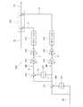
図1は、本発明の実施形態1に係る手術マニピュレータの入力装置を含むロボット支援手術システムの一例の概要を示す模式図である。図2は、図1のロボット支援手術システムが備えるハンドコントロールの一例の外観の概要を示す模式図である。以下では、図1及び図2の上下方向を絶対空間における上下方向として説明する。(Embodiment)
[Constitution]
{Hardware configuration}
FIG. 1 is a schematic diagram showing an outline of an example of a robot-assisted surgery system including an input device of a surgical manipulator according to the first embodiment of the present invention. FIG. 2 is a schematic view showing an outline of the appearance of an example of a hand control provided in the robot-assisted surgery system of FIG. In the following, the vertical direction of FIGS. 1 and 2 will be described as the vertical direction in the absolute space.
図1及び図2を参照すると、ロボット支援手術(RAS:Robotically-Assisted Surgical)システム200は、ポジショナ201と、手術マニピュレータ202と、ハンドコントロール100と、を備える。 Referring to FIGS. 1 and 2, the Robotically-Assisted Surgical (RAS)
<ロボット支援手術システム200>
図1を参照すると、例えば、手術室に手術台203が配置され、手術台203の上に患者204が横たえられる。手術台203の近傍にポジショナ201が配置される。ポジショナ201は、例えば多関節ロボットで構成される。ポジショナ201の先端部のベース201aに多関節ロボットで構成される手術マニピュレータ202が取り付けられている。手術マニピュレータ202は、例えば、基部と、アーム部401と、エンドエフェクタ部とを有し、基部がベース201aに固定され、基部とリンク404、リンク404同士、リンク404とエンドエフェクタ部とが複数の関節によって連結されている。基部には、複数(ここでは、例えば、4本)のアーム部401が連結されている。複数のアーム部401の先端には、エンドエフェクタ部として、それぞれ、手術ツール402が取り付けられる。<Robot-assisted
Referring to FIG. 1, for example, the operating table 203 is arranged in the operating room, and the
ポジショナ201は、手術マニピュレータ202を、当該手術マニピュレータ202が患者204に手術を施すのに適した位置に搬送する。 The
<ハンドコントロール100>
図2には、ハンドコントロール100の概要が示されている。なお、図2は、ハンドコントロール100の概念を判り易く示す図であり、そのため、図2には、特に入力装置2の細部の構造が、後述する図3〜図8に示される具体的な構造と異なって示されている。<
FIG. 2 shows an outline of the
図2を参照すると、ハンドコントロール100は、操作者(手術する医師)が手術マニピュレータ202の動作を制御して手術を行うための装置である。ハンドコントロール100は、ポジショナ201及び手術マニピュレータ202と、有線又は無線により、電気的に接続されている。ハンドコントロール100は、例えば、手術台の近傍又は別室に配置される。 Referring to FIG. 2, the
ハンドコントロール100は、ここでは、本体1と、入力装置2と、複数のペダル4と、表示部5と、ビュアー(不図示)と、を備える。 Here, the
本体1は、側面から見て略L字状に形成されており、本体1の、当該本体1に向かって右側及び左側の部分に、それぞれ、右入力装置2A及び左入力装置2B(手術マニピュレータの入力装置)が設けられている。右入力装置2A及び左入力装置2Bは、操作者が、それぞれ、右手及び左手で操作するためのものである。右入力装置2A及び左入力装置2Bは、それぞれ、スレーブロボットとしての手術マニピュレータ202の各アーム部401に対するマスター入力装置として機能する。 The
本体1の上部には、前方に突出するようにU字状の支持部材3が設けられている。支持部材3の前端部の中央部に表示部5が設けられている。表示部5は、例えば、タッチパネルで構成されていて、操作者がハンドコントロール100に各種の設定を行うための情報を表示又は入力するための画面として機能する。ビュアー(不図示)は、ハンドコントロール100の上部に設けられるが、ビュアーの構成及び機能は良く知られているので、図2では、入力装置2を見易くするために、図示を省略している。ビュアーには、手術マニピュレータ202のアーム部401の先端にエンドエフェクタ部として取り付けられた内視鏡(手術ツール402)によって撮像された画像が表示される。 A
本体1の下部には、前方に突出するように複数(ここでは4本)のペダル4が設けられている。複数のペダル4は、右入力装置2A及び左入力装置2Bと手術マニピュレータ202の各アームとの接続の切り替え、表示部5に表示される画像のズーム等を行うものである。 A plurality of (here, four)
操作者は、例えば、ハンドコントロール100の前に配置された椅子に腰かけた状態で、ビュアーに表示される患者204の体内の画像を見ながら、右入力装置2A又は左入力装置2Bを右又は左の手で操作して手術を行う。 The operator right or left the
<手術マニピュレータ202の入力装置2>
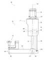
図3は、図2に示す入力装置2の概要を模式的に示す側面図である。図3には、入力装置2の構成が簡略化されて示されている。入力装置2の具体的な構造例は、図4〜図8を参照されたい。図3には、右入力装置2Aが示されている。左入力装置2Bは、右入力装置2Aの左右方向の構造を逆にしただけである。従って、左入力装置2Bの説明を省略する。以下では、便宜上、図3の上下方向を及び左右方向を、それぞれ、右入力装置2Aの上下方向及び前後方向とする。右入力装置2Aは、初期状態において、図3に示す基準姿勢を取る。<
FIG. 3 is a side view schematically showing an outline of the
図3を参照すると、右入力装置2Aは、側面視において、略L字状の基準姿勢を取る。以下、右入力装置2Aの基準姿勢を単に「基準姿勢」という場合がある。右入力装置2Aは、マスターアーム10を備える。マスターアーム0は、アーム部11とリスト部12とを備える。 Referring to FIG. 3, the
{アーム部11}
アーム部11は、例えば、基体21と、第1リンク22と、第2リンク23と、第3リンク24とを備える。基体21はハンドコントロール100の本体1に固定されている。基体21の上下方向における一方の端部(ここでは下端部)に、第1リンク22の一方の端部(ここでは上端部)が、第1関節JT1を介して、上下方向に延びる第1回動軸線A1の周りに回動自在に連結されている。第1リンク22の他方の端部(ここでは下端部)に、第2リンク23の一方の端部(ここでは上端部)が、第2関節JT2を介して、第1回動軸線A1に直交し且つ左右方向に延びる第2回動軸線A2の周りに回動自在に連結されている。第2リンク23の他方の端部(ここでは下端部)に、第3リンク24の一方の端部(基準姿勢における後端部)が、第3関節JT3を介して、第2回動軸線A2に平行に延びる第3回動軸線A3の周りに回動自在に連結されている。また、第1リンク22の他方の端部には、揺動部材25の一方の端部が第2回動軸線A2の周りに回動自在に設けられている。揺動部材25の他方の端部には、補助リンク26の一方の端部(ここでは、上端部)が第9回動軸線A9の周りに回動自在に連結されている。第9回動軸線A9は、第2回動軸線A2に平行で且つ第2回動軸線から所定距離だけ離れて延在する。補助リンク26の他方の端部(ここでは下端部)は、第3リンクの一方の端部に第10回動軸線A10の周りに回動自在に連結されている。第10回動軸線A10は、第3回動軸線A3に平行で且つ第3回動軸線から第3リンク24の一方の端向かう方向に上記所定距離だけ離れて延在する。つまり、補助リンク26及び第2リンク23は、平行リンクを構成している。{Arm part 11}
The
第3リンク24の他方の端部(基準姿勢における前端部)には、リスト部12が、第4関節JT4を介して、第4回動軸線A4の周りに回動自在に連結されている。第4回動軸線A4は、第3回動軸線A3及び第10回動軸線A10を含む平面に直交するように延在する。 A
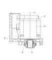
図4は、図3の入力装置のアーム部11のうちの肩部の縦断面を示す断面図である。図4を参照すると、肩部は基体21で構成され、基体21は、枠体状に形成されている。基体21には、第1モータM1が下向きに設けられている。具体的には、第1モータM1は、主軸S1が第1回動軸線A1と同軸になるように設けられている。第1モータM1には、第1モータM1の回転角を検知する第1回転角検知器E1が設けられている。第1回転角検知器E1は、回転角を検知できるものであればよく、例えば、エンコーダ、回転計等で構成される。第1回転角検知器E1は、ここでは、第1モータM1の主軸S1に直結されたエンコーダで構成される。主軸S1は、円筒状の連結部材62を用いて、第1リンク22の第1回転軸R1(図5参照)と同軸に突き合わせ接続されている。 FIG. 4 is a cross-sectional view showing a vertical cross section of a shoulder portion of the
図5は、図3の右入力装置2Aのアーム部11のうちの上腕部の縦断面を示す断面図である。図5を参照すると、アーム部11の上腕部は、第1リンク22、第2リンク23、及び補助リンク26を含む。第1リンク22は、枠体状に形成されている。第1リンク22の一方の端部(ここでは、上端部)には、第1回転軸R1が設けられている。上述のように、第1回転軸R1は、第1モータM1の主軸S1と同軸に接続されている。この第1回転軸R1及び第1モータM1によって、第1関節JT1が構成されており、これにより、第1リンク22が、基体21に対し、第1回動軸線A1の周りに自在に回動することが可能であり、第1リンク22の回動による第1モータM1の回転角を第1回転角検知器E1によって検知することが可能であり、且つ、第1モータM1によって第1回転軸R1を回転駆動することが可能である。 FIG. 5 is a cross-sectional view showing a vertical cross section of the upper arm portion of the
第2リンクは、中空の棒状に形成されている。第2リンク23の一方の端部(上端部)には、第2回転軸R2が設けられている。この第2回転軸R2が、軸受51を介して、第1リンク22の他方の端部(下端部)に、第2回動軸線A2の周りに回動自在に取り付けられている。この第2回転軸R2及び軸受51によって、第2関節JT2が構成されており、これにより、第2リンク23が、第1リンク22に対し、第2回動軸線A2の周りに自在に回動することが可能である。 The second link is formed in the shape of a hollow rod. A second rotation shaft R2 is provided at one end (upper end) of the
第2回転軸R2には、従動プーリー33が設けられている。一方、第1リンク22には、主軸S2の中心軸が第2回動軸線A2に平行になるように、第2モータM2が設けられている。第2モータM2には、第2モータM2の回転角を検知する第2回転角検知器E2が設けられている。第2回転角検知器E2は、回転角を検知できるものであればよく、例えば、エンコーダ、回転計等で構成される。第2回転角検知器E2は、ここでは、第2モータM2の主軸S2に直結されたエンコーダで構成される。 A driven pulley 33 is provided on the second rotating shaft R2. On the other hand, the
第2モータM2の主軸S2には、駆動プーリー32が設けられている。この駆動プーリー32と従動プーリー33とにベルト34が巻き掛けられている。これにより、第2リンク23の回動による第2モータM2の回転角を第2回転角検知器E2によって検知することが可能であり、且つ、第2モータM2によって第2回転軸R2を回転駆動することが可能である。 A
さらに、第2リンク23の適所(ここでは中央部)と第1リンク22との間に引張コイルバネ(補助バネ)SP1が設けられている。この引張コイルバネSP1は、中心軸が第2回動軸線A2と第3回動軸線A3とに直交するように設けられている。また、この引張コイルバネSP1は、第2リンク23が基準姿勢から回動すると、その回動方向に所定のトルクを第2回転軸R2に対して作用させるように設計されている。この所定のトルクは、アーム部11の第2リンク23から先の部分及びリスト部12の自重によって第2回転軸R2に発生するトルク(以下、重力トルクという場合がある)の一部を打ち消すようなトルクに設定されている。これにより、第2回転軸R2に発生する重力トルクの一部が引張コイルバネSP1によって打ち消される。 Further, a tension coil spring (auxiliary spring) SP1 is provided between an appropriate position (here, the central portion) of the
第3リンク24は、棒状の箱体に形成されていて、内部に主要な要素が収容されている。第3リンク24の一方の端部(後端部)には、第3回転軸R3が設けられている。この第3回転軸R3が、軸受52を介して、第2リンク23の他方の端部に、第3回動軸線A3の周りに回動自在に取り付けられている。この第3回転軸R3及び軸受52によって、第3関節JT3が構成されており、これにより、第3リンク24が、第2リンク23に対し、第3回動軸線A3の周りに自在に回動することが可能である。 The
一方、揺動部材25は細長い板状に形成されていて、この揺動部材25の一方の端部に、第11回転軸R11が設けられている。この第11回転軸R11が、軸受53を介して、第1リンク22の他方の端部に第2回動軸線A2の周りに回動自在に取り付けられている。 On the other hand, the
また、揺動部材25の他方の端部に第9回転軸R9が設けられている。この第9回転軸R9が、軸受(不図示)を介して、補助リンク26の一方の端部に第9回動軸線A9の周りに回動自在に連結されている。 Further, a ninth rotation shaft R9 is provided at the other end of the
また、第3リンク24の一方の端と第3関節JT3との間の部分に第10回転軸R10が設けられている。この第10回転軸が、軸受(不図示)を介して、補助リンク26の他方の端部に第10回動軸線A10の周りに回動自在に連結されている。なお、上述のように、補助リンク26と第2リンク23とは平行リンクを構成している。 Further, a tenth rotation axis R10 is provided at a portion between one end of the
さらに、第11回転軸R11には、従動プーリー44が設けられている。一方、第1リンク22の適宜な位置に、主軸S3の中心軸が第11回動軸線A11に平行になるように、第3モータM3が設けられている。第3モータM3には、第3モータM3の回転角を検知する第3回転角検知器E3が設けられている。第3回転角検知器E3は、回転角を検知できるものであればよく、例えば、エンコーダ、回転計等で構成される。第3回転角検知器E3は、ここでは、第3モータM3の主軸S3に直結されたエンコーダで構成される。 Further, the eleventh rotation shaft R11 is provided with a driven
第3モータM3の主軸S3には、駆動プーリー42が設けられている。この駆動プーリー42と従動プーリー33とにベルト34が巻き掛けられている。 A
以上の補助リンク26に関連する構成によれば、第3リンク24が回動すると、補助リンク26が第2リンク23に平行に移動し、それによって揺動部材25が揺動し、この揺動部材25の揺動に応じて、従動プーリー44、駆動プーリー42、及び第3モータM3が順に回転する。従って、この一連の動作により、第3リンク24の回動による第3モータM3の回転角を第3回転角検知器E3によって検知することが可能である。また、この一連の動作の逆の動作により、第3モータM3によって第3回転軸R3を回転駆動することが可能である。 According to the configuration related to the
さらに、揺動部材25と第1リンク22との間に圧縮コイルバネ(不図示)が設けられている。この圧縮コイルバネは、常時、揺動部材を下方に回動させるトルクを発生するように設計されている。このトルクは、アーム部11の第3リンク24及びリスト部12の自重によって第9回転軸R9に発生する重力トルクの一部を打ち消すようなトルクに設定されている。これにより、第9回転軸R9に発生する重力トルクの一部がこのコイルバネによって打ち消される。 Further, a compression coil spring (not shown) is provided between the
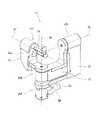
{リスト部12}
図6は、図3の入力装置のリスト部12の外観を示す斜視図である。図6は、基準姿勢にあるリスト部12を示している。図6を参照すると、リスト部12は、例えば、第4リンク71と、第5リンク72と、第6リンク73と、第7リンクとしての操作部74とを備える。第4リンク71、第5リンク72、第6リンク73、及び操作部74は、3軸(自由度3)のジンバルを構成している。具体的には、第5リンク72が、第4リンク71に対し、第5回動軸線A5の周りに回動自在であり、第6リンク73が、第5リンク72に対し、第5回動軸線A5に直交する第6回動軸線A6の周りに回動自在であり、操作部74が、第6リンク73に対し、第5回動軸線A5及び第6回動軸線A6に直交する第7回動軸線A7の周りに回動自在である。従って、操作者は、操作部74を、これら3つの回動軸線A5〜A7の交点を中心に回動させて、任意の方向に向けることができる。{List part 12}
FIG. 6 is a perspective view showing the appearance of the
図3及び図6を参照すると、第4リンク71はL字状に形成されていて、この第4リンク71の一方の端部(基準姿勢における前端部)が、第4関節JT4を介して、第4回動軸線の周りに回動自在に第3リンク24(図3参照)の他方の端部(基準姿勢における前端部)に連結されている。第4回動軸線A4は、第3回動軸線A3及び第10回動軸線A10を含む平面に直交する。 With reference to FIGS. 3 and 6, the
図6を参照すると、第4リンク71の他方の端部(基準姿勢における後端部)に、第5リンク72の一方の端部(基準姿勢における後端端部)が、第5関節JT5を介して、第4回動軸線A4に直交する第5回動軸線A5の周りに回動自在に連結されている。第5リンク72は、第4リンク71より一回り小さいL字状に形成されている。第5リンク72の他方の端部(基準姿勢における前端部)に、第6リンク73の一方の端部(基準姿勢における右端部)が、第6関節JT6を介して、第6回動軸線A6の周りに回動自在に連結されている。第6リンク73は、第5リンク72より一回り小さいL字状に形成されている。第6リンク73の他方の端部(基準姿勢における左端部)に、操作部74の一方の端部(基準姿勢における左端部)が、第7関節JT7を介して、第7回動軸線A7の周りに回動自在に連結されている。操作部74は、棒状の本体と、この本体に設けられた一対の円筒状の指挿入部74aとを備える。一対の指挿入部74aは、操作者がこれらに親指と人差し指とを挿入し、親指と人差し指とで、あたかも物をつまんだり放したりするように一対の指挿入部74aを操作することができるように構成されている。 Referring to FIG. 6, one end of the fifth link 72 (rear end in the reference posture) attaches the fifth joint JT5 to the other end of the fourth link 71 (rear end in the reference posture). Via, it is rotatably connected around the fifth rotation axis A5 orthogonal to the fourth rotation axis A4. The
次に、リスト部12の詳細な構造の一例を説明する。 Next, an example of the detailed structure of the
図7は、図6のリスト部12の第4リンク71及び第5リンク72の縦断面を示す断面図である。図8は、図6のリスト部12の第6リンク73及び操作部74の縦断面を示す断面図である。図7はリスト部12を、第5回動軸線A5及び第6回動軸線A6を含む平面で切断した断面を示し、図8はリスト部12を、第6回動軸線A6及び第7回動軸線A7を含む平面で切断した断面を示す。 FIG. 7 is a cross-sectional view showing a vertical cross section of the
図7を参照すると、第4リンク71は、L字状の箱体に形成されていて、主要な要素が箱体の内部に収容されている。第4リンク71の一方の端部(前端部)には、第4回転軸R4が設けられている。この第4回転軸R4が、軸受81を介して、第3リンク24の他方の端部(前端部)に、第4回動軸線A4の周りに回動自在に取り付けられている。この第4回転軸R4及び軸受81によって、第4関節JT4が構成されており、これにより、第4リンク71が、第3リンク24に対し、第4回動軸線A4の周りに自在に回動することが可能である。 Referring to FIG. 7, the
また、第3リンク24の内部には、第4モータM4が、主軸S4の中心軸が第4回動軸線A4と直交するように設けられている。第4モータM4には、第4モータM4の回転角を検知する第4回転角検知器E4が設けられている。第4回転角検知器E4は、回転角を検知できるものであればよく、例えば、エンコーダ、回転計等で構成される。第4回転角検知器E4は、ここでは、第4モータM4の主軸S4に直結されたエンコーダで構成される。第4モータM4の主軸S4は、ベベルギア機構G1を介して第4回転軸R4に接続されている。これにより、第4リンク71の回動による第4モータM4の回転角を第4回転角検知器E4によって検知することが可能であり、且つ、第4モータM4によって第4回転軸R4を回転駆動することが可能である。 Further, inside the
第5リンク72は、L字状の箱体に形成されていて、主要な要素が箱体の内部に収容されている。第5リンク72の一方の端部(後端部)には、第5回転軸R5が設けられている。この第5回転軸R5が、軸受82を介して、第4リンク71の他方の端部(後端部)に、第5回動軸線A5の周りに回動自在に取り付けられている。この第5回転軸R5及び軸受82によって、第5関節JT5が構成されており、これにより、第5リンク72が、第4リンク71に対し、第5回動軸線A5の周りに自在に回動することが可能である。 The
また、第4リンク71の内部には、第5モータM5が、主軸S5の中心軸が第5回動軸線A5と直交するように設けられている。第5モータM5には、第5モータM5の回転角を検知する第5回転角検知器E5が設けられている。第5回転角検知器E5は、回転角を検知できるものであればよく、例えば、エンコーダ、回転計等で構成される。第5回転角検知器E5は、ここでは、第5モータM5の主軸S5に直結されたエンコーダで構成される。第5モータM5の主軸S5は、ベベルギア機構G2を介して第5回転軸R5に接続されている。これにより、第5リンク72の回動による第5モータM5の回転角を第5回転角検知器E5によって検知することが可能であり、且つ、第5モータM5によって第5回転軸R5を回転駆動することが可能である。 Further, inside the
さらに、第4リンク71の適所(ここでは基準姿勢における後端部の下端部)と第5回転軸R5との間に圧縮コイルバネSP2(補助バネ)が設けられている。この圧縮コイルバネSP2は、中心軸が第4回動軸線A4に平行で且つ第5回動軸線A5に直交するように設けられている。また、この圧縮コイルバネSP2は、第5リンク72が基準姿勢から回動すると、その回動方向に所定のトルクを第5リンク72に対して作用させるように設計されている。この所定のトルクは、リスト部12の第5リンクから先の部分の自重によって第5回転軸R5に発生する重力トルクの一部を打ち消すようなトルクに設定されている。これにより、第5回転軸R5に発生する重力トルクの一部が圧縮コイルバネSP2によって打ち消される。 Further, a compression coil spring SP2 (auxiliary spring) is provided between an appropriate position of the fourth link 71 (here, the lower end of the rear end portion in the reference posture) and the fifth rotation shaft R5. The compression coil spring SP2 is provided so that the central axis is parallel to the fourth rotation axis A4 and orthogonal to the fifth rotation axis A5. Further, the compression coil spring SP2 is designed so that when the
図7及び図8を参照すると、第6リンク73は、L字状の箱体に形成されていて、主要な要素が箱体の内部に収容されている。第6リンク73の一方の端部(右端部)には、第6回転軸R6が設けられている。この第6回転軸R6が、軸受83を介して、第5リンク72の他方の端部(前端部)に、第6回動軸線A6の周りに回動自在に取り付けられている。この第6回転軸R6及び軸受83によって、第6関節JT6が構成されており、これにより、第6リンク73が、第5リンク72に対し、第6回動軸線A6の周りに自在に回動することが可能である。 With reference to FIGS. 7 and 8, the
また、第5リンク72の内部には、第6モータM6が、主軸S6の中心軸が第6回動軸線A6と直交するように設けられている。第6モータM6には、第6モータM6の回転角を検知する第6回転角検知器E6が設けられている。第6回転角検知器E6は、回転角を検知できるものであればよく、例えば、エンコーダ、回転計等で構成される。第6回転角検知器E6は、ここでは、第6モータM6の主軸S6に直結されたエンコーダで構成される。第6モータM6の主軸S6は、ベベルギア機構G3を介して第6回転軸R6に接続されている。これにより、第6リンク73の回動による第6モータM6の回転角を第6回転角検知器E6によって検知することが可能であり、且つ、第6モータM6によって第6回転軸R6を回転駆動することが可能である。 Further, inside the
図8を参照すると、操作部74の一方の端部(左端部)には、第7回転軸R7が設けられている。この第7回転軸R7が、軸受84を介して、第6リンク73の他方の端部(左端部)に、第7回動軸線A7の周りに回動自在に取り付けられている。この第7回転軸R7及び軸受84によって、第7関節JT7が構成されており、これにより、操作部74が、第6リンク73に対し、第7回動軸線A7の周りに自在に回動することが可能である。 Referring to FIG. 8, a seventh rotation shaft R7 is provided at one end (left end) of the
また、第6リンク73の内部には、第7モータM7が、主軸S7の中心軸が第7回動軸線A7と直交するように設けられている。第7モータM7には、第7モータM7の回転角を検知する第7回転角検知器E7が設けられている。第7回転角検知器E7は、回転角を検知できるものであればよく、例えば、エンコーダ、回転計等で構成される。第7回転角検知器E7は、ここでは、第7モータM7の主軸S7に直結されたエンコーダで構成される。第7モータM7の主軸S7は、ベベルギア機構G4を介して第7回転軸R7に接続されている。これにより、操作部74の回動による第7モータM7の回転角を第7回転角検知器E7によって検知することが可能であり、且つ、第7モータM7によって第7回転軸R7を回転駆動することが可能である。 Further, inside the
<動力伝達経路>
図3及び図5を参照すると、第1モータM1から第1関節JT1に至る動力伝達経路は、第1モータM1の主軸S1及び第1回転軸R1で構成される。第2モータM2から第2関節JT2に至る動力伝達経路は、第2モータM2の主軸S2、駆動プーリー32、ベルト34、従動プーリー33、及び第2回転軸R2で構成される。第3モータM3から第3関節JT3に至る動力伝達経路は、第3モータM3の主軸S3、駆動プーリー42、ベルト45、従動プーリー44、第11回転軸R11、揺動部材25、第9回転軸R9、補助リンク26、第10回転軸R10、第3リンク24、及び第3回転軸R3で構成される。<Power transmission path>
Referring to FIGS. 3 and 5, the power transmission path from the first motor M1 to the first joint JT1 is composed of the main shaft S1 and the first rotation shaft R1 of the first motor M1. The power transmission path from the second motor M2 to the second joint JT2 is composed of the main shaft S2 of the second motor M2, the
図7を参照すると、第4モータM4から第4関節JT4に至る動力伝達経路は、第4モータM4の主軸S4、べベルギア機構G1、及び第4回転軸R4で構成される。第5モータM5から第5関節JT5に至る動力伝達経路は、第5モータM5の主軸S5、べベルギア機構G2、及び第5回転軸R5で構成される。第6モータM6から第6関節JT6に至る動力伝達経路は、第6モータM6の主軸S6、べベルギア機構G3、及び第6回転軸R6で構成される。図8を参照すると、第7モータM7から第7関節JT7に至る動力伝達経路は、第7モータM7の主軸S7、べベルギア機構G4、及び第7回転軸R7で構成される。 Referring to FIG. 7, the power transmission path from the fourth motor M4 to the fourth joint JT4 is composed of the main shaft S4 of the fourth motor M4, the bevel gear mechanism G1, and the fourth rotation shaft R4. The power transmission path from the fifth motor M5 to the fifth joint JT5 is composed of the main shaft S5 of the fifth motor M5, the bevel gear mechanism G2, and the fifth rotation shaft R5. The power transmission path from the sixth motor M6 to the sixth joint JT6 is composed of the main shaft S6 of the sixth motor M6, the bevel gear mechanism G3, and the sixth rotation shaft R6. Referring to FIG. 8, the power transmission path from the 7th motor M7 to the 7th joint JT7 is composed of the main shaft S7 of the 7th motor M7, the bevel gear mechanism G4, and the 7th rotation shaft R7.
<抵抗力補償量算出の基礎となる動力伝達要素>
後述する抵抗力補償量算出の基礎となる動力伝達要素は、ここでは、第1乃至第7モータM1〜M7の主軸S1〜S7である。これらの主軸S1〜S7の回転角を、それぞれ、回転角センサである第1乃至第7回転角検知器E1〜E7が検知し、これらの回転角AGに基づいて、後述する抵抗力補償量が、それぞれ、演算される。なお、抵抗力補償量算出の基礎となる動力伝達要素が、他の動力伝達要素であってもよい。例えば、第1乃至第7関節JT1〜JT7の第1乃至第7回転軸R1〜R7、又はベベルギア機構G1〜G4の各ギアであってもよい。この場合、これらの動力伝達要素にエンコーダを設け、それらの回転角を検知すればよい。<Power transmission element that is the basis for calculating resistance compensation amount>
Here, the power transmission elements that are the basis for calculating the resistance compensation amount, which will be described later, are the spindles S1 to S7 of the first to seventh motors M1 to M7. The rotation angles of these spindles S1 to S7 are detected by the first to seventh rotation angle detectors E1 to E7, which are rotation angle sensors, respectively, and the resistance compensation amount described later is calculated based on these rotation angle AGs. , Each is calculated. The power transmission element that is the basis for calculating the resistance compensation amount may be another power transmission element. For example, the first to seventh rotation axes R1 to R7 of the first to seventh joints JT1 to JT7, or the gears of the bevel gear mechanisms G1 to G4 may be used. In this case, encoders may be provided on these power transmission elements to detect their rotation angles.
{制御系統の構成}
図9は、右入力装置2A及び手術マニピュレータ202の制御系統の構成の一例を示す機能ブロック図である。{Control system configuration}
FIG. 9 is a functional block diagram showing an example of the configuration of the control system of the
図9を参照すると、右入力装置2Aは、入力装置制御器C1を備える。入力装置制御器C1は、例えば、右入力装置2A及び左入力装置2Bに共通に設けられている。入力装置制御器C1による両者の制御は同様であるので、ここでは、右入力装置2Aに関する制御のみ説明し、左入力装置2Bに関する制御の説明を省略する。なお、右入力装置2A及び左入力装置2Bに、それぞれ、入力装置制御器C1を設けてもよい。入力装置制御器C1の詳細な構成は後で説明する。入力装置制御器C1は、例えば、ハンドコントロール100の適所に設けられる。 Referring to FIG. 9, the
右入力装置2Aでは、第1乃至第7関節JT1〜JT7にそれぞれ対応する第1乃至第7モータM1〜M7の回転角AGを、それぞれ、第1乃至第7回転角検知器E1〜E7が検知し、検知した第1乃至第7モータM1〜M7の回転角AGを、それぞれ、入力装置制御器C1に出力する。入力装置制御器C1は、入力された第1乃至第7モータM1〜M7の回転角AGに基づいて操作部74の位置(位置指令信号)Pを生成し、この操作部74の位置Pをマニピュレータ制御器C2に出力する。また、入力装置制御器C1は、入力された第1乃至第7モータM1〜M7の回転角AGに基づいて駆動電流CRを第1乃至第7モータM1〜M7に、それぞれ、出力する。 In the
手術マニピュレータ202では、アーム部401のリンク404及び手術ツール402を連結する1以上の関節にそれぞれ対応する1以上のモータM202の回転角を、それぞれ、1以上の回転角検知器E202が検知し、検知した1以上のモータM202の回転角を、それぞれ、マニピュレータ制御器C2に出力する。マニピュレータ制御器C2は、入力装置制御器C1から入力された操作部74の位置(位置指令信号)Pに基づいて、手術ツール402が操作部74の位置に対応する位置に位置するような駆動電流を1以上のモータM202に出力する。これにより、手術ツール402が操作部74の位置に対応する位置に位置するようにリンク404の動作が制御される。この際、1以上の回転角検知器E202が検知する回転角が、手術ツール402の位置をフィードバック制御するために用いられる。 In the
なお、入力装置2Aの操作部74の姿勢及び動作が、別途、適宜なセンサ(不図示)により検知され、入力装置制御器C1を経由してマニピュレータ制御器C2に入力される。マニピュレータ制御器C2は、手術ツール402が、入力装置2Aの操作部74の姿勢に対応する姿勢を取るとともに入力装置2Aの操作部74の動作に対応する動作を行うよう手術ツール02を制御する。マニピュレータ制御器C2は、例えば、ハンドコントロール100の適所に設けられる。 The posture and operation of the
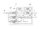
<入力装置制御器C1>
図10は、図9の入力装置制御器C1の構成の一例を示す機能ブロック図である。図10を参照すると、入力装置制御器C1は、位置演算部501と、重力補償量演算部502と、抵抗力補償量演算部503と、制御部(制御器)504と、サーボアンプ(電力変換器)505と、記憶部(記憶器)506と、入力部(入力器)507とを備える。<Input device controller C1>
FIG. 10 is a functional block diagram showing an example of the configuration of the input device controller C1 of FIG. Referring to FIG. 10, the input device controller C1 includes a
位置演算部501、重力補償量演算部502、抵抗力補償量演算部503、制御部504、及び記憶部506は、例えば、プロセッサ(不図示)とメモリ(不図示)とを有する演算器(不図示)で構成される。演算器として、マイクロコントローラ等が例示される。プロセッサとして、例えば、CPU、MPU、FPGA(Field Programmable Gate Array)、PLC(Programmable Logic Controller)等が例示される。メモリとして、ROM、RAM等のプロセッサの内部メモリ、ハードディスクドライブ等の外部メモリが例示される。 The
位置演算部501、重力補償量演算部502、抵抗力補償量演算部503、制御部504、及び記憶部506は、演算器のメモリに格納された所定の制御プログラムを演算器のプロセッサが読み出して実行することによって実現される機能ブロックである。実際には、当該演算器が、位置演算部501、重力補償量演算部502、抵抗力補償量演算部503、制御部504、及び記憶部506として動作する。なお、位置演算部501、重力補償量演算部502、及び抵抗力補償量演算部503は、電子回路等のハードウェアで構成されてもよい。また、入力装置制御器C1は、単独の演算器で構成されてもよく、複数の演算器で構成されてもよい。 The
位置演算部501は、入力された第1乃至第7モータM1〜M7の回転角AGに基づいて操作部74の位置(位置指令信号)Pを生成する。この演算は周知であるので、その説明を省略する。 The
重力補償量演算部502は、入力された第1乃至第7モータM1〜M7の回転角AGに基づいてマスターアーム10の姿勢を求め、当該姿勢によって各関節JT1〜JT7の各回転軸R1〜R7に発生する重力トルクを打ち消す重力打消しトルクを演算する。この場合、重力補償量演算部502は、得られた姿勢から回転軸R1〜R7毎に定まる重力トルクをそれぞれ演算する。そして、コイルバネが設けられている関節JT2、JT3、JT5においては、重力トルクからコイルバネが発生するトルクを差し引いたトルクと反対方向のトルクを重力打消しトルクとし、コイルバネが設けられていない関節JT1、JT4、JT6、JT7においては、重力トルクと反対方向のトルクを重力打消しトルクとする。これらの第1乃至第7関節JT1〜JT7の重力打消しトルクが重力補償量である。重力補償量演算部502は、第1乃至第7関節JT1〜JT7の重力補償量を、当該重力補償量の重力補償を行うための電流指令Igとして送出する。 The gravity compensation
抵抗力補償量演算部503は、入力された第1乃至第7モータM1〜M7の回転角AGに基づいて、第1乃至第7関節JT1〜JT7の抵抗力補償量を演算し、これらの抵抗力補償量を、当該抵抗力補償量の抵抗力補償を行うための電流指令Idとして送出する。加算部518は、重力補償用の電流指令Igと抵抗力補償用の電流指令Idとを加算して補償電流指令Icを生成する。 The resistance compensation
サーボアンプ(電力変換器)505は、補償電流指令Icに対応する駆動電流CRを第1乃至第7モータM1〜M7にそれぞれ出力する。これにより、第1乃至第7モータM1〜M7が、補償電流指令Ic(重力補償用の電流指令Ig+抵抗力補償用の電流指令Id)に応じたトルクを発生し、その結果、マスターアーム10の姿勢が重力によって変化しないように制御されるとともに、マスターアーム10の抵抗力に対し力補償された操作力が発生する。ここで、本実施形態では、操作力に重力補償がなされているので、抵抗力と抵抗力補償量との差が、操作者がマスターアーム10を操作するために必要な力である操作力になる。 The servo amplifier (power converter) 505 outputs the drive current CR corresponding to the compensation current command Ic to the first to seventh motors M1 to M7, respectively. As a result, the first to seventh motors M1 to M7 generate torque according to the compensation current command Ic (current command Ig for gravity compensation + current command Id for resistance compensation), and as a result, the
記憶部506は、各種のデータ等を記憶する。特に、記憶部506には、ランク付け力補償量が予め記憶されている。図12は、ランク付け力補償量の大きさのランクの一例を示すググラフである。図12を参照すると、力補償量が、粘性力補償量と慣性力補償量とで構成されていて、0.0から1.0の値を取る粘性調整係数Kdが粘性力補償量の相対的な大きさを表し、0.0から1.0の値を取る慣性調整係数Kmが慣性力補償量の相対的な大きさを表す。そして、これらが、0.2刻みで5段階に分けられ、値の大きい順にA〜Eのランクにランク付けされている。 The
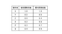
また、記憶部507は、後述するように入力部507から指定力補償量が操作者IDと対応付けて入力されると、これらを操作者毎の指定力補償量として記憶する。図13は、操作者毎の指定力補償量の一例を示すググラフである。図13において、X〜Qは、操作者IDを表す。図13を参照すると、指定力補償量が粘性力補償量と慣性力補償量とで構成されている。そして、粘性力補償量及び慣性力補償量をそれぞれ表す粘性調整係数Kd及び慣性調整係数Kmが操作者IDと対応させられて、操作者毎の指定力補償量が構成されている。 Further, when the designated force compensation amount is input from the
入力部507は、操作者が各種データを制御部504に入力するための装置である。入力部507は、例えば、キーボード、マウス、タッチパネル等で構成される。操作者は、例えば、力補償量のランク、並びに、操作者毎の指定力補償量としての慣性調整係数Km、粘性調整係数Kd及び操作者ID、を入力部507によって入力する。従って、入力部507は、力補償量のランクを指定するための入力装置及び指定力補償量に対応する操作者を特定するための入力装置として機能する。なお、この指定力補償量を、入力部507以外の入力手段によって制御部504に入力するように構成してもよい。そのような入力手段として、データ通信ネットワークを介する入力手段が例示される。 The
制御部504は、位置演算部501で生成された操作部74の位置(位置指令信号)Pをマニピュレータ制御器C2に出力する。また、制御部504は、入力部507から入力された各種データを適宜処理する。 The
特に、制御部504は、入力部507からランク付け力補償量のランクA〜Eが入力されると、入力されたランクA〜Eに対応する慣性調整係数Km及び粘性調整係数Kdを読み出して、後述する慣性調整係数乗算部516及び粘性調整係数乗算部520においてそれぞれ用いられる慣性調整係数Km及び粘性調整係数Kdを、それぞれ、読み出した慣性調整係数Km及び粘性調整係数Kdに置き換える。 In particular, when the ranking force compensation amounts of ranks A to E are input from the
また、制御部504は、入力部507から操作者毎の指定力補償量としてセットで入力された慣性調整係数Km、粘性調整係数Kd、及び操作者ID(X〜Q)を、慣性調整係数Km及び粘性調整係数Kdと操作者ID(X〜Q)とを対応させて、記憶部506に記憶させる。そして、入力部507から操作者ID(X〜Q)が入力されると、当該操作者IDに対応する慣性調整係数Km及び粘性調整係数Kdを記憶部506から読み出し、後述する慣性調整係数乗算部516及び粘性調整係数乗算部520においてそれぞれ用いられる慣性調整係数Km及び粘性調整係数Kdを、それぞれ、読み出した慣性調整係数Km及び粘性調整係数Kdに置き換える。なお、操作者が、任意の慣性調整係数Km及び粘性調整係数Kdを入力して、慣性調整係数乗算部516及び粘性調整係数乗算部520におけるそれらを任意の慣性調整係数Km及び粘性調整係数Kdに変更できるようにしてもよい。 Further, the
<抵抗力補償量演算部503>
図11は、図9の抵抗力補償量演算部503の構成を示すブロック図である。図11は、第1乃至第7関節JT1〜JT7のうちの1つの関節に対応する抵抗力補償量演算部503を示す。つまり、操作力における抵抗力補償は、各関節JT1〜JT7毎に行われる。<Resistance compensation
FIG. 11 is a block diagram showing a configuration of the resistance compensation
図11を参照すると、抵抗力補償量演算部503は、回転角遅延部511、第1減算部(速度取得部)512、回転角速度遅延部513、第2減算部(加速度取得部)514、慣性係数乗算部(慣性力補償演算部)515、慣性調整係数乗算部516、1次フィルタ517、加算部518、粘性調整係数乗算部(粘性力補償量演算部)519、粘性調整係数乗算部520、1次フィルタ521、並びに第1及び第2スイッチSW1,SW2を備える。 With reference to FIG. 11, the resistance compensation
第1乃至第7回転角検知器E1〜E7で検知される回転角AGは、所定のサンプリング間隔でサンプリングされる。回転角遅延部511は、入力される回転角AGを1サンプリング間隔だけ遅延する。第1減算部512は、現在時刻の回転角AGから回転角遅延部511で遅延された回転角AGdを減算して、回転角速度vを生成する。ここで、相前後する回転角AGの差分ΔAGは、サンプリング間隔Δtが単位時間である場合、回転角AGの微分である回転角速度vに相当する。 The rotation angles AG detected by the first to seventh rotation angle detectors E1 to E7 are sampled at predetermined sampling intervals. The rotation
回転角速度遅延部513は、入力される回転角速度vを1サンプリング間隔だけ遅延する。第2減算部514は、現在時刻の回転角速度vから回転角速度遅延部513で遅延された回転角速度vdを減算して、回転角加速度αを生成する。ここで、相前後する回転角速度vの差分Δvは、サンプリング間隔Δtが単位時間である場合、回転角速度vの微分である回転角加速度αに相当する。 The rotation angular
第1スイッチSW1は、ON又はOFFすることによって、回転角加速度αの慣性係数乗算部515への伝送を許容又は阻止する。第1スイッチSW1は、入力部507から第1スイッチSW1のON指令又はOFF指令が入力されると、制御部504によってON又はOFFされる。 The first switch SW1 allows or prevents transmission of the rotational angular acceleration α to the inertial
慣性係数乗算部515は、回転角加速度αに慣性係数Mを乗算して、慣性力補償量fiを生成する。慣性調整係数乗算部516は、慣性力補償量fiに慣性調整係数Kmを乗算して、調整後慣性力補償量を生成する。ここで、慣性調整係数Kmは、0.0以上で且つ1.0以下の範囲の数値である。1次フィルタ517は、調整後慣性力補償量からサンプリングに起因するノイズ等を除去し、これを慣性力補償用の電流指令Iiとして送出する。 The inertial
なお、1次フィルタ517の時定数を調整可能にしてもよい。この場合、操作者が入力部507から1次フィルタ517の時定数を入力すると、制御部504が、1次フィルタ517の時定数を入力された時定数に置き換える。このように時定数を調整可能にする理由は、ノイズが入力装置2毎に異なるからである。これは、後述する1次フィルタ521に関しても同様である。 The time constant of the
一方、第2スイッチSW2は、ON又はOFFすることによって、回転角速度vの粘性係数乗算部519への伝送を許容又は阻止する。第2スイッチSW2は、入力部507から第2スイッチSW2のON指令又はOFF指令が入力されると、制御部504によってON又はOFFされる。 On the other hand, the second switch SW2 allows or prevents transmission of the rotational angular velocity v to the viscosity
粘性係数乗算部519は、回転角速度vに粘性係数Dを乗算して、粘性力補償量fvを生成する。粘性調整係数乗算部520は、粘性力補償量fvに粘性調整係数Kdを乗算して、調整後粘性力補償量を生成する。ここで、粘性調整係数Kdは、0.0以上で且つ1.0以下の範囲の数値である。1次フィルタ521は、調整後粘性力補償量からサンプリングに起因するノイズ等を除去し、これを粘性力補償用の電流指令Ivとして送出する。慣性力補償用の電流指令Ii及び粘性力補償用の電流指令Ivが、抵抗力補償用の電流指令Idを構成する。 The viscosity
なお、1次フィルタ521の時定数を調整可能にしてもよい。この場合、操作者が入力部507から1次フィルタ521の時定数を入力すると、制御部504が、1次フィルタ521の時定数を入力された時定数に置き換える。 The time constant of the primary filter 521 may be adjustable. In this case, when the operator inputs the time constant of the primary filter 521 from the
加算部518は、この抵抗力補償用の電流指令Idと重力補償用の電流指令Igとを加算して補償電流指令Icを生成する。
[動作]
まず、右入力装置2A及び手術マニピュレータ202の動作を説明する。The
[motion]
First, the operation of the
図3及び図6を参照すると、操作者は、例えば、右入力装置2Aの操作部74の一対の指挿入部74aに親指と人差し指とを挿入する。そして、操作者が、操作部74を左右に動かすと、アーム部11が、第1関節JT1の第1回動軸線A1を中心に左右に回動する。操作者が操作部74を前後に動かすと、アーム部11が、第2関節JT2の第2回動軸線A2を中心に前後に回動する。操作者が、操作部74を上下に動かすと、アーム部11が、第3関節JT3の第3回動軸線A3を中心に上下に回動する。操作者が、リスト部12を左右に回転させると、リスト部12が、第4関節JT4の第4回動軸線A4を中心に左右に回転する。操作者が、操作部74の向き(姿勢)を変えるように操作部74を操作すると、操作部74がその変えようとする向きに動く(姿勢を取る)。従って、操作者は、入力装置2Aを意図するように操作することができる。 With reference to FIGS. 3 and 6, the operator inserts, for example, a thumb and an index finger into a pair of
右入力装置2Aの操作部74が操作されると、この操作が入力装置制御器C1によって位置指令信号Pに変換され、マニピュレータ制御器C2が、この位置指令信号Pに従って、手術マニピュレータ202の選択されたアーム部401の手術ツール402が操作部74に対応する位置に位置するように当該選択されたアーム部401の動作を制御する。これにより、手術マニピュレータ202選択されたアーム部401が、操作者による右入力装置2Aの操作に従って動作する。アーム部401の選択は、ハンドコントロール100のペダル4を操作することによって行われる。なお、左入力装置2Bの動作もこれと同様である。 When the
次に、右入力装置2Aの操作力における重力補償及び抵抗力補償を説明する。第1及び第2スイッチSW1,SW2はONされていると仮定する。 Next, gravity compensation and resistance compensation in the operating force of the
図3及び図10を参照すると、右入力装置2Aの操作部74が操作された場合、入力装置制御器C1では、重力補償量演算部502が、入力された第1乃至第7モータM1〜M7の回転角AGに基づいてマスターアーム10の姿勢を求め、当該姿勢によって各関節JT1〜JT7の各回転軸R1〜R7に発生する重力トルクを打ち消す重力打消しトルクを演算し、この重力打消しトルクを重力補償量とするとともに、この重力補償量を、当該重力補償量の重力補償を行うための電流指令Igとして送出する。 With reference to FIGS. 3 and 10, when the
一方、抵抗力補償量演算部503が、入力された第1乃至第7モータM1〜M7の回転角AGに基づいて、第1乃至第7関節JT1〜JT7の抵抗力補償量を演算し、これらの抵抗力補償量を、当該抵抗力補償量の抵抗力補償を行うための電流指令Idとして送出する。そして、加算部518が、重力補償用の電流指令Igと抵抗力補償用の電流指令Idとを加算して補償電流指令Icを生成し、サーボアンプ505が、補償電流指令Icに対応する駆動電流CRを第1乃至第7モータM1〜M7にそれぞれ出力する。 On the other hand, the resistance compensation
これにより、第1乃至第7モータM1〜M7が、電流指令Ig及び電流指令Idに応じたトルクを発生し、その結果、マスターアーム10の姿勢が重力によって変化しないように制御されるとともに、マスターアーム10の抵抗力に対し力補償された操作力が発生する。従って、この抵抗力に対する力補償量(抵抗力補償量)を適宜調整することによって、操作力をきめ細かく設定できる。 As a result, the first to seventh motors M1 to M7 generate torque according to the current command Ig and the current command Id, and as a result, the posture of the
<抵抗力補償量の調整>
図10乃至図12を参照すると、操作者は自分の好みに従って、ランク付け力補償量のランクA〜Eのいずれかを入力部507から入力する。すると、制御部504が、当該ランクA〜Eに対応する慣性調整係数Km及び粘性調整係数Kdを記憶部506から読み出し、慣性調整係数乗算部516及び粘性調整係数乗算部520においてそれぞれ用いられる慣性調整係数Km及び粘性調整係数Kdを、それぞれ、読み出した慣性調整係数Km及び粘性調整係数Kdに置き換える。これにより、操作力を、操作者の好みの操作力に調整できる。<Adjustment of resistance compensation amount>
With reference to FIGS. 10 to 12, the operator inputs any of ranks A to E of the ranking force compensation amount from the
<複数の操作者が存在する場合における抵抗力補償量の調整>
次に、複数の操作者が存在する場合における抵抗力補償量の調整について説明する。<Adjustment of resistance compensation amount when there are multiple operators>
Next, the adjustment of the resistance compensation amount when there are a plurality of operators will be described.
図10、図11、及び図13を参照すると、複数の操作者が存在する場合、例えば、各操作者に操作者ID(X〜Q)が付与される。各操作者は、予め、所望の慣性調整係数Km及び粘性調整係数Kd(指定力補償量)と自分の操作者ID(X〜Q)を入力部507から入力する。すると、制御部504がこの入力された慣性調整係数Km、粘性調整係数Kd、及び操作者ID(X〜Q)を、慣性調整係数Km及び粘性調整係数Kdと操作者ID(X〜Q)とを対応させて、記憶部506に記憶させる。 With reference to FIGS. 10, 11, and 13, when a plurality of operators are present, for example, an operator ID (X to Q) is assigned to each operator. Each operator inputs a desired inertial adjustment coefficient Km, viscosity adjustment coefficient Kd (designated force compensation amount), and his / her operator ID (X to Q) from the
その後、実際に手術マニピュレータ202の入力装置2(ここでは右入力装置2A)を操作しようとする操作者が、入力部507から自己の操作者ID(X〜Q)を入力する。すると、制御部504が、当該操作者ID(X〜Q)に対応する慣性調整係数Km及び粘性調整係数Kdを記憶部506から読み出し、慣性調整係数乗算部516及び粘性調整係数乗算部520においてそれぞれ用いられる慣性調整係数Km及び粘性調整係数Kdを、それぞれ、読み出した慣性調整係数Km及び粘性調整係数Kdに置き換える。これにより、操作力を、操作者が希望する操作力に設定できる。 After that, the operator who actually wants to operate the input device 2 (here, the
<抵抗力補償量をゼロにしたい場合>
図10及び図11を参照すると、慣性力補償量をゼロにしたい場合、操作者は入力部507から第1スイッチSW1のOFF指令を入力する。すると、制御部504により第1スイッチSW1がOFFされ、慣性力補償量がゼロになる。また、粘性力補償量をゼロにしたい場合、操作者は入力部507から第2スイッチSW2のOFF指令を入力する。すると、制御部504により第2スイッチSW2がOFFされ、粘性力補償量がゼロになる。これにより、操作力を、容易に関節毎に設定することができる。<When you want to reduce the amount of resistance compensation to zero>
With reference to FIGS. 10 and 11, when the amount of inertial force compensation is desired to be zero, the operator inputs an OFF command for the first switch SW1 from the
従って、操作者は、操作力を、自分が操作しやすい操作力に、きめ細かく且つ容易に調整することができる。 Therefore, the operator can finely and easily adjust the operating force to the operating force that he / she can easily operate.
(その他の実施形態)
上記実施形態では、アーム部11の関節が3つであったが、アーム部11の関節は1以上であればよい。(Other embodiments)
In the above embodiment, the
上記実施形態では、リスト部12の関節が4つであったが、リスト部12の関節は1以上であればよい。 In the above embodiment, the
上記実施形態では、動力伝達要素の回転角から回転角速度及び回転角加速度を取得したが、速度センサ及び加速度センサによって動力伝達要素の速度(角速度)、及び加速度(各加速度)を取得してもよい。 In the above embodiment, the rotation angular velocity and the rotation angle acceleration are acquired from the rotation angle of the power transmission element, but the speed (angular velocity) and the acceleration (each acceleration) of the power transmission element may be acquired by the speed sensor and the acceleration sensor. ..
上記説明から、当業者にとっては、多くの改良や他の実施形態が明らかである。従って、上記説明は、例示としてのみ解釈されるべきである。 From the above description, many improvements and other embodiments will be apparent to those skilled in the art. Therefore, the above description should be construed as an example only.
本発明の手術マニピュレータの入力装置は、操作力をきめ細かく設定できる手術マニピュレータの入力装置として有用である。 The input device of the surgical manipulator of the present invention is useful as an input device of the surgical manipulator that can finely set the operating force.
1 本体
2 入力装置
2A 右入力装置
2B 左入力装置
3 支持部材
4 ペダル
5 表示部
10 マスターアーム
11 アーム部
12 リスト部
21 基体
22 第1リンク
23 第2リンク
24 第3リンク
25 揺動部材
26 補助リンク
51〜53 軸受
62 連結部材
71 第4リンク
72 第5リンク
73 第6リンク
74 操作部
74a 指挿入部
81〜84 軸受
100 ハンドコントロール
200 ロボット支援手術システム
201 ポジショナ
202 手術マニピュレータ
203 手術台
204 患者
401 アーム部
402 手術ツール
404 リンク
501 位置演算部
502 重力補償量演算部
503 抵抗力補償演算部
504 制御部
505 サーボアンプ
506 記憶部
507 入力部
A1〜A7 第1乃至第7回動軸線
A9〜A11 第9乃至第11回動軸線
AG 回転角
CR 駆動電流
E1〜E7 第1乃至第7回転角検知器
G1〜G4 べベルギア機構
JT1〜JT7 第1乃至第7関節
M1〜M7 第1乃至第7モータ
P 操作部の位置
R1〜R7 第1乃至第7回転軸
R9〜R11 第9乃至第11回転軸
S1〜S7 主軸
SP1 引張コイルバネ
SP2 圧縮コイルバネ
SW1 第1スイッチ
SW2 第2スイッチ1
Claims (8)
Translated fromJapanese前記マスターアームの関節を、動力伝達要素を介して駆動するモータと、
前記操作者の前記操作部の操作により動く前記動力伝達要素の速度及び加速度の少なくともいずれかに基づいて前記マスターアームの慣性力及び粘性力の少なくともいずれかに対する力補償量を演算し、当該力補償量の力補償を行うよう前記モータの動作を制御する制御器と、を備え、
前記制御器は、前記慣性力及び粘性力の少なくともいずれかに対する力補償量を調整するように構成されている、手術マニピュレータの入力装置。A master arm that has joints and has an operation unit operated by the operator at the tip,
A motor that drives the joints of the master arm via a power transmission element,
The force compensation amount for at least one of the inertial force and the viscous force of the master arm is calculated based on at least one of the speed and acceleration of the power transmission element moved by the operation of the operation unit of the operator, and the force compensation is performed. A controller that controls the operation of the motor so as to perform force compensation of the amount is provided.
The controller is an input device for a surgical manipulator configured to adjust a force compensation amount for at least one of the inertial force and the viscous force.
前記制御器は、前記慣性力及び粘性力の少なくともいずれかに対する力補償量を、前記入力器によって指定されたランク付け力補償量に調整するように構成されている、請求項1に記載の手術マニピュレータの入力装置。It is provided with a storage device for storing a plurality of ranking force compensation amounts ranked in descending order of compensation amount, and an input device for designating any of the plurality of ranking force compensation amounts.
The operation according to claim 1, wherein the controller is configured to adjust a force compensation amount for at least one of the inertial force and the viscous force to a ranking force compensation amount specified by the input device. Manipulator input device.
前記制御器は、前記慣性力及び粘性力の少なくともいずれかに対する力補償量を、前記入力器によって特定された前記操作者に対応する指定力補償量に調整するように構成されている、請求項1に記載の手術マニピュレータの入力装置。It is provided with a storage device that stores the specified force compensation amount corresponding to each of the plurality of operators, and an input device for identifying the operator corresponding to the specified force compensation amount.
The controller is configured to adjust a force compensation amount for at least one of the inertial force and the viscous force to a designated force compensation amount corresponding to the operator specified by the input device. The input device for the surgical manipulator according to 1.
前記入力装置は、複数の前記動力伝達要素と、各前記モータが各前記関節を、各前記動力伝達要素を介して駆動する複数の前記モータと、を備え、
前記制御器は、各前記関節について、前記操作者の前記操作部の操作により動く各前記動力伝達要素の速度及び加速度に基づいて、前記マスターアームの各関節により駆動される部分の慣性力及び粘性力の少なくともいずれかに対する力補償量を演算し、当該力補償量の力補償を行うよう各前記モータの動作を制御するよう構成されている、請求項1乃至4のいずれかに記載の手術マニピュレータの入力装置。The master arm has a plurality of the joints and has a plurality of the joints.
The input device includes a plurality of the power transmission elements, and a plurality of the motors in which each of the motors drives each of the joints via the power transmission elements.
The controller has inertial force and viscosity of a portion driven by each joint of the master arm for each of the joints, based on the speed and acceleration of each of the power transmission elements that are moved by the operation of the operation unit of the operator. The surgical manipulator according to any one of claims 1 to 4, which is configured to calculate a force compensation amount for at least one of the forces and control the operation of each motor so as to perform the force compensation of the force compensation amount. Input device.
Priority Applications (2)
| Application Number | Priority Date | Filing Date | Title |
|---|---|---|---|
| JP2019146232AJP7686368B2 (en) | 2019-08-08 | 2019-08-08 | Input device for surgical manipulator |
| JP2023190995AJP7723718B2 (en) | 2019-08-08 | 2023-11-08 | Input device for surgical manipulator |
Applications Claiming Priority (1)
| Application Number | Priority Date | Filing Date | Title |
|---|---|---|---|
| JP2019146232AJP7686368B2 (en) | 2019-08-08 | 2019-08-08 | Input device for surgical manipulator |
Related Child Applications (1)
| Application Number | Title | Priority Date | Filing Date |
|---|---|---|---|
| JP2023190995ADivisionJP7723718B2 (en) | 2019-08-08 | 2023-11-08 | Input device for surgical manipulator |
Publications (2)
| Publication Number | Publication Date |
|---|---|
| JP2021023705Atrue JP2021023705A (en) | 2021-02-22 |
| JP7686368B2 JP7686368B2 (en) | 2025-06-02 |
Family
ID=74664212
Family Applications (2)
| Application Number | Title | Priority Date | Filing Date |
|---|---|---|---|
| JP2019146232AActiveJP7686368B2 (en) | 2019-08-08 | 2019-08-08 | Input device for surgical manipulator |
| JP2023190995AActiveJP7723718B2 (en) | 2019-08-08 | 2023-11-08 | Input device for surgical manipulator |
Family Applications After (1)
| Application Number | Title | Priority Date | Filing Date |
|---|---|---|---|
| JP2023190995AActiveJP7723718B2 (en) | 2019-08-08 | 2023-11-08 | Input device for surgical manipulator |
Country Status (1)
| Country | Link |
|---|---|
| JP (2) | JP7686368B2 (en) |
Cited By (3)
| Publication number | Priority date | Publication date | Assignee | Title |
|---|---|---|---|---|
| EP4101414A1 (en)* | 2021-06-08 | 2022-12-14 | Kawasaki Jukogyo Kabushiki Kaisha | Robotic surgical system |
| JP2023020582A (en)* | 2021-07-30 | 2023-02-09 | 川崎重工業株式会社 | Surgery support system, operator-side device, and control method for surgery support system |
| CN119139010A (en)* | 2023-06-16 | 2024-12-17 | 深圳市精锋医疗科技股份有限公司 | Surgical robot, control method and computer readable storage medium |
Citations (4)
| Publication number | Priority date | Publication date | Assignee | Title |
|---|---|---|---|---|
| JP2013034830A (en)* | 2011-08-04 | 2013-02-21 | Olympus Corp | Surgical assistant device |
| JP2015006722A (en)* | 2013-05-27 | 2015-01-15 | パナソニックIpマネジメント株式会社 | Master device for master slave device, control method therefor, and master slave robot |
| WO2017033353A1 (en)* | 2015-08-25 | 2017-03-02 | 川崎重工業株式会社 | Remote control robot system |
| WO2019044237A1 (en)* | 2017-09-04 | 2019-03-07 | パナソニックIpマネジメント株式会社 | Robot control apparatus |
- 2019
- 2019-08-08JPJP2019146232Apatent/JP7686368B2/enactiveActive
- 2023
- 2023-11-08JPJP2023190995Apatent/JP7723718B2/enactiveActive
Patent Citations (4)
| Publication number | Priority date | Publication date | Assignee | Title |
|---|---|---|---|---|
| JP2013034830A (en)* | 2011-08-04 | 2013-02-21 | Olympus Corp | Surgical assistant device |
| JP2015006722A (en)* | 2013-05-27 | 2015-01-15 | パナソニックIpマネジメント株式会社 | Master device for master slave device, control method therefor, and master slave robot |
| WO2017033353A1 (en)* | 2015-08-25 | 2017-03-02 | 川崎重工業株式会社 | Remote control robot system |
| WO2019044237A1 (en)* | 2017-09-04 | 2019-03-07 | パナソニックIpマネジメント株式会社 | Robot control apparatus |
Cited By (5)
| Publication number | Priority date | Publication date | Assignee | Title |
|---|---|---|---|---|
| EP4101414A1 (en)* | 2021-06-08 | 2022-12-14 | Kawasaki Jukogyo Kabushiki Kaisha | Robotic surgical system |
| US12343099B2 (en) | 2021-06-08 | 2025-07-01 | Kawasaki Jukogyo Kabushiki Kaisha | Robotic surgical system, operator-side apparatus, and control method of robotic surgical system |
| JP2023020582A (en)* | 2021-07-30 | 2023-02-09 | 川崎重工業株式会社 | Surgery support system, operator-side device, and control method for surgery support system |
| US12150727B2 (en) | 2021-07-30 | 2024-11-26 | Kawasaki Jukogyo Kabushiki Kaisha | Robotic surgical system, operator-side apparatus, and control method of robotic surgical system |
| CN119139010A (en)* | 2023-06-16 | 2024-12-17 | 深圳市精锋医疗科技股份有限公司 | Surgical robot, control method and computer readable storage medium |
Also Published As
| Publication number | Publication date |
|---|---|
| JP7686368B2 (en) | 2025-06-02 |
| JP2024010205A (en) | 2024-01-23 |
| JP7723718B2 (en) | 2025-08-14 |
Similar Documents
| Publication | Publication Date | Title |
|---|---|---|
| JP7723718B2 (en) | Input device for surgical manipulator | |
| JP7257283B2 (en) | Input device for surgical manipulator | |
| JP6875495B2 (en) | Surgical manipulator operating device and robot-assisted surgery system | |
| US8649905B2 (en) | Medical workstation and operating device for the manual movement of a robot arm | |
| CN105189050B (en) | Modularization ectoskeleton Force Feedback Controller | |
| EP1876505B1 (en) | Haptic device gravity compensation | |
| WO2011021375A1 (en) | Control device and control method for robot arm, assembly robot, control program for robot arm, and integrated electronic circuit for controlling robot arm | |
| EP2018606B1 (en) | A method and apparatus for controlling a haptic device | |
| JP7020473B2 (en) | Control system and method, as well as surgical arm system | |
| CN114901438B (en) | Method for suppressing robot arm vibration using external objects | |
| US20070151389A1 (en) | Medical robotic system with programmably controlled constraints on error dynamics | |
| US20120245595A1 (en) | System and Method for Endovascular Telerobotic Access | |
| JP6858750B2 (en) | Medical observation device, drive control method, medical observation system and support arm device | |
| JPH0144476B2 (en) | ||
| JPWO2018051665A1 (en) | Medical support arm device, medical system, and surgical microscope system | |
| JP2014004656A (en) | Manipulation system | |
| JP7516508B2 (en) | Movable Display System | |
| JP7552991B2 (en) | Mobile display unit on truck | |
| JPWO2005109139A1 (en) | Position / force control device | |
| JP6936712B2 (en) | Operating device | |
| JPH0443744B2 (en) | ||
| JP2000181618A (en) | Tactile interface device with four-shaft force feedback | |
| Turgeon et al. | Preliminary design of an active stabilization assistive eating device for people living with movement disorders | |
| JP2005154047A (en) | Power assist device | |
| CN115734761A (en) | Joint control in a mechanical system |
Legal Events
| Date | Code | Title | Description |
|---|---|---|---|
| A621 | Written request for application examination | Free format text:JAPANESE INTERMEDIATE CODE: A621 Effective date:20220704 | |
| A977 | Report on retrieval | Free format text:JAPANESE INTERMEDIATE CODE: A971007 Effective date:20230310 | |
| A131 | Notification of reasons for refusal | Free format text:JAPANESE INTERMEDIATE CODE: A131 Effective date:20230314 | |
| A521 | Request for written amendment filed | Free format text:JAPANESE INTERMEDIATE CODE: A523 Effective date:20230510 | |
| A02 | Decision of refusal | Free format text:JAPANESE INTERMEDIATE CODE: A02 Effective date:20230808 | |
| A521 | Request for written amendment filed | Free format text:JAPANESE INTERMEDIATE CODE: A523 Effective date:20231108 | |
| A911 | Transfer to examiner for re-examination before appeal (zenchi) | Free format text:JAPANESE INTERMEDIATE CODE: A911 Effective date:20231117 | |
| A912 | Re-examination (zenchi) completed and case transferred to appeal board | Free format text:JAPANESE INTERMEDIATE CODE: A912 Effective date:20240119 | |
| A711 | Notification of change in applicant | Free format text:JAPANESE INTERMEDIATE CODE: A711 Effective date:20241031 | |
| A521 | Request for written amendment filed | Free format text:JAPANESE INTERMEDIATE CODE: A821 Effective date:20241031 | |
| A521 | Request for written amendment filed | Free format text:JAPANESE INTERMEDIATE CODE: A523 Effective date:20250203 | |
| A61 | First payment of annual fees (during grant procedure) | Free format text:JAPANESE INTERMEDIATE CODE: A61 Effective date:20250521 | |
| R150 | Certificate of patent or registration of utility model | Ref document number:7686368 Country of ref document:JP Free format text:JAPANESE INTERMEDIATE CODE: R150 |