Movatterモバイル変換


[0]ホーム

URL:


JP2021021468A - Gear device and geared motor - Google Patents

Gear device and geared motor
Download PDF

Info

Publication number
JP2021021468A
JP2021021468AJP2019140036AJP2019140036AJP2021021468AJP 2021021468 AJP2021021468 AJP 2021021468AJP 2019140036 AJP2019140036 AJP 2019140036AJP 2019140036 AJP2019140036 AJP 2019140036AJP 2021021468 AJP2021021468 AJP 2021021468A
Authority
JP
Japan
Prior art keywords
gear
axial direction
axis
motor
output shaft
Prior art date
Legal status (The legal status is an assumption and is not a legal conclusion. Google has not performed a legal analysis and makes no representation as to the accuracy of the status listed.)
Granted
Application number
JP2019140036A
Other languages
Japanese (ja)
Other versions
JP7285723B2 (en
Inventor
陽介 百瀬
Yosuke Momose
陽介 百瀬
Current Assignee (The listed assignees may be inaccurate. Google has not performed a legal analysis and makes no representation or warranty as to the accuracy of the list.)
Nidec Precision Corp
Original Assignee
Nidec Copal Corp
Priority date (The priority date is an assumption and is not a legal conclusion. Google has not performed a legal analysis and makes no representation as to the accuracy of the date listed.)
Filing date
Publication date
Application filed by Nidec Copal CorpfiledCriticalNidec Copal Corp
Priority to JP2019140036ApriorityCriticalpatent/JP7285723B2/en
Priority to CN202021536714.1Uprioritypatent/CN213270922U/en
Publication of JP2021021468ApublicationCriticalpatent/JP2021021468A/en
Application grantedgrantedCritical
Publication of JP7285723B2publicationCriticalpatent/JP7285723B2/en
Activelegal-statusCriticalCurrent
Anticipated expirationlegal-statusCritical

Links

Images

Landscapes

Abstract

To provide a small-sized geared motor having a torque limiter function and a backlash removing function.SOLUTION: A gear device comprises: an output shaft 44 extending in an output axis; a gear set 43 supported movably in the rotating direction and in the axial direction by the output shaft; a flange portion 45 provided on the outer circumferential surface of the output shaft and located on one axial side of the gear set; an elastic member 46 located on the other axial side of the gear set; and an intermediate gear 39 which rotates centered on an intermediate axis parallel to the output axis, and meshes with the gear set to transmit power. Ridge portions 45b and root portions engaging with each other in the axial direction are provided in each of surfaces where the flange portion and the gear set are opposite to each other. The gear set has a pair of gears which are lined up in the axial direction and one of which has the number of teeth more than the other. The pair of gears is relatively rotatable to each other and comes in contact with each other at surfaces where they face each other. The elastic member pushes the ridge portions against the root portion and imparts surface pressure to between the pair of gears.SELECTED DRAWING: Figure 2

Description

Translated fromJapanese

本発明は、ギヤ装置およびギヤドモータに関する。 The present invention relates to gear devices and geared motors.

近年、スマートフォン等の電子機器の精密化に伴い、より小型かつ高機能なギヤドモータの開発が進められている。例えば、特許文献1には、出力軸の軸ブレを抑制するギヤドモータが開示されている。 In recent years, with the refinement of electronic devices such as smartphones, the development of smaller and more sophisticated geared motors has been promoted. For example,Patent Document 1 discloses a geared motor that suppresses shaft shake of an output shaft.

特開2011−179607号公報Japanese Unexamined Patent Publication No. 2011-179607

ギヤドモータの高性能化の一例として、トルクリミッタ機能やバックラッシュ除去機能が求められる場合がある。これらの機能を同時に満たすギヤドモータは、部品点数が増加するとともに大型化するという問題があった。 As an example of improving the performance of a geared motor, a torque limiter function and a backlash removal function may be required. A geared motor that simultaneously satisfies these functions has a problem that the number of parts increases and the size increases.

本発明の一つの態様は、上記問題点に鑑みて、トルクリミッタ機能およびバックラッシュ除去機能を有し、しかも部品点数の増加および大型化を抑制できるギヤ装置およびギヤドモータの提供を目的の一つとする。 In view of the above problems, one aspect of the present invention is to provide a gear device and a geared motor having a torque limiter function and a backlash removing function, and capable of suppressing an increase in the number of parts and an increase in size. ..

本発明のギヤ装置の一つの態様は、出力軸線に沿って延びる出力シャフトと、回転方向および軸方向へ移動可能に前記出力シャフトに支持されるギヤセットと、前記出力シャフトの外周面に設けられ前記ギヤセットの軸方向一方側に位置するフランジ部と、前記ギヤセットの軸方向他方側に位置する弾性部材と、前記出力軸線と平行な中間軸線を中心として回転し前記ギヤセットに噛み合い動力を伝える中間ギヤと、を備える。前記フランジ部と前記ギヤセットとが互いに対向する面には、軸方向に噛み合う山部および谷部がそれぞれ設けられる。前記ギヤセットは、軸方向に並び、一方が他方より歯数が多い一対のギヤを有する。一対の前記ギヤは、互いに相対回転可能であり、互いに向き合う面で面接触する。前記弾性部材は、前記山部を谷部に押し付けるとともに一対の前記ギヤとの間に面圧を付与する。 One aspect of the gear device of the present invention is an output shaft extending along an output axis, a gear set movably supported by the output shaft in the rotational direction and the axial direction, and an outer peripheral surface of the output shaft. A flange portion located on one side in the axial direction of the gear set, an elastic member located on the other side in the axial direction of the gear set, and an intermediate gear that rotates around an intermediate axis parallel to the output axis and transmits power to the gear set. , Equipped with. A mountain portion and a valley portion that mesh with each other in the axial direction are provided on the surfaces of the flange portion and the gear set facing each other. The gear set has a pair of gears that are aligned in the axial direction and one has more teeth than the other. The pair of gears can rotate relative to each other and come into surface contact with each other on facing surfaces. The elastic member presses the peak portion against the valley portion and applies surface pressure between the elastic member and the pair of gears.

本発明の一つの態様によれば、トルクリミッタ機能およびバックラッシュ除去機能を有し、しかも部品点数の増加および大型化を抑制できるギヤ装置およびギヤドモータが提供される。 According to one aspect of the present invention, there is provided a gear device and a geared motor that have a torque limiter function and a backlash removing function, and can suppress an increase in the number of parts and an increase in size.

図1は、一実施形態のギヤドモータの斜視図である。FIG. 1 is a perspective view of the geared motor of one embodiment.図2は、一実施形態のギヤドモータの断面図である。FIG. 2 is a cross-sectional view of the geared motor of one embodiment.図3は、一実施形態の出力ギヤ機構の一部を拡大した正面図である。FIG. 3 is an enlarged front view of a part of the output gear mechanism of one embodiment.図4は、一実施形態のギヤセットと中間ギヤとの噛み合いの様子を示す断面図である。FIG. 4 is a cross-sectional view showing how the gear set of one embodiment and the intermediate gear are engaged with each other.

以下、図面を参照しながら、本発明の実施形態に係るギヤドモータについて説明する。なお、本発明の範囲は、以下の実施の形態に限定されず、本発明の技術的思想の範囲内で任意に変更可能である。 Hereinafter, the geared motor according to the embodiment of the present invention will be described with reference to the drawings. The scope of the present invention is not limited to the following embodiments, and can be arbitrarily changed within the scope of the technical idea of the present invention.

図面においては、適宜3次元直交座標系としてXYZ座標系を示す。以下の説明において特に断りのない限り、モータ軸線J1および出力軸線J4に平行な方向(Z軸方向)を単に「軸方向」と呼び、+Z側を単に軸方向一方側と呼び、−Z側を、単に軸方向他方側と呼ぶ。 In the drawings, the XYZ coordinate system is shown as a three-dimensional Cartesian coordinate system as appropriate. Unless otherwise specified in the following description, the direction parallel to the motor axis J1 and the output axis J4 (Z-axis direction) is simply referred to as "axial direction", the + Z side is simply referred to as one axial direction, and the -Z side is simply referred to as one axial direction. , Simply referred to as the other side in the axial direction.

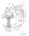
図1は、ギヤドモータ1の斜視図である。図2は、ギヤドモータの断面図である。本実施形態のギヤドモータ1は、Y軸方向に沿う寸法が抑制された薄型の電子機器に搭載される。 FIG. 1 is a perspective view of the gearedmotor 1. FIG. 2 is a cross-sectional view of the geared motor. The gearedmotor 1 of the present embodiment is mounted on a thin electronic device whose dimensions along the Y-axis direction are suppressed.

図2に示すように、ギヤドモータ1は、モータ2と、フレキシブル基板3と、ギヤ装置5と、フレーム10と、を有する。以下、ギヤドモータ1の各部について詳細に説明する。 As shown in FIG. 2, the gearedmotor 1 includes amotor 2, a flexible substrate 3, agear device 5, and aframe 10. Hereinafter, each part of the gearedmotor 1 will be described in detail.

<モータ>
モータ2は、例えばステッピングモータである。モータ2は、モータ軸線J1を中心とする略円柱状のモータ本体2aと、モータ本体2aの軸方向他方側の端部から延び出るモータシャフト2bと、ピニオンギヤ2cと、を有する。
<Motor>
Themotor 2 is, for example, a stepping motor. Themotor 2 has a substantiallycylindrical motor body 2a centered on the motor axis J1, amotor shaft 2b extending from the other end of themotor body 2a in the axial direction, and apinion gear 2c.

モータ本体2aの内部には、モータシャフト2bに繋がるロータとロータを囲むステータとが設けられる。モータ本体2aの外周面には、4つの端子2pが設けられる。4つの端子2pは、フレキシブル基板3に接続される。 Inside themotor body 2a, a rotor connected to themotor shaft 2b and a stator surrounding the rotor are provided. Fourterminals 2p are provided on the outer peripheral surface of themotor body 2a. The fourterminals 2p are connected to the flexible substrate 3.

モータシャフト2bは、モータ軸線J1を中心として軸方向に延びる。モータシャフト2bは、モータ軸線J1を中心として回転する。ピニオンギヤ2cは、モータシャフト2bに固定される。ピニオンギヤ2cは、ギヤ装置5のドライブギヤ機構20にモータ2の動力を伝達する。 Themotor shaft 2b extends in the axial direction about the motor axis J1. Themotor shaft 2b rotates about the motor axis J1. Thepinion gear 2c is fixed to themotor shaft 2b. Thepinion gear 2c transmits the power of themotor 2 to thedrive gear mechanism 20 of thegear device 5.

<ギヤ装置>
ギヤ装置5は、ドライブギヤ機構20と、中間ギヤ機構30と、出力ギヤ機構40と、を有する。ドライブギヤ機構20は、ドライブ軸線J2を中心として配置される。中間ギヤ機構30は、中間軸線J3を中心として配置される。出力ギヤ機構40は、出力軸線J4を中心として配置される。モータ軸線J1、ドライブ軸線J2、中間軸線J3および出力軸線J4は、互いに平行に延びる。すなわち、モータ軸線J1、ドライブ軸線J2および中間軸線J3は、出力軸線J4と平行である。モータ軸線J1、ドライブ軸線J2、中間軸線J3および出力軸線J4は、軸方向から見てX軸方向に直線状に並ぶ。
<Gear device>
Thegear device 5 includes adrive gear mechanism 20, anintermediate gear mechanism 30, and anoutput gear mechanism 40. Thedrive gear mechanism 20 is arranged around the drive axis J2. Theintermediate gear mechanism 30 is arranged around the intermediate axis J3. Theoutput gear mechanism 40 is arranged around the output axis J4. The motor axis J1, the drive axis J2, the intermediate axis J3, and the output axis J4 extend parallel to each other. That is, the motor axis J1, the drive axis J2, and the intermediate axis J3 are parallel to the output axis J4. The motor axis J1, the drive axis J2, the intermediate axis J3, and the output axis J4 are aligned linearly in the X-axis direction when viewed from the axial direction.

(ドライブギヤ機構)
ドライブギヤ機構20は、二段ギヤ部材23を有する。二段ギヤ部材23は、軸方向に沿って並んで配置される第1ギヤ21および第2ギヤ22を有する。第1ギヤ21および第2ギヤ22は、ともにドライブ軸線J2を中心とする。
(Drive gear mechanism)
Thedrive gear mechanism 20 has a two-stage gear member 23. The two-stage gear member 23 has afirst gear 21 and asecond gear 22 arranged side by side along the axial direction. Both thefirst gear 21 and thesecond gear 22 are centered on the drive axis J2.

二段ギヤ部材23には、ドライブ軸線J2に沿って軸方向に貫通する中央孔23aが設けられる。中央孔23aには、フレーム10からドライブ軸線J2を中心として延び出るドライブシャフト15が挿入される。これにより、二段ギヤ部材23は、ドライブ軸線J2を中心として回転可能にフレーム10に支持される。これにより、ドライブギヤ機構20の複数のギヤ(第1ギヤ21および第2ギヤ22)は、ドライブ軸線J2を中心として回転する。 The two-stage gear member 23 is provided with acentral hole 23a that penetrates in the axial direction along the drive axis J2. Adrive shaft 15 extending from theframe 10 about the drive axis J2 is inserted into thecentral hole 23a. As a result, the two-stage gear member 23 is rotatably supported by theframe 10 about the drive axis J2. As a result, the plurality of gears (first gear 21 and second gear 22) of thedrive gear mechanism 20 rotate about the drive axis J2.

第1ギヤ21は、ピニオンギヤ2cに噛み合う。これにより、第1ギヤ21は、モータ2から動力が伝達される。第2ギヤ22は、第1ギヤ21と単一の部材である。このため、第2ギヤ22は、第1ギヤ21とともに回転する。第2ギヤ22は、第1ギヤ21に対し軸方向一方側に位置する。第2ギヤ22は、第1ギヤ21より小径のギヤである。第2ギヤ22は、中間ギヤ機構30に接続される。ドライブギヤ機構20は、モータ2の動力を減速して中間ギヤ機構30に伝える。 Thefirst gear 21 meshes with thepinion gear 2c. As a result, power is transmitted from themotor 2 to thefirst gear 21. Thesecond gear 22 is a single member with thefirst gear 21. Therefore, thesecond gear 22 rotates together with thefirst gear 21. Thesecond gear 22 is located on one side in the axial direction with respect to thefirst gear 21. Thesecond gear 22 is a gear having a smaller diameter than thefirst gear 21. Thesecond gear 22 is connected to theintermediate gear mechanism 30. Thedrive gear mechanism 20 decelerates the power of themotor 2 and transmits it to theintermediate gear mechanism 30.

(中間ギヤ機構)
中間ギヤ機構30は、中間軸線J3周りを回転する複数のギヤを有する。中間ギヤ機構30の複数のギヤは、カウンタギヤ31および中間ギヤ39を含む。また、中間ギヤ機構30は、軸方向においてカウンタギヤ31と中間ギヤ39との間に配置される遊星歯車機構32を有する。カウンタギヤ31は、遊星歯車機構32の軸方向他方側に接続される。一方で中間ギヤ39は、遊星歯車機構32の軸方向一方側に接続される。
(Intermediate gear mechanism)
Theintermediate gear mechanism 30 has a plurality of gears that rotate around the intermediate axis J3. The plurality of gears of theintermediate gear mechanism 30 include acounter gear 31 and anintermediate gear 39. Further, theintermediate gear mechanism 30 has aplanetary gear mechanism 32 arranged between thecounter gear 31 and theintermediate gear 39 in the axial direction. Thecounter gear 31 is connected to the other side of theplanetary gear mechanism 32 in the axial direction. On the other hand, theintermediate gear 39 is connected to one side in the axial direction of theplanetary gear mechanism 32.

カウンタギヤ31は、中間軸線J3を中心とする。カウンタギヤ31は、ドライブギヤ機構20の第2ギヤ22に噛み合う。カウンタギヤ31には、中間軸線J3に沿って軸方向に貫通する中央孔31aが設けられる。中央孔31aには、フレーム10から中間軸線J3を中心として延び出る中間シャフト16が挿入される。これにより、カウンタギヤ31は、中間軸線J3を中心として回転可能にフレーム10に支持される。 Thecounter gear 31 is centered on the intermediate axis J3. Thecounter gear 31 meshes with thesecond gear 22 of thedrive gear mechanism 20. Thecounter gear 31 is provided with a central hole 31a that penetrates in the axial direction along the intermediate axis J3. Anintermediate shaft 16 extending from theframe 10 about the intermediate axis J3 is inserted into the central hole 31a. As a result, thecounter gear 31 is rotatably supported by theframe 10 about the intermediate axis J3.

遊星歯車機構32は、第1太陽ギヤ33aと、3つの第1遊星ギヤ33bと、第1キャリア33cと、第2太陽ギヤ34aと、3つの第2遊星ギヤ34bと、第2キャリア34cと、インターナルギヤ35と、を有する。 Theplanetary gear mechanism 32 includes a first sun gear 33a, three first planet gears 33b, afirst carrier 33c, a second sun gear 34a, three second planet gears 34b, and asecond carrier 34c. It has aninternal gear 35 and.

インターナルギヤ35は、中間軸線J3を中心として軸方向に延びる筒状である。インターナルギヤ35は、内周面に設けられたギヤにおいて第1遊星ギヤ33bおよび第2遊星ギヤ34bに噛み合う。インターナルギヤ35は、フレーム10に固定されており回転しない。 Theinternal gear 35 has a tubular shape extending in the axial direction about the intermediate axis J3. Theinternal gear 35 meshes with the first planetary gear 33b and the secondplanetary gear 34b in a gear provided on the inner peripheral surface. Theinternal gear 35 is fixed to theframe 10 and does not rotate.

第1太陽ギヤ33aは、カウンタギヤ31に連結される。第1太陽ギヤ33aは、カウンタギヤ31より小径のギヤである。第1太陽ギヤ33aは、カウンタギヤ31とともに中間軸線J3を中心として回転する。 The first sun gear 33a is connected to thecounter gear 31. The first sun gear 33a is a gear having a smaller diameter than thecounter gear 31. The first sun gear 33a rotates about the intermediate axis J3 together with thecounter gear 31.

3つの第1遊星ギヤ33bは、中間軸線J3の周方向に等間隔に配置される。3つの第1遊星ギヤ33bは、第1太陽ギヤ33aに噛み合う。3つの第1遊星ギヤ33bは、第1太陽ギヤ33aの回転に伴い、中間軸線J3の周方向に公転回転する。第1遊星ギヤ33bの中央には、貫通孔33baが設けられる。 The three first planetary gears 33b are arranged at equal intervals in the circumferential direction of the intermediate axis J3. The three first planetary gears 33b mesh with the first sun gear 33a. The three first planetary gears 33b revolve in the circumferential direction of the intermediate axis J3 as the first sun gear 33a rotates. A through hole 33ba is provided in the center of the first planetary gear 33b.

第1キャリア33cは、円盤部33cbと、3本の第1サブシャフト33caと、第1メインシャフト33ccと、を有する。円盤部33cbは、中間軸線J3を中心として径方向に延びる。3本の第1サブシャフト33caは、円盤部33cbから軸方向他方側に延びる。3本の第1サブシャフト33caは、それぞれ第1遊星ギヤ33bの貫通孔33baに挿入される。これにより、第1キャリア33cは、第1サブシャフト33caにおいて第1遊星ギヤ33bを回転可能に支持する。3つの第1遊星ギヤ33bの中間軸線J3を中心とする公転回転に伴い、第1キャリア33cは、中間軸線J3を中心として回転する。第1メインシャフト33ccは、中間軸線J3を中心として円盤部33cbから軸方向一方側に延びる。 Thefirst carrier 33c has a disk portion 33cc, three first sub-shafts 33ca, and a first main shaft 33cc. The disk portion 33cc extends in the radial direction about the intermediate axis J3. The three first sub-shafts 33ca extend from the disk portion 33cc to the other side in the axial direction. The three first sub-shafts 33ca are each inserted into the through holes 33ba of the first planetary gear 33b. As a result, thefirst carrier 33c rotatably supports the first planetary gear 33b on the first sub-shaft 33ca. Thefirst carrier 33c rotates about the intermediate axis J3 as the three first planetary gears 33b revolve around the intermediate axis J3. The first main shaft 33cc extends from the disk portion 33cc to one side in the axial direction about the intermediate axis J3.

第2太陽ギヤ34aは、第1メインシャフト33ccの外周面に設けられる。第2太陽ギヤ34aは、第1メインシャフト33ccとともに中間軸線J3を中心として回転する。 The second sun gear 34a is provided on the outer peripheral surface of the first main shaft 33cc. The second sun gear 34a rotates about the intermediate axis J3 together with the first main shaft 33cc.

3つの第2遊星ギヤ34bは、中間軸線J3の周方向に等間隔に配置される。3つの第2遊星ギヤ34bは、第2太陽ギヤ34aに噛み合う。3つの第2遊星ギヤ34bは、第2太陽ギヤ34aの回転に伴い、中間軸線J3の周方向に公転回転する。第2遊星ギヤ34bの中央には、貫通孔34baが設けられる。 The three secondplanetary gears 34b are arranged at equal intervals in the circumferential direction of the intermediate axis J3. The three secondplanetary gears 34b mesh with the second sun gear 34a. The three secondplanetary gears 34b revolve in the circumferential direction of the intermediate axis J3 as the second sun gear 34a rotates. A through hole 34ba is provided in the center of the secondplanetary gear 34b.

第2キャリア34cは、円盤部34cbと、3本の第2サブシャフト34caと、第2メインシャフト34ccと、を有する。円盤部34cbは、中間軸線J3を中心として径方向に延びる。3本の第2サブシャフト34caは、円盤部34cbから軸方向他方側に延びる。3本の第2サブシャフト34caは、それぞれ第2遊星ギヤ34bの貫通孔34baに挿入される。これにより、第2キャリア34cは、第2サブシャフト34caにおいて第2遊星ギヤ34bを回転可能に支持する。3つの第2遊星ギヤ34bの中間軸線J3を中心とする公転回転に伴い、第2キャリア34cは、中間軸線J3を中心として回転する。第2メインシャフト34ccは、中間軸線J3を中心として円盤部34cbから軸方向一方側に延びる。また、第2メインシャフト34ccの軸方向一方側の先端は、フレーム10により回転可能に支持される。 Thesecond carrier 34c has a disk portion 34cc, three second sub-shafts 34ca, and a second main shaft 34cc. The disk portion 34cc extends in the radial direction about the intermediate axis J3. The three second sub-shafts 34ca extend from the disk portion 34cc to the other side in the axial direction. The three second subshafts 34ca are each inserted into the through holes 34ba of the secondplanetary gear 34b. As a result, thesecond carrier 34c rotatably supports the secondplanetary gear 34b on the second subshaft 34ca. Thesecond carrier 34c rotates about the intermediate axis J3 as the three secondplanetary gears 34b revolve around the intermediate axis J3. The second main shaft 34cc extends from the disk portion 34cc to one side in the axial direction about the intermediate axis J3. Further, the tip of the second main shaft 34cc on one side in the axial direction is rotatably supported by theframe 10.

中間ギヤ39は、第2メインシャフト34ccの外周面に設けられる。中間ギヤ39は、第2メインシャフト34ccとともに中間軸線J3を中心として回転する。中間ギヤ39は、出力ギヤ機構40に接続される。 Theintermediate gear 39 is provided on the outer peripheral surface of the second main shaft 34cc. Theintermediate gear 39 rotates about the intermediate axis J3 together with the second main shaft 34cc. Theintermediate gear 39 is connected to theoutput gear mechanism 40.

本実施形態の中間ギヤ機構30は、軸方向他方側の端部のカウンタギヤ31に伝わったモータ2の動力を軸方向一方側の端部の中間ギヤ39において、出力ギヤ機構40に伝える。中間ギヤ機構30は、中間軸線J3周りに回転する遊星歯車機構32を有する。このため、中間ギヤ機構30は、モータ2の動力を伝達する過程で、動力を減速して出力ギヤ機構40に伝える。また、本実施形態の遊星歯車機構32は、2種の太陽ギヤおよび遊星ギヤを有し2段階に減速される。このため、本実施形態の中間ギヤ機構30によれば、大減速比を実現できる。 Theintermediate gear mechanism 30 of the present embodiment transmits the power of themotor 2 transmitted to thecounter gear 31 at the other end in the axial direction to theoutput gear mechanism 40 at theintermediate gear 39 at the end on the other side in the axial direction. Theintermediate gear mechanism 30 has aplanetary gear mechanism 32 that rotates around the intermediate axis J3. Therefore, theintermediate gear mechanism 30 decelerates the power and transmits the power to theoutput gear mechanism 40 in the process of transmitting the power of themotor 2. Further, theplanetary gear mechanism 32 of the present embodiment has two types of sun gears and planetary gears, and is decelerated in two stages. Therefore, according to theintermediate gear mechanism 30 of the present embodiment, a large reduction ratio can be realized.

(出力ギヤ機構)
出力ギヤ機構40は、出力シャフト44と、フランジ部45と、ギヤセット43と、コイルバネ(弾性部材)46と、一対のボールベアリング49A、49Bと、を有する。フランジ部45と、ギヤセット43と、コイルバネ46とは、軸方向一方側から他方側に向かってこの順で配置される。フランジ部45は、出力シャフト44に固定される。コイルバネ46は、ギヤセット43をフランジ部45側に押し付ける。
(Output gear mechanism)
Theoutput gear mechanism 40 includes anoutput shaft 44, aflange portion 45, a gear set 43, a coil spring (elastic member) 46, and a pair ofball bearings 49A and 49B. Theflange portion 45, the gear set 43, and thecoil spring 46 are arranged in this order from one side in the axial direction to the other side. Theflange portion 45 is fixed to theoutput shaft 44. Thecoil spring 46 presses the gear set 43 against theflange portion 45.

出力シャフト44は、出力軸線J4に沿って延びる。出力シャフト44は、軸方向一方側に位置する第1端部44aと、軸方向他方側に位置する第2端部44bとを有する。出力シャフト44の両端部(第1端部44aおよび第2端部44b)は、それぞれボールベアリング49A、49Bにより出力軸線J4周りに回転可能に支持される。一対のボールベアリング49A、49Bは、フレーム10に保持される。なお、以下の説明において、一対のボールベアリング49A、49Bのうち、第1端部44aを支持する一方を第1ボールベアリング49Aと呼び、第2端部44bを支持する他方を第2ボールベアリング49Bと呼ぶ。 Theoutput shaft 44 extends along the output axis J4. Theoutput shaft 44 has afirst end portion 44a located on one side in the axial direction and asecond end portion 44b located on the other side in the axial direction. Both ends (first end 44a andsecond end 44b) of theoutput shaft 44 are rotatably supported around the output axis J4 byball bearings 49A and 49B, respectively. The pair ofball bearings 49A and 49B are held by theframe 10. In the following description, of the pair ofball bearings 49A and 49B, one that supports thefirst end portion 44a is referred to as a first ball bearing 49A, and the other that supports thesecond end portion 44b is referred to as a second ball bearing 49B. Called.

出力シャフト44の外周面には、径方向外側に延びるフランジ部45が設けられる。フランジ部45は、出力シャフト44共に出力軸線J4周りに回転する。本実施形態において、出力シャフト44とフランジ部45とは単一の部材である。しかしながら、出力シャフト44とフランジ部45とは、互いに固定されていれば別部材であってもよい。 Aflange portion 45 extending radially outward is provided on the outer peripheral surface of theoutput shaft 44. Theflange portion 45 rotates around the output axis J4 together with theoutput shaft 44. In the present embodiment, theoutput shaft 44 and theflange portion 45 are a single member. However, theoutput shaft 44 and theflange portion 45 may be separate members as long as they are fixed to each other.

フランジ部45は、ギヤセット43の軸方向一方側に位置する。フランジ部45は、出力軸線J4を中心とする円形である。フランジ部45は、軸方向一方側を向く第1対向面45aと、軸方向他方側を向く第2対向面45fを有する。 Theflange portion 45 is located on one side of the gear set 43 in the axial direction. Theflange portion 45 has a circular shape centered on the output axis J4. Theflange portion 45 has a first facingsurface 45a facing one side in the axial direction and a second facingsurface 45f facing the other side in the axial direction.

第1対向面45aは、出力軸線J4に直交する平坦面である。第1対向面45aは、第1ボールベアリング49Aと軸方向に対向する。第1対向面45aは、第1ボールベアリング49Aの内輪と接触する。 The first facingsurface 45a is a flat surface orthogonal to the output axis J4. The first facingsurface 45a faces the first ball bearing 49A in the axial direction. The first facingsurface 45a comes into contact with the inner ring of the first ball bearing 49A.

図3は、出力ギヤ機構40の一部を拡大した正面図である。
第2対向面45fは、ギヤセット43と軸方向に対向する。第2対向面45fには、軸方向他方側に突出し周方向に沿って並ぶ複数の第1山部45bが設けられる。
FIG. 3 is an enlarged front view of a part of theoutput gear mechanism 40.
The second facingsurface 45f faces the gear set 43 in the axial direction. The second facingsurface 45f is provided with a plurality offirst mountain portions 45b that project to the other side in the axial direction and are lined up along the circumferential direction.

第1山部45bは、第1頂面部45baと、第1頂面部45baの周方向の両側に位置する一対の第1傾斜側部45bbと、を有する。第1頂面部45baは、軸線と直交する平面状である。第1傾斜側部45bbは、第1頂面部45baから周方向に離れる従い軸方向一方側に傾斜する。本実施形態において、第1傾斜側部45bbは、軸方向に対して45°で傾斜する。 Thefirst mountain portion 45b has a first top surface portion 45ba and a pair of first inclined side portions 45bb located on both sides of the first top surface portion 45ba in the circumferential direction. The first top surface portion 45ba has a planar shape orthogonal to the axis. The first inclined side portion 45bb is inclined to one side in the axial direction, which is separated from the first top surface portion 45ba in the circumferential direction. In the present embodiment, the first inclined side portion 45bb is inclined at 45 ° with respect to the axial direction.

周方向に沿って並ぶ第1山部45b同士の間には第1谷部45cが設けられる。第1谷部45cは、第1山部45b同士の間の空間である。第1谷部45cは、軸方向他方側を向く第1底面部45caを有する。フランジ部45の第2対向面45fは、周方向に沿って第1頂面部45ba、第1傾斜側部45bb、第1底面部45caおよび第1傾斜側部45bbが交互に並ぶ波状の面である。 Afirst valley portion 45c is provided between thefirst peak portions 45b arranged along the circumferential direction. Thefirst valley portion 45c is a space between thefirst mountain portions 45b. Thefirst valley portion 45c has a first bottom surface portion 45ca facing the other side in the axial direction. The second facingsurface 45f of theflange portion 45 is a wavy surface in which the first top surface portion 45ba, the first inclined side portion 45bb, the first bottom surface portion 45ca, and the first inclined side portion 45bb are alternately arranged along the circumferential direction. ..

図2に示すように、ギヤセット43は、一対のギヤ(メインギヤ41およびサブギヤ42)を有する。メインギヤ41とサブギヤ42とは、互いに別部材である。メインギヤ41とサブギヤ42とは、軸方向に沿って並ぶ。サブギヤ42は、メインギヤ41より歯数が多い。すなわち、ギヤセット43は、一方が他方より歯数が多い一対のギヤ(メインギヤ41およびサブギヤ42)を有する。メインギヤ41およびサブギヤ42は、それぞれ中間ギヤ39に噛み合う。すなわち、ギヤセット43は、中間ギヤ39に噛み合う。中間ギヤ39は、ギヤセット43に動力を伝える。 As shown in FIG. 2, the gear set 43 has a pair of gears (main gear 41 and sub gear 42). Themain gear 41 and thesub gear 42 are separate members from each other. Themain gear 41 and thesub gear 42 are arranged along the axial direction. Thesub gear 42 has more teeth than themain gear 41. That is, the gear set 43 has a pair of gears (main gear 41 and sub gear 42) on which one has more teeth than the other. Themain gear 41 and thesub gear 42 mesh with theintermediate gear 39, respectively. That is, the gear set 43 meshes with theintermediate gear 39. Theintermediate gear 39 transmits power to the gear set 43.

メインギヤ41には、軸方向に貫通する貫通孔41hが設けられ、サブギヤ42には、軸方向に貫通する貫通孔42hが設けられる。メインギヤ41およびサブギヤ42の貫通孔41h、42hは、直径が略等しい円形である。メインギヤ41の貫通孔41hおよびサブギヤ42の貫通孔42hには、出力シャフト44が挿通される。メインギヤ41およびサブギヤ42の貫通孔41h、42hの直径は、出力シャフト44の貫通孔41h、42hに挿通される部分の外径より若干大きい。したがって、メインギヤ41およびサブギヤ42は、出力シャフト44に対し回転方向および軸方向に移動可能である。すなわち、ギヤセット43は、出力シャフト44に回転方向および軸方向へ移動可能に支持される。また、メインギヤ41とサブギヤ42とは、互いに相対回転可能である。 Themain gear 41 is provided with a throughhole 41h penetrating in the axial direction, and thesub gear 42 is provided with a throughhole 42h penetrating in the axial direction. The throughholes 41h and 42h of themain gear 41 and thesub gear 42 have circular shapes having substantially the same diameter. Theoutput shaft 44 is inserted through the throughhole 41h of themain gear 41 and the throughhole 42h of thesub gear 42. The diameters of the throughholes 41h and 42h of themain gear 41 and thesub gear 42 are slightly larger than the outer diameter of the portion inserted through the throughholes 41h and 42h of theoutput shaft 44. Therefore, themain gear 41 and thesub gear 42 can move in the rotational direction and the axial direction with respect to theoutput shaft 44. That is, the gear set 43 is movably supported by theoutput shaft 44 in the rotational and axial directions. Further, themain gear 41 and thesub gear 42 can rotate relative to each other.

メインギヤ41は、サブギヤ42の軸方向一方側に位置する。メインギヤ41は、サブギヤ42より歯幅(歯の軸方向に沿う寸法)が大きい。 Themain gear 41 is located on one side of thesub gear 42 in the axial direction. Themain gear 41 has a larger tooth width (dimension along the axial direction of the teeth) than thesub gear 42.

メインギヤ41は、軸方向一方側を向く第3対向面41aと、軸方向他方側を向く第4対向面41fと、を有する。第3対向面41aは、軸方向においてフランジ部45に対向し接触する。一方で、第4対向面41fは、軸方向においてサブギヤ42に対向し接触する。 Themain gear 41 has a third facingsurface 41a facing one side in the axial direction and a fourth facingsurface 41f facing the other side in the axial direction. The third facingsurface 41a faces and contacts theflange portion 45 in the axial direction. On the other hand, the fourth facingsurface 41f faces and contacts thesub gear 42 in the axial direction.

図3に示すように、メインギヤ41の第3対向面41aには、フランジ部45の第2対向面45fと同様の周方向に延びる波状の面が設けられる。すなわち、第3対向面41aには、軸方向一方側に突出し周方向に沿って並ぶ複数の第2山部41bが設けられる。 As shown in FIG. 3, the third facingsurface 41a of themain gear 41 is provided with a wavy surface extending in the circumferential direction similar to the second facingsurface 45f of theflange portion 45. That is, the third facingsurface 41a is provided with a plurality ofsecond mountain portions 41b that project to one side in the axial direction and are lined up along the circumferential direction.

第2山部41bは、第2頂面部41baと、第2頂面部41baの周方向の両側に位置する一対の第2傾斜側部41bbと、を有する。第2頂面部41baは、軸線と直交する平面状である。第2傾斜側部41bbは、第2頂面部41baから周方向に離れる従い軸方向他方側に傾斜する。本実施形態において、第2傾斜側部41bbは、軸方向に対して45°で傾斜する。周方向に沿って並ぶ第2山部41b同士の間には第2谷部41cが設けられる。第2谷部41cは、軸方向一方側を向く第2底面部41caを有する。 Thesecond mountain portion 41b has a second top surface portion 41ba and a pair of second inclined side portions 41bb located on both sides of the second top surface portion 41ba in the circumferential direction. The second top surface portion 41ba has a planar shape orthogonal to the axis. The second inclined side portion 41bb is inclined to the other side in the axial direction, which is separated from the second top surface portion 41ba in the circumferential direction. In the present embodiment, the second inclined side portion 41bb is inclined at 45 ° with respect to the axial direction. Asecond valley portion 41c is provided between thesecond peak portions 41b arranged along the circumferential direction. Thesecond valley portion 41c has a second bottom surface portion 41ca that faces one side in the axial direction.

メインギヤ41の第3対向面41aの第2山部41bおよび第2谷部41cは、フランジ部45の第2対向面45fの第1山部45bおよび第1谷部45cに噛み合う。より具体的には、第2山部41bが、第1谷部45cに嵌り、第1山部45bが第2谷部41cに嵌る。これに伴い、第2傾斜側部41bbと第1傾斜側部45bbとが互いに接触する。 Thesecond peak portion 41b and thesecond valley portion 41c of the third facingsurface 41a of themain gear 41 mesh with thefirst peak portion 45b and thefirst valley portion 45c of the second facingsurface 45f of theflange portion 45. More specifically, thesecond mountain portion 41b fits into thefirst valley portion 45c, and thefirst mountain portion 45b fits into thesecond valley portion 41c. Along with this, the second inclined side portion 41bb and the first inclined side portion 45bb come into contact with each other.

フランジ部45とギヤセット43の山部45b、41bおよび谷部45c、41cが、軸方向に互いに噛み合うことで、ギヤセット43とフランジ部45とが同期回転する。これにより、ギヤセット43に伝わった動力が、フランジ部45を介して出力シャフト44に伝わる。 Theflange portion 45 and thepeak portions 45b and 41b and thevalley portions 45c and 41c of the gear set 43 mesh with each other in the axial direction, so that the gear set 43 and theflange portion 45 rotate synchronously. As a result, the power transmitted to the gear set 43 is transmitted to theoutput shaft 44 via theflange portion 45.

上述したように、ギヤセット43はコイルバネ46によってフランジ部45に押し付けられる。このため、ギヤセット43の回転時に、山部45b、41bおよび谷部45c、41cの噛み合いが維持されて、ギヤセット43の回転がフランジ部45に伝わる。一方で、第1傾斜側部45bbと第2傾斜側部41bbとの間に付与される反力が大きくなり一定の値を超えると、第1傾斜側部45bbと第2傾斜側部41bbとが互いに滑りギヤセット43とフランジ部45との間の動力伝達が切断される。 As described above, the gear set 43 is pressed against theflange portion 45 by thecoil spring 46. Therefore, when the gear set 43 rotates, the meshing of thepeaks 45b and 41b and thevalleys 45c and 41c is maintained, and the rotation of the gear set 43 is transmitted to theflange 45. On the other hand, when the reaction force applied between the first inclined side portion 45bb and the second inclined side portion 41bb becomes large and exceeds a certain value, the first inclined side portion 45bb and the second inclined side portion 41bb become The power transmission between the sliding gear set 43 and theflange portion 45 is cut off from each other.

本実施形態によれば、フランジ部45およびギヤセット43の山部45b、41bおよび谷部45c、41cは、コイルバネ46によって押し付けられて、トルクリミッタとして機能する。トルクリミッタ機能が働く場合としては、例えば、出力シャフト44がロックしたままモータが駆動する場合、出力シャフト44側からギヤセット43側に過度な回転力が付与される場合などが考えられる。本実施形態によれば、出力ギヤ機構40に過大な負荷が作用した場合であってもトルクリミッタ機能によって動力の伝達が切断されることで、モータ2から中間ギヤ機構30への動力伝達経路の各部に過大な負荷が加わることを抑制でき、各部の損傷を抑止できる。
なお、本実施形態では、互いに向かい合う第1傾斜側部45bbと第2傾斜側部41bbとは出力軸線J4に対して互いに反対方向に45°に傾斜する。これらの角度を共に大きくすることで、トルクリミッタ機能において制限されるトルクの閾値を大きくすることができる。
According to the present embodiment, theridges 45b, 41b and thevalleys 45c, 41c of theflange portion 45 and the gear set 43 are pressed by thecoil spring 46 to function as a torque limiter. As a case where the torque limiter function works, for example, when the motor is driven while theoutput shaft 44 is locked, an excessive rotational force is applied from theoutput shaft 44 side to the gear set 43 side. According to the present embodiment, even when an excessive load is applied to theoutput gear mechanism 40, the power transmission is cut off by the torque limiter function, so that the power transmission path from themotor 2 to theintermediate gear mechanism 30 It is possible to suppress an excessive load applied to each part and prevent damage to each part.
In the present embodiment, the first inclined side portion 45bb and the second inclined side portion 41bb facing each other are inclined at 45 ° in opposite directions with respect to the output axis J4. By increasing both of these angles, it is possible to increase the torque threshold value limited by the torque limiter function.

図2に示すように、サブギヤ42は、メインギヤ41の軸方向他方側に位置する。サブギヤ42は、軸方向一方側を向く第5対向面42aと、軸方向他方側を向く第6対向面42fと、を有する。第5対向面42aは、軸方向においてメインギヤ41に対向し接触する。一方で、第6対向面42fは、軸方向においてコイルバネ46の軸方向一方側の端部に接触する。 As shown in FIG. 2, thesub gear 42 is located on the other side of themain gear 41 in the axial direction. Thesub gear 42 has a fifth facingsurface 42a facing one side in the axial direction and a sixth facingsurface 42f facing the other side in the axial direction. The fifth facingsurface 42a faces and contacts themain gear 41 in the axial direction. On the other hand, the sixth facingsurface 42f contacts the end portion of thecoil spring 46 on one side in the axial direction in the axial direction.

サブギヤ42の第5対向面42aおよびメインギヤ41の第4対向面41fは、ともに出力軸線J4に直交する平坦面である。第4対向面41fと第5対向面42aとは、互いに接触してコイルバネ46によって面圧が付与される。すなわち、サブギヤ42とメインギヤ41とは、互いに向き合う面で面接触する。 The fifth facingsurface 42a of thesub gear 42 and the fourth facingsurface 41f of themain gear 41 are both flat surfaces orthogonal to the output axis J4. The fourth facingsurface 41f and the fifth facingsurface 42a are in contact with each other, and surface pressure is applied by thecoil spring 46. That is, thesub gear 42 and themain gear 41 come into surface contact with each other on the surfaces facing each other.

図4は、ギヤセット43と中間ギヤ39との噛み合いの様子を示す断面図である。図4において、ギヤセット43の回転方向T1および中間ギヤの回転方向T2を図示する。本実施形態において、サブギヤ42の歯数は、メインギヤ41の歯数より1つだけ多い。 FIG. 4 is a cross-sectional view showing how the gear set 43 and theintermediate gear 39 are engaged with each other. In FIG. 4, the rotation direction T1 of the gear set 43 and the rotation direction T2 of the intermediate gear are illustrated. In the present embodiment, the number of teeth of thesub gear 42 is one more than the number of teeth of themain gear 41.

メインギヤ41は、中間ギヤ39に噛み合って中間ギヤ39の回転に伴い出力軸線J4周りに回転する。この時、メインギヤ41は、回転方向T1を向く歯面で、中間ギヤ39に接触する。一方で、サブギヤ42の歯数がメインギヤ41の歯数より多いため、サブギヤ42の回転速度がメインギヤ41の回転より遅くなる。すなわち、中間ギヤ39とサブギヤ42とは、その歯数差ために回転速度差が生じる。また、サブギヤ42は、コイルバネ46によりメインギヤ41に押し付けらえて第4対向面41fと第5対向面42aとの間には、摩擦力が発生する。そして、この摩擦力と回転差のために中間ギヤ39は、回転方向T1の反対側を向く歯面で、中間ギヤ39に接触する。結果的に、中間ギヤ39とギヤセット43との間にバックラッシュが除去される。すなわち、ギヤセット43は、バックラッシュ除去機能を有する。 Themain gear 41 meshes with theintermediate gear 39 and rotates around the output axis J4 as theintermediate gear 39 rotates. At this time, themain gear 41 comes into contact with theintermediate gear 39 on the tooth surface facing the rotation direction T1. On the other hand, since the number of teeth of thesub gear 42 is larger than the number of teeth of themain gear 41, the rotation speed of thesub gear 42 is slower than that of themain gear 41. That is, a difference in rotational speed occurs between theintermediate gear 39 and thesub gear 42 due to the difference in the number of teeth. Further, thesub gear 42 is pressed against themain gear 41 by thecoil spring 46, and a frictional force is generated between the fourth facingsurface 41f and the fifth facingsurface 42a. Then, due to this frictional force and the difference in rotation, theintermediate gear 39 comes into contact with theintermediate gear 39 on the tooth surface facing the opposite side in the rotation direction T1. As a result, backlash is removed between theintermediate gear 39 and the gear set 43. That is, the gear set 43 has a backlash removing function.

図2に示すように、コイルバネ46は、ギヤセット43の軸方向他方側に位置する。コイルバネ46の内径部には、出力シャフト44が通される。コイルバネ46は、ギヤセット43をフランジ部45側に押し付ける。なお、本実施形態では、ギヤセット43をフランジ部45側に押し付ける弾性部材としてコイルバネを採用する例について説明するが、板バネや皿バネ等のそのほかのバネであってもよく、またゴムやエラストマ樹脂等であってもよい。 As shown in FIG. 2, thecoil spring 46 is located on the other side of the gear set 43 in the axial direction. Theoutput shaft 44 is passed through the inner diameter of thecoil spring 46. Thecoil spring 46 presses the gear set 43 against theflange portion 45. In this embodiment, an example in which a coil spring is used as an elastic member for pressing the gear set 43 against theflange portion 45 side will be described, but other springs such as leaf springs and disc springs may be used, and rubber or elastomer resin may be used. And so on.

コイルバネ46は、コイルバネ本体47と、コイルバネ本体47の両端部に取り付けられる一対のブッシュ部材48と、を有する。 Thecoil spring 46 has a coil springmain body 47 and a pair ofbush members 48 attached to both ends of the coil springmain body 47.

ブッシュ部材は48、コイルバネ本体47の内径部に嵌るブッシュ筒部と、ブッシュ筒部の一端から径方向外側に延びるブッシュフランジと、を有する。一対のブッシュ部材48のうち軸方向一方側に位置する一方は、ブッシュフランジにおいて、サブギヤ42の第6対向面42fに接触する。また、一対のブッシュ部材48のうち軸方向他方側に位置する他方は、ブッシュフランジにおいて、第2ボールベアリング49Bの内輪に接触する。 The bush member includes 48, a bush cylinder portion that fits into the inner diameter portion of thecoil spring body 47, and a bush flange that extends radially outward from one end of the bush cylinder portion. One of the pair ofbush members 48 located on one side in the axial direction comes into contact with the sixth facingsurface 42f of thesub gear 42 at the bush flange. Further, the other of the pair ofbush members 48 located on the other side in the axial direction comes into contact with the inner ring of the second ball bearing 49B at the bush flange.

コイルバネ46は、コイルバネ本体47を圧縮した状態でギヤセット43と第2ボールベアリング49Bの内輪との間に挟み込まれる。これにより、ギヤセット43を軸方向一方側に押し付けるとともに、第2ボールベアリング49Bの内輪を軸方向他方側に押し付ける。 Thecoil spring 46 is sandwiched between the gear set 43 and the inner ring of the second ball bearing 49B in a compressed state of thecoil spring body 47. As a result, the gear set 43 is pressed to one side in the axial direction, and the inner ring of the second ball bearing 49B is pressed to the other side in the axial direction.

コイルバネ46は、メインギヤ41およびフランジ部45の山部41b、45bを谷部41c、45cに押し付けるとともにメインギヤ41とサブギヤ42との間に面圧を付与する。すなわち、コイルバネ46の圧縮力は、トルクリミッタ機能およびバックラッシュ除去機能に利用される。本実施形態によれば、1つのコイルバネ46を用いて、トルクリミッタ機能およびバックラッシュ除去機能を得ることができ、部品点数を抑制しコスト削減を図るとともに、ギヤ装置5の小型化を図ることができる。 Thecoil spring 46 presses thepeaks 41b and 45b of themain gear 41 and theflange 45 against thevalleys 41c and 45c, and applies surface pressure between themain gear 41 and thesub gear 42. That is, the compressive force of thecoil spring 46 is used for the torque limiter function and the backlash removing function. According to the present embodiment, onecoil spring 46 can be used to obtain a torque limiter function and a backlash removing function, and it is possible to reduce the number of parts, reduce costs, and reduce the size of thegear device 5. it can.

本実施形態によれば、コイルバネ46は、出力シャフト44をフレーム10に対して軸方向の一方側に押し付ける。したがって、コイルバネ46は、出力シャフト44の軸方向のガタを除去することができる。 According to this embodiment, thecoil spring 46 presses theoutput shaft 44 against theframe 10 on one side in the axial direction. Therefore, thecoil spring 46 can remove the backlash in the axial direction of theoutput shaft 44.

本実施形態では、出力シャフト44の両端部が、第1ボールベアリング49Aおよび第2ボールベアリング49Bによって支持される。また、コイルバネ46は、第1ボールベアリング49Aの内輪を、ギヤセット43を介し、軸方向一方側に押し付ける。コイルバネ46は、第2ボールベアリング49Bの内輪を、軸方向他方側に押し付ける。すなわち、コイルバネ46は、一対のボールベアリング49A、49Bの内輪を互いに離間する方向に押し付けて予圧を付与し、ボールベアリング49A、49Bに円滑な回転を実現させる。 In the present embodiment, both ends of theoutput shaft 44 are supported by the first ball bearing 49A and the second ball bearing 49B. Further, thecoil spring 46 presses the inner ring of the first ball bearing 49A to one side in the axial direction via the gear set 43. Thecoil spring 46 presses the inner ring of the second ball bearing 49B to the other side in the axial direction. That is, thecoil spring 46 presses the inner rings of the pair ofball bearings 49A and 49B in the directions away from each other to apply a preload, and makes theball bearings 49A and 49B realize smooth rotation.

<フレーム>
図1に示すように、フレーム10は、第1フレーム部材11と第2フレーム部材12とを有する。第1フレーム部材11および第2フレーム部材12は、例えば、金属粉末射出成形(MIM)によって成型される。第1フレーム部材11および第2フレーム部材12は、モータ本体2aに固定される。第1フレーム部材11は、モータ2に対し軸方向一方側に位置する。一方で、第2フレーム部材12は、モータ2に対し軸方向他方側に位置する。
<Frame>
As shown in FIG. 1, theframe 10 has afirst frame member 11 and asecond frame member 12. Thefirst frame member 11 and thesecond frame member 12 are molded by, for example, metal powder injection molding (MIM). Thefirst frame member 11 and thesecond frame member 12 are fixed to themotor body 2a. Thefirst frame member 11 is located on one side in the axial direction with respect to themotor 2. On the other hand, thesecond frame member 12 is located on the other side in the axial direction with respect to themotor 2.

第1フレーム部材11は、モータ支持部11aと、中間ギヤ機構支持部11bと、第1出力シャフト支持部11cと、固定部13と、を有する。 Thefirst frame member 11 includes amotor support portion 11a, an intermediate gearmechanism support portion 11b, a first outputshaft support portion 11c, and a fixingportion 13.

モータ支持部11aは、モータ本体2aの軸方向一方側の端部を覆う円盤状である。モータ支持部11aとモータ本体2aとの境界部には、溶接部9が設けられる。これにより、第1フレーム部材11は、溶接部9において、モータ本体2aに溶接固定される。より具体的には、第1フレーム部材11は、モータ本体2aの軸方向一方側の端部に溶接固定される。 Themotor support portion 11a has a disk shape that covers one end of themotor body 2a in the axial direction. A weldedportion 9 is provided at the boundary between themotor support portion 11a and the motormain body 2a. As a result, thefirst frame member 11 is welded and fixed to themotor body 2a at the weldedportion 9. More specifically, thefirst frame member 11 is welded and fixed to one end of themotor body 2a on one side in the axial direction.

中間ギヤ機構支持部11bは、中間ギヤ機構30の軸方向一方側に位置する。中間ギヤ機構支持部11bは、筒部11baと、筒部11baの軸方向一方側の端部に位置する底部11bbと、を有する。 The intermediate gearmechanism support portion 11b is located on one side in the axial direction of theintermediate gear mechanism 30. The intermediate gearmechanism support portion 11b has a tubular portion 11ba and a bottom portion 11bb located at one end of the tubular portion 11ba in the axial direction.

筒部11baは、軸方向の他方側の端部においてモータ支持部11aに繋がる。筒部11baは、中間ギヤ39を中間軸線J3の径方向外側から囲む。筒部11baには、切欠部11bcが設けられる。切欠部11bcは、中間ギヤ39とギヤセット43とが噛み合う部分に位置する。 The tubular portion 11ba is connected to themotor support portion 11a at the other end in the axial direction. The tubular portion 11ba surrounds theintermediate gear 39 from the radial outside of the intermediate axis J3. The tubular portion 11ba is provided with a notch portion 11bc. The notch portion 11bc is located at a portion where theintermediate gear 39 and the gear set 43 mesh with each other.

図2に示すように、底部11bbの軸方向他方側を向く底面には、保持穴11bdが設けられる。保持穴11bdには、中間ギヤ機構30の第2メインシャフト34ccが挿入される。これにより、中間ギヤ機構支持部11bは、中間ギヤ機構30の軸方向一方側の端部を支持する。 As shown in FIG. 2, a holding hole 11bd is provided on the bottom surface of the bottom portion 11bb facing the other side in the axial direction. The second main shaft 34cc of theintermediate gear mechanism 30 is inserted into the holding hole 11bd. As a result, the intermediate gearmechanism support portion 11b supports the end portion of theintermediate gear mechanism 30 on one side in the axial direction.

第1出力シャフト支持部11cは、出力ギヤ機構40の第1ボールベアリング49Aを保持する。第1出力シャフト支持部11cは、第1ボールベアリング49Aを介して出力シャフト44を支持する。第1出力シャフト支持部11cは、第1ボールベアリング49Aの外輪を径方向外側から囲む包囲筒部11caと、包囲筒部11caの上端部から径方向内側に延びる天板部11cbと、を有する。天板部11cbには、出力シャフト44の軸方向一方側の端部が挿通される挿通孔11ccが設けられる。出力シャフト44は、挿通孔11ccを通過した先端において外部装置(図示略)に接続される。 The first outputshaft support portion 11c holds thefirst ball bearing 49A of theoutput gear mechanism 40. The first outputshaft support portion 11c supports theoutput shaft 44 via the first ball bearing 49A. The first outputshaft support portion 11c has a surrounding cylinder portion 11ca that surrounds the outer ring of the first ball bearing 49A from the outside in the radial direction, and a top plate portion 11cc that extends radially inward from the upper end portion of the surrounding cylinder portion 11ca. The top plate portion 11cc is provided with an insertion hole 11cc through which an end portion on one side in the axial direction of theoutput shaft 44 is inserted. Theoutput shaft 44 is connected to an external device (not shown) at the tip that has passed through the insertion hole 11cc.

図1に示すように、固定部13は、X−Z平面に沿って延びる板状である。固定部13は、モータ支持部11aの軸方向一方側を向く面に繋がる。また、固定部13は、中間ギヤ機構支持部11bの筒部11baの外周面に繋がる。固定部13には、板厚方向に貫通する2つの固定孔13aが設けられる。2つの固定孔13aは、出力軸線J4の径方向に沿って並ぶ。2つの固定孔13aには、ギヤドモータ1を外部部材(図示略)に固定するための固定ネジが挿入される。 As shown in FIG. 1, the fixingportion 13 has a plate shape extending along the XZ plane. The fixingportion 13 is connected to a surface of themotor support portion 11a facing one side in the axial direction. Further, the fixingportion 13 is connected to the outer peripheral surface of the tubular portion 11ba of the intermediate gearmechanism support portion 11b. The fixingportion 13 is provided with two fixingholes 13a penetrating in the plate thickness direction. The two fixingholes 13a are arranged along the radial direction of the output axis J4. Fixing screws for fixing the gearedmotor 1 to an external member (not shown) are inserted into the two fixingholes 13a.

本実施形態によれば、第1フレーム部材11は、外部部材に固定するための固定部13を有するとともに、外部装置に動力を伝える出力シャフト44の出力端44pを支持する。すなわち、第1フレーム部材11は、単一の部材において、出力シャフト44を支持するとともに外部部材に固定される。このため、外部部材に対する出力シャフト44の出力端44pの位置精度を高めることができ、外部装置に効率的にモータ2の動力を伝えることができる。 According to the present embodiment, thefirst frame member 11 has a fixingportion 13 for fixing to the external member, and supports theoutput end 44p of theoutput shaft 44 that transmits power to the external device. That is, thefirst frame member 11 supports theoutput shaft 44 and is fixed to the external member in a single member. Therefore, the position accuracy of theoutput end 44p of theoutput shaft 44 with respect to the external member can be improved, and the power of themotor 2 can be efficiently transmitted to the external device.

本実施形態によれば、第1フレーム部材11は、モータ本体2aの軸方向他方側の端部に固定され、ドライブギヤ機構20を支持し、中間ギヤ機構30の軸方向他方側の端部を支持し、出力シャフト44の軸方向他方側の端部を支持する。すなわち、第1フレーム部材11は、単一の部材によって、ギヤドモータ1の各軸を軸方向他方側から支持することができ、ギヤの軸間距離を高精度に保つことができ、ギヤの回転効率を高めることができる。 According to the present embodiment, thefirst frame member 11 is fixed to the other end of themotor body 2a in the axial direction, supports thedrive gear mechanism 20, and has the other end of theintermediate gear mechanism 30 in the axial direction. It supports and supports the other end of theoutput shaft 44 in the axial direction. That is, thefirst frame member 11 can support each axis of the gearedmotor 1 from the other side in the axial direction by a single member, can maintain the distance between the axes of the gears with high accuracy, and can rotate the gears efficiently. Can be enhanced.

本実施形態によれば、モータ軸線J1、ドライブ軸線J2、中間軸線J3および出力軸線J4は、軸方向から見て直線状に並ぶ。すなわち、ギヤドモータ1の各シャフトは、一方向に並んで配置され、Y軸方向の寸法を小型化したギヤドモータ1を提供できる。このため、本実施形態によれば、スマートフォンのような薄型危機に搭載可能な、ギヤドモータ1を提供できる。 According to this embodiment, the motor axis J1, the drive axis J2, the intermediate axis J3, and the output axis J4 are aligned linearly when viewed from the axial direction. That is, the shafts of the gearedmotor 1 are arranged side by side in one direction, and the gearedmotor 1 having a miniaturized dimension in the Y-axis direction can be provided. Therefore, according to the present embodiment, it is possible to provide a gearedmotor 1 that can be mounted in a thin crisis such as a smartphone.

また、本実施形態によれば、第1フレーム部材11は、モータ本体2aの軸方向一方側の端部に固定され、中間ギヤ機構30の軸方向一方側の端部を支持し、出力シャフト44の出力端である軸方向一方側の端部を支持する。すなわち、第1フレーム部材11は、単一の部材によって、ギヤドモータ1の各軸を軸方向一方側から支持することができ、ギヤの軸間距離を高精度に保つことができ、ギヤの回転効率を高めることができる。 Further, according to the present embodiment, thefirst frame member 11 is fixed to the end on one side in the axial direction of themotor body 2a, supports the end on one side in the axial direction of theintermediate gear mechanism 30, and theoutput shaft 44. Supports one end in the axial direction, which is the output end of. That is, thefirst frame member 11 can support each axis of the gearedmotor 1 from one side in the axial direction by a single member, can maintain the distance between the axes of the gears with high accuracy, and can rotate the gears efficiently. Can be enhanced.

第2フレーム部材12は、ギヤケース12aと、第2出力シャフト支持部12cと、一対の梁部14と、を有する。 Thesecond frame member 12 has agear case 12a, a second outputshaft support portion 12c, and a pair ofbeam portions 14.

ギヤケース12aは、モータ本体2aの軸方向他方側の端部、ドライブギヤ機構20、中間ギヤ機構30の軸方向他方側の端部を覆う円盤状である。ギヤケース12aは、軸方向と直交する俵型の板部12aaと、板部12aaの外縁から軸方向一方側に延びる外壁部12abと、を有する。板部12aaおよび外壁部12abは、ピニオンギヤ2c、ドライブギヤ機構20および中間ギヤ機構30の軸方向他方側の端部を覆う。 Thegear case 12a has a disk shape that covers the end of themotor body 2a on the other side in the axial direction, thedrive gear mechanism 20, and the end of theintermediate gear mechanism 30 on the other side in the axial direction. Thegear case 12a has a bale-shaped plate portion 12aa that is orthogonal to the axial direction, and an outer wall portion 12ab that extends from the outer edge of the plate portion 12aa to one side in the axial direction. The plate portion 12aa and the outer wall portion 12ab cover the ends of thepinion gear 2c, thedrive gear mechanism 20, and theintermediate gear mechanism 30 on the opposite side in the axial direction.

ギヤケース12aとモータ本体2aとの境界部には、溶接部9が設けられる。これにより、第2フレーム部材12は、溶接部9において、モータ本体2aに溶接固定される。より具体的には、第2フレーム部材12は、モータ本体2aの軸方向他方側の端部に溶接固定される。 A weldedportion 9 is provided at the boundary between thegear case 12a and themotor body 2a. As a result, thesecond frame member 12 is welded and fixed to themotor body 2a at the weldedportion 9. More specifically, thesecond frame member 12 is welded and fixed to the other end of themotor body 2a in the axial direction.

図3に示すように、また、ギヤケース12aは、ドライブギヤ機構20および中間ギヤ機構30の軸方向他方側に位置する。板部12aaの軸方向一方側を向く底面には、ドライブシャフト15および中間シャフト16が設けられる。ドライブシャフト15は、ドライブ軸線J2を中心として軸方向に延びる。ドライブシャフト15は、ドライブギヤ機構20の二段ギヤ部材23を回転可能に支持する。同様に、中間シャフト16は、中間軸線J3を中心として軸方向に延びる。中間シャフト16は、中間ギヤ機構30のカウンタギヤ31を回転可能に支持する。 As shown in FIG. 3, thegear case 12a is located on the other side of thedrive gear mechanism 20 and theintermediate gear mechanism 30 in the axial direction. Adrive shaft 15 and anintermediate shaft 16 are provided on the bottom surface of the plate portion 12aa facing one side in the axial direction. Thedrive shaft 15 extends in the axial direction about the drive axis J2. Thedrive shaft 15 rotatably supports the two-stage gear member 23 of thedrive gear mechanism 20. Similarly, theintermediate shaft 16 extends axially about the intermediate axis J3. Theintermediate shaft 16 rotatably supports thecounter gear 31 of theintermediate gear mechanism 30.

第2出力シャフト支持部12cは、出力ギヤ機構40の第2ボールベアリング49Bを保持する。第2出力シャフト支持部12cは、第2ボールベアリング49Bを介して出力シャフト44を支持する。第2出力シャフト支持部12cは、第2ボールベアリング49Bの外輪を径方向外側から囲む包囲筒部12caと、包囲筒部12caの上端部から径方向内側に延びる天板部12cbと、を有する。 The second outputshaft support portion 12c holds the second ball bearing 49B of theoutput gear mechanism 40. The second outputshaft support portion 12c supports theoutput shaft 44 via the second ball bearing 49B. The second outputshaft support portion 12c has a surrounding cylinder portion 12ca that surrounds the outer ring of the second ball bearing 49B from the outside in the radial direction, and a top plate portion 12cc that extends radially inward from the upper end portion of the surrounding cylinder portion 12ca.

図1に示すように、梁部14は、ギヤケース12aの外壁部12abから軸方向一方側に延びる。梁部14は、モータ本体2aと遊星歯車機構32との間に位置する。梁部14の軸方向一方側の端部と第1フレーム部材11との境界部には、溶接部9が設けられる。これにより、梁部14の軸方向一方側の端部は、第1フレーム部材11に溶接固定される。 As shown in FIG. 1, thebeam portion 14 extends from the outer wall portion 12ab of thegear case 12a to one side in the axial direction. Thebeam portion 14 is located between the motormain body 2a and theplanetary gear mechanism 32. A weldedportion 9 is provided at a boundary portion between an end portion of thebeam portion 14 on one side in the axial direction and thefirst frame member 11. As a result, one end of thebeam portion 14 in the axial direction is welded and fixed to thefirst frame member 11.

本実施形態によれば、第1フレーム部材11は、モータ本体2aに溶接固定される。このため、第1フレーム部材11とモータ本体2aとが強固に固定され、モータ2に対する各シャフトの安定性が高まり、動力の伝達効率を高めることができる。同様に、本実施形態によれば、第2フレーム部材12は、モータ本体2aに溶接固定される。このため、モータ2の動力の伝達効率を高めることができる。 According to this embodiment, thefirst frame member 11 is welded and fixed to themotor body 2a. Therefore, thefirst frame member 11 and themotor body 2a are firmly fixed, the stability of each shaft with respect to themotor 2 is enhanced, and the power transmission efficiency can be enhanced. Similarly, according to the present embodiment, thesecond frame member 12 is welded and fixed to themotor body 2a. Therefore, the power transmission efficiency of themotor 2 can be improved.

本実施形態によれば、第1フレーム部材11と第2フレーム部材12とが、梁部14を介して互いに溶接接合される。このため、各軸の軸方向両端部同士が互いに位置ずれすることを抑制することができる。なお、本実施形態では第2フレーム部材12が梁部14を有するが、第1フレーム部材11が梁部14を有していてもよい。すなわち、第1フレーム部材11および第2フレーム部材12の何れか一方が、軸方向に沿って他方側に延びて他方側に溶接固定される梁部14を有していればよい。 According to the present embodiment, thefirst frame member 11 and thesecond frame member 12 are welded to each other via thebeam portion 14. Therefore, it is possible to prevent both ends of each axis in the axial direction from being displaced from each other. In the present embodiment, thesecond frame member 12 has thebeam portion 14, but thefirst frame member 11 may have thebeam portion 14. That is, any one of thefirst frame member 11 and thesecond frame member 12 may have abeam portion 14 that extends to the other side along the axial direction and is welded and fixed to the other side.

以上に、本発明の実施形態および変形例を説明したが、実施形態における各構成およびそれらの組み合わせ等は一例であり、本発明の趣旨から逸脱しない範囲内で、構成の付加、省略、置換およびその他の変更が可能である。また、本発明は実施形態によって限定されることはない。 Although the embodiments and modifications of the present invention have been described above, the configurations and combinations thereof in the embodiments are examples, and the configurations are added, omitted, replaced, and the like without departing from the spirit of the present invention. Other changes are possible. Moreover, the present invention is not limited to the embodiments.

1…ギヤドモータ、2…モータ、2a…モータ本体、2b…モータシャフト、2c…ピニオンギヤ、5…ギヤ装置、10…フレーム、11…第1フレーム部材、12…第2フレーム部材、13…固定部、14…梁部、20…ドライブギヤ機構、30…中間ギヤ機構、32…遊星歯車機構、39…中間ギヤ、41b,45b…山部、41c,45c…谷部、41…メインギヤ、42…サブギヤ、43…ギヤセット、44…出力シャフト、44p…出力端、45…フランジ部、46…コイルバネ、46…コイルバネ(弾性部材)、49A…ボールベアリング、J1…モータ軸線、J2…ドライブ軸線、J3…中間軸線、J4…出力軸線 1 ... Geared motor, 2 ... Motor, 2a ... Motor body, 2b ... Motor shaft, 2c ... Pinion gear, 5 ... Gear device, 10 ... Frame, 11 ... First frame member, 12 ... Second frame member, 13 ... Fixed part, 14 ... Beam part, 20 ... Drive gear mechanism, 30 ... Intermediate gear mechanism, 32 ... Planetary gear mechanism, 39 ... Intermediate gear, 41b, 45b ... Mountain part, 41c, 45c ... Tani part, 41 ... Main gear, 42 ... Sub gear, 43 ... Gear set, 44 ... Output shaft, 44p ... Output end, 45 ... Flange, 46 ... Coil spring, 46 ... Coil spring (elastic member), 49A ... Ball bearing, J1 ... Motor axis, J2 ... Drive axis, J3 ... Intermediate axis , J4 ... Output axis

Claims (13)

Translated fromJapanese
出力軸線に沿って延びる出力シャフトと、
回転方向および軸方向へ移動可能に前記出力シャフトに支持されるギヤセットと、
前記出力シャフトの外周面に設けられ前記ギヤセットの軸方向一方側に位置するフランジ部と、
前記ギヤセットの軸方向他方側に位置する弾性部材と、
前記出力軸線と平行な中間軸線を中心として回転し前記ギヤセットに噛み合い動力を伝える中間ギヤと、を備え、
前記フランジ部と前記ギヤセットとが互いに対向する面には、軸方向に噛み合う山部および谷部がそれぞれ設けられ、
前記ギヤセットは、軸方向に並び、一方が他方より歯数が多い一対のギヤを有し、
一対の前記ギヤは、互いに相対回転可能であり、互いに向き合う面で面接触し、
前記弾性部材は、前記山部を谷部に押し付けるとともに一対の前記ギヤとの間に面圧を付与する、
ギヤ装置。
An output shaft that extends along the output axis and
A gear set that is supported by the output shaft so that it can move in the rotational and axial directions,
A flange portion provided on the outer peripheral surface of the output shaft and located on one side in the axial direction of the gear set, and
An elastic member located on the other side in the axial direction of the gear set,
An intermediate gear that rotates around an intermediate axis parallel to the output axis and transmits power by engaging with the gear set is provided.
On the surfaces where the flange portion and the gear set face each other, peaks and valleys that mesh with each other in the axial direction are provided.
The gear set has a pair of gears aligned in the axial direction, one with more teeth than the other.
The pair of gears can rotate relative to each other and come into surface contact with each other on facing surfaces.
The elastic member presses the peak portion against the valley portion and applies surface pressure between the elastic member and the pair of gears.
Gear device.
前記出力シャフトの両端部が、それぞれボールベアリングにより支持される、
請求項1に記載のギヤ装置。
Both ends of the output shaft are supported by ball bearings, respectively.
The gear device according to claim 1.
前記弾性部材は、一対の前記ボールベアリングの内輪を互いに離間する方向に押し付ける、
請求項2に記載のギヤ装置。
The elastic member presses the inner rings of the pair of ball bearings in a direction away from each other.
The gear device according to claim 2.
前記中間ギヤを含み、前記中間軸線周りを回転する複数のギヤを有する中間ギヤ機構と、
前記出力軸線に平行なドライブ軸線を中心として回転する複数のギヤを有し前記中間ギヤ機構に動力を伝えるドライブギヤ機構と、を有する、
請求項1〜3の何れか一方に記載のギヤ装置。
An intermediate gear mechanism including the intermediate gear and having a plurality of gears rotating around the intermediate axis.
It has a drive gear mechanism having a plurality of gears rotating about a drive axis parallel to the output axis and transmitting power to the intermediate gear mechanism.
The gear device according to any one of claims 1 to 3.
前記中間ギヤ機構は、前記中間軸線周りに回転する遊星歯車機構を有する、
請求項4に記載のギヤ装置。
The intermediate gear mechanism has a planetary gear mechanism that rotates around the intermediate axis.
The gear device according to claim 4.
請求項4又は5に記載のギヤ装置と、
モータ本体、前記モータ本体から延び出て前記出力軸線に平行なモータ軸線を中心として回転するモータシャフトおよび前記モータシャフトに固定され前記ドライブギヤ機構に動力を伝えるピニオンギヤを有するモータと、を備える、
ギヤドモータ。
The gear device according to claim 4 or 5.
A motor body, a motor shaft extending from the motor body and rotating about a motor axis parallel to the output axis, and a motor having a pinion gear fixed to the motor shaft and transmitting power to the drive gear mechanism.
Geared motor.
前記モータ軸線、前記ドライブ軸線、前記中間軸線および前記出力軸線は、軸方向から見て直線状に並ぶ、
請求項6に記載のギヤドモータ。
The motor axis, the drive axis, the intermediate axis, and the output axis are aligned linearly when viewed from the axial direction.
The geared motor according to claim 6.
前記モータ本体に固定される第1フレーム部材を有し、
前記第1フレーム部材は、外部部材に固定するための固定部を有するとともに、外部装置に動力を伝える前記出力シャフトの出力端を支持する、
請求項6又は7に記載のギヤドモータ。
It has a first frame member fixed to the motor body, and has
The first frame member has a fixing portion for fixing to the external member and supports the output end of the output shaft that transmits power to the external device.
The geared motor according to claim 6 or 7.
前記第1フレーム部材は、
前記モータ本体の軸方向一方側の端部に固定され、
前記中間ギヤ機構の軸方向一方側の端部を支持し、
前記出力シャフトの出力端である軸方向一方側の端部を支持する、
請求項8に記載のギヤドモータ。
The first frame member is
It is fixed to one end of the motor body in the axial direction and
Supporting one end of the intermediate gear mechanism in the axial direction,
Supports one end in the axial direction, which is the output end of the output shaft.
The geared motor according to claim 8.
前記第1フレーム部材は、前記モータ本体に溶接固定される、
請求項8又は9に記載のギヤドモータ。
The first frame member is welded and fixed to the motor body.
The geared motor according to claim 8 or 9.
第2フレーム部材を有し、
前記第2フレーム部材は、
前記モータ本体の軸方向他方側の端部に固定され、
前記ドライブギヤ機構を支持し、
前記中間ギヤ機構の軸方向他方側の端部を支持し、
前記出力シャフトの軸方向他方側の端部を支持する、
請求項8〜10の何れか一項に記載のギヤドモータ。
Has a second frame member
The second frame member is
It is fixed to the other end of the motor body in the axial direction.
Supporting the drive gear mechanism,
Supporting the other end of the intermediate gear mechanism in the axial direction,
Supports the other end of the output shaft in the axial direction.
The geared motor according to any one of claims 8 to 10.
前記第2フレーム部材は、前記モータ本体に溶接固定される、
請求項11に記載のギヤドモータ。
The second frame member is welded and fixed to the motor body.
The geared motor according to claim 11.
前記第1フレーム部材および前記第2フレーム部材の何れか一方は、軸方向に沿って他方側に延びて他方側に溶接固定される梁部を有する、
請求項11又は12に記載のギヤドモータ。
One of the first frame member and the second frame member has a beam portion extending to the other side along the axial direction and welded and fixed to the other side.
The geared motor according to claim 11 or 12.
JP2019140036A2019-07-302019-07-30 gearbox and geared motorActiveJP7285723B2 (en)

Priority Applications (2)

Application NumberPriority DateFiling DateTitle
JP2019140036AJP7285723B2 (en)2019-07-302019-07-30 gearbox and geared motor
CN202021536714.1UCN213270922U (en)2019-07-302020-07-29Gear device and geared motor

Applications Claiming Priority (1)

Application NumberPriority DateFiling DateTitle
JP2019140036AJP7285723B2 (en)2019-07-302019-07-30 gearbox and geared motor

Publications (2)

Publication NumberPublication Date
JP2021021468Atrue JP2021021468A (en)2021-02-18
JP7285723B2 JP7285723B2 (en)2023-06-02

Family

ID=74574784

Family Applications (1)

Application NumberTitlePriority DateFiling Date
JP2019140036AActiveJP7285723B2 (en)2019-07-302019-07-30 gearbox and geared motor

Country Status (2)

CountryLink
JP (1)JP7285723B2 (en)
CN (1)CN213270922U (en)

Citations (8)

* Cited by examiner, † Cited by third party
Publication numberPriority datePublication dateAssigneeTitle
JPS57163046U (en)*1981-04-061982-10-14
JPH08312756A (en)*1995-05-101996-11-26Volkswagen Ag <Vw> Transmission gear with magnetic toothed plate
JPH10127011A (en)*1996-10-171998-05-15Canon Inc Motor drive
JP2007159237A (en)*2005-12-022007-06-21Nidec Copal CorpGeared stepping motor
JP2011179607A (en)*2010-03-022011-09-15Sanyo Electric Co LtdGeared motor
JP2013087909A (en)*2011-10-202013-05-13Tsubaki Emerson CoLow-backlash gear mechanism and device
WO2017002464A1 (en)*2015-06-302017-01-05並木精密宝石株式会社Clutch device and motor unit using said clutch device
JP2017196972A (en)*2016-04-262017-11-02本田技研工業株式会社Motor power transmission device

Patent Citations (8)

* Cited by examiner, † Cited by third party
Publication numberPriority datePublication dateAssigneeTitle
JPS57163046U (en)*1981-04-061982-10-14
JPH08312756A (en)*1995-05-101996-11-26Volkswagen Ag <Vw> Transmission gear with magnetic toothed plate
JPH10127011A (en)*1996-10-171998-05-15Canon Inc Motor drive
JP2007159237A (en)*2005-12-022007-06-21Nidec Copal CorpGeared stepping motor
JP2011179607A (en)*2010-03-022011-09-15Sanyo Electric Co LtdGeared motor
JP2013087909A (en)*2011-10-202013-05-13Tsubaki Emerson CoLow-backlash gear mechanism and device
WO2017002464A1 (en)*2015-06-302017-01-05並木精密宝石株式会社Clutch device and motor unit using said clutch device
JP2017196972A (en)*2016-04-262017-11-02本田技研工業株式会社Motor power transmission device

Also Published As

Publication numberPublication date
CN213270922U (en)2021-05-25
JP7285723B2 (en)2023-06-02

Similar Documents

PublicationPublication DateTitle
KR101748177B1 (en)Wave gear device with composite roller bearing
TWI614427B (en) Flexing meshing gear device
WO2014203295A1 (en)Bearing holder, bearing mechanism, and strain wave gearing device
US6607461B2 (en)Electrically driven actuator
WO2005100818A1 (en)Wave gear device
WO2016025039A1 (en)Harmonic drive apparatus
JPWO2015037087A1 (en) Wave generator and wave gear device
JP7285738B2 (en) geared motor
JP6463212B2 (en) Planetary roller drive type inscribed planetary gear reduction device
JP2019044936A (en)transmission
JP6228588B2 (en) Deceleration device and geared motor, electronic device and robot provided with the same
JP2018189237A (en) Cyclo reducer
CN114127442A (en)Speed reducer
JP5480845B2 (en) Planetary gear mechanism
CN212935704U (en)Gear drive motor
JP7285723B2 (en) gearbox and geared motor
JP2017207193A (en)Traction speed reducer and speed reducer with electric motor
JP2016008633A (en)Inscription gear type speed reducer
CN107202100A (en)Gear device
EP2837849A1 (en)Wave gear mechanism
WO2018211997A1 (en)Wave gear device
JP7370279B2 (en) planetary gear transmission
CN213176710U (en)Gear motor
CN213270948U (en)Gear motor
JP6713363B2 (en) transmission

Legal Events

DateCodeTitleDescription
A621Written request for application examination

Free format text:JAPANESE INTERMEDIATE CODE: A621

Effective date:20220621

A977Report on retrieval

Free format text:JAPANESE INTERMEDIATE CODE: A971007

Effective date:20230316

TRDDDecision of grant or rejection written
A01Written decision to grant a patent or to grant a registration (utility model)

Free format text:JAPANESE INTERMEDIATE CODE: A01

Effective date:20230509

A61First payment of annual fees (during grant procedure)

Free format text:JAPANESE INTERMEDIATE CODE: A61

Effective date:20230523

R150Certificate of patent or registration of utility model

Ref document number:7285723

Country of ref document:JP

Free format text:JAPANESE INTERMEDIATE CODE: R150


[8]ページ先頭

©2009-2025 Movatter.jp