JP2021020739A - Hermetically sealed thermoplastic container - Google Patents
Hermetically sealed thermoplastic containerDownload PDFInfo
- Publication number
- JP2021020739A JP2021020739AJP2020128110AJP2020128110AJP2021020739AJP 2021020739 AJP2021020739 AJP 2021020739AJP 2020128110 AJP2020128110 AJP 2020128110AJP 2020128110 AJP2020128110 AJP 2020128110AJP 2021020739 AJP2021020739 AJP 2021020739A
- Authority
- JP
- Japan
- Prior art keywords
- container according
- airtight
- tapered
- sealing
- male connector
- Prior art date
- Legal status (The legal status is an assumption and is not a legal conclusion. Google has not performed a legal analysis and makes no representation as to the accuracy of the status listed.)
- Pending
Links
- 229920001169thermoplasticPolymers0.000titleabstractdescription7
- 239000004416thermosoftening plasticSubstances0.000titleabstractdescription7
- 238000007789sealingMethods0.000claimsabstractdescription29
- 210000002159anterior chamberAnatomy0.000claimsdescription12
- 230000002093peripheral effectEffects0.000claimsdescription8
- 239000012815thermoplastic materialSubstances0.000claimsdescription5
- 230000001154acute effectEffects0.000claims1
- 239000003708ampulSubstances0.000abstractdescription7
- 239000004743PolypropyleneSubstances0.000description3
- 239000000463materialSubstances0.000description3
- 238000000034methodMethods0.000description3
- 229920001155polypropylenePolymers0.000description3
- 239000000470constituentSubstances0.000description2
- 229920001903high density polyethylenePolymers0.000description2
- 239000004700high-density polyethyleneSubstances0.000description2
- 239000007788liquidSubstances0.000description2
- 229920001684low density polyethylenePolymers0.000description2
- 239000004702low-density polyethyleneSubstances0.000description2
- -1polypropylenePolymers0.000description2
- 239000003814drugSubstances0.000description1
- 229940079593drugDrugs0.000description1
- 239000007789gasSubstances0.000description1
- 238000012986modificationMethods0.000description1
- 230000004048modificationEffects0.000description1
- 229920000098polyolefinPolymers0.000description1
- 238000007920subcutaneous administrationMethods0.000description1
- 239000000126substanceSubstances0.000description1
- 229920002397thermoplastic olefinPolymers0.000description1
Images


Landscapes
- Closures For Containers (AREA)
Abstract
Description
Translated fromJapanese本出願は、2015年1月14日に提出された米国特許出願第14/596,550号の一部継続出願であり、その全体が参照により本明細書に組み込まれる。 This application is a partial continuation of US Patent Application No. 14 / 596,550 filed January 14, 2015, which is incorporated herein by reference in its entirety.
本発明は、テーパ状コネクタを備えた気密封止された熱可塑性容器またはアンプルに関する。 The present invention relates to an airtightly sealed thermoplastic container or ampoule with a tapered connector.
いわゆるブローフィルシール法によって製造される気密封止容器は、液体薬剤などを分配するために広く受け入れられてきた。 Airtight-sealed containers manufactured by the so-called blow-fill sealing method have been widely accepted for distributing liquid chemicals and the like.
テーパ状コネクタまたは継手は、薬剤、皮下注射器のチップや針などを含む医療器具や実験器具などのさまざまな容器において、雄のテーパ状継手とそれに嵌合する雌パーツとの間で漏れのない接続を行うために使用される。テーパ状コネクタには、ロックコネクタとスリップコネクタの2種類がある。ロックコネクタでは、雌継手のタブ付きハブが雄継手のカラーまたはスリーブの内ねじにねじ込まれて、テーパ状の雄および雌の継手が互いにしっかりと結合する。スリップコネクタ(スリップチップ継手とも呼ばれる)は、互いに押し付けられ、摩擦によって互いに保持される。 Tapered fittings or fittings provide a leak-free connection between a male tapered fitting and a female part that fits it in a variety of containers such as medical and laboratory equipment, including drugs, subcutaneous syringe tips and needles. Used to do. There are two types of tapered connectors: lock connectors and slip connectors. In the lock connector, the tabbed hub of the female joint is screwed into the internal thread of the collar or sleeve of the male joint to tightly bond the tapered male and female joints to each other. Slip connectors (also called slip tip fittings) are pressed against each other and held together by friction.
簡単に取り外し可能なキャップまたはクロージャを備え、国際標準ISO80369に記載されているようなテーパ状コネクタを有するさまざまな器具を受け入れるサイズのアクセス通路を備えた、気密封止された熱可塑性容器またはアンプルを提供することが望ましいであろう。本発明は、そのような容器を提供する。 An airtightly sealed thermoplastic container or ampoule with an easily removable cap or closure and an access passage sized to accommodate a variety of appliances with tapered connectors as described in International Standard ISO 80369. It would be desirable to provide. The present invention provides such a container.
気密封止容器またはアンプルは、ポリオレフィンなどの熱可塑性材料で作られ、容器のネック部分によって規定されたアクセス通路を塞ぐ、容易に取り外し可能なキャップを備える。アクセス通路は、容器またはアンプルの長手方向軸と整列し得る。 The airtight sealed container or ampoule is made of a thermoplastic material such as polyolefin and comprises an easily removable cap that closes the access passage defined by the neck portion of the container. The access passage can be aligned with the longitudinal axis of the container or ampoule.
本発明を具現化する気密封止容器は、所定の容積を規定する中空の本体部分と、本体部分と一体であり、内向きに延出する封止フランジによって囲まれたアクセス通路を規定するネック部分とを有する。取り外し可能なキャップがアクセス通路を塞ぐ。キャップが取り外されると、アクセス通路は、内向きに延出する周囲の封止フランジによって囲まれた開口部で終端し、容器の内容物へのアクセスを可能にする。 The airtight sealing container embodying the present invention has a hollow main body portion that defines a predetermined volume and a neck that is integrated with the main body portion and defines an access passage surrounded by a sealing flange extending inward. Has a part. A removable cap blocks the access passage. When the cap is removed, the access passage terminates with an opening surrounded by a surrounding sealing flange that extends inward, allowing access to the contents of the container.
ネック部分の一部はテーパ状であり、アクセス通路が開いているときにテーパ状の雄コネクタまたは継手を受け入れるように適合されたテーパ状の雌コネクタまたは継手として構成されている。その周囲のネック部分は、テーパ状の雄コネクタまたは継手のカラーまたはスリーブと係合するための外部ラグを含み得る。ラグは、アクセス通路のアパーチャの剛性と寸法安定性にも貢献する。 Part of the neck is tapered and is configured as a tapered female connector or fitting adapted to accept a tapered male connector or fitting when the access passage is open. The neck portion around it may include an external lug for engaging with a tapered male connector or fitting collar or sleeve. The lugs also contribute to the rigidity and dimensional stability of the access passage aperture.
本発明を具現化する容器またはアンプルは、中空の本体部分と、本体部分と一体であり、テーパ状雄コネクタを受け入れるサイズのアパーチャまたは開口部を規定する、周囲の内向きに延出する封止フランジで終端するネック部分とを有する熱可塑性材料の気密封止容器を含む。取り外し可能なキャップは、この取り外し可能なキャップと一体であり、かつ封止フランジと一体である壊れやすいウェブによって、封止フランジに結合されている。容器のネック部分は、中空の本体部分へのアクセス通路を規定する。通路は、キャップが取り外されてアクセス通路が開いているときにテーパ状雄コネクタを受け入れるサイズのテーパ状雌コネクタとして構成されるスロート領域に隣接する前室を含む。前室は、円錐形状または円筒形状を有することができる。 A container or ampoule embodying the present invention has a hollow body portion and an inwardly extending seal around the body that is integral with the body and defines an aperture or opening sized to accommodate a tapered male connector. Includes an airtight sealed container of thermoplastic material with a neck portion terminating with a flange. The removable cap is coupled to the sealing flange by a fragile web that is integral with the removable cap and integral with the sealing flange. The neck portion of the container defines an access passage to the hollow body portion. The corridor includes an anterior chamber adjacent to the throat region configured as a tapered female connector sized to accept the tapered male connector when the cap is removed and the access passage is open. The anterior chamber can have a conical or cylindrical shape.
気密封止容器には、ネック部分に複数のラグ、好ましくは一対の対向する外部ラグを設けてもよい。ラグは、封止フランジの下に、すなわち封止フランジから軸方向に離間して配置される。封止フランジは、好ましくは、四辺形断面または台形断面を有する。 The airtight sealed container may be provided with a plurality of lugs, preferably a pair of opposing external lugs, on the neck portion. The lugs are located below the sealing flange, i.e. axially apart from the sealing flange. The sealing flange preferably has a quadrilateral or trapezoidal cross section.
台形断面の封止フランジを有する気密封止容器において、台形は、ネック部分に隣接する近位底辺と、近位底辺よりも短い対向する遠位底辺とを有する。好ましくは、台形の近位底辺は、台形の遠位底辺よりも少なくとも2倍長い。台形の遠位底辺は、台形の近位底辺と重なっていても、重なっていなくてもよい。 In an airtight sealed container with a trapezoidal cross-section sealing flange, the trapezoid has a proximal base adjacent to the neck portion and an opposing distal base shorter than the proximal base. Preferably, the proximal base of the trapezoid is at least twice as long as the distal base of the trapezoid. The distal base of the trapezoid may or may not overlap the proximal base of the trapezoid.
ディスペンスノズルと一体の取り外し可能なキャップは、ディスペンスノズルおよびアクセス通路を塞ぐ。取り外し可能なキャップは、キャップと一体であり、かつアクセス通路を囲む封止フランジと一体である壊れやすいウェブによって、その縁部でディスペンスノズルに接続されている。 A removable cap integrated with the dispense nozzle blocks the dispense nozzle and access passage. The removable cap is connected to the dispense nozzle at its edge by a fragile web that is integral with the cap and with the sealing flange surrounding the access passage.
取り外し可能なキャップは、キャップと一体であり、かつキャップの上面の少なくとも主要部分を横切って延出する細長いタブまたはトリガを有する。タブは、取り外し可能なキャップの上面を横切って配置され、タブまたはトリガがねじり運動で、または一般にノズルの長手方向軸の周りで操作されたときに、タブとキャップが係合する。タブを操作すると、壊れやすいウェブが切断され、キャップが外れて容器やアンプルの内容物にアクセスできるようになる。 The removable cap is integral with the cap and has an elongated tab or trigger that extends across at least a major portion of the top surface of the cap. The tabs are placed across the top surface of the removable cap, and the tabs and caps engage when the tabs or triggers are twisted or generally operated around the longitudinal axis of the nozzle. Manipulating the tabs cuts the fragile web and removes the cap to allow access to the contents of the container or ampoule.
図面を参照すると、図1および図2は、熱可塑性材料で作られた気密封止容器10を示している。容器10は、中空の本体部分12と、本体部分12と一体のネック部分14とを有する。ネック部分14は、テーパ状のスロート領域18と、テーパ状のスロート領域に隣接する前室20とを有するアクセス通路16を規定する。アクセス通路16は、周囲の内向きに延出するフランジ22で終端し、次に、フランジ22は、テーパ状雄コネクタのチップを受け入れるサイズの開口部24を規定する。取り外し可能なキャップ26は、所定の位置にある場合、開口部24を閉塞し、一体型の壊れやすいウェブ28によってフランジ22に接続されている。取り外し可能なキャップ26は、キャップ26と一体であるオプションのタブ30を備えている。以下でより詳細に論じるように、タブ30の操作は、壊れやすいウェブ28を切断し、通路16へのアクセスを提供する。オプションの対向する外部ラグ32、34は、ネック部分14に設けられ、フランジ22から軸方向に離間し、テーパ状雄コネクタのテーパ状チップを囲むカラーの内ねじに係合するサイズである。対向するラグ32、34は、内向きに延出するフランジ22の下でネック部分14から外向きに延出する。中空の本体部分12との接合部におけるネック部分14の厚くなった領域は、テーパ状雄コネクタを囲むカラーと係合するサイズの周囲ボス36を規定する。 With reference to the drawings, FIGS. 1 and 2 show an airtight sealed
テーパ状スロート領域18のテーパ角度は、それに接続されるテーパ状雄コネクタのテーパ角度と一致するように変動することができる。テーパ角度は通常、ヘルスケア用途における液体および気体用の小口径コネクタの国際規格ISO80369−6に準拠するように、約5度〜約6度の範囲である。 The taper angle of the
図3は、本発明を具現化する容器38上の小口径のテーパ状雄コネクタ40を示す。容器38のネック部分44は、円錐形の前室48と、前室48と中空の本体部分39との間のテーパ状スロート領域50とを有するアクセス通路45を規定する。アクセス通路45は、ネック部分44と一体である内向きに延出する周囲フランジ52で終端する。対向する外部ラグ54、56は、周囲フランジ52の下に設けられている。ネック部分の遠位端部分は、中空の本体部分39との接合部に比較的厚い壁を有し、ボス58を規定する。テーパ状雄コネクタ40がラグ54、56にねじ込まれると、チップ46は円錐形の前室48を通過し、ネック部分44のテーパ状スロート領域50に入り、内向きに延出する周囲フランジ52は、雄コネクタのテーパ部分に沿ってスライドし、図4に示すように雄コネクタのテーパ部分の遠位端部分に付勢され、これにより、雄コネクタのテーパ部分またはそのチップがテーパ状スロート領域50に着座したときに、テーパ状雄コネクタ40に二次的封止を提供する。同時に、ねじ付きカラー42はボス58と係合し、接続をさらに安定させる。 FIG. 3 shows a small-diameter
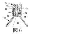
図5および図6は、中空の本体部分62およびそれと一体のネック部分64を有する熱可塑性容器60を示す。ネック部分64は外部ラグを有さず、代わりに、テーパ状雄コネクタ70のカラー72は、アクセス通路65内の円錐形の前室66およびテーパ状スロート領域68を規定するネック部分64の上にスライド可能に受け入れられる。内向きに延出する周囲フランジ74は、テーパ状雄コネクタ70のテーパ状チップ80を受け入れるための開口部76を規定する。テーパ状スロート領域68は、テーパ状雄コネクタ70のためのテーパ状雌コネクタとして機能する。 5 and 6 show a
完成した接続を図6に示す。カラー72は、ネック部分64のボス82によって係合され、内向きに延出するフランジ74は、チップ80の遠位端を封止して係合する。 The completed connection is shown in FIG. The
図7〜図10は本発明の別の実施形態を示し、図3〜図6に示すように鈍角を形成する代わりに、内側に延出するフランジが、容器ネック部分の内壁に対して約90度の角度でアクセス通路内に延出する。 7 to 10 show another embodiment of the present invention, in which instead of forming an obtuse angle as shown in FIGS. 3 to 6, an inwardly extending flange is about 90 relative to the inner wall of the container neck portion. Extend into the access passage at a right angle.
図7を参照すると、熱可塑性容器90は、中空の本体部分92と、アクセス通路96を規定する一体型のネック部分94とを有する。ネック部分94はまた、中空の本体部分92に隣接するテーパ状スロート領域98を規定し、内向きに延出する周囲フランジ102で終端し、周囲フランジ102は、ネック部分94の内壁に対して約90度の角度でアクセス通路96内に延出する。フランジ102は、テーパ状雄コネクタのテーパ状チップを受け入れるサイズの開口部またはアパーチャ106を規定する。ネック部分94はまた、テーパ状スロート領域98とフランジ102との間に円錐形の前室100を規定する。ボス104は、中空の本体部分92と一体型のネック部分94との接合部に位置する。 Referring to FIG. 7, the
内ねじ付きカラー112を備えたテーパ状雄コネクタ110は、図7で、フランジ102によって規定される開口部またはアパーチャ106に示されている。テーパ状雄コネクタがネック部分94にねじ込まれると、フランジ102は、チップ114がテーパ状スロート領域98に係合するまでチップ114に沿ってスライドし、それにより容器を封止する。フランジ102は、チップ114の遠位端部分に対して圧縮され、図8に示すように、容器に二次的封止を提供する。 The tapered
容器の構造の熱可塑性材料がテーパ状雄コネクタの構造の材料よりも比較的柔らかい場合、容器のネック部分の前室は追加の柔軟性を提供し、これによりネック部分に外部ラグを必要とせずにネック部分へのテーパ状雄コネクタのねじ込みを容易にする。 If the thermoplastic material of the vessel structure is relatively softer than the material of the tapered male connector structure, the anterior chamber of the neck part of the container provides additional flexibility, which eliminates the need for external lugs on the neck part. Makes it easy to screw the tapered male connector into the neck.
図9および図10は、内ねじのないカラー122を有するテーパ状雄コネクタ120を備えた容器90を示す。テーパ状雄コネクタのチップ124は、フランジ102によって規定される開口部106を通過し、カラー120がボス104と係合する一方で、テーパ状スロート領域98内にスライド可能に受け入れられる。同時に、フランジ102は、チップ124の遠位端部分に付勢され、容器に二次的封止を提供する。 9 and 10 show a
図1〜図6に示す実施形態では、封止フランジは、鈍角で、好ましくは約120度〜約150度の範囲の角度で内向きに延出する。図1〜図4には台形断面を有するフランジが示され、図5および図6には四辺形断面を有するフランジが示されている。 In the embodiments shown in FIGS. 1 to 6, the sealing flange extends inward at an obtuse angle, preferably at an angle in the range of about 120 degrees to about 150 degrees. FIGS. 1 to 4 show a flange having a trapezoidal cross section, and FIGS. 5 and 6 show a flange having a quadrilateral cross section.
熱可塑性の気密封止容器の形成、充填、および封止の手順は、当技術分野でよく知られており、一般に、Weilerらの米国特許第3,597,793号に記載されている。本発明を具現化する容器は、Weilerらの米国特許第4,178,976号に記載されているように、当技術分野で既知の技術を使用して、滅菌または無菌条件下で形成、充填、および封止することができる。適切な熱可塑性ポリオレフィン構成材料は、ポリプロピレン(PP)、高密度ポリエチレン(HDPE)、低密度ポリエチレン(LDPE)などである。特に好ましい構成材料はポリプロピレンである。 Procedures for forming, filling, and sealing thermoplastic airtight sealed containers are well known in the art and are generally described in US Pat. No. 3,597,793 by Weiler et al. Containers embodying the present invention are formed and filled under sterile or aseptic conditions using techniques known in the art, as described in Weiler et al., US Pat. No. 4,178,976. , And can be sealed. Suitable thermoplastic polyolefin constituent materials are polypropylene (PP), high density polyethylene (HDPE), low density polyethylene (LDPE) and the like. A particularly preferred constituent material is polypropylene.
前述の説明および図面は、本発明の例示であり、限定するものとして解釈されるべきではない。本発明の精神および範囲内のさらなる他の変形が可能であり、当業者には容易に提示されるであろう。 The above description and drawings are exemplary of the invention and should not be construed as limiting. Further modifications within the spirit and scope of the present invention are possible and will be readily presented to those of skill in the art.
Claims (14)
Translated fromJapanese前記ネック部分が、前記中空の本体部分へのアクセス通路を規定し、前記アクセス通路が、前室と、テーパ状雄コネクタを受け入れるサイズのテーパ状雌コネクタとして構成されたスロート領域とを含み、
一対の対向するラグが、前記封止フランジの下の前記ネック部分にある、
熱可塑性材料の気密封止容器。A hollow body part, a neck part that is integrated with the body part and terminates with a sealing flange that extends inward around it, and a removable cap that defines an opening sized to accommodate the tapered male connector. Includes a removable cap that is integrated with the removable cap and is coupled to the sealing flange by a fragile web that is integral with the sealing flange.
The neck portion defines an access passage to the hollow body portion, the access passage includes an anterior chamber and a throat region configured as a tapered female connector sized to accommodate a tapered male connector.
A pair of opposing lugs are located on the neck portion below the sealing flange.
Airtight sealed container made of thermoplastic material.
Applications Claiming Priority (2)
| Application Number | Priority Date | Filing Date | Title |
|---|---|---|---|
| US16/525,146US10793323B2 (en) | 2015-01-14 | 2019-07-29 | Container with tapered connector |
| US16/525,146 | 2019-07-29 |
Publications (1)
| Publication Number | Publication Date |
|---|---|
| JP2021020739Atrue JP2021020739A (en) | 2021-02-18 |
Family
ID=74574055
Family Applications (1)
| Application Number | Title | Priority Date | Filing Date |
|---|---|---|---|
| JP2020128110APendingJP2021020739A (en) | 2019-07-29 | 2020-07-29 | Hermetically sealed thermoplastic container |
Country Status (1)
| Country | Link |
|---|---|
| JP (1) | JP2021020739A (en) |
Citations (14)
| Publication number | Priority date | Publication date | Assignee | Title |
|---|---|---|---|---|
| JPS58146348A (en)* | 1982-02-08 | 1983-08-31 | アストラ・レ−ケメデル・アクチエボラ−グ | Unit dosing type syringe container |
| JPS58501542A (en)* | 1981-09-28 | 1983-09-16 | パラディス、ジョセフ・ア−ル | Connecting cap container method and structure |
| US4995519A (en)* | 1988-01-26 | 1991-02-26 | Howard Rose | Ampoules |
| JPH05500020A (en)* | 1989-12-11 | 1993-01-14 | アストラ・アクチエボラーグ | unit dose container |
| JPH06218025A (en)* | 1992-09-12 | 1994-08-09 | Bernd Hansen | Ampul |
| JPH11347101A (en)* | 1998-05-26 | 1999-12-21 | Automatic Liquid Packaging Inc | Hermetically sealed container including nozzle with sealing bead |
| JP2003116964A (en)* | 2001-10-16 | 2003-04-22 | Nippon Tenganyaku Kenkyusho:Kk | ampoule |
| JP2005516862A (en)* | 2002-02-05 | 2005-06-09 | ウェイラー エンジニアリング インコーポレイテッド | Hermetically sealed container with integrated drop dispenser |
| US20090008354A1 (en)* | 2007-07-05 | 2009-01-08 | Weiler Gerhard H | Hermetically sealed container |
| JP2009286498A (en)* | 2009-09-09 | 2009-12-10 | Pharmapack Kk | Liquid medicine container |
| JP2012034939A (en)* | 2010-08-10 | 2012-02-23 | Pharmapack Kk | Liquid medicine container |
| US20160200484A1 (en)* | 2015-01-14 | 2016-07-14 | Weiler Engineering, Inc. | Ampoule with dual luer fitting |
| US20160220444A1 (en)* | 2013-09-12 | 2016-08-04 | Fresenius Kabi Deutschland Gmbh | Ampoule for medical liquid and method for producing an ampoule |
| DE102017009012A1 (en)* | 2017-09-26 | 2019-03-28 | Kocher-Plastik Maschinenbau Gmbh | Container and connecting and manufacturing device |
- 2020
- 2020-07-29JPJP2020128110Apatent/JP2021020739A/enactivePending
Patent Citations (14)
| Publication number | Priority date | Publication date | Assignee | Title |
|---|---|---|---|---|
| JPS58501542A (en)* | 1981-09-28 | 1983-09-16 | パラディス、ジョセフ・ア−ル | Connecting cap container method and structure |
| JPS58146348A (en)* | 1982-02-08 | 1983-08-31 | アストラ・レ−ケメデル・アクチエボラ−グ | Unit dosing type syringe container |
| US4995519A (en)* | 1988-01-26 | 1991-02-26 | Howard Rose | Ampoules |
| JPH05500020A (en)* | 1989-12-11 | 1993-01-14 | アストラ・アクチエボラーグ | unit dose container |
| JPH06218025A (en)* | 1992-09-12 | 1994-08-09 | Bernd Hansen | Ampul |
| JPH11347101A (en)* | 1998-05-26 | 1999-12-21 | Automatic Liquid Packaging Inc | Hermetically sealed container including nozzle with sealing bead |
| JP2003116964A (en)* | 2001-10-16 | 2003-04-22 | Nippon Tenganyaku Kenkyusho:Kk | ampoule |
| JP2005516862A (en)* | 2002-02-05 | 2005-06-09 | ウェイラー エンジニアリング インコーポレイテッド | Hermetically sealed container with integrated drop dispenser |
| US20090008354A1 (en)* | 2007-07-05 | 2009-01-08 | Weiler Gerhard H | Hermetically sealed container |
| JP2009286498A (en)* | 2009-09-09 | 2009-12-10 | Pharmapack Kk | Liquid medicine container |
| JP2012034939A (en)* | 2010-08-10 | 2012-02-23 | Pharmapack Kk | Liquid medicine container |
| US20160220444A1 (en)* | 2013-09-12 | 2016-08-04 | Fresenius Kabi Deutschland Gmbh | Ampoule for medical liquid and method for producing an ampoule |
| US20160200484A1 (en)* | 2015-01-14 | 2016-07-14 | Weiler Engineering, Inc. | Ampoule with dual luer fitting |
| DE102017009012A1 (en)* | 2017-09-26 | 2019-03-28 | Kocher-Plastik Maschinenbau Gmbh | Container and connecting and manufacturing device |
Similar Documents
| Publication | Publication Date | Title |
|---|---|---|
| US10363369B2 (en) | Ampoule with dual Luer fitting | |
| US10793323B2 (en) | Container with tapered connector | |
| US20220226630A1 (en) | Flexible Cap for Conical Connectors | |
| AU2004229139B2 (en) | Ampoule | |
| US8915902B2 (en) | Inter vial transfer system | |
| JP2024109938A (en) | Container and method of joining and forming | |
| CN113208916B (en) | Vial adapter device | |
| JP3219248U (en) | Needleless syringe connector lid and container | |
| US5064059A (en) | Dual container system with extractor for stopper | |
| JP2017522235A5 (en) | ||
| CZ217095A3 (en) | Plug made of elastomeric material | |
| JP2018052537A (en) | Female connector | |
| EP0591156B1 (en) | Unit dose container | |
| JP6564017B2 (en) | Container with headpiece capable of or filled with medium | |
| JP2021020739A (en) | Hermetically sealed thermoplastic container | |
| HK1001552B (en) | Unit dose container | |
| WO2018173925A1 (en) | Female syringe and syringe kit | |
| US11464909B2 (en) | Syringe tip cap | |
| US20240042189A1 (en) | Container With Threaded Connector | |
| US20250281357A1 (en) | Container with threaded connector | |
| US20230301870A1 (en) | Container With Threaded Connector | |
| US11382832B2 (en) | Dip tube | |
| US10173810B2 (en) | Caps and adapters for containers | |
| JP2001502938A (en) | Syringe system containing two separate prefilled barrels | |
| KR101350305B1 (en) | Medicine container with double chamber and disposable syringe including the container |
Legal Events
| Date | Code | Title | Description |
|---|---|---|---|
| A621 | Written request for application examination | Free format text:JAPANESE INTERMEDIATE CODE: A621 Effective date:20201019 | |
| A977 | Report on retrieval | Free format text:JAPANESE INTERMEDIATE CODE: A971007 Effective date:20210916 | |
| A131 | Notification of reasons for refusal | Free format text:JAPANESE INTERMEDIATE CODE: A131 Effective date:20210928 | |
| A521 | Request for written amendment filed | Free format text:JAPANESE INTERMEDIATE CODE: A523 Effective date:20211224 | |
| A131 | Notification of reasons for refusal | Free format text:JAPANESE INTERMEDIATE CODE: A131 Effective date:20220510 | |
| A131 | Notification of reasons for refusal | Free format text:JAPANESE INTERMEDIATE CODE: A131 Effective date:20221122 | |
| A02 | Decision of refusal | Free format text:JAPANESE INTERMEDIATE CODE: A02 Effective date:20230620 |