JP2021020192A - Vibration generation device - Google Patents
Vibration generation deviceDownload PDFInfo
- Publication number
- JP2021020192A JP2021020192AJP2019140054AJP2019140054AJP2021020192AJP 2021020192 AJP2021020192 AJP 2021020192AJP 2019140054 AJP2019140054 AJP 2019140054AJP 2019140054 AJP2019140054 AJP 2019140054AJP 2021020192 AJP2021020192 AJP 2021020192A
- Authority
- JP
- Japan
- Prior art keywords
- vibration generator
- vibration
- drive control
- control unit
- pulse
- Prior art date
- Legal status (The legal status is an assumption and is not a legal conclusion. Google has not performed a legal analysis and makes no representation as to the accuracy of the status listed.)
- Pending
Links
Images


Landscapes
- Apparatuses For Generation Of Mechanical Vibrations (AREA)
- Reciprocating, Oscillating Or Vibrating Motors (AREA)
Abstract
Translated fromJapaneseDescription
Translated fromJapanese本発明は、振動発生装置に関する。 The present invention relates to a vibration generator.
従来より、触覚モジュール、音声モジュール及び視覚モジュールのうちの少なくとも1つを含むプライミング及びアラートシステムと、前記プライミング及びアラートシステムに動作可能に接続された入力/出力装置と、前記プライミング及びアラートシステムに動作可能に接続されて、該プライミング及びアラートシステムに、アラートを生成する前にプライミングキューを出力させるように適合された処理装置と、を備えることを特徴とする電子装置がある。アラートは、例えば振動による触感として与えられる(例えば、特許文献1参照)。 Conventionally, a priming and alert system including at least one of a tactile module, a voice module, and a visual module, an input / output device operably connected to the priming and alert system, and an operation on the priming and alert system. There are electronic devices that are capable of being connected and that the priming and alerting system comprises a processing device adapted to output a priming queue before generating an alert. The alert is given, for example, as a tactile sensation due to vibration (see, for example, Patent Document 1).
ところで、従来の電子装置では、アラートを付与するための振動は、一定周期で一定振幅の振動を繰り返すものであるため、電子装置がアラート以外の機能のために付与する振動と区別し難い。 By the way, in a conventional electronic device, the vibration for giving an alert repeats a vibration having a constant amplitude at a fixed cycle, so that it is difficult to distinguish it from a vibration given by the electronic device for a function other than the alert.
区別し易くする方法としては、周波数を変えたり間欠駆動させたりする方法があるが、振動エネルギーを大きく低下させてしまうことになり、アラートとして好ましくないという問題があった。 As a method of making it easy to distinguish, there is a method of changing the frequency or intermittently driving, but there is a problem that the vibration energy is greatly reduced, which is not preferable as an alert.
そこで、他の振動と区別しやすく、かつ振動エネルギーの低下を抑えられる振動を付与可能な振動発生装置を提供することを目的とする。 Therefore, it is an object of the present invention to provide a vibration generator capable of imparting vibration that can be easily distinguished from other vibrations and that can suppress a decrease in vibration energy.
本発明の実施の形態の振動発生装置は、固定体と、前記固定体に対して振動可能に支持された可動体とを有する振動発生器と、前記可動体に加振力を付与する駆動制御を行う駆動制御部とを含み、前記駆動制御部は、一定の周期で複数回にわたる加振力の付与を位相をずらして継続的に行うことを特徴とする。 The vibration generator according to the embodiment of the present invention includes a vibration generator having a fixed body and a movable body vibrably supported by the fixed body, and a drive control for applying a vibrating force to the movable body. The drive control unit includes a drive control unit that performs the above-mentioned operation, and the drive control unit is characterized in that the vibration force is continuously applied a plurality of times in a fixed cycle with a phase shift.
他の振動と区別しやすく、かつ振動エネルギーの低下を抑えられる振動を付与可能な振動発生装置を提供することができる。 It is possible to provide a vibration generator capable of imparting vibration that is easily distinguishable from other vibrations and that can suppress a decrease in vibration energy.
以下、本発明の振動発生装置を適用した実施の形態について説明する。 Hereinafter, embodiments to which the vibration generator of the present invention is applied will be described.
<実施の形態>
図1は、実施の形態の振動発生装置100を示す図である。振動発生装置100は、振動発生器110と駆動制御装置120を含む。振動発生器110は、駆動制御装置120を介してPC(Personal Computer)10に接続されている。<Embodiment>
FIG. 1 is a diagram showing a
振動発生器110は、ケース111、振動素子112、及びケーブル113を有し、ケーブル113を介して駆動制御装置120に接続されている。ケース111は、利用者が手等で触れる筐体である。振動素子112は、ケース111に内蔵されており、コイル112A(固定体の一例)と磁石112B(可動体の一例)を有する。振動素子112は、一例として、ボイスコイルモータのようなタイプの振動素子である。 The
磁石112Bは、コイル112Aに対して振動可能に支持されている。また、磁石112Bは、コイル112Aに対して弾性的に支持されている。弾性的に支持されるとは、磁石112Bがコイル112Aに対して振動できないように堅牢な状態で固定されているのではなく、ある程度の弾性を有して振動可能に支持されることをいう。 The
ここでは一例として、ケース111に固定されたコイル112Aに駆動信号の電流が流れると磁石112Bが振動する形態について説明するが、ケース111に磁石112Bが固定されていてコイル112Aが振動する形態であってもよい。 Here, as an example, a mode in which the
振動素子112は、駆動制御装置120及びケーブル113を介してPC10から入力される駆動信号によって駆動され、振動する。また、駆動信号の周波数は振動素子112の固有振動を与える周波数に設定されている。 The vibrating
駆動制御装置120は、ケーブル120Aを介してPC10のUSB(Universal Serial Bus)端子に接続されており、駆動制御部121を有する。駆動制御部121は、振動素子112の駆動制御を行うドライバ回路であり、PC10からケーブル120Aを介して入力される駆動信号を増幅等して振動発生器110に出力し、駆動信号に応じて振動素子112の磁石112Bを加振する。駆動制御部121は、駆動信号の信号レベル(電圧値)を電流値に変換して振動素子112のコイル112Aに入力する。 The
なお、駆動信号を表すデータは、PC10のメモリに格納されており、PC10が所定のアプリケーションプログラム等を実行することによって、駆動制御装置120に出力される。 The data representing the drive signal is stored in the memory of the PC 10, and is output to the
図2は、駆動信号を示す図である。横軸は時間軸であり、縦軸は駆動信号の信号レベル(電圧値)を示す。 FIG. 2 is a diagram showing a drive signal. The horizontal axis is the time axis, and the vertical axis is the signal level (voltage value) of the drive signal.
駆動信号は、一例として、周波数がf[Hz]でデューティ比が50%のパルスをN個有するパルス群をM個含み、パルス群同士の間に遅延時間tdを設けた信号である。f[Hz]は、一例として、100Hzから数100Hzであり、1kHz以下である。 As an example, the drive signal is a signal in which M pulse groups having N pulses having a frequency of f [Hz] and a duty ratio of 50% are provided, and a delay time td is provided between the pulse groups. As an example, f [Hz] is from 100 Hz to several hundred Hz, and is 1 kHz or less.
ここで、パルスとは、パルス群に一例として5個含まれるパルスの各々をいう。各パルスは、周期Tの前半で矩形状に変化するパルスであるが、周期Tの後半で矩形状に変化するパルスであってもよい。なお、ここでは矩形波状のパルスを示すが、図5に示すような正弦波状であってもよい。 Here, the pulse means each of five pulses included in the pulse group as an example. Each pulse is a pulse that changes in a rectangular shape in the first half of the period T, but may be a pulse that changes in a rectangular shape in the latter half of the period T. Although the rectangular wavy pulse is shown here, it may be a sinusoidal pulse as shown in FIG.
また、パルス群とは、図2に示すように、区間Pに含まれる一定周期かつ一定振幅の複数のパルスをいう。各パルス群は、一定周期かつ一定振幅の複数のパルスを含むため、各パルス群は、振動素子112に一定の周期で複数回にわたる加振力の付与を行うことになる。 Further, as shown in FIG. 2, the pulse group refers to a plurality of pulses having a constant period and a constant amplitude included in the section P. Since each pulse group includes a plurality of pulses having a constant cycle and a constant amplitude, each pulse group applies a vibrating force to the vibrating element 112 a plurality of times at a constant cycle.
ここでは一例として、Nが5でMが5の形態について説明するが、Nは2以上の整数であればよく、Mは3以上の整数であればよい。 Here, as an example, the form in which N is 5 and M is 5, but N may be an integer of 2 or more, and M may be an integer of 3 or more.
また、Mは3以上であることから、駆動信号は複数のパルス群を含むことになり、遅延時間tdを挟んでパルス群による複数のパルスで振動素子112を継続的に駆動することになる。継続的に駆動するとは、繰り返し駆動することをいう。Mが5の場合は、5個のパルス群で振動素子112を継続的に加振力を付与する(駆動する)ことになる。 Further, since M is 3 or more, the drive signal includes a plurality of pulse groups, and the vibrating
遅延時間tdは、パルスの周期Tとは異なる長さを有する。遅延時間tdは、1つのパルス群に含まれる最後のパルスの周期Tが終了した後に、次のパルス群の最初のパルスの周期Tが開始するまでの時間であり、待機時間として捉えることもできる時間(期間)である。 The delay time td has a length different from the pulse period T. The delay time td is the time from the end of the cycle T of the last pulse included in one pulse group to the start of the cycle T of the first pulse of the next pulse group, and can be regarded as a standby time. Time (duration).
このようなパルスの周期Tとは異なる長さを有する遅延時間tdをパルス群同士の間に設けると、パルス群同士の間の位相をずらすことになり、1つのパルス群による振動素子112の駆動と、次のパルス群による振動素子112の駆動との間において、パルス群に含まれる連続した5個のパルスによる振動素子112の駆動とは異なるリズムになる。 If a delay time td having a length different from the pulse period T is provided between the pulse groups, the phases between the pulse groups are shifted, and the
このように、パルス群同士の間でリズムを変えるのは、一定周期かつ一定振幅のような振動と区別しやすい振動を付与可能にするためである。この詳細については後述する。 In this way, the reason why the rhythm is changed between the pulse groups is to make it possible to apply a vibration that is easily distinguishable from a vibration such as a constant period and a constant amplitude. The details will be described later.
ここで、遅延時間tdの最適値はT/2であり、パルスの位相で180度である。ここでは遅延時間tdをT/2に設定するため、5個のパルス群の位相を反転させながら振動素子112に加振力の付与を継続的に行うことになる。 Here, the optimum value of the delay time td is T / 2, and the phase of the pulse is 180 degrees. Here, since the delay time td is set to T / 2, the exciting force is continuously applied to the vibrating
遅延時間tdは、周期Tと異なればよいため、原理的にはパルスの位相で0度より大きく、360度と等しくない時間であればよいが、90度から270度の範囲に相当する時間、又は、この時間に周期Tの整数倍に相当する時間を加えて時間であることが好ましい。 Since the delay time td may be different from the period T, in principle, the pulse phase may be larger than 0 degrees and not equal to 360 degrees, but the time corresponding to the range of 90 degrees to 270 degrees, Alternatively, it is preferable that the time is obtained by adding a time corresponding to an integral multiple of the period T to this time.
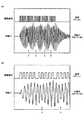
図3は、駆動信号と加振力を示す図である。図3(A)、(B)において、横軸は時間軸であり、縦軸は駆動信号及び加振力の振幅を表す。 FIG. 3 is a diagram showing a drive signal and an exciting force. In FIGS. 3A and 3B, the horizontal axis represents the time axis, and the vertical axis represents the amplitude of the drive signal and the exciting force.
加振力は、コイル112Aが発生する電磁力が磁石112Bを加振する力である。図3(A)には、駆動信号と加振力の波形の全体を示し、図3(B)には時間軸方向に拡大した波形を示す。 The exciting force is a force that the electromagnetic force generated by the coil 112A vibrates the
駆動信号による電流をコイル112Aに流して磁石112Bを加振すると、時間軸方向における加振力の分布は、パルス群に合わせて5個の群になり、5個の群同士の間の4箇所では、各群の中に比べて振幅が減衰している(矢印Xで示す4箇所参照)。 When the current from the drive signal is passed through the coil 112A to vibrate the
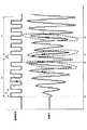
図4は、駆動信号と加振力をさらに拡大して示す図である。図4には時間軸tを示す。 FIG. 4 is a diagram showing the drive signal and the exciting force in a further enlarged manner. FIG. 4 shows the time axis t.
時刻t0で1個目のパルス群の最初のパルスが立上ると、磁石112Bの加振が開始し、時間の経過とともに加振力は増大する。時刻t1で1個目のパルス群の5個目のパルスが立下がる直前には、破線の楕円と矢印で示すように、加振力は最大になる。 When the first pulse of the first pulse group rises at time t0, the vibration of the
そして、時刻t1の後の遅延時間tdが経過する頃に加振力が下向きになっているときに、時刻t2で2個目のパルス群の最初のパルスが立ち上がる。そして、時刻t2の後の時刻t3において2個目のパルス群によって加振力の振幅は再び増大する。 Then, when the exciting force is downward when the delay time td after the time t1 elapses, the first pulse of the second pulse group rises at the time t2. Then, at time t3 after time t2, the amplitude of the exciting force is increased again by the second pulse group.
このように、加振力が下向きになっているときに逆向きの加振力を付与するように時刻t2で2個目のパルス群の最初のパルスが立ち上がると、下向きの加振力によって加振される磁石112Bは、下向きの加振力の振動の途中で逆方向に加振されることになる。 In this way, when the first pulse of the second pulse group rises at time t2 so as to apply the excitation force in the opposite direction when the excitation force is downward, the excitation force is applied downward. The
このように、遅延時間tdによって位相をずらしたパルス群で継続的に磁石112Bを加振すると、パルス群同士の間でリズムが不連続に変化し、振動発生器110に触れる利用者の手等に小突かれたような触感を提供することができる。 In this way, when the
このような小突かれたような触感は、5個のパルス群を含む駆動信号で振動素子112を駆動する場合には、4回得られることになる。小突かれたような触感は、パルス群の中の一定周期かつ一定振幅の5つのパルスによって提供される略一定の触感とは異なり、瞬間的にリズムが不連続に変化することによってコツッと手先に残る触感である。 Such a tactile sensation of being struck is obtained four times when the vibrating
このように、2個目以降のパルス群で、1個前のパルス群による加振力に対して振動の途中で逆方向に加振するようにすれば、加振力のリズムを不連続に変化させることができる。遅延時間tdは、振動発生器110の各部のヤング率等を考慮して、逆向きに加振できるように最適な時間に設定すればよい。 In this way, if the second and subsequent pulse groups are vibrated in the opposite direction in the middle of vibration with respect to the exciting force of the previous pulse group, the rhythm of the exciting force becomes discontinuous. Can be changed. The delay time td may be set to an optimum time so that vibration can be performed in the opposite direction in consideration of Young's modulus of each part of the
以上のように、実施の形態によれば、パルス群同士の位相をずらした駆動信号で振動素子112を駆動することにより、パルス群が切り替わるタイミングで(厳密には少し遅れて)不連続に変化する小突かれたような触感を提供することができる。 As described above, according to the embodiment, by driving the vibrating
したがって、他の振動と区別しやすく、かつ振動エネルギーの低下を抑えられる振動を付与可能な振動発生装置100を提供することができる。 Therefore, it is possible to provide the
このように他の振動と区別しやすい振動を付与可能であれば、重要度の高いアラートとして用いる場合に非常に適しており、アラート以外にも利用可能である。 If it is possible to give a vibration that is easily distinguishable from other vibrations in this way, it is very suitable for use as an alert of high importance, and it can be used for other than alerts.
なお、以上では、振動発生装置100が手で握るタイプである形態について説明したが、振動発生装置100は、スマートフォン、タブレットコンピュータ、又は、車両の室内又は車体の外部に配置される操作部等に設けられていてもよい。 In the above, the form in which the
また、以上では、遅延時間tdは、好適には、90度から270度の範囲に相当する時間、又は、この時間に周期Tの整数倍に相当する時間を加えて時間であることが好ましい形態について説明した。90度から270度の範囲に相当する時間に周期Tの整数倍に相当する時間を加えて時間は、図4における時刻t2のように、1個前のパルス群による加振力がある程度残っている間に次のパルス群による駆動を開始することが望ましいため、整数倍とは2倍から5倍程度である。 Further, in the above, the delay time td is preferably a time corresponding to a range of 90 degrees to 270 degrees, or a time obtained by adding a time corresponding to an integral multiple of the period T to this time. Was explained. By adding the time corresponding to an integral multiple of the period T to the time corresponding to the range of 90 degrees to 270 degrees, the vibration force due to the previous pulse group remains to some extent as shown at time t2 in FIG. Since it is desirable to start driving by the next pulse group while the pulse group is in progress, the integer multiple is about 2 to 5 times.
また、以上では、駆動信号のデューティ比が50%である形態について説明したが、ある程度の加振力を振動素子112が発生できるのであれば、50%には限られない。また、パルス群に含まれる複数のパルスのデューティ比は等しくなくてもよい。例えば時間の経過に伴って連続的に増大又は減少させてもよい。 Further, although the mode in which the duty ratio of the drive signal is 50% has been described above, the duty ratio is not limited to 50% as long as the vibrating
また、以上では遅延時間tdが正の値をとる形態について説明したが、遅延時間tdは、負の値をとってもよい。例えば、図6に示すように、パルス群に含まれる最後のパルスの周期Tが終了する前に次のパルス群の最初のパルスが立ち上がるようにしてもよい。この場合に、パルス群に含まれる最後のパルスが立ち下がってから、次のパルス群の最初のパルスが立ち上がるようにすればよい。 Further, although the mode in which the delay time td takes a positive value has been described above, the delay time td may take a negative value. For example, as shown in FIG. 6, the first pulse of the next pulse group may rise before the period T of the last pulse included in the pulse group ends. In this case, the first pulse of the next pulse group may rise after the last pulse included in the pulse group falls.
また、以上では、振動素子112がコイル112Aと磁石112Bを含む形態について説明したが、振動素子112は、このような形態に限られるものではなく、振動を発生可能な素子であればよい。 Further, although the form in which the vibrating
以上、本発明の例示的な実施の形態の振動発生装置について説明したが、本発明は、具体的に開示された実施の形態に限定されるものではなく、特許請求の範囲から逸脱することなく、種々の変形や変更が可能である。 Although the vibration generator according to the exemplary embodiment of the present invention has been described above, the present invention is not limited to the specifically disclosed embodiments and does not deviate from the scope of claims. , Various modifications and changes are possible.
100 振動発生装置
110 振動発生器
112 振動素子
112A コイル
112B 磁石
120 駆動制御装置
121 駆動制御部100
Claims (7)
Translated fromJapanese前記可動体に加振力を付与する駆動制御を行う駆動制御部と
を含み、
前記駆動制御部は、一定の周期で複数回にわたる加振力の付与を位相をずらして継続的に行うことを特徴とする振動発生装置。A vibration generator having a fixed body and a movable body oscillatingly supported by the fixed body,
Including a drive control unit that performs drive control that applies a vibrating force to the movable body.
The drive control unit is a vibration generator characterized in that the excitation force is continuously applied a plurality of times in a fixed cycle by shifting the phase.
前記駆動制御部が前記一定の周期で複数回にわたる加振力の付与を行う周波数は、前記可動体の固有振動を与える周波数である、請求項1乃至4のいずれか一項記載の振動発生装置。The movable body is elastically supported by the fixed body and is supported by the fixed body.
The vibration generator according to any one of claims 1 to 4, wherein the frequency at which the drive control unit applies the exciting force a plurality of times in the fixed cycle is a frequency at which the natural vibration of the movable body is applied. ..
Priority Applications (1)
| Application Number | Priority Date | Filing Date | Title |
|---|---|---|---|
| JP2019140054AJP2021020192A (en) | 2019-07-30 | 2019-07-30 | Vibration generation device |
Applications Claiming Priority (1)
| Application Number | Priority Date | Filing Date | Title |
|---|---|---|---|
| JP2019140054AJP2021020192A (en) | 2019-07-30 | 2019-07-30 | Vibration generation device |
Publications (1)
| Publication Number | Publication Date |
|---|---|
| JP2021020192Atrue JP2021020192A (en) | 2021-02-18 |
Family
ID=74573517
Family Applications (1)
| Application Number | Title | Priority Date | Filing Date |
|---|---|---|---|
| JP2019140054APendingJP2021020192A (en) | 2019-07-30 | 2019-07-30 | Vibration generation device |
Country Status (1)
| Country | Link |
|---|---|
| JP (1) | JP2021020192A (en) |
Citations (3)
| Publication number | Priority date | Publication date | Assignee | Title |
|---|---|---|---|---|
| JP2004186831A (en)* | 2002-11-29 | 2004-07-02 | Alps Electric Co Ltd | Vibration generator |
| JP2007075751A (en)* | 2005-09-15 | 2007-03-29 | Sony Corp | Tactile sensation offering mechanism and electronic equipment equipped with tactile sensation offering mechanism |
| JP6383048B1 (en)* | 2017-05-18 | 2018-08-29 | レノボ・シンガポール・プライベート・リミテッド | Tactile feedback system, electronic device, and method for adjusting vibration intensity |
- 2019
- 2019-07-30JPJP2019140054Apatent/JP2021020192A/enactivePending
Patent Citations (3)
| Publication number | Priority date | Publication date | Assignee | Title |
|---|---|---|---|---|
| JP2004186831A (en)* | 2002-11-29 | 2004-07-02 | Alps Electric Co Ltd | Vibration generator |
| JP2007075751A (en)* | 2005-09-15 | 2007-03-29 | Sony Corp | Tactile sensation offering mechanism and electronic equipment equipped with tactile sensation offering mechanism |
| JP6383048B1 (en)* | 2017-05-18 | 2018-08-29 | レノボ・シンガポール・プライベート・リミテッド | Tactile feedback system, electronic device, and method for adjusting vibration intensity |
Similar Documents
| Publication | Publication Date | Title |
|---|---|---|
| US8098234B2 (en) | Haptic feedback system with stored effects | |
| CN105389000B (en) | Haptic notifications | |
| US8179202B2 (en) | Multiple pulse width modulation | |
| CN103970270B (en) | Overdrive actuator voltage to generate haptic effects | |
| EP1923774B1 (en) | Method, apparatus, and computer program product providing vibration control interface | |
| WO2019211591A1 (en) | Methods and apparatus for outputting a haptic signal to a haptic transducer | |
| CN108183654A (en) | The calibration method and device of linear vibrator resonant frequency | |
| JP2020025453A (en) | Motor driving method, terminal device, and computer-readable recording medium | |
| WO2010047547A3 (en) | Vibration motor driving apparatus using a serial interface | |
| CN108288937A (en) | The driving method and its driving circuit structure of linear resonance device | |
| JP2021020192A (en) | Vibration generation device | |
| CN1171185C (en) | Vibrator and method for controlling the vibrator | |
| JP2007085867A (en) | Method and apparatus for driving ultrasonic transmitter | |
| JP2011254610A (en) | Driving device for ultrasonic motor | |
| CN116266075A (en) | Vibration generating device and vibration generating method | |
| CN110380665A (en) | A kind of generation method, electronic equipment and storage medium controlling signal | |
| CN114690902A (en) | Tactile stimulation apparatus, driving method, wearable device, and storage medium | |
| KR101398496B1 (en) | Vibrotactile traveling wave generation method for occurring funneling effect efficiently using vibretactile difference thresholds | |
| CN115497442A (en) | Control method and device for sounding of buzzer and buzzer | |
| JP2782306B2 (en) | Ultrasonic motor driving method | |
| JP6269959B2 (en) | Sound generator | |
| US20240367037A1 (en) | Haptic-enabled gaming controllers | |
| JP2023132566A (en) | Control method of actuator, haptic output device, and electronic apparatus | |
| JP2008233582A (en) | Sound generating circuit and method, and buzzer sound generating method | |
| CN120306231A (en) | A driving method, device, electronic device and storage medium of a vibration exciter |
Legal Events
| Date | Code | Title | Description |
|---|---|---|---|
| A621 | Written request for application examination | Free format text:JAPANESE INTERMEDIATE CODE: A621 Effective date:20220518 | |
| A977 | Report on retrieval | Free format text:JAPANESE INTERMEDIATE CODE: A971007 Effective date:20230310 | |
| A131 | Notification of reasons for refusal | Free format text:JAPANESE INTERMEDIATE CODE: A131 Effective date:20230328 | |
| A521 | Request for written amendment filed | Free format text:JAPANESE INTERMEDIATE CODE: A523 Effective date:20230524 | |
| A131 | Notification of reasons for refusal | Free format text:JAPANESE INTERMEDIATE CODE: A131 Effective date:20230905 | |
| A601 | Written request for extension of time | Free format text:JAPANESE INTERMEDIATE CODE: A601 Effective date:20231030 | |
| A521 | Request for written amendment filed | Free format text:JAPANESE INTERMEDIATE CODE: A523 Effective date:20231218 | |
| A02 | Decision of refusal | Free format text:JAPANESE INTERMEDIATE CODE: A02 Effective date:20240305 |