Movatterモバイル変換


[0]ホーム

URL:


JP2021018370A - Optical connector and transmission apparatus - Google Patents

Optical connector and transmission apparatus
Download PDF

Info

Publication number
JP2021018370A
JP2021018370AJP2019135238AJP2019135238AJP2021018370AJP 2021018370 AJP2021018370 AJP 2021018370AJP 2019135238 AJP2019135238 AJP 2019135238AJP 2019135238 AJP2019135238 AJP 2019135238AJP 2021018370 AJP2021018370 AJP 2021018370A
Authority
JP
Japan
Prior art keywords
optical fiber
optical connector
optical
cooling medium
communication
Prior art date
Legal status (The legal status is an assumption and is not a legal conclusion. Google has not performed a legal analysis and makes no representation as to the accuracy of the status listed.)
Granted
Application number
JP2019135238A
Other languages
Japanese (ja)
Other versions
JP7340376B2 (en
Inventor
剛久 奥田
Takehisa Okuda
剛久 奥田
赤羽 崇
Takashi Akahane
崇 赤羽
賢一 河西
Kenichi Kasai
賢一 河西
八若 正義
Masayoshi Hachiwaka
正義 八若
大泉 晴郎
Seiro Oizumi
晴郎 大泉
Current Assignee (The listed assignees may be inaccurate. Google has not performed a legal analysis and makes no representation or warranty as to the accuracy of the list.)
Mitsubishi Cable Industries Ltd
Mitsubishi Heavy Industries Ltd
Original Assignee
Mitsubishi Cable Industries Ltd
Mitsubishi Heavy Industries Ltd
Priority date (The priority date is an assumption and is not a legal conclusion. Google has not performed a legal analysis and makes no representation as to the accuracy of the date listed.)
Filing date
Publication date
Application filed by Mitsubishi Cable Industries Ltd, Mitsubishi Heavy Industries LtdfiledCriticalMitsubishi Cable Industries Ltd
Priority to JP2019135238ApriorityCriticalpatent/JP7340376B2/en
Publication of JP2021018370ApublicationCriticalpatent/JP2021018370A/en
Application grantedgrantedCritical
Publication of JP7340376B2publicationCriticalpatent/JP7340376B2/en
Activelegal-statusCriticalCurrent
Anticipated expirationlegal-statusCritical

Links

Images

Landscapes

Abstract

To provide an optical connector and a transmission apparatus that enable an optical fiber to be efficiently cooled.SOLUTION: An optical connector 10 comprises: a housing 21 accommodating an optical fiber 11; a fixing member 22 that fixes the optical fiber 11 with an outer periphery thereof surrounded in the housing 21; circulation parts 23 each that are provided on both sides of the fixing member 22 in an axial direction of the optical fiber 11 in the housing 21; a first supply/discharge part 24 and a second supply/discharge part 25 that supply a cooling medium to the one circulation part 23 of the two circulation parts 23 and discharge the cooling medium from the other circulation part 23; a first communication part 43 that is disposed at a portion, in the fixing member 22, facing the optical fiber 11 and communicates the two circulation parts 23; and a second communication part 45 that is provided at a portion, in the fixing member 22, different from the portion facing the optical fiber 11 and communicates the two circulation parts 23.SELECTED DRAWING: Figure 2

Description

Translated fromJapanese

本開示は、光コネクタ及び伝送装置に関する。 The present disclosure relates to optical connectors and transmission devices.

光ファイバを有する伝送装置によりレーザ光源のレーザ光をレーザ加工装置に伝送するとき、レーザ光源と光ファイバの一端部を光コネクタにより接続すると共に、光ファイバの他端部とレーザ加工装置を光コネクタにより接続する。このような伝送装置としては、例えば、下記特許文献に記載されたものがある。 When transmitting the laser light of a laser light source to a laser processing device by a transmission device having an optical fiber, one end of the laser light source and the optical fiber is connected by an optical connector, and the other end of the optical fiber and the laser processing device are connected by an optical connector. Connect with. As such a transmission device, for example, there is one described in the following patent documents.

特開2009−058547号公報JP-A-2009-058547

光ファイバは、一般的に、ガラス製のコアの外側にガラス製のクラッドが設けられ、このコアとクラッドからなる素線が樹脂製の被覆部により被覆されて構成されている。このような光ファイバは、外気温等の影響や光ファイバ自体の発熱により加熱されることを防ぐため、効率よく冷却することが求められる。 An optical fiber is generally configured by providing a glass clad on the outside of a glass core, and a wire composed of the core and the clad is covered with a resin coating portion. Such an optical fiber is required to be efficiently cooled in order to prevent it from being heated due to the influence of the outside air temperature or the heat generated by the optical fiber itself.

本開示では、光ファイバを効率よく冷却することが可能な光コネクタ及び伝送装置を提供することを目的とする。 An object of the present disclosure is to provide an optical connector and a transmission device capable of efficiently cooling an optical fiber.

本開示の第1態様に係る光コネクタは、光ファイバを収容するハウジングと、前記ハウジング内で前記光ファイバの外周を囲んだ状態で固定する固定部材と、前記ハウジング内において前記固定部材に対して前記光ファイバの軸方向の両側に設けられる流通部と、2つの前記流通部のうち一方の前記流通部に冷却媒体を供給する、または他方の前記流通部から前記冷却媒体を排出する給排部と、前記固定部材のうち前記光ファイバに面する部分に配置され、2つの前記流通部を連通する第1連通部と、前記固定部材のうち前記光ファイバに面する部分とは異なる部分に設けられ、2つの前記流通部を連通する第2連通部とを備える。 The optical connector according to the first aspect of the present disclosure includes a housing for accommodating an optical fiber, a fixing member for fixing the optical fiber in the housing while surrounding the outer periphery of the optical fiber, and the fixing member in the housing. A distribution unit provided on both sides in the axial direction of the optical fiber and a supply / discharge unit that supplies a cooling medium to one of the two distribution units or discharges the cooling medium from the other distribution unit. And the first communication portion which is arranged in the portion of the fixing member facing the optical fiber and communicates the two distribution portions, and the portion of the fixing member different from the portion facing the optical fiber. It is provided with a second communication section that communicates the two distribution sections.

本開示の第2態様に係る伝送装置は、光ファイバと、前記光ファイバの基端部及び先端部をそれぞれ支持し、内部にそれぞれ流通部を有する光コネクタと、前記光ファイバのうち2つの前記光コネクタから露出した部分を囲い、2つの前記光コネクタの前記流通部同士を接続する配管と、前記配管とは別個に2つの前記光コネクタの前記流通部同士を接続し、2つの前記光コネクタの前記流通部と前記配管とを含む流路を介して前記冷却媒体を循環させる循環装置と、を備え、2つの前記光コネクタのうち少なくとも前記光ファイバの前記先端部を支持する前記光コネクタは、上記の光コネクタが用いられる。 The transmission device according to the second aspect of the present disclosure includes an optical fiber, an optical connector that supports the base end portion and the tip end portion of the optical fiber, respectively, and has a distribution portion inside, and two of the optical fibers. A pipe that surrounds a portion exposed from the optical connector and connects the distribution parts of the two optical connectors, and a pipe that connects the distribution parts of the two optical connectors separately from the pipe, and two optical connectors. The optical connector comprising the circulation device for circulating the cooling medium through the flow path including the flow portion and the piping, and supporting at least the tip end portion of the optical fiber among the two optical connectors. , The above optical connector is used.

本開示によれば、光ファイバを効率よく冷却することが可能な光コネクタ及び伝送装置を提供することができる。 According to the present disclosure, it is possible to provide an optical connector and a transmission device capable of efficiently cooling an optical fiber.

図1は、本実施形態の伝送装置を表す概略構成図である。FIG. 1 is a schematic configuration diagram showing a transmission device of the present embodiment.図2は、本実施形態の光コネクタを表す断面図である。FIG. 2 is a cross-sectional view showing the optical connector of the present embodiment.図3は、図2のIII−III断面図である。FIG. 3 is a sectional view taken along line III-III of FIG.図4は、図2のIV−IV断面図である。FIG. 4 is a sectional view taken along line IV-IV of FIG.図5は、図2のV−V断面図である。FIG. 5 is a sectional view taken along line VV of FIG.

以下、添付図面を参照して、本開示に係る光コネクタ及び伝送装置の好適な実施形態を詳細に説明する。なお、この実施形態により本発明が限定されるものではなく、また、実施形態が複数ある場合には、各実施形態を組み合わせて構成するものも含むものである。 Hereinafter, preferred embodiments of the optical connector and transmission device according to the present disclosure will be described in detail with reference to the accompanying drawings. It should be noted that the present invention is not limited to this embodiment, and when there are a plurality of embodiments, the present invention also includes a combination of the respective embodiments.

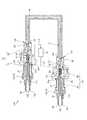
図1は、本実施形態の伝送装置を表す概略構成図である。本実施形態において、図1に示すように、伝送装置100は、光ファイバ11と、配管12と、2つの光コネクタ10(入射側光コネクタ13、出射側光コネクタ14)と、循環装置15とを備えている。 FIG. 1 is a schematic configuration diagram showing a transmission device of the present embodiment. In the present embodiment, as shown in FIG. 1, thetransmission device 100 includes anoptical fiber 11, apipe 12, two optical connectors 10 (incident sideoptical connector 13, exit side optical connector 14), and acirculation device 15. It has.

光ファイバ11は、ガラス製のコアの外側にガラス製のクラッドが設けられる素線11a(図3等参照)と、この素線11aを被覆する樹脂製の被覆部11b(図3等参照)とから構成されている。 Theoptical fiber 11 includes awire 11a in which a glass clad is provided on the outside of a glass core (see FIG. 3 and the like) and aresin covering portion 11b (see FIG. 3 and the like) that covers thewire 11a. It is composed of.

光コネクタ10は、光ファイバ11の両端に接続される。以下、光ファイバ11の基端部11r側に接続される光コネクタ10を入射側光コネクタ13とし、光ファイバ11の先端部11t側に接続される光コネクタ10を出射側光コネクタ14とする。なお、光ファイバ11の基端部11rは、光ファイバ11に光が入射する部分である。また、光ファイバ11の先端部11tは、光ファイバ11から光が出射する部分である。 Theoptical connector 10 is connected to both ends of theoptical fiber 11. Hereinafter, theoptical connector 10 connected to thebase end portion 11r side of theoptical fiber 11 is referred to as an incident sideoptical connector 13, and theoptical connector 10 connected to thetip end portion 11t side of theoptical fiber 11 is referred to as an exit sideoptical connector 14. Thebase end portion 11r of theoptical fiber 11 is a portion where light is incident on theoptical fiber 11. Further, thetip portion 11t of theoptical fiber 11 is a portion where light is emitted from theoptical fiber 11.

入射側光コネクタ13は、基端部13rに図示しない光源(例えば、レーザ発振器)が接続される。入射側光コネクタ13は、先端部13tから内部に光ファイバ11の基端部11rが挿入される。入射側光コネクタ13は、先端部13tにおいて光ファイバ11の基端部11rを支持する。入射側光コネクタ13は、内部に後述する流通部23を有する。 A light source (for example, a laser oscillator) (not shown) is connected to theproximal end portion 13r of the incident sideoptical connector 13. Thebase end portion 11r of theoptical fiber 11 is inserted into the incident sideoptical connector 13 from thetip portion 13t. The incident sideoptical connector 13 supports thebase end portion 11r of theoptical fiber 11 at thetip end portion 13t. The incident sideoptical connector 13 has adistribution unit 23 described later inside.

出射側光コネクタ14は、基端部14rから内部に光ファイバ11の先端部11tが挿入される。出射側光コネクタ14は、基端部14rにおいて光ファイバ11の先端部11tを支持する。出射側光コネクタ14は、先端部14tに図示しない加工装置(例えば、レーザ切断装置)が接続される。出射側光コネクタ14は、内部に後述する流通部23を有する。 Thetip end portion 11t of theoptical fiber 11 is inserted into the exit sideoptical connector 14 from thebase end portion 14r. The emission sideoptical connector 14 supports thetip end portion 11t of theoptical fiber 11 at thebase end portion 14r. A processing device (for example, a laser cutting device) (not shown) is connected to thetip portion 14t of the light emitting sideoptical connector 14. The emission sideoptical connector 14 has adistribution unit 23 described later inside.

配管12は、光ファイバ11のうち2つの光コネクタ10から露出した部分を囲うように設けられる。配管12は、基端部12rが入射側光コネクタ13に接続され、先端部12tが出射側光コネクタ14に接続される。配管12は、内部に流動部44が形成される。冷却媒体流動部44には、光ファイバ11が配置される。配管12は、入射側光コネクタ13と出射側光コネクタ14との間で冷却媒体を流通させる。本実施形態において、冷却媒体としては、例えば冷却水が用いられるが、これに限定されず、他の媒体であってもよい。 Thepipe 12 is provided so as to surround a portion of theoptical fiber 11 exposed from the twooptical connectors 10. In thepipe 12, thebase end portion 12r is connected to the incident sideoptical connector 13, and thetip end portion 12t is connected to the emission sideoptical connector 14. Aflow portion 44 is formed inside thepipe 12. Anoptical fiber 11 is arranged in the coolingmedium flow unit 44. Thepipe 12 circulates the cooling medium between the incident sideoptical connector 13 and the outgoing sideoptical connector 14. In the present embodiment, for example, cooling water is used as the cooling medium, but the cooling medium is not limited to this, and other media may be used.

循環装置15は、配管12とは別個に入射側光コネクタ13及び出射側光コネクタ14の流通部23同士を接続し、入射側光コネクタ13及び出射側光コネクタ14の流通部23と配管12とを含む流路を介して冷却媒体を循環させる。循環装置15は、供給経路L1及び排出経路L2に接続される。循環装置15は、排出経路L2から排出された冷却媒体を供給経路L1に供給する。供給経路L1は、出射側光コネクタ14の第1給排部24に接続される。排出経路L2は、出射側光コネクタ14の第1給排部24に接続される。 Thecirculation device 15 connects theflow sections 23 of the incident sideoptical connector 13 and the exit sideoptical connector 14 separately from thepipe 12, and connects theflow sections 23 and thepipe 12 of the incident sideoptical connector 13 and the exit sideoptical connector 14. The cooling medium is circulated through the flow path containing the above. Thecirculation device 15 is connected to the supply path L1 and the discharge path L2. Thecirculation device 15 supplies the cooling medium discharged from the discharge path L2 to the supply path L1. The supply path L1 is connected to the first supply /discharge unit 24 of the emission sideoptical connector 14. The discharge path L2 is connected to the first supply /discharge portion 24 of the emission sideoptical connector 14.

入射側光コネクタ13と出射側光コネクタ14は、同様の構成をなすものである。以下の説明では、入射側光コネクタ13と出射側光コネクタ14との対応する構成については、同一の符号を付して説明する。なお、光コネクタ10を入射側光コネクタ13として使用する場合と、光コネクタ10を出射側光コネクタ14として使用する場合とでは、光ファイバ11と配管12と連結配管16の接続部分が逆になる。以下、光コネクタ10の説明については、出射側光コネクタ14を例に挙げて説明する。 The incident sideoptical connector 13 and the outgoing sideoptical connector 14 have the same configuration. In the following description, the corresponding configurations of the incident sideoptical connector 13 and the outgoing sideoptical connector 14 will be described with the same reference numerals. The connection portion of theoptical fiber 11, thepipe 12, and the connecting pipe 16 is reversed between the case where theoptical connector 10 is used as the incident sideoptical connector 13 and the case where theoptical connector 10 is used as the exit sideoptical connector 14. .. Hereinafter, the description of theoptical connector 10 will be described by taking the emission sideoptical connector 14 as an example.

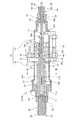
図2は、本実施形態の光コネクタを表す断面図、図3は、図2のIII−III断面図、図4は、図2のIV−IV断面図である。また、図5は、図2のV−V断面図である。 FIG. 2 is a cross-sectional view showing the optical connector of the present embodiment, FIG. 3 is a sectional view taken along line III-III of FIG. 2, and FIG. 4 is a sectional view taken along line IV-IV of FIG. Further, FIG. 5 is a sectional view taken along line VV of FIG.

図2から図4に示すように、出射側光コネクタ14は、ハウジング21と、固定部材22と、流通部23と、第1給排部24と、第2給排部25と、バイパス流路26とを備える。 As shown in FIGS. 2 to 4, the exit sideoptical connector 14 includes ahousing 21, afixing member 22, adistribution section 23, a first supply /discharge section 24, a second supply /discharge section 25, and a bypass flow path. It includes 26.

ハウジング21は、光ファイバ11を収容する。ハウジング21は、長尺の円筒形状をなし、長手方向の中間部に位置する本体部31と、長手方向の先端部14t側に位置する第1連結部32と、長手方向の基端部14r側に位置する第2連結部33とから構成されている。本体部31は、最大の内径が確保されている。第1連結部32は、本体部31の内径より小さい内径が確保され、先細形状をなしている。第2連結部33は、第1連結部32の内径より小さい内径が確保され、先細形状をなし、外部連結部としての連結孔33aが形成されている。なお、ハウジング21は、本体部31と第1連結部32と第2連結部33とを3分割として構成してもよく、また、4部材以上に分割してもよい。 Thehousing 21 houses theoptical fiber 11. Thehousing 21 has a long cylindrical shape, and has amain body portion 31 located in the middle portion in the longitudinal direction, a first connectingportion 32 located on thetip portion 14t side in the longitudinal direction, and abase end portion 14r side in the longitudinal direction. It is composed of a second connecting portion 33 located at. Themain body 31 has a maximum inner diameter. The first connectingportion 32 has an inner diameter smaller than the inner diameter of themain body portion 31 and has a tapered shape. The second connecting portion 33 has an inner diameter smaller than the inner diameter of the first connectingportion 32, has a tapered shape, and has a connectinghole 33a as an external connecting portion. Thehousing 21 may be configured by dividing themain body 31, the first connectingportion 32, and the second connecting portion 33 into three parts, or may divide thehousing 21 into four or more members.

ハウジング21は、内部に光ファイバ11を固定する固定部材22が配置されている。固定部材22は、ハウジング21の内面に支持される第1スリーブ34と、第1スリーブ34の内面に支持される第2スリーブ35と、第2スリーブ35の内面に支持される第3スリーブ36とから構成されている。ハウジング21と第1スリーブ34との間に円筒形状をなす隙間部37が形成されている。 A fixingmember 22 for fixing theoptical fiber 11 is arranged inside thehousing 21. The fixingmember 22 includes afirst sleeve 34 supported on the inner surface of thehousing 21, asecond sleeve 35 supported on the inner surface of thefirst sleeve 34, and athird sleeve 36 supported on the inner surface of thesecond sleeve 35. It is composed of. Acylindrical gap 37 is formed between thehousing 21 and thefirst sleeve 34.

第1スリーブ34は、円筒形状をなし、大径部34aと小径部34bとを有し、大径部34aの外面がハウジング21の本体部31の内面に嵌合して固定され、小径部34bがハウジング21の第1連結部32の内面に嵌合して固定される。 Thefirst sleeve 34 has a cylindrical shape and has alarge diameter portion 34a and asmall diameter portion 34b. The outer surface of thelarge diameter portion 34a is fitted and fixed to the inner surface of themain body portion 31 of thehousing 21, and thesmall diameter portion 34b is fixed. Is fitted and fixed to the inner surface of the first connectingportion 32 of thehousing 21.

第2スリーブ35は、光ファイバ11を囲う円筒形状をなし、大径部35aと小径部35bとを有し、大径部35aの外面が第1スリーブ34の大径部34aの内面に嵌合して固定される。 Thesecond sleeve 35 has a cylindrical shape surrounding theoptical fiber 11, has alarge diameter portion 35a and asmall diameter portion 35b, and the outer surface of thelarge diameter portion 35a fits into the inner surface of thelarge diameter portion 34a of thefirst sleeve 34. And fixed.

第3スリーブ36は、光ファイバ11の軸方向に延びる棒状をなし、第2スリーブ35の大径部35aの内面に嵌合して固定される。 Thethird sleeve 36 has a rod shape extending in the axial direction of theoptical fiber 11, and is fitted and fixed to the inner surface of thelarge diameter portion 35a of thesecond sleeve 35.

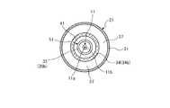
図5に示すように、第3スリーブ36は、V−V断面視において光ファイバ11の円周方向に複数、例えば4つ配置される。なお、第3スリーブ36は、3つ以下であってもよいし、5つ以上であってもよい。複数の第3スリーブ36は、例えば円周方向に等ピッチで配置される。第3スリーブ36は、断面視において径方向の内側の面36aが光ファイバ11の被覆部11bの外周面に当接する。複数の第3スリーブ36によって被覆部11bの外周面が周方向に保持されることで、光ファイバ11が固定される。 As shown in FIG. 5, a plurality of, for example, fourthird sleeves 36 are arranged in the circumferential direction of theoptical fiber 11 in a VV cross-sectional view. The number of thethird sleeve 36 may be three or less, or may be five or more. The plurality ofthird sleeves 36 are arranged at equal pitches in the circumferential direction, for example. In the cross-sectional view of thethird sleeve 36, theinner surface 36a in the radial direction comes into contact with the outer peripheral surface of the coveringportion 11b of theoptical fiber 11. Theoptical fiber 11 is fixed by holding the outer peripheral surface of the coveringportion 11b in the circumferential direction by the plurality ofthird sleeves 36.

また、図5に示すように、第3スリーブ36がV−V断面視において光ファイバ11の周方向に間隔を空けて配置される。このため、第3スリーブ36が設けられない箇所において、第2スリーブ35の内周面35cと、光ファイバ11の外周面との間には、第1連通部43が形成される。本実施形態において、第1連通部43は、V−V断面視において例えば光ファイバ11の周方向に複数、例えば4箇所設けられる。第1連通部43は、例えばスリット状であり、ハウジング21のうち後述する光ファイバ11の先端側の第1流通部41と基端側の第2流通部42との間を連通する。つまり、第1連通部43を介して、光ファイバ11の先端側の第1流通部41から基端側の第2流通部42に冷却媒体が流通するようになっている。第1連通部43は、固定部材22のうち光ファイバ11に面する位置に配置される。この構成により、第1連通部43を流れる冷却媒体が光ファイバ11に接触するため、光ファイバ11を直接的に冷却可能となる。 Further, as shown in FIG. 5, thethird sleeve 36 is arranged at intervals in the circumferential direction of theoptical fiber 11 in the VV cross-sectional view. Therefore, afirst communication portion 43 is formed between the inner peripheral surface 35c of thesecond sleeve 35 and the outer peripheral surface of theoptical fiber 11 at a location where thethird sleeve 36 is not provided. In the present embodiment, thefirst communication portions 43 are provided at a plurality of, for example, four locations in the circumferential direction of theoptical fiber 11, for example, in the VV cross-sectional view. Thefirst communication portion 43 has, for example, a slit shape, and communicates between thefirst circulation portion 41 on the distal end side and thesecond circulation portion 42 on the proximal end side of theoptical fiber 11 described later in thehousing 21. That is, the cooling medium is circulated from thefirst distribution unit 41 on the distal end side of theoptical fiber 11 to thesecond distribution portion 42 on the proximal end side via thefirst communication portion 43. Thefirst communication portion 43 is arranged at a position of the fixingmember 22 facing theoptical fiber 11. With this configuration, the cooling medium flowing through thefirst communication portion 43 comes into contact with theoptical fiber 11, so that theoptical fiber 11 can be directly cooled.

また、図5に示すように、第2スリーブ35の外周面35dには、スリット状の第2連通部45が設けられている。なお、外周面35dは、固定部材22のうち光ファイバ11に面する部分とは異なる部分に設けられる。第2連通部45は、光ファイバ11の軸方向に沿って延びており、第1流通部41と第2流通部42とを連通する。したがって、固定部材22には、第1流通部41と第2流通部42とを連通する連通部として、第1連通部43と第2連通部45とが設けられる。このため、第1連通部43が単独で設けられる構成に比べて、連通部の断面積が大きくなる。第1連通部43及び第2連通部45は、冷却媒体が流れる部分である。したがって、第1連通部43及び第2連通部45が設けられることにより、光ファイバ11の固定部分において冷却媒体の詰まり等を抑制し、冷却媒体の円滑な流通を図ることができる。 Further, as shown in FIG. 5, a slit-shapedsecond communication portion 45 is provided on the outerperipheral surface 35d of thesecond sleeve 35. The outerperipheral surface 35d is provided on a portion of the fixingmember 22 different from the portion facing theoptical fiber 11. Thesecond communication unit 45 extends along the axial direction of theoptical fiber 11 and communicates between thefirst distribution unit 41 and thesecond distribution unit 42. Therefore, the fixingmember 22 is provided with afirst communication section 43 and asecond communication section 45 as communication sections that communicate thefirst communication section 41 and thesecond communication section 42. Therefore, the cross-sectional area of the communicating portion is larger than that in which the first communicatingportion 43 is provided alone. Thefirst communication section 43 and thesecond communication section 45 are portions through which the cooling medium flows. Therefore, by providing thefirst communication portion 43 and thesecond communication portion 45, clogging of the cooling medium at the fixed portion of theoptical fiber 11 can be suppressed, and the cooling medium can be smoothly distributed.

第2連通部45は、第2スリーブ35の周方向に複数、例えば図5における上下左右の4箇所に等ピッチで設けられる。なお、第2連通部45は、第2スリーブ35の周方向に3箇所以下又は5箇所以上に設けられてもよい。本実施形態において、第2連通部45は、第3スリーブ36と対応する位置に設けられる。この場合、第2連通部45は、第3スリーブ36の外周面36bが露出するように設けられる。この構成により、第2連通部45は、第3スリーブ36の外周面36bに面した状態となっている。なお、第2連通部45は、第3スリーブ36の外周面36bが露出しない状態で設けられてもよい。 A plurality ofsecond communication portions 45 are provided in the circumferential direction of thesecond sleeve 35, for example, at four locations on the top, bottom, left, and right in FIG. 5 at equal pitches. Thesecond communication portion 45 may be provided at three or less locations or five or more locations in the circumferential direction of thesecond sleeve 35. In the present embodiment, thesecond communication portion 45 is provided at a position corresponding to thethird sleeve 36. In this case, thesecond communication portion 45 is provided so that the outer peripheral surface 36b of thethird sleeve 36 is exposed. With this configuration, thesecond communication portion 45 is in a state of facing the outer peripheral surface 36b of thethird sleeve 36. Thesecond communication portion 45 may be provided in a state where the outer peripheral surface 36b of thethird sleeve 36 is not exposed.

図2に戻り、ハウジング21は、第1連結部32の内面に第4スリーブ38が固定されている。第4スリーブ38は、円筒形状をなし、内面に円柱形状をなすプローブ39が固定されている。プローブ39は、一端部が第1スリーブ34の小径部34bの端部と接触している。また、プローブ39は、一端部に第2スリーブ35側に突出する円錐形状をなす接合部39aが設けられ、第2スリーブ35の小径部35bとの間に隙間が確保されている。また、ハウジング21は、第2連結部33の連結孔33aの内面に連結配管16の先端部が嵌合して連結されている。 Returning to FIG. 2, in thehousing 21, thefourth sleeve 38 is fixed to the inner surface of the first connectingportion 32. Thefourth sleeve 38 has a cylindrical shape, and aprobe 39 having a cylindrical shape is fixed to the inner surface thereof. One end of theprobe 39 is in contact with the end of thesmall diameter portion 34b of thefirst sleeve 34. Further, theprobe 39 is provided with a conicaljoint portion 39a protruding toward thesecond sleeve 35 at one end, and a gap is secured between theprobe 39 and thesmall diameter portion 35b of thesecond sleeve 35. Further, thehousing 21 is connected by fitting the tip end portion of the connecting pipe 16 to the inner surface of the connectinghole 33a of the second connecting portion 33.

光ファイバ11は、先端部11tが連結配管16からハウジング21の内部に挿入されている。光ファイバ11は、素線11aと被覆部11bとから構成され、被覆部11bが第2スリーブ35の小径部35bの中間位置まで延出され、素線11aがプローブ39まで延出されている。光ファイバ11は、被覆部11bが第3スリーブ36内に挿入されて固定支持され、素線11aの先端部がプローブ39の接合部39aに接触して融着接合されている。また、上述したように、第2スリーブ35の第2連通部45を介して、第1流通部41と第2流通部42とが連通されている。このため、第2連通部45を介して、光ファイバ11の先端側の第1流通部41から基端側の第2流通部42に冷却媒体が流通し、当該冷却媒体により第2スリーブ35が冷却されるようになっている。 Thetip portion 11t of theoptical fiber 11 is inserted into thehousing 21 from the connecting pipe 16. Theoptical fiber 11 is composed of awire 11a and a coveringportion 11b, the coveringportion 11b is extended to an intermediate position of thesmall diameter portion 35b of thesecond sleeve 35, and thewire 11a is extended to theprobe 39. In theoptical fiber 11, the coveringportion 11b is inserted into thethird sleeve 36 and fixedly supported, and the tip end portion of thewire 11a is brought into contact with the joiningportion 39a of theprobe 39 to be fused and joined. Further, as described above, thefirst distribution unit 41 and thesecond distribution unit 42 are communicated with each other via thesecond communication unit 45 of thesecond sleeve 35. Therefore, the cooling medium flows from thefirst distribution section 41 on the distal end side to thesecond distribution section 42 on the proximal end side via thesecond communication portion 45, and the cooling medium causes thesecond sleeve 35 to flow. It is designed to be cooled.

流通部23は、ハウジング21内で固定部材22に支持される光ファイバ11の外側に設けられている。流通部23は、固定部材22に対して光ファイバ11の軸方向における先端側に設けられる第1流通部41と、固定部材22に対して光ファイバ11の軸方向における基端側に設けられる第2流通部42とを有する。 Thedistribution unit 23 is provided inside thehousing 21 on the outside of theoptical fiber 11 supported by the fixingmember 22. Thedistribution unit 23 is provided on thefirst distribution unit 41 provided on the distal end side of theoptical fiber 11 in the axial direction with respect to the fixingmember 22, and on the proximal end side of theoptical fiber 11 in the axial direction with respect to the fixingmember 22. It has twodistribution units 42.

第1流通部41は、第1スリーブ34と第2スリーブ35の大径部35aと第3スリーブ36とプローブ39とにより区画された空間である。第2流通部42は、ハウジング21の本体部31及び第2連結部33と第1スリーブ34と第2スリーブ35と第3スリーブ36とにより区画された空間である。なお、第1流通部41と第2流通部42の間には、光ファイバ11を固定支持する第3スリーブ36が設けられる。上述したように、第3スリーブ36の第1連通部43を介して、第1流通部41と第2流通部42とが連通されている。このため、第1連通部43を介して、光ファイバ11の先端側の第1流通部41から基端側の第2流通部42に冷却媒体が流通し、当該冷却媒体により光ファイバ11の固定支持部が冷却されるようになっている。また、第3スリーブ36は、上述したように、外周面36bが第2連通部45に露出した構成となっている。このため、第2連通部45を流通する冷却媒体により、第3スリーブ36が冷却されるようになっている。 Thefirst distribution section 41 is a space partitioned by thelarge diameter portion 35a of thefirst sleeve 34 and thesecond sleeve 35, thethird sleeve 36, and theprobe 39. Thesecond distribution section 42 is a space partitioned by themain body section 31 of thehousing 21, the second connecting section 33, thefirst sleeve 34, thesecond sleeve 35, and thethird sleeve 36. Athird sleeve 36 for fixing and supporting theoptical fiber 11 is provided between thefirst distribution unit 41 and thesecond distribution unit 42. As described above, thefirst distribution unit 41 and thesecond distribution unit 42 are communicated with each other via thefirst communication unit 43 of thethird sleeve 36. Therefore, the cooling medium flows from thefirst distribution section 41 on the distal end side to thesecond distribution section 42 on the proximal end side via thefirst communication section 43, and theoptical fiber 11 is fixed by the cooling medium. The support is designed to be cooled. Further, as described above, thethird sleeve 36 has a configuration in which the outer peripheral surface 36b is exposed to thesecond communication portion 45. Therefore, thethird sleeve 36 is cooled by the cooling medium flowing through thesecond communication portion 45.

第2流通部42は、拡径部42aを有する。拡径部42aは、第1連通部43及び第2連通部45に接続される側に設けられている。この構成により、第2流通部42は、拡径部42aにおいて冷却媒体の流路抵抗が低減される。このため、第1連通部43及び第2連通部45と第2流通部42との間で冷却媒体を円滑に流通させることができる。 Thesecond distribution section 42 has a diameter-expandedsection 42a. Theenlarged diameter portion 42a is provided on the side connected to thefirst communication portion 43 and thesecond communication portion 45. With this configuration, in thesecond flow section 42, the flow path resistance of the cooling medium is reduced in thediameter expansion section 42a. Therefore, the cooling medium can be smoothly distributed between thefirst communication unit 43, thesecond communication unit 45, and thesecond distribution unit 42.

配管12と光ファイバ11との間に冷却媒体流動部44が確保されている。第2流通部42は、ハウジング21に接続される配管12の冷却媒体流動部44に連通される。 A coolingmedium flow unit 44 is secured between thepipe 12 and theoptical fiber 11. Thesecond distribution section 42 communicates with the coolingmedium flow section 44 of thepipe 12 connected to thehousing 21.

第1給排部24及び第2給排部25は、ハウジング21の流通部23に対して冷却媒体の給排を行う。第1給排部24は、ハウジング21の本体部31のうち光ファイバ11の軸線方向について側部に配置される側部接続部31aを有する。第2給排部25は、ハウジング21のうち第2連結部33側に配置され、配管12に接続される。 The first supply /discharge section 24 and the second supply /discharge section 25 supply / discharge the cooling medium to thedistribution section 23 of thehousing 21. The first supply /discharge portion 24 has a sideportion connecting portion 31a arranged on the side portion of themain body portion 31 of thehousing 21 in the axial direction of theoptical fiber 11. The second supply /discharge portion 25 is arranged on the second connecting portion 33 side of thehousing 21 and is connected to thepipe 12.

出射側光コネクタ14において、第1給排部24は、第1流通部41に冷却媒体を供給する給排部として機能する。また、第2給排部25は、第2流通部42から冷却媒体を排出する給排部として機能する。なお、入射側光コネクタ13において、第1給排部24は、第1流通部41から冷却媒体を排出する給排部として機能する。また、第2給排部25は、第2流通部42に冷却媒体を供給する給排部として機能する。 In the light emitting sideoptical connector 14, the first supply /discharge unit 24 functions as a supply / discharge unit that supplies a cooling medium to thefirst distribution unit 41. Further, the second supply /discharge unit 25 functions as a supply / discharge unit that discharges the cooling medium from thesecond distribution unit 42. In the incident sideoptical connector 13, the first supply /discharge unit 24 functions as a supply / discharge unit that discharges the cooling medium from thefirst distribution unit 41. Further, the second supply /discharge unit 25 functions as a supply / discharge unit that supplies a cooling medium to thesecond distribution unit 42.

バイパス流路26は、上記の第1連通部43及び第2連通部45とは別個に設けられ、ハウジング21の外部を経由して第1流通部41と第2流通部42との間を接続する。バイパス流路26は、第1連通部43及び第2連通部45を迂回するように設けられる。バイパス流路26が設けられることにより、第1流通部41及び第2流通部42への冷却媒体の圧力を抑制しつつ、第1連通部43及び第2連通部45に冷却媒体を流通させることができる。バイパス流路26は、第1流通部41に接続される第1接続部分26aと、第2流通部42に接続される第2接続部分26bとを有する。第1接続部分26aは、第1連通部43の端部に対応する位置に配置される。また、第1接続部分26aは、光ファイバ11の軸方向について、第1給排部24に対応する位置に配置される。このため、出射側光コネクタ14の外形において対応する位置に突出部分が形成されることで、外形上のバランスが確保される。また、第2接続部分26bは、第2流通部42のうち拡径部42aよりも第2連結部33側の位置に配置される。なお、本実施形態において、バイパス流路26は、設けられなくてもよい。 Thebypass flow path 26 is provided separately from thefirst communication section 43 and thesecond communication section 45, and connects between thefirst distribution section 41 and thesecond distribution section 42 via the outside of thehousing 21. To do. Thebypass flow path 26 is provided so as to bypass thefirst communication portion 43 and thesecond communication portion 45. By providing thebypass flow path 26, the cooling medium is circulated through thefirst communication section 43 and thesecond communication section 45 while suppressing the pressure of the cooling medium on thefirst communication section 41 and thesecond communication section 42. Can be done. Thebypass flow path 26 has afirst connection portion 26a connected to thefirst distribution section 41 and asecond connection portion 26b connected to thesecond distribution section 42. Thefirst connection portion 26a is arranged at a position corresponding to the end portion of thefirst communication portion 43. Further, thefirst connection portion 26a is arranged at a position corresponding to the first supply /discharge portion 24 in the axial direction of theoptical fiber 11. Therefore, the balance on the outer shape is ensured by forming the protruding portion at the corresponding position on the outer shape of the light emitting sideoptical connector 14. Further, the second connectingportion 26b is arranged at a position on the second connecting portion 33 side of thesecond distribution portion 42 with respect to theenlarged diameter portion 42a. In this embodiment, thebypass flow path 26 may not be provided.

本実施形態において、循環装置15は、出射側光コネクタ14の第1給排部24と、入射側光コネクタ13の第1給排部24とを接続する。また、配管12は、出射側光コネクタ14の第2給排部25と、入射側光コネクタ13の第2給排部25とを接続する。このため、入射側光コネクタ13、循環装置15、出射側光コネクタ14、及び配管12からなる一系統の流路が形成される。このため、光ファイバ11の全体を確実に冷却することが可能となっている。 In the present embodiment, thecirculation device 15 connects the first supply /discharge unit 24 of the emission sideoptical connector 14 and the first supply /discharge unit 24 of the incident sideoptical connector 13. Further, thepipe 12 connects the second supply /discharge section 25 of the light emitting sideoptical connector 14 and the second supply /discharge section 25 of the incident sideoptical connector 13. Therefore, a system of flow paths including the incident sideoptical connector 13, thecirculation device 15, the exit sideoptical connector 14, and thepipe 12 is formed. Therefore, it is possible to reliably cool the entireoptical fiber 11.

また、循環装置15は、冷却媒体の温度の調整に加えて、流量及び圧力に関する調整を行う。温度については、例えば上記固定部材22の温度及び配管12を流れる冷却媒体の温度を測定し、測定結果が所定の閾値を超えないように冷却媒体の温度を調整することができる。また、流量及び圧力については、例えば循環装置15に流れ込む冷却媒体の流量と、バイパス流路26を流れる流路との差を算出し、当該算出結果が第1連通部43及び第2連通部45を流れる冷却媒体の流量であると推定する。循環装置15は、この算出結果に基づいて冷却媒体の流量及び圧力を調整する。 Further, thecirculation device 15 adjusts the flow rate and the pressure in addition to adjusting the temperature of the cooling medium. Regarding the temperature, for example, the temperature of the fixingmember 22 and the temperature of the cooling medium flowing through thepipe 12 can be measured, and the temperature of the cooling medium can be adjusted so that the measurement result does not exceed a predetermined threshold value. Regarding the flow rate and pressure, for example, the difference between the flow rate of the cooling medium flowing into thecirculation device 15 and the flow path flowing through thebypass flow path 26 is calculated, and the calculation results are thefirst communication section 43 and thesecond communication section 45. It is estimated to be the flow rate of the cooling medium flowing through. Thecirculation device 15 adjusts the flow rate and pressure of the cooling medium based on the calculation result.

また、出射側光コネクタ14は、第1給排部24から第1流通部41に供給された冷却媒体を光ファイバ11の軸方向に沿って流動させる案内部材51を有する。案内部材51は、第2スリーブ35の小径部35bにより形成されている。即ち、第2スリーブ35は、大径部35aが第1スリーブ34に固定され、小径部35bがプローブ39側に延出されている。案内部材51としての小径部35bは、第1流通部41に位置し、一端部が大径部35aに支持された片持ち支持となっている。案内部材51としての小径部35bは、外面と第1スリーブ34の内面との間に隙間が確保されると共に、他端部とプローブ39との間に隙間が確保されている。 Further, the emission sideoptical connector 14 has aguide member 51 that allows the cooling medium supplied from the first supply /discharge unit 24 to thefirst distribution unit 41 to flow along the axial direction of theoptical fiber 11. Theguide member 51 is formed by asmall diameter portion 35b of thesecond sleeve 35. That is, in thesecond sleeve 35, thelarge diameter portion 35a is fixed to thefirst sleeve 34, and thesmall diameter portion 35b extends toward theprobe 39 side. Thesmall diameter portion 35b as theguide member 51 is located in thefirst distribution portion 41 and has a cantilever support at one end supported by thelarge diameter portion 35a. In thesmall diameter portion 35b as theguide member 51, a gap is secured between the outer surface and the inner surface of thefirst sleeve 34, and a gap is secured between the other end and theprobe 39.

案内部材51の小径部35bは、第1給排部24と第2給排部25に対して径方向に対向して配置されている。案内部材51の小径部35bは、円筒形状をなし、軸方向の一端部に第1流通部41に連通する第1開口部52が設けられ、軸方向の他端部に第2給排部25に連通する第2開口部53が設けられている。 Thesmall diameter portion 35b of theguide member 51 is arranged so as to face the first supply /discharge portion 24 and the second supply /discharge portion 25 in the radial direction. Thesmall diameter portion 35b of theguide member 51 has a cylindrical shape, afirst opening 52 communicating with thefirst distribution portion 41 is provided at one end in the axial direction, and a second supply /discharge portion 25 is provided at the other end in the axial direction. Asecond opening 53 that communicates with is provided.

以下、本実施形態の伝送装置100における作用について説明する。図1及び図2に示すように、本実施形態の伝送装置100は、例えばレーザ光源が非放射線領域に配置され、レーザ加工装置が高放射線領域に配置される状況下で用いられる。つまり、伝送装置100は、非放射線領域にあるレーザ光源と、高放射線領域にあるレーザ加工装置とを接続する。レーザ光源のレーザ光が伝送装置100の光ファイバ11によりレーザ加工装置に伝送され、レーザ加工装置を遠隔操作することで、レーザ切断作業などを実施することができる。このような使用態様では、高放射線領域でレーザ光を伝送することにより、光ファイバ11の先端部11t側において素線11aが発熱し、被覆部11bの耐熱温度に近づく可能性がある。 Hereinafter, the operation of thetransmission device 100 of the present embodiment will be described. As shown in FIGS. 1 and 2, thetransmission device 100 of the present embodiment is used, for example, in a situation where the laser light source is arranged in a non-radiation region and the laser processing device is arranged in a high radiation region. That is, thetransmission device 100 connects the laser light source in the non-radiation region and the laser processing device in the high radiation region. The laser beam of the laser light source is transmitted to the laser processing apparatus by theoptical fiber 11 of thetransmission apparatus 100, and the laser cutting operation or the like can be performed by remotely operating the laser processing apparatus. In such a usage mode, by transmitting the laser beam in the high radiation region, thewire 11a may generate heat on thetip end portion 11t side of theoptical fiber 11 and approach the heat resistant temperature of the coveringportion 11b.

これに対して、本実施形態に係る循環装置15は、供給経路L1を介して冷却媒体を出射側光コネクタ14の第1給排部24に供給する。出射側光コネクタ14では、第1給排部24に供給された冷却媒体が第1流通部41を流通し、一部が第1連通部43を介して第2流通部42に到達する。また、第1流通部41を流通する冷却媒体の一部は、第2連通部45を介して第2流通部42に到達する。なお、第1流通部41を流通する冷却媒体の一部は、バイパス流路26を介して第2流通部42に到達する。 On the other hand, thecirculation device 15 according to the present embodiment supplies the cooling medium to the first supply /discharge unit 24 of the exit sideoptical connector 14 via the supply path L1. In the emission sideoptical connector 14, the cooling medium supplied to the first supply /discharge unit 24 circulates through thefirst distribution unit 41, and a part of the cooling medium reaches thesecond distribution unit 42 via thefirst communication unit 43. Further, a part of the cooling medium flowing through thefirst distribution unit 41 reaches thesecond distribution unit 42 via thesecond communication unit 45. A part of the cooling medium flowing through thefirst distribution section 41 reaches thesecond distribution section 42 via thebypass flow path 26.

このように、冷却媒体が第1流通部41、第1連通部43、第2流通部42を流動することで、光ファイバ11が直接的に冷却される。また、第1連通部43を流れる冷却媒体により、光ファイバ11が直接冷却されることに加えて、第3スリーブ36についても冷却される。このため、光ファイバ11のうち第3スリーブ36に支持された部分は、当該第3スリーブ36によって間接的に冷却されることになる。 In this way, the cooling medium flows through thefirst distribution unit 41, thefirst communication unit 43, and thesecond distribution unit 42, so that theoptical fiber 11 is directly cooled. Further, in addition to directly cooling theoptical fiber 11 by the cooling medium flowing through thefirst communication portion 43, thethird sleeve 36 is also cooled. Therefore, the portion of theoptical fiber 11 supported by thethird sleeve 36 is indirectly cooled by thethird sleeve 36.

更に、冷却媒体が第1流通部41、第2連通部45、第2流通部42を流動することで、第2スリーブ35が冷却される。また、本実施形態では、第2連通部45が第3スリーブ36の外周面36bを露出するように形成されるため、冷却媒体が第2連通部45を流通することで、第3スリーブ36が冷却される。このため、第2スリーブ35及び第3スリーブ36を介して光ファイバ11が間接的に冷却されることになる。 Further, the cooling medium flows through thefirst distribution unit 41, thesecond communication unit 45, and thesecond distribution unit 42, so that thesecond sleeve 35 is cooled. Further, in the present embodiment, since thesecond communication portion 45 is formed so as to expose the outer peripheral surface 36b of thethird sleeve 36, the cooling medium flows through thesecond communication portion 45, so that thethird sleeve 36 is formed. It is cooled. Therefore, theoptical fiber 11 is indirectly cooled via thesecond sleeve 35 and thethird sleeve 36.

また、本実施形態において第1流通部41及び第2流通部42に比べて第1連通部43が狭隘である。これに対して、一部の冷却媒体が第1連通部43及び第2連通部45の2つの連通部を介して第2流通部42に到達することで、これらの連通部に冷却媒体を流通させつつ、内圧の上昇を抑制できる。なお、バイパス流路26が設けられることにより、同様に内圧の上昇が抑制される。 Further, in the present embodiment, thefirst communication unit 43 is narrower than thefirst distribution unit 41 and thesecond distribution unit 42. On the other hand, when a part of the cooling medium reaches thesecond communication section 42 via the two communication sections of thefirst communication section 43 and thesecond communication section 45, the cooling medium is distributed to these communication sections. While making it possible, the increase in internal pressure can be suppressed. By providing thebypass flow path 26, the increase in internal pressure is similarly suppressed.

第2流通部42に到達した冷却媒体は、第2給排部25から配管12に流れ込み、配管12の冷却媒体流動部44に沿って流通し、入射側光コネクタ13の第2給排部25に供給される。入射側光コネクタ13では、第2給排部25に供給された冷却媒体が第2流通部42を流通し、一部が第1連通部43を介して第1流通部41に到達する。また、第2流通部42を流通する冷却媒体の一部は、第2連通部45を介して第1流通部41に到達する。なお、第1流通部41を流通する冷却媒体の一部は、バイパス流路26を介して第2流通部42に到達する。このように、入射側光コネクタ13においても同様に、冷却媒体が第2流通部42、第1連通部43、第1流通部41の経路と、第2流通部42、第2連通部45、第1流通部41の経路とを流動することで、光ファイバ11が冷却される。また、一部の冷却媒体がバイパス流路26を介して第2流通部42に到達することで、第1連通部43及び第2連通部45に冷却媒体を流通させつつ、内圧の上昇を抑制できる。 The cooling medium that has reached thesecond distribution section 42 flows into thepipe 12 from the second supply /discharge section 25, flows along the coolingmedium flow section 44 of thepipe 12, and reaches the second supply /discharge section 25 of the incident sideoptical connector 13. Is supplied to. In the incident sideoptical connector 13, the cooling medium supplied to the second supply /discharge unit 25 circulates through thesecond distribution unit 42, and a part of the cooling medium reaches thefirst distribution unit 41 via thefirst communication unit 43. Further, a part of the cooling medium flowing through thesecond distribution unit 42 reaches thefirst distribution unit 41 via thesecond communication unit 45. A part of the cooling medium flowing through thefirst distribution section 41 reaches thesecond distribution section 42 via thebypass flow path 26. As described above, also in the incident sideoptical connector 13, the cooling medium is the path of thesecond distribution unit 42, thefirst communication unit 43, thefirst distribution unit 41, and thesecond distribution unit 42, thesecond communication unit 45, Theoptical fiber 11 is cooled by flowing through the path of thefirst distribution unit 41. Further, by allowing a part of the cooling medium to reach thesecond communication section 42 via thebypass flow path 26, the cooling medium is circulated through thefirst communication section 43 and thesecond communication section 45, and the increase in internal pressure is suppressed. it can.

第1流通部41に到達した冷却媒体は、第1給排部24から排出経路L2に流れ込み、循環装置15に供給される。循環装置15は、排出経路L2から供給された冷却媒体に対して温度調整等を行った後、当該冷却媒体を再び供給経路L1に循環させる。このように、一系統の流路に冷却媒体を流通させることで、光ファイバ11の全体が確実に冷却され、素線11aの温度上昇が抑制される。 The cooling medium that has reached thefirst distribution unit 41 flows from the first supply /discharge unit 24 into the discharge path L2 and is supplied to thecirculation device 15. Thecirculation device 15 adjusts the temperature of the cooling medium supplied from the discharge path L2, and then circulates the cooling medium again in the supply path L1. By passing the cooling medium through the flow path of one system in this way, the entireoptical fiber 11 is surely cooled, and the temperature rise of thewire 11a is suppressed.

以上のように、本実施形態に係る光コネクタ10は、光ファイバ11を収容するハウジング21と、ハウジング21内で光ファイバ11の外周を囲んだ状態で固定する固定部材22と、ハウジング21内において固定部材22に対して光ファイバ11の軸方向の両側に設けられる流通部23と、2つの流通部23のうち一方の流通部23に冷却媒体を供給し他方の流通部23から冷却媒体を排出する第1給排部24及び第2給排部25と、固定部材22のうち光ファイバ11に面する部分に配置され、2つの流通部23を連通する第1連通部43と、固定部材22のうち光ファイバ11に面する部分とは異なる部分に設けられ、2つの流通部23を連通する第2連通部45とを備える。 As described above, theoptical connector 10 according to the present embodiment includes thehousing 21 that houses theoptical fiber 11, the fixingmember 22 that fixes theoptical fiber 11 in thehousing 21 while surrounding the outer periphery of theoptical fiber 11, and the inside of thehousing 21. A cooling medium is supplied to adistribution unit 23 provided on both sides of theoptical fiber 11 in the axial direction with respect to the fixingmember 22, and onedistribution unit 23 of the twodistribution units 23 is supplied, and the cooling medium is discharged from theother distribution unit 23. The first supply /discharge section 24 and the second supply /discharge section 25, and thefirst communication section 43 and the fixingmember 22 which are arranged in the portion of the fixingmember 22 facing theoptical fiber 11 and communicate with the twodistribution sections 23. Asecond communication portion 45, which is provided in a portion different from the portion facing theoptical fiber 11 and communicates with the twodistribution portions 23, is provided.

従って、第1連通部43を流れる冷却媒体により、光ファイバ11のうち固定部材22で固定される部分が直接的に冷却されることになる。このため、冷却効率を向上させることができる。また、第1連通部43とは別個に設けられる第2連通部45を介して第1流通部41から第2流通部42に冷却媒体を迂回させることができるため、第1連通部43が狭隘であっても、流通部23内の圧力の上昇を抑制しつつ、第1連通部43に冷却媒体を流通させることができる。したがって、ハウジング21内に冷却媒体を円滑に流すことができる。また、第2連通部45により固定部材22が冷却されることで、固定部材22を介して光ファイバ11が間接的に冷却される。これにより、光ファイバ11の発熱を抑制して信頼性の向上を図る光コネクタ10が提供される。 Therefore, the portion of theoptical fiber 11 fixed by the fixingmember 22 is directly cooled by the cooling medium flowing through thefirst communication portion 43. Therefore, the cooling efficiency can be improved. Further, since the cooling medium can be bypassed from thefirst distribution unit 41 to thesecond distribution unit 42 via thesecond communication unit 45 provided separately from thefirst communication unit 43, thefirst communication unit 43 is narrow. Even so, the cooling medium can be circulated through thefirst communication unit 43 while suppressing the increase in pressure in thedistribution unit 23. Therefore, the cooling medium can flow smoothly into thehousing 21. Further, the fixingmember 22 is cooled by thesecond communication portion 45, so that theoptical fiber 11 is indirectly cooled via the fixingmember 22. As a result, theoptical connector 10 for suppressing heat generation of theoptical fiber 11 and improving reliability is provided.

本実施形態に係る光コネクタ10において、第2連通部45は、第2スリーブ35の外周面35dに配置される。したがって、第2連通部45を容易に形成することができる。 In theoptical connector 10 according to the present embodiment, thesecond communication portion 45 is arranged on the outerperipheral surface 35d of thesecond sleeve 35. Therefore, thesecond communication portion 45 can be easily formed.

本実施形態に係る光コネクタ10において、第2連通部45は、固定部材22の周方向に複数設けられる。したがって、固定部材22を周方向の複数の位置で冷却することができるため、冷却効率を高めることができる。 In theoptical connector 10 according to the present embodiment, a plurality ofsecond communication portions 45 are provided in the circumferential direction of the fixingmember 22. Therefore, since the fixingmember 22 can be cooled at a plurality of positions in the circumferential direction, the cooling efficiency can be improved.

本実施形態に係る光コネクタ10において、2つの流通部23の一方である第1流通部41は、光ファイバ11の端部を含む部分に設けられ、他方の流通部23である第2流通部42は、第1連通部43及び第2連通部45と接続される部分に拡径部42aを有する。したがって、拡径部42aにおいて冷却媒体の流路抵抗を低減することができるため、第1連通部43及び第2連通部45と第2流通部42との間で冷却媒体を円滑に流通させることができる。 In theoptical connector 10 according to the present embodiment, thefirst distribution unit 41, which is one of the twodistribution units 23, is provided in a portion including the end portion of theoptical fiber 11, and thesecond distribution unit 23 is theother distribution unit 23. 42 has a diameter-expandedportion 42a at a portion connected to thefirst communication portion 43 and thesecond communication portion 45. Therefore, since the flow path resistance of the cooling medium can be reduced in the diameter-expandedportion 42a, the cooling medium can be smoothly circulated between thefirst communication portion 43 and thesecond communication portion 45 and thesecond communication portion 42. Can be done.

本実施形態に係る伝送装置100は、光ファイバ11と、光ファイバ11の基端部11r及び先端部11tをそれぞれ支持し、内部にそれぞれ流通部23を有する光コネクタと、光ファイバ11のうち2つの光コネクタから露出した部分を囲い、2つの光コネクタの流通部23同士を接続する配管12と、配管12とは別個に2つの光コネクタの流通部23同士を接続し、2つの光コネクタの流通部23と配管12とを含む流路を介して冷却媒体を循環させる循環装置15と、を備え、2つの光コネクタのうち少なくとも光ファイバの先端部を支持する出射側光コネクタ14は、上記の光コネクタ10が用いられる。この伝送装置100では、バイパス流路26が設けられることで、流通部23内の圧力の上昇を抑制しつつ、連通部43に冷却媒体を流通させることができる。したがって、配管12内において光ファイバ11に十分な冷却能力を有する冷却媒体を必要な流量だけ確保することができる。また、出射側光コネクタ14を高放射線領域で用いる場合等において、出射側光コネクタ14に接続される光ファイバ11の発熱を抑制することができる。 Thetransmission device 100 according to the present embodiment supports theoptical fiber 11, thebase end portion 11r and thetip end portion 11t of theoptical fiber 11, respectively, and has anoptical connector 23 inside, respectively, and two of theoptical fibers 11. Apipe 12 that surrounds the part exposed from the two optical connectors and connects thedistribution parts 23 of the two optical connectors, and apipe 12 that connects thedistribution parts 23 of the two optical connectors separately from thepipe 12 to connect the two optical connectors. The exit sideoptical connector 14 including thecirculation device 15 for circulating the cooling medium through the flow path including thedistribution unit 23 and thepipe 12 and supporting at least the tip end portion of the optical fiber among the two optical connectors is described above.Optical connector 10 is used. In thetransmission device 100, by providing thebypass flow path 26, the cooling medium can be circulated through thecommunication section 43 while suppressing the increase in pressure in theflow section 23. Therefore, it is possible to secure a cooling medium having a sufficient cooling capacity for theoptical fiber 11 in thepipe 12 by a required flow rate. Further, when the light emitting sideoptical connector 14 is used in a high radiation region or the like, heat generation of theoptical fiber 11 connected to the light emitting sideoptical connector 14 can be suppressed.

本実施形態に係る伝送装置100において、2つの光コネクタの両方について、上記の光コネクタ10が用いられ、循環装置15は、一方の光コネクタ10の第1給排部24と、他方の光コネクタ10の第2給排部25とを接続し、配管12は、一方の光コネクタ10の第2給排部25と、他方の光コネクタ10の第1給排部24とを接続する。これにより、一方の光コネクタ10、循環装置15、他方の光コネクタ10、及び配管12からなる一系統の流路が形成される。このため、光ファイバ11の全体を確実に冷却することが可能となる。 In thetransmission device 100 according to the present embodiment, the above-mentionedoptical connector 10 is used for both of the two optical connectors, and thecirculation device 15 has the first supply /discharge unit 24 of oneoptical connector 10 and the other optical connector. The second supply /discharge section 25 of 10 is connected, and thepipe 12 connects the second supply /discharge section 25 of oneoptical connector 10 and the first supply /discharge section 24 of the otheroptical connector 10. As a result, a system of flow paths including oneoptical connector 10, acirculation device 15, the otheroptical connector 10, and apipe 12 is formed. Therefore, it is possible to reliably cool the entireoptical fiber 11.

本発明の技術範囲は上記実施形態に限定されるものではなく、本発明の趣旨を逸脱しない範囲で適宜変更を加えることができる。例えば、上述した実施形態では、ハウジング21に配管12を連結した構成を例に挙げて説明したが、これに限定されず、例えば連結配管16を介してハウジング21に配管12を連結する構成としてもよい。 The technical scope of the present invention is not limited to the above-described embodiment, and modifications can be made as appropriate without departing from the spirit of the present invention. For example, in the above-described embodiment, the configuration in which thepipe 12 is connected to thehousing 21 has been described as an example, but the present invention is not limited to this, and for example, the configuration in which thepipe 12 is connected to thehousing 21 via the connecting pipe 16 is also possible. Good.

また、上記した実施形態において、配管12の内径を調整することにより、光コネクタ10の流通部23内の冷却媒体の圧力を調整するようにしてもよい。ここで、配管12の内径をr、配管12の長さをL、冷却媒体の流速をv、冷却媒体の密度をρ、配管12の管摩擦係数をλとすると、光コネクタ10の流通部23内の耐圧P及び冷却媒体の流量の目標値Qが以下の式1及び式2を満たすように各部が設計される。 Further, in the above-described embodiment, the pressure of the cooling medium in thedistribution section 23 of theoptical connector 10 may be adjusted by adjusting the inner diameter of thepipe 12. Here, assuming that the inner diameter of thepipe 12 is r, the length of thepipe 12 is L, the flow velocity of the cooling medium is v, the density of the cooling medium is ρ, and the pipe friction coefficient of thepipe 12 is λ, thecirculation portion 23 of theoptical connector 10 Each part is designed so that the withstand voltage P and the target value Q of the flow rate of the cooling medium satisfy the following equations 1 and 2.

P>λLρv/2r ・・・(式1)
Q=πrv ・・・(式2)
P> λLρv2 / 2r ・ ・ ・ (Equation 1)
Q = πr2 v ・ ・ ・ (Equation 2)

上記式1及び式2により、例えば冷却媒体の流量3L/minを確保する場合、ファイバ伝送距離(配管12の長さL)を100mとし、光コネクタ10の流通部23内の耐圧Pを1MPaとすると、配管12の内径はΦ8mm程度となる。 According to the above formulas 1 and 2, for example, when the flow rate of the cooling medium is secured at 3 L / min, the fiber transmission distance (length L of the pipe 12) is set to 100 m, and the withstand voltage P in theflow section 23 of theoptical connector 10 is set to 1 MPa. Then, the inner diameter of thepipe 12 becomes about Φ8 mm.

また、上述した実施形態では、冷却媒体として冷却水を適用したが、冷却媒体は冷却水に限定されるものではなく、例えば、空気でもよい。 Further, in the above-described embodiment, the cooling water is applied as the cooling medium, but the cooling medium is not limited to the cooling water, and may be, for example, air.

また、上述した実施形態では、入射側光コネクタ13と出射側光コネクタ14を同じ構成のものとしたが、異なる構成のものであってもよい。 Further, in the above-described embodiment, the incident sideoptical connector 13 and the outgoing sideoptical connector 14 have the same configuration, but they may have different configurations.

10 光コネクタ
11 光ファイバ
11a 素線
11b 被覆部
11r,12r,13r,14r 基端部
11t,12t,13t,14t 先端部
12 配管
13 入射側光コネクタ
14 出射側光コネクタ
15 循環装置
16 連結配管
21 ハウジング
22 固定部材
23 流通部
24 第1給排部
25 第2給排部
26 バイパス流路
26a 第1接続部分
26b 第2接続部分
31 本体部
31a 側部接続部
32 第1連結部
33 第2連結部
33a 連結孔
34 第1スリーブ
34a,35a 大径部
34b,35b 小径部
35 第2スリーブ
35c 内周面
35d,36b 外周面
36 第3スリーブ
36a 面
37 隙間部
38 第4スリーブ
39 プローブ
39a 接合部
41 第1流通部
42 第2流通部
42a 拡径部
43 第1連通部
44 流動部
45 第2連通部
51 案内部材
52 第1開口部
53 第2開口部
100 伝送装置
L1 供給経路
L2 排出経路
10Optical connector 11Opticalfiber 11a Wire11b Coating part 11r, 12r, 13r, 14rBase end part 11t, 12t, 13t,14t Tip part 12Piping 13 Incident sideoptical connector 14 Outgoing sideoptical connector 15 Circulator 16Connecting pipe 21Housing 22 Fixingmember 23Distribution part 24 1st supply /discharge part 25 2nd supply /discharge part 26Bypass flow path 26a1st connection part 26b2nd connection part 31Main body 31aSide connection part 32 1st connection part 332nd connection Part33a Connecting hole 34First sleeve 34a, 35aLarge diameter part 34b, 35bSmall diameter part 35 Second sleeve 35c Innerperipheral surface 35d, 36b Outerperipheral surface 36Thirdsleeve 36a Surface 37Gap 38Fourth sleeve 39Probe 39a Joint 411st distribution section 422nd distribution section 42aDiameter expansion section 431st communication section 44Flow section 452nd communication section 51Guide member 52 1st opening 532nd opening 100 Transmission device L1 Supply path L2 Discharge path

Claims (10)

Translated fromJapanese
光ファイバを収容するハウジングと、
前記ハウジング内で前記光ファイバの外周を囲んだ状態で固定する固定部材と、
前記ハウジング内において前記固定部材に対して前記光ファイバの軸方向の両側に設けられる流通部と、
2つの前記流通部のうち一方の前記流通部に冷却媒体を供給する、または他方の前記流通部から前記冷却媒体を排出する給排部と、
前記固定部材のうち前記光ファイバに面する部分に配置され、2つの前記流通部を連通する第1連通部と、
前記固定部材のうち前記光ファイバに面する部分とは異なる部分に設けられ、2つの前記流通部を連通する第2連通部と
を備える光コネクタ。
A housing that houses an optical fiber
A fixing member fixed in the housing so as to surround the outer periphery of the optical fiber,
In the housing, distribution portions provided on both sides of the optical fiber in the axial direction with respect to the fixing member, and
A supply / discharge unit that supplies a cooling medium to one of the two distribution units or discharges the cooling medium from the other distribution unit.
A first communication portion, which is arranged in a portion of the fixing member facing the optical fiber and communicates with the two communication portions,
An optical connector provided in a portion of the fixing member different from the portion facing the optical fiber, and provided with a second communicating portion that communicates the two communication portions.
前記第2連通部は、前記固定部材の外周面に配置される
請求項1に記載の光コネクタ。
The optical connector according to claim 1, wherein the second communication portion is arranged on an outer peripheral surface of the fixing member.
前記第2連通部は、前記固定部材の周方向に複数設けられる
請求項1又は請求項2に記載の光コネクタ。
The optical connector according to claim 1 or 2, wherein a plurality of the second communication portions are provided in the circumferential direction of the fixing member.
2つの前記流通部の一方は、前記光ファイバの端部を含む部分に設けられ、
他方の前記流通部は、前記第1連通部及び前記第2連通部と接続される部分に拡径部を有する
請求項1から請求項3のいずれか一項に記載の光コネクタ。
One of the two distribution sections is provided in a portion including the end portion of the optical fiber.
The optical connector according to any one of claims 1 to 3, wherein the other distribution unit has a diameter-expanded portion in a portion connected to the first communication portion and the second communication portion.
前記固定部材は、筒形状であり、前記光ファイバを保持する保持部材を内面に有し、
前記第2連通部は、前記保持部材の一部が露出するように設けられる
請求項1から請求項4のいずれか一項に記載の光コネクタ。
The fixing member has a tubular shape and has a holding member for holding the optical fiber on the inner surface.
The optical connector according to any one of claims 1 to 4, wherein the second communication portion is provided so that a part of the holding member is exposed.
前記給排部は、前記ハウジングのうち前記光ファイバの軸線方向について側部に接続される側部接続部を有する
請求項1から請求項5のいずれか一項に記載の光コネクタ。
The optical connector according to any one of claims 1 to 5, wherein the supply / discharge unit has a side connection portion connected to a side portion of the housing in the axial direction of the optical fiber.
前記第1連通部及び前記第2連通部とは別個に設けられ、前記ハウジングの外部を経由して一方の前記流通部と他方の前記流通部との間を接続するバイパス流路を更に備える
請求項1から請求項6のいずれか一項に記載の光コネクタ。
A claim that is provided separately from the first communication section and the second communication section, and further includes a bypass flow path that connects one of the distribution sections and the other through the outside of the housing. The optical connector according to any one of claims 1 to 6.
光ファイバと、
前記光ファイバの基端部及び先端部をそれぞれ支持し、内部にそれぞれ流通部を有する光コネクタと、
前記光ファイバのうち2つの前記光コネクタから露出した部分を囲い、2つの前記光コネクタの前記流通部同士を接続する配管と、
前記配管とは別個に2つの前記光コネクタの前記流通部同士を接続し、2つの前記光コネクタの前記流通部と前記配管とを含む流路を介して前記冷却媒体を循環させる循環装置と、
を備え、
2つの前記光コネクタのうち少なくとも前記光ファイバの前記先端部を支持する前記光コネクタについて、請求項1から請求項7のいずれか一項に記載の光コネクタが用いられる
伝送装置。
With optical fiber
An optical connector that supports the base end and the tip of the optical fiber and has a distribution part inside, respectively.
A pipe that surrounds two portions of the optical fiber exposed from the optical connector and connects the distribution portions of the two optical connectors,
A circulation device that connects the distribution sections of the two optical connectors separately from the piping and circulates the cooling medium through a flow path including the distribution section and the piping of the two optical connectors.
With
A transmission device in which the optical connector according to any one of claims 1 to 7 is used for the optical connector that supports at least the tip of the optical fiber among the two optical connectors.
2つの前記光コネクタの両方について、請求項1から請求項4のいずれか一項に記載の光コネクタが用いられ、
前記循環装置は、一方の前記光コネクタの前記給排部と、他方の前記光コネクタの前記給排部とを接続し、
前記配管は、一方の前記光コネクタの前記給排部と、他方の前記光コネクタの前記給排部とを接続する
請求項8に記載の伝送装置。
The optical connector according to any one of claims 1 to 4 is used for both of the two optical connectors.
The circulation device connects the supply / discharge portion of one of the optical connectors and the supply / discharge portion of the other optical connector.
The transmission device according to claim 8, wherein the pipe connects the supply / discharge portion of one of the optical connectors and the supply / discharge portion of the other optical connector.
前記配管の内径をr、前記配管の長さをL、前記冷却媒体の流速をv、前記冷却媒体の密度をρ、前記配管の管摩擦係数をλとした場合、前記流通部内の圧力P及び前記冷却媒体の流量の目標値をQが、
P>λLρv/2r ・・・(式1)
q=πrv ・・・(式2)
を満たすように設計される
請求項8又は請求項9に記載の伝送装置。
When the inner diameter of the pipe is r, the length of the pipe is L, the flow velocity of the cooling medium is v, the density of the cooling medium is ρ, and the pipe friction coefficient of the pipe is λ, the pressure P in the flow section and Q is the target value of the flow rate of the cooling medium.
P> λLρv2 / 2r ・ ・ ・ (Equation 1)
q = πr2 v ・ ・ ・ (Equation 2)
The transmission device according to claim 8 or 9, which is designed to satisfy the requirements.
JP2019135238A2019-07-232019-07-23 Optical connectors and transmission equipmentActiveJP7340376B2 (en)

Priority Applications (1)

Application NumberPriority DateFiling DateTitle
JP2019135238AJP7340376B2 (en)2019-07-232019-07-23 Optical connectors and transmission equipment

Applications Claiming Priority (1)

Application NumberPriority DateFiling DateTitle
JP2019135238AJP7340376B2 (en)2019-07-232019-07-23 Optical connectors and transmission equipment

Publications (2)

Publication NumberPublication Date
JP2021018370Atrue JP2021018370A (en)2021-02-15
JP7340376B2 JP7340376B2 (en)2023-09-07

Family

ID=74563626

Family Applications (1)

Application NumberTitlePriority DateFiling Date
JP2019135238AActiveJP7340376B2 (en)2019-07-232019-07-23 Optical connectors and transmission equipment

Country Status (1)

CountryLink
JP (1)JP7340376B2 (en)

Cited By (1)

* Cited by examiner, † Cited by third party
Publication numberPriority datePublication dateAssigneeTitle
WO2023054329A1 (en)*2021-10-012023-04-06三菱重工業株式会社Optical connector

Citations (7)

* Cited by examiner, † Cited by third party
Publication numberPriority datePublication dateAssigneeTitle
JPS60165953A (en)*1984-02-091985-08-29オリンパス光学工業株式会社Safety apparatus of laser beam transmitting means
JPH08220404A (en)*1995-02-101996-08-30Dengensha Mfg Co Ltd YAG laser processing system and cooled optical fiber cable
US5827267A (en)*1992-02-181998-10-27Angeion CorporationCooled multi-fiber medical connector
JP2016080231A (en)*2014-10-152016-05-16三菱電機株式会社 Heat exchanger and refrigeration cycle apparatus equipped with the same
JP2016533543A (en)*2013-10-182016-10-27オプトスカンド エービー Optoelectronic assembly device
JP2020008668A (en)*2018-07-052020-01-16三菱重工業株式会社Optical connector and transmission apparatus
CN210957260U (en)*2019-12-062020-07-07武汉优信技术股份有限公司High-energy optical fiber laser output head with collimation end cap

Patent Citations (7)

* Cited by examiner, † Cited by third party
Publication numberPriority datePublication dateAssigneeTitle
JPS60165953A (en)*1984-02-091985-08-29オリンパス光学工業株式会社Safety apparatus of laser beam transmitting means
US5827267A (en)*1992-02-181998-10-27Angeion CorporationCooled multi-fiber medical connector
JPH08220404A (en)*1995-02-101996-08-30Dengensha Mfg Co Ltd YAG laser processing system and cooled optical fiber cable
JP2016533543A (en)*2013-10-182016-10-27オプトスカンド エービー Optoelectronic assembly device
JP2016080231A (en)*2014-10-152016-05-16三菱電機株式会社 Heat exchanger and refrigeration cycle apparatus equipped with the same
JP2020008668A (en)*2018-07-052020-01-16三菱重工業株式会社Optical connector and transmission apparatus
CN210957260U (en)*2019-12-062020-07-07武汉优信技术股份有限公司High-energy optical fiber laser output head with collimation end cap

Cited By (2)

* Cited by examiner, † Cited by third party
Publication numberPriority datePublication dateAssigneeTitle
WO2023054329A1 (en)*2021-10-012023-04-06三菱重工業株式会社Optical connector
JP2023053684A (en)*2021-10-012023-04-13三菱重工業株式会社 optical connector

Also Published As

Publication numberPublication date
JP7340376B2 (en)2023-09-07

Similar Documents

PublicationPublication DateTitle
US5688222A (en)Endoscopic instrument
JP2020008668A (en)Optical connector and transmission apparatus
JP7190402B2 (en) Optical connector and transmission device
CN104641207B (en) Measuring device housing
JP4954737B2 (en) Optical amplification system, optical fiber laser and optical fiber amplifier using the same
US4532396A (en)Flexible induction brazing wand for hollow tubes
JP6214170B2 (en) Optical connector and optical fiber cable including the same
JP2021018370A (en)Optical connector and transmission apparatus
JP2010190934A (en)Light-guide, light source apparatus and endoscope system
JP6314008B2 (en) Endoscope system
CN106918878B (en) Fiber Relay Unit
JP6484279B2 (en) Optical fiber cable unit
JP5270949B2 (en) LASER LIGHT EMITTING DEVICE AND LASER DEVICE
CN109416447A (en)High-NA photospallation device
JP6444989B2 (en) Endoscope
JP2013506135A (en) Thermal sensor for flexible waveguide
JP7265612B2 (en) Optical fiber cable, optical combiner unit using optical fiber cable, and laser device
JP2018004834A (en)Optical device and laser apparatus
US20240393542A1 (en)Optical connector
JP7297577B2 (en) Connection structure of laser processing equipment
JPH11192240A (en) Laser light transmission device and handpiece
JP2020177216A (en) Fiber optic penetration
WO2023054329A1 (en)Optical connector
US20180284365A1 (en)Optical fiber drawer structure and optical module
JP6045536B2 (en) Endoscope device

Legal Events

DateCodeTitleDescription
A621Written request for application examination

Free format text:JAPANESE INTERMEDIATE CODE: A621

Effective date:20220216

A977Report on retrieval

Free format text:JAPANESE INTERMEDIATE CODE: A971007

Effective date:20221026

A131Notification of reasons for refusal

Free format text:JAPANESE INTERMEDIATE CODE: A131

Effective date:20221101

A521Request for written amendment filed

Free format text:JAPANESE INTERMEDIATE CODE: A523

Effective date:20221212

A131Notification of reasons for refusal

Free format text:JAPANESE INTERMEDIATE CODE: A131

Effective date:20230322

A521Request for written amendment filed

Free format text:JAPANESE INTERMEDIATE CODE: A523

Effective date:20230515

TRDDDecision of grant or rejection written
A01Written decision to grant a patent or to grant a registration (utility model)

Free format text:JAPANESE INTERMEDIATE CODE: A01

Effective date:20230801

A61First payment of annual fees (during grant procedure)

Free format text:JAPANESE INTERMEDIATE CODE: A61

Effective date:20230828

R150Certificate of patent or registration of utility model

Ref document number:7340376

Country of ref document:JP

Free format text:JAPANESE INTERMEDIATE CODE: R150

S111Request for change of ownership or part of ownership

Free format text:JAPANESE INTERMEDIATE CODE: R313115

R350Written notification of registration of transfer

Free format text:JAPANESE INTERMEDIATE CODE: R350


[8]ページ先頭

©2009-2025 Movatter.jp