JP2021017145A - Positioning structure of plate member and backlit license plate - Google Patents
Positioning structure of plate member and backlit license plateDownload PDFInfo
- Publication number
- JP2021017145A JP2021017145AJP2019134256AJP2019134256AJP2021017145AJP 2021017145 AJP2021017145 AJP 2021017145AJP 2019134256 AJP2019134256 AJP 2019134256AJP 2019134256 AJP2019134256 AJP 2019134256AJP 2021017145 AJP2021017145 AJP 2021017145A
- Authority
- JP
- Japan
- Prior art keywords
- plate
- hole
- protrusion
- substrate
- license plate
- Prior art date
- Legal status (The legal status is an assumption and is not a legal conclusion. Google has not performed a legal analysis and makes no representation as to the accuracy of the status listed.)
- Pending
Links
Images


Landscapes
- Vehicle Waterproofing, Decoration, And Sanitation Devices (AREA)
- Planar Illumination Modules (AREA)
Abstract
Translated fromJapaneseDescription
Translated fromJapanese本発明は、板状のプレート部材を基体に対して位置決めするプレート部材の位置決め構造および字光式ナンバープレートに関する。 The present invention relates to a plate member positioning structure for positioning a plate-shaped plate member with respect to a substrate and a character light type license plate.
従来から、ナンバープレートに表示された文字に光を照射して光らせる字光式ナンバープレートがある。特許文献1に記載された従来の字光式ナンバープレートは、車両の登録番号を構成する文字が表示されたナンバープレートと、文字に光を照射するナンバープレート用照明装置とを備えている。ナンバープレート用照明装置は、回路基板、発光ダイオードおよび導光板を有しており、これらはケースに収容されている。 Conventionally, there is a character light type license plate that irradiates the characters displayed on the license plate with light to make them shine. The conventional character light type license plate described in Patent Document 1 includes a license plate on which characters constituting a vehicle registration number are displayed, and a license plate lighting device that irradiates the characters with light. The license plate illuminator has a circuit board, a light emitting diode and a light guide plate, which are housed in a case.
ナンバープレートの上部の左右方向両端部には、ボルトが挿通される第1ボルト挿通孔が形成されており、ケースの上部の左右方向両端部には、上記のボルトが挿通される第2ボルト挿通孔が形成されている。字光式ナンバープレートを車両に取り付ける際には、ナンバープレートの第1ボルト挿通孔およびナンバープレート用照明装置の第2ボルト挿通孔に表側からボルトが挿入され、このボルトが車両に設けられたねじ孔に螺合される。 The first bolt insertion holes through which bolts are inserted are formed at both ends in the left-right direction of the upper part of the license plate, and the second bolt insertion through which the above bolts are inserted is formed at both ends in the left-right direction at the upper part of the case. A hole is formed. When attaching the license plate to the vehicle, a bolt is inserted from the front side into the first bolt insertion hole of the license plate and the second bolt insertion hole of the license plate lighting device, and this bolt is a screw provided on the vehicle. It is screwed into the hole.
しかしながら、特許文献1の字光式ナンバープレートにおいて、ナンバープレートの第1ボルト挿通孔の直径がナンバープレート用照明装置の第2ボルト挿通孔の直径に比べて大きい場合には、ボルトの直径を第2ボルト挿通孔の直径とほぼ同じにしても、第1ボルト挿通孔の内周面とボルトの外周面との間に隙間が生じていた。したがって、この隙間において、ナンバープレートの位置がナンバープレート用照明装置に対してずれるおそれがあった。 However, in the character light type license plate of Patent Document 1, when the diameter of the first bolt insertion hole of the license plate is larger than the diameter of the second bolt insertion hole of the license plate lighting device, the diameter of the bolt is set to the second. Even if the diameter of the 2-bolt insertion hole is almost the same, a gap is formed between the inner peripheral surface of the first bolt insertion hole and the outer peripheral surface of the bolt. Therefore, in this gap, the position of the license plate may shift with respect to the license plate lighting device.
例えば、第1ボルト挿通孔の直径が8mm、第2ボルト挿通孔の直径が6mm、ボルトの直径が6mmであれば、第1ボルト挿通孔および第2ボルト挿通孔のそれぞれの中心を一致させたときに、第1ボルト挿通孔の内周面とボルトの外周面との間に1mmの隙間が生じる。したがって、この場合には、ナンバープレートの位置がナンバープレート用照明装置に対して最大で1mmずれるおそれがあった。 For example, if the diameter of the first bolt insertion hole is 8 mm, the diameter of the second bolt insertion hole is 6 mm, and the diameter of the bolt is 6 mm, the centers of the first bolt insertion hole and the second bolt insertion hole are aligned. Occasionally, a gap of 1 mm is created between the inner peripheral surface of the first bolt insertion hole and the outer peripheral surface of the bolt. Therefore, in this case, the position of the license plate may be displaced by a maximum of 1 mm with respect to the license plate lighting device.
そして、ナンバープレートの位置がナンバープレート用照明装置に対してずれると、ナンバープレートの文字の位置が導光板から照射される光の照射位置に対してずれるため、文字の明るさにむらが生じるおそれがあった。 If the position of the license plate deviates from the license plate lighting device, the position of the characters on the license plate deviates from the irradiation position of the light emitted from the light guide plate, which may cause uneven brightness of the characters. was there.
本発明は上記問題に対処するためになされたものであり、その目的は、プレート部材の基体に対する位置ずれを抑制できる、プレート部材の位置決め構造および字光式ナンバープレートを提供することにある。 The present invention has been made to address the above problems, and an object of the present invention is to provide a positioning structure for a plate member and a letter-light license plate capable of suppressing a displacement of the plate member with respect to a substrate.
上記目的を達成するため、本発明に係るプレート部材の位置決め構造の特徴は、互いに間隔を隔てて設けられた第1プレート貫通孔および第2プレート貫通孔を有する板状のプレート部材を基体に対して位置決めするプレート部材の位置決め構造であって、前記基体における前記第1プレート貫通孔に対応する第1部分の表面に前記第1プレート貫通孔の貫通方向に突出して設けられ、前記第1プレート貫通孔に内接する少なくとも2つの第1突起と、前記基体における前記第2プレート貫通孔に対応する第2部分の表面に前記第2プレート貫通孔の貫通方向に突出して設けられ、前記第2プレート貫通孔に内接する少なくとも1つの第2突起とを備え、前記第1突起の全ては、前記第1プレート貫通孔の内周面に沿って180度未満の角度範囲内に設けられており、前記第1プレート貫通孔の貫通方向に対して直交し、かつ、前記角度範囲の両端に位置する2つの第1突起を通過する仮想直線を想定し、前記第1プレート貫通孔の中心線を前記仮想直線まで最短で移動させるときの仮の移動方向を想定したとき、前記第2突起は、前記第2プレート貫通孔の中心線よりも前記仮の移動方向の後方に設けられていることにある。 In order to achieve the above object, the feature of the positioning structure of the plate member according to the present invention is to provide a plate-shaped plate member having a first plate through hole and a second plate through hole provided at intervals from each other with respect to the substrate. It is a positioning structure of the plate member to be positioned, and is provided on the surface of the first portion of the substrate corresponding to the first plate through hole so as to project in the penetration direction of the first plate through hole and penetrates the first plate. At least two first protrusions inscribed in the holes and the surface of the second portion of the substrate corresponding to the second plate through holes are provided so as to project in the penetration direction of the second plate through holes and penetrate the second plate. It is provided with at least one second protrusion inscribed in the hole, and all of the first protrusions are provided along the inner peripheral surface of the first plate through hole within an angle range of less than 180 degrees. Assuming a virtual straight line that is orthogonal to the penetrating direction of the 1-plate through hole and passes through two first protrusions located at both ends of the angle range, the center line of the first plate through hole is the virtual straight line. Assuming a temporary moving direction when moving in the shortest time, the second protrusion is provided behind the center line of the second plate through hole in the temporary moving direction.
この構成では、少なくとも2つの第1突起を第1プレート貫通孔に内接させ、かつ、少なくとも1つの第2突起を第2プレート貫通孔に内接させることによって、プレート部材を基体に対して位置決めすることができる。 In this configuration, the plate member is positioned with respect to the substrate by inscribed at least two first protrusions in the first plate through hole and inscribed at least one second protrusion in the second plate through hole. can do.
第1突起の全ては、第1プレート貫通孔の内周面に沿って180度未満の角度範囲内に設けられているので、第1突起の全てに外接する最小外接円の直径は、第1プレート貫通孔の内径よりも小さくなる。したがって、第1突起の全てを第1プレート貫通孔の内側に配置した状態でも、プレート部材を基体に対して移動させることが可能であり、位置決め作業を簡単に行うことができる。つまり、位置決め作業では、まず、第1突起の全てを第1プレート貫通孔の内側に配置し、その後、プレート部材を基体に対して移動させて第2突起を第2プレート貫通孔の内側に配置することができる。 Since all of the first protrusions are provided within an angle range of less than 180 degrees along the inner peripheral surface of the first plate through hole, the diameter of the minimum circumscribed circle circumscribing all of the first protrusions is the first. It is smaller than the inner diameter of the plate through hole. Therefore, even when all the first protrusions are arranged inside the first plate through hole, the plate member can be moved with respect to the substrate, and the positioning work can be easily performed. That is, in the positioning work, first, all of the first protrusions are arranged inside the first plate through hole, and then the plate member is moved with respect to the substrate to arrange the second protrusion inside the second plate through hole. can do.
第1突起の全てを第1プレート貫通孔の内側に配置した状態において、第1プレート貫通孔は、第1突起に対して仮の移動方向に相対的に移動し易く、その反対の方向には移動できない。第2突起は、第2プレート貫通孔の中心線よりも仮の移動方向の後方に設けられているので、第1プレート貫通孔が第1突起に対して仮の移動方向に移動しようとしたときには、第2プレート貫通孔の内面が第2突起に当接してその移動を阻止する。したがって、プレート部材を基体に対して確実に位置決めすることができる。また、位置決め作業では、まず、第2突起の全てを第2プレート貫通孔の内側に配置し、その後、プレート部材を基体に対して移動させて第1突起を第1プレート貫通孔の内側に配置することもできる。 In a state where all of the first protrusions are arranged inside the first plate through hole, the first plate through hole is easy to move relative to the first protrusion in the temporary moving direction, and in the opposite direction. I can't move. Since the second protrusion is provided behind the center line of the second plate through hole in the temporary movement direction, when the first plate through hole tries to move in the temporary movement direction with respect to the first protrusion. , The inner surface of the second plate through hole abuts on the second protrusion to prevent its movement. Therefore, the plate member can be reliably positioned with respect to the substrate. Further, in the positioning work, first, all of the second protrusions are arranged inside the second plate through hole, and then the plate member is moved with respect to the substrate to arrange the first protrusion inside the first plate through hole. You can also do it.
本発明に係るプレート部材の位置決め構造の他の特徴は、前記第1突起と前記第2突起とは、前記第1部分と前記第2部分との中間に位置する対称軸において線対称に形成されていることにある。 Another feature of the positioning structure of the plate member according to the present invention is that the first protrusion and the second protrusion are formed line-symmetrically on an axis of symmetry located between the first portion and the second portion. It is in doing.
この構成では、第1突起と第2突起とが線対称に形成されているので、プレート部材を基体に対して位置決めする際には、第1突起の全てを第1プレート貫通孔の内側に配置した後、第2突起を第2プレート貫通孔の内側に配置する場合でも、その逆の場合でも、ほぼ同じ感覚で位置決め作業を行うことができる。 In this configuration, since the first protrusion and the second protrusion are formed line-symmetrically, when the plate member is positioned with respect to the substrate, all of the first protrusions are arranged inside the first plate through hole. After that, the positioning work can be performed with almost the same feeling regardless of whether the second protrusion is arranged inside the through hole of the second plate or vice versa.
本発明に係るプレート部材の位置決め構造の他の特徴は、前記第1突起および前記第2突起は、それぞれ少なくとも3つずつ形成されていることにある。 Another feature of the positioning structure of the plate member according to the present invention is that at least three of the first protrusion and the second protrusion are formed.
この構成では、第1突起および第2突起がそれぞれ少なくとも3つずつ形成されているので、第1プレート貫通孔および第2プレート貫通孔に対してそれぞれガタツキを抑えて安定的に嵌合させて位置決めすることができる。 In this configuration, at least three first protrusions and three second protrusions are formed, so that the first plate through hole and the second plate through hole can be stably fitted and positioned with less rattling. can do.
本発明に係るプレート部材の位置決め構造の他の特徴は、前記第1プレート貫通孔に挿通される第1ボルトと、前記第2プレート貫通孔に挿通される第2ボルトとをさらに備え、前記基体の前記第1部分には、前記第1ボルトが挿入される第1基体貫通孔が形成されており、前記基体の前記第2部分には、前記第2ボルトが挿入される第2基体貫通孔が形成されており、前記第1突起は、前記第1部分の表面に開かれた前記第1基体貫通孔の開口の周囲に設けられており、前記第2突起は、前記第2部分の表面に開かれた前記第2基体貫通孔の開口の周囲に設けられていることにある。 Another feature of the positioning structure of the plate member according to the present invention further includes a first bolt inserted through the first plate through hole and a second bolt inserted through the second plate through hole, and the substrate is further provided. A first base through hole into which the first bolt is inserted is formed in the first portion of the base, and a second base through hole into which the second bolt is inserted is formed in the second portion of the base. Is formed, the first protrusion is provided around the opening of the first substrate through hole opened on the surface of the first portion, and the second protrusion is the surface of the second portion. It is provided around the opening of the second substrate through hole opened in.
この構成では、第1突起は、第1部分の表面に開かれた第1基体貫通孔の開口の周囲に設けられており、第2突起は、第2部分の表面に開かれた第2基体貫通孔の開口の周囲に設けられているので、第1ボルトおよび第2ボルトを用いてプレート部材を基体に接続したときには、第1プレート貫通孔および第2プレート貫通孔と第1突起および第2突起とによる位置決め状態を確実に保持できる。 In this configuration, the first protrusion is provided around the opening of the first substrate through hole opened on the surface of the first portion, and the second projection is the second substrate opened on the surface of the second portion. Since it is provided around the opening of the through hole, when the plate member is connected to the substrate by using the first bolt and the second bolt, the first plate through hole, the second plate through hole, the first protrusion and the second The positioning state due to the protrusions can be reliably maintained.
上記目的を達成するため、本発明に係る字光式ナンバープレートの特徴は、前記プレート部材の位置決め構造を備える字光式ナンバープレートであって、前記プレート部材は、車両を識別するための文字が表示されたナンバープレートであり、前記基体は、前記文字に裏側から光を照射するナンバープレート用照明装置であることにある。 In order to achieve the above object, the feature of the character light type license plate according to the present invention is the character light type license plate provided with the positioning structure of the plate member, and the plate member has characters for identifying a vehicle. It is a displayed license plate, and the substrate is a license plate lighting device that irradiates the characters with light from the back side.
この構成によれば、「プレート部材」としてのナンバープレートを「基体」としてのナンバープレート用照明装置に対して正確に位置決めすることができる。 According to this configuration, the license plate as the "plate member" can be accurately positioned with respect to the license plate lighting device as the "base".
本発明に係る字光式ナンバープレートの他の特徴は、前記ナンバープレート用照明装置は、回路基板と、前記回路基板に設けられた光源と、前記光源から出た光を前記文字に導く導光板と、前記回路基板、前記光源および前記導光板を収容するケースとを備え、前記第1部分および前記第2部分は前記ケースに形成されていることにある。 Another feature of the character light type license plate according to the present invention is that the license plate lighting device includes a circuit board, a light source provided on the circuit board, and a light guide plate that guides light emitted from the light source to the character. The circuit board, the light source, and the case for accommodating the light guide plate are provided, and the first portion and the second portion are formed in the case.
ナンバープレートの文字の位置が導光板から照射される光の照射位置に対してずれていると、文字の明るさにむらが生じるおそれがある。上記構成では、「プレート部材」としてのナンバープレートを「基体」としてのナンバープレート用照明装置に対して正確に位置決めすることができるので、文字の明るさにむらが生じることを抑制できる。 If the position of the characters on the license plate deviates from the irradiation position of the light emitted from the light guide plate, the brightness of the characters may be uneven. In the above configuration, since the license plate as the "plate member" can be accurately positioned with respect to the license plate lighting device as the "base", it is possible to suppress unevenness in the brightness of the characters.
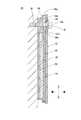
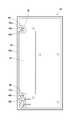
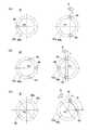
以下、本発明に係るプレート部材の位置決め構造および字光式ナンバープレートの実施形態について、図面を参照しながら説明する。図1は、本発明の一実施形態に係る字光式ナンバープレート10の構成を示す分解斜視図である。図2は、字光式ナンバープレート10の構成を示す断面図である。図3は、字光式ナンバープレート10のケース24の構成を示す正面図である。図4は、ケース24の構成を示す拡大斜視図である。図5は、プレート部材の位置決め構造Wを模式的に示す正面図である。 Hereinafter, the positioning structure of the plate member and the embodiment of the character light type license plate according to the present invention will be described with reference to the drawings. FIG. 1 is an exploded perspective view showing the configuration of a character light
(字光式ナンバープレート10の構成)
図1に示す字光式ナンバープレート10は、車両M(図2)を識別するための文字を表示する標識であり、ナンバープレート12とナンバープレート用照明装置(以下、「照明装置」という。)14とを備えている。図2に示すように、字光式ナンバープレート10は、自動車や自動二輪車などの車両Mに対して、第1ボルト16aおよび第2ボルト16b(図1)を用い取り付けられる。本実施形態では、ナンバープレート12が本発明の「プレート部材」に相当し、照明装置14が本発明の「基体」に相当する。図4に示すプレート部材の位置決め構造Wは、ナンバープレート12の照明装置14に対する位置決め構造であり、字光式ナンバープレート10の一部である。(Structure of character light type license plate 10)
The character light
本実施形態の説明で用いる上、下、左、右、表および裏の各方向は、図1中に矢印で示したこれらの方向と一致する。つまり、上、下、左および右の方向は、字光式ナンバープレート10を車両M(図2)に取り付けたときのこれらの方向と一致し、表および裏の方向は、ナンバープレート12の表裏の方向と一致する。 The upper, lower, left, right, front, and back directions used in the description of the present embodiment coincide with these directions indicated by arrows in FIG. That is, the top, bottom, left and right directions coincide with these directions when the character light
(ナンバープレート12の構成)
図1に示すように、ナンバープレート12は、「運輸支局の地名」、「車両の種別番号」、「車両の用途を示す文字」および「車両の登録番号」のそれぞれを構成する文字を表示する板状のプレート部材あり、金属等からなる遮光性を有する板状の基板18と、合成樹脂等からなる光透過性の文字形成部材20とを有している。(Configuration of license plate 12)
As shown in FIG. 1, the
基板18は、文字の形状に打ち抜かれた複数の貫通孔(図示省略)を有しており、文字形成部材20は、これらの貫通孔を覆うようにして基板18の表面に設けられている。また、基板18の上部の右端部側には、第1ボルト16aが挿通される円形の第1プレート貫通孔22aが形成されており、基板18の上部の左端部側には、第2ボルト16bが挿通される円形の第2プレート貫通孔22bが形成されている。 The
(照明装置14の構成)
図1に示すように、照明装置14は、ケース24、回路基板26、光源28、導光板30および光拡散板32を備えている。図2に示すように、回路基板26、光源28(図1)および導光板30は、ケース24の内部に収容されており、光拡散板32は、ケース24の開口に嵌め込まれている。(Structure of lighting device 14)
As shown in FIG. 1, the
図3に示すように、ケース24は、合成樹脂等からなる遮光性の部材であり、左右方向に長い長方形に形成された板状の底壁部34と、底壁部34の周縁部から表側に立ち上がって形成された周壁部36とを有している。 As shown in FIG. 3, the
図4に示すように、底壁部34の上部の右端部側には、ナンバープレート12の第1プレート貫通孔22aに対応する台状の第1部分38aが形成されている。第1部分38aには、第1ボルト16aが挿入される第1基体貫通孔40aが表裏の方向に延びて形成されている。第1部分38aの表面は、ナンバープレート12を受ける第1プレート支持面42aとなっており、第1基体貫通孔40aの表側の開口が第1プレート支持面42aに開かれている。 As shown in FIG. 4, a trapezoidal
図4に示すように、底壁部34の上部の左端部側には、ナンバープレート12の第2プレート貫通孔22bに対応する台状の第2部分38bが形成されている。第2部分38bには、第2ボルト16bが挿入される第2基体貫通孔40bが表裏の方向に延びて形成されている。第2部分38bの表面は、ナンバープレート12を受ける第2プレート支持面42bとなっており、第2基体貫通孔40bの表側の開口が第2プレート支持面42bに開かれている。 As shown in FIG. 4, a trapezoidal
図4に示すように、第1プレート支持面42aおよび第2プレート支持面42bは、周壁部36の表側の端面36aとほぼ面一となるように形成されている。そして、第1プレート支持面42aおよび第2プレート支持面42bには、プレート部材の位置決め構造Wが構成されている。 As shown in FIG. 4, the first
図4に示すように、プレート部材の位置決め構造Wは、第1プレート貫通孔22aに内接する少なくとも2つの第1突起46と、第2プレート貫通孔22bに内接する少なくとも1つの第2突起48とを備えている。本実施形態では、3つの第1突起46と3つの第2突起48とが、第1部分38aと第2部分38bとの中間に位置する対称軸(図示省略)において線対称に形成されている。 As shown in FIG. 4, the positioning structure W of the plate member includes at least two
第1突起46のそれぞれは、第1プレート貫通孔22aに対応する第1部分38aの表面(すなわち第1プレート支持面42a)に第1プレート貫通孔22aの貫通方向に半球状に突出して設けられている。この場合、第1突起46の突出量は、第1プレート貫通孔22aの孔の深さ以下であればよいが、好ましくは1/2以下、より好ましくは1/3以下である。図5に示すように、第1突起46の全ては、第1プレート貫通孔22aの内周面に沿うように180度未満の角度範囲α(本実施形態では150度の範囲)内に設けられている。 Each of the
したがって、図5に示すように、第1突起46の全てに外接する最小外接円Rの直径D1は、第1プレート貫通孔22aの内径D2よりも小さくなり、第1突起46にのみ着目したときには、第1突起46の全てを第1プレート貫通孔22aの内側に配置した状態でも、第1プレート貫通孔22aを第1突起46に対して移動させることができる。つまり、「プレート部材」としてのナンバープレート12を「基体」としての照明装置14に対して移動させることができる。 Therefore, as shown in FIG. 5, the diameter D1 of the minimum circumscribed circle R circumscribing all of the
図4に示すように、第2突起48のそれぞれは、第2プレート貫通孔22bに対応する第2部分38bの表面(すなわち第2プレート支持面42b)に第2プレート貫通孔22bの貫通方向に半球状に突出して設けられている。この場合、第2突起48の突出量は、第2プレート貫通孔22bの孔の深さ以下であればよいが、好ましくは1/2以下、より好ましくは1/3以下である。 As shown in FIG. 4, each of the
図5に示すように、第1プレート貫通孔22aの貫通方向に対して直交し、かつ、上記の角度範囲α(本実施形態では150度の範囲)の両端に位置する2つの第1突起46を通過する仮想直線Lを想定し、第1プレート貫通孔22aの中心線P1を仮想直線Lまで最短で移動させるときの仮の移動方向Sを想定したとき、第2突起48の全ては、第2プレート貫通孔22bの中心線P2よりも仮の移動方向Sの後方に設けられている。 As shown in FIG. 5, two
図5に示すように、第1突起46の全てを第1プレート貫通孔22aの内側に配置した状態において、第1プレート貫通孔22aは、第1突起46に対して仮の移動方向Sに相対的に移動し易く、その反対の方向には移動できない。第2突起48は、第2プレート貫通孔22bの中心線P2よりも仮の移動方向Sの後方に設けられているので、第1プレート貫通孔22aが第1突起46に対して仮の移動方向Sに移動しようとしたときには、第2プレート貫通孔22bの内面が第2突起48に当接してその移動を阻止する。 As shown in FIG. 5, in a state where all of the
図1に示す回路基板26は、合成樹脂等からなる絶縁性の絶縁基板(図示省略)と、絶縁基板の表面にプリント配線技術により形成された電気配線(図示省略)とを有している。図1に示す光源28は、ナンバープレート12の各文字に照射する光を発生させるものであり、複数の発光部28aを互いに間隔を隔てて配置することによって構成されている。本実施形態の発光部28aは、発光ダイオード(LED)であり、文字の大きさに応じて、発光部28aの数が定められている。 The
図1に示す導光板30は、アクリルやポリカーボネート等の合成樹脂からなる透明な板状の本体部50を有している。本体部50の裏面には、光源28から出た光をナンバープレート12の各文字に導くための導光部52が形成されている。図1に示す光拡散板32は、導光板30からナンバープレート12に向かう光を均一に拡散させるものであり、ポリエチレンやポリプロピレン等の合成樹脂によって、光透過性を有する板状に形成されている。図2に示すように、光拡散板32は、ケース24の開口に嵌め込まれており、ケース24と光拡散板32とが熱溶着等の接合手段(図示省略)で接合されている。 The
(字光式ナンバープレート10の作動)
字光式ナンバープレート10を車両M(図2)に取り付ける際には、図4に示す第1プレート支持面42aおよび第2プレート支持面42bにナンバープレート12の裏面を当接させる。このとき、少なくとも2つ(本実施形態では3つ)の第1突起46の全てを第1プレート貫通孔22aに内接させるとともに、少なくとも1つ(本実施形態では3つ)の第2突起48の全てを第2プレート貫通孔22bに内接させる。(Operation of letter light type license plate 10)
When the character light
その後、ナンバープレート12の第1プレート貫通孔22aおよび照明装置14の第1基体貫通孔40aに表側から第1ボルト16a(図1)を挿通させて、これを車両M(図2)に設けられた雌ねじ(図示省略)に螺合する。また、ナンバープレート12の第2プレート貫通孔22bおよび照明装置14の第2基体貫通孔40bに表側から第2ボルト16b(図1)を挿通させて、これを車両Mに設けられた雌ねじ(図示省略)に螺合する。さらに、光源28(図1)と車両Mに搭載されたバッテリー(図示省略)とを電線を用いて電気的に接続する。 After that, the
車両に設けられたスイッチ(図示省略)を操作して、光源28(図1)に電力を供給すると、光源28が光を発生させる。すると、この光が導光板30の導光部52(図1)によってナンバープレート12(図1)の対応する各文字に導かれ、光拡散板32を介して各文字が裏側から照らされて発光する。 When a switch (not shown) provided in the vehicle is operated to supply electric power to the light source 28 (FIG. 1), the
(字光式ナンバープレート10の効果)
本実施形態によれば、上記構成により以下の各効果を奏することができる。すなわち、少なくとも2つの第1突起46を第1プレート貫通孔22aに内接させ、かつ、少なくとも1つの第2突起48を第2プレート貫通孔22bに内接させることによって、「プレート部材」としてのナンバープレート12(図1)を「基体」としての照明装置14(図1)に対して位置決めすることができる。(Effect of character light type license plate 10)
According to the present embodiment, the following effects can be achieved by the above configuration. That is, by inscribed at least two
図5に示すように、第1突起46の全ては、第1プレート貫通孔22aの内周面に沿って180度未満の角度範囲α内に設けられているので、第1突起46の全てを第1プレート貫通孔22aの内側に配置した状態でも、ナンバープレート12を照明装置14に対して移動させることが可能である。したがって、位置決め作業では、まず、第1突起46の全てを第1プレート貫通孔22aの内側に配置し、その後、ナンバープレート12を照明装置14に対して移動させて第2突起48を第2プレート貫通孔22bの内側に配置することができる。これにより位置決め作業を簡単に行うことができる。 As shown in FIG. 5, since all of the
図5に示すように、第2突起48は、第2プレート貫通孔22bの中心線P2よりも仮の移動方向Sの後方に設けられているので、第1プレート貫通孔22aが第1突起46に対して仮の移動方向Sに移動しようとしたときには、第2プレート貫通孔22bの内面が第2突起48に当接してその移動を阻止する。したがって、ナンバープレート12を照明装置14に対して確実に位置決めすることができる。 As shown in FIG. 5, since the
図5に示すように、第2突起48は、第2プレート貫通孔22bの中心線P2よりも仮の移動方向Sの後方に設けられているので、位置決め作業では、まず、第2突起48の全てを第2プレート貫通孔22bの内側に配置し、その後、ナンバープレート12を照明装置14に対して移動させて第1突起46を第1プレート貫通孔22aの内側に配置することもできる。 As shown in FIG. 5, since the
図4に示すように、作業者は、第1突起46と第2突起48とが線対称に形成されているので、ナンバープレート12を照明装置14に対して位置決めする際には、第1突起46の全てを第1プレート貫通孔22aの内側に配置した後、第2突起48を第2プレート貫通孔22bの内側に配置する場合でも、その逆で第2突起48を第2プレート貫通孔22bの内側に配置した後、第1突起46の全てを第1プレート貫通孔22aの内側に配置した場合でも、ほぼ同じ作業感覚で位置決め作業を行うことができる。また、作業者は、第1突起46と第2特許48とを同時に第1プレート貫通孔22aおよび第2プレート貫通孔22bに配置することもできる。 As shown in FIG. 4, since the
図4に示すように、第1ボルト16aが挿入される第1基体貫通孔40aの周囲に第1突起46が設けられ、第2ボルト16bが挿入される第2基体貫通孔40bの周囲に第2突起48が設けられるので、第1ボルト16aおよび第2ボルト16bを用いてナンバープレート12を照明装置14に接続したときには、第1プレート貫通孔22aおよび第2プレート貫通孔22bと第1突起46および第2突起48との位置決め状態を確実に保持できる。 As shown in FIG. 4, a
図1に示すナンバープレート12の文字の位置が導光板30から照射される光の照射位置に対してずれていると、文字の明るさにむらが生じるおそれがあるが、上記実施形態では、ナンバープレート12を照明装置14に対して正確に位置決めすることができるので、文字の明るさにむらが生じることを抑制できる If the position of the characters on the
(変形例)
なお、本発明の実施にあたっては、上記実施形態に限定されず、本発明の目的を逸脱しない限りにおいて種々の変更が可能である。すなわち、図4に示すように、上記実施形態では、「基体」としての照明装置14の右端部側の第1プレート支持面42a上に第1突起46が形成され、左端部側の第2プレート支持面42b上に第2突起48が形成されているが、これらの位置は逆にされてもよい。つまり、照明装置14の左端部側の第2プレート支持面42b上に第1突起46が形成され、右端部側の第1プレート支持面42a上に第2突起48が形成されてもよい。(Modification example)
The implementation of the present invention is not limited to the above-described embodiment, and various changes can be made as long as the object of the present invention is not deviated. That is, as shown in FIG. 4, in the above embodiment, the
また、上記実施形態では、第1突起46および第2突起48は、それぞれ凸状の半球状に形成した。しかし、第1特許46および第2突起48は、凸状に突出して形成されていればよい。したがって、第1特許46および第2突起48は、平面視で三角形、四角形、五角形または六角形などの多角形状、楕円または異形形状の柱状または錐状に形成することもできる。 Further, in the above embodiment, the
図6は、プレート部材の位置決め構造Wの変形例を模式的に示す正面図であり、図6(A)は第1突起46および第2突起48の数を変更した状態を示す正面図、図6(B)は仮の移動方向Sを反対にした状態を示す正面図、図6(C)は仮の移動方向Sを斜めにした状態を示す正面図である。 FIG. 6 is a front view schematically showing a modified example of the positioning structure W of the plate member, and FIG. 6A is a front view and a view showing a state in which the numbers of the
図4に示すように、上記実施形態では、第1プレート支持面42aに3つの第1突起46が設けられているが、第1突起46の数は少なくとも2つあればよい。したがって、図6(A)に示すように2つでもよいし、図示していないが4つ以上でもよい。ただし、第1突起46の全ては、第1プレート貫通孔22aの内周面に沿って180度未満の小さい角度範囲α内に設けられている必要がある。 As shown in FIG. 4, in the above embodiment, the first
図4に示すように、上記実施形態では、第2プレート支持面42bに3つの第2突起48が設けられているが、第2突起48の数は少なくとも1つあればよい。したがって、図6(A)に示すように1つでもよいし、図示していないが2つでも4つ以上でもよい。ただし、第2突起48の全ては、第2プレート貫通孔22bの中心線P2よりも仮の移動方向Sの後方に設けられている必要がある。 As shown in FIG. 4, in the above embodiment, the second
図5に示すように、上記実施形態では、仮の移動方向Sが、第2プレート貫通孔22bの中心線P2が位置している方向とは反対の方向に向けられているが、仮の移動方向Sは他の方向に向けられてもよい。例えば、図6(B)に示すように、仮の移動方向Sは、第2プレート貫通孔22bの中心線P2が位置している方向に向けられてもよい。また、図6(C)に示すように、第2プレート貫通孔22bの中心線P2が位置している方向に対して傾斜した方向に向けられてもよい。これらの場合でも、第2突起48を第2プレート貫通孔22bの中心線P2よりも仮の移動方向Sの後方に設けることによって、ナンバープレート12を確実に位置決めすることができる。 As shown in FIG. 5, in the above embodiment, the temporary movement direction S is directed in the direction opposite to the direction in which the center line P2 of the second plate through
上記実施形態では、プレート部材の位置決め構造W(図4)を字光式ナンバープレート10に用いた場合を示したが、この構造は、字光式ナンバープレート10の他、板状のプレート部材を基体に対して位置決めする様々な用途に使用できる。例えば、「プレート部材」としての装飾板を「基体」としての機械装置に取り付ける用途などにも使用できる。 In the above embodiment, the case where the positioning structure W (FIG. 4) of the plate member is used for the character light
L…仮想直線、P1… 第1プレート貫通孔の中心線、
P2…第2プレート貫通孔の中心線、R…最小外接円、S…仮の移動方向、
W…プレート部材の位置決め構造、10…字光式ナンバープレート、
12…ナンバープレート、14…ナンバープレート用照明装置、16a…第1ボルト、
16b…第2ボルト、22a…第1プレート貫通孔、22b…第2プレート貫通孔、
38a…第1部分、38b…第2部分、40a…第1基体貫通孔、
40b…第2基体貫通孔、42a…第1プレート支持面、42b…第2プレート支持面、
46…第1突起、48…第2突起。L ... Virtual straight line, P1 ... Center line of the first plate through hole,
P2 ... Center line of the second plate through hole, R ... Minimum circumscribed circle, S ... Temporary movement direction,
W ... Plate member positioning structure, 10 ... Character light type license plate,
12 ... License plate, 14 ... License plate lighting device, 16a ... 1st volt,
16b ... 2nd bolt, 22a ... 1st plate through hole, 22b ... 2nd plate through hole,
38a ... 1st part, 38b ... 2nd part, 40a ... 1st substrate through hole,
40b ... Second substrate through hole, 42a ... First plate support surface, 42b ... Second plate support surface,
46 ... 1st protrusion, 48 ... 2nd protrusion.
Claims (6)
Translated fromJapanese前記基体における前記第1プレート貫通孔に対応する第1部分の表面に前記第1プレート貫通孔の貫通方向に突出して設けられ、前記第1プレート貫通孔に内接する少なくとも2つの第1突起と、
前記基体における前記第2プレート貫通孔に対応する第2部分の表面に前記第2プレート貫通孔の貫通方向に突出して設けられ、前記第2プレート貫通孔に内接する少なくとも1つの第2突起とを備え、
前記第1突起の全ては、前記第1プレート貫通孔の内周面に沿って180度未満の角度範囲内に設けられており、
前記第1プレート貫通孔の貫通方向に対して直交し、かつ、前記角度範囲の両端に位置する2つの第1突起を通過する仮想直線を想定し、前記第1プレート貫通孔の中心線を前記仮想直線まで最短で移動させるときの仮の移動方向を想定したとき、前記第2突起は、前記第2プレート貫通孔の中心線よりも前記仮の移動方向の後方に設けられている、プレート部材の位置決め構造。It is a positioning structure of a plate member that positions a plate-shaped plate member having a first plate through hole and a second plate through hole provided at a distance from each other with respect to a substrate.
At least two first protrusions provided on the surface of the first portion of the substrate corresponding to the first plate through hole so as to project in the penetration direction of the first plate through hole and inscribed in the first plate through hole.
At least one second protrusion, which is provided on the surface of the second portion of the substrate corresponding to the second plate through hole so as to project in the penetration direction of the second plate through hole and is inscribed in the second plate through hole. Prepare,
All of the first protrusions are provided within an angle range of less than 180 degrees along the inner peripheral surface of the first plate through hole.
Assuming a virtual straight line that is orthogonal to the penetration direction of the first plate through hole and passes through two first protrusions located at both ends of the angle range, the center line of the first plate through hole is defined as described above. Assuming a temporary movement direction when moving to a virtual straight line in the shortest time, the second protrusion is provided behind the center line of the second plate through hole in the temporary movement direction. Positioning structure.
前記第2プレート貫通孔に挿通される第2ボルトとをさらに備え、
前記基体の前記第1部分には、前記第1ボルトが挿入される第1基体貫通孔が形成されており、
前記基体の前記第2部分には、前記第2ボルトが挿入される第2基体貫通孔が形成されており、
前記第1突起は、前記第1部分の表面に開かれた前記第1基体貫通孔の開口の周囲に設けられており、
前記第2突起は、前記第2部分の表面に開かれた前記第2基体貫通孔の開口の周囲に設けられている、請求項1ないし3のいずれか1項に記載のプレート部材の位置決め構造。The first bolt inserted into the first plate through hole and
Further provided with a second bolt to be inserted into the second plate through hole,
A first substrate through hole into which the first bolt is inserted is formed in the first portion of the substrate.
A second substrate through hole into which the second bolt is inserted is formed in the second portion of the substrate.
The first protrusion is provided around the opening of the first substrate through hole opened on the surface of the first portion.
The positioning structure for a plate member according to any one of claims 1 to 3, wherein the second protrusion is provided around an opening of the second substrate through hole opened on the surface of the second portion. ..
前記プレート部材は、車両を識別するための文字が表示されたナンバープレートであり、
前記基体は、前記文字に裏側から光を照射するナンバープレート用照明装置である、字光式ナンバープレート。A character light type license plate provided with the positioning structure of the plate member according to claim 4.
The plate member is a license plate on which characters for identifying a vehicle are displayed.
The substrate is a character light type license plate, which is a license plate lighting device that irradiates the characters with light from the back side.
回路基板と、
前記回路基板に設けられた光源と、
前記光源から出た光を前記文字に導く導光板と、
前記回路基板、前記光源および前記導光板を収容するケースとを備え、
前記第1部分および前記第2部分は前記ケースに形成されている、請求項5に記載の字光式ナンバープレート。The license plate lighting device is
With the circuit board
The light source provided on the circuit board and
A light guide plate that guides the light emitted from the light source to the characters,
A case including the circuit board, the light source, and the light guide plate is provided.
The character light type license plate according to claim 5, wherein the first portion and the second portion are formed in the case.
Priority Applications (1)
| Application Number | Priority Date | Filing Date | Title |
|---|---|---|---|
| JP2019134256AJP2021017145A (en) | 2019-07-22 | 2019-07-22 | Positioning structure of plate member and backlit license plate |
Applications Claiming Priority (1)
| Application Number | Priority Date | Filing Date | Title |
|---|---|---|---|
| JP2019134256AJP2021017145A (en) | 2019-07-22 | 2019-07-22 | Positioning structure of plate member and backlit license plate |
Publications (1)
| Publication Number | Publication Date |
|---|---|
| JP2021017145Atrue JP2021017145A (en) | 2021-02-15 |
Family
ID=74563466
Family Applications (1)
| Application Number | Title | Priority Date | Filing Date |
|---|---|---|---|
| JP2019134256APendingJP2021017145A (en) | 2019-07-22 | 2019-07-22 | Positioning structure of plate member and backlit license plate |
Country Status (1)
| Country | Link |
|---|---|
| JP (1) | JP2021017145A (en) |
Cited By (1)
| Publication number | Priority date | Publication date | Assignee | Title |
|---|---|---|---|---|
| JP2025019724A (en)* | 2023-07-28 | 2025-02-07 | 大作 金子 | Number Base |
- 2019
- 2019-07-22JPJP2019134256Apatent/JP2021017145A/enactivePending
Cited By (1)
| Publication number | Priority date | Publication date | Assignee | Title |
|---|---|---|---|---|
| JP2025019724A (en)* | 2023-07-28 | 2025-02-07 | 大作 金子 | Number Base |
Similar Documents
| Publication | Publication Date | Title |
|---|---|---|
| JP4914432B2 (en) | Illumination input device | |
| US10288794B2 (en) | Illumination device of vehicle | |
| JP2017224413A (en) | Light emission emblem | |
| JP4714098B2 (en) | Lighting equipment | |
| JP2016515751A (en) | Key module for keyboard key and method for manufacturing the same | |
| KR20090032116A (en) | Automotive display device comprising substantially parallel light beams | |
| JP2005032703A (en) | Illumination device and illumination input device | |
| JP5337219B2 (en) | Illuminated license plate license plate | |
| JP2021017145A (en) | Positioning structure of plate member and backlit license plate | |
| JP2008021613A (en) | Illumination device | |
| JP2021017144A (en) | Illumination device for license plate | |
| JP7197351B2 (en) | Display device, lighting device, light guide member and light guide structure | |
| KR102445415B1 (en) | Electric device for vehicle scaffolding | |
| CN108980777A (en) | Baffle component for vehicle and the vehicle with baffle component | |
| JP3228095U (en) | Light guide plate and lighting equipment | |
| JP2015102797A (en) | Light-emitting license plate | |
| JP6973273B2 (en) | Lighting equipment for vehicles | |
| JP2020042963A (en) | Luminaire and prism | |
| JP2008174131A (en) | Vehicle interior lighting device | |
| JP2007033346A (en) | Lighting device | |
| JP7249462B1 (en) | lighting equipment | |
| KR101231969B1 (en) | A lighting device for button | |
| JP5103552B1 (en) | Lighting device | |
| JP4011339B2 (en) | Light guide plate for lighting | |
| JP2024103060A (en) | Illuminated number plate lighting equipment |