JP2021016833A - Filtration module, deairing filtration unit and inkjet image formation device - Google Patents
Filtration module, deairing filtration unit and inkjet image formation deviceDownload PDFInfo
- Publication number
- JP2021016833A JP2021016833AJP2019134550AJP2019134550AJP2021016833AJP 2021016833 AJP2021016833 AJP 2021016833AJP 2019134550 AJP2019134550 AJP 2019134550AJP 2019134550 AJP2019134550 AJP 2019134550AJP 2021016833 AJP2021016833 AJP 2021016833A
- Authority
- JP
- Japan
- Prior art keywords
- filter
- mesh
- filtration
- filtration module
- degassing
- Prior art date
- Legal status (The legal status is an assumption and is not a legal conclusion. Google has not performed a legal analysis and makes no representation as to the accuracy of the status listed.)
- Granted
Links
- 238000001914filtrationMethods0.000titleclaimsabstractdescription80
- 230000015572biosynthetic processEffects0.000titledescription2
- 238000007872degassingMethods0.000claimsabstractdescription42
- 239000012530fluidSubstances0.000claimsabstractdescription16
- 238000007789sealingMethods0.000claimsabstractdescription4
- 230000003746surface roughnessEffects0.000claimsdescription12
- 229910052782aluminiumInorganic materials0.000claimsdescription2
- XAGFODPZIPBFFR-UHFFFAOYSA-NaluminiumChemical compound[Al]XAGFODPZIPBFFR-UHFFFAOYSA-N0.000claimsdescription2
- 230000002093peripheral effectEffects0.000abstractdescription16
- 238000004519manufacturing processMethods0.000abstractdescription9
- 238000010586diagramMethods0.000abstractdescription3
- 239000000976inkSubstances0.000description52
- 239000007788liquidSubstances0.000description10
- 239000012510hollow fiberSubstances0.000description9
- 238000010438heat treatmentMethods0.000description5
- 238000011144upstream manufacturingMethods0.000description3
- 238000005452bendingMethods0.000description2
- 238000009530blood pressure measurementMethods0.000description2
- 239000003086colorantSubstances0.000description2
- 238000000034methodMethods0.000description2
- 239000002245particleSubstances0.000description2
- 229910001220stainless steelInorganic materials0.000description2
- 239000010935stainless steelSubstances0.000description2
- 238000003466weldingMethods0.000description2
- 229910001111Fine metalInorganic materials0.000description1
- 239000004744fabricSubstances0.000description1
- 238000009434installationMethods0.000description1
- 230000001678irradiating effectEffects0.000description1
- 238000005259measurementMethods0.000description1
- 229910052751metalInorganic materials0.000description1
- 239000002184metalSubstances0.000description1
- 239000011148porous materialSubstances0.000description1
- 238000007639printingMethods0.000description1
- 239000011347resinSubstances0.000description1
- 229920005989resinPolymers0.000description1
- 239000007779soft materialSubstances0.000description1
- 239000000126substanceSubstances0.000description1
- 238000009941weavingMethods0.000description1
- 238000004804windingMethods0.000description1
- 239000002759woven fabricSubstances0.000description1
Images


Landscapes
- Ink Jet (AREA)
- Filtration Of Liquid (AREA)
Abstract
Translated fromJapaneseDescription
Translated fromJapanese本発明は、濾過モジュール、脱気濾過ユニットおよびインクジェット画像形成装置に関する。 The present invention relates to a filtration module, a degassing filtration unit and an inkjet image forming apparatus.
インクジェット装置画像形成においては、インクを流す流路内にフィルターが設けられており、このフィルターによりインク内の異物を捕集している。 In the image formation of an inkjet device, a filter is provided in a flow path through which ink flows, and the filter collects foreign substances in the ink.
例えば、特許文献1には、金属メッシュのフィルターと、フィルターの保持部材と、フィルター及び保持部材の外周を取り囲むフィルターケースと、Oリングとを備えた構成が開示されている。この特許文献1では、Oリングは、流路ブロックとフィルターケース間の密閉性を与えると共に、保持部材とフィルターを保持する役割がある。 For example,
しかしながら、特許文献1に記載された技術では、Oリングはフィルターを保持する役割であり、フィルター周端(Oリングとフィルターとの間の隙間やフィルターとフィルターケースとの間の隙間)からインク内の異物がすり抜けるおそれがある。 However, in the technique described in
そこで、フィルター自身の外周部分に溶着などにより環状のフランジ部を設け、このフランジ部をOリングで押圧すれば、フィルター周端からの異物のすり抜けを防止することはできる。しかしながら、フィルターにフランジ部を設けるための製造コストがかかるという問題がある。 Therefore, if an annular flange portion is provided on the outer peripheral portion of the filter itself by welding or the like and the flange portion is pressed by an O-ring, it is possible to prevent foreign matter from slipping through from the peripheral end of the filter. However, there is a problem that the manufacturing cost for providing the flange portion on the filter is high.
本発明の目的は、製造コストを抑えると共に、フィルター周端からの異物のすり抜けを防止する濾過モジュール、脱気濾過ユニットおよびインクジェット画像形成装置を提供することにある。 An object of the present invention is to provide a filtration module, a degassing filtration unit, and an inkjet image forming apparatus, which suppress the manufacturing cost and prevent foreign matter from slipping through from the peripheral end of the filter.
本発明に係る濾過モジュールは、
流体の濾過を行う濾過モジュールであって、
メッシュから形成されたフィルターと、
メッシュの表面との間の隙間が、メッシュの穴の大きさ以下となるように、メッシュの面上に押圧されるシール部材と、
を備える。The filtration module according to the present invention
A filtration module that filters fluids
With a filter formed from a mesh,
A sealing member pressed onto the surface of the mesh so that the gap between the surface of the mesh is less than or equal to the size of the hole in the mesh.
To be equipped.
また、本発明に係る脱気濾過ユニットは、
流体の脱気を行う脱気モジュールと、
流体の流れ方向における脱気モジュールの下流側に設けられ、脱気後の流体の濾過を行う、上記の濾過モジュールと、
を備える。Further, the degassing filtration unit according to the present invention is
A degassing module that degass the fluid and
The above-mentioned filtration module, which is provided on the downstream side of the degassing module in the fluid flow direction and filters the fluid after degassing,
To be equipped.
さらに、本発明に係るインクジェット画像形成装置は、
上記の脱気濾過ユニットと、
流体の流れ方向における脱気濾過ユニットの下流側に設けられ、流体としてのインクを吐出するインクジェットヘッドと、
を備える。Further, the inkjet image forming apparatus according to the present invention is
With the above degassing filtration unit,
An inkjet head provided on the downstream side of the degassing filtration unit in the fluid flow direction and ejecting ink as a fluid,
To be equipped.
本発明によれば、製造コストを抑えると共に、フィルター周端からの異物のすり抜けを防止することができる。 According to the present invention, it is possible to suppress the manufacturing cost and prevent foreign matter from slipping through from the peripheral end of the filter.
以下、本発明の実施の形態に係る濾過モジュール、脱気濾過ユニットおよびインクジェット画像形成装置を図面に基づいて詳細に説明する。 Hereinafter, the filtration module, the degassing filtration unit, and the inkjet image forming apparatus according to the embodiment of the present invention will be described in detail with reference to the drawings.
(インクジェット画像形成装置)
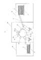
図1は、インクジェット画像形成装置1の概略構成を示す図である。インクジェット画像形成装置1は、給紙部10と、画像形成部20と、排紙部30と、メインタンク40(図2参照)と、制御部(図示省略)とを備える。(Inkjet image forming device)
FIG. 1 is a diagram showing a schematic configuration of an inkjet
インクジェット画像形成装置1は、制御部による制御下で、給紙部10に格納された記録媒体Pを画像形成部20に搬送し、画像形成部20で記録媒体Pに画像を形成し、画像が形成された記録媒体Pを排紙部30に搬送する。記録媒体Pとしては、普通紙や塗工紙といった紙のほか、布帛またはシート状の樹脂など、表面に着弾したインクを定着させることが可能な種々の媒体を用いることができる。 Under the control of the control unit, the inkjet
給紙部10は、記録媒体Pを格納する給紙トレイ11と、給紙トレイ11から画像形成部20に記録媒体Pを搬送して供給する媒体供給部12とを有する。媒体供給部12は、内側が2本のローラーにより支持された輪状のベルトを備え、このベルト上に記録媒体Pを載置した状態でローラーを回転させることで記録媒体Pを給紙トレイ11から画像形成部20へ搬送する。 The
画像形成部20は、搬送部21と、受け渡しユニット22と、加熱部23と、ヘッドユニット50と、定着部24と、デリバリー部25となどを有する。 The
搬送部21は、円筒状の搬送ドラム211の搬送面212(載置面)の上に載置された記録媒体Pを保持し、搬送ドラム211がその回転軸(円筒軸)を中心に矢印方向に回転して周回移動することで当該搬送ドラム211上の記録媒体Pを搬送する搬送動作を行う。 The
受け渡しユニット22は、給紙部10の媒体供給部12により搬送された記録媒体Pを搬送部21に引き渡す。受け渡しユニット22は、給紙部10の媒体供給部12と搬送部21との間の位置に設けられ、媒体供給部12から搬送された記録媒体Pの一端をスイングアーム部221で保持して取り上げ、受け渡しドラム222を介して搬送部21に引き渡す。 The
加熱部23は、受け渡しドラム222の配置位置とヘッドユニット50の配置位置との間に設けられ、搬送部21により搬送される記録媒体Pが所定の温度範囲内の温度となるように当該記録媒体Pを加熱する。加熱部23は、例えば、赤外線ヒーターなどを有し、制御部から供給される制御信号に基づいて赤外線ヒーターに通電して当該赤外線ヒーターを発熱させる。 The
ヘッドユニット50は、記録媒体Pが保持された搬送ドラム211の回転に応じた適切なタイミングで、搬送ドラム211の搬送面212に対向するインク吐出面(後述のヘッドチップ95)に設けられたノズルからインクを吐出して記録媒体Pに画像を形成する。ヘッドユニット50は、インク吐出面と搬送面212とが所定の距離だけ離隔されるように配置される。画像形成部20では、イエロー(Y)、マゼンタ(M)、シアン(C)、ブラック(K)の4色のインクにそれぞれ対応する4つのヘッドユニット50が記録媒体Pの搬送方向上流側からY,M,C,Kの色の順に所定の間隔で並ぶように配列されている。ヘッドユニット50の構成については、図2を参照して、後述する。 The
定着部24は、搬送部21の幅(搬送ドラム211の回転軸方向の幅)に亘って配置された発光部を有し、搬送部21に載置された記録媒体Pに対して当該発光部から紫外線などのエネルギー線を照射して記録媒体P上に吐出されたインクを硬化させて定着させる。定着部24の発光部は、搬送方向についてヘッドユニット50の配置位置からデリバリー部25の受け渡しドラム251の配置位置までの間において搬送面212と対向して配置される。 The
デリバリー部25は、内側が2本のローラーにより支持された輪状のベルトを有するベルトループ252と、記録媒体Pを搬送部21からベルトループ252に受け渡す円筒状の受け渡しドラム251とを有する。受け渡しドラム251により搬送部21からベルトループ252上に受け渡された記録媒体Pをベルトループ252により搬送して排紙部30に送出する。 The
排紙部30は、デリバリー部25により画像形成部20から送り出された記録媒体Pが載置される板状の排紙トレイ31を有する。 The
(ヘッドユニット)
図2は、インクジェット画像形成装置1が搭載するヘッドユニット50を概略的に示す図である。この図2では、1色のインクに対するヘッドユニット50と共に、対応するメインタンク40を図示している。メインタンク40及びヘッドユニット50については、他の色に対しても同じ構成である。(Head unit)
FIG. 2 is a diagram schematically showing a
メインタンク40は、印刷に用いるインク(流体)を貯蔵している。メインタンク40に貯蔵されたインクは、供給ポンプ41を用いて、サブタンクモジュール60へ供給される。 The
ヘッドユニット50は、サブタンクモジュール60と、脱気モジュール70と、濾過モジュール80と、インクジェットヘッド90となどを備える。サブタンクモジュール60の一方の端部に、脱気モジュール70と濾過モジュール80からなる脱気濾過ユニットが配置されており、濾過モジュール80はサブタンクモジュール60と脱気モジュール70との間に配置されている。このように、脱気モジュール70及び濾過モジュール80を、サブタンクモジュール60の一方の端部に配置しているので、脱気モジュール70や濾過モジュール80を交換する際には、容易に取り外し可能となっている。 The
なお、UVインクなどの熱溶融性インクのように、インクの種類によっては、インクを加熱する場合があるため、その場合には、脱気モジュール70と濾過モジュール80との筐体が互いに熱的に接続された構成であることが望ましい。例えば、これらの筐体が熱伝導率の良いアルミニウムから形成された構成が望ましい。 Note that the ink may be heated depending on the type of ink, such as heat-meltable ink such as UV ink. In that case, the housings of the
サブタンクモジュール60は、第1サブタンク61と、送液ポンプ62と、第2サブタンク63と、液面センサー64と、圧力センサー65となどを備える。供給ポンプ41を用いて、メインタンク40から供給されたインクは、第1サブタンク61に貯蔵される。この第1サブタンク61には、後述するように、インクジェットヘッド90から戻されたインクも貯蔵される。 The
第1サブタンク61に貯蔵されたインクは、送液ポンプ62を用いて吸引することで、脱気モジュール70、濾過モジュール80に送液される。 The ink stored in the
脱気モジュール70へ供給されたインクは、脱気モジュール70で気体(空気)が脱気される。脱気モジュール70は、多数の中空糸からなる中空糸織物を巻き付けて構成された中空糸体71と、中空糸体71にインクを供給する流路パイプ72と、中空糸体71及び流路パイプ72を収容するハウジング73(筐体)とを有している。中空糸体71の中空糸の内部は、図示省略した真空ポンプにより真空状態となっており、中空糸の外面に接触するインクから気体を中空糸の内部に吸引することで、インクの脱気を行っている。なお、この脱気モジュール70は、一例であり、インクの脱気を行うことができれば、どのような構成でも適用可能である。また、インクを加熱する場合には、熱容量の大きい脱気モジュール70に加熱を行うための加熱機構を設ければ良い。 The ink supplied to the
濾過モジュール80へ供給されたインクは、濾過モジュール80でインクが濾過される。この濾過モジュール80は、後述するフィルター84が、脱気モジュール70の流路パイプ72の軸方向と平行又は略平行となるように配置されている。このような配置とすることにより、サブタンクモジュール60の一方の端部に、脱気モジュール70及び濾過モジュール80をコンパクトにして配置することができる。濾過モジュール80の詳細な構成については、図3〜図10を参照して、後述する。 The ink supplied to the
脱気モジュール70で脱気され、濾過モジュール80で濾過されたインクは、送液ポンプ62を用いて、第2サブタンク63に供給される。第2サブタンク63は、図示省略した背圧ポンプにより第2サブタンク63内の空気圧を調整可能な構成となっており、この空気圧の調整により、後述するインクジェットヘッド90のノズルからのインクの吐出を制御している。 The ink degassed by the
第2サブタンク63の内部には、液面センサー64が設けられており、第2サブタンク63に供給されたインクの液面の高さを検出している。濾過モジュール80で異物が捕集されて、濾過モジュール80での圧力損失が大きくなると、濾過モジュール80の交換が必要となる。この液面センサー64では、単位時間あたりの液面の変化率を監視しており、この変化率が所定値より小さくなると、濾過モジュール80の交換をするよう、例えば、アラームなどをインクジェット画像形成装置1で表示するようにしている。 A
また、第2サブタンク63の出口側には、圧力センサー65が設けられており、第2サブタンク63から供給されるインクの吐出圧を検出している。この圧力センサー65は、第2サブタンク63内の空気圧の調整のために使用されている。 A
インクジェットヘッド90は、インレット91と、ヘッド上部流路92と、フィルター93と、ヘッド下部流路94と、ヘッドチップ95と、アウトレット96と、駆動回路(図示省略)となどを備える。なお、図2では、2つのインクジェットヘッド90を直列に接続した構成を例示しているが、インクジェットヘッド90は、1つでも良いし、また、3つ以上を直列に接続した構成でも良い。 The
インレット91はヘッド上部流路92に接続されており、第2サブタンク63からのインクは、インレット91(図2では、上流側のインクジェットヘッド90のインレット91)を介して、ヘッド上部流路92へ供給される。ヘッド上部流路92とヘッド下部流路94との間にはフィルター93が配置されており、ヘッド上部流路92へ供給されたインクは、フィルター93で濾過されて、ヘッド下部流路94へ供給される。 The
ヘッドチップ95には、複数のノズルや個々のノズルの開閉を制御する素子が設けられており、これらの素子が駆動回路により制御される。ヘッド下部流路94へ供給されたインクは、開状態に制御されたノズルから吐出されて画像を形成することになる。 The
アウトレット96もヘッド上部流路92に接続されており、使用(吐出)されなかったインクは、アウトレット96(図2では、下流側のインクジェットヘッド90のアウトレット96)を介して、ヘッド上部流路92から第1サブタンク61へ戻される。なお、ヘッド下部流路94にもアウトレットを別途接続して、使用(吐出)されなかったインクを、ヘッド下部流路94から第1サブタンク61へ戻すようにしても良い。このように、ヘッドユニット50内のインクは循環されており、循環しながら、インク内の異物を濾過モジュール80で濾過することになる。 The
(濾過モジュール)
上述したヘッドユニット50では、脱気モジュール70で脱気されたインクの一部が凝集し、凝集物となるおそれがある。そのため、脱気モジュール70の下流側に濾過モジュール80を設け、異物となった凝集物を含めて、インク内の異物を濾過モジュール80で捕集して、インクの濾過を行うようにしている。(Filtration module)
In the
しかしながら、濾過モジュールとして、特許文献1に記載された技術を適用する場合、特許文献1に記載のOリングはフィルターを保持する役割である。そのため、フィルター周端(Oリングとフィルターとの間の隙間やフィルターとフィルターケースとの間の隙間)からインク内の異物がすり抜けるおそれがある。 However, when the technique described in
また、フィルター自身の外周部分に溶着などにより環状のフランジ部を設け、このフランジ部をOリングで押圧すれば、フィルター周端からの異物のすり抜けを防止することはできるが、フィルターにフランジ部を設けるための製造コストがかかるという問題がある。 Further, if an annular flange portion is provided on the outer peripheral portion of the filter itself by welding or the like and the flange portion is pressed by an O-ring, it is possible to prevent foreign matter from slipping through from the peripheral end of the filter, but the flange portion is attached to the filter. There is a problem that the manufacturing cost for the installation is high.
そこで、本実施の形態では、濾過モジュール80が図3に示す構成を備えている。具体的には、濾過モジュール80が、メッシュから形成されたフィルター84と、Oリング837とメッシュ表面との間の隙間Gがメッシュの穴の大きさ以下となるようにメッシュ表面上に押圧されるシール部材としてのOリング837とを備えている。メッシュの穴の大きさとしては、例えば、メッシュの穴径やメッシュの濾過粒度などが該当する。 Therefore, in the present embodiment, the
フィルター84としては、メッシュから形成されたものであれば、どのようなものでも良い。全面がメッシュで形成されていても良い。また、目的とする濾過粒度に応じて、綾織、平畳織のメッシュなどを用いても良い。いずれのメッシュを用いる場合でも、Oリング837がメッシュ表面上に押圧されたとき、Oリング837とメッシュ表面との間の隙間Gがメッシュの穴の大きさ以下となれば良い。また、シール部材としては、OリングやOリングと同等のもので良いが、メッシュ表面の粗さ(凹凸)に追従して弾性変形する柔らかい素材が望ましい。 The
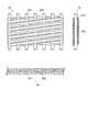
フィルター84の一例として、図3及び図4では、綾畳織のメッシュから形成されるフィルター84を例示している。図3及び図4に示すフィルター84は、例えば、SUS(ステンレススチール)などから形成された金属細線の縦糸841と横糸842とを綾畳織りすることにより形成されている。 As an example of the
本発明者は、メッシュ穴の大きさ10μmの綾畳織のメッシュからなるフィルター84を用いて、後述する構成の濾過モジュール80を試作した。試作前のフィルター84のメッシュ表面の表面粗さ(最大高さ粗さRz)は、測定の結果、15μmであった。試作した濾過モジュール80をバブルポイント圧測定で評価を行った結果、バブルポイント圧測定で得られた気泡の最大孔径が10μm以下であることを確認できた。つまり、図3における隙間Gを含むフィルター84のメッシュ穴の大きさが10μm以下であることを確認できた。これは、フィルター84周端であるOリング837の周囲からも、10μmより大きい異物のすり抜けを防止できることを意味する。 The present inventor has prototyped a
このように、Oリング837とフィルター84のメッシュ表面との間の隙間Gがメッシュの穴の大きさ以下となるようにすることで、フィルター84周端からの異物のすり抜けを防止することができる。また、フィルター84にフランジを設ける必要はないので、製造コストを抑えることもできる。 In this way, by making the gap G between the O-
加えて、図3で説明した構成のフィルター84及びOリング837は、どのような形状のフィルターにも適用可能であるので、フィルター84の形状のデザインの自由度が増すことになる。つまり、どのような形状のフィルターであっても、製造コストを抑えると共に、フィルター周端からの異物のすり抜けを防止することができる。 In addition, since the
次に、上述したフィルター84及びOリング837を備える濾過モジュール80の構成について、図5〜図10を参照して、更に詳細に説明する。 Next, the configuration of the
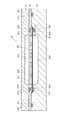
濾過モジュール80は、第1筐体部材81、支持部材82、第2筐体部材83を有する。支持部材82は、第1筐体部材81と第2筐体部材83の間に挟まれている。各部材間は、複数のネジ及びネジ穴を用いて、互いに固定されているが、図5〜図10においては、それらの記載は省略している。 The
第1筐体部材81のサブタンクモジュール60(図2参照)と接する外面側には、インクが排出される排出口811が設けられている。排出口811はサブタンクモジュール60の送液ポンプ62と接続されている。排出口811の周囲にOリング溝812が設けられ、Oリング溝812にOリング813が配置されて、サブタンクモジュール60と第1筐体部材81との間(送液ポンプ62への流路)をシールしている。また、第1筐体部材81の内面側には、図8に示すフィルター84の形状に対応した形状の凹部814(図9参照)が設けられており、排出口811と連通している。 An
支持部材82には、この支持部材82を貫通する複数の開口部821が形成されている。これらの開口部821は、図8に示すフィルター84がある範囲内に配置されており、フィルター84を通過したインクを、第1筐体部材81の凹部814へ通過させている。開口部821同士の間には支持部822が形成されており、複数の支持部822により、濾過モジュール80を流れるインクの下流側からフィルター84を支持して、フィルター84のたわみを防止している。また、これらの開口部821の周囲にOリング溝823が設けられ、Oリング溝823にOリング824が配置されており、第1筐体部材81と支持部材82との間をシールしている。 The
支持部材82に形成する開口部821は、どのような形状でも良いが、フィルター84のたわみを防止しながら開口率を大きくしたい(圧力損失を低減したい)場合には、図6に示すように、長穴形状が望ましい。長穴形状の場合には、加工の製造コストも低く、リブとなる支持部822の強度も確保できる。 The
第2筐体部材83の内面側には、フィルター84に押圧されるOリング837より外周側に、Oリング溝831が設けられ、Oリング溝831にOリング832が配置されており、支持部材82と第2筐体部材83との間をシールしている。 On the inner surface side of the
第2筐体部材83の脱気モジュール70(図2参照)と接する外面側には、インクが供給される供給口833が設けられている。図示は省略しているが、供給口833の周囲にOリング溝が設けられ、このOリング溝にOリングが配置されて、第2筐体部材83と脱気モジュール70との間(脱気モジュール70から濾過モジュール80への流路)をシールしている。 A
第2筐体部材83の内面側にも、フィルター84の形状に対応した形状の凹部834が設けられており、供給口833と連通している。この凹部834には、供給口833から供給されたインクが凹部834の全域に拡がるように、案内溝835が形成されている。 A
凹部834の周縁部にOリング溝836が設けられ、Oリング溝836にOリング837が配置されている。Oリング837は、フィルター84よりも上流側に配置されることになる。このOリング837は、図3で説明したように、フィルター84のメッシュ表面とOリング837との間の隙間Gがメッシュの穴の大きさ以下となるように、メッシュ表面上に押圧されている。これにより、フィルター84周端からの異物のすり抜けを防止できる。なお、インク自体は、フィルター84周端から漏れるが、フィルター84の外側は、上述したOリング832でシールしているので、濾過モジュール80の外側にインクが漏れることはない。 An O-
また、Oリング溝836の内側には、凸部838がOリング溝836に沿って環状に形成されており、その外側には、凸部839がOリング溝836に沿って環状に形成されている。これらの凸部838、839においては、図10に示すように、凸部838の表面とフィルター84のメッシュ表面との隙間H1を、凸部839の表面とフィルター84のメッシュ表面との隙間H2より大きくしている。 Further, on the inside of the O-
Oリング837より外側のフィルター84は、もし、この部分を傷つけても、濾過モジュール80の濾過性能に影響はない。一方、Oリング837より内側のフィルター84が、例えば、凸部838と接触し、この部分を傷つけた場合には、濾過性能が悪化する(阻止すべき大きさの異物がすり抜ける)可能性がある。そのため、上述したように、隙間H1を隙間H2より大きくして、フィルター84が凸部838により傷つかないようにしている。この隙間H1は、Oリング溝836内にOリング837を保持できれば、更に大きくしても良い。 The
また、支持部材82の表面粗さを、フィルター84のメッシュ表面の表面粗さより小さくしている。これは、支持部材82の表面粗さがフィルター84のメッシュ表面の表面粗さより大きい場合には、支持部材82と接するフィルター84のメッシュ表面の表面粗さが、支持部材82の表面粗さに倣って大きくなる可能性があるためである。その場合には、特に、フィルター84のメッシュ表面とOリング837との間の隙間Gに影響する可能性がある。そのため、支持部材82の表面粗さを、フィルター84のメッシュ表面の表面粗さより小さくすることで、上記隙間Gへ影響しないようにしている。支持部材82の表面粗さとしては、その最大高さ粗さRzが、例えば、6.3μm以下であることが望ましい。 Further, the surface roughness of the
上述した構成を有する濾過モジュール80でのインクの流れを簡単に説明する。脱気モジュール70からのインクは、供給口833から供給され、案内溝835を流れて、凹部834の全域に供給される。凹部834に供給されたインクは、フィルター84で濾過され、開口部821を経由して、凹部814へ供給される。凹部814に供給されたインクは、排出口811から排出され、第2サブタンク63に供給される。この際、濾過モジュール80は、図3で説明した構成のフィルター84及びOリング837を有しているので、異物をOリング837の外側に通過させることはなく、当然、凹部834側から凹部814へ通過させることもない。 The flow of ink in the
なお、上記実施の形態では、図3で説明した構成のフィルター84及びOリング837を、ヘッドユニット50の濾過モジュール80に適用した例を説明したが、ヘッドユニット50のインクジェットヘッド90のフィルター93の部分に適用しても良い。更には、濾過が必要な装置であれば、インクジェット画像形成装置1に限らず、他の装置への適用も可能である。 In the above embodiment, an example in which the
また、上記実施の形態では、何れも本発明を実施するにあたっての具体化の一例を示したものに過ぎず、これらによって本発明の技術的範囲が限定的に解釈されてはならないものである。すなわち、本発明はその要旨、またはその主要な特徴から逸脱することなく、様々な形で実施することができる。 Further, in the above-described embodiments, all of them are merely examples of embodiment of the present invention, and the technical scope of the present invention should not be construed in a limited manner by these. That is, the present invention can be implemented in various forms without departing from its gist or its main features.
1 インクジェット画像形成装置
70 脱気モジュール
80 濾過モジュール
81 第1筐体部材
82 支持部材
821 開口部
83 第2筐体部材
838、839 凸部
84 フィルター
837 Oリング1 Inkjet
Claims (11)
Translated fromJapaneseメッシュから形成されたフィルターと、
前記メッシュの表面との間の隙間が、前記メッシュの穴の大きさ以下となるように、前記メッシュの面上に押圧されるシール部材と、
を備える濾過モジュール。A filtration module that filters fluids
With a filter formed from a mesh,
A sealing member pressed onto the surface of the mesh so that the gap between the mesh and the surface is equal to or less than the size of the hole in the mesh.
Filtration module with.
請求項1に記載の濾過モジュール。A support member that supports the filter from the downstream side in the flow direction of the fluid is provided.
The filtration module according to claim 1.
請求項2に記載の濾過モジュール。The surface roughness of the support member is smaller than the surface roughness of the mesh.
The filtration module according to claim 2.
請求項2または3に記載の濾過モジュール。A plurality of openings are formed in the support member.
The filtration module according to claim 2 or 3.
請求項4に記載の濾過モジュール。The opening is an elongated hole,
The filtration module according to claim 4.
前記溝より内側の前記筐体部材の表面と前記メッシュの表面との隙間は、前記溝より外側の前記筐体部材の表面と前記メッシュの表面との隙間より大きい、
請求項1から5のいずれか一項に記載の濾過モジュール。It has a housing member having a groove for arranging the seal member.
The gap between the surface of the housing member inside the groove and the surface of the mesh is larger than the gap between the surface of the housing member outside the groove and the surface of the mesh.
The filtration module according to any one of claims 1 to 5.
請求項1から6のいずれか一項に記載の濾過モジュール。The filtration module according to any one of claims 1 to 6, wherein the filter is formed of a twill tatami mat.
前記流体の流れ方向における前記脱気モジュールの下流側に設けられ、脱気後の前記流体の濾過を行う、請求項1から7のいずれか一項に記載の濾過モジュールと、
を備える脱気濾過ユニット。A degassing module that degass the fluid and
The filtration module according to any one of claims 1 to 7, which is provided on the downstream side of the degassing module in the flow direction of the fluid and filters the fluid after degassing.
Degassing filtration unit equipped with.
請求項8に記載の脱気濾過ユニット。The housing of the filtration module and the housing of the degassing module are thermally connected to each other.
The degassing filtration unit according to claim 8.
請求項9に記載の脱気濾過ユニット。At least one of the housings is made of aluminum,
The degassing filtration unit according to claim 9.
前記流体の流れ方向における前記脱気濾過ユニットの下流側に設けられ、前記流体としてのインクを吐出するインクジェットヘッドと、
を備えるインクジェット画像形成装置。The degassing filtration unit according to any one of claims 8 to 10.
An inkjet head provided on the downstream side of the degassing filtration unit in the flow direction of the fluid and ejecting ink as the fluid, and
An inkjet image forming apparatus comprising.
Priority Applications (1)
| Application Number | Priority Date | Filing Date | Title |
|---|---|---|---|
| JP2019134550AJP7388026B2 (en) | 2019-07-22 | 2019-07-22 | Filtration module, degassing filtration unit and inkjet image forming device |
Applications Claiming Priority (1)
| Application Number | Priority Date | Filing Date | Title |
|---|---|---|---|
| JP2019134550AJP7388026B2 (en) | 2019-07-22 | 2019-07-22 | Filtration module, degassing filtration unit and inkjet image forming device |
Publications (2)
| Publication Number | Publication Date |
|---|---|
| JP2021016833Atrue JP2021016833A (en) | 2021-02-15 |
| JP7388026B2 JP7388026B2 (en) | 2023-11-29 |
Family
ID=74563363
Family Applications (1)
| Application Number | Title | Priority Date | Filing Date |
|---|---|---|---|
| JP2019134550AActiveJP7388026B2 (en) | 2019-07-22 | 2019-07-22 | Filtration module, degassing filtration unit and inkjet image forming device |
Country Status (1)
| Country | Link |
|---|---|
| JP (1) | JP7388026B2 (en) |
Citations (7)
| Publication number | Priority date | Publication date | Assignee | Title |
|---|---|---|---|---|
| JP2002067342A (en)* | 2000-08-30 | 2002-03-05 | Brother Ind Ltd | Fluid supply device, ink jet recording head, and method of manufacturing the same |
| JP2005246212A (en)* | 2004-03-03 | 2005-09-15 | Taiyo Ink Mfg Ltd | Filtering method and production method of paste for electronic material using the method |
| JP2007136871A (en)* | 2005-11-18 | 2007-06-07 | Ricoh Co Ltd | Image forming apparatus |
| JP2011073412A (en)* | 2009-10-02 | 2011-04-14 | Hitachi Industrial Equipment Systems Co Ltd | Inkjet recorder |
| US20150246299A1 (en)* | 2013-09-23 | 2015-09-03 | Halliburton Energy Services, Inc. | Threaded safety cap |
| WO2015190201A1 (en)* | 2014-06-12 | 2015-12-17 | コニカミノルタ株式会社 | Inkjet printing apparatus |
| JP2016182725A (en)* | 2015-03-26 | 2016-10-20 | セイコーエプソン株式会社 | Printer and method for heating ink in printer |
- 2019
- 2019-07-22JPJP2019134550Apatent/JP7388026B2/enactiveActive
Patent Citations (7)
| Publication number | Priority date | Publication date | Assignee | Title |
|---|---|---|---|---|
| JP2002067342A (en)* | 2000-08-30 | 2002-03-05 | Brother Ind Ltd | Fluid supply device, ink jet recording head, and method of manufacturing the same |
| JP2005246212A (en)* | 2004-03-03 | 2005-09-15 | Taiyo Ink Mfg Ltd | Filtering method and production method of paste for electronic material using the method |
| JP2007136871A (en)* | 2005-11-18 | 2007-06-07 | Ricoh Co Ltd | Image forming apparatus |
| JP2011073412A (en)* | 2009-10-02 | 2011-04-14 | Hitachi Industrial Equipment Systems Co Ltd | Inkjet recorder |
| US20150246299A1 (en)* | 2013-09-23 | 2015-09-03 | Halliburton Energy Services, Inc. | Threaded safety cap |
| WO2015190201A1 (en)* | 2014-06-12 | 2015-12-17 | コニカミノルタ株式会社 | Inkjet printing apparatus |
| JP2016182725A (en)* | 2015-03-26 | 2016-10-20 | セイコーエプソン株式会社 | Printer and method for heating ink in printer |
Also Published As
| Publication number | Publication date |
|---|---|
| JP7388026B2 (en) | 2023-11-29 |
Similar Documents
| Publication | Publication Date | Title |
|---|---|---|
| JP2018099858A (en) | Liquid circulation module and liquid discharge device | |
| US7380927B2 (en) | Ink jet recording apparatus | |
| JP6361727B2 (en) | Inkjet recording device | |
| EP3156236B1 (en) | Inkjet printing apparatus | |
| JP2015066842A (en) | Pressure buffer device, liquid circulation device, image recording device, and liquid flow device state detection method | |
| US10875317B2 (en) | Liquid tank, liquid circulation device, and liquid discharge apparatus | |
| JP7102822B2 (en) | Inkjet image forming equipment | |
| JP6870221B2 (en) | Inkjet recording device and abnormality detection method for inkjet recording device | |
| JPWO2017094518A1 (en) | Inkjet recording device | |
| JP2012187862A (en) | Inkjet printer and method of cleaning the same | |
| JP2017154298A (en) | Liquid circulation device and liquid discharge device | |
| JP2016060180A (en) | Ink jet printer | |
| JP2015044344A (en) | Ink supply apparatus, ink supply method, and ink jet recording apparatus | |
| US20170225482A1 (en) | Filter unit and liquid ejecting apparatus | |
| JPWO2017094515A1 (en) | Inkjet recording device | |
| JP2020151941A (en) | Liquid discharge head, head module, head unit, liquid discharge unit, device that discharges liquid | |
| JPWO2017099008A1 (en) | Ink jet recording apparatus and bubble removing method | |
| JP2021016833A (en) | Filtration module, deairing filtration unit and inkjet image formation device | |
| CN113829757B (en) | Ink system of industrial printer | |
| EP3075544B1 (en) | Printing apparatus | |
| US8240832B2 (en) | Head unit and printer | |
| JP6900711B2 (en) | Inkjet recording device and control method of inkjet recording device | |
| JP6613093B2 (en) | Inkjet recording device | |
| JP2018122483A (en) | Liquid discharge device and liquid discharge head | |
| JP2017114091A (en) | Inkjet recording device |
Legal Events
| Date | Code | Title | Description |
|---|---|---|---|
| A621 | Written request for application examination | Free format text:JAPANESE INTERMEDIATE CODE: A621 Effective date:20220621 | |
| A977 | Report on retrieval | Free format text:JAPANESE INTERMEDIATE CODE: A971007 Effective date:20230224 | |
| A131 | Notification of reasons for refusal | Free format text:JAPANESE INTERMEDIATE CODE: A131 Effective date:20230307 | |
| A601 | Written request for extension of time | Free format text:JAPANESE INTERMEDIATE CODE: A601 Effective date:20230508 | |
| A521 | Request for written amendment filed | Free format text:JAPANESE INTERMEDIATE CODE: A523 Effective date:20230704 | |
| TRDD | Decision of grant or rejection written | ||
| A01 | Written decision to grant a patent or to grant a registration (utility model) | Free format text:JAPANESE INTERMEDIATE CODE: A01 Effective date:20231017 | |
| A61 | First payment of annual fees (during grant procedure) | Free format text:JAPANESE INTERMEDIATE CODE: A61 Effective date:20231030 | |
| R150 | Certificate of patent or registration of utility model | Ref document number:7388026 Country of ref document:JP Free format text:JAPANESE INTERMEDIATE CODE: R150 |