JP2021005609A - Printed wiring board and manufacturing method thereof - Google Patents
Printed wiring board and manufacturing method thereofDownload PDFInfo
- Publication number
- JP2021005609A JP2021005609AJP2019118255AJP2019118255AJP2021005609AJP 2021005609 AJP2021005609 AJP 2021005609AJP 2019118255 AJP2019118255 AJP 2019118255AJP 2019118255 AJP2019118255 AJP 2019118255AJP 2021005609 AJP2021005609 AJP 2021005609A
- Authority
- JP
- Japan
- Prior art keywords
- layer
- plating layer
- printed wiring
- wiring board
- base
- Prior art date
- Legal status (The legal status is an assumption and is not a legal conclusion. Google has not performed a legal analysis and makes no representation as to the accuracy of the status listed.)
- Granted
Links
- 238000004519manufacturing processMethods0.000titleclaimsdescription25
- 238000007747platingMethods0.000claimsabstractdescription134
- 239000004020conductorSubstances0.000claimsabstractdescription79
- 229910000679solderInorganic materials0.000claimsabstractdescription26
- PXHVJJICTQNCMI-UHFFFAOYSA-NNickelChemical compound[Ni]PXHVJJICTQNCMI-UHFFFAOYSA-N0.000claimsdescription28
- 238000000034methodMethods0.000claimsdescription16
- 229910052751metalInorganic materials0.000claimsdescription14
- 239000002184metalSubstances0.000claimsdescription14
- 230000002093peripheral effectEffects0.000claimsdescription14
- 229910052759nickelInorganic materials0.000claimsdescription13
- RYGMFSIKBFXOCR-UHFFFAOYSA-NCopperChemical compound[Cu]RYGMFSIKBFXOCR-UHFFFAOYSA-N0.000claimsdescription11
- 239000010949copperSubstances0.000claimsdescription11
- KDLHZDBZIXYQEI-UHFFFAOYSA-NPalladiumChemical compound[Pd]KDLHZDBZIXYQEI-UHFFFAOYSA-N0.000claimsdescription10
- 229910052802copperInorganic materials0.000claimsdescription9
- ATJFFYVFTNAWJD-UHFFFAOYSA-NTinChemical compound[Sn]ATJFFYVFTNAWJD-UHFFFAOYSA-N0.000claimsdescription7
- PCHJSUWPFVWCPO-UHFFFAOYSA-NgoldChemical compound[Au]PCHJSUWPFVWCPO-UHFFFAOYSA-N0.000claimsdescription5
- 229910052737goldInorganic materials0.000claimsdescription5
- 239000010931goldSubstances0.000claimsdescription5
- 229910052763palladiumInorganic materials0.000claimsdescription5
- 238000009413insulationMethods0.000claims1
- 229920005989resinPolymers0.000description9
- 239000011347resinSubstances0.000description9
- 239000000758substrateSubstances0.000description6
- VYPSYNLAJGMNEJ-UHFFFAOYSA-NSilicium dioxideChemical compoundO=[Si]=OVYPSYNLAJGMNEJ-UHFFFAOYSA-N0.000description4
- 230000015572biosynthetic processEffects0.000description4
- 238000009713electroplatingMethods0.000description3
- 238000002844meltingMethods0.000description3
- 230000008018meltingEffects0.000description3
- CURLTUGMZLYLDI-UHFFFAOYSA-NCarbon dioxideChemical compoundO=C=OCURLTUGMZLYLDI-UHFFFAOYSA-N0.000description2
- 229910000881Cu alloyInorganic materials0.000description2
- 229910000990Ni alloyInorganic materials0.000description2
- 229910001128Sn alloyInorganic materials0.000description2
- PNEYBMLMFCGWSK-UHFFFAOYSA-Naluminium oxideInorganic materials[O-2].[O-2].[O-2].[Al+3].[Al+3]PNEYBMLMFCGWSK-UHFFFAOYSA-N0.000description2
- 239000003822epoxy resinSubstances0.000description2
- 239000011256inorganic fillerSubstances0.000description2
- 229910003475inorganic fillerInorganic materials0.000description2
- 238000010030laminatingMethods0.000description2
- 229920000647polyepoxidePolymers0.000description2
- 239000004065semiconductorSubstances0.000description2
- 239000000377silicon dioxideSubstances0.000description2
- 229910002092carbon dioxideInorganic materials0.000description1
- 239000001569carbon dioxideSubstances0.000description1
- 238000007772electroless platingMethods0.000description1
- 238000005530etchingMethods0.000description1
- 239000011342resin compositionSubstances0.000description1
Images


Landscapes
- Electric Connection Of Electric Components To Printed Circuits (AREA)
Abstract
Description
Translated fromJapanese本発明は、めっきバンプを有するプリント配線板およびその製造方法に関する。 The present invention relates to a printed wiring board having plated bumps and a method for manufacturing the printed wiring board.
特許文献1は、めっき法を用いたバンプ形成を開示している。 Patent Document 1 discloses bump formation using a plating method.
しかしながら、図5および図6に示すように、ソルダーレジスト層16’に形成された大きさの異なる開口16a’、16b’内の導体パッド14a’、14b’上にベースめっき層24’、30’を形成し、該ベースめっき層24’、30’上にトップめっき層28’、32’を形成して大きさの異なる大径バンプ20’と小径バンプ22’を形成した場合、基板の中央部の大径バンプ20’と外周部の大径バンプ20’において、トップめっき層28’のリフロー後に中央部のバンプ高さBH3と外周部のバンプ高さBH1との間でバンプの高さが揃わない場合があった。 However, as shown in FIGS. 5 and 6, the base plating layers 24', 30' are formed on the
本発明に係るプリント配線板は、プリント配線板であって、基部絶縁層と、前記基部絶縁層上に形成された導体層と、前記基部絶縁層上および前記導体層上に形成され、かつ、前記導体層の一部を第1の導体パッドとして露出させる第1の開口、および該第1の開口よりも径が小さく前記導体層の他の一部を第2の導体パッドとして露出させる第2の開口を有するソルダーレジスト層と、前記第1の導体パッド上に形成された第1のバンプと、前記第2の導体パッド上に形成され、前記第1のバンプよりも小径の第2のバンプと、を備え、前記第1のバンプは、前記第1の開口内に形成された第1のベースめっき層と、該第1のベースめっき層上に形成された第1のトップめっき層とを有し、前記第2のバンプは、前記第2の開口内に形成された第2のベースめっき層と、該第2のベースめっき層上に形成された第2のトップめっき層とを有し、複数の前記第1のバンプにおいて、第1のバンプの径がプリント配線板の中央に向かって大きく、複数の前記第1のバンプの最上位置が略同一である。 The printed wiring board according to the present invention is a printed wiring board, which is formed on a base insulating layer, a conductor layer formed on the base insulating layer, and on the base insulating layer and the conductor layer. A first opening that exposes a part of the conductor layer as a first conductor pad, and a second opening that is smaller in diameter than the first opening and exposes another part of the conductor layer as a second conductor pad. A solder resist layer having an opening, a first bump formed on the first conductor pad, and a second bump formed on the second conductor pad and having a diameter smaller than that of the first bump. And, the first bump comprises a first base plating layer formed in the first opening and a first top plating layer formed on the first base plating layer. The second bump has a second base plating layer formed in the second opening and a second top plating layer formed on the second base plating layer. In the plurality of the first bumps, the diameter of the first bump is large toward the center of the printed wiring board, and the uppermost positions of the plurality of the first bumps are substantially the same.
また、本発明のプリント配線板の製造方法は、プリント配線板の製造方法であって、基部絶縁層を形成することと、前記基部絶縁層上に導体層を形成することと、前記基部絶縁層上および前記導体層上にソルダーレジスト層を形成することと、前記ソルダーレジスト層に、前記導体層の一部を第1の導体パッドとして露出させる第1の開口を形成することと、前記ソルダーレジスト層に、前記第1の開口よりも径が小さく前記導体層の他の一部を第2の導体パッドとして露出させる第2の開口を形成することと、前記第1の導体パッド上に第1のバンプを形成することと、前記第2の導体パッド上に、前記第1のバンプよりも小径の第2のバンプを形成することと、を含み、前記第1のバンプを形成することは、前記第1の開口内に第1のベースめっき層を形成することと、前記第1のベースめっき層上に第1のトップめっき層を形成することと、第1のトップめっき層をリフローして、複数の前記第1のバンプの径を、複数の前記第1のベースめっき層の径をプリント配線板の中央に向かって大きくすることで、プリント配線板の中央に向かって大きくすることと、を含み、前記第2のバンプを形成することは、前記第2の開口内に第2のベースめっき層を形成することと、前記第2のベースめっき層上に、前記第1のトップめっき層の上面の最上位置より上にある上面を有する第2のトップめっき層を形成することと、第2のトップめっき層をリフローすることと、を含む。 Further, the method for manufacturing a printed wiring board of the present invention is a method for manufacturing a printed wiring board, in which a base insulating layer is formed, a conductor layer is formed on the base insulating layer, and the base insulating layer is formed. Forming a solder resist layer on the upper surface and the conductor layer, forming a first opening in the solder resist layer for exposing a part of the conductor layer as a first conductor pad, and forming the solder resist. A second opening having a diameter smaller than that of the first opening and exposing another part of the conductor layer as a second conductor pad is formed in the layer, and a first opening is formed on the first conductor pad. The formation of the first bump includes forming a second bump having a diameter smaller than that of the first bump on the second conductor pad. The first base plating layer is formed in the first opening, the first top plating layer is formed on the first base plating layer, and the first top plating layer is reflowed. By increasing the diameters of the plurality of the first bumps toward the center of the printed wiring board by increasing the diameters of the plurality of the first base plating layers toward the center of the printed wiring board, The formation of the second bump includes forming the second base plating layer in the second opening and forming the first top plating layer on the second base plating layer. It includes forming a second top plating layer having an upper surface above the top position of the upper surface of the surface and reflowing the second top plating layer.
<本発明のプリント配線板について>
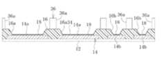
本発明のプリント配線板の一実施形態が、図面を参照して説明される。図1には、実施形態の製造方法により作製されたプリント配線板10の一部が拡大して示されている。プリント配線板10は、コア基板(図示せず)の片面または両面に所定の回路パターンを有する導体層と樹脂絶縁層とを交互に積層してなるコア付き基板であってよい。コア基板の両面に導体層を形成する場合には、コア基板を介して対向する導体層同士は、スルーホール導体(図示せず)を介して接続されていてもよい。あるいは、プリント配線板10は、コア基板の代わりに支持板(図示せず)上で導体層と樹脂絶縁層とを交互に積層した後、支持板を除去してなるコアレス基板であってもよい。いずれにせよ、プリント配線板10は、図1に示すように、少なくとも1層の樹脂絶縁層のうち最外に配置されたものである基部絶縁層12と、基部絶縁層12上に形成された、所定の回路パターンを有する導体層14と、基部絶縁層12および導体層14上に形成されたソルダーレジスト層16とを備えている。基部絶縁層12の下層には他の複数の導体層および樹脂絶縁層が交互に設けられている場合が多いが、図では省略されている。しかし、プリント配線板10は、1層の基部絶縁層12と1層の導体層14とからなるものでもよい。<About the printed wiring board of the present invention>
An embodiment of the printed wiring board of the present invention will be described with reference to the drawings. FIG. 1 shows a part of the printed
基部絶縁層12は、例えばシリカやアルミナ等の無機フィラーとエポキシ系樹脂とを含む樹脂組成物等で構成することができる。導体層14は導電性金属、例えば銅を主成分とする金属で形成される。 The
ソルダーレジスト層16は、導体層14の一部を第1の導体パッド14aとして露出させる第1の開口16aと、第1の開口16aよりも径が小さく導体層14の他の一部を第2の導体パッド14bとして露出させる第2の開口16bとを有している。第1の開口16aのアスペクト比、つまり底部の口径に対する深さの比は0.5以下とすることができる。第2の開口16bのアスペクト比、つまり底部の口径に対する深さの比0.6以上とすることができる。 The
第1および第2の導体パッド14a、14b上には下地層18がそれぞれ形成されていてよい。下地層18としては、第1および第2の導体パッド14a、14bの表面に形成されたニッケル層とニッケル層上に形成されたパラジウム層とパラジウム層上に形成された金層とを例示することができる。その他、ニッケル層とニッケル層上に形成された金層とを例示することができる。下地層18は形成しなくてもよい。 The
プリント配線板10はさらに、第1の導体パッド14a上に下地層18を介して形成された第1のバンプ20と、第2の導体パッド14b上に下地層18を介して形成され、第1のバンプ20よりも小径の第2のバンプ22とを備えている。下地層18を形成しない場合、第1および第2のバンプ20、22は第1および第2の導体パッド14a、14b上に直接形成することができる。第1のバンプ20は電源もしくはグランド線との接続に用いることができる。第1のバンプ20よりも径の小さい第2のバンプ22は信号線との接続に用いることができる。 The printed
本発明のプリント配線板10において大径バンプを構成する第1のバンプ20は、第1の開口16a内に形成された第1のベースめっき層24と、第1のベースめっき層24上に例えばニッケルを主成分とする中間層26を介して形成された第1のトップめっき層28とを有する。中間層26の厚みは7μm以下とすることが好ましい。中間層26は形成しなくてもよい。中間層26を形成しない場合、第1のトップめっき層28は第1のベースめっき層24上に直接形成することができる。 In the printed
第1のベースめっき層24は、導電性金属、好ましくは銅を主成分とする金属から形成されている。第1のベースめっき層24はソルダーレジスト層16の表面(基部絶縁層12とは反対側の面)を超える高さまで形成する。これにより第1のバンプ20が第1の開口16a内に安定して保持される。ソルダーレジスト層16の表面からの第1のベースめっき層24の厚みB1は3μm〜20μmの範囲内とすることが好ましい。 The first
第1のトップめっき層28は、第1のベースめっき層24よりも融点が低くリフロー処理により溶融して図1に示すような略半球状に整形される金属、例えばスズを主成分とする金属からなる。第1のトップめっき層28の厚み(第1のバンプ20の外周面において第1のトップめっき層28の下端から第1のトップめっき層の頂部までの垂直方向の距離)A1は5μm〜45μmの範囲とすることが好ましい。第1のトップめっき層28の厚みA1をこの範囲とすることで、第1のバンプ20と、プリント配線板10に実装される半導体チップやメモリなど電子部品の接続パッド(図示せず)との間で良好な接続信頼性が得られる。 The first
本発明のプリント配線板10において小径バンプを構成する第2のバンプ22は、第2の開口16b内に形成された第2のベースめっき層30と、第2のベースめっき層30上に例えばニッケルを主成分とする中間層26を介して形成された第2のトップめっき層32とを有する。中間層26の厚みは7μm以下とすることが好ましい。中間層26は形成しなくてもよい。中間層26を形成しない場合、第2のトップめっき層32は第2のベースめっき層30上に直接形成することができる。 In the printed
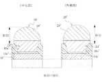
第2のベースめっき層30は、導電性金属、好ましくは銅を主成分とする金属から形成されている。第2のベースめっき層30はソルダーレジスト層16の表面(基部絶縁層12とは反対側の面)を超える高さまで形成することが好ましい。これにより第2のバンプ22が第2の開口16b内に安定して保持される。ソルダーレジスト層16の表面からの第2のベースめっき層30の厚みB2は3μm〜20μmの範囲内とすることが好ましい。第2のベースめっき層30は上面中央部分に第2の窪み30aを有する。すなわち、第2のベースめっき層30の上面中央部分は上面外周部分よりも低い位置に形成されている。 The second
第2のトップめっき層32は、第2のベースめっき層30よりも融点が低くリフロー処理により溶融して図1に示すような略半球状に整形される金属、例えばスズを主成分とする金属からなる。第2のトップめっき層32の厚み(第2のバンプ22の外周面において第2のトップめっき層32の下端から第2のトップめっき層32の頂部までの垂直方向の距離)A2は5μm〜45μmの範囲とすることが好ましい。第2のトップめっき層32の厚みA2をこの範囲とすることで、第2のバンプ22と、プリント配線板10に実装される半導体チップやメモリなど電子部品の接続パッド(図示せず)との間で良好な接続信頼性が得られる。 The second
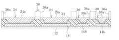
本発明に係るプリント配線板では、大径バンプを構成する複数の第1のバンプ20において、第1のバンプ20の径が、プリント配線板の中央に向かって大きく、複数の第1のバンプ20の最上位置が略同一である。 In the printed wiring board according to the present invention, in the plurality of
具体的な態様の一例として、図2に示すように、第1のトップめっき層28のリフロー前において、プリント配線板の外周部に位置する外周部バンプの第1のベースめっき層24の径をR1とし、プリント配線板の中央部に位置する中央部バンプの第1のベースめっき層24の径をR3とすると、第1のトップめっき層28のリフロー後における第1のバンプ20の径は、外形部バンプにおいてR1となり、中央部バンプにおいてR3となる。この外周部バンプと中央部バンプとの関係を、R3>R1とする。この際、第1のベースめっき層24の下地層18と接触する部分の径をR11とすると、R11は外周部バンプおよび中央部バンプにおいて同じであり、R1およびR3との関係はR3>R1>R11となる。また、第1のバンプ20のバンプ高さを、外周部バンプでBH1、中央部バンプでBH3とすると、略BH1=BH3の関係となる。 As an example of a specific embodiment, as shown in FIG. 2, before the reflow of the first
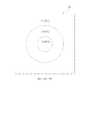
具体的な態様の他の例として、図3に示すように、プリント配線板10を中央部Z3、中間部Z2および外周部Z1と分け、中央部Z3に存在する第1のバンプ20の径をR3、中間部Z2に存在する第1のバンプ20の径をR2、外周部Z1に存在する第1のバンプ20の径をR3としたとき、R3>R2>R1とすることができる。 As another example of a specific embodiment, as shown in FIG. 3, the printed
<本発明のプリント配線板の製造方法について>
以下、本発明に係る図1に示すプリント配線板10の製造方法を、図4A〜図4Hを参照して説明する。<About the manufacturing method of the printed wiring board of the present invention>
Hereinafter, a method for manufacturing the printed
図4Aには、公知の方法を用いて、基部絶縁層12上に所定の回路パターンを有する導体層14およびソルダーレジスト層16が形成された中間体が示されている。基部絶縁層12の下層には他の複数の導体層および樹脂絶縁層が交互に形成されている場合が多いが、図では省略されている。複数の導体層および樹脂絶縁層はコア基板上もしくは後に除去可能な支持板上で積層することができる。しかし、プリント配線板10は、基部絶縁層12としての1層の樹脂絶縁層と1層の導体層14とからなるものでもよく、この場合この樹脂絶縁層が基部絶縁層12に相当する。基部絶縁層12には、シリカやアルミナ等の無機フィラーとエポキシ系樹脂とを含むビルドアップ用絶縁樹脂フィルムを用いることができる。ソルダーレジスト層16には、例えば炭酸ガスレーザまたはUV−YAGレーザ等により、導体層14の一部を第1の導体パッド14aとして露出させる第1の開口16aと導体層14の他の一部を第2の導体パッド14bとして露出させる第2の開口16bが形成される。第1の開口16aのアスペクト比は0.5以下とし、第2の開口16bのアスペクト比は0.6以上とするのが好ましい。第1および第2の導体パッド14a、14b上には、めっきにより例えばニッケル層、パラジウム層、金層がこの順に積層されて下地層18が形成される。下地層18は形成しなくてもよい。 FIG. 4A shows an intermediate in which a
図4Bに示されるように、例えば、無電解銅めっき処理等の無電解めっき処理が行われ、中間体の表面(ソルダーレジスト層16の表面および第1および第2の開口16a、16bの側面)上と、下地層18上(下地層18が形成されない場合には導体パッド14a、14b上)にシード層34が形成される。 As shown in FIG. 4B, for example, an electroless plating treatment such as an electroless copper plating treatment is performed, and the surface of the intermediate body (the surface of the solder resist
図4Cに示されるように、シード層34上に、第1および第2のバンプ20、22(図1)の形成予定部位に開口36aを有する所定パターンのめっきレジスト36が形成される。 As shown in FIG. 4C, a plating resist 36 having a predetermined pattern having an
図4Dに示されるように、電解めっき処理が行われ、シード層34上の、めっきレジスト36から露出する部分に、例えば銅を主成分とする第1のベースめっき層24および第2のベースめっき層30が形成される。本発明では、この段階で、複数の第1のベースめっき層24の径をプリント配線板の中央に向かって大きくすることで、最終形状の第1のバンプ20の径をプリント配線板の中央に向かって大きくすることができる。 As shown in FIG. 4D, the electrolytic plating treatment is performed, and the portion of the
また、第1および第2のベースめっき層24、30を形成する際には、ソルダーレジスト層16の表面からの第1のベースめっき層24の厚みおよび第2のベースめっき層30の厚みが3μm〜20μmの範囲内となるよう、第1および第2のベースめっき層24、30のめっき厚を調整するのが好ましい。 When forming the first and second
図4Eに示されるように、例えば電解めっき処理が行われ、第1および第2のベースめっき層24,30上に例えばニッケルを主成分とする中間層26が形成される。中間層26の厚みは好ましくは7μm以下とする。中間層26は形成しなくてもよい。 As shown in FIG. 4E, for example, an electrolytic plating treatment is performed, and an
図4Fに示されるように、電解めっき処理が行われ、第1および第2のベースめっき層24,30上に中間層26を介在して第1および第2のトップめっき層28,32が形成される。第1および第2のトップめっき層28,32は、第1および第2のベースめっき層24,30よりも融点が低くリフロー処理により溶融して略半球状に整形される金属、例えばスズを主成分とする金属からなる。第1および第2のトップめっき層28,32の厚みは5μm〜45μmの範囲とすることが好ましい。 As shown in FIG. 4F, the electrolytic plating treatment is performed to form the first and second
図4Gに示されるように、めっきレジスト36が剥離される。また、めっきレジスト36の除去により露出したシード層34の部分がエッチングにより除去される。 As shown in FIG. 4G, the plating resist 36 is peeled off. Further, the portion of the
図4Hに示されるように、リフロー処理が行われ、第1のトップめっき層28および第2のトップめっき層32が略半球状に整形される。リフロー処理により、第1および第2の導体パッド14a、14bに近い側から銅層、銅/ニッケル合金層、ニッケル層、ニッケル/スズ合金層、スズ層からなる第1のバンプ20および第2のバンプ22が形成される。中間層26が形成されていない場合には、第1および第2の導体パッド14a,14bに近い側から銅層、銅/スズ合金層、スズ層からなる第1のバンプ20および第2のバンプ22が形成される。 As shown in FIG. 4H, a reflow process is performed to shape the first
10 プリント配線板
12 基部絶縁層
14 導体層
14a 第1の導体パッド
14b 第2の導体パッド
16 ソルダーレジスト層
16a 第1の開口
16b 第2の開口
18 下地層
20 第1のバンプ
22 第2のバンプ
24 第1のベースめっき層
24a 第1の窪み
26 中間層
28 第1のトップめっき層
30 第2のベースめっき層
30a 第2の窪み
30b 隆起部
32 第2のトップめっき層
34 シード層
36 めっきレジスト10 Printed
Claims (20)
Translated fromJapanese基部絶縁層と、
前記基部絶縁層上に形成された導体層と、
前記基部絶縁層上および前記導体層上に形成され、かつ、前記導体層の一部を第1の導体パッドとして露出させる第1の開口、および該第1の開口よりも径が小さく前記導体層の他の一部を第2の導体パッドとして露出させる第2の開口を有するソルダーレジスト層と、
前記第1の導体パッド上に形成された第1のバンプと、
前記第2の導体パッド上に形成され、前記第1のバンプよりも小径の第2のバンプと、
を備え、
前記第1のバンプは、前記第1の開口内に形成された第1のベースめっき層と、該第1のベースめっき層上に形成された第1のトップめっき層とを有し、
前記第2のバンプは、前記第2の開口内に形成された第2のベースめっき層と、該第2のベースめっき層上に形成された第2のトップめっき層とを有し、
複数の前記第1のバンプにおいて、第1のバンプの径がプリント配線板の中央に向かって大きく、複数の前記第1のバンプの最上位置が略同一である。It is a printed wiring board
With the base insulation layer,
The conductor layer formed on the base insulating layer and
A first opening formed on the base insulating layer and the conductor layer and exposing a part of the conductor layer as a first conductor pad, and the conductor layer having a diameter smaller than that of the first opening. A solder resist layer having a second opening that exposes the other part as a second conductor pad,
With the first bump formed on the first conductor pad,
A second bump formed on the second conductor pad and having a diameter smaller than that of the first bump,
With
The first bump has a first base plating layer formed in the first opening and a first top plating layer formed on the first base plating layer.
The second bump has a second base plating layer formed in the second opening and a second top plating layer formed on the second base plating layer.
In the plurality of the first bumps, the diameter of the first bump is large toward the center of the printed wiring board, and the uppermost positions of the plurality of the first bumps are substantially the same.
基部絶縁層を形成することと、
前記基部絶縁層上に導体層を形成することと、
前記基部絶縁層上および前記導体層上にソルダーレジスト層を形成することと、
前記ソルダーレジスト層に、前記導体層の一部を第1の導体パッドとして露出させる第1の開口を形成することと、
前記ソルダーレジスト層に、前記第1の開口よりも径が小さく前記導体層の他の一部を第2の導体パッドとして露出させる第2の開口を形成することと、
前記第1の導体パッド上に第1のバンプを形成することと、
前記第2の導体パッド上に、前記第1のバンプよりも小径の第2のバンプを形成することと、を含み、
前記第1のバンプを形成することは、前記第1の開口内に第1のベースめっき層を形成することと、前記第1のベースめっき層上に第1のトップめっき層を形成することと、第1のトップめっき層をリフローして、複数の前記第1のバンプの径を、複数の前記第1のベースめっき層の径をプリント配線板の中央に向かって大きくすることで、プリント配線板の中央に向かって大きくすることと、を含み、
前記第2のバンプを形成することは、前記第2の開口内に第2のベースめっき層を形成することと、前記第2のベースめっき層上に、前記第1のトップめっき層の上面の最上位置より上にある上面を有する第2のトップめっき層を形成することと、第2のトップめっき層をリフローすることと、を含む。It is a manufacturing method of printed wiring boards.
Forming a base insulating layer and
Forming a conductor layer on the base insulating layer and
Forming a solder resist layer on the base insulating layer and the conductor layer,
To form a first opening in the solder resist layer that exposes a part of the conductor layer as a first conductor pad.
To form a second opening in the solder resist layer, which has a diameter smaller than that of the first opening and exposes another part of the conductor layer as a second conductor pad.
Forming a first bump on the first conductor pad and
Including forming a second bump having a diameter smaller than that of the first bump on the second conductor pad.
Forming the first bump means forming a first base plating layer in the first opening and forming a first top plating layer on the first base plating layer. , The first top plating layer is reflowed to increase the diameters of the plurality of first bumps and the diameters of the plurality of first base plating layers toward the center of the printed wiring board. Including increasing towards the center of the board,
Forming the second bump means forming a second base plating layer in the second opening and forming the second base plating layer on the second base plating layer and on the upper surface of the first top plating layer. It includes forming a second top plating layer having an upper surface above the top position and reflowing the second top plating layer.
Priority Applications (1)
| Application Number | Priority Date | Filing Date | Title |
|---|---|---|---|
| JP2019118255AJP7257273B2 (en) | 2019-06-26 | 2019-06-26 | Printed wiring board and manufacturing method thereof |
Applications Claiming Priority (1)
| Application Number | Priority Date | Filing Date | Title |
|---|---|---|---|
| JP2019118255AJP7257273B2 (en) | 2019-06-26 | 2019-06-26 | Printed wiring board and manufacturing method thereof |
Publications (2)
| Publication Number | Publication Date |
|---|---|
| JP2021005609Atrue JP2021005609A (en) | 2021-01-14 |
| JP7257273B2 JP7257273B2 (en) | 2023-04-13 |
Family
ID=74099451
Family Applications (1)
| Application Number | Title | Priority Date | Filing Date |
|---|---|---|---|
| JP2019118255AActiveJP7257273B2 (en) | 2019-06-26 | 2019-06-26 | Printed wiring board and manufacturing method thereof |
Country Status (1)
| Country | Link |
|---|---|
| JP (1) | JP7257273B2 (en) |
Cited By (2)
| Publication number | Priority date | Publication date | Assignee | Title |
|---|---|---|---|---|
| JP2022121157A (en)* | 2021-02-08 | 2022-08-19 | イビデン株式会社 | Printed wiring board and manufacturing method thereof |
| JP2022121152A (en)* | 2021-02-08 | 2022-08-19 | イビデン株式会社 | Printed wiring board and manufacturing method thereof |
Citations (7)
| Publication number | Priority date | Publication date | Assignee | Title |
|---|---|---|---|---|
| JP2003142811A (en)* | 2001-11-06 | 2003-05-16 | Ngk Spark Plug Co Ltd | Wiring board and manufacturing method therefor |
| JP2003332497A (en)* | 2002-05-10 | 2003-11-21 | Matsushita Electric Ind Co Ltd | Grid array type electronic component, circuit board, and reflow soldering method between electronic component and circuit board |
| WO2007086551A1 (en)* | 2006-01-27 | 2007-08-02 | Ibiden Co., Ltd. | Printed-circuit board, and method for manufacturing the same |
| JP2012231130A (en)* | 2011-04-25 | 2012-11-22 | Samsung Electro-Mechanics Co Ltd | Package substrate and manufacturing method for the same |
| JP2013149948A (en)* | 2011-12-20 | 2013-08-01 | Ngk Spark Plug Co Ltd | Wiring board and manufacturing method of the same |
| JP2013172073A (en)* | 2012-02-22 | 2013-09-02 | Ibiden Co Ltd | Printed wiring board and manufacturing method of the same |
| JP2017152646A (en)* | 2016-02-26 | 2017-08-31 | 富士通株式会社 | Electronic components, electronic devices and electronic equipment |
- 2019
- 2019-06-26JPJP2019118255Apatent/JP7257273B2/enactiveActive
Patent Citations (7)
| Publication number | Priority date | Publication date | Assignee | Title |
|---|---|---|---|---|
| JP2003142811A (en)* | 2001-11-06 | 2003-05-16 | Ngk Spark Plug Co Ltd | Wiring board and manufacturing method therefor |
| JP2003332497A (en)* | 2002-05-10 | 2003-11-21 | Matsushita Electric Ind Co Ltd | Grid array type electronic component, circuit board, and reflow soldering method between electronic component and circuit board |
| WO2007086551A1 (en)* | 2006-01-27 | 2007-08-02 | Ibiden Co., Ltd. | Printed-circuit board, and method for manufacturing the same |
| JP2012231130A (en)* | 2011-04-25 | 2012-11-22 | Samsung Electro-Mechanics Co Ltd | Package substrate and manufacturing method for the same |
| JP2013149948A (en)* | 2011-12-20 | 2013-08-01 | Ngk Spark Plug Co Ltd | Wiring board and manufacturing method of the same |
| JP2013172073A (en)* | 2012-02-22 | 2013-09-02 | Ibiden Co Ltd | Printed wiring board and manufacturing method of the same |
| JP2017152646A (en)* | 2016-02-26 | 2017-08-31 | 富士通株式会社 | Electronic components, electronic devices and electronic equipment |
Cited By (4)
| Publication number | Priority date | Publication date | Assignee | Title |
|---|---|---|---|---|
| JP2022121157A (en)* | 2021-02-08 | 2022-08-19 | イビデン株式会社 | Printed wiring board and manufacturing method thereof |
| JP2022121152A (en)* | 2021-02-08 | 2022-08-19 | イビデン株式会社 | Printed wiring board and manufacturing method thereof |
| JP7568533B2 (en) | 2021-02-08 | 2024-10-16 | イビデン株式会社 | Printed wiring board and its manufacturing method |
| JP7599348B2 (en) | 2021-02-08 | 2024-12-13 | イビデン株式会社 | Printed wiring board and its manufacturing method |
Also Published As
| Publication number | Publication date |
|---|---|
| JP7257273B2 (en) | 2023-04-13 |
Similar Documents
| Publication | Publication Date | Title |
|---|---|---|
| US11083086B2 (en) | Printed wiring board and method for manufacturing printed wiring board | |
| JP2021052104A (en) | Printed wiring board and method for manufacturing the same | |
| US11963298B2 (en) | Printed wiring board and method for manufacturing printed wiring board | |
| US11304307B2 (en) | Printed wiring board and method for manufacturing printed wiring board | |
| JP5157455B2 (en) | Semiconductor device | |
| JP7257273B2 (en) | Printed wiring board and manufacturing method thereof | |
| US11109481B2 (en) | Method for manufacturing printed wiring board and printed wiring board | |
| JP2020136652A (en) | Manufacturing method of printed wiring board and printed wiring board | |
| US12010794B2 (en) | Printed wiring board and method for manufacturing the same | |
| US20220330427A1 (en) | Printed wiring board and method for manufacturing printed wiring board | |
| JP2021036555A (en) | Print circuit board and manufacturing method therefor | |
| JP2021072337A (en) | Manufacturing method of printed wiring board | |
| JP7336258B2 (en) | Printed wiring board and manufacturing method thereof | |
| JP7599348B2 (en) | Printed wiring board and its manufacturing method | |
| JP7568533B2 (en) | Printed wiring board and its manufacturing method | |
| JP2021027224A (en) | Method for manufacturing printed wiring board | |
| JP5479959B2 (en) | Manufacturing method of wiring board having solder bump, mask for mounting solder ball | |
| JP2021040090A (en) | Printed wiring board and manufacturing method thereof | |
| JP2021072338A (en) | Manufacturing method of printed wiring board | |
| JP7257175B2 (en) | Printed wiring board and printed wiring board manufacturing method | |
| JP2021072339A (en) | Printed wiring board and method for manufacturing the same | |
| JP2022018196A (en) | Manufacturing method of printed wiring board and printed wiring board | |
| JP2022017678A (en) | Printed wiring board and manufacturing method thereof | |
| JP2021027225A (en) | Printed wiring board | |
| JP2021036554A (en) | Manufacturing method for print circuit board |
Legal Events
| Date | Code | Title | Description |
|---|---|---|---|
| A621 | Written request for application examination | Free format text:JAPANESE INTERMEDIATE CODE: A621 Effective date:20220323 | |
| A977 | Report on retrieval | Free format text:JAPANESE INTERMEDIATE CODE: A971007 Effective date:20230228 | |
| TRDD | Decision of grant or rejection written | ||
| A01 | Written decision to grant a patent or to grant a registration (utility model) | Free format text:JAPANESE INTERMEDIATE CODE: A01 Effective date:20230308 | |
| A61 | First payment of annual fees (during grant procedure) | Free format text:JAPANESE INTERMEDIATE CODE: A61 Effective date:20230403 | |
| R150 | Certificate of patent or registration of utility model | Ref document number:7257273 Country of ref document:JP Free format text:JAPANESE INTERMEDIATE CODE: R150 |