Movatterモバイル変換


[0]ホーム

URL:


JP2021003357A - Suction tool - Google Patents

Suction tool
Download PDF

Info

Publication number
JP2021003357A
JP2021003357AJP2019118767AJP2019118767AJP2021003357AJP 2021003357 AJP2021003357 AJP 2021003357AJP 2019118767 AJP2019118767 AJP 2019118767AJP 2019118767 AJP2019118767 AJP 2019118767AJP 2021003357 AJP2021003357 AJP 2021003357A
Authority
JP
Japan
Prior art keywords
suction port
brush
shaft member
suction
suction tool
Prior art date
Legal status (The legal status is an assumption and is not a legal conclusion. Google has not performed a legal analysis and makes no representation as to the accuracy of the status listed.)
Granted
Application number
JP2019118767A
Other languages
Japanese (ja)
Other versions
JP7200848B2 (en
Inventor
龍一 内田
Ryuichi Uchida
龍一 内田
諒太 遠藤
Ryota Endo
諒太 遠藤
亮介 赤石
Ryosuke Akaishi
亮介 赤石
Current Assignee (The listed assignees may be inaccurate. Google has not performed a legal analysis and makes no representation or warranty as to the accuracy of the list.)
Mitsubishi Electric Home Appliance Co Ltd
Mitsubishi Electric Corp
Original Assignee
Mitsubishi Electric Home Appliance Co Ltd
Mitsubishi Electric Corp
Priority date (The priority date is an assumption and is not a legal conclusion. Google has not performed a legal analysis and makes no representation as to the accuracy of the date listed.)
Filing date
Publication date
Application filed by Mitsubishi Electric Home Appliance Co Ltd, Mitsubishi Electric CorpfiledCriticalMitsubishi Electric Home Appliance Co Ltd
Priority to JP2019118767ApriorityCriticalpatent/JP7200848B2/en
Publication of JP2021003357ApublicationCriticalpatent/JP2021003357A/en
Application grantedgrantedCritical
Publication of JP7200848B2publicationCriticalpatent/JP7200848B2/en
Activelegal-statusCriticalCurrent
Anticipated expirationlegal-statusCritical

Links

Images

Landscapes

Abstract

Translated fromJapanese

【課題】能力の低下及び回転ブラシの大型化のいずれも招くことなく、回転ブラシの着脱が容易である吸込具を提供する。【解決手段】この発明に係る吸込具5は、吸込口23が形成された吸込口体18と、吸込口体18の内部に吸込口23と通じて形成されたブラシ室27の内側に吸込口23に臨んで設けられ、回転軸を中心に回転可能な回転ブラシ40と、を備える。回転ブラシ40は、回転軸と平行に移動して吸込口体18の側面に形成された開口54を通してブラシ室27の内側に着脱可能であるとともに、外周部に清掃体41が取り付けられた清掃体保持部42と、清掃体保持部42を吸込口体18に対して回転軸を中心に回転可能に支持する軸部材と、軸部材の開口54側の端部に設けられ、着脱時に使用者が把持するための把持部48と、軸部材の内側に設けられ、把持部48を回転軸に沿ってブラシ室27の外側に押し出す弾性体49と、を備える。【選択図】図18PROBLEM TO BE SOLVED: To provide a suction tool in which a rotating brush can be easily attached and detached without causing a decrease in capacity and an increase in size of the rotating brush. SOLUTION: A suction tool 5 according to the present invention has a suction port body 18 in which a suction port 23 is formed, and a suction port inside a brush chamber 27 formed inside the suction port body 18 through the suction port 23. A rotating brush 40, which is provided facing the 23 and is rotatable about a rotation axis, is provided. The rotary brush 40 moves in parallel with the rotation axis and can be attached to and detached from the inside of the brush chamber 27 through an opening 54 formed on the side surface of the suction port body 18, and the cleaning body 41 is attached to the outer peripheral portion. A holding portion 42, a shaft member that rotatably supports the cleaning body holding portion 42 with respect to the suction port body 18 around a rotation shaft, and an end portion of the shaft member on the opening 54 side are provided so that the user can attach or detach the holding portion 42. A gripping portion 48 for gripping and an elastic body 49 provided inside the shaft member and pushing the gripping portion 48 to the outside of the brush chamber 27 along the rotation axis are provided. [Selection diagram] FIG. 18

Description

Translated fromJapanese

この発明は、電気掃除機に使用可能な吸込具に関するものである。 The present invention relates to a suction tool that can be used in a vacuum cleaner.

電気掃除機用の吸込具においては、外郭をなすケースと、このケース内において駆動部により回転駆動される回転ブラシと、を備え、ケースには、回転ブラシをケース内に取付け又は取外しするための開口部が設けられ、回転ブラシは、取り外しのときは開口部から引き抜かれるようになっているものがある。そして、回転ブラシには、ケース内に取付け又は取外しするときに把持するための一部分がケース外に露出し他の部分がケース内に収容される把持部と、この把持部を回転ブラシの取外し方向に付勢する付勢手段が把持部内に設けられ、回転ブラシを取り外す際には、付勢手段により把持部をケースの表面から取り出し方向に突出させるものが知られている(例えば、特許文献1の図16等を参照)。 The suction tool for a vacuum cleaner includes a case forming an outer shell and a rotary brush that is rotationally driven by a drive unit in the case, and the case is for attaching or detaching the rotary brush into or from the case. Some rotary brushes are provided with an opening so that they can be pulled out of the opening when they are removed. Then, the rotary brush has a grip portion in which a part for gripping is exposed to the outside of the case and the other portion is housed in the case when it is attached or detached in the case, and the grip portion is in the direction of removing the rotary brush. It is known that an urging means for urging the brush is provided in the grip portion, and when the rotating brush is removed, the urging means projects the grip portion from the surface of the case in the taking-out direction (for example, Patent Document 1). See FIG. 16 and the like).

特開2013−022277号公報Japanese Unexamined Patent Publication No. 2013-022277

しかしながら、特許文献1に示されるような吸込具においては、回転ブラシを取り外す際に把持部内に設けられた弾性ばね等の付勢手段が、把持部をケース表面から突出させる。そして、把持部は、一部分がケース外に露出し他の部分がケース内に収容される。このため、把持部は、付勢手段をその内部に収容し、かつ、ケース表面から突出した状態においても、その一部がケース内に残るだけの大きさが必要である。したがって、回転ブラシの全長に対し把持部が占める割合が大きくなり、ブラシ(清掃体)の幅が狭くなってしまう。そして、回転ブラシにおける清掃体の幅が狭くなると、清掃能力の低下を招く。あるいは、一定の清掃能力を確保するためには、回転ブラシ及び吸込具全体の大型化が必要になる。 However, in a suction tool as shown in Patent Document 1, an urging means such as an elastic spring provided in the grip portion when the rotary brush is removed causes the grip portion to protrude from the case surface. Then, a part of the grip portion is exposed to the outside of the case and the other portion is housed in the case. For this reason, the grip portion needs to have a size that accommodates the urging means inside the grip portion and a part of the grip portion remains in the case even when it protrudes from the case surface. Therefore, the ratio of the grip portion to the total length of the rotating brush becomes large, and the width of the brush (cleaning body) becomes narrow. When the width of the cleaning body in the rotating brush is narrowed, the cleaning ability is lowered. Alternatively, in order to secure a certain cleaning ability, it is necessary to increase the size of the rotating brush and the suction tool as a whole.

この発明は、このような課題を解決するためになされたものである。その目的は、清掃能力の低下及び回転ブラシの大型化のいずれも招くことなく、回転ブラシの着脱が容易である吸込具を提供することにある。 The present invention has been made to solve such a problem. An object of the present invention is to provide a suction tool in which the rotating brush can be easily attached and detached without causing a decrease in cleaning ability and an increase in the size of the rotating brush.

この発明に係る吸込具は、吸込口が形成された吸込口体と、前記吸込口体の内部に前記吸込口と通じて形成されたブラシ室の内側に前記吸込口に臨んで設けられ、回転軸を中心に回転可能な回転ブラシと、を備え、前記回転ブラシは、前記回転軸と平行に移動して前記吸込口体の側面に形成された開口を通して前記ブラシ室の内側に着脱可能であるとともに、外周部に清掃体が取り付けられた清掃体保持部と、前記清掃体保持部を前記吸込口体に対して前記回転軸を中心に回転可能に支持する軸部材と、前記軸部材の前記開口側の端部に設けられ、着脱時に使用者が把持するための把持部と、前記軸部材の内側に設けられ、前記把持部を前記回転軸に沿って前記ブラシ室の外側に押し出す弾性体と、を備える。 The suction tool according to the present invention is provided to face the suction port inside a suction port body in which a suction port is formed and a brush chamber formed inside the suction port body through the suction port and rotate. A rotating brush that can rotate about a shaft is provided, and the rotating brush can be attached to and detached from the inside of the brush chamber through an opening formed on the side surface of the suction port body by moving in parallel with the rotating shaft. At the same time, a cleaning body holding portion having a cleaning body attached to an outer peripheral portion, a shaft member that rotatably supports the cleaning body holding portion with respect to the suction port body about the rotation axis, and the shaft member. An elastic body provided at the end on the opening side for the user to grip at the time of attachment / detachment, and an elastic body provided inside the shaft member and pushing the grip portion to the outside of the brush chamber along the rotation axis. And.

この発明に係る吸込具によれば、清掃能力の低下及び回転ブラシの大型化のいずれも招くことなく、回転ブラシの着脱が容易であるという効果を奏する。 According to the suction tool according to the present invention, there is an effect that the rotating brush can be easily attached and detached without causing a decrease in cleaning ability and an increase in size of the rotating brush.

この発明の実施の形態1に係る吸込具を備えた電気掃除機の正面図である。It is a front view of the vacuum cleaner provided with the suction tool which concerns on Embodiment 1 of this invention.この発明の実施の形態1に係る吸込具を備えた電気掃除機の斜視図である。It is a perspective view of the electric vacuum cleaner provided with the suction tool which concerns on Embodiment 1 of this invention.この発明の実施の形態1に係る電気掃除機の本体の正面図である。It is a front view of the main body of the vacuum cleaner which concerns on Embodiment 1 of this invention.図3中の断面A−Aによる断面図である。It is sectional drawing which shows the cross section AA in FIG.この発明の実施の形態1に係る電気掃除機の管体の斜視図である。It is a perspective view of the tube body of the vacuum cleaner which concerns on Embodiment 1 of this invention.この発明の実施の形態1に係る電気掃除機の管体の下面図である。It is a bottom view of the tube body of the vacuum cleaner which concerns on Embodiment 1 of this invention.図6中の断面B−Bによる断面図である。It is sectional drawing which shows the cross section BB in FIG.この発明の実施の形態1に係る吸込具の側面図である。It is a side view of the suction tool which concerns on Embodiment 1 of this invention.この発明の実施の形態1に係る吸込具の上面図である。It is a top view of the suction tool which concerns on Embodiment 1 of this invention.この発明の実施の形態1に係る吸込具の底面図である。It is a bottom view of the suction tool which concerns on Embodiment 1 of this invention.図10中の断面C−Cによる断面図である。It is sectional drawing which shows the cross section CC in FIG.この発明の実施の形態1に係る吸込具の接続部の可動範囲を示す断面図である。It is sectional drawing which shows the movable range of the connection part of the suction tool which concerns on Embodiment 1 of this invention.この発明の実施の形態1に係る電気掃除機とスタンドの側面図である。It is a side view of the vacuum cleaner and the stand which concerns on Embodiment 1 of this invention.この発明の実施の形態1に係る電気掃除機とスタンドの斜視図である。It is a perspective view of the vacuum cleaner and the stand which concerns on Embodiment 1 of this invention.図10中の断面D−Dによる断面図である。It is sectional drawing which shows the cross section DD in FIG.この発明の実施の形態1に係る吸込具の要部を拡大した底面図である。It is the bottom view which enlarged the main part of the suction tool which concerns on Embodiment 1 of this invention.この発明の実施の形態1に係る吸込具の要部を拡大した断面図である。FIG. 5 is an enlarged cross-sectional view of a main part of the suction tool according to the first embodiment of the present invention.この発明の実施の形態1に係る吸込具の要部を拡大した断面図である。FIG. 5 is an enlarged cross-sectional view of a main part of the suction tool according to the first embodiment of the present invention.この発明の実施の形態1に係る吸込具の斜視図である。It is a perspective view of the suction tool which concerns on Embodiment 1 of this invention.この発明の実施の形態1に係る吸込具の斜視図である。It is a perspective view of the suction tool which concerns on Embodiment 1 of this invention.この発明の実施の形態1に係る吸込具の正面図である。It is a front view of the suction tool which concerns on Embodiment 1 of this invention.

この発明を実施するための形態について添付の図面を参照しながら説明する。各図において、同一又は相当する部分には同一の符号を付して、重複する説明は適宜に簡略化又は省略する。なお、本発明は以下の実施の形態に限定されることなく、本発明の趣旨を逸脱しない範囲で種々変形することが可能である。 A mode for carrying out the present invention will be described with reference to the accompanying drawings. In each figure, the same or corresponding parts are designated by the same reference numerals, and duplicate description will be appropriately simplified or omitted. The present invention is not limited to the following embodiments, and various modifications can be made without departing from the spirit of the present invention.

実施の形態1.
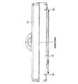
図1から図21を参照しながら、この発明の実施の形態1について説明する。図1は吸込具を備えた電気掃除機の正面図である。図2は吸込具を備えた電気掃除機の斜視図である。図3は電気掃除機の本体の正面図である。図4は図3中の断面A−Aによる断面図である。図5は電気掃除機の管体の斜視図である。図6は電気掃除機の管体の下面図である。図7は図6中の断面B−Bによる断面図である。図8は吸込具の側面図である。図9は吸込具の上面図である。図10は吸込具の底面図である。図11は図10中の断面C−Cによる断面図である。図12は吸込具の接続部の可動範囲を示す断面図である。図13は電気掃除機とスタンドの側面図である。図14は電気掃除機とスタンドの斜視図である。図15は図10中の断面D−Dによる断面図である。図16は吸込具の要部を拡大した底面図である。図17及び図18は吸込具の要部を拡大した断面図である。図19及び図20は吸込具の斜視図である。そして、図21は吸込具の正面図である。
Embodiment 1.
The first embodiment of the present invention will be described with reference to FIGS. 1 to 21. FIG. 1 is a front view of a vacuum cleaner equipped with a suction tool. FIG. 2 is a perspective view of a vacuum cleaner equipped with a suction tool. FIG. 3 is a front view of the main body of the vacuum cleaner. FIG. 4 is a cross-sectional view taken along the cross section AA in FIG. FIG. 5 is a perspective view of the tube body of the vacuum cleaner. FIG. 6 is a bottom view of the tube body of the vacuum cleaner. FIG. 7 is a cross-sectional view taken along the cross section BB in FIG. FIG. 8 is a side view of the suction tool. FIG. 9 is a top view of the suction tool. FIG. 10 is a bottom view of the suction tool. FIG. 11 is a cross-sectional view taken along the cross section CC in FIG. FIG. 12 is a cross-sectional view showing a movable range of the connecting portion of the suction tool. FIG. 13 is a side view of the vacuum cleaner and the stand. FIG. 14 is a perspective view of the vacuum cleaner and the stand. FIG. 15 is a cross-sectional view taken along the cross section DD in FIG. FIG. 16 is an enlarged bottom view of a main part of the suction tool. 17 and 18 are enlarged cross-sectional views of a main part of the suction tool. 19 and 20 are perspective views of the suction tool. FIG. 21 is a front view of the suction tool.

以下の説明では、塵埃及びその他のゴミを総称して単に「塵埃」と呼ぶ場合がある。また、塵埃が混じった空気を「含塵空気」と呼ぶ場合がある。そして、塵埃が取り除かれた空気を「清浄空気」と呼ぶ場合がある。また、いくつかの図において、前後及び上下の各方向を矢印で示して特定する。左右方向は、前後方向及び上下方向の両方に直交する方向である。基本的に、被清掃面に近い側を「下」、その反対を「上」と定める。また、主清掃方向つまり清掃時に腕を押し出す方向を「前」、その反対に腕を引く方向を「後」と定める。 In the following description, dust and other dust may be collectively referred to simply as "dust". In addition, air mixed with dust may be referred to as "dust-containing air". The air from which dust has been removed may be referred to as "clean air". Further, in some figures, each direction of front-back and up-down is indicated by an arrow to specify. The left-right direction is a direction orthogonal to both the front-back direction and the up-down direction. Basically, the side closer to the surface to be cleaned is defined as "lower" and the opposite is defined as "upper". In addition, the main cleaning direction, that is, the direction in which the arm is pushed out during cleaning is defined as "front", and the opposite direction in which the arm is pulled is defined as "rear".

この実施の形態に係る吸込具5は、電気掃除機1に取り付けて使用される。ここで説明する電気掃除機1は、図1及び図2に示すように、コードレスタイプの縦型電気掃除機である。これらの図に示すように、電気掃除機1は、主な構成要素として、吸込具5の他に、本体3及び管体4を備えている。図2から図4に示すように、本体3は、ハンドル15、外郭部16及び集塵部17を備えている。ハンドル15は、電気掃除機1の使用中に使用者が手で握る部位である。使用者は、ハンドル15を握ることで電気掃除機1の本体3を把持できる。 Thesuction tool 5 according to this embodiment is used by being attached to the vacuum cleaner 1. The vacuum cleaner 1 described here is a cordless type vertical vacuum cleaner as shown in FIGS. 1 and 2. As shown in these figures, the vacuum cleaner 1 includes amain body 3 and apipe body 4 in addition to thesuction tool 5 as main components. As shown in FIGS. 2 to 4, themain body 3 includes ahandle 15, anouter shell portion 16, and adust collecting portion 17. Thehandle 15 is a portion that the user holds by hand while using the vacuum cleaner 1. The user can grasp themain body 3 of the vacuum cleaner 1 by grasping thehandle 15.

外郭部16は、本体3の外郭すなわち外側の覆いをなす部材である。本体3の外郭部16には、図4に示すように電動送風機66及びバッテリ62が内蔵されている。電動送風機66は電気掃除機1の吸引風を生成するためのものである。バッテリ62は、電動送風機66を駆動するための電力を供給するための二次電池である。 Theouter shell portion 16 is a member that forms the outer shell, that is, the outer cover of themain body 3. As shown in FIG. 4, anelectric blower 66 and abattery 62 are built in theouter shell portion 16 of themain body 3. Theelectric blower 66 is for generating the suction air of the vacuum cleaner 1. Thebattery 62 is a secondary battery for supplying electric power for driving theelectric blower 66.

外郭部16は、ケース部61及び接続管部63を備えている。接続管部63は、管体4が着脱可能に連結される中空筒状の部材である。接続管部63は、塵埃を吸い込むための接続口68を有する。接続口68は、接続管部63の一端に形成された開口である。接続管部63の内部には、接続口68を通過した含塵空気の気流を集塵部17へ導く風路が形成されている。接続管部63の他端には、ハンドル15の一端が外見上連続するようにして配置されている。ハンドル15の他端側には、操作部65が設けられている。 Theouter shell portion 16 includes acase portion 61 and a connectingpipe portion 63. The connectingpipe portion 63 is a hollow tubular member to which thepipe body 4 is detachably connected. Theconnection pipe portion 63 has aconnection port 68 for sucking in dust. Theconnection port 68 is an opening formed at one end of theconnection pipe portion 63. Inside the connectingpipe portion 63, an air passage is formed to guide the airflow of dust-containing air passing through the connectingport 68 to thedust collecting portion 17. At the other end of the connectingpipe portion 63, one end of thehandle 15 is arranged so as to be apparently continuous. Anoperation unit 65 is provided on the other end side of thehandle 15.

ケース部61の内部には、バッテリ62、電動送風機66及び制御部67が収容されている。制御部67は、電動送風機66の動作の制御するための回路等を備えている。バッテリ62は、ケース部61の下部に配置される。また、バッテリ62は接続管部63の中心軸の延長線上に配置される。 Abattery 62, anelectric blower 66, and acontrol unit 67 are housed inside thecase unit 61. Thecontrol unit 67 includes a circuit for controlling the operation of theelectric blower 66 and the like. Thebattery 62 is arranged below thecase portion 61. Further, thebattery 62 is arranged on an extension line of the central axis of the connectingpipe portion 63.

集塵部17は、電動送風機66が生成した吸引風により本体3に吸い込んだ含塵空気中の塵埃を捕集するためのものである。図4に示すように、集塵部17は、本体3に対し着脱可能に取り付けられている。図2から図4に示すように、集塵部17は、全体として円柱状の外観を有する。ここで説明する構成例では、集塵部17はサイクロン分離装置を有している。サイクロン分離装置とは、電動送風機66が生成した空気流により含塵空気を内部で旋回させて含塵空気から塵埃を分離する装置である。集塵部17には、集塵室69が形成されている。集塵室69には、サイクロン分離装置で分離された塵埃が捕集される。 Thedust collecting unit 17 is for collecting dust in the dust-containing air sucked into themain body 3 by the suction air generated by theelectric blower 66. As shown in FIG. 4, thedust collecting unit 17 is detachably attached to themain body 3. As shown in FIGS. 2 to 4, thedust collecting portion 17 has a columnar appearance as a whole. In the configuration example described here, thedust collecting unit 17 has a cyclone separating device. The cyclone separation device is a device that separates dust from the dust-containing air by swirling the dust-containing air inside by the air flow generated by theelectric blower 66. Adust collecting chamber 69 is formed in thedust collecting unit 17. Dust separated by the cyclone separation device is collected in thedust collection chamber 69.

バッテリ62及び集塵部17の外形は柱状を呈する。そして、バッテリ62、集塵部17及び接続管部63の中心軸、並びに、電動送風機66の回転軸は、全て平行である。ケース部61は円柱状を呈する。また、集塵部17を本体3に取り付けた状態で、集塵部17は、ケース部61と同軸同径の円柱状を呈する。そして、ケース部61と集塵部17とを一体とした外形が円柱状である。このため、統一された外観にすることができる。 The outer shape of thebattery 62 and thedust collector 17 has a columnar shape. The central shafts of thebattery 62, thedust collector 17 and the connectingpipe 63, and the rotation shaft of theelectric blower 66 are all parallel. Thecase portion 61 has a columnar shape. Further, with thedust collecting portion 17 attached to themain body 3, thedust collecting portion 17 exhibits a columnar shape having the same coaxial diameter as thecase portion 61. The outer shape of thecase portion 61 and thedust collecting portion 17 is cylindrical. Therefore, a unified appearance can be obtained.

また、バッテリ62の延長線上にハンドル15の一部が配置される。このため、ハンドル15を持つ使用者の手元に近い位置に重量物であるバッテリ62が配置される。したがって、例えば、手首をひねって吸込具5を左右に回動させる場合等に重量物が手元の近くにあるため、手元に負荷がかかりにくく、操作性が向上する。 Further, a part of thehandle 15 is arranged on the extension line of thebattery 62. Therefore, theheavy battery 62 is arranged at a position close to the hand of the user holding thehandle 15. Therefore, for example, when thesuction tool 5 is rotated to the left or right by twisting the wrist, a heavy object is near the hand, so that the load is less likely to be applied to the hand and the operability is improved.

図2に示すように、外郭部16は、排気部64を備える。排気部64は、外郭部16に形成された開口である。集塵部17にて塵埃が取り除かれた気流は、排気部64から本体3の外部へ排出される。 As shown in FIG. 2, theouter shell portion 16 includes anexhaust portion 64. Theexhaust portion 64 is an opening formed in theouter shell portion 16. The airflow from which the dust has been removed by thedust collecting unit 17 is discharged from theexhaust unit 64 to the outside of themain body 3.

電動送風機66は、ハンドル15に設けられた操作部65に対する操作に応じて駆動する。電動送風機66が駆動すると、集塵部17及び接続管部63の内部に吸引力が作用し、接続口68から含塵空気が吸い込まれる。接続口68に吸い込まれた含塵空気は、接続管部63を通過して集塵部17の内部に取り込まれる。集塵部17では、含塵空気から塵埃が分離される。集塵部17から排出された清浄空気は、電動送風機66を通過する。電動送風機66を通過した清浄空気は、排気部64から本体3の外部に排出される。 Theelectric blower 66 is driven in response to an operation on theoperation unit 65 provided on thehandle 15. When theelectric blower 66 is driven, a suction force acts inside thedust collecting portion 17 and the connectingpipe portion 63, and dust-containing air is sucked from the connectingport 68. The dust-containing air sucked into theconnection port 68 passes through theconnection pipe portion 63 and is taken into the inside of thedust collection portion 17. In thedust collecting unit 17, dust is separated from the dust-containing air. The clean air discharged from thedust collecting unit 17 passes through theelectric blower 66. The clean air that has passed through theelectric blower 66 is discharged from theexhaust unit 64 to the outside of themain body 3.

なお、ここでは、集塵部17は遠心分離を行うサイクロン分離装置を有する例について説明した。しかし、集塵部17は、含塵空気から塵埃を分離し、分離した塵埃を蓄積するものであれば、塵埃の分離及び蓄積方法はこれに限定されない。例えば、遠心分離を実施せずに、フィルタにより、塵埃と空気を分離しても良い。また、いわゆる紙パック式のようなものでもよい。 Here, an example in which thedust collecting unit 17 has a cyclone separating device for centrifuging has been described. However, thedust collecting unit 17 is not limited to this as long as it separates the dust from the dust-containing air and accumulates the separated dust. For example, dust and air may be separated by a filter without performing centrifugation. It may also be a so-called paper carton type.

次に、図5から図7を参照しながら、管体4の構成について説明する。管体4は、長手軸に沿った直線状の外形を有する中空管状の部材である。管体4の一端側は、本体3と着脱可能に連結される。管体4の他端側は、吸込具5と着脱可能に連結される。管体4は、パイプ部11とパイプカバー部12とを備える。管体4の長手軸とは、管体4の内部風路の長手軸である。内部風路は直線状の風路である。管体4の外形は棒状を呈する。 Next, the configuration of thetubular body 4 will be described with reference to FIGS. 5 to 7. Thetubular body 4 is a hollow tubular member having a linear outer shape along a longitudinal axis. One end side of thetubular body 4 is detachably connected to themain body 3. The other end side of thetubular body 4 is detachably connected to thesuction tool 5. Thepipe body 4 includes apipe portion 11 and apipe cover portion 12. The longitudinal axis of thetubular body 4 is the longitudinal axis of the internal air passage of thetubular body 4. The internal air passage is a straight air passage. The outer shape of thetube 4 has a rod shape.

パイプ部11はパイプ11aと第1の係合部11bとを備える。パイプ11aは、長手軸に沿った直線状の外形を有する中空管状の部材である。第1の係合部11bは、パイプ11aにおける前述の他端側に形成された突起である。第1の係合部11bは、管体4と吸込具5との係合に使用される。パイプカバー部12は、パイプ部11の下部に取り付けられる。パイプカバー部12は、長手軸に沿った直線状の外形を有する。パイプカバー部12の長手軸に垂直な断面は、円弧状を呈する。 Thepipe portion 11 includes apipe 11a and a firstengaging portion 11b. Thepipe 11a is a hollow tubular member having a linear outer shape along a longitudinal axis. The firstengaging portion 11b is a protrusion formed on the other end side of thepipe 11a. The firstengaging portion 11b is used for engaging thetubular body 4 with thesuction tool 5. Thepipe cover portion 12 is attached to the lower portion of thepipe portion 11. Thepipe cover portion 12 has a linear outer shape along the longitudinal axis. The cross section of thepipe cover portion 12 perpendicular to the longitudinal axis has an arc shape.

管体4における前述の一端側には、第1のラッチ部13と第1の端子部14とが設けられている。第1のラッチ部13は、管体4の前述の一端側におけるパイプカバー部12とは反対側に配置されている。第1のラッチ部13は、本体3の接続管部63と管体4との結合状態を保持するとともに、この結合を使用者の操作により容易に解除できるようにするものである。 Afirst latch portion 13 and a firstterminal portion 14 are provided on one end side of thetubular body 4. Thefirst latch portion 13 is arranged on the side opposite to thepipe cover portion 12 on the above-mentioned one end side of thepipe body 4. Thefirst latch portion 13 maintains the coupling state between the connectingpipe portion 63 of themain body 3 and thepipe body 4, and makes it possible to easily release the coupling by the operation of the user.

第1のラッチ部13は、第1のラッチ13aと第1のカバーラッチ13bとを備える。管体4の前述の一端側を本体3の接続管部63に差し込むと、第1のラッチ13aが接続管部63に掛かり、接続管部63と管体4との結合状態が保持される。使用者が第1のラッチ13aを押すと、接続管部63と管体4との結合状態が解除される。接続管部63と管体4との結合が解除された状態で、管体4を本体3から離すように移動させると、本体3から管体4を取り外すことができる。第1のラッチ13aは、本体3でなく管体4側に設けられている。このようにすることで、使用者が一方の手で本体3のハンドル15を持ったまま、他方の手で第1のラッチ13aを押しながら、本体3から管体4を取り外すことができる。 Thefirst latch portion 13 includes afirst latch 13a and afirst cover latch 13b. When the above-mentioned one end side of thepipe body 4 is inserted into the connectingpipe portion 63 of themain body 3, thefirst latch 13a is engaged with the connectingpipe portion 63, and the connected state between the connectingpipe portion 63 and thepipe body 4 is maintained. When the user pushes thefirst latch 13a, the coupling state between the connectingpipe portion 63 and thepipe body 4 is released. When thepipe body 4 is moved away from themain body 3 in a state where the connection between the connectingpipe portion 63 and thepipe body 4 is released, thepipe body 4 can be removed from themain body 3. Thefirst latch 13a is provided not on themain body 3 but on thepipe body 4 side. By doing so, the user can remove thetube 4 from themain body 3 while holding thehandle 15 of themain body 3 with one hand and pressing thefirst latch 13a with the other hand.

第1の端子部14は、本体3と吸込具5とを通電させるための中継部品である。第1の端子部14は、管体4の前述の一端側におけるパイプ部11とパイプカバー部12との間に配置されている。第1の端子部14は、図示しないリード線と接続されている。このリード線は、管体4の前述の他端側までにわたって、パイプ部11とパイプカバー部12との間に配置されている。 The firstterminal portion 14 is a relay component for energizing themain body 3 and thesuction tool 5. The firstterminal portion 14 is arranged between thepipe portion 11 and thepipe cover portion 12 on the above-mentioned one end side of thepipe body 4. The firstterminal portion 14 is connected to a lead wire (not shown). This lead wire is arranged between thepipe portion 11 and thepipe cover portion 12 up to the other end side of thepipe body 4.

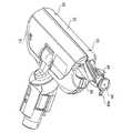
次に、吸込具5の構成について説明する。吸込具5は、図8に示すように、吸込口体18と接続部19とを備える。吸込具5は、管体4の前述した他端側に接続部19を介して連結される。図9に示すように、平面視において、吸込口体18の形状は矩形状を呈する。吸込口体18における清掃方向を、吸込口体18の短手方向と呼ぶ。平面視において、吸込口体18の短手方向に垂直な方向を吸込口体18の長手方向と呼ぶ。吸込口体18の長手方向の長さは、吸込口体18の短手方向の長さより長い。 Next, the configuration of thesuction tool 5 will be described. As shown in FIG. 8, thesuction tool 5 includes asuction port body 18 and aconnection portion 19. Thesuction tool 5 is connected to the other end side of thetubular body 4 via the connectingportion 19. As shown in FIG. 9, the shape of thesuction port body 18 is rectangular in a plan view. The cleaning direction of thesuction port body 18 is referred to as the lateral direction of thesuction port body 18. In a plan view, the direction perpendicular to the lateral direction of thesuction port body 18 is referred to as the longitudinal direction of thesuction port body 18. The length of thesuction port body 18 in the longitudinal direction is longer than the length of thesuction port body 18 in the lateral direction.

図10に示ように、吸込口体18は底部に2つの前車輪21と2つの後車輪22とを備える。前車輪21及び後車輪22は、前述した吸込口体18の長手方向の中心から左右対称な位置に配置される。前車輪21と後車輪22は、清掃時に被清掃面に転がり接触する。吸込口体18の底面には、吸込口23が形成されている。吸込口23は、下方を向いた開口である。 As shown in FIG. 10, thesuction port body 18 includes twofront wheels 21 and tworear wheels 22 at the bottom. Thefront wheels 21 and therear wheels 22 are arranged at positions symmetrical with respect to the center in the longitudinal direction of thesuction port body 18 described above. Thefront wheels 21 and therear wheels 22 roll into contact with the surface to be cleaned during cleaning. Asuction port 23 is formed on the bottom surface of thesuction port body 18. Thesuction port 23 is an opening facing downward.

吸込具5は被清掃面を清掃するためのものである。被清掃面は、例えば床面等の平面である。清掃時において吸込具5は、例えば、4つの前車輪21及び後車輪22のうちの3つ以上が被清掃面に接触する状態で配置される。この状態では、吸込具5を前後に移動させた際に前車輪21と後車輪22が被清掃面に転がり接触する。また、この状態では、吸込口体18の底面の大部分が被清掃面に平行に配置される。 Thesuction tool 5 is for cleaning the surface to be cleaned. The surface to be cleaned is a flat surface such as a floor surface. At the time of cleaning, thesuction tool 5 is arranged so that, for example, three or more of the fourfront wheels 21 and therear wheels 22 are in contact with the surface to be cleaned. In this state, when thesuction tool 5 is moved back and forth, thefront wheels 21 and therear wheels 22 roll into contact with the surface to be cleaned. Further, in this state, most of the bottom surface of thesuction port body 18 is arranged parallel to the surface to be cleaned.

吸込口体18は回転ブラシ40と図示しない回転ブラシモーターとを備える。吸込口体18の内部には、ブラシ室27が形成されている。ブラシ室27は、吸込口23と接続部19とに通じている。回転ブラシ40は、ブラシ室27の内部に吸込口23の上方から吸込口23を臨むようにして配置される。本体3から管体4を介して供給された電力により回転ブラシモーターを回転させ、その回転を動力伝達機構で伝達して回転ブラシ40を回転させる。回転ブラシ40が回転することで、被清掃面の塵埃が掻き上げられる。 Thesuction port 18 includes arotary brush 40 and a rotary brush motor (not shown). Abrush chamber 27 is formed inside thesuction port body 18. Thebrush chamber 27 communicates with thesuction port 23 and theconnection portion 19. Therotary brush 40 is arranged inside thebrush chamber 27 so that thesuction port 23 faces from above thesuction port 23. The rotary brush motor is rotated by the electric power supplied from themain body 3 via thetube body 4, and the rotation is transmitted by the power transmission mechanism to rotate therotary brush 40. By rotating therotary brush 40, dust on the surface to be cleaned is scraped up.

吸込口体18は、安全スイッチ26を備える。安全スイッチ26は、吸込口体18が被清掃面上にあるか否かを検知するためのものである。安全スイッチ26は、ホイール26aと図示しない弾性部材とを備える。弾性部材は例えばばねである。ホイール26aは、上下方向に移動可能に取り付けられている。ホイール26aは前車輪21及び後車輪22より上方にまで移動可能である。 Thesuction port body 18 includes asafety switch 26. Thesafety switch 26 is for detecting whether or not thesuction port body 18 is on the surface to be cleaned. Thesafety switch 26 includes a wheel 26a and an elastic member (not shown). The elastic member is, for example, a spring. The wheel 26a is attached so as to be movable in the vertical direction. The wheel 26a can move above thefront wheel 21 and therear wheel 22.

吸込口体18が被清掃面から離れると、弾性部材によりホイール26aは前車輪21及び後車輪22よりも下方に突出する。この状態では、安全スイッチ26は、吸込口体18が被清掃面上にないことを検知する。吸込口体18が被清掃面上にないことを安全スイッチ26が検知している場合、回転ブラシ40は回転しない。吸込口体18が被清掃面上にあると、被清掃面によりホイール26aは前車輪21及び後車輪22と同等な位置まで押し込まれる。この状態では、安全スイッチ26は、吸込口体18が被清掃面上にあることを検知する。吸込口体18が被清掃面上にあることを安全スイッチ26が検知している場合、回転ブラシ40は回転する。 When thesuction port body 18 is separated from the surface to be cleaned, the elastic member causes the wheel 26a to project downward from thefront wheel 21 and therear wheel 22. In this state, thesafety switch 26 detects that thesuction port body 18 is not on the surface to be cleaned. When thesafety switch 26 detects that thesuction port body 18 is not on the surface to be cleaned, the rotatingbrush 40 does not rotate. When thesuction port body 18 is on the surface to be cleaned, the surface to be cleaned pushes the wheel 26a to a position equivalent to that of thefront wheel 21 and therear wheel 22. In this state, thesafety switch 26 detects that thesuction port body 18 is on the surface to be cleaned. When thesafety switch 26 detects that thesuction port body 18 is on the surface to be cleaned, the rotatingbrush 40 rotates.

図9に示すように、接続部19の一端は、吸込口体18の長手方向における中間部で、かつ、短手方向における一側に、関節構造を介して取り付けられる。接続部19の他端側は、管体4の前述した他端側が着脱可能に接続される。 As shown in FIG. 9, one end of the connectingportion 19 is attached to the middle portion in the longitudinal direction of thesuction port body 18 and to one side in the lateral direction via the joint structure. The other end side of the connectingportion 19 is detachably connected to the other end side of thepipe body 4 described above.

図8及び図11に示すように、接続部19における前述の他端側には、第2のラッチ部24と第2の端子部25とが設けられている。第2のラッチ部24は、管体4と接続部19の結合状態を保持するとともに、この結合を使用者の操作により容易に解除できるようにするものである。 As shown in FIGS. 8 and 11, asecond latch portion 24 and a secondterminal portion 25 are provided on the other end side of theconnection portion 19 described above. Thesecond latch portion 24 maintains the coupled state between thetubular body 4 and the connectingportion 19, and allows the coupling to be easily released by the operation of the user.

第2のラッチ部24は、第2のラッチ24aと第2のカバーラッチ24bとを備える。接続部19の前述の他端側を管体4の前述の他端側に差し込むと、第2のラッチ24aが管体4の第1の係合部11bに掛かり、接続部19と管体4との結合状態が保持される。使用者が第2のラッチ24aを押すと、接続部19と管体4との結合状態が解除される。接続部19と管体4との結合が解除された状態で、吸込具5を管体4から離すように移動させると、管体4から吸込具5を取り外すことができる。 Thesecond latch portion 24 includes asecond latch 24a and asecond cover latch 24b. When the other end side of the connectingportion 19 is inserted into the other end side of thetubular body 4, thesecond latch 24a is hooked on the first engagingportion 11b of thetubular body 4, and the connectingportion 19 and thetubular body 4 The state of connection with is maintained. When the user pushes thesecond latch 24a, the coupling state between the connectingportion 19 and thetube body 4 is released. When thesuction tool 5 is moved away from thepipe body 4 in a state where theconnection portion 19 and thepipe body 4 are released, thesuction tool 5 can be removed from thepipe body 4.

第2のラッチ24aは、管体4でなく吸込具5側に設けられている。このようにすることで、使用者が一方の手で本体3のハンドル15又は管体4を持ったまま、他方の手で第2のラッチ24aを押しながら、管体4から吸込具5を取り外すことができる。 Thesecond latch 24a is provided not on thepipe body 4 but on thesuction tool 5 side. By doing so, the user removes thesuction tool 5 from thetube 4 while holding thehandle 15 or thetube 4 of themain body 3 with one hand and pressing thesecond latch 24a with the other hand. be able to.

第2の端子部25は、本体3と吸込具5とを通電させるための中継部品である。第2の端子部25は、図示しないリード線と接続されている。このリード線は、回転ブラシモーター及び安全スイッチ26と接続されている。 Thesecond terminal portion 25 is a relay component for energizing themain body 3 and thesuction tool 5. Thesecond terminal portion 25 is connected to a lead wire (not shown). This lead wire is connected to the rotary brush motor and thesafety switch 26.

接続部19の前述した関節構造は、相互に平行でない複数の回転軸を有し、複数の回転軸の中心にしてそれぞれの方向に独立して回転可能である。接続部19の関節構造は、例えば、図8及び図11に黒丸(●)で示す第1の回転軸Xと、一点鎖線で示す第2の回転軸Yとを有する。第1の回転軸Xは、側面視において吸込口体18の長手方向に平行な回転軸である。第2の回転軸Yは、側面視において水平方向に対して傾斜し、かつ上面視において短手方向に平行な回転軸である。第1の回転軸Xと第2の回転軸Yとは、ねじれの位置の関係にある。 The above-mentioned joint structure of the connectingportion 19 has a plurality of rotation axes that are not parallel to each other, and can rotate independently in each direction with the center of the plurality of rotation axes. The joint structure of the connectingportion 19 has, for example, a first rotation axis X indicated by a black circle (●) in FIGS. 8 and 11 and a second rotation axis Y indicated by an alternate long and short dash line. The first rotation axis X is a rotation axis parallel to the longitudinal direction of thesuction port body 18 in a side view. The second rotation axis Y is a rotation axis that is inclined with respect to the horizontal direction in the side view and parallel to the lateral direction in the top view. The first rotation axis X and the second rotation axis Y are in a twisted position relationship.

接続部19が第1の回転軸X及び第2の回転軸Yを中心として回転しても、吸込口23の開口方向は維持される。つまり、接続部19と連結されている管体4は、吸込口23の開口方向を維持した状態で、吸込口体18に対して、予め設定された角度範囲で傾けることが可能である。このようにして、接続部19は、吸込具5の底面と管体4の長手軸とがなす角度が予め設定された角度範囲内で変更可能に吸込具5と管体4とを連結する。 Even if the connectingportion 19 rotates about the first rotation axis X and the second rotation axis Y, the opening direction of thesuction port 23 is maintained. That is, thetubular body 4 connected to the connectingportion 19 can be tilted with respect to thesuction port body 18 within a preset angle range while maintaining the opening direction of thesuction port 23. In this way, the connectingportion 19 connects thesuction tool 5 and thepipe body 4 so that the angle formed by the bottom surface of thesuction tool 5 and the longitudinal axis of thepipe body 4 can be changed within a preset angle range.

図12に示すように、第1の回転軸Xを中心とする吸込口体18に対する接続部19の回転角度を第1の角度αとする。吸込具5の底面に平行で、かつ、吸込口体18から見て接続部19が配置される方向を第1の角度α=0°とした場合、第1の角度αは、例えば0°〜90°の範囲をとり得る。さらに好ましくは、第1の角度αは0°〜92°の範囲をとり得るようにするとよい。したがって、前述の角度範囲には、吸込具5の底面と管体4の長手軸とが平行となる角度が含まれる。また、前述の角度範囲には、吸込具5の底面と管体4の長手軸とが直角となる角度も含まれる。なお、図11は第1の角度α=0°、図12は第1の角度α=92°の状態である。 As shown in FIG. 12, the rotation angle of the connectingportion 19 with respect to thesuction port body 18 centered on the first rotation axis X is defined as the first angle α. When the direction in which the connectingportion 19 is arranged when viewed from thesuction port body 18 is parallel to the bottom surface of thesuction tool 5 and the first angle α = 0 °, the first angle α is, for example, 0 ° to It can take a range of 90 °. More preferably, the first angle α may be in the range of 0 ° to 92 °. Therefore, the above-mentioned angle range includes an angle at which the bottom surface of thesuction tool 5 and the longitudinal axis of thepipe body 4 are parallel to each other. Further, the above-mentioned angle range also includes an angle at which the bottom surface of thesuction tool 5 and the longitudinal axis of thepipe body 4 are at right angles. Note that FIG. 11 shows a state where the first angle α = 0 °, and FIG. 12 shows a state where the first angle α = 92 °.

また、図10に示すように、第2の回転軸Yを中心とする吸込口体18に対する接続部19の回転角度を第2の角度βとする。吸込口体18の長手方向に垂直な方向を第2の角度β=0°とした場合、第2の角度βは、例えば−90°〜+90°の範囲をとり得る。ただし、図10は、第2の回転軸Yとは直交しない方向から見たものであるため、この図10における見かけ上の第2の角度βは−90°〜+90°になっていない。第1の角度α=0°かつ第2の角度β=±90°のときには、接続部19の先端は吸込具5の底面より下方に位置する。 Further, as shown in FIG. 10, the rotation angle of the connectingportion 19 with respect to thesuction port body 18 centered on the second rotation axis Y is defined as the second angle β. Assuming that the direction perpendicular to the longitudinal direction of thesuction port body 18 is the second angle β = 0 °, the second angle β can be in the range of, for example, −90 ° to + 90 °. However, since FIG. 10 is viewed from a direction not orthogonal to the second rotation axis Y, the apparent second angle β in FIG. 10 is not −90 ° to + 90 °. When the first angle α = 0 ° and the second angle β = ± 90 °, the tip of the connectingportion 19 is located below the bottom surface of thesuction tool 5.

本体3、管体4及び吸込具5が一体になるように連結した際、第1の回転軸X及び第2の回転軸Yがいずれの角度においても、接続部19及び管体4は、前車輪21及び後車輪22の下端より上方に配置される。また、第2の角度βが0°の状態において、第1の回転軸Xがいずれの角度においても、本体3は前車輪21及び後車輪22の下端より上方に配置される。 When themain body 3, thepipe body 4 and thesuction tool 5 are connected so as to be integrated, the connectingportion 19 and thepipe body 4 are in front of each other regardless of the angle of the first rotation axis X and the second rotation axis Y. It is arranged above the lower ends of thewheels 21 and therear wheels 22. Further, in a state where the second angle β is 0 °, themain body 3 is arranged above the lower ends of thefront wheels 21 and therear wheels 22 regardless of the angle of the first rotation axis X.

この実施の形態に係る掃除機システム100は、図13及び図14に示すように、以上のように構成された電気掃除機1とスタンド2とを備える。スタンド2は、例えば、居室の床面に置かれる。電気掃除機1は、使用時にスタンド2から取り外される。スタンド2は、例えば充電台である。不使用時に、電気掃除機1をスタンド2に置くことで、電気掃除機1のバッテリ62を充電することができる。 As shown in FIGS. 13 and 14, thevacuum cleaner system 100 according to this embodiment includes the vacuum cleaner 1 and thestand 2 configured as described above. Thestand 2 is placed on the floor of the living room, for example. The vacuum cleaner 1 is removed from thestand 2 at the time of use. Thestand 2 is, for example, a charging stand. By placing the vacuum cleaner 1 on thestand 2 when not in use, thebattery 62 of the vacuum cleaner 1 can be charged.

スタンド2は、基台部210、支柱部220及び本体支持部230を備える。基台部210は、スタンド2の最も下方に配置される土台となる部分である。支柱部220は、基台部210の上面から鉛直上向きに直立して形成されている。本体支持部230は、支柱部220の中間部に固定されている。 Thestand 2 includes abase portion 210, asupport portion 220, and a mainbody support portion 230. Thebase portion 210 is a portion serving as a base arranged at the lowermost position of thestand 2. Thestrut portion 220 is formed upright vertically upward from the upper surface of thebase portion 210. The mainbody support portion 230 is fixed to the intermediate portion of thestrut portion 220.

電気掃除機1をスタンド2に載置する際、管体4及び接続管部63から見て、吸込具5の前端側及び集塵部17が配置された側が、スタンド2の支柱部220の方へと向けられる。すなわち、スタンド2は、電気掃除機1の本体3を、吸込具5の前端側から支持する。使用者は、掃除が終了した後に、そのまま、吸込具5の前側へと電気掃除機1を移動させながら、スタンド2に電気掃除機1を置くことができる。なお、吸込具5は、電気掃除機1がスタンド2に取り付けられる際、スタンド2の基台部210に支えられる。 When the vacuum cleaner 1 is placed on thestand 2, the front end side of thesuction tool 5 and the side on which thedust collecting portion 17 is arranged are thecolumns 220 of thestand 2 when viewed from thepipe body 4 and the connectingpipe portion 63. Directed to. That is, thestand 2 supports themain body 3 of the vacuum cleaner 1 from the front end side of thesuction tool 5. After the cleaning is completed, the user can place the vacuum cleaner 1 on thestand 2 while moving the vacuum cleaner 1 to the front side of thesuction tool 5 as it is. Thesuction tool 5 is supported by thebase portion 210 of thestand 2 when the vacuum cleaner 1 is attached to thestand 2.

次に、図15から図21も参照しながら、この実施の形態に係る吸込具5の構成について、さらに説明する。吸込具5の回転ブラシ40は、吸込口体18のブラシ室27の内側に回転軸を中心に回転可能に設けられている。回転ブラシ40の回転軸は、吸込口体の長手方向に平行である。 Next, the configuration of thesuction tool 5 according to this embodiment will be further described with reference to FIGS. 15 to 21. Therotary brush 40 of thesuction tool 5 is provided inside thebrush chamber 27 of thesuction port body 18 so as to be rotatable about a rotation axis. The rotation axis of therotation brush 40 is parallel to the longitudinal direction of the suction port body.

また、回転ブラシ40は、吸込口体18に対して着脱可能である。回転ブラシ40は、吸込口体18に取り付けられた状態で、ブラシ室27の内側に配置される。吸込口体18の側面には、開口54が形成されている。開口54は、ブラシ室27の内側と通じている。開口54から回転ブラシ40をブラシ室27の外側に引き出すことで、回転ブラシ40を吸込口体18から取り外すことができる。逆に、開口54から回転ブラシ40をブラシ室27の内側に差し込むことで、回転ブラシ40を吸込口体18に取り付けることができる。このような回転ブラシ40の取り付け/取り外しにおいて、回転ブラシ40は、前述の回転軸と平行に移動する。 Further, therotary brush 40 is removable from thesuction port body 18. Therotary brush 40 is arranged inside thebrush chamber 27 in a state of being attached to thesuction port body 18. Anopening 54 is formed on the side surface of thesuction port body 18. Theopening 54 communicates with the inside of thebrush chamber 27. By pulling therotary brush 40 out of thebrush chamber 27 from theopening 54, therotary brush 40 can be removed from thesuction port body 18. On the contrary, by inserting the rotatingbrush 40 into thebrush chamber 27 through theopening 54, the rotatingbrush 40 can be attached to thesuction port body 18. In such attachment / detachment of the rotatingbrush 40, the rotatingbrush 40 moves in parallel with the above-mentioned rotation axis.

図15から図17に示すように、回転ブラシ40は、清掃体41及び清掃体保持部42を備えている。清掃体41は、被清掃面上の塵埃を掻き取るためのものである。清掃体41は、例えば、ゴム等の弾性を有する素材からなるブレード、繊維質のブラシ毛等である。清掃体保持部42は円筒形の部材である。清掃体保持部42の外周部に、複数の清掃体41が螺旋状に突出して取り付けられている。清掃体保持部42の円筒形の中心軸は、回転ブラシ40の前述した回転軸に沿っている。 As shown in FIGS. 15 to 17, the rotatingbrush 40 includes a cleaningbody 41 and a cleaningbody holding portion 42. The cleaningbody 41 is for scraping dust on the surface to be cleaned. The cleaningbody 41 is, for example, a blade made of an elastic material such as rubber, a fibrous brush bristles, or the like. The cleaningbody holding portion 42 is a cylindrical member. A plurality of cleaningbodies 41 are spirally projected and attached to the outer peripheral portion of the cleaningbody holding portion 42. The cylindrical central axis of the cleaningbody holding portion 42 is along the above-mentioned rotating axis of the rotatingbrush 40.

前述したように、回転ブラシ40の回転は回転ブラシモーターにより駆動される。すなわち、この実施の形態の回転ブラシモーターは、回転ブラシ40を回転駆動するための動力を生成する駆動部である。駆動部により生成された動力は、動力伝達機構部30により回転ブラシ40に伝達される。 As described above, the rotation of therotary brush 40 is driven by the rotary brush motor. That is, the rotary brush motor of this embodiment is a drive unit that generates power for rotationally driving therotary brush 40. The power generated by the drive unit is transmitted to therotary brush 40 by the powertransmission mechanism unit 30.

図15に示すように、動力伝達機構部30は、ギア31及び連結凸部33を有している。ギア31及び連結凸部33は、同一のシャフト35に固定され、一体となって回転する。シャフト35は、吸込口体18側に設けられた支持部32により回転可能に支持されている。 As shown in FIG. 15, the powertransmission mechanism unit 30 has agear 31 and a connectingconvex portion 33. Thegear 31 and the connectingconvex portion 33 are fixed to thesame shaft 35 and rotate integrally. Theshaft 35 is rotatably supported by asupport portion 32 provided on thesuction port body 18 side.

連結凸部33は、ブラシ室27内に突出している。清掃体保持部42の開口54とは反対側の端部には、連結凹部43が形成されている。回転ブラシ40がブラシ室27内に取り付けられた状態では、連結凸部33が連結凹部43の内側に配置され、連結凸部33と連結凹部43とが係合する。連結凸部33と連結凹部43とが係合した状態では、連結凸部33と連結凹部43とが一体となって回転する。 The connectingconvex portion 33 projects into thebrush chamber 27. A connectingrecess 43 is formed at the end of the cleaningbody holding portion 42 opposite to theopening 54. In the state where the rotatingbrush 40 is mounted in thebrush chamber 27, the connectingconvex portion 33 is arranged inside the connectingconcave portion 43, and the connectingconvex portion 33 and the connectingconcave portion 43 engage with each other. In a state where the connectingconvex portion 33 and the connectingconcave portion 43 are engaged, the connectingconvex portion 33 and the connectingconcave portion 43 rotate integrally.

駆動部である回転ブラシモーターの駆動軸の回転は、まず、ギア31に伝達される。ギア31の回転は、前述のシャフトを介して連結凸部33の回転となる。そして、この連結凸部33の回転は、連結凹部43を介して回転ブラシ40に伝達される。以上のように構成された連結凸部33及び連結凹部43は、前述した駆動部の動力をブラシ室27の内側に取り付けられた回転ブラシ40に伝達する連結部である。 The rotation of the drive shaft of the rotary brush motor, which is the drive unit, is first transmitted to thegear 31. The rotation of thegear 31 is the rotation of the connectingconvex portion 33 via the shaft described above. Then, the rotation of the connectingconvex portion 33 is transmitted to the rotatingbrush 40 via the connectingconcave portion 43. The connectingconvex portion 33 and the connectingconcave portion 43 configured as described above are connecting portions that transmit the power of the driving portion described above to the rotatingbrush 40 attached to the inside of thebrush chamber 27.

図15及び図16に示すように、回転ブラシ40を取り付けた状態で、この連結部の一部は、吸込口23に臨む位置に配置される。吸込口体18は、カバー34を備えている。カバー34は、連結部よりも吸込口23側に配置されている。そして、カバー34は、連結部の吸込口23に臨む部分の少なくとも一部を覆っている。このようなカバー34を備えることで、吸込口23側から連結部内に塵埃が侵入することを抑制できる。 As shown in FIGS. 15 and 16, with the rotatingbrush 40 attached, a part of the connecting portion is arranged at a position facing thesuction port 23. Thesuction port body 18 includes acover 34. Thecover 34 is arranged on thesuction port 23 side of the connecting portion. Thecover 34 covers at least a part of the portion of the connecting portion facing thesuction port 23. By providing such acover 34, it is possible to prevent dust from entering the connecting portion from thesuction port 23 side.

また、連結凸部33の吸込口23に臨む部分の少なくとも一部には、テーパ部33aが設けられている。テーパ部33aは、回転ブラシ40側にいくに従って細くなるテーパ状を呈する。このようなテーパ部33aを備えることで、回転ブラシ40に巻き付いた毛髪、糸くず等が、連結凸部33からさらに動力伝達機構部30の奥へと移動してしまうことを抑制できる。 Further, a taperedportion 33a is provided at least a part of the portion of the connectingconvex portion 33 facing thesuction port 23. The taperedportion 33a has a tapered shape that becomes thinner toward the rotatingbrush 40 side. By providing such atapered portion 33a, it is possible to prevent hair, lint, etc. wound around the rotatingbrush 40 from moving further from the connectingconvex portion 33 to the depth of the powertransmission mechanism portion 30.

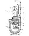
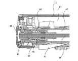
回転ブラシ40は軸部材を備えている。軸部材は、清掃体保持部42を吸込口体18に対して前述の回転軸を中心に回転可能に支持する部材である。図17及び図18に示すように、軸部材は、第1の軸部材44、第2の軸部材45、第3の軸部材46及び第4の軸部材47を有する。第1の軸部材44は、細長い棒状の部材である。第1の軸部材44は、清掃体保持部42の円筒形の中心軸に沿って設けられる。第2の軸部材45、第3の軸部材46及び第4の軸部材47は、第1の軸部材44の開口54側の端部寄りに設けられている。 Therotary brush 40 includes a shaft member. The shaft member is a member that rotatably supports the cleaningbody holding portion 42 with respect to thesuction port body 18 around the above-mentioned rotating shaft. As shown in FIGS. 17 and 18, the shaft member has afirst shaft member 44, asecond shaft member 45, athird shaft member 46, and afourth shaft member 47. Thefirst shaft member 44 is an elongated rod-shaped member. Thefirst shaft member 44 is provided along the cylindrical central axis of the cleaningbody holding portion 42. Thesecond shaft member 45, thethird shaft member 46, and thefourth shaft member 47 are provided near the end of thefirst shaft member 44 on theopening 54 side.

第2の軸部材45は、第3の軸部材46と回転方向に対し固定されている。第3の軸部材46は、第2の軸部材45よりも開口54側で、かつ、第2の軸部材45の外側に配置されている。そして、第4の軸部材47は、第2の軸部材45及び第3の軸部材46の両方を覆うようにして第1の軸部材44に固定されている。第3の軸部材46は、第1の軸部材44に固定されていない。このため、第3の軸部材46は、第1の軸部材44、第2の軸部材45及び第4の軸部材47に対して移動可能である。第3の軸部材46は、第1の軸部材44に対し前述の回転軸に沿って移動できる。したがって、軸部材は、前述の回転軸に平行な方向に伸縮可能である。 Thesecond shaft member 45 is fixed to thethird shaft member 46 in the rotational direction. Thethird shaft member 46 is arranged closer to theopening 54 than thesecond shaft member 45 and outside thesecond shaft member 45. Then, thefourth shaft member 47 is fixed to thefirst shaft member 44 so as to cover both thesecond shaft member 45 and thethird shaft member 46. Thethird shaft member 46 is not fixed to thefirst shaft member 44. Therefore, thethird shaft member 46 is movable with respect to thefirst shaft member 44, thesecond shaft member 45, and thefourth shaft member 47. Thethird shaft member 46 can move with respect to thefirst shaft member 44 along the above-mentioned rotation axis. Therefore, the shaft member can be expanded and contracted in the direction parallel to the above-mentioned rotation axis.

回転ブラシ40は、把持部48を備えている。把持部48は、吸込口体18に対して回転ブラシ40を着脱する時に使用者が把持するための部位である。把持部48は、軸部材の開口54側の端部に設けられている。より詳しくは、把持部48は、第3の軸部材46に固定されている。このため、把持部48は、第3の軸部材46と一体となって、第1の軸部材44、第2の軸部材45及び第4の軸部材47に対して移動可能である。 Therotary brush 40 includes agrip portion 48. Thegrip portion 48 is a portion for the user to grip when attaching / detaching therotary brush 40 to / from thesuction port body 18. Thegrip portion 48 is provided at the end portion of the shaft member on theopening 54 side. More specifically, thegrip portion 48 is fixed to thethird shaft member 46. Therefore, thegrip portion 48 can move integrally with thethird shaft member 46 with respect to thefirst shaft member 44, thesecond shaft member 45, and thefourth shaft member 47.

回転ブラシ40は、弾性体49を備えている。弾性体49は、第2の軸部材45と第3の軸部材46との間に配置されている。弾性体49は、例えば押しばねである。弾性体49は、第2の軸部材45と第3の軸部材46との間隔を広げる方向に力を掛けている。したがって、回転ブラシ40が吸込口体18に取り付けられた状態で、第3の軸部材46及び把持部48は、弾性体49により開口54からさらにブラシ室27の外側へと押されている。つまり、弾性体49は、把持部48を前述の回転軸に沿ってブラシ室27の外側に押し出している。この弾性体49の弾性力により、回転ブラシ40に外力が作用していない状態では軸部材は伸長する。また、第4の軸部材47は、弾性体49の外側から覆っている。すなわち、弾性体49は、軸部材の内側に設けられている。 Therotary brush 40 includes anelastic body 49. Theelastic body 49 is arranged between thesecond shaft member 45 and thethird shaft member 46. Theelastic body 49 is, for example, a push spring. Theelastic body 49 applies a force in a direction of widening the distance between thesecond shaft member 45 and thethird shaft member 46. Therefore, with therotary brush 40 attached to thesuction port body 18, thethird shaft member 46 and thegrip portion 48 are further pushed from theopening 54 to the outside of thebrush chamber 27 by theelastic body 49. That is, theelastic body 49 pushes thegrip portion 48 to the outside of thebrush chamber 27 along the above-mentioned rotation axis. Due to the elastic force of theelastic body 49, the shaft member extends in a state where no external force is applied to the rotatingbrush 40. Further, thefourth shaft member 47 covers from the outside of theelastic body 49. That is, theelastic body 49 is provided inside the shaft member.

図8及び図19に示すように、吸込口体18の開口54が形成された側面には、収納部55が設けられている。収納部55は、吸込口体18の側面が凹んで形成された部位である。把持部48には、レバー48aが設けられている。レバー48aは、把持部48の側面から突出している。回転ブラシ40が吸込口体18に取り付けられた状態で、把持部48は開口54からブラシ室27の外側に出ている。この状態において、把持部48のレバー48aは、収納部55の内側に配置される。 As shown in FIGS. 8 and 19, astorage portion 55 is provided on the side surface of thesuction port body 18 where theopening 54 is formed. Thestorage portion 55 is a portion formed by denting the side surface of thesuction port body 18. Thegrip portion 48 is provided with alever 48a. Thelever 48a protrudes from the side surface of thegrip portion 48. With therotary brush 40 attached to thesuction port body 18, thegrip portion 48 protrudes from theopening 54 to the outside of thebrush chamber 27. In this state, thelever 48a of thegrip portion 48 is arranged inside thestorage portion 55.

図19に示すように、収納部55内には、取付け位置55aと取外し位置55bとが設けられている。回転ブラシ40が吸込口体18に取り付けられているとき、把持部48及びレバー48aは、軸部材を中心に回転可能である。収納部55内にレバー48aがある状態において把持部48及びレバー48aが回転することで、レバー48aは、取付け位置55aと取外し位置55bとの間で移動する。 As shown in FIG. 19, a mountingposition 55a and a removingposition 55b are provided in thestorage portion 55. When therotary brush 40 is attached to thesuction port body 18, thegrip portion 48 and thelever 48a are rotatable about the shaft member. When thegrip portion 48 and thelever 48a rotate while thelever 48a is in thestorage portion 55, thelever 48a moves between theattachment position 55a and theremoval position 55b.

取付け位置55aと取外し位置55bとの間には、突出部56が設けられている。この突出部56によりレバー48aが取付け位置55aと取外し位置55bとの間で自由に移動することが規制されている。そして、レバー48aに力を加えて回転させることで、レバー48aが突出部56を乗り越えてレバー48aが取付け位置55aと取外し位置55bとの間で移動させることができる。 Aprotrusion 56 is provided between the mountingposition 55a and the removingposition 55b. Theprotrusion 56 regulates thelever 48a from freely moving between theattachment position 55a and theremoval position 55b. Then, by applying a force to thelever 48a to rotate it, thelever 48a can move over theprotrusion 56 and thelever 48a can be moved between theattachment position 55a and theremoval position 55b.

回転ブラシ40を吸込口体18に取り付ける際には、開口54から回転ブラシ40をブラシ室27の内側に差し込み、さらに、弾性体49の弾性力に抗して把持部48を押し込む。そして、把持部48を押し込んだまま、レバー48aを取外し位置55bから取付け位置55aにまで回転させる。すると、把持部48及び第3の軸部材46が、吸込口体18の壁部57に係合し、把持部48が押し込まれた状態で保持される。こうして、図15及び図17に示すように、回転ブラシ40が吸込口体18に取り付けされた状態で固定される。 When therotary brush 40 is attached to thesuction port body 18, therotary brush 40 is inserted into the inside of thebrush chamber 27 through theopening 54, and thegrip portion 48 is further pushed against the elastic force of theelastic body 49. Then, while pushing thegrip portion 48, thelever 48a is removed and rotated from theposition 55b to the mountingposition 55a. Then, thegrip portion 48 and thethird shaft member 46 are engaged with thewall portion 57 of thesuction port body 18, and thegrip portion 48 is held in a pushed state. In this way, as shown in FIGS. 15 and 17, the rotatingbrush 40 is fixed in a state of being attached to thesuction port body 18.

一方、回転ブラシ40を吸込口体18から取り外す際には、レバー48aを取付け位置55aから取外し位置55bにまで回転させる。すると、図18に示すように、把持部48及び第3の軸部材46と壁部57との係合が外れ、弾性体49の弾性力により、回転ブラシ40の軸部材が伸びて把持部48及び第3の軸部材46が開口54よりブラシ室27のさらに外側に押し出される。この状態では、把持部48は、吸込口体18のケース外郭58よりも外側に突出する。このため、使用者は容易に把持部48を持って回転ブラシ40を引き出すことができる。なお、図20に示すのは、このような回転ブラシ40の取り付け/取り外しの途中の状態である。 On the other hand, when therotary brush 40 is removed from thesuction port body 18, thelever 48a is rotated from theattachment position 55a to theremoval position 55b. Then, as shown in FIG. 18, thegrip portion 48 and thethird shaft member 46 are disengaged from thewall portion 57, and the shaft member of therotary brush 40 is extended by the elastic force of theelastic body 49 to extend thegrip portion 48. And thethird shaft member 46 is pushed out from theopening 54 to the outside of thebrush chamber 27. In this state, thegrip portion 48 projects outward from the caseouter shell 58 of thesuction port body 18. Therefore, the user can easily pull out therotary brush 40 by holding thegrip portion 48. Note that FIG. 20 shows a state in which the rotatingbrush 40 is being attached / detached.

このように、この実施の形態の吸込具5においては、着脱時に使用者が把持するための把持部48が、回転ブラシ40の軸部材の開口54側の端部に設けられている。そして、把持部48を回転軸に沿ってブラシ室27の外側に押し出す弾性体49が、回転ブラシ40の軸部材の内側に設けられている。このため、把持部48は使用者が持つのに必要なだけの大きさであればよいため、回転ブラシ40の全長に対し把持部48が占める割合が大きくなることを抑制できる。そして、回転ブラシ40を取り外す際には、軸部材内の弾性体49により把持部48を吸込口体18のケース外郭58よりも外側に突出させることが可能である。したがって、清掃能力の低下及び回転ブラシ40の大型化のいずれも招くことなく、回転ブラシ40の着脱が容易である。 As described above, in thesuction tool 5 of this embodiment, thegrip portion 48 for the user to grip at the time of attachment / detachment is provided at the end portion of the shaft member of therotary brush 40 on theopening 54 side. Anelastic body 49 that pushes thegrip portion 48 to the outside of thebrush chamber 27 along the rotation axis is provided inside the shaft member of therotation brush 40. Therefore, since thegrip portion 48 may be of a size necessary for the user to hold, it is possible to prevent thegrip portion 48 from becoming a large proportion of the total length of the rotatingbrush 40. Then, when therotary brush 40 is removed, thegrip portion 48 can be projected to the outside of the caseouter shell 58 of thesuction port body 18 by theelastic body 49 in the shaft member. Therefore, the rotatingbrush 40 can be easily attached and detached without causing a decrease in cleaning ability and an increase in the size of the rotatingbrush 40.

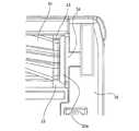
図10から図12に示すように、吸込口体18の前端面の下端部には、斜面部51が形成されている。換言すれば、斜面部51は、吸込口体18の底面における吸込口23よりも前側に設けられている。斜面部51は、左右方向において吸込口23と同範囲に配置されている。このような斜面部51を備えることで被清掃面上の例えば米粒等のごみを吸込口体18の前端で弾くことなく、吸込口23で吸い込むことが出来る。 As shown in FIGS. 10 to 12, aslope portion 51 is formed at the lower end of the front end surface of thesuction port body 18. In other words, theslope portion 51 is provided on the bottom surface of thesuction port body 18 on the front side of thesuction port 23. Theslope portion 51 is arranged in the same range as thesuction port 23 in the left-right direction. By providing such aslope portion 51, dust such as rice grains on the surface to be cleaned can be sucked in by thesuction port 23 without being repelled by the front end of thesuction port body 18.

図8、図9等に示すように、吸込口体18の前端面には、バッファ部52が取り付けられている。バッファ部52は、例えばシリコン樹脂等の弾性変形可能な軟質材からなる。バッファ部52は、吸込口体18が部屋の壁等に当たる衝撃を緩和し、傷つきを防止する役割を持つ。バッファ部52は、斜面部51を前側から覆っている。すなわち、バッファ部52は、吸込口体18の前端面に斜面部51を前側から覆って取り付けられた軟質材である。 As shown in FIGS. 8 and 9, abuffer portion 52 is attached to the front end surface of thesuction port body 18. Thebuffer portion 52 is made of an elastically deformable soft material such as silicon resin. Thebuffer portion 52 has a role of alleviating the impact of thesuction port body 18 hitting the wall or the like of the room and preventing damage. Thebuffer portion 52 covers theslope portion 51 from the front side. That is, thebuffer portion 52 is a soft material attached to the front end surface of thesuction port body 18 by covering theslope portion 51 from the front side.

図19及び図20に示すように、軟質材であるバッファ部52には、2つのスリット53が形成されている。これらのスリット53は、バッファ部52の下端にまで達している。また、図10及び図21に示すように、これらのスリット53は、斜面部51の左右両端それぞれの位置に配置されている。このような斜面部51と2つのスリット53とを備えることで2つのスリット53の間におけるバッファ部52の下側の部分が、被清掃面に対する吸込口体18の動きに応じて変形しやすくなる。このため、被清掃面に対する吸込口体18の動きにバッファ部52下端が追従し、特に絨毯等の摩擦が大きい被清掃面での操作が楽になる。 As shown in FIGS. 19 and 20, twoslits 53 are formed in thebuffer portion 52 which is a soft material. Theseslits 53 reach the lower end of thebuffer portion 52. Further, as shown in FIGS. 10 and 21, theseslits 53 are arranged at the left and right ends of theslope portion 51, respectively. By providing such aslope portion 51 and twoslits 53, the lower portion of thebuffer portion 52 between the twoslits 53 is easily deformed according to the movement of thesuction port body 18 with respect to the surface to be cleaned. .. Therefore, the lower end of thebuffer portion 52 follows the movement of thesuction port body 18 with respect to the surface to be cleaned, which facilitates the operation on the surface to be cleaned, such as a carpet, which has a large friction.

図13に示すように、スタンド2の基台部210にはスタンド側斜面部211が設けられている。吸込具5をスタンド2の基台部210に載せる際、スタンド側斜面部211に吸込口体18の斜面部51が当たり、少ない力で円滑に吸込口体18を基台部210に載せることが可能である。この際、2つのスリット53の間のバッファ部52が、斜面部51に沿うように変形するため、基台部210上への吸込口体18の移動を、さらに円滑にできる。 As shown in FIG. 13, thebase portion 210 of thestand 2 is provided with a stand-side slope portion 211. When thesuction tool 5 is placed on thebase portion 210 of thestand 2, theslope portion 51 of thesuction port body 18 hits theslope portion 211 on the stand side, and thesuction port body 18 can be smoothly placed on thebase portion 210 with a small force. It is possible. At this time, since thebuffer portion 52 between the twoslits 53 is deformed along theslope portion 51, thesuction port body 18 can be further smoothly moved onto thebase portion 210.

なお、以上の説明においては長手軸及び中心軸という語を用いている。これらの語について、中心軸とは、必ずしもその外形を完全な円形に限るものではなく、外形に例えば係合や嵌合のための凹凸があってもよい。また、中心軸は、幅方向の中心又は奥行方向の中心の軸も含み得る。すなわち、中心軸は、幅方向の中心又は奥行方向の中心にある長手軸とも捉えられる。要するに、中心軸とは、長手軸を有する物体のおおよその中心の軸をさす。 In the above description, the terms longitudinal axis and central axis are used. For these terms, the central axis does not necessarily limit its outer shape to a perfect circle, and the outer shape may have irregularities for engagement or fitting, for example. The central axis may also include a center axis in the width direction or a center axis in the depth direction. That is, the central axis can also be regarded as a longitudinal axis located at the center in the width direction or the center in the depth direction. In short, the central axis refers to the approximate central axis of an object having a longitudinal axis.

1 電気掃除機
2 スタンド
3 本体
4 管体
5 吸込具
11 パイプ部
11a パイプ
11b 第1の係合部
12 パイプカバー部
13 第1のラッチ部
13a 第1のラッチ
13b 第1のカバーラッチ
14 第1の端子部
15 ハンドル
16 外郭部
17 集塵部
18 吸込口体
19 接続部
21 前車輪
22 後車輪
23 吸込口
24 第2のラッチ部
24a 第2のラッチ
24b 第2のカバーラッチ
25 第2の端子部
26 安全スイッチ
26a ホイール
27 ブラシ室
30 動力伝達機構部
31 ギア
32 支持部
33 連結凸部
33a テーパ部
34 カバー
35 シャフト
40 回転ブラシ
41 清掃体
42 清掃体保持部
43 連結凹部
44 第1の軸部材
45 第2の軸部材
46 第3の軸部材
47 第4の軸部材
48 把持部
48a レバー
49 弾性体
51 斜面部
52 バッファ部
53 スリット
54 開口
55 収納部
55a 取付け位置
55b 取外し位置
56 突出部
57 壁部
58 ケース外郭
61 ケース部
62 バッテリ
63 接続管部
64 排気部
65 操作部
66 電動送風機
67 制御部
68 接続口
69 集塵室
100 掃除機システム
210 基台部
211 スタンド側斜面部
220 支柱部
230 本体支持部
1Vacuum cleaner 2Stand 3Main body 4Pipe body 5Suction tool 11Pipepart 11a Pipe 11bFirst engaging part 12Pipe cover part 13First latch part 13aFirst latch 13bFirst cover latch 14First Terminal part 15Handle 16Outer part 17Dust collection part 18Suction port body 19Connection part 21Front wheel 22Rear wheel 23Suction port 24Second latch part 24aSecond latch 24bSecond cover latch 25Second terminal Part 26 Safetyswitch 26a Wheel 27Brush chamber 30 Powertransmission mechanism part 31Gear 32Support part 33 Connectingconvex part 33a Taperedpart 34Cover 35Shaft 40 Rotatingbrush 41Cleaning body 42 Cleaningbody holding part 43Connecting recess 44First shaft member 452nd shaft member 463rd shaft member 474th shaft member 48Grippart 48a Lever 49Elastic body 51Slope part 52Buffer part 53Slit 54Opening 55Storage part55a Mounting position55b Removing position 56Protruding part 57Wall Part 58 Caseouter shape 61Case part 62Battery 63Connection pipe part 64Exhaust part 65Operation part 66Electric blower 67Control part 68Connection port 69Dust collection room 100 Vacuumcleaner system 210Base part 211 Standside slope part 220Support part 230 Main body Support

Claims (6)

Translated fromJapanese
吸込口が形成された吸込口体と、
前記吸込口体の内部に前記吸込口と通じて形成されたブラシ室の内側に前記吸込口に臨んで設けられ、回転軸を中心に回転可能な回転ブラシと、を備え、
前記回転ブラシは、
前記回転軸と平行に移動して前記吸込口体の側面に形成された開口を通して前記ブラシ室の内側に着脱可能であるとともに、
外周部に清掃体が取り付けられた清掃体保持部と、
前記清掃体保持部を前記吸込口体に対して前記回転軸を中心に回転可能に支持する軸部材と、
前記軸部材の前記開口側の端部に設けられ、着脱時に使用者が把持するための把持部と、
前記軸部材の内側に設けられ、前記把持部を前記回転軸に沿って前記ブラシ室の外側に押し出す弾性体と、を備えた吸込具。
The suction port body with the suction port formed and
A rotating brush provided inside the suction port body and inside a brush chamber formed through the suction port so as to face the suction port and can rotate about a rotation axis is provided.
The rotating brush
It moves parallel to the rotation axis and can be attached to and detached from the inside of the brush chamber through an opening formed on the side surface of the suction port body.
A cleaning body holding part with a cleaning body attached to the outer circumference,
A shaft member that rotatably supports the cleaning body holding portion with respect to the suction port body about the rotation shaft, and
A grip portion provided at the end of the shaft member on the opening side and for the user to grip at the time of attachment / detachment.
A suction tool provided inside the shaft member and comprising an elastic body that pushes the grip portion to the outside of the brush chamber along the rotation axis.
前記軸部材は、前記回転軸に平行な方向に伸縮可能である請求項1に記載の吸込具。 The suction tool according to claim 1, wherein the shaft member can be expanded and contracted in a direction parallel to the rotation axis. 前記回転ブラシを回転駆動するための動力を生成する駆動部と、
前記駆動部の動力を前記ブラシ室の内側に取り付けられた前記回転ブラシに伝達する連結部と、
前記連結部の前記吸込口に臨む部分の少なくとも一部を覆うカバーと、をさらに備えた請求項1又は請求項2に記載の吸込具。
A drive unit that generates power for rotationally driving the rotary brush,
A connecting portion that transmits the power of the driving unit to the rotating brush mounted inside the brush chamber, and a connecting portion.
The suction tool according to claim 1 or 2, further comprising a cover that covers at least a part of the connecting portion facing the suction port.
前記連結部は、前記吸込口に臨む部分の少なくとも一部に設けられ、前記回転ブラシ側にいくに従って細くなるテーパ部を備えた請求項3に記載の吸込具。 The suction tool according to claim 3, wherein the connecting portion is provided at least a part of a portion facing the suction port, and has a tapered portion that becomes thinner toward the rotating brush side. 前記吸込口体の前端面の下端部に形成された斜面部をさらに備え、
前記斜面部は、左右方向において前記吸込口と同範囲に配置された請求項1から請求項4のいずれか一項に記載の吸込具。
A slope portion formed at the lower end of the front end surface of the suction port body is further provided.
The suction tool according to any one of claims 1 to 4, wherein the slope portion is arranged in the same range as the suction port in the left-right direction.
前記吸込口体の前記前端面に前記斜面部を前側から覆って取り付けられた軟質材をさらに備え、
前記軟質材には、前記軟質材の下端に達するスリットが前記斜面部の左右両端それぞれの位置に形成された請求項5に記載の吸込具。
A soft material attached to the front end surface of the suction port body by covering the slope portion from the front side is further provided.
The suction tool according to claim 5, wherein slits reaching the lower ends of the soft material are formed in the soft material at positions at both left and right ends of the slope portion.
JP2019118767A2019-06-262019-06-26 InhalerActiveJP7200848B2 (en)

Priority Applications (1)

Application NumberPriority DateFiling DateTitle
JP2019118767AJP7200848B2 (en)2019-06-262019-06-26 Inhaler

Applications Claiming Priority (1)

Application NumberPriority DateFiling DateTitle
JP2019118767AJP7200848B2 (en)2019-06-262019-06-26 Inhaler

Publications (2)

Publication NumberPublication Date
JP2021003357Atrue JP2021003357A (en)2021-01-14
JP7200848B2 JP7200848B2 (en)2023-01-10

Family

ID=74097171

Family Applications (1)

Application NumberTitlePriority DateFiling Date
JP2019118767AActiveJP7200848B2 (en)2019-06-262019-06-26 Inhaler

Country Status (1)

CountryLink
JP (1)JP7200848B2 (en)

Cited By (1)

* Cited by examiner, † Cited by third party
Publication numberPriority datePublication dateAssigneeTitle
CN113876238A (en)*2021-09-302022-01-04添可智能科技有限公司Cleaning device, rolling brush assembly and lifting handle

Citations (4)

* Cited by examiner, † Cited by third party
Publication numberPriority datePublication dateAssigneeTitle
JPS60101047U (en)*1983-12-131985-07-10松下電器産業株式会社 vacuum cleaner floor nozzle
JP2001087179A (en)*1999-09-242001-04-03Mitsubishi Electric Corp Suction port for vacuum cleaner
JP2015177977A (en)*2014-03-192015-10-08ダイソン・テクノロジー・リミテッド Vacuum cleaner head
JP2018140003A (en)*2017-02-282018-09-13シャープ株式会社 Vacuum cleaner bedding inlet body

Patent Citations (4)

* Cited by examiner, † Cited by third party
Publication numberPriority datePublication dateAssigneeTitle
JPS60101047U (en)*1983-12-131985-07-10松下電器産業株式会社 vacuum cleaner floor nozzle
JP2001087179A (en)*1999-09-242001-04-03Mitsubishi Electric Corp Suction port for vacuum cleaner
JP2015177977A (en)*2014-03-192015-10-08ダイソン・テクノロジー・リミテッド Vacuum cleaner head
JP2018140003A (en)*2017-02-282018-09-13シャープ株式会社 Vacuum cleaner bedding inlet body

Cited By (2)

* Cited by examiner, † Cited by third party
Publication numberPriority datePublication dateAssigneeTitle
CN113876238A (en)*2021-09-302022-01-04添可智能科技有限公司Cleaning device, rolling brush assembly and lifting handle
CN113876238B (en)*2021-09-302023-12-01添可智能科技有限公司Cleaning device, rolling brush assembly and handle

Also Published As

Publication numberPublication date
JP7200848B2 (en)2023-01-10

Similar Documents

PublicationPublication DateTitle
US20210038038A1 (en)Surface cleaning apparatus
EP3231344A1 (en)Suction body for an upright cleaner
KR101143659B1 (en)Convertible vacuum cleaner
JP2520732B2 (en) Vacuum cleaner suction body
KR20100057026A (en)Surface debris removal apparatus
US20060277713A1 (en)Vacuum turbo nozzle with movable visor
TWI689277B (en) Charging base of electric vacuum cleaner
JP2009504311A (en) Vacuum cleaner
JP6628511B2 (en) Electric cleaning equipment
CN113545702B (en) Sweeping tools and cordless vacuum cleaners
JP2021003357A (en)Suction tool
JP6202120B2 (en) Vacuum cleaner and vacuum cleaner
JP7013038B2 (en) Vacuum cleaner with bag
JP2005110714A (en) Electric vacuum cleaner
JP7035446B2 (en) Suction tool and vacuum cleaner
JP7020111B2 (en) Vacuum cleaner and vacuum cleaner system
JP2008161257A (en) Electric vacuum cleaner
KR101208559B1 (en)An upright type vacuum cleaner
JP2007252642A (en) Vacuum cleaner inlet and vacuum cleaner
JP7400858B2 (en) Cleaning tools, vacuum cleaners, and cordless vacuum cleaners
JP3390901B2 (en) Electric vacuum cleaner
JP6306303B2 (en) Electric vacuum cleaner
JP6763455B2 (en) Vacuum cleaner and vacuum cleaner
JP5868072B2 (en) Suction port and vacuum cleaner
JP3587027B2 (en) Electric vacuum cleaner

Legal Events

DateCodeTitleDescription
A621Written request for application examination

Free format text:JAPANESE INTERMEDIATE CODE: A621

Effective date:20210528

A977Report on retrieval

Free format text:JAPANESE INTERMEDIATE CODE: A971007

Effective date:20220425

A131Notification of reasons for refusal

Free format text:JAPANESE INTERMEDIATE CODE: A131

Effective date:20220510

A521Request for written amendment filed

Free format text:JAPANESE INTERMEDIATE CODE: A523

Effective date:20220707

TRDDDecision of grant or rejection written
A01Written decision to grant a patent or to grant a registration (utility model)

Free format text:JAPANESE INTERMEDIATE CODE: A01

Effective date:20221122

A61First payment of annual fees (during grant procedure)

Free format text:JAPANESE INTERMEDIATE CODE: A61

Effective date:20221205

R150Certificate of patent or registration of utility model

Ref document number:7200848

Country of ref document:JP

Free format text:JAPANESE INTERMEDIATE CODE: R150


[8]ページ先頭

©2009-2025 Movatter.jp