JP2021001833A - Position estimating device and method - Google Patents
Position estimating device and methodDownload PDFInfo
- Publication number
- JP2021001833A JP2021001833AJP2019116233AJP2019116233AJP2021001833AJP 2021001833 AJP2021001833 AJP 2021001833AJP 2019116233 AJP2019116233 AJP 2019116233AJP 2019116233 AJP2019116233 AJP 2019116233AJP 2021001833 AJP2021001833 AJP 2021001833A
- Authority
- JP
- Japan
- Prior art keywords
- estimated
- communication device
- distance
- wireless communication
- access point
- Prior art date
- Legal status (The legal status is an assumption and is not a legal conclusion. Google has not performed a legal analysis and makes no representation as to the accuracy of the status listed.)
- Pending
Links
- 238000000034methodMethods0.000titleclaimsdescription9
- 230000005540biological transmissionEffects0.000claimsdescription31
- 238000005259measurementMethods0.000claimsdescription6
- 238000010586diagramMethods0.000abstractdescription13
- 238000009795derivationMethods0.000description22
- 238000001514detection methodMethods0.000description6
Images


Classifications
- H—ELECTRICITY
- H04—ELECTRIC COMMUNICATION TECHNIQUE
- H04B—TRANSMISSION
- H04B17/00—Monitoring; Testing
- H04B17/20—Monitoring; Testing of receivers
- H04B17/27—Monitoring; Testing of receivers for locating or positioning the transmitter
- G—PHYSICS
- G01—MEASURING; TESTING
- G01S—RADIO DIRECTION-FINDING; RADIO NAVIGATION; DETERMINING DISTANCE OR VELOCITY BY USE OF RADIO WAVES; LOCATING OR PRESENCE-DETECTING BY USE OF THE REFLECTION OR RERADIATION OF RADIO WAVES; ANALOGOUS ARRANGEMENTS USING OTHER WAVES
- G01S11/00—Systems for determining distance or velocity not using reflection or reradiation
- G01S11/02—Systems for determining distance or velocity not using reflection or reradiation using radio waves
- G01S11/06—Systems for determining distance or velocity not using reflection or reradiation using radio waves using intensity measurements
- G—PHYSICS
- G01—MEASURING; TESTING
- G01S—RADIO DIRECTION-FINDING; RADIO NAVIGATION; DETERMINING DISTANCE OR VELOCITY BY USE OF RADIO WAVES; LOCATING OR PRESENCE-DETECTING BY USE OF THE REFLECTION OR RERADIATION OF RADIO WAVES; ANALOGOUS ARRANGEMENTS USING OTHER WAVES
- G01S5/00—Position-fixing by co-ordinating two or more direction or position line determinations; Position-fixing by co-ordinating two or more distance determinations
- G01S5/02—Position-fixing by co-ordinating two or more direction or position line determinations; Position-fixing by co-ordinating two or more distance determinations using radio waves
- G01S5/0205—Details
- G01S5/021—Calibration, monitoring or correction
- G—PHYSICS
- G01—MEASURING; TESTING
- G01S—RADIO DIRECTION-FINDING; RADIO NAVIGATION; DETERMINING DISTANCE OR VELOCITY BY USE OF RADIO WAVES; LOCATING OR PRESENCE-DETECTING BY USE OF THE REFLECTION OR RERADIATION OF RADIO WAVES; ANALOGOUS ARRANGEMENTS USING OTHER WAVES
- G01S5/00—Position-fixing by co-ordinating two or more direction or position line determinations; Position-fixing by co-ordinating two or more distance determinations
- G01S5/02—Position-fixing by co-ordinating two or more direction or position line determinations; Position-fixing by co-ordinating two or more distance determinations using radio waves
- G01S5/06—Position of source determined by co-ordinating a plurality of position lines defined by path-difference measurements
- G—PHYSICS
- G01—MEASURING; TESTING
- G01S—RADIO DIRECTION-FINDING; RADIO NAVIGATION; DETERMINING DISTANCE OR VELOCITY BY USE OF RADIO WAVES; LOCATING OR PRESENCE-DETECTING BY USE OF THE REFLECTION OR RERADIATION OF RADIO WAVES; ANALOGOUS ARRANGEMENTS USING OTHER WAVES
- G01S5/00—Position-fixing by co-ordinating two or more direction or position line determinations; Position-fixing by co-ordinating two or more distance determinations
- G01S5/02—Position-fixing by co-ordinating two or more direction or position line determinations; Position-fixing by co-ordinating two or more distance determinations using radio waves
- G01S5/14—Determining absolute distances from a plurality of spaced points of known location
- H—ELECTRICITY
- H04—ELECTRIC COMMUNICATION TECHNIQUE
- H04B—TRANSMISSION
- H04B17/00—Monitoring; Testing
- H04B17/30—Monitoring; Testing of propagation channels
- H04B17/309—Measuring or estimating channel quality parameters
- H04B17/318—Received signal strength
- H—ELECTRICITY
- H04—ELECTRIC COMMUNICATION TECHNIQUE
- H04W—WIRELESS COMMUNICATION NETWORKS
- H04W52/00—Power management, e.g. Transmission Power Control [TPC] or power classes
- H04W52/04—Transmission power control [TPC]
- H04W52/18—TPC being performed according to specific parameters
- H04W52/24—TPC being performed according to specific parameters using SIR [Signal to Interference Ratio] or other wireless path parameters
- H04W52/245—TPC being performed according to specific parameters using SIR [Signal to Interference Ratio] or other wireless path parameters taking into account received signal strength
- H—ELECTRICITY
- H04—ELECTRIC COMMUNICATION TECHNIQUE
- H04W—WIRELESS COMMUNICATION NETWORKS
- H04W52/00—Power management, e.g. Transmission Power Control [TPC] or power classes
- H04W52/04—Transmission power control [TPC]
- H04W52/18—TPC being performed according to specific parameters
- H04W52/28—TPC being performed according to specific parameters using user profile, e.g. mobile speed, priority or network state, e.g. standby, idle or non-transmission
- H04W52/283—Power depending on the position of the mobile
Landscapes
- Engineering & Computer Science (AREA)
- Physics & Mathematics (AREA)
- Computer Networks & Wireless Communication (AREA)
- Signal Processing (AREA)
- Electromagnetism (AREA)
- General Physics & Mathematics (AREA)
- Radar, Positioning & Navigation (AREA)
- Remote Sensing (AREA)
- Quality & Reliability (AREA)
- Mobile Radio Communication Systems (AREA)
- Position Fixing By Use Of Radio Waves (AREA)
Abstract
Translated fromJapaneseDescription
Translated fromJapanese本発明は、無線デバイスの位置推定に関する。 The present invention relates to position estimation of wireless devices.
従来より、無線通信を行う無線デバイスの位置を、無線デバイスと3台以上の無線アクセスポイントとの距離に基づき推定することが知られている。無線デバイスの位置推定法としては、例えば、3点測位及びばねモデルが知られている。 Conventionally, it has been known to estimate the position of a wireless device that performs wireless communication based on the distance between the wireless device and three or more wireless access points. As a method for estimating the position of a wireless device, for example, a three-point positioning and a spring model are known.
しかしながら、無線デバイスとアクセスポイントとの距離を推定することはできるものの、距離の推定値の精度を高くすることは困難である。低い精度の距離の推定値を用いて、3点測位又はばねモデルによって、無線デバイスの位置を推定しようとしても、推定された位置が、無線デバイスの実際の位置と大きく異なる場合が生じる。 However, although it is possible to estimate the distance between the wireless device and the access point, it is difficult to improve the accuracy of the distance estimation value. Even if an attempt is made to estimate the position of a wireless device by a three-point positioning or spring model using a low-precision distance estimate, the estimated position may differ significantly from the actual position of the wireless device.
そこで、本発明は、無線デバイスの位置の推定を精度良く行うことを課題とする。 Therefore, an object of the present invention is to accurately estimate the position of a wireless device.
本発明にかかる位置推定装置は、信号を出力する無線通信器の位置を推定する位置推定装置であって、前記信号を受信する無線アクセスポイントと前記無線通信器との距離である実距離を、前記信号の受信強度に基づき推定して推定距離とする距離推定部と、いずれか3点以上の前記無線アクセスポイントの前記推定距離に基づき、前記無線通信器の位置を推定する第一位置推定部と、前記受信強度が最大の前記無線アクセスポイントを中心として、前記推定距離のうち前記中心について推定されたものを半径とする円周上を、前記無線通信器の位置であると推定する第二位置推定部と、前記中心を一端とし前記第一位置推定部によって推定された位置を通る半直線と、前記円周との交点を前記無線通信器の位置であると推定する最終位置推定部とを備え、前記最終位置推定部により推定された位置が、前記無線通信器の位置として推定されるように構成される。 The position estimation device according to the present invention is a position estimation device that estimates the position of a wireless communication device that outputs a signal, and determines the actual distance that is the distance between the wireless access point that receives the signal and the wireless communication device. A distance estimation unit that estimates the estimated distance based on the reception strength of the signal, and a first position estimation unit that estimates the position of the wireless communication device based on the estimated distance of any three or more wireless access points. The second position is estimated to be the position of the wireless communication device on the circumference centered on the wireless access point having the maximum reception strength and having the estimated distance about the center as the radius. A position estimation unit, a semi-straight line passing through a position estimated by the first position estimation unit with the center as one end, and a final position estimation unit that estimates the intersection of the circumference with the position of the wireless communication device. The position estimated by the final position estimation unit is estimated as the position of the wireless communication device.
上記のように構成された位置推定装置は、信号を出力する無線通信器の位置を推定する。距離推定部は、前記信号を受信する無線アクセスポイントと前記無線通信器との距離である実距離を、前記信号の受信強度に基づき推定して推定距離とする。第一位置推定部は、いずれか3点以上の前記無線アクセスポイントの前記推定距離に基づき、前記無線通信器の位置を推定する。第二位置推定部は、前記受信強度が最大の前記無線アクセスポイントを中心として、前記推定距離のうち前記中心について推定されたものを半径とする円周上を、前記無線通信器の位置であると推定する。最終位置推定部は、前記中心を一端とし前記第一位置推定部によって推定された位置を通る半直線と、前記円周との交点を前記無線通信器の位置であると推定する。前記最終位置推定部により推定された位置が、前記無線通信器の位置として推定される。 The position estimation device configured as described above estimates the position of the wireless communication device that outputs a signal. The distance estimation unit estimates the actual distance, which is the distance between the wireless access point receiving the signal and the wireless communication device, based on the reception strength of the signal to obtain the estimated distance. The first position estimation unit estimates the position of the wireless communication device based on the estimated distance of the wireless access point at any three or more points. The second position estimation unit is the position of the wireless communication device on the circumference centered on the wireless access point having the maximum reception strength and having the radius estimated for the center among the estimated distances. Presumed to be. The final position estimation unit estimates that the intersection of the half straight line passing through the position estimated by the first position estimation unit with the center as one end and the circumference is the position of the wireless communication device. The position estimated by the final position estimation unit is estimated as the position of the wireless communication device.
なお、本発明にかかる位置推定装置は、前記距離推定部が、さらに伝搬係数に基づいて前記推定距離を推定し、前記伝搬係数が、ある前記無線アクセスポイントが、他の前記無線アクセスポイントから受けたアクセスポイント間通信信号の受信強度と、ある前記無線アクセスポイントと、他の前記無線アクセスポイントとの距離と、他の前記無線アクセスポイントの送信出力とに基づいて決定されるようにしてもよい。 In the position estimation device according to the present invention, the distance estimation unit further estimates the estimated distance based on the propagation coefficient, and the radio access point having the propagation coefficient receives it from another radio access point. It may be determined based on the reception strength of the communication signal between access points, the distance between one wireless access point and the other wireless access point, and the transmission output of the other wireless access point. ..
なお、本発明にかかる位置推定装置は、前記受信強度として、測定時点が異なる複数の前記受信強度の平均値を用いるようにしてもよい。 The position estimation device according to the present invention may use, as the reception intensity, an average value of a plurality of the reception intensities at different measurement time points.
なお、本発明にかかる位置推定装置は、他の前記無線アクセスポイントが2台以上存在し、前記伝搬係数として、2台以上の他の前記無線アクセスポイントについての伝搬係数の平均値を用いるようにしてもよい。 In the position estimation device according to the present invention, there are two or more other wireless access points, and the average value of the propagation coefficients of the two or more other wireless access points is used as the propagation coefficient. You may.
なお、本発明にかかる位置推定装置は、前記距離推定部が、さらに前記無線通信器の送信出力に基づいて前記推定距離を推定し、全ての前記無線アクセスポイントにおける前記信号の受信強度の最大値に基づき、前記無線通信器の送信出力が決定されるようにしてもよい。 In the position estimation device according to the present invention, the distance estimation unit further estimates the estimated distance based on the transmission output of the wireless communication device, and the maximum value of the reception strength of the signal at all the wireless access points. The transmission output of the wireless communication device may be determined based on the above.
なお、本発明にかかる位置推定装置は、前記信号の受信強度が最大値をとった前記無線アクセスポイントの近傍に前記無線通信器が存在しているものと仮定し、かつ前記近傍が自由空間であるものと仮定して、前記無線通信器の送信出力が決定されるようにしてもよい。 The position estimation device according to the present invention assumes that the wireless communication device exists in the vicinity of the wireless access point at which the reception strength of the signal has reached the maximum value, and the vicinity is in free space. Assuming that there is, the transmission output of the wireless communication device may be determined.
本発明にかかる位置推定方法は、信号を出力する無線通信器の位置を推定する位置推定方法であって、前記信号を受信する無線アクセスポイントと前記無線通信器との距離である実距離を、前記信号の受信強度に基づき推定して推定距離とする距離推定工程と、いずれか3点以上の前記無線アクセスポイントの前記推定距離に基づき、前記無線通信器の位置を推定する第一位置推定工程と、前記受信強度が最大の前記無線アクセスポイントを中心として、前記推定距離のうち前記中心について推定されたものを半径とする円周上を、前記無線通信器の位置であると推定する第二位置推定工程と、前記中心を一端とし前記第一位置推定工程によって推定された位置を通る半直線と、前記円周との交点を前記無線通信器の位置であると推定する最終位置推定工程とを備え、前記最終位置推定工程により推定された位置が、前記無線通信器の位置として推定されるように構成される。 The position estimation method according to the present invention is a position estimation method for estimating the position of a wireless communication device that outputs a signal, and determines the actual distance that is the distance between the wireless access point that receives the signal and the wireless communication device. A distance estimation step that estimates based on the reception strength of the signal to obtain an estimated distance, and a first position estimation step that estimates the position of the wireless communication device based on the estimated distance of any three or more points of the wireless access point. The second position is estimated to be the position of the wireless communication device on the circumference centered on the wireless access point having the maximum reception strength and having the estimated distance about the center as the radius. The position estimation step and the final position estimation step in which the intersection of the semi-linear line passing through the position estimated by the first position estimation step with the center as one end and the circumference is estimated to be the position of the wireless communication device. The position estimated by the final position estimation step is estimated as the position of the wireless communication device.
以下、本発明の実施形態を図面を参照しながら説明する。 Hereinafter, embodiments of the present invention will be described with reference to the drawings.
図1は、本発明の実施形態にかかる無線LANアクセスポイントAP0〜AP4および無線デバイス(無線通信器)RDの配置例を概説する図である。 FIG. 1 is a diagram illustrating an arrangement example of wireless LAN access points AP0 to AP4 and a wireless device (wireless communication device) RD according to an embodiment of the present invention.
無線デバイス(無線通信器)RDは、信号を無線により出力するものであり、例えば、CR(簡易無線)であるが、CRに限定されず、無線通信機能を有するパーソナルコンピュータまたは無線LANアクセスポイント(AP0〜AP4以外のもの)でもかまわない。 The wireless device (wireless communication device) RD outputs a signal wirelessly, and is, for example, a CR (simple wireless), but is not limited to the CR, and is a personal computer or a wireless LAN access point having a wireless communication function (a wireless LAN access point). Anything other than AP0 to AP4) may be used.
無線LANアクセスポイントAP0、AP1、AP2、AP3およびAP4(AP0〜AP4)は、無線デバイスRDからの信号を受信するアクセスポイントである。以下、無線LANアクセスポイントを、単に、アクセスポイントということがある。ただし、図1に示す配置例では、アクセスポイントAP0は、無線デバイスRDから遠すぎるので、無線デバイスRDからの信号を受信できない。 The wireless LAN access points AP0, AP1, AP2, AP3 and AP4 (AP0 to AP4) are access points that receive signals from the wireless device RD. Hereinafter, the wireless LAN access point may be simply referred to as an access point. However, in the arrangement example shown in FIG. 1, the access point AP0 cannot receive the signal from the wireless device RD because it is too far from the wireless device RD.
アクセスポイントAP1は、無線通信器RDから送信された信号の受信強度RSSI1を測定する。アクセスポイントAP2は、無線通信器RDから送信された信号の受信強度RSSI2を測定する。アクセスポイントAP3は、無線通信器RDから送信された信号の受信強度RSSI3を測定する。アクセスポイントAP4は、無線通信器RDから送信された信号の受信強度RSSI4を測定する。なお、受信強度RSSI1〜RSSI4は、RSSI、すなわち、受信信号強度(Received Signal Strength Indicator)のことである。 The access point AP1 measures the reception strength RSSI1 of the signal transmitted from the wireless communication device RD. The access point AP2 measures the reception strength RSSI2 of the signal transmitted from the wireless communication device RD. The access point AP3 measures the reception strength RSSI3 of the signal transmitted from the wireless communication device RD. The access point AP4 measures the reception strength RSSI4 of the signal transmitted from the wireless communication device RD. The reception strength RSSI1 to RSSI4 are RSSI, that is, the received signal strength indicator (Received Signal Strength Indicator).
実距離D1は、アクセスポイントAP1と無線通信器RDとの距離である。実距離D2は、アクセスポイントAP2と無線通信器RDとの距離である。実距離D3は、アクセスポイントAP3と無線通信器RDとの距離である。実距離D4は、アクセスポイントAP4と無線通信器RDとの距離である。実距離D1、D2、D3、D4のうち、実距離D3が最短である。 The actual distance D1 is the distance between the access point AP1 and the wireless communication device RD. The actual distance D2 is the distance between the access point AP2 and the wireless communication device RD. The actual distance D3 is the distance between the access point AP3 and the wireless communication device RD. The actual distance D4 is the distance between the access point AP4 and the wireless communication device RD. Of the actual distances D1, D2, D3, and D4, the actual distance D3 is the shortest.
位置推定装置1は、無線通信器RDの位置を推定する。位置推定装置1は、アクセスポイントAP0〜AP4に有線接続(例えば、通信ケーブルにより接続)されている。位置推定装置1は、アクセスポイントAP1〜AP4から、受信強度RSSI〜RSSI4を受け取る。 The
なお、本発明の実施形態においては、位置推定装置1がアクセスポイントAP0〜AP4に有線接続されていることとしている。しかし、位置推定装置1を、アクセスポイントAP0〜AP4のいずれか一つに実装してもよい。この場合、位置推定装置1を実装したアクセスポイントが、他のアクセスポイントから、受信強度の測定結果を無線通信により受信する。 In the embodiment of the present invention, the
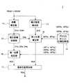
図2は、本発明の実施形態にかかる位置推定装置1の構成を示す機能ブロック図である。本発明の実施形態にかかる位置推定装置1は、距離推定部11、推定距離記録部12、最大強度検出部13、アクセスポイント位置記録部14、第一位置推定部15、第二位置推定部16、最終位置推定部17を備える。 FIG. 2 is a functional block diagram showing the configuration of the
距離推定部11は、信号を受信するアクセスポイントAP1〜AP4と無線通信器RDとの距離である実距離D1〜D4を、信号の受信強度RSSI1〜RSSI4、伝搬係数pf(後述する)および無線通信器RDの送信出力Txp[dBm]に基づき推定して推定距離D1e〜D4eとする。なお、距離推定部11は、受信強度RSSI1〜RSSI4を、アクセスポイントAP1〜AP4から受ける。 The
図4は、距離推定部11の構成を示す機能ブロック図である。距離推定部11は、伝搬係数付与部112、無線デバイス出力付与部114、距離導出部116を有する。 FIG. 4 is a functional block diagram showing the configuration of the
距離導出部116は、受信強度RSSI1〜RSSI4をアクセスポイントAP1〜AP4から受け、伝搬係数pf(無次元数である)を伝搬係数付与部112から受け、無線通信器RDの送信出力Txp[dBm]を無線デバイス出力付与部114から受ける。距離導出部116は、推定距離Die(ただし、iは1〜4の整数)の導出を、以下の式(1)により行う。 The

伝搬係数付与部112は、伝搬係数pfを距離導出部116に付与する。 The propagation
図5は、伝搬係数付与部112の構成を示す機能ブロック図である。伝搬係数付与部112は、アクセスポイント間距離導出部112a、アクセスポイント出力記録部112b、伝搬係数導出部112cを有する。 FIG. 5 is a functional block diagram showing the configuration of the propagation
ここで、あるアクセスポイントAPi(ただし、iは1〜4の整数)が、他のアクセスポイントAPj(ただし、jはiと異なる1〜4の整数)から受けたアクセスポイント間通信信号の受信強度を、RSSI−APijとする。あるアクセスポイントAPiと、他のアクセスポイントAPjとの距離をLij[m]とする。他のアクセスポイントAPjの送信出力をTxp−APj[dBm]とする。 Here, the reception strength of the communication signal between access points received by one access point APIi (where i is an integer of 1 to 4) from another access point APj (where j is an integer of 1 to 4 different from i). Let be RSSI-APIj. Let Lij [m] be the distance between a certain access point APIi and another access point APj. Let the transmission output of the other access point APj be Txp-APj [dBm].
アクセスポイント間距離導出部112aは、後述するアクセスポイント位置記録部14から、アクセスポイントAPiおよびAPjのx座標およびy座標を読み出し、距離Lijを導出する。 The access point
アクセスポイント出力記録部112bは、送信出力Txp−AP0〜Txp−AP4を記録する。 The access point
伝搬係数導出部112cは、受信強度RSSI−APijをAPiから受け、距離Lijをアクセスポイント間距離導出部112aから受け、送信出力Txp−APjをアクセスポイント出力記録部112bから読み出す。伝搬係数導出部112cは、伝搬係数を、受信強度RSSI−APijと、距離Lijと、送信出力Txp−APjとに基づき導出する。具体的には、伝搬係数導出部112cは、以下の式(2)により、伝搬係数pfを導出して、距離導出部116に付与する。ただし、式(2)においては、Txp−APjをTxpと、RSSI−APijをRSSIと、LijをLと表記している。また、λはアクセスポイント間通信信号の波長[m]である。 The propagation
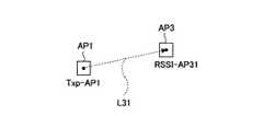
図6は、AP1からAP3へアクセスポイント間通信信号を送信した場合の、AP3における受信強度、AP1とAP3との間の距離、AP1の送信出力を示す図である。図6を参照して、伝搬係数pfの導出法を説明する。
FIG. 6 is a diagram showing the reception strength in AP3, the distance between AP1 and AP3, and the transmission output of AP1 when the communication signal between access points is transmitted from AP1 to AP3. A method for deriving the propagation coefficient pf will be described with reference to FIG.
AP1(他のアクセスポイント)から、送信出力Txp−AP1で、AP3(あるアクセスポイント)へ、アクセスポイント間通信信号を送信すると、AP3で、受信強度RSSI−AP31で受信される。なお、AP1とAP3との距離はL31である。そこで、送信出力Txp−AP1を式(2)のTxpに、受信強度RSSI−AP31を式(2)のRSSIに、L31を式(2)のLに代入して、伝搬係数pfを導出する。 When an access point-to-access point communication signal is transmitted from AP1 (another access point) to AP3 (a certain access point) by the transmission output Txp-AP1, it is received by AP3 with a reception strength RSSI-AP31. The distance between AP1 and AP3 is L31. Therefore, the transmission output Txp-AP1 is substituted into the Txp of the equation (2), the reception intensity RSSI-AP31 is substituted into the RSSI of the equation (2), and L31 is substituted into the L of the equation (2) to derive the propagation coefficient pf.
なお、受信強度RSSI−APijは、測定時点が異なる複数の受信強度の平均値を用いてもよい。例えば、1時間ごとに測定を行うとして、24時間分の測定値の平均値を用いてもよい。 As the reception intensity RSSI-APij, an average value of a plurality of reception intensities at different measurement time points may be used. For example, assuming that the measurement is performed every hour, the average value of the measured values for 24 hours may be used.
また、図6の例でいえば、他のアクセスポイントはAP1のみであったが、さらに、他のアクセスポイントとしてAP4があってもよいし、さらに、AP2があってもよい。このように、他のアクセスポイントが2台以上存在してもかまわない。この場合、あるアクセスポイントがAP3の場合、他のアクセスポイントがAP1のときの伝搬係数pf31、他のアクセスポイントがAP2のときの伝搬係数pf32および他のアクセスポイントがAP4のときの伝搬係数pf34が伝搬係数導出部112cにより式(2)を用いて導出されることになる。この場合、AP3近傍の伝搬係数として、これら3種類の値(pf31、pf32および伝搬係数pf34)の平均値を用いるようにしてもよい。 Further, in the example of FIG. 6, the other access point is only AP1, but AP4 may be further used as another access point, and AP2 may be further provided. In this way, two or more other access points may exist. In this case, when one access point is AP3, the propagation coefficient pf31 when the other access point is AP1, the propagation coefficient pf32 when the other access point is AP2, and the propagation coefficient pf34 when the other access point is AP4 are It is derived by the propagation
無線デバイス出力付与部114は、無線通信器RDの送信出力Txp[dBm]を距離導出部116に付与する。 The wireless device
図7は、無線デバイス出力付与部114の構成を示す機能ブロック図である。無線デバイス出力付与部114は、無線デバイス出力候補値導出部114a、候補値記録部114b、最大値決定部114cを有する。 FIG. 7 is a functional block diagram showing the configuration of the wireless device
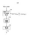
無線デバイス出力候補値導出部114aは、受信強度RSSI1〜RSSI4をアクセスポイントAP1〜AP4から受け、全てのアクセスポイントAP1〜AP4における無線デバイスRDからの信号の受信強度の最大値に基づき、無線デバイスRDの送信出力の候補値を導出する。 The wireless device output candidate
ただし、無線デバイスRDからの信号の受信強度が最大値をとったアクセスポイントの近傍(例えば、1m以内)に無線デバイスRDが存在しているものと仮定し、かつ近傍が自由空間であるものと仮定して、無線デバイスRDの送信出力の候補値が決定される。 However, it is assumed that the wireless device RD exists in the vicinity (for example, within 1 m) of the access point where the reception strength of the signal from the wireless device RD is the maximum value, and the vicinity is a free space. Assuming, the candidate value of the transmission output of the wireless device RD is determined.
具体的には、無線デバイス出力候補値導出部114aは、以下の式(3)により、伝搬係数pfを導出して、距離導出部116に付与する。ただし、式(3)においては、受信強度RSSI1〜RSSI4の最大値をRSSIと表記している。また、λは無線通信器RDの送信した信号の波長[m]である。 Specifically, the wireless device output candidate
候補値記録部114bは、無線デバイス出力候補値導出部114aにより導出された無線デバイスRDの送信出力の候補値を記録する。 The candidate
最大値決定部114cは、候補値記録部114bに記録された候補値の最大値を無線デバイスRDの送信出力とする。 The maximum
候補値が、全てのアクセスポイントAP1〜AP4における無線デバイスRDからの信号の受信強度の最大値に基づき決定される。しかも、候補値の最大値が無線デバイスRDの送信出力となる。このため、全てのアクセスポイントAP1〜AP4における無線デバイスRDからの信号の受信強度の最大値に基づき、無線デバイスRDの送信出力が決定される。 The candidate value is determined based on the maximum value of the reception strength of the signal from the wireless device RD in all the access points AP1 to AP4. Moreover, the maximum value of the candidate value is the transmission output of the wireless device RD. Therefore, the transmission output of the wireless device RD is determined based on the maximum value of the reception strength of the signal from the wireless device RD in all the access points AP1 to AP4.
図8は、移動する無線デバイスRDの移動位置の例を概説する図である。まず、時間t=t1において、無線デバイスRDはアクセスポイントAP1の左方にあり、AP1〜AP4のうちAP1に最も近く、RSSI1〜RSSI4のうちRSSI1が最大である。よって、無線デバイス出力候補値導出部114aは、式(3)のRSSIに(図8(a)における)RSSI1を代入して、無線デバイスRDの送信出力の候補値を導出し、候補値記録部114bに記録する。ただし、この候補値は、無線デバイスRDがAP1の近傍(1m以内)にはないので、不正確な値である。 FIG. 8 is a diagram illustrating an example of a moving position of the moving wireless device RD. First, at time t = t1, the wireless device RD is to the left of the access point AP1, is closest to AP1 among AP1 to AP4, and RSSI1 is the largest among RSSI1 to RSSI4. Therefore, the wireless device output candidate
次に、時間t=t2(>t1)において、無線デバイスRDはアクセスポイントAP3の1m以内にあり、AP1〜AP4のうちAP3に最も近く、RSSI1〜RSSI4のうちRSSI3が最大である。よって、無線デバイス出力候補値導出部114aは、式(3)のRSSIに(図8(b)における)RSSI3を代入して、無線デバイスRDの送信出力の候補値を導出し、候補値記録部114bに記録する。なお、この候補値は、無線デバイスRDがAP3の近傍(1m以内)にあるので、正確な値である。 Next, at time t = t2 (> t1), the wireless device RD is within 1 m of the access point AP3, is closest to AP3 among AP1 to AP4, and RSSI3 is the largest among RSSI1 to RSSI4. Therefore, the wireless device output candidate
最後に、時間t=t3(>t2)において、無線デバイスRDはアクセスポイントAP4の右方にあり、AP1〜AP4のうちAP4に最も近く、RSSI1〜RSSI4のうちRSSI4が最大である。よって、無線デバイス出力候補値導出部114aは、式(3)のRSSIに(図8(c)における)RSSI4を代入して、無線デバイスRDの送信出力の候補値を導出し、候補値記録部114bに記録する。ただし、この候補値は、無線デバイスRDがAP4の近傍(1m以内)にはないので、不正確な値である。 Finally, at time t = t3 (> t2), the wireless device RD is to the right of the access point AP4, closest to AP4 among AP1 to AP4, and RSSI4 of RSSI1 to RSSI4 is the largest. Therefore, the wireless device output candidate
なお、無線デバイスRDは移動するうちに、アクセスポイントのいずれかの近傍に入ることが一般的である。また、アクセスポイントが新たに追加されることで、無線デバイスRDが新たに追加されたアクセスポイントの近傍に入ることもある。 It should be noted that the wireless device RD generally enters the vicinity of any of the access points while moving. In addition, when an access point is newly added, the wireless device RD may enter the vicinity of the newly added access point.
式(3)の2項目以降は、図8(a)、(b)および(c)いずれも同じ値をとる。よって、式(3)におけるRSSIが最大であれば、候補値が最大となる。ここで、式(3)におけるRSSIは、図8(b)の場合が、図8(a)および(c)の場合よりも、無線デバイスRDとアクセスポイントとの距離が短いので、図8(b)の場合が最大値をとる。よって、候補値記録部114bに記録された図8(a)の場合の候補値、図8(b)の場合の候補値および図8(c)の場合の候補値のうち、最大値は、図8(b)の場合の候補値となる。よって、無線デバイスRDの送信出力は、図8(b)の場合の候補値(すなわち正確な値)となる。 The second and subsequent items of the formula (3) have the same values in all of FIGS. 8 (a), (b) and (c). Therefore, if the RSSI in the equation (3) is the maximum, the candidate value is the maximum. Here, the RSSI in the equation (3) is shown in FIG. 8 (b) because the distance between the wireless device RD and the access point is shorter in the case of FIGS. 8 (b) than in the cases of FIGS. 8 (a) and 8 (c). The case of b) takes the maximum value. Therefore, among the candidate values in the case of FIG. 8 (a), the candidate values in the case of FIG. 8 (b), and the candidate values in the case of FIG. 8 (c) recorded in the candidate
推定距離記録部12は、距離推定部11により推定された推定距離D1e〜D4eを、距離推定部11から受けて記録する。 The estimated
最大強度検出部13は、受信強度RSSI1〜RSSI4を、アクセスポイントAP1〜AP4から受け、最大の受信強度を検出し、最大の受信強度が測定されたアクセスポイント(図1の例では、AP3)を出力する。 The maximum
アクセスポイント位置記録部14は、アクセスポイントAP0〜AP4の位置を記録する。例えば、アクセスポイント位置記録部14は、アクセスポイントAP0〜AP4のx座標およびy座標(AP0x、AP0y)〜(AP4x、AP4y)を記録する。 The access point
第一位置推定部15は、いずれか3点以上のアクセスポイントの推定距離に基づき、無線通信器RDの位置を推定する。例えば、推定距離D1e〜D4eのうち、小さい方から3つ(例えば、AP1の推定距離D1e、AP3の推定距離D3e、AP4の推定距離D4e)に基づき、3点測位により無線通信器RDの位置を推定する。なお、第一位置推定部15は、推定距離D1e、D3e、D4eを推定距離記録部12から読み出し、AP1、AP3、AP4のxy座標(AP1x、AP1y)、(AP3x、AP3y)、(AP4x、AP4y)をアクセスポイント位置記録部14から読み出して、3点測位に用いる。 The first
また、第一位置推定部15によって推定された無線通信器RDの位置を第一推定位置RD1という。 Further, the position of the wireless communication device RD estimated by the first
第二位置推定部16は、受信強度が最大のアクセスポイントAP3を中心として、推定距離のうちその中心(アクセスポイントAP3)について推定されたものD3eを半径とする円周RD2上を、無線通信器RDの位置であると推定する。なお、第二位置推定部16は、最大強度検出部13からAP3を受け、AP3に関する情報を推定距離記録部12およびアクセスポイント位置記録部14から読み出し(すなわち、推定距離D3eを推定距離記録部12から読み出し、AP3のxy座標(AP3x、AP3y)をアクセスポイント位置記録部14から読み出し)、円周RD2の導出に用いる。 The second
また、第二位置推定部16によって推定された無線通信器RDの位置(円周RD2)を第二推定位置RD2という。 Further, the position (circumference RD2) of the wireless communication device RD estimated by the second
最終位置推定部17は、第一位置推定部15から第一推定位置RD1を受け、第二位置推定部16から第二推定位置RD2およびその中心AP3を受け、アクセスポイントAP3を一端とし第一推定位置RD1を通る半直線と、第二推定位置RD2との交点RDeを無線通信器RDの位置であると推定する。なお、最終位置推定部17により推定された位置(最終推定位置という)RDeが、無線通信器RDの位置として推定される。 The final position estimation unit 17 receives the first estimated position RD1 from the first
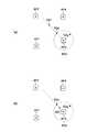
図3は、無線通信器RDの第一推定位置RD1、第二推定位置RD2および最終推定位置RDeの一例を示す図である。 FIG. 3 is a diagram showing an example of the first estimated position RD1, the second estimated position RD2, and the final estimated position RDe of the wireless communication device RD.
図3(a)の例では、アクセスポイントAP3の左上に第一推定位置RD1があり、第一推定位置RD1は第二推定位置(円周)RD2の外にある。最終推定位置RDeは、アクセスポイントAP3の左上の第二推定位置RD2上にある。 In the example of FIG. 3A, the first estimated position RD1 is located on the upper left of the access point AP3, and the first estimated position RD1 is outside the second estimated position (circumference) RD2. The final estimated position RDe is on the second estimated position RD2 on the upper left of the access point AP3.
図3(b)の例では、アクセスポイントAP3の左上に第一推定位置RD1があり、第一推定位置RD1は第二推定位置(円周)RD2の内にある。この場合も、最終推定位置RDeは、アクセスポイントAP3の左上の第二推定位置RD2上にある。 In the example of FIG. 3B, the first estimated position RD1 is located on the upper left of the access point AP3, and the first estimated position RD1 is within the second estimated position (circumference) RD2. In this case as well, the final estimated position RDe is on the second estimated position RD2 on the upper left of the access point AP3.
次に、本発明の実施形態の動作を説明する。 Next, the operation of the embodiment of the present invention will be described.
図1に示すように、アクセスポイントAP0〜AP4および無線デバイスRDが配置されているとする。無線デバイスRDから信号が送信され、アクセスポイントAP1〜AP4が受信する。アクセスポイントAP0は、無線デバイスRDから遠すぎるので、無線デバイスRDからの信号を受信できない。 As shown in FIG. 1, it is assumed that the access points AP0 to AP4 and the wireless device RD are arranged. A signal is transmitted from the wireless device RD and received by access points AP1 to AP4. The access point AP0 is too far from the wireless device RD to receive the signal from the wireless device RD.
アクセスポイントAP1〜AP4は、それぞれ、無線通信器RDから送信された信号の受信強度RSSI1〜RSSI4を測定し、位置推定装置1に与える。 The access points AP1 to AP4 each measure the reception strength RSSI1 to RSSI4 of the signal transmitted from the wireless communication device RD and give it to the
位置推定装置1の距離推定部11(図2参照)は、受信強度RSSI1〜RSSI4を受け、実距離D1〜D4(図1参照)を推定する。推定は、距離導出部116(図4参照)が、上記の式(1)を用いて行う。ただし、式(1)における伝搬係数pfは、伝搬係数付与部112より距離導出部116に与えられ(図4〜図6および式(2)参照)、式(1)における無線通信器RDの送信出力Txp[dBm]は、無線デバイス出力付与部114より距離導出部116に与えられる(図4、図7、図8および式(3)参照)。距離推定部11による推定結果である推定距離D1e〜D4eは、推定距離記録部12に記録される。 The distance estimation unit 11 (see FIG. 2) of the
位置推定装置1の最大強度検出部13は、受信強度RSSI1〜RSSI4を受け、最大の受信強度が測定されたアクセスポイント(図1の例では、AP3)を、第二位置推定部16に与える。 The maximum
第二位置推定部16は、最大強度検出部13から、最大の受信強度が測定されたアクセスポイント(図1の例では、AP3)を受け、推定距離記録部12からAP3に対応した推定距離D3eを読み出し、アクセスポイント位置記録部14からAP3のx座標およびy座標(AP3x、AP3y)を読み出す。第二位置推定部16は、さらに、読み出した推定距離D3eおよびAP3の座標(AP3x、AP3y)を用いて、第二推定位置RD2(AP3を中心とした半径D3eの円周)を決定する(図3参照)。 The second
第一位置推定部15は、推定距離D1e〜D4eのうち、小さい方から3つ(例えば、推定距離D1e、D3e、D4e)を推定距離記録部12から読み出し、推定距離D1e、D3e、D4eに対応するAP1、AP3、AP4のxy座標(AP1x、AP1y)、(AP3x、AP3y)、(AP4x、AP4y)をアクセスポイント位置記録部14から読み出して、3点測位により、無線通信器RDの位置を推定する(第一推定位置RD1)(図3参照)。 The first
最終位置推定部17は、第一位置推定部15から第一推定位置RD1を受け、第二位置推定部16から第二推定位置RD2およびその中心AP3を受ける。最終位置推定部17は、アクセスポイントAP3を一端とし第一推定位置RD1を通る半直線と、第二推定位置RD2との交点RDeを無線通信器RDの位置であると推定する(最終推定位置RDe)(図3参照)。 The final position estimation unit 17 receives the first estimated position RD1 from the first
本発明の実施形態によれば、第一推定位置RD1は、推定距離D1e〜D4eのうち3種以上の値に基づき推定されるものであるところ、距離の推定の精度によっては、第一推定位置RD1が無線通信器RDの真の位置とは一致しないことがある。また、第二推定位置RD2は、受信強度が最大のアクセスポイントAP3の測定した受信強度に基づくものなので、距離の推定の精度も高く、無線通信器RDの真の位置に近いとはいえるが、受信強度が最大のアクセスポイントAP3から見てどの方向(例えば、上下左右のいずれか)に無線通信器RDがあるのかが分からない。そこで、第一推定位置RD1および第二推定位置RD2を組み合わせて、最終推定位置RDeを導出したので、無線通信器RDの位置の推定を精度良く行うことができる。 According to the embodiment of the present invention, the first estimated position RD1 is estimated based on three or more values of the estimated distances D1e to D4e, and the first estimated position depends on the accuracy of the distance estimation. The RD1 may not match the true position of the wireless communicator RD. Further, since the second estimated position RD2 is based on the reception strength measured by the access point AP3 having the maximum reception strength, the accuracy of distance estimation is high, and it can be said that it is close to the true position of the wireless communication device RD. It is unknown in which direction (for example, up, down, left, or right) the wireless communication device RD is located when viewed from the access point AP3 having the maximum reception strength. Therefore, since the final estimated position RDe is derived by combining the first estimated position RD1 and the second estimated position RD2, the position of the wireless communication device RD can be estimated accurately.
しかも、本発明の実施形態によれば、伝搬係数付与部112および無線デバイス出力付与部114が、推定距離D1e〜D4eの導出の際に用いる伝搬係数pfおよび無線通信器RDの送信出力Txp[dBm]を、アクセスポイントによる測定結果(受信強度)により求めるので、推定距離D1e〜D4eの推定精度が向上し、ひいては、無線通信器RDの位置の推定を精度良く行うことができる。 Moreover, according to the embodiment of the present invention, the propagation coefficient pf used by the propagation
また、上記の実施形態は、以下のようにして実現できる。CPU、ハードディスク、メディア(USBメモリ、CD−ROMなど)読み取り装置を備えたコンピュータに、上記の各部分、例えば位置推定装置1の各部分を実現するプログラムを記録したメディアを読み取らせて、ハードディスクにインストールする。このような方法でも、上記の機能を実現できる。 Further, the above embodiment can be realized as follows. A computer equipped with a CPU, a hard disk, and a media (USB memory, CD-ROM, etc.) reading device is made to read the media on which the program for realizing each of the above parts, for example, each part of the
1 位置推定装置
11 距離推定部
112 伝搬係数付与部
114 無線デバイス出力付与部
116 距離導出部
12 推定距離記録部
13 最大強度検出部
14 アクセスポイント位置記録部
15 第一位置推定部
16 第二位置推定部
17 最終位置推定部
AP0、AP1、AP2、AP3、AP4 無線LANアクセスポイント
RD 無線デバイス(無線通信器)
RD1 第一推定位置
RD2 第二推定位置
RDe 最終推定位置
RSSI1〜RSSI4 受信強度
D1、D2、D3、D4 実距離
D1e〜D4e 推定距離1
RD1 First estimated position RD2 Second estimated position RDe Final estimated position RSSI1 to RSSI4 Reception strength D1, D2, D3, D4 Actual distance D1e to D4e Estimated distance
Claims (7)
Translated fromJapanese前記信号を受信する無線アクセスポイントと前記無線通信器との距離である実距離を、前記信号の受信強度に基づき推定して推定距離とする距離推定部と、
いずれか3点以上の前記無線アクセスポイントの前記推定距離に基づき、前記無線通信器の位置を推定する第一位置推定部と、
前記受信強度が最大の前記無線アクセスポイントを中心として、前記推定距離のうち前記中心について推定されたものを半径とする円周上を、前記無線通信器の位置であると推定する第二位置推定部と、
前記中心を一端とし前記第一位置推定部によって推定された位置を通る半直線と、前記円周との交点を前記無線通信器の位置であると推定する最終位置推定部と、
を備え、
前記最終位置推定部により推定された位置が、前記無線通信器の位置として推定される、
位置推定装置。A position estimation device that estimates the position of a wireless communication device that outputs a signal.
A distance estimation unit that estimates the actual distance, which is the distance between the wireless access point that receives the signal and the wireless communication device, based on the reception strength of the signal and uses it as the estimated distance.
A first position estimation unit that estimates the position of the wireless communication device based on the estimated distance of the wireless access point at any three or more points.
Second position estimation that estimates the position of the wireless communication device on the circumference with the radius estimated for the center of the estimated distance centered on the wireless access point with the maximum reception strength. Department and
A final position estimation unit that estimates that the intersection of a half straight line passing through a position estimated by the first position estimation unit with the center as one end and the circumference is the position of the wireless communication device.
With
The position estimated by the final position estimation unit is estimated as the position of the wireless communication device.
Position estimator.
前記距離推定部が、さらに伝搬係数に基づいて前記推定距離を推定し、
前記伝搬係数が、
ある前記無線アクセスポイントが、他の前記無線アクセスポイントから受けたアクセスポイント間通信信号の受信強度と、
ある前記無線アクセスポイントと、他の前記無線アクセスポイントとの距離と、
他の前記無線アクセスポイントの送信出力と、
に基づいて決定される、
位置推定装置。The position estimation device according to claim 1.
The distance estimation unit further estimates the estimated distance based on the propagation coefficient.
The propagation coefficient is
The reception strength of the communication signal between access points received by one wireless access point from another wireless access point, and
The distance between one wireless access point and the other wireless access point,
With the transmission output of the other wireless access point
Determined based on
Position estimator.
前記受信強度として、測定時点が異なる複数の前記受信強度の平均値を用いる、
位置推定装置。The position estimation device according to claim 2.
As the reception intensity, the average value of a plurality of the reception intensities at different measurement points is used.
Position estimator.
他の前記無線アクセスポイントが2台以上存在し、
前記伝搬係数として、2台以上の他の前記無線アクセスポイントについての伝搬係数の平均値を用いる、
位置推定装置。The position estimation device according to claim 2.
There are two or more other wireless access points,
As the propagation coefficient, the average value of the propagation coefficients for two or more other wireless access points is used.
Position estimator.
前記距離推定部が、さらに前記無線通信器の送信出力に基づいて前記推定距離を推定し、
全ての前記無線アクセスポイントにおける前記信号の受信強度の最大値に基づき、前記無線通信器の送信出力が決定される、
位置推定装置。The position estimation device according to claim 1.
The distance estimation unit further estimates the estimated distance based on the transmission output of the wireless communication device.
The transmission output of the wireless communication device is determined based on the maximum value of the reception strength of the signal at all the wireless access points.
Position estimator.
前記信号の受信強度が最大値をとった前記無線アクセスポイントの近傍に前記無線通信器が存在しているものと仮定し、かつ前記近傍が自由空間であるものと仮定して、前記無線通信器の送信出力が決定される、
位置推定装置。The position estimation device according to claim 5.
It is assumed that the wireless communication device is present in the vicinity of the wireless access point where the reception strength of the signal is the maximum value, and that the vicinity is free space. Transmission output is determined,
Position estimator.
前記信号を受信する無線アクセスポイントと前記無線通信器との距離である実距離を、前記信号の受信強度に基づき推定して推定距離とする距離推定工程と、
いずれか3点以上の前記無線アクセスポイントの前記推定距離に基づき、前記無線通信器の位置を推定する第一位置推定工程と、
前記受信強度が最大の前記無線アクセスポイントを中心として、前記推定距離のうち前記中心について推定されたものを半径とする円周上を、前記無線通信器の位置であると推定する第二位置推定工程と、
前記中心を一端とし前記第一位置推定工程によって推定された位置を通る半直線と、前記円周との交点を前記無線通信器の位置であると推定する最終位置推定工程と、
を備え、
前記最終位置推定工程により推定された位置が、前記無線通信器の位置として推定される、
位置推定方法。A position estimation method that estimates the position of a wireless communication device that outputs a signal.
A distance estimation step in which the actual distance, which is the distance between the wireless access point receiving the signal and the wireless communication device, is estimated based on the reception strength of the signal and used as the estimated distance.
A first position estimation step for estimating the position of the wireless communication device based on the estimated distance of the wireless access point at any three or more points, and
Second position estimation that estimates the position of the wireless communication device on the circumference with the radius estimated for the center of the estimated distance centered on the wireless access point with the maximum reception strength. Process and
A final position estimation step of estimating that the intersection of a half straight line passing through a position estimated by the first position estimation step with the center as one end and the circumference is the position of the wireless communication device.
With
The position estimated by the final position estimation step is estimated as the position of the wireless communication device.
Position estimation method.
Priority Applications (2)
| Application Number | Priority Date | Filing Date | Title |
|---|---|---|---|
| JP2019116233AJP2021001833A (en) | 2019-06-24 | 2019-06-24 | Position estimating device and method |
| US16/909,227US11296803B2 (en) | 2019-06-24 | 2020-06-23 | Apparatus and method for position estimation |
Applications Claiming Priority (1)
| Application Number | Priority Date | Filing Date | Title |
|---|---|---|---|
| JP2019116233AJP2021001833A (en) | 2019-06-24 | 2019-06-24 | Position estimating device and method |
Publications (2)
| Publication Number | Publication Date |
|---|---|
| JP2021001833Atrue JP2021001833A (en) | 2021-01-07 |
| JP2021001833A5 JP2021001833A5 (en) | 2022-06-02 |
Family
ID=73994153
Family Applications (1)
| Application Number | Title | Priority Date | Filing Date |
|---|---|---|---|
| JP2019116233APendingJP2021001833A (en) | 2019-06-24 | 2019-06-24 | Position estimating device and method |
Country Status (2)
| Country | Link |
|---|---|
| US (1) | US11296803B2 (en) |
| JP (1) | JP2021001833A (en) |
Cited By (1)
| Publication number | Priority date | Publication date | Assignee | Title |
|---|---|---|---|---|
| JP2023132585A (en)* | 2022-03-11 | 2023-09-22 | ソフトバンク株式会社 | Device to be positioned, reference device, positioning system, management device, positioning method, and program |
Citations (4)
| Publication number | Priority date | Publication date | Assignee | Title |
|---|---|---|---|---|
| US20120081249A1 (en)* | 2003-07-28 | 2012-04-05 | Kaiser Daryl A | Radiolocation using path loss data |
| US20130045750A1 (en)* | 2011-08-19 | 2013-02-21 | Snu R&Db Foundation | Wireless localization method based on an efficient multilateration algorithm over a wireless sensor network and a recording medium in which a program for the method is recorded |
| JP2016142637A (en)* | 2015-02-02 | 2016-08-08 | 富士通株式会社 | Mobile device, position estimation method, and position estimation program |
| WO2018100892A1 (en)* | 2016-11-29 | 2018-06-07 | 株式会社村田製作所 | Position estimation apparatus and position estimation method |
Family Cites Families (13)
| Publication number | Priority date | Publication date | Assignee | Title |
|---|---|---|---|---|
| JP4586690B2 (en) | 2005-09-09 | 2010-11-24 | 沖電気工業株式会社 | Position estimation system |
| US20090303114A1 (en)* | 2008-06-06 | 2009-12-10 | Skyhook Wireless, Inc. | Method and system for determining location using a hybrid satellite and wlan positioning system by selecting the best wlan-ps solution |
| US10168414B2 (en)* | 2014-07-17 | 2019-01-01 | Origin Wireless, Inc. | Wireless signals and techniques for determining locations of objects in multi-path environments |
| KR101252946B1 (en)* | 2011-03-03 | 2013-04-15 | 연세대학교 산학협력단 | Apparatus and method for constructing wireless lan ap map |
| US8611247B2 (en)* | 2012-01-24 | 2013-12-17 | Qualcomm Incorporated | Dynamic data retrieval in a WLAN positioning system |
| KR102016692B1 (en)* | 2013-08-28 | 2019-09-02 | 삼성전자 주식회사 | Method and its apparatus for connecting to access point in wireless lan system |
| KR20150079080A (en)* | 2013-12-31 | 2015-07-08 | 한국전자통신연구원 | Positioning method based on reliability and apparatus thereof |
| KR102207584B1 (en)* | 2014-04-03 | 2021-01-26 | 한국전자통신연구원 | Method and apparatus of intergrated positioning |
| US20150319580A1 (en)* | 2014-04-30 | 2015-11-05 | Samsung Electro-Mechanics Co., Ltd. | Wireless position estimation apparatus and method |
| JP6532606B2 (en) | 2016-05-18 | 2019-06-19 | 学校法人 関西大学 | Position estimation device |
| CN106455049B (en)* | 2016-09-18 | 2020-03-03 | 北京小米移动软件有限公司 | Positioning method and device based on wireless local area network |
| US11310118B2 (en)* | 2019-01-21 | 2022-04-19 | Hewlett Packard Enterprise Development Lp | Tracking randomized addresses in bluetooth devices |
| US11297590B2 (en)* | 2019-03-01 | 2022-04-05 | Hughes Network Systems, Llc | Multilateration method, multilateration device and multilateration system |
- 2019
- 2019-06-24JPJP2019116233Apatent/JP2021001833A/enactivePending
- 2020
- 2020-06-23USUS16/909,227patent/US11296803B2/enactiveActive
Patent Citations (4)
| Publication number | Priority date | Publication date | Assignee | Title |
|---|---|---|---|---|
| US20120081249A1 (en)* | 2003-07-28 | 2012-04-05 | Kaiser Daryl A | Radiolocation using path loss data |
| US20130045750A1 (en)* | 2011-08-19 | 2013-02-21 | Snu R&Db Foundation | Wireless localization method based on an efficient multilateration algorithm over a wireless sensor network and a recording medium in which a program for the method is recorded |
| JP2016142637A (en)* | 2015-02-02 | 2016-08-08 | 富士通株式会社 | Mobile device, position estimation method, and position estimation program |
| WO2018100892A1 (en)* | 2016-11-29 | 2018-06-07 | 株式会社村田製作所 | Position estimation apparatus and position estimation method |
Cited By (2)
| Publication number | Priority date | Publication date | Assignee | Title |
|---|---|---|---|---|
| JP2023132585A (en)* | 2022-03-11 | 2023-09-22 | ソフトバンク株式会社 | Device to be positioned, reference device, positioning system, management device, positioning method, and program |
| JP7520912B2 (en) | 2022-03-11 | 2024-07-23 | ソフトバンク株式会社 | Positioning system, positioning method and program |
Also Published As
| Publication number | Publication date |
|---|---|
| US20200403716A1 (en) | 2020-12-24 |
| US11296803B2 (en) | 2022-04-05 |
Similar Documents
| Publication | Publication Date | Title |
|---|---|---|
| JP5741223B2 (en) | Information processing apparatus, correction method, and correction program | |
| US7969913B2 (en) | Localization apparatus for recognizing location of node in sensor network and method thereof | |
| JP6296454B2 (en) | Positioning method and apparatus by base station | |
| US20170293012A1 (en) | Location determination system and location determination program | |
| US10382892B2 (en) | Bluetooth device locator | |
| JP2007013500A (en) | Wireless terminal position estimation system, wireless terminal position estimation system position estimation method, and data processing apparatus | |
| CN107547598B (en) | A positioning method, server and terminal | |
| JP2010190629A (en) | Location estimating device, wireless terminal device, and location estimating system | |
| WO2019136966A1 (en) | Method and device for positioning terminal | |
| JP2021001833A (en) | Position estimating device and method | |
| KR101650077B1 (en) | A Positioning System and Method thereof | |
| JP2017090284A (en) | Location determination program, location determination method and location determination device | |
| KR101685164B1 (en) | Communication terminal and computer program for using selected access points | |
| JP7272050B2 (en) | Position estimation device, position estimation method and position estimation program | |
| KR20190136619A (en) | Positioning system enabling continuous updating of positions of the WLAN APs leading to more accurate values and method for the same | |
| JP5379312B2 (en) | Distance measuring device | |
| JPWO2018100892A1 (en) | Position estimation apparatus and position estimation method | |
| JP2019092099A (en) | Radio wave environment estimation device and radio wave environment estimation method | |
| KR20200073738A (en) | LOCATION ESTIMATION METHOD AND APPARATUS FOR IoT DEVICE BASED ON BEACON SIGNAL | |
| JP7320387B2 (en) | Location estimation device and method | |
| KR102492309B1 (en) | User terminal and location estimation method using the same | |
| KR101762510B1 (en) | Method for determining mobile reference node to improve the detection accuracy of the location | |
| CN105988109B (en) | Distance measuring method, distance measuring device, positioning device and positioning method | |
| JP6349214B2 (en) | Position estimation apparatus and position estimation program | |
| KR101601961B1 (en) | System and method for tracking location using multi-antenna sensor |
Legal Events
| Date | Code | Title | Description |
|---|---|---|---|
| A521 | Request for written amendment filed | Free format text:JAPANESE INTERMEDIATE CODE: A523 Effective date:20220525 | |
| A621 | Written request for application examination | Free format text:JAPANESE INTERMEDIATE CODE: A621 Effective date:20220525 | |
| A977 | Report on retrieval | Free format text:JAPANESE INTERMEDIATE CODE: A971007 Effective date:20230215 | |
| A131 | Notification of reasons for refusal | Free format text:JAPANESE INTERMEDIATE CODE: A131 Effective date:20230306 | |
| A02 | Decision of refusal | Free format text:JAPANESE INTERMEDIATE CODE: A02 Effective date:20230710 |