JP2021000858A - Transaxle - Google Patents
TransaxleDownload PDFInfo
- Publication number
- JP2021000858A JP2021000858AJP2019114035AJP2019114035AJP2021000858AJP 2021000858 AJP2021000858 AJP 2021000858AJP 2019114035 AJP2019114035 AJP 2019114035AJP 2019114035 AJP2019114035 AJP 2019114035AJP 2021000858 AJP2021000858 AJP 2021000858A
- Authority
- JP
- Japan
- Prior art keywords
- side gear
- motor
- transaxle
- gear
- vehicle
- Prior art date
- Legal status (The legal status is an assumption and is not a legal conclusion. Google has not performed a legal analysis and makes no representation as to the accuracy of the status listed.)
- Pending
Links
Images


Classifications
- Y—GENERAL TAGGING OF NEW TECHNOLOGICAL DEVELOPMENTS; GENERAL TAGGING OF CROSS-SECTIONAL TECHNOLOGIES SPANNING OVER SEVERAL SECTIONS OF THE IPC; TECHNICAL SUBJECTS COVERED BY FORMER USPC CROSS-REFERENCE ART COLLECTIONS [XRACs] AND DIGESTS
- Y02—TECHNOLOGIES OR APPLICATIONS FOR MITIGATION OR ADAPTATION AGAINST CLIMATE CHANGE
- Y02T—CLIMATE CHANGE MITIGATION TECHNOLOGIES RELATED TO TRANSPORTATION
- Y02T10/00—Road transport of goods or passengers
- Y02T10/60—Other road transportation technologies with climate change mitigation effect
- Y02T10/64—Electric machine technologies in electromobility
Landscapes
- Arrangement Of Transmissions (AREA)
- Motor Power Transmission Devices (AREA)
- Arrangement Or Mounting Of Propulsion Units For Vehicles (AREA)
- Motor Or Generator Frames (AREA)
- Connection Of Motors, Electrical Generators, Mechanical Devices, And The Like (AREA)
Abstract
Translated fromJapaneseDescription
Translated fromJapanese本発明は、電気自動車やハイブリッド車など、電力により走行可能な車両に用いられるトランスアクスルに関する。 The present invention relates to a transaxle used in a vehicle that can travel by electric power, such as an electric vehicle or a hybrid vehicle.
従来、電気により走行する電気自動車やハイブリッド車などが提供されている。このような電気自動車などには、EV機器などの高電圧部品が搭載されている。高電圧部品は、高電圧配線を介してモータと接続されている。高電圧配線がモータから外れると、想定外の事態が起こりかねないため、高電圧配線がモータから外れないように、種々の対策が検討されている。 Conventionally, electric vehicles and hybrid vehicles that run on electricity have been provided. High-voltage components such as EV devices are mounted on such electric vehicles. The high voltage component is connected to the motor via high voltage wiring. If the high-voltage wiring is disconnected from the motor, an unexpected situation may occur. Therefore, various measures are being studied to prevent the high-voltage wiring from being disconnected from the motor.
例えば、下記特許文献1には、電力制御装置(インバータ)に取り付けられたコネクタの両側に突起を設け、衝突の衝撃で電力制御装置が後退したとき、突起が車体部を押し退けてコネクタを保護する技術が開示されている。 For example, in
しかしながら、コネクタが取り付けられる電装部品についてコネクタが外れないような対策を検討すると、コネクタ取付部を保護するだけでは十分ではない。また、相手部品の形状によっては特許文献1に開示された突起では、コネクタを保護できない可能性がある。 However, when considering measures to prevent the connector from coming off from the electrical components to which the connector is attached, it is not enough to protect the connector attachment portion. Further, depending on the shape of the mating component, the protrusion disclosed in
高電圧配線が外れると、想定外のトラブルが起こりかねない。そのため、想定外のトラブルの要因となりかねない高電圧配線外れについては、種々の対策や配慮が行われることが望ましい。 If the high voltage wiring is disconnected, unexpected troubles may occur. Therefore, it is desirable to take various measures and consideration for disconnection of high-voltage wiring that may cause unexpected troubles.
そこで本発明は、車両の衝突時などの衝撃に対して、高電圧配線がモータから外れることを抑制することができるトランスアクスルの提供を目的とした。 Therefore, an object of the present invention is to provide a transaxle capable of suppressing disconnection of high-voltage wiring from a motor in the event of an impact such as a vehicle collision.
上述の課題を解決するため提供される本発明のトランスアクスルは、モータと高電圧部品とを備える車両に用いられるトランスアクスルであって、前記モータのモータ軸に対して直列的に接続される入力側ギアと、前記入力側ギアと噛み合う出力側ギアとを備える減速機構と、前記出力側ギアから伝達された動力を車輪に伝達するデファレンシャル機構とを有し、前記入力側ギアの軸線、及び前記出力側ギアの軸線は、車両の前後方向に延びており、前記出力側ギアは、前記入力側ギアに対して車両の幅方向にオフセットして配置されていることを特徴とするものである。 The transaxle of the present invention provided to solve the above problems is a transaxle used in a vehicle including a motor and a high-voltage component, and is an input connected in series with the motor shaft of the motor. It has a reduction mechanism including a side gear and an output side gear that meshes with the input side gear, and a differential mechanism that transmits power transmitted from the output side gear to the wheels, and has an axis of the input side gear and the said. The axis of the output-side gear extends in the front-rear direction of the vehicle, and the output-side gear is arranged so as to be offset in the width direction of the vehicle with respect to the input-side gear.
本発明のトランスアクスルによれば、衝突時に、初めに加重を受ける出力側ギアがモータ軸と車両の幅方向にオフセットしている。そのため、本発明のトランスアクスルでは、モータに荷重が伝わりにくく、モータに接続された高電圧配線がモータから外れることを抑制することができる。その結果、本発明のトランスアクスルは、高電圧配線が外れることに起因する想定外のトラブルの発生を抑制することができる。 According to the transaxle of the present invention, in the event of a collision, the output side gear that is initially loaded is offset in the width direction of the motor shaft and the vehicle. Therefore, in the transaxle of the present invention, it is difficult for the load to be transmitted to the motor, and it is possible to prevent the high voltage wiring connected to the motor from being disconnected from the motor. As a result, the transaxle of the present invention can suppress the occurrence of unexpected troubles caused by the disconnection of the high voltage wiring.
本発明のトランスアクスルは、少なくとも前記減速機構を収容するトランスアクスルハウジングを備え、前記トランスアクスルハウジングには、前記出力側ギアの前記モータ側に中空の空間が形成された空間部が設けられているものであるとよい。 The transaxle of the present invention includes at least a transaxle housing accommodating the reduction mechanism, and the transaxle housing is provided with a space portion in which a hollow space is formed on the motor side of the output side gear. It should be a thing.
上述の構成によれば、衝突時に出力側ギアの軸体の一端(モータ側の端部)とモータとの間にある空間(空間部)がつぶれることにより、衝突エネルギーを吸収し、より一層モータに荷重が伝わることを低減することができる。 According to the above configuration, the space (space part) between one end (the end on the motor side) of the shaft body of the output side gear and the motor is crushed at the time of a collision, so that the collision energy is absorbed and the motor is further absorbed. It is possible to reduce the transmission of load to the motor.
また、本発明のトランスアクスルは、前記入力側ギア及び前記出力側ギアが、はすば歯車とされており、前記入力側ギアの歯筋と前記出力側ギアの歯筋とが、車両の前方から後方に向けて広がるように角度をなしているものであるとさらによい。 Further, in the transformer axle of the present invention, the input side gear and the output side gear are helical gears, and the tooth muscles of the input side gear and the tooth muscles of the output side gear are in front of the vehicle. It is even better if the angle is such that it spreads from the rear to the rear.
上述の構成によれば、前方からの荷重に対して、出力側ギアと入力側ギアとが離れる方向に荷重を逃がすことができる。その結果、より確実にモータに荷重が伝達されることを抑制することができる。 According to the above configuration, the load can be released in the direction in which the output side gear and the input side gear are separated from each other with respect to the load from the front. As a result, it is possible to prevent the load from being transmitted to the motor more reliably.
本発明のトランスアクスルは、前記減速機構及び前記デファレンシャル機構を収容するトランスアクスルハウジングを備え、前記トランスアクスルハウジングには、車両の前後方向の中間部にくびれ部が形成されているものであるとよい。 The transaxle of the present invention includes a transaxle housing that houses the deceleration mechanism and the differential mechanism, and the transaxle housing may have a constricted portion formed in an intermediate portion in the front-rear direction of the vehicle. ..
上述の構成によれば、トランスアクスル自体を緩衝部材として機能させ、モータに荷重が伝達されるのを回避することができる。その結果、より確実に高電圧部品への影響を抑制することができる。 According to the above configuration, the transaxle itself can function as a cushioning member to prevent the load from being transmitted to the motor. As a result, the influence on the high voltage component can be suppressed more reliably.
本発明によれば、車両の衝突時などの衝撃に対して、高電圧配線がモータから外れることを抑制することができるトランスアクスルを提供することができる。 According to the present invention, it is possible to provide a transaxle capable of suppressing the high voltage wiring from being disconnected from the motor in response to an impact such as a vehicle collision.
以下、本発明の一実施形態に係るトランスアクスル20について、図面を参照しつつ詳細に説明する。 Hereinafter, the
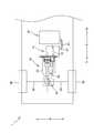
図1に示すとおり、トランスアクスル20は、車両1に設けられている。トランスアクスル20は、モータ10(駆動源)と接続されている。また、車両1には、インバータ(INV)等の高電圧部品80が設けられている。車両1は、トランスアクスル20を介して、モータ10により出力される回転動力を駆動車軸88及び駆動輪86に伝達して駆動可能とされている。 As shown in FIG. 1, the
なお、以下の説明において、車両1の前後方向を、単に「前後方向X」(又は軸線方向X)と記載して説明する場合がある。また、車両1の前後方向Xにおいて、前方を単に「前方Fr」と、後方を単に「後方Rr」と記載して説明する場合がある。さらに、車両1の幅方向を、単に「幅方向W」と記載して説明する場合がある。 In the following description, the front-rear direction of the
高電圧部品80は、図示を省略したバッテリに接続されており、バッテリから電力が供給される。また、高電圧部品80は、高電圧配線82を介してモータ10と接続されており、バッテリから供給された電力をモータ10に供給している。図1に示すとおり、高電圧部品80は、モータ10よりも後方Rr側に配置されており、図示を省略したクロスメンバなどの支持部材により車両1に配置されている。なお、高電圧部品80は、図示を省略した高電圧配線を介してバッテリ(図示を省略)と接続されている。 The
図1に示すとおり、車両1では、前後方向Xに沿って、モータ10とトランスアクスル20とが配置されており、モータ10の前方Fr側にトランスアクスル20が配置されている。また、車両1では、後述する減速機構40に設けられた入力側ギア42の回転軸である軸線L1や、出力側ギア50の回転軸である軸線L2が、車両1の前後方向に沿って配置された、いわゆる縦置きのレイアウトとされている。 As shown in FIG. 1, in the
モータ10は、車両走行用の動力を駆動輪86に向けて出力するモータ機能に加え、発電機能をも有する、いわゆるモータジェネレータとされている。モータ10は、インバータ(図示を省略)を介してバッテリ(図示を省略)から電力が供給されることにより、モータハウジング内においてステータ(図示を省略)に対してロータ(図示を省略)が回転する。また、図2に示すとおり、モータ10は、半径D1とされた径方向の大きさを有している。 The
図2に示すとおり、モータ10は、モータ軸12を備えている。モータ軸12の軸線L1は、前後方向Xに延びている。モータ軸12は、前方Fr側が後述する入力側ギア42と直列的に接続されている。 As shown in FIG. 2, the
図1に示すとおり、モータ10には、高電圧配線82が接続されている。図1に示すとおり、高電圧配線82は、コネクタ84を介してモータ10に接続されている。コネクタ84は、モータ10の側方に取り付けられている。さらに具体的に説明すると、コネクタ84は、モータ10の幅方向Wにおいて、出力側ギア50の軸線L2が延びている側(図1の例では車両1の右側)とは反対側(図1の例では左側)の側方に取り付けられている。 As shown in FIG. 1, a
トランスアクスル20は、減速機構40を構成する複数のギアや軸体を介して、モータ10の回転動力をデファレンシャル機構60に伝達して、一対の駆動輪86の各々に分配して駆動させる。デファレンシャル機構60は、一対の駆動輪86の相互間に回転差が生じた場合には、その回転差を許容しつつ動力伝達を行う。 The
図2に示すとおり、トランスアクスル20は、トランスアクスルハウジング22、減速機構40、及びデファレンシャル機構60を備えている。図1に示すとおり、減速機構40及びデファレンシャル機構60は、トランスアクスルハウジング22に収容されている。 As shown in FIG. 2, the
図1に示すとおり、減速機構40は、入力側ギア42、出力側ギア50、及び中間ギア58を備えている。 As shown in FIG. 1, the
図2に示すとおり、入力側ギア42は、ギア部46と軸部44とが一体的に形成されている。図2に示すとおり、入力側ギア42は、軸部44がモータ軸12に接続されており、モータ10から回転動力が伝達されて回転する。入力側ギア42の軸部44の後方Rr側には、ベアリング72が取り付けられており、入力側ギア42は、ベアリング72を介して後述するギアハウジング32に嵌め込まれてトランスアクスルハウジング22に支持されている。 As shown in FIG. 2, in the
また、入力側ギア42は、軸線L1が車両1の前後方向Xに延びている。入力側ギア42は、モータ軸12に対して軸線L1が一致するように接続されている。言い方を換えれば、入力側ギア42とモータ軸12とは、車両1の前後方向Xに沿って直列的に接続されている。 Further, in the
図2に示すとおり、出力側ギア50は、ギア部54と軸部52とが一体的に形成されている。出力側ギア50は、入力側ギア42とかみ合うように配置されている。図2に示すとおり、出力側ギア50の軸部52には、ベアリング74が取り付けられている。出力側ギア50は、ベアリング74を介して後述するギアハウジング32に嵌め込まれてトランスアクスルハウジング22に支持されている。 As shown in FIG. 2, in the
図2に示すとおり、出力側ギア50は、軸線L2が入力側ギア42の軸線L1に対して、車両1の幅方向Wにオフセットした位置に配置されている。別の言い方をすれば、出力側ギア50は、モータ10の軸線L1に対して、モータ10の径方向に軸線L2が離間するように配置されている。なお、図2に示すとおり、本実施形態のトランスアクスル20では、モータ軸12の軸線L1(入力側ギア42の軸線L1)と出力側ギア50の軸線L2との離間距離(軸間距離D2)は、モータ10の半径D1よりも小さいものとされている。 As shown in FIG. 2, the
図2に示すとおり、入力側ギア42、及び出力側ギア50は、それぞれの軸線が車両1の前後方向Xに沿うように設けられている。また、出力側ギア50の軸線L2とモータ軸12の軸線L1とは、幅方向Wにオフセットしている。別の言い方をすれば、モータ軸12と入力側ギア42とが前後方向Xに沿って直列的に接続されているのに対して、入力側ギア42と出力側ギア50とは幅方向Wに並列的に配置されている。 As shown in FIG. 2, the
このように、トランスアクスル20では、前突時に、出力側ギア50と入力側ギア42とを幅方向Wに分離可能として、出力側ギア50がモータ10を極力押さない配置とされている。 As described above, in the
図3に示すとおり、入力側ギア42及び出力側ギア50は、はすば歯車とされている。図3に示すとおり、入力側ギア42はねじれ方向が右となる「右ねじれ」とされており、出力側ギア50はねじれ方向が左となる「左ねじれ」とされている。 As shown in FIG. 3, the
図3に示すとおり、入力側ギア42のギア部46に形成された歯筋46aと、出力側ギア50のギア部54に形成された歯筋54aとは、後方Rr側に向けて広がるように角度をなしている。言い方を換えれば、入力側ギア42及び出力側ギア50は、前方Frからの荷重に対し、後方Rrに向けて離れるように歯筋が形成されている。言い方を換えれば、トランスアクスル20では、入力側ギア42及び出力側ギア50ののねじれ方向やねじれ角により、前方Frからの荷重に対して、幅方向Wに斜めに広がるベクトルをなし、モータ10を避ける構造とされている。 As shown in FIG. 3, the
そのため、トランスアクスル20は、前方Frからの衝撃により出力側ギア50が後方Rrに向けて押された際に、前後方向Xに対して入力側ギア42から離れる方向(車両1の斜め後方、図3中の方向F1)に向けて押される。その結果、トランスアクスル20は、前突時の入力側ギア42への衝撃を斜め方向に逃がし、モータ10に衝撃が及ぶことを抑制することができる。 Therefore, when the
本実施形態のトランスアクスル20では、入力側ギア42及び出力側ギア50のねじれ角は、概ね25度とされている。なお、入力側ギア42及び出力側ギア50のねじれ角度は、本実施形態に限定されず、適宜選択可能である。 In the
中間ギア58は、出力側ギア50の軸部52に対して一体的に回転可能なように設けられている。中間ギア58は、デファレンシャル機構60のデフリングギア62と噛合している。そのため、減速機構40は、モータ10の出力を減速してデファレンシャル機構60に伝達することができる。 The
図2に示すとおり、デファレンシャル機構60は、デフリングギア62を備えている。デファレンシャル機構60は、一対の駆動車軸88を介して一対の駆動輪86に連結されている。デファレンシャル機構60は、デフリングギア62に伝達されたモータ10の動力を、一対の駆動輪86の各々に分配して伝達する。デファレンシャル機構60は、一対の駆動輪86の相互間に回転差が生じた場合には、その回転差を許容しつつ動力伝達を行う。 As shown in FIG. 2, the
トランスアクスルハウジング22は、減速機構40、及びデファレンシャル機構60を収容する中空の部材である。図2に示すとおり、本実施形態のトランスアクスルハウジング22は、減速機構40を収容する一次減速部24と、デファレンシャル機構60を収容するデフ部26とが一体的に形成されている。また、図2に示すとおり、トランスアクスルハウジング22には、一次減速部24とデフ部26との境界部分の近傍に、くびれ部30が形成されている。 The
なお、トランスアクスルハウジング22内にはオイルが収容されており、後述する緩衝空間部36は、トランスアクスルハウジング22内のオイルを一時的に貯留するオイル溜まりとして機能する。 Oil is stored in the
くびれ部30は、トランスアクスルハウジング22の前後方向Xの中間部において、内側にくびれるように形成された部分である。言い方を換えれば、くびれ部30は、トランスアクスル20の前後方向Xにおいて、脆弱な部分(最細部)とされている。トランスアクスル20は、前突時にくびれ部30を優先的に折れるような脆弱な部分として、前突時にトランスアクスル20によりモータ10が後方Rrに押されるのを抑制可能としている。 The
図2に示すとおり、トランスアクスルハウジング22には、トランスアクスル20とモータ10との連結のための座部(座面)をなす間座部28が設けられている。さらに、トランスアクスルハウジング22には、間座部28に取り付けられるギアハウジング32が設けられている。 As shown in FIG. 2, the
間座部28は、モータ10に対してトランスアクスル20を接続する際の座面として機能する部分である。言い方を換えれば、トランスアクスル20は、間座部28を介在部材とするようにモータ10と接続されている。さらに付言すれば、間座部28は、トランスアクスル20において、最もモータ10に近い位置に設けられている。間座部28には、後述するギアハウジング32が取り付けられている。 The
ギアハウジング32は、入力側ギア42や出力側ギア50を回転可能に支持するために設けられている。図2に示すとおり、ギアハウジング32は、トランスアクスルハウジング22の間座部28に取り付けられている。 The
図2に示すとおり、ギアハウジング32には、取付部33、及びギア収容部34が設けられている。また、ギアハウジング32の内部空間(主にギア収容部34の内部空間)には、中空の空間とされた緩衝空間部36(空間部)が形成されている。ギアハウジング32は、取付部33に締結部材を挿通させて間座部28に締結させることで、トランスアクスルハウジング22に取り付けられている。 As shown in FIG. 2, the
図2に示すとおり、ギア収容部34には、ベアリング72,74が嵌め込まれている。ギア収容部34は、ベアリング72,74を介して入力側ギア42や出力側ギア50を回転可能に支持している。 As shown in FIG. 2,
緩衝空間部36(空間部)は、区画された空間として形成されている。図2に示すとおり、緩衝空間部36は、間座部28(トランスアクスル20とモータ10との合わせ面)の近傍に位置するように形成されている。 The buffer space portion 36 (space portion) is formed as a partitioned space. As shown in FIG. 2, the
緩衝空間部36は、トランスアクスルハウジング22内のオイルを一時的に貯留するオイル溜まりとして機能する。また、緩衝空間部36は、前突時には出力側ギア50に押されて潰れることで、前突時の衝撃を吸収する。言い方を換えれば、緩衝空間部36は、前突時に出力側ギア50がモータ10を押さないように衝撃を吸収し、モータ10との間で衝撃を吸収する緩衝のための空間を形成している。 The
なお、本実施形態のトランスアクスル20では、緩衝空間部36を、トランスアクスルハウジング22と別体されたギアハウジング32に形成した例を示したが、緩衝空間部(空間部)はトランスアクスルハウジングに直接形成されていてもよい。 In the
また、本発明のトランスアクスル20は、出力側ギア50と入力側ギア42との軸間距離D2の大きさなどを考慮して、緩衝空間部36を設けないものとしてもよい。例えば、軸間距離D2がモータ10の半径D1よりも大きい場合など、緩衝空間部を設けない構成としてもよい。 Further, the
さらに、本実施形態では、緩衝空間部36にオイルを貯留する機能を持たせたが、本発明のトランスアクスルはこれに限定されない。すなわち、本発明のトランスアクスルの緩衝空間部(空間部)は、オイルを貯留する機能を備えないものであってもよい。 Further, in the present embodiment, the
続いて、車両1が前方Frで衝突(前突)した場合について、図4等を参照しつつ説明する。車両1の前方Frがポールなどにぶつかるなどしてトランスアクスル20に衝撃が加えられて車体2が変形するなどすると(図4中の符号F2方向から前突した場合)、トランスアクスル20が衝撃により、前方Frから後方Rrに移動するとともに、デファレンシャル機構60を通じて出力側ギア50に前方Frから後方Rrに向けて荷重がかかる。 Subsequently, a case where the
この際、出力側ギア50が荷重により後方Rr側に押される。ここで、前述のとおり、出力側ギア50の後方Rr側には、緩衝空間部36が形成されている。そのため、緩衝空間部36が衝撃を吸収して、モータ10に荷重が及ぶことを抑制することができる。 At this time, the
また、図2に示すとおり、出力側ギア50の軸線L2は、入力側ギア42及びモータ軸12の軸線L1に対して、幅方向Wにオフセット(本実施形態では軸間距離D2)している。そのため、トランスアクスル20は、出力側ギア50が前方Fr側から受けた荷重が、そのまま(直線的に)入力側ギア42やモータ軸12に及ぶことを回避することができる。 Further, as shown in FIG. 2, the axis L2 of the
さらに、上述のとおり、出力側ギア50及び入力側ギア42は、はすば歯車とされており、相互に離れる方向(軸線に対して斜め方向)に歯筋が形成されている(図3参照)。言い方を換えれば、トランスアクスル20では、出力側ギア50や入力側ギア42には、荷重を逃がすようにギアの歯筋が切られている。そのため、出力側ギア50に前方Frから荷重が加えられた場合、出力側ギア50は入力側ギア42から離れるように(図4中のF1方向に)後方Rrに押される。その結果、トランスアクスル20は、入力側ギア42を介してモータ10に荷重が及ぶことを抑制することができる。 Further, as described above, the
また、上述のとおり、トランスアクスルハウジング22には、くびれ部30が設けられている。そのため、トランスアクスル20は、前突時には優先的にトランスアクスルハウジング22のくびれ部30を破損させ、モータ10に荷重が及ぶことを抑制することができる。 Further, as described above, the
このように、トランスアクスル20は、前突の際にモータ10の後方Rr側に設けられた高電圧配線部品(コネクタ84等)を押さない配置とされており、モータ10に荷重が及ぶことを抑制することができる。これにより、トランスアクスル20は、モータ10のコネクタ84が外れて高電圧部品80が外れることを抑制することができる。 As described above, the
その結果、トランスアクスル20は、車両1の前突時に、モータ10からコネクタ84や高電圧配線82が外れることに起因する想定外のトラブルの発生を抑制することができる。 As a result, the
また、上述の実施形態に係るトランスアクスル20では、高電圧配線82とモータ10とを接続するコネクタ84を、モータ10の側方に設けた例を示したが、本発明のトランスアクスルは上述の実施形態に限定されず、モータの下方あるいは上方に取り付けられたものであってもよい。 Further, in the
さらに、上述の実施形態に係るトランスアクスル20では、トランスアクスルハウジング22に脆弱部としてくびれ部30を形成した例を示したが、本発明のトランスアクスルは、くびれ部(脆弱部)を設けないものとしてもよい。 Further, in the
さらに、上述の実施形態に係るトランスアクスル20では、モータ10の後方Rr側に高電圧部品80を配置させた例を示したが、本発明のトランスアクスルはこれに限定されない。例えば、本発明のトランスアクスルが設けられる車両は、モータの上方などに高電圧部品が配置されているものであってもよい。 Further, in the
本発明は、例えば電気自動車やハイブリッド車のように、動力源としてモータを採用しつつ減速機構を設けた車両全般において好適に利用できる。 The present invention can be suitably used in all vehicles such as electric vehicles and hybrid vehicles, which employ a motor as a power source and are provided with a reduction mechanism.
1 車両
10 モータ
12 モータ軸
20 トランスアクスル
22 トランスアクスルハウジング
30 くびれ部
32 ギアハウジング
36 緩衝空間部(空間部)
40 減速機構
42 入力側ギア
50 出力側ギア
60 デファレンシャル機構
80 高電圧部品
82 高電圧配線
L1 軸線
L2 軸線
W 幅方向
X 前後方向1
40
Claims (1)
Translated fromJapanese前記モータのモータ軸に対して直列的に接続される入力側ギアと、前記入力側ギアと噛み合う出力側ギアとを備える減速機構と、
前記出力側ギアから伝達された動力を車輪に伝達するデファレンシャル機構とを有し、
前記入力側ギアの軸線、及び前記出力側ギアの軸線は、車両の前後方向に延びており、
前記出力側ギアは、前記入力側ギアに対して車両の幅方向にオフセットして配置されていることを特徴とするトランスアクスル。A transaxle used in vehicles equipped with a motor and high-voltage components.
A reduction mechanism including an input side gear connected in series with the motor shaft of the motor and an output side gear that meshes with the input side gear.
It has a differential mechanism that transmits the power transmitted from the output side gear to the wheels.
The axis of the input side gear and the axis of the output side gear extend in the front-rear direction of the vehicle.
The transaxle is characterized in that the output side gear is arranged offset in the width direction of the vehicle with respect to the input side gear.
Priority Applications (1)
| Application Number | Priority Date | Filing Date | Title |
|---|---|---|---|
| JP2019114035AJP2021000858A (en) | 2019-06-19 | 2019-06-19 | Transaxle |
Applications Claiming Priority (1)
| Application Number | Priority Date | Filing Date | Title |
|---|---|---|---|
| JP2019114035AJP2021000858A (en) | 2019-06-19 | 2019-06-19 | Transaxle |
Publications (1)
| Publication Number | Publication Date |
|---|---|
| JP2021000858Atrue JP2021000858A (en) | 2021-01-07 |
Family
ID=73994665
Family Applications (1)
| Application Number | Title | Priority Date | Filing Date |
|---|---|---|---|
| JP2019114035APendingJP2021000858A (en) | 2019-06-19 | 2019-06-19 | Transaxle |
Country Status (1)
| Country | Link |
|---|---|
| JP (1) | JP2021000858A (en) |
Citations (11)
| Publication number | Priority date | Publication date | Assignee | Title |
|---|---|---|---|---|
| JPH11115516A (en)* | 1997-10-21 | 1999-04-27 | Suzuki Motor Corp | Electric automobile |
| JPH11180172A (en)* | 1997-12-18 | 1999-07-06 | Honda Motor Co Ltd | Electric car |
| US20050023885A1 (en)* | 2003-07-30 | 2005-02-03 | Bennett John L. | Axle assembly with transverse mounted electric motors |
| JP2005253167A (en)* | 2004-03-03 | 2005-09-15 | Hitachi Ltd | Vehicle driving unit and electric four-wheel drive vehicle using it |
| JP2009254149A (en)* | 2008-04-08 | 2009-10-29 | Toyota Motor Corp | Vehicle motor with speed-reduction mechanism |
| JP2011194911A (en)* | 2010-03-17 | 2011-10-06 | Mazda Motor Corp | Battery and motor mounting structure of electric vehicle |
| US20130168174A1 (en)* | 2011-12-29 | 2013-07-04 | Kawasaki Jukogyo Kabushiki Kaisha | Hybrid Utility Vehicle |
| JP2015054612A (en)* | 2013-09-11 | 2015-03-23 | アイシン・エィ・ダブリュ株式会社 | Drive device for vehicle |
| JP2017047698A (en)* | 2015-08-31 | 2017-03-09 | Ntn株式会社 | Electric car |
| JP2020117189A (en)* | 2019-01-28 | 2020-08-06 | 株式会社 神崎高級工機製作所 | Movable body driving unit |
| WO2020167898A1 (en)* | 2019-02-15 | 2020-08-20 | The Gleason Works | Electric drives with high reduction transmissions |
- 2019
- 2019-06-19JPJP2019114035Apatent/JP2021000858A/enactivePending
Patent Citations (11)
| Publication number | Priority date | Publication date | Assignee | Title |
|---|---|---|---|---|
| JPH11115516A (en)* | 1997-10-21 | 1999-04-27 | Suzuki Motor Corp | Electric automobile |
| JPH11180172A (en)* | 1997-12-18 | 1999-07-06 | Honda Motor Co Ltd | Electric car |
| US20050023885A1 (en)* | 2003-07-30 | 2005-02-03 | Bennett John L. | Axle assembly with transverse mounted electric motors |
| JP2005253167A (en)* | 2004-03-03 | 2005-09-15 | Hitachi Ltd | Vehicle driving unit and electric four-wheel drive vehicle using it |
| JP2009254149A (en)* | 2008-04-08 | 2009-10-29 | Toyota Motor Corp | Vehicle motor with speed-reduction mechanism |
| JP2011194911A (en)* | 2010-03-17 | 2011-10-06 | Mazda Motor Corp | Battery and motor mounting structure of electric vehicle |
| US20130168174A1 (en)* | 2011-12-29 | 2013-07-04 | Kawasaki Jukogyo Kabushiki Kaisha | Hybrid Utility Vehicle |
| JP2015054612A (en)* | 2013-09-11 | 2015-03-23 | アイシン・エィ・ダブリュ株式会社 | Drive device for vehicle |
| JP2017047698A (en)* | 2015-08-31 | 2017-03-09 | Ntn株式会社 | Electric car |
| JP2020117189A (en)* | 2019-01-28 | 2020-08-06 | 株式会社 神崎高級工機製作所 | Movable body driving unit |
| WO2020167898A1 (en)* | 2019-02-15 | 2020-08-20 | The Gleason Works | Electric drives with high reduction transmissions |
Similar Documents
| Publication | Publication Date | Title |
|---|---|---|
| JP5945287B2 (en) | Wheel drive device for vehicle capable of electric drive | |
| JP7616271B2 (en) | Vehicle drive device | |
| US8640800B2 (en) | Chassis for a motor vehicle having an electrical axle | |
| US7621359B2 (en) | Hybrid drive apparatus | |
| JP4727410B2 (en) | Steering control device and electric vehicle | |
| US20110139522A1 (en) | Vehicle drive device | |
| EP2977251A1 (en) | Drive device for electric vehicle | |
| US11383592B2 (en) | Mounting structure for drive device in series hybrid vehicle | |
| WO2013065636A1 (en) | Motive power device | |
| WO2012017935A1 (en) | Rear protective structure of vehicle | |
| WO2021090554A1 (en) | Support device for vehicle battery pack and electric vehicle | |
| JP2014516851A (en) | Wheel drive device for spring strut axle of electric driveable vehicle | |
| CN109515143B (en) | electric vehicle | |
| US12103383B2 (en) | Vehicular drive device, and electric vehicle | |
| JP6127016B2 (en) | Motor structure | |
| JP2022025814A (en) | Support device of vehicular battery pack | |
| JPWO2018079615A1 (en) | vehicle | |
| WO2020240736A1 (en) | Hybrid electric vehicle | |
| EP4105050A1 (en) | Drive axle system | |
| JP2019055765A (en) | Electric vehicle | |
| JP5976360B2 (en) | Power equipment | |
| CN112009224B (en) | Vehicle with a vehicle body having a vehicle body support | |
| JP2009192044A (en) | Motor drive vehicle | |
| JP2021000858A (en) | Transaxle | |
| CN105329085B (en) | Power drive system for vehicle and the vehicle with the power drive system |
Legal Events
| Date | Code | Title | Description |
|---|---|---|---|
| A621 | Written request for application examination | Free format text:JAPANESE INTERMEDIATE CODE: A621 Effective date:20220509 | |
| A977 | Report on retrieval | Free format text:JAPANESE INTERMEDIATE CODE: A971007 Effective date:20230606 | |
| A131 | Notification of reasons for refusal | Free format text:JAPANESE INTERMEDIATE CODE: A131 Effective date:20230704 | |
| A521 | Request for written amendment filed | Free format text:JAPANESE INTERMEDIATE CODE: A523 Effective date:20230826 | |
| A131 | Notification of reasons for refusal | Free format text:JAPANESE INTERMEDIATE CODE: A131 Effective date:20231205 | |
| A521 | Request for written amendment filed | Free format text:JAPANESE INTERMEDIATE CODE: A523 Effective date:20240129 | |
| A02 | Decision of refusal | Free format text:JAPANESE INTERMEDIATE CODE: A02 Effective date:20240402 |