JP2020532973A - Identification of consumables - Google Patents
Identification of consumablesDownload PDFInfo
- Publication number
- JP2020532973A JP2020532973AJP2020511955AJP2020511955AJP2020532973AJP 2020532973 AJP2020532973 AJP 2020532973AJP 2020511955 AJP2020511955 AJP 2020511955AJP 2020511955 AJP2020511955 AJP 2020511955AJP 2020532973 AJP2020532973 AJP 2020532973A
- Authority
- JP
- Japan
- Prior art keywords
- conductors
- consumable
- pair
- consumables
- aerosol generator
- Prior art date
- Legal status (The legal status is an assumption and is not a legal conclusion. Google has not performed a legal analysis and makes no representation as to the accuracy of the status listed.)
- Granted
Links
- CAERBJYNFBVPAQ-JQIJEIRASA-NCCCCC(C(C)C)/C(/C)=C1/CC(CC)CC1Chemical compoundCCCCC(C(C)C)/C(/C)=C1/CC(CC)CC1CAERBJYNFBVPAQ-JQIJEIRASA-N0.000description1
Images


Classifications
- A—HUMAN NECESSITIES
- A24—TOBACCO; CIGARS; CIGARETTES; SIMULATED SMOKING DEVICES; SMOKERS' REQUISITES
- A24B—MANUFACTURE OR PREPARATION OF TOBACCO FOR SMOKING OR CHEWING; TOBACCO; SNUFF
- A24B15/00—Chemical features or treatment of tobacco; Tobacco substitutes, e.g. in liquid form
- A24B15/10—Chemical features of tobacco products or tobacco substitutes
- A24B15/16—Chemical features of tobacco products or tobacco substitutes of tobacco substitutes
- A24B15/167—Chemical features of tobacco products or tobacco substitutes of tobacco substitutes in liquid or vaporisable form, e.g. liquid compositions for electronic cigarettes
- A—HUMAN NECESSITIES
- A24—TOBACCO; CIGARS; CIGARETTES; SIMULATED SMOKING DEVICES; SMOKERS' REQUISITES
- A24D—CIGARS; CIGARETTES; TOBACCO SMOKE FILTERS; MOUTHPIECES FOR CIGARS OR CIGARETTES; MANUFACTURE OF TOBACCO SMOKE FILTERS OR MOUTHPIECES
- A24D1/00—Cigars; Cigarettes
- A24D1/20—Cigarettes specially adapted for simulated smoking devices
- A—HUMAN NECESSITIES
- A24—TOBACCO; CIGARS; CIGARETTES; SIMULATED SMOKING DEVICES; SMOKERS' REQUISITES
- A24F—SMOKERS' REQUISITES; MATCH BOXES; SIMULATED SMOKING DEVICES
- A24F40/00—Electrically operated smoking devices; Component parts thereof; Manufacture thereof; Maintenance or testing thereof; Charging means specially adapted therefor
- A24F40/10—Devices using liquid inhalable precursors
- A—HUMAN NECESSITIES
- A24—TOBACCO; CIGARS; CIGARETTES; SIMULATED SMOKING DEVICES; SMOKERS' REQUISITES
- A24F—SMOKERS' REQUISITES; MATCH BOXES; SIMULATED SMOKING DEVICES
- A24F40/00—Electrically operated smoking devices; Component parts thereof; Manufacture thereof; Maintenance or testing thereof; Charging means specially adapted therefor
- A24F40/20—Devices using solid inhalable precursors
- A—HUMAN NECESSITIES
- A24—TOBACCO; CIGARS; CIGARETTES; SIMULATED SMOKING DEVICES; SMOKERS' REQUISITES
- A24F—SMOKERS' REQUISITES; MATCH BOXES; SIMULATED SMOKING DEVICES
- A24F40/00—Electrically operated smoking devices; Component parts thereof; Manufacture thereof; Maintenance or testing thereof; Charging means specially adapted therefor
- A24F40/40—Constructional details, e.g. connection of cartridges and battery parts
- A24F40/46—Shape or structure of electric heating means
- A—HUMAN NECESSITIES
- A24—TOBACCO; CIGARS; CIGARETTES; SIMULATED SMOKING DEVICES; SMOKERS' REQUISITES
- A24F—SMOKERS' REQUISITES; MATCH BOXES; SIMULATED SMOKING DEVICES
- A24F40/00—Electrically operated smoking devices; Component parts thereof; Manufacture thereof; Maintenance or testing thereof; Charging means specially adapted therefor
- A24F40/50—Control or monitoring
- A24F40/53—Monitoring, e.g. fault detection
- A—HUMAN NECESSITIES
- A24—TOBACCO; CIGARS; CIGARETTES; SIMULATED SMOKING DEVICES; SMOKERS' REQUISITES
- A24F—SMOKERS' REQUISITES; MATCH BOXES; SIMULATED SMOKING DEVICES
- A24F40/00—Electrically operated smoking devices; Component parts thereof; Manufacture thereof; Maintenance or testing thereof; Charging means specially adapted therefor
- A24F40/60—Devices with integrated user interfaces
- A—HUMAN NECESSITIES
- A24—TOBACCO; CIGARS; CIGARETTES; SIMULATED SMOKING DEVICES; SMOKERS' REQUISITES
- A24F—SMOKERS' REQUISITES; MATCH BOXES; SIMULATED SMOKING DEVICES
- A24F40/00—Electrically operated smoking devices; Component parts thereof; Manufacture thereof; Maintenance or testing thereof; Charging means specially adapted therefor
- A24F40/65—Devices with integrated communication means, e.g. wireless communication means
- G—PHYSICS
- G01—MEASURING; TESTING
- G01N—INVESTIGATING OR ANALYSING MATERIALS BY DETERMINING THEIR CHEMICAL OR PHYSICAL PROPERTIES
- G01N27/00—Investigating or analysing materials by the use of electric, electrochemical, or magnetic means
- G01N27/02—Investigating or analysing materials by the use of electric, electrochemical, or magnetic means by investigating impedance
- G01N27/04—Investigating or analysing materials by the use of electric, electrochemical, or magnetic means by investigating impedance by investigating resistance
- G01N27/12—Investigating or analysing materials by the use of electric, electrochemical, or magnetic means by investigating impedance by investigating resistance of a solid body in dependence upon absorption of a fluid; of a solid body in dependence upon reaction with a fluid, for detecting components in the fluid
- G—PHYSICS
- G01—MEASURING; TESTING
- G01R—MEASURING ELECTRIC VARIABLES; MEASURING MAGNETIC VARIABLES
- G01R1/00—Details of instruments or arrangements of the types included in groups G01R5/00 - G01R13/00 and G01R31/00
- G01R1/20—Modifications of basic electric elements for use in electric measuring instruments; Structural combinations of such elements with such instruments
- G01R1/203—Resistors used for electric measuring, e.g. decade resistors standards, resistors for comparators, series resistors, shunts
- H—ELECTRICITY
- H01—ELECTRIC ELEMENTS
- H01R—ELECTRICALLY-CONDUCTIVE CONNECTIONS; STRUCTURAL ASSOCIATIONS OF A PLURALITY OF MUTUALLY-INSULATED ELECTRICAL CONNECTING ELEMENTS; COUPLING DEVICES; CURRENT COLLECTORS
- H01R31/00—Coupling parts supported only by co-operation with counterpart
- H01R31/08—Short-circuiting members for bridging contacts in a counterpart
- H—ELECTRICITY
- H05—ELECTRIC TECHNIQUES NOT OTHERWISE PROVIDED FOR
- H05K—PRINTED CIRCUITS; CASINGS OR CONSTRUCTIONAL DETAILS OF ELECTRIC APPARATUS; MANUFACTURE OF ASSEMBLAGES OF ELECTRICAL COMPONENTS
- H05K7/00—Constructional details common to different types of electric apparatus
- H05K7/02—Arrangements of circuit components or wiring on supporting structure
Landscapes
- Chemical & Material Sciences (AREA)
- Engineering & Computer Science (AREA)
- Chemical Kinetics & Catalysis (AREA)
- Physics & Mathematics (AREA)
- General Physics & Mathematics (AREA)
- Human Computer Interaction (AREA)
- General Health & Medical Sciences (AREA)
- Pathology (AREA)
- Health & Medical Sciences (AREA)
- Life Sciences & Earth Sciences (AREA)
- Analytical Chemistry (AREA)
- Biochemistry (AREA)
- General Chemical & Material Sciences (AREA)
- Electrochemistry (AREA)
- Immunology (AREA)
- Microelectronics & Electronic Packaging (AREA)
- Computer Networks & Wireless Communication (AREA)
- Containers And Packaging Bodies Having A Special Means To Remove Contents (AREA)
- Medicinal Preparation (AREA)
- Catching Or Destruction (AREA)
- Confectionery (AREA)
- Indole Compounds (AREA)
- Coating By Spraying Or Casting (AREA)
- Medical Treatment And Welfare Office Work (AREA)
Abstract
Translated fromJapaneseDescription
Translated fromJapanese本発明は、エアロゾル生成消耗品の識別に使用するための器具、装置、および方法に関する。消耗品は、エアロゾル発生装置によって使用されて、エアロゾル発生装置上に一つ以上の回路を完成させることによって消耗品を識別しうる、導電性部分を含みうる。The present invention relates to instruments, devices, and methods for use in identifying aerosol-producing consumables. The consumables may include conductive portions that are used by the aerosol generator and can identify the consumables by completing one or more circuits on the aerosol generator.
様々なエアロゾル生成基体を含む様々な消耗品が、同一のエアロゾル発生装置で使用されてもよい。様々な消耗品のそれぞれは、同一のエアロゾル発生装置によって使用される時に互いに異なった挙動をしうる。しかしながら、エアロゾル発生装置が様々な消耗品を区別せず、これが様々な、そして一部の場合には望ましくない経験をもたらす場合がある。例えば、各消耗品は、一つ以上の特定の動作パラメータを使用してより効率的かつより効果的にエアロゾルを生成しうるが、エアロゾル発生装置が消耗品を知らない、または消耗品を識別していない場合には、エアロゾル発生装置は、消耗品を使用してエアロゾルを発生するのに、最良のパラメータ(例えば、電圧、加熱時間、電力、アンペア、およびその他)を使用できない場合がある。言い換えれば、エアロゾル発生装置が消耗品自体から消耗品についての特定の情報を「知る」ことができず、これが動作問題を引き起こす場合がある。 Various consumables, including various aerosol-forming hypokeimenon, may be used in the same aerosol generator. Each of the various consumables can behave differently when used by the same aerosol generator. However, aerosol generators do not distinguish between various consumables, which can lead to various, and in some cases, undesired experiences. For example, each consumable can generate an aerosol more efficiently and more effectively using one or more specific operating parameters, but the aerosol generator is unaware of the consumable or identifies the consumable. Otherwise, the aerosol generator may not be able to use the best parameters (eg, voltage, heating time, power, amperes, and others) to generate the aerosol using consumables. In other words, the aerosol generator cannot "know" certain information about the consumable from the consumable itself, which can cause operational problems.
さらに、エアロゾル発生装置のユーザーは、例えば、消耗品にしるしがない場合には、消耗品自体から消耗品についての特定の情報を知ることができない場合がある。なおもさらに、一部の消耗品は期限切れまたは偽造でありうるが、エアロゾル発生装置またはユーザーが、消耗品が期限切れまたは偽造であるかどうかを判定することができない場合がある。 Further, the user of the aerosol generator may not be able to know specific information about the consumable from the consumable itself, for example, if the consumable is not marked. Still further, some consumables may be expired or counterfeit, but the aerosol generator or user may not be able to determine if the consumable is expired or counterfeit.
したがって、こうしたエアロゾル発生装置および消耗品は、エアロゾル発生装置が、消耗品の識別を「知っている」または有していることなく最も効果的または効率的に動作することができないため、ユーザーにとって望ましくない経験を提供しうる。さらに、ユーザーが、消耗品の識別を知らないために、エアロゾル発生装置を、消耗品を使用して最も効果的かつ効率的にエアロゾルを発生するようにプログラムする、または構成することができない場合がある。さらに、ユーザーは、エアロゾル発生装置を構成またはプログラムすることを、煩わしく、潜在的にエラーが生じやすいと思う場合がある。最後に、消耗品は期限切れでありうるが、消耗品が期限切れとなった時をユーザーが知ることが困難である場合がある。 Therefore, such aerosol generators and consumables are desirable for the user because the aerosol generator cannot operate most effectively or efficiently without "knowing" or having the identification of the consumables. Can provide no experience. In addition, the user may not be able to program or configure the aerosol generator to generate the aerosol most effectively and efficiently using the consumables without knowing the identification of the consumables. is there. In addition, users may find it cumbersome and potentially error-prone to configure or program an aerosol generator. Finally, the consumables can be out of date, but it can be difficult for the user to know when the consumables have expired.
多くのエアロゾル発生装置およびその他の装置には、それによって受けられた消耗品を識別するために様々な技術を使用する様々な器具が含まれうる。器具および技術は複雑になり過ぎ、高価となることが多い。例えば、米国特許出願公開番号第2014/0123989A1号(The Safe Cig,LLC)は、カートリッジ上の一つ以上の抵抗器を介して実施されうるカートリッジ識別子モジュール機能を記載しうる。抵抗器が、アナログデジタル(「A/D」)変換器または電池構成要素上の他の電子的手段によって問い合わせられ、電池内のRC充電回路に基づいて、この情報を使用して、抵抗器の抵抗を判定し、そしてそれ故にカートリッジを識別しうる。さらに、カートリッジは、無線トランシーバを備えたマイクロチップを含むことができ、これは、起動するとマイクロコントローラに識別情報を通信する。さらに、例えば、米国特許出願公開番号第2013/0284192号(SIS Resources、LTD)は、識別子コードを電子たばこの取り外し可能部分の一部としうると記載しうる。識別子コードは、QRコード、バーコード、NFCタグ、またはRFIDタグとしうる。なおもさらに、例えば、米国特許出願公開番号第2005/0118048号(Carl Zeiss Surgical GMBH)は、器具のカートリッジ受け入れ部分と係合するための管状カートリッジを記載しうる。管状カートリッジは、管状カートリッジを識別するための抵抗器、RFID、またはバーコードを含みうる。なおもさらに、例えば、米国特許番号第6,217,168号(Hewlett−Packard Company)は、メモリ素子(例えば、抵抗器パターン)を含むプリントヘッドカートリッジを記載しうるが、そのそれぞれは、タイプ、ならびに一意の識別子などのカートリッジについての情報を含有する。カートリッジが取り付けられると、制御システムは、例えば、カートリッジが特定のプリンターに対して適切なタイプのカートリッジであることを確実にするために、関連するメモリ素子に保存された情報を読み取る。記述の通り、こうした器具および技術は、複雑となり、煩わしく、そして高価となりうる。 Many aerosol generators and other devices may include various instruments that use different techniques to identify the consumables received thereby. Instruments and techniques are often too complex and expensive. For example, US Patent Application Publication No. 2014/0123989A1 (The Safe Cig, LLC) may describe a cartridge identifier module function that can be performed via one or more resistors on the cartridge. The resistor is queried by an analog-to-digital (“A / D”) converter or other electronic means on the battery component, and based on the RC charging circuit in the battery, this information is used to make the resistor of the resistor. The resistance can be determined and therefore the cartridge can be identified. In addition, the cartridge can include a microchip with a wireless transceiver, which communicates identification information to the microcontroller when activated. Further, for example, US Patent Application Publication No. 2013/0284192 (SIS Resources, LTD) may state that the identifier code can be part of the removable portion of an electronic cigarette. The identifier code can be a QR code, barcode, NFC tag, or RFID tag. Still further, for example, US Patent Application Publication No. 2005/0118048 (Carl Zeiss Surgical GMBH) may describe a tubular cartridge for engaging with the cartridge receiving portion of the instrument. The tubular cartridge may include a resistor, RFID, or barcode to identify the tubular cartridge. Still further, for example, US Pat. No. 6,217,168 (Hewlett-Packard Company) may describe a printhead cartridge that includes a memory element (eg, a resistor pattern), each of which is of type. It also contains information about the cartridge, such as a unique identifier. When the cartridge is installed, the control system reads, for example, the information stored in the associated memory element to ensure that the cartridge is the correct type of cartridge for a particular printer. As described, these instruments and techniques can be complex, cumbersome, and expensive.
本発明の一つの目的は、エアロゾル発生装置によって受けられた消耗品を単純で、低コストな方法で識別することである。例えば、消耗品を識別する複雑な方法は、エラーが生じやすく、かつ高価となりがちであり、本明細書に記載の本発明は、複雑ではない、または単純であって、このことが本発明を、従来の解決策に比べてエラーが生じにくく、安価なものとしうる。 One object of the present invention is to identify the consumables received by the aerosol generator in a simple and low cost way. For example, complex methods of identifying consumables tend to be error-prone and expensive, and the invention described herein is not complex or simple, which makes the invention. , It is less prone to errors than conventional solutions and can be cheaper.
本発明の実施例の一つの目的は、消耗品の識別に応答して、エアロゾル発生装置の動作特性またはパラメータを変更することである。 One object of an embodiment of the present invention is to change the operating characteristics or parameters of an aerosol generator in response to the identification of consumables.
本発明の実施例の一つの目的は、消耗品から取得された識別情報を一つ以上の他の装置に伝送して、消耗品についての情報をさらに表示または記録することである。 One object of an embodiment of the present invention is to transmit identification information obtained from a consumable to one or more other devices to further display or record information about the consumable.
さまざまな態様において、消耗品を識別するための消耗品、装置、および方法は、消耗品の一部である一つ以上の導電性部分を使用する。導電性部分は、エアロゾルの生成のためにその内部において消耗品がインターフェースするエアロゾル発生装置の一つ以上の回路を完成する場合と完成しない場合がある。消耗品の識別は、消耗品が装置とインターフェースした時に、導電性部分を使用した一つ以上の回路の完成に基づいて判定されうる。例示的な消耗品は、エアロゾル発生装置で使用されて、エアロゾルを発生または生成しうる。消耗品は、エアロゾル生成基体と、消耗品を識別する一つ以上の導電性部分とを含みうる。一つ以上の導電性部分は、エアロゾル発生装置が消耗品を識別しうるように、エアロゾル発生装置の一つ以上の回路を完成するのに使用されうる。 In various embodiments, consumables, devices, and methods for identifying consumables use one or more conductive parts that are part of the consumables. The conductive portion may or may not complete one or more circuits of the aerosol generator with which the consumables interface to generate the aerosol. The identification of consumables can be determined based on the completion of one or more circuits using conductive portions when the consumables interface with the device. Illustrative consumables can be used in aerosol generators to generate or produce aerosols. The consumable may include an aerosol-forming substrate and one or more conductive portions that identify the consumable. One or more conductive portions can be used to complete one or more circuits of the aerosol generator so that the aerosol generator can identify consumables.
様々な態様において、例示的なエアロゾル発生装置は、例示的な消耗品の少なくとも一部分を受けるためのインターフェースと、一つ以上の回路の少なくとも一部分を画定する一対以上の導体を含みうる。一対以上の導体は、消耗品がインターフェースによって受けられた時に、消耗品の一つ以上の導電性部分と選択的に電気的に結合可能でありうる。例示的なエアロゾル発生装置は、一つ以上のプロセッサを備え、一対以上の導体に動作可能に結合された、コントローラをさらに含みうる。コントローラは、消耗品がインターフェースによって受けられた時に、一対以上の導体と一つ以上の導電性部分とによって画定される一つ以上の回路の完成に基づいて消耗品を識別するように構成されうる。したがって、本明細書に記載される消耗品、装置、および方法は、消耗品を識別するためのコスト効果が高くて単純な方法を提供しうる。 In various embodiments, an exemplary aerosol generator may include an interface for receiving at least a portion of an exemplary consumable and a pair or more of conductors defining at least a portion of one or more circuits. The pair or more of conductors may be selectively electrically coupled to one or more conductive portions of the consumable when the consumable is received by the interface. An exemplary aerosol generator may further include a controller comprising one or more processors and operably coupled to a pair or more of conductors. The controller may be configured to identify consumables based on the completion of one or more circuits defined by a pair or more of conductors and one or more conductive portions when the consumables are received by the interface. .. Therefore, the consumables, devices, and methods described herein may provide a cost effective and simple method for identifying consumables.
様々な態様において、消耗品を識別する例示的な方法は、例示的なエアロゾル発生装置のインターフェースを使用して例示的な消耗品を受けることと、消耗品がエアロゾル発生装置のインターフェースによって受けられた時に、エアロゾル発生装置の一対以上の導体と消耗品の一つ以上の導電性部分とによって画定される一つ以上の回路の完成に基づいて消耗品を識別することとを含みうる。 In various embodiments, exemplary methods of identifying consumables include receiving exemplary consumables using an exemplary aerosol generator interface and consumables received by an aerosol generator interface. Occasionally, it may include identifying consumables based on the completion of one or more circuits defined by a pair or more of conductors of an aerosol generator and one or more conductive parts of the consumable.
本発明による器具、装置、および方法の様々な態様は、現時点で入手可能なエアロゾル発生物品および関連するシステムに対し一つ以上の利点を提供しうる。例示的な器具、装置、および方法は、消耗品が効率的かつ簡便に識別されうるため、ユーザーにより望ましい経験を提供しうる。さらに、例示的なエアロゾル発生装置は、消耗品の識別に基づいて動作特性またはパラメータを変更し、消耗品を使用して効率的かつ効果的にエアロゾルを生成しうる。エアロゾルの効率的かつ効果的な生成は、エアロゾルが最適に生成され、それによって満足のいくエアロゾル送達経験を提供しうるため、ユーザーの経験を向上しうる。言い換えれば、識別情報を装置によって使用して、装置の一つ以上の動作特性を調整しうる。 Various aspects of the instruments, devices, and methods according to the invention may provide one or more advantages over the aerosol-generating articles and related systems currently available. Illustrative instruments, devices, and methods can provide a more desirable experience for the user because consumables can be identified efficiently and easily. In addition, exemplary aerosol generators may modify operating characteristics or parameters based on the identification of consumables and use the consumables to efficiently and effectively generate aerosols. Efficient and effective production of aerosols can enhance the user experience as the aerosols are optimally produced, thereby providing a satisfactory aerosol delivery experience. In other words, the identification information can be used by the device to adjust one or more operating characteristics of the device.
さらに、消耗品の識別により、例示的な装置および器具が、有利でありうる、消耗品についての様々な情報を判定することを可能にしうる。例えば、消耗品が真正な消耗品であるかどうか、消耗品が期限切れとなった時、および消耗品の製造場所が判定されうる。従って、ユーザーは、不正な消耗品、期限切れの消耗品、または望まない製造元からの消耗品を意図せずに利用しない。なおもさらに、消耗品の識別により、例示的な装置および器具が、ユーザーによって使用される消耗品の記録を使いやすくて簡便な方法で維持することを可能にしうる。さらに、識別情報は、エアロゾル発生装置以外の器具に伝送または通信されて、識別された消耗品についての情報をログまたは表示しうる。 In addition, the identification of consumables may allow exemplary devices and appliances to determine various information about consumables that may be advantageous. For example, it can be determined whether a consumable is a genuine consumable, when the consumable has expired, and where the consumable is manufactured. Therefore, users do not unintentionally use fraudulent consumables, expired consumables, or consumables from unwanted manufacturers. Still further, the identification of consumables may allow exemplary devices and appliances to maintain a record of consumables used by the user in an easy-to-use and convenient manner. In addition, the identification information can be transmitted or communicated to equipment other than the aerosol generator to log or display information about the identified consumables.
「エアロゾル生成基体」とは本明細書で使用されるとき、加熱されると揮発性化合物を放出することが可能な任意の物質であって、エアロゾルを形成することができるものである。本開示によるエアロゾル生成基体から発生するエアロゾルは、見えてもまたは見えなくてもよく、蒸気(例えば、気状である物質の微粒は室温にて通常、液体または固体である)、ならびに気体および凝縮された蒸気の液体の液滴を含んでもよい。 An "aerosol-forming substrate", as used herein, is any substance capable of releasing volatile compounds when heated, capable of forming an aerosol. Aerosols generated from aerosol-forming substrates according to the present disclosure may or may not be visible, vapors (eg, microparticles of a material in a vapor state are usually liquids or solids at room temperature), as well as gases and condensations. It may contain liquid droplets of the vapor.
「消耗品」とは本明細書で使用されるとき、エアロゾル発生装置がエアロゾル生成基体からエアロゾルを発生させることができるように、エアロゾル生成基体を含む(例えば、保持、含有、所有、保存等)ことができ、エアロゾル発生装置と取り外し可能にインターフェースする、またはドッキングすることができる、任意の使い捨て製品である。消耗品は、エアロゾル生成基体を含有する液体を収容する容器であってもよい。消耗品は、固体含有エアロゾル生成基体であってもよい。 "Consumables" as used herein include an aerosol-producing substrate (eg, retention, inclusion, possession, storage, etc.) so that the aerosol generator can generate an aerosol from the aerosol-generating substrate. It is any disposable product that can be detachably interfaced with or docked with an aerosol generator. The consumable may be a container containing a liquid containing an aerosol-forming substrate. The consumable may be a solid-containing aerosol-forming substrate.
「エアロゾル発生装置」とは本明細書で使用されるとき、揮発性化合物を放出してユーザーによって吸入されうるエアロゾルを形成するエアロゾル生成基体を使用、または利用するように構成される任意の装置である。エアロゾル発生装置は、エアロゾル生成基体を含む消耗品とインターフェースしうる。 "Aerosol generator" as used herein is any device configured to use or utilize an aerosol-generating substrate that releases volatile compounds to form an aerosol that can be inhaled by the user. is there. Aerosol generators can interface with consumables, including aerosol-producing substrates.
「導電性部分」という用語は、それを通る電気の伝送によって回路を完成するように動作可能な任意の導電性素子を意味する。導電性部分は、通電することができる一つ以上の金属材料または非金属材料を含みうる。 The term "conductive portion" means any conductive element that can operate to complete a circuit by transmitting electricity through it. The conductive portion may include one or more metallic or non-metallic materials that can be energized.
「ディスプレイ」とは本明細書で使用されるとき、例えば、液晶ディスプレイ、有機発光ダイオード画面、タッチスクリーン、陰極線管表示装置等などの、例えば、グラフィカルユーザーインターフェース等を使用して本明細書に記載の例示的な機能、方法、または論理を実施するために、ユーザーに情報を表示することができる、任意の器具または装置である。 As used herein, a "display" is described herein using, for example, a liquid crystal display, an organic light emitting diode screen, a touch screen, a cathode ray tube display device, etc., such as a graphical user interface. Any device or device capable of displaying information to a user to perform an exemplary function, method, or logic of.
「コントローラ」および「プロセッサ」という用語は、例えば、マイクロプロセッサ、デジタル信号プロセッサ(DSP)、特定用途向け集積回路(ASIC)、フィールドプログラマブルゲートアレイ(FPGA)、等価のディスクリートまたは集積論理回路、またはそれらの任意の組み合わせなどの、適切な計算能力および制御能力を提供することができ、書き込みおよび読み取り可能でありうるデジタルビット(例えば、2進または3進等にコードされた)を含有する任意の媒体(例えば、揮発性または不揮発性メモリ、CD−ROM、ディスクまたはテープなどの磁気記録媒体等)を含む適切なデータストレージ能力を提供することができる、任意の装置または器具を意味する。 The terms "controller" and "processor" refer to, for example, microprocessors, digital signal processors (DSPs), application specific integrated circuits (ASICs), field programmable gate arrays (FPGAs), equivalent discrete or integrated logic circuits, or theirs. Any medium containing digital bits (eg, encoded in binary or ternary) that can provide appropriate computing and control capabilities, such as any combination of, and can be writable and readable. It means any device or instrument that can provide suitable data storage capabilities, including (eg, volatile or non-volatile memory, CD-ROMs, magnetic recording media such as disks or tapes, etc.).
「通信インターフェース」という用語は、エアロゾル発生装置と、例えば様々なテレメトリ回路およびアンテナなどのユーザーインターフェース装置との間の適切なデータ通信能力を提供することができ、例えば、Bluetooth、Wi−Fi、極超短波(UHF)帯における任意のプロトコル、センチメートル波(SHF)帯における任意のプロトコル、低周波、またはそれらの組み合わせなどの一つ以上の有線または無線(例えば、無線周波数)を使用しうる、任意の装置または器具を意味する。 The term "communication interface" can provide adequate data communication capabilities between an aerosol generator and a user interface device such as various telemetry circuits and antennas, such as Bluetooth, Wi-Fi, poles. Any protocol in the ultra high frequency (UHF) band, any protocol in the centimeter wave (SHF) band, low frequency, or a combination thereof, etc., one or more wired or wireless (eg, radio frequency) can be used, any Means a device or instrument of.
本発明は、消耗品からのエアロゾル生成基体(例えば、ニコチン含有材料を備える)を使用してニコチンなどのエアロゾル含有粒子状物質を発生するように構成されるエアロゾル発生装置で使用するための消耗品の識別に関する。本明細書に記載した通り、消耗品は、液体または固体含有エアロゾル生成基体を含みうる。例えば、消耗品は、装置の性質に応じて、液体エアロゾル形成基体の供給源を保持するカートリッジから、eリキッド保存ボトル(装置のeリキッドタンクを充填するのに使用されうる)、感覚材料を備えたスティック(例えば、たばこキャストリーフを備えたスティック)に及びうる。 The present invention is a consumable for use in an aerosol generator configured to generate an aerosol-containing particulate matter such as nicotine using an aerosol-producing substrate from consumables (eg, comprising a nicotine-containing material). Regarding the identification of. As described herein, consumables may include liquid or solid containing aerosol-forming substrates. For example, consumables include e-liquid storage bottles (which can be used to fill the device's e-liquid tank), sensory materials, from cartridges that hold the source of the liquid aerosol-forming substrate, depending on the nature of the device. It can extend to a stick (eg, a stick with a tobacco cast leaf).
消耗品は、エアロゾル生成基体を収容するための容器を含みうる。容器は、固体消耗品(例えば、ヒートスティック)の周りに巻かれたラッピングペーパーであってもよい。さらに、容器は、エアロゾル生成基体を含む液体を収容するボトルまたは容器であってもよい。さらに、ラッピングペーパーはボトルまたは容器の周りに巻かれてもよい。消耗品の外側部分は容器であると記載されうる。 Consumables may include a container for containing the aerosol-forming hypokeimenon. The container may be a wrapping paper wrapped around a solid consumable (eg, a heat stick). Further, the container may be a bottle or container containing a liquid containing an aerosol-forming substrate. In addition, the wrapping paper may be wrapped around the bottle or container. The outer part of the consumable can be described as a container.
消耗品は、消耗品を識別するために使用されうる一つ以上の導電性部分を含みうる。例えば、一つ以上の導電性部分は、消耗品を識別するために使用されるように、様々なサイズを画定してもよく、消耗品の周りの様々な位置周辺に位置してもよい。一つ以上の導電性部分の様々なサイズおよび位置を使用して、例示的なエアロゾル発生装置の一つ以上の回路を完成してもよく、これが次に本明細書でさらに説明するように消耗品を識別するために使用されうる。 The consumable may include one or more conductive parts that can be used to identify the consumable. For example, one or more conductive portions may be defined in various sizes to be used to identify consumables, or may be located around various locations around the consumables. Various sizes and locations of one or more conductive parts may be used to complete one or more circuits of an exemplary aerosol generator, which is then consumed as further described herein. Can be used to identify the item.
一つ以上の導電性部分は、消耗品の容器上に位置する、または消耗品の容器の一部であることが好ましい。例えば、一つ以上の導電性部分は、消耗品の外側に位置するラッパーに取り付けられてもよく、または結合されてもよい。少なくとも一つの実施形態において、一つ以上の導電性部分は、容器上に「印刷」される。 The one or more conductive portions are preferably located on the consumable container or part of the consumable container. For example, the one or more conductive portions may be attached or coupled to a wrapper located on the outside of the consumable. In at least one embodiment, one or more conductive portions are "printed" on the container.
導電性部分は、金属または金属材料または半金属材料などの任意の導電性材料を含みうる。導電性部分は、鉄、スズ、鋼、鉛、アルミニウム、金、ニッケル、ビスマス、アンチモン、インジウム、銀、ゲルマニウム、プラチナ、およびそれらの組み合わせまたは合金を含み(例えば、これらから形成され)うる。 The conductive portion may include any conductive material such as a metal or metallic material or a metalloid material. Conductive moieties can include iron, tin, steel, lead, aluminum, gold, nickel, bismuth, antimony, indium, silver, germanium, platinum, and combinations or alloys thereof (eg, formed from these).
消耗品は、エアロゾル発生装置内でインターフェースして、エアロゾル発生装置が一つ以上の導電性部分を使用して消耗品を識別することを可能にするように構成されたインターフェースをさらに含む、または画定しうる。さらに、インターフェースは、エアロゾル発生装置が消耗品からエアロゾル生成基体を受けることをさらに可能にしうる。言い換えれば、消耗品は、エアロゾル発生装置が一つ以上の導電性部分を使用して消耗品を識別することを可能とするように、消耗品の一つ以上の導電性部分を位置付けるエアロゾル発生装置に結合または取り付けられるように構成された接触ゾーンを含みうる。本明細書にさらに記載されるように、エアロゾル発生装置はまた、消耗品のインターフェースまたは接触ゾーンとインターフェースするように構成されたインターフェースまたは接触ゾーンを含む、または画定しうる。消耗品の接触ゾーンは、消耗品とエアロゾル発生装置とが一緒にインターフェース、またはドッキングされた時に、エアロゾル発生装置の接触ゾーンと接触しうる。少なくとも一つの実施例では、エアロゾル発生装置は、消耗品を受けるためのくぼみを画定しうる。くぼみは、消耗品がくぼみ内に受けられた時に、エアロゾル発生装置のインターフェースまたは接触ゾーンが識別目的およびエアロゾル生成基体の送達のために消耗品のインターフェースまたは接触ゾーンとインターフェースしうるように、エアロゾル発生装置のインターフェースまたは接触ゾーンを画定しうる。 Consumables further include or define interfaces that are interfaced within the aerosol generator and are configured to allow the aerosol generator to identify consumables using one or more conductive portions. Can be done. In addition, the interface may further allow the aerosol generator to receive the aerosol-generating substrate from consumables. In other words, the consumable is an aerosol generator that positions one or more conductive parts of the consumable so that the aerosol generator can use one or more conductive parts to identify the consumable. May include contact zones configured to be coupled or attached to. As further described herein, aerosol generators may also include or define interfaces or contact zones that are configured to interface with consumable interfaces or contact zones. The consumable contact zone may come into contact with the aerosol generator contact zone when the consumable and the aerosol generator are interfaced or docked together. In at least one embodiment, the aerosol generator may define a recess for receiving consumables. The indentation causes the aerosol to be generated so that when the consumable is received in the indentation, the interface or contact zone of the aerosol generator can interface with the interface or contact zone of the consumable for identification purposes and delivery of the aerosol-producing substrate. The interface or contact zone of the device can be defined.
エアロゾル発生装置は、エアロゾル生成基体を加熱してエアロゾルを発生させるように構成されたヒーターをさらに含みうる。エアロゾル発生装置は、少なくともヒーターに給電する(例えば、電気を提供する)電源を含んでもよく、また、ホスト装置にインターフェースするように、または、ホスト装置に動作可能に結合するように構成されてもよい。ホスト装置は、エアロゾル発生装置にインターフェースする、またはエアロゾル発生装置に動作可能に結合されて、少なくともエアロゾル発生装置の電源を充電するインターフェースを含んでもよい。 The aerosol generator may further include a heater configured to heat the aerosol-producing substrate to generate the aerosol. The aerosol generator may include at least a power source that powers the heater (eg, provides electricity) and may be configured to interface with or operably couple to the host device. Good. The host device may include an interface that interfaces with the aerosol generator, or is operably coupled to the aerosol generator to charge at least the power source of the aerosol generator.
エアロゾル発生装置は、一つ以上のプロセッサ(例えば、マイクロプロセッサ)を備えるコントローラと、ユーザーインターフェース装置におよびユーザーインターフェース装置からデータを転送するための通信インターフェース(例えば、Bluetooth無線プロトコルインターフェースなどの無線通信インターフェース)と、を含みうる。一つ以上のプロセッサは、処理プログラムまたはルーチンおよび例示的な方法を実行するのに使用されうる一つ以上のタイプのデータにアクセスするために、関連するデータストレージ、またはメモリで作動しうる。例えば、データストレージに保存される処理プログラムまたはルーチンは、回路を分析する、電気的性質(抵抗、電圧、および電流など)を測定または感知するためのプログラムまたはルーチン、回路分析論理、行列計算、標準化アルゴリズム、比較アルゴリズム、または本明細書に記載の一つ以上の例示の方法および工程を実施するのに使用される任意のその他の処理を含みうる。さらに、例えば、データストレージに保存される処理プログラムまたはルーチンは、エアロゾル発生装置、ユーザーインターフェース装置、および遠隔装置またはサーバのうちの一つ以上の間でデータおよびコマンドを無線で転送する工程および機能を含みうる。データストレージ、またはメモリは、一つ以上のタイプの消耗品、一つ以上のタイプのエアロゾル生成基体、一つ以上のタイプのエアロゾル発生装置に関連するデータ、電力値などの、一つ以上のタイプのエアロゾル生成消耗品、基体、および装置に関連するエアロゾル生成または発生パラメータ、消耗品、基体および装置を使用した粒子状物質の発生に関連するデータおよび式、および本明細に記載の工程および方法を実施するのに必要な任意のその他のデータまたは式を保存するようにさらに構成されうる。エアロゾル発生装置は、例えば、通信インターフェースを使用して、ユーザーインターフェース装置と通信して識別された消耗品またはそれらに関連付けられた値を表すデータを伝送するように構成されうる。 An aerosol generator is a controller with one or more processors (eg, a microprocessor) and a communication interface for transferring data to and from the user interface device (eg, a wireless communication interface such as the Bluetooth radio protocol interface). ) And can be included. One or more processors may operate in the associated data storage, or memory, to access one or more types of data that can be used to execute processing programs or routines and exemplary methods. For example, a processing program or routine stored in data storage is a program or routine for analyzing circuits, measuring or sensing electrical properties (such as resistance, voltage, and current), circuit analysis logic, matrix computation, and standardization. It may include an algorithm, a comparison algorithm, or any other process used to carry out one or more of the exemplary methods and steps described herein. Further, for example, a processing program or routine stored in data storage provides steps and functions for wirelessly transferring data and commands between an aerosol generator, a user interface device, and one or more remote devices or servers. Can include. Data storage, or memory, is one or more types of consumables, one or more types of aerosol generation substrates, data related to one or more types of aerosol generators, power values, etc. Aerosol Generation Consumables, Substrate, and Equipment-Related Aerosol Generation or Generation Parameters, Consumables, Data and Formulas Related to Particulate Matter Generation Using Substrate and Equipment, and Steps and Methods Described herein. It may be further configured to store any other data or formula needed to perform. Aerosol generators can be configured, for example, to use communication interfaces to communicate with user interface devices to carry data representing identified consumables or their associated values.
エアロゾル発生装置は、例えば、識別された消耗品についての情報をユーザーに表示するためのディスプレイをさらに含みうる。例えば、エアロゾル発生装置は、消耗品の識別、消耗品についてのその他の様々な情報、および消耗品の一つ以上の導電性部分内にコードされうる任意のその他の情報を表示しうる。 The aerosol generator may further include, for example, a display for displaying information about the identified consumables to the user. For example, an aerosol generator may display consumable identification, various other information about the consumable, and any other information that may be encoded within one or more conductive parts of the consumable.
一つ以上の実施形態では、エアロゾル発生装置は、処理能力(例えば、マイクロコントローラ、プログラマブル論理デバイス等)、データストレージ(例えば、揮発性または不揮発性メモリ、または記憶素子)、入力装置、および出力装置を含む一つ以上のプログラム可能なプロセッサ上で実行される一つ以上のコンピュータプログラムを使用して実装されるものとして記載されうる。本明細書に記載されるプログラムコードまたは論理は、入力データに適用されて、本明細書に記載の機能を実施し、所望の出力情報を生成しうる。出力情報は、本明細書に記載される一つ以上の他の装置または工程への入力として適用されてもよく、または公知の様式で適用されうる。 In one or more embodiments, the aerosol generator is a processor (eg, a microcontroller, a programmable logic device, etc.), a data storage (eg, a volatile or non-volatile memory, or a storage element), an input device, and an output device. It may be described as being implemented using one or more computer programs running on one or more programmable processors including. The program code or logic described herein can be applied to the input data to perform the functions described herein and produce the desired output information. The output information may be applied as input to one or more other devices or processes described herein, or may be applied in a known manner.
本明細書に記載の工程を実施するのに使用されるコンピュータプログラム製品は、任意のプログラム可能な言語、例えば、コンピュータシステムとの通信に適した、高レベル手続型またはオブジェクト指向型プログラム言語を使用して提供されうる。こうしたプログラム製品は、例えば、任意の適切な装置、例えば、汎用または特定用途プログラムによって読み出し可能な記憶媒体、本明細書に記載の手順を実施するために適切な装置が読み出される時にコンピュータを構成および動作させるためのコントローラ装置上に保存されうる。言い換えれば、少なくとも一実施形態において、ユーザーインターフェース装置は、コンピュータプログラムで構成された非一時的コンピュータ可読記憶媒体を使用して実施されうるが、ここで記憶媒体は、コンピュータに、本明細書に記載の機能を実施するのに特有および所定の方法で動作させるように構成される。 The computer programming products used to perform the steps described herein use any programmable language, eg, a high-level procedural or object-oriented programming language suitable for communicating with a computer system. Can be provided. Such program products constitute, for example, any suitable device, such as a storage medium readable by a general purpose or special purpose program, a computer when the suitable device is read to perform the procedures described herein. It can be stored on the controller device for operation. In other words, in at least one embodiment, the user interface device can be implemented using a non-temporary computer-readable storage medium composed of computer programs, wherein the storage medium is described herein in a computer. It is configured to operate in a way that is specific and predetermined to perform the function of.
エアロゾル発生装置のコントローラの正確な構成は限定されるものではなく、本質的に、本明細書に記載の例示の方法を実施するのに適切な計算能力および制御能力を提供することができる任意の装置が使用されうる。上記に照らして、本発明による一つ以上の実施形態で記載される機能は、当業者に公知でありうる任意の方法で実施されうることは容易に明らかであろう。このため、コンピュータ言語、コントローラ、または本明細書に記載の工程を実施するのに使用される任意のその他のソフトウェア/ハードウェアは、本明細書に記載のシステム、工程、またはプログラム(例えば、こうした工程またはプログラムによって提供される機能)の範囲に限定されるものではない。本システムに起因するものを含む、本開示に記載する方法および工程、または構成部品は、少なくとも部分的に、ハードウェア、ソフトウェア、ファームウェア、またはそれらの任意の組み合わせで実施されうる。例えば、本技術の様々な態様は、一つ以上のマイクロプロセッサ、DSP、ASIC、FGPA、CPLD、マイクロコントローラ、またはその他の任意の同等の集積回路または個別の論理回路、ならびにこうした構成要素の任意の組み合わせ内で実装されうる。ソフトウェア内に実装される場合、本開示のシステム、装置、および方法に属する機能は、RAM、ROM、NVRAM、EEPROM、FLASHメモリ、磁気データ記憶媒体、光データ記憶媒体、およびこれに類するものなどのコンピュータ可読媒体上の命令として具体化されうる。命令は、一つ以上のプロセッサによって実行され、機能の一つ以上の態様をサポートしうる。 The exact configuration of the controller of the aerosol generator is not limited, and essentially any computational and control capability suitable for carrying out the exemplary methods described herein can be provided. The device can be used. In light of the above, it will be readily apparent that the functions described in one or more embodiments according to the invention can be performed in any manner that may be known to those of skill in the art. Thus, the computer language, controller, or any other software / hardware used to perform the steps described herein may be a system, process, or program described herein (eg, such). It is not limited to the range of functions provided by the process or program). The methods and processes, or components described in this disclosure, including those resulting from the System, may be implemented, at least in part, in hardware, software, firmware, or any combination thereof. For example, various aspects of the technology include one or more microprocessors, DSPs, ASICs, FPGAs, CPLDs, microcontrollers, or any other equivalent integrated circuit or individual logic circuit, as well as any of these components. Can be implemented within a combination. Functions belonging to the systems, devices, and methods of the present disclosure, when implemented in software, include RAM, ROM, NVRAM, EEPROM, FLASH memory, magnetic data storage media, optical data storage media, and the like. It can be embodied as an instruction on a computer-readable medium. Instructions are executed by one or more processors and may support one or more aspects of functionality.
エアロゾル発生装置は一対以上の導体をさらに含みうる。導体の各対は、消耗品の導電性部分によって「短絡」または「開いた」ままにされるように構成されてもよく、導体の対によって画定される回路の完成を用いて、消耗品を判定、または識別しうる。例えば、消耗品がエアロゾル発生装置のインターフェースによって受けられた時に、一対以上の導体が消耗品の一つ以上の導電性部分と選択的に電気的に結合可能であると記載されうる。 Aerosol generators may further include a pair or more of conductors. Each pair of conductors may be configured to remain "shorted" or "open" by the conductive portion of the consumable, with the completion of the circuit defined by the pair of conductors. Can be judged or identified. For example, it can be described that a pair or more of conductors can be selectively electrically coupled to one or more conductive portions of the consumable when the consumable is received by the interface of the aerosol generator.
エアロゾル発生装置のコントローラは、一対以上の導体に動作可能に結合され、消耗品がインターフェースによって受けられた時に、一対以上の導体と一つ以上の導電性部分とによって画定される一つ以上の回路の完成に基づいて消耗品を識別するように構成されうる。従って、エアロゾル発生装置および消耗品を使用して消耗品を識別する例示の方法は、エアロゾル発生装置のインターフェースを使用して消耗品を受けることと、消耗品がエアロゾル発生装置のインターフェースによって受けられた時に、エアロゾル発生装置の一対以上の導体と消耗品の一つ以上の導電性部分とによって画定される一つ以上の回路の完成に基づいて消耗品を識別することと、を含みうる。 The controller of an aerosol generator is operably coupled to one or more conductors and one or more circuits defined by one or more conductors and one or more conductive parts when consumables are received by the interface. Can be configured to identify consumables based on their completion. Thus, an exemplary method of identifying consumables using aerosol generators and consumables is to receive the consumables using the aerosol generator interface and the consumables received by the aerosol generator interface. Occasionally, identifying consumables based on the completion of one or more circuits defined by a pair or more of conductors of an aerosol generator and one or more conductive parts of the consumable may be included.
より具体的には、一つ以上の回路のそれぞれは、その完成についてチェックされうる。一つ以上の回路のタイプおよび構成に応じて、コントローラまたは別の装置は、各回路を反復的にチェックしてもよく、または、それから測定される一つ以上の電気的パラメータまたは特性に応じて一つ以上の回路のうちのいずれが「開いている」または「閉じている」かを判定してもよい。例えば、様々な電圧および抵抗が一つ以上の回路の一つ以上のノードから測定されて、一つ以上の回路のうちのいずれが「開いている」または「閉じている」かを判定しうる。さらに、例えば、エアロゾル発生装置は、一つ以上の回路の間で切り替えて、一つ以上の回路のそれぞれを個々にまたは一緒に分析しうる電気回路を含みうる。 More specifically, each of one or more circuits can be checked for its completion. Depending on the type and configuration of one or more circuits, the controller or another device may iteratively check each circuit, or depending on one or more electrical parameters or characteristics measured from it. It may be determined which of the one or more circuits is "open" or "closed". For example, various voltages and resistors can be measured from one or more nodes in one or more circuits to determine which of the one or more circuits is "open" or "closed". .. Further, for example, an aerosol generator may include electrical circuits that can be switched between one or more circuits and each of the one or more circuits can be analyzed individually or together.
本明細書に記載する通り、消耗品の一つ以上の導電性部分の数(例えば、量)、位置、サイズ、およびさらに構成は、消耗品がエアロゾル発生装置とインターフェースした時に、エアロゾル発生装置の一つ以上の回路のうちのいずれが「開いている」または「閉じている」かを判定しうる。さらに、異なる各消耗品は、各消耗品がそれら自体の一つ以上の導電性部分によって識別されうるように、その一つ以上の導電性部分の異なる数(例えば、量)、位置、サイズ、およびさらに構成を有しうる。言い換えれば、一つ以上の導電性部分は、消耗品がインターフェースによって受けられた時に、一つ以上の回路の異なる回路を完成するように、消耗品のタイプに応じて消耗品の周りの異なる位置に異なるサイズ等を有して位置付けられうる。従って、各消耗品は、消耗品のそれぞれが、それらの異なる導電性部分の構成によって区別されうるように、異なる導電性部分の構成(例えば、導電性部分の異なる量、または数、導電性部分の異なる位置、導電性部分の異なるサイズ等)を有しうる。 As described herein, the number (eg, quantity), location, size, and even configuration of one or more conductive parts of the consumable is that of the aerosol generator when the consumable is interfaced with the aerosol generator. It is possible to determine which of one or more circuits is "open" or "closed". In addition, each different consumable has a different number (eg, quantity), location, size, of the one or more conductive parts so that each consumable can be identified by one or more conductive parts of itself. And may have further configurations. In other words, one or more conductive parts are located in different positions around the consumable, depending on the type of consumable, so that when the consumable is received by the interface, it completes a different circuit of one or more circuits. Can be positioned with different sizes and the like. Thus, each consumable has a different conductive portion configuration (eg, a different amount or number of conductive portions, a conductive portion so that each of the consumables can be distinguished by their different conductive portion configurations. Can have different positions, different sizes of conductive parts, etc.).
一実施例では、エアロゾル発生装置は、電圧を一対以上の導体のそれぞれの第一の導体に印加し、一対以上の導体のそれぞれの第二の導体を接地させる、電気回路を含みうる。消耗品がインターフェースによって受けられた時に、一対以上の導体と一つ以上の導電性部分とによって画定される一つ以上の回路の完成は、第一の導体上で感知される電圧の状態が変わる時に判定されうる。このように、導体の対のそれぞれ、そしてそれ故にそれによって画定される回路は、同時または反復的のいずれかで試験されうる。 In one embodiment, the aerosol generator may include an electrical circuit in which a voltage is applied to each of the first conductors of a pair or more of conductors to ground each second conductor of the pair or more of conductors. When a consumable is received by an interface, the completion of one or more circuits defined by a pair or more of conductors and one or more conductive parts changes the state of the voltage perceived on the first conductor. Sometimes it can be judged. Thus, each of the pairs of conductors, and hence the circuit defined by it, can be tested either simultaneously or iteratively.
別の実施例では、消耗品の導電性部分は、導体の対によって画定される回路を完成し、それによって回路内に位置する抵抗をバイパスし、回路の電気的特性または値を分析することで、回路のうちのいずれが「開いている」または「閉じている」かが判定されうる。例えば、エアロゾル発生装置は、一対以上の導体のそれぞれの第一の導体と第二の導体との間に抵抗を印加する電気回路を含みうる。消耗品がインターフェースによって受けられた時に、一つ対以上の導体と一つ以上の導電性部分とによって画定される一つ以上の回路の完成は、回路の第一の導体と第二の導体との間に印加された抵抗をバイパスしうる。 In another embodiment, the conductive portion of the consumable completes a circuit defined by a pair of conductors, thereby bypassing the resistors located in the circuit and analyzing the electrical properties or values of the circuit. , Which of the circuits can be determined to be "open" or "closed". For example, an aerosol generator may include an electrical circuit that applies resistance between the first and second conductors of each of a pair or more of conductors. When the consumable is received by the interface, the completion of one or more circuits defined by one or more pairs of conductors and one or more conductive parts is the first conductor and the second conductor of the circuit The resistance applied between can be bypassed.
さらに、一実施形態では、電気回路は、一対以上の導体のそれぞれの第一の導体と第二の導体との間に異なる抵抗を画定または印加してもよく、一対以上の導体のそれぞれおよび各対の第一の導体と第二の導体との間に印加される抵抗は、直列に電気的に結合されて、第一のノードから第二のノードに延びる。電圧を第一のノードに印加して第二のノードで測定し、消耗品がインターフェースによって受けられた時に、一つ以上の回路のうちのいずれが一つ以上の導電性部分によって完成されるかを判定しうる。例えば、合計抵抗値は、導体の対によって画定される直列回路に沿って判定されてもよく、導体の各対間には異なる抵抗が印加されるため、合計抵抗を使用して、導体の対のうちのいずれが「開いている」または「閉じている」かを判定しうる。例えば、メモリ内に保存された表または式を使用して、合計抵抗値に基づいて、導体の対のうちのいずれが「開いている」または「閉じている」かを判定しうる。なおもさらに、別の実施形態では、一対以上の導体のそれぞれおよび各対の第一の導体と第二の導体との間に印加される抵抗は、直列で電気的に結合されて、第一のノードから第二のノードに延び、電圧が第一のノードに印加され、電圧が一対以上の導体の各対の第二の導体で測定されて、消耗品がインターフェースによって受けられた時に、一つ以上の回路のうちのいずれが一つ以上の導電性部分によって完成されるかを判定しうる。 Further, in one embodiment, the electrical circuit may define or apply different resistances between the first and second conductors of each of the pair or more conductors, each of the pair or more conductors and each. The resistors applied between the first and second conductors of the pair are electrically coupled in series and extend from the first node to the second node. Which of one or more circuits is completed by one or more conductive parts when a voltage is applied to the first node and measured at the second node and consumables are received by the interface Can be determined. For example, the total resistance value may be determined along a series circuit defined by a pair of conductors, and since different resistances are applied between each pair of conductors, the total resistance is used to pair the conductors. It is possible to determine which of these is "open" or "closed". For example, a table or expression stored in memory can be used to determine which of the conductor pairs is "open" or "closed" based on the total resistance value. Yet yet, in another embodiment, the resistors applied between each of the pair or more conductors and between the first and second conductors of each pair are electrically coupled in series and first. When a voltage is applied to the first node, the voltage is measured on the second conductor of each pair of one or more conductors, and the consumables are received by the interface, from one node to the second. It can be determined which of the two or more circuits is completed by one or more conductive portions.
これらの実施形態のいずれか、または本明細書に記載の別の実施例では、導体の対の一部が導体を共有してもよい。例えば、例示的なエアロゾル発生装置は、二対の導体を含んでもよく、導体の対のそれぞれが一つの共有導体を含んでもよい。 In any of these embodiments, or in another embodiment described herein, a portion of a pair of conductors may share a conductor. For example, an exemplary aerosol generator may include two pairs of conductors, or each pair of conductors may contain one shared conductor.
また、消耗品とエアロゾル発生装置との間のインターフェースは、「キー式」または「非キー式」でありうる。「キー式」インターフェースでは、消耗品は、消耗品の識別のために、消耗品の一つ以上の導電性部分が位置しうる領域または位置をエアロゾル発生装置の一対以上の導体の位置と整列させるように、特定の向きまたは位置でエアロゾル発生装置とインターフェースするのみでありうる。エアロゾル発生装置の「キー式」インターフェースは、消耗品に対応する一つ以上の接続要素によって画定されて、消耗品がインターフェースによって受けられた時に、エアロゾル発生装置に対する単一の位置に消耗品の少なくとも一部を位置付けうる。 Also, the interface between the consumables and the aerosol generator can be "key" or "non-key". In a "key" interface, the consumable aligns the area or position where one or more conductive parts of the consumable can be located with the position of one or more conductors of the aerosol generator to identify the consumable. As such, it may only interface with the aerosol generator in a particular orientation or position. The "key" interface of the aerosol generator is defined by one or more connecting elements that correspond to the consumables, and when the consumables are received by the interface, at least one of the consumables is in a single position with respect to the aerosol generator. Part can be positioned.
「非キー式」インターフェースでは、消耗品は、消耗品の識別のために、消耗品の一つ以上の導電性部分が位置しうる領域または位置およびエアロゾル発生装置の一対以上の導体の位置を位置付ける、またはこれらを整列させるように、任意の向きまたは位置でエアロゾル発生装置とインターフェースしうる。エアロゾル発生装置の「非キー式」インターフェースは、マルチ位置コネクタを画定して、消耗品がインターフェースによって受けられた時に、消耗品の少なくとも一部分をエアロゾル発生装置に対して複数の異なる位置に位置付けることを可能にしうる。 In a "non-key" interface, the consumable positions the area or position where one or more conductive parts of the consumable can be located and the position of one or more conductors of the aerosol generator to identify the consumable. , Or they can be interfaced with the aerosol generator in any orientation or position to align them. The "non-key" interface of the aerosol generator defines a multi-position connector to position at least a portion of the consumable in several different positions with respect to the aerosol generator when the consumable is received by the interface. It can be possible.
一つ以上の導電性部分に基づいて消耗品を識別する場合の「非キー式」インターフェースの使用を容易にするために、エアロゾル発生装置の一つ以上の導体および一つ以上の導電性部分は、導電性部分が、「非キー式」インターフェースにおける位置付けに関係なく、エアロゾル発生装置の様々な導体の対を「開く」または「閉じる」ことを可能にする、位置、長さ、およびサイズなどの様々な特徴を画定しうる。言い換えれば、「非キー式」インターフェースにおけるエアロゾル発生装置に対する消耗品の位置は、エアロゾル発生装置の一つ以上の導体および消耗品の一つ以上の導電性部分が、「非キー式」インターフェースによって提供される様々な位置付けを克服するように構成されているため、消耗品の識別に影響を及ぼさない。 To facilitate the use of "non-key" interfaces when identifying consumables based on one or more conductive parts, one or more conductors and one or more conductive parts of the aerosol generator The position, length, size, etc., allow the conductive portion to "open" or "close" the various conductor pairs of the aerosol generator, regardless of their position in the "non-key" interface. Various features can be defined. In other words, the location of the consumables relative to the aerosol generator in the "non-key" interface is provided by one or more conductors of the aerosol generator and one or more conductive parts of the consumables by the "non-key" interface. It is configured to overcome various positions, so it does not affect the identification of consumables.
一つ以上の実施形態では、導体の間隔距離は、エアロゾル発生装置の一対以上の導体の各対の第一の導体と第二の導体との間に画定され、対の間隔距離は、一対以上の導体の対間に画定されうる。一つ以上の導電性部分のそれぞれは、一対以上の導体の導体の三つの導体の幅、導体の間隔距離の二つ、および対の間隔距離の合計以上である導電性部分の長さに沿って延び、例えば、「非キー式」インターフェースによって提供される様々な位置付けを克服しうる。 In one or more embodiments, the distance between the conductors is defined between the first and second conductors of each pair of pairs or more conductors of the aerosol generator, and the distance between the pairs is one or more. Can be defined between pairs of conductors. Each of one or more conductive portions is along the length of the conductive portion that is greater than or equal to the width of the three conductors of the conductors of one or more conductors, the two distances between the conductors, and the sum of the distances between the pairs. It can extend and overcome various positions provided by, for example, "non-key" interfaces.
一つ以上の実施形態では、消耗品は発熱体を含み(エアロゾル発生装置の反対側に、またはエアロゾル発生装置と共に)、エアロゾル生成基体からエアロゾルを発生してもよい。この実施形態では、エアロゾル発生装置の電源は、消耗品の発熱体に動作可能に結合され、消耗品がインターフェースによって受けられた時に、少なくとも一対の導体を介して発熱体に電力を提供しうる。エアロゾル発生装置のコントローラは、消耗品がインターフェースによって受けられた時に、一対以上の導体と一つ以上の導電性部分とによって画定される一つ以上の回路の完成に基づいて消耗品の発熱体を識別するように構成されうる。 In one or more embodiments, the consumable may include a heating element (on the opposite side of the aerosol generator or with the aerosol generator) and generate the aerosol from the aerosol-generating substrate. In this embodiment, the power source of the aerosol generator is operably coupled to the heating element of the consumable and may provide power to the heating element via at least a pair of conductors when the consumable is received by the interface. The controller of the aerosol generator, when the consumable is received by the interface, generates a consumable heating element based on the completion of one or more circuits defined by one or more conductors and one or more conductive parts. It can be configured to identify.
一実施例では、一つ以上の導電性部分は、反復的に試験され、または分析されて、導電性部分のうちのいずれが消耗品のヒーターに電気的に結合されるかを判定してもよく、導電性部分のうちのいずれがヒーターに電気的に結合されるかが判定されると、こうした導電性部分は、エアロゾルの生成に使用するために電気をヒーターに伝達するために、電源に電気的に結合されうる。一つの事例では、およびより具体的には、電源は、対の導体のそれぞれの第一の導体に選択的に電気的に結合されうる。エアロゾル発生装置は、電源を導体の対の第一の導体に連続的に電気的に結合して、導体の対のそれぞれの第一の導体に電圧を印加する電気回路を含みうる。消耗品がインターフェースによって受けられた時に、一対以上の導体と一つ以上の導電性部分とによって画定される一つ以上の回路の完成は、導体の対のそれぞれの第二の導体上で感知される電圧の状態が変わる時に判定されうる。 In one embodiment, one or more conductive portions may be iteratively tested or analyzed to determine which of the conductive moieties is electrically coupled to the consumable heater. Well, once it is determined which of the conductive parts is electrically coupled to the heater, these conductive parts are sent to the power supply to transfer electricity to the heater for use in the production of aerosols. Can be electrically coupled. In one case, and more specifically, the power source can be selectively electrically coupled to the first conductor of each of the pair of conductors. An aerosol generator may include an electrical circuit that continuously electrically couples a power source to the first conductor of a pair of conductors and applies a voltage to each first conductor of the pair of conductors. When the consumable is received by the interface, the completion of one or more circuits defined by one or more conductors and one or more conductive parts is perceived on each second conductor of the pair of conductors. It can be determined when the state of the voltage changes.
別の事例では、そしてより具体的には、電源は、導体の対のそれぞれの第一の導体に選択的に電気的に結合されうる。エアロゾル発生装置は、電源を導体の対のそれぞれの第一の導体に連続的に電気的に結合して、電圧を第一の導体に印加する電気回路を含みうる。消耗品がインターフェースによって受けられた時に、一対以上の導体と一つ以上の導電性部分とによって画定される一つ以上の回路の完成は、第二の導体の第二の導体上で感知される電圧の状態が変わる時に判定されうる。 In another case, and more specifically, the power source can be selectively electrically coupled to each first conductor of a pair of conductors. Aerosol generators may include electrical circuits that continuously electrically couple a power source to each first conductor of a pair of conductors and apply a voltage to the first conductor. When the consumable is received by the interface, the completion of one or more circuits defined by one or more conductors and one or more conductive parts is perceived on the second conductor of the second conductor. It can be determined when the voltage state changes.
消耗品が識別されると、エアロゾル発生装置は一つ以上の工程または動作を実行しうる。例えば、エアロゾル発生装置の一つ以上の動作特性は、識別された消耗品に基づいて選択または変更されて、効果的かつ効率的なエアロゾル発生のための消耗品の仕様に応じて、例えばエアロゾルを発生しうる。さらに、識別に基づいて、エアロゾル発生装置は、真正情報、使用期限、および製造場所のうちの一つ以上などの、消耗品についての様々な情報を判定しうる。 Once the consumables have been identified, the aerosol generator may perform one or more steps or operations. For example, one or more operating characteristics of an aerosol generator may be selected or modified based on the identified consumables, eg aerosols, depending on the specifications of the consumables for effective and efficient aerosol generation. Can occur. In addition, based on the identification, the aerosol generator can determine various information about the consumable, such as authenticity information, expiration date, and one or more of the manufacturing locations.
別の実施例では、こうした情報は、消耗品の一つ以上の導電性部分のサイズ、配置、および構成でコードされうる。言い換えれば、識別に加えて、または識別の代わりに、一つ以上の導電性部分から判定されうる。従って、エアロゾル発生装置は、消耗品の一つ以上の導電性部分を使用して完成された一つ以上の回路に基づいて、例えば、真正情報、使用期限、および製造場所などの、消耗品についての様々な情報を判定するように構成されうる。さらに、消耗品が識別されると、エアロゾル発生装置は、消耗品の識別、または識別された消耗品をユーザーインターフェース装置に通信しうる。 In another embodiment, such information can be encoded by the size, arrangement, and configuration of one or more conductive portions of the consumable. In other words, in addition to or instead of identification, it may be determined from one or more conductive moieties. Therefore, an aerosol generator is based on one or more circuits completed using one or more conductive parts of a consumable, for example, for consumables such as authenticity information, expiration date, and place of manufacture. It can be configured to determine various information of. Further, once the consumables have been identified, the aerosol generator may identify the consumables or communicate the identified consumables to the user interface device.
本発明は、ユーザーインターフェース装置を含みうる。ユーザーインターフェース装置は、携帯電話であることが好ましい。別の実施形態では、ユーザーインターフェース装置はスマートウォッチである。一般に、ユーザーインターフェース装置は、ユーザーによってインタラクトされることが可能なグラフィカルユーザーインターフェースを提供するディスプレイを含む任意の電子機器として記載されうる。ユーザーインターフェース装置は、例えば、少なくともテレメトリ回路およびアンテナなどの、エアロゾル発生装置、サーバ、ネットワーク装置、パーソナルコンピュータおよびこれに類するものなどの他の装置と、およびインターネットおよびこれに類するものなどの他のネットワークと双方向通信するための、通信インターフェースを含む。より具体的には、データおよびコマンドは、通信インターフェースを使用して、ユーザーインターフェース装置と他の装置またはネットワークとの間のアップリンクテレメトリまたはダウンリンクテレメトリ中に伝送および受信されうる。少なくとも一実施形態では、通信インターフェースは、例えば、Bluetooth、Wi−Fi、極超短波(UHF)帯における任意のプロトコル、センチメートル波(SHF)帯における任意のプロトコル、低周波等の一つ以上の無線(例えば、無線周波数)データ送信プロトコルを使用する無線インターフェースである。ユーザーインターフェース装置のコントローラおよび通信インターフェース装置は、本明細書に記載のエアロゾル発生装置と類似したものでもよい。言い換えれば、電子的インテリジェンスは、ユーザーインターフェース装置およびエアロゾル発生装置の一方または両方の一部としうる。 The present invention may include a user interface device. The user interface device is preferably a mobile phone. In another embodiment, the user interface device is a smartwatch. In general, a user interface device can be described as any electronic device, including a display that provides a graphical user interface that can be interacted with by the user. User interface devices include, for example, other devices such as aerosol generators, servers, network devices, personal computers and the like, such as at least telemetry circuits and antennas, and other networks such as the Internet and the like. Includes a communication interface for bidirectional communication with. More specifically, data and commands can be transmitted and received during uplink telemetry or downlink telemetry between a user interface device and another device or network using a communication interface. In at least one embodiment, the communication interface is one or more radios, such as Bluetooth, Wi-Fi, any protocol in the ultra high frequency (UHF) band, any protocol in the centimeter wave (SHF) band, low frequency, etc. A wireless interface that uses a (eg, wireless frequency) data transmission protocol. The controller of the user interface device and the communication interface device may be similar to the aerosol generator described herein. In other words, electronic intelligence can be part of one or both of the user interface device and the aerosol generator.
ユーザーインターフェース装置は、ディスプレイを介したデータの出力のためにコントローラに動作可能に結合されるディスプレイをさらに含みうる。ディスプレイはさらに、ユーザーがインタラクト可能な、グラフィカルユーザーインターフェースを記述する、およびユーザーがインタラクト可能な、グラフィカルユーザーインターフェースとして使用されるように構成されうる。グラフィカルユーザーインターフェースおよびディスプレイは、タッチスクリーンを備えうる。グラフィカルユーザーインターフェースは、グラフィカルユーザーインターフェースが、ユーザーがディスプレイ上でデータを視認および操作することを可能にして、ユーザーがユーザーインターフェース装置とインタラクトすることを可能にし、ユーザーがエアロゾル発生装置、およびこれに類するものとインタラクトすることを可能にするように構成されうるために、ユーザーがインタラクト可能であるものとして記載されうる。 The user interface device may further include a display operably coupled to the controller for output of data through the display. The display can also be configured to describe a user-interactive, graphical user interface, and to be used as a user-interactable, graphical user interface. The graphical user interface and display may include a touch screen. A graphical user interface allows a user to view and manipulate data on a display, allows the user to interact with a user interface device, and allows the user to interact with an aerosol generator, and the like. It can be described as user interactable because it can be configured to allow interaction with things.
エアロゾル発生装置は、ユーザーインターフェース装置と通信して、識別された消耗品についての情報をユーザーインターフェース装置に伝送してもよい。例えば、エアロゾル発生装置は、消耗品の識別をユーザーインターフェース装置に伝送しうる。次に、ユーザーインターフェース装置は、識別された消耗品に関する情報を、ユーザーが見えるように表示しうる。さらに、ユーザーインターフェース装置は、エアロゾル発生装置の使用、およびエアロゾル発生装置によって使用される消耗品の量およびタイプを記録および監視しうる。 The aerosol generator may communicate with the user interface device to transmit information about the identified consumables to the user interface device. For example, an aerosol generator may transmit consumable identification to a user interface device. The user interface device can then display information about the identified consumables in a visible manner to the user. In addition, the user interface device can record and monitor the use of the aerosol generator and the amount and type of consumables used by the aerosol generator.
また、ユーザーインターフェース装置はさらに、インターネットなどのネットワーク上で別のコンピューティング装置(例えば、サーバ)から消耗品に関する情報を要求しうる。例えば、エアロゾル発生装置は、消耗品の識別をユーザーインターフェース装置に伝送してもよく、ユーザーインターフェース装置は、インターネット上でサーバから消耗品についてのさらなる情報を要求してもよい。こうした情報を受信すると、ユーザーインターフェース装置は、該情報をユーザーのレビューのために表示してもよい。 The user interface device may also request information about consumables from another computing device (eg, a server) on a network such as the Internet. For example, the aerosol generator may transmit the consumables identification to the user interface device, which may request further information about the consumables from the server on the Internet. Upon receiving such information, the user interface device may display the information for user review.
消耗品の識別を使用して、例えば、エアロゾル発生装置の電力をエアロゾル形成基体の特定の特性(例えば、一部の基体は、エアロゾルを生成するのに特定の熱曲線を使用しうる、エアロゾルを送達するために特定の温度に達する、過度に加熱されるべきではない等)、または消耗品自体の特性(例えば、消耗品のサイズ、いくつのヒーターを使用しうるか等)に適合させる、エアロゾル発生装置またはエアロゾル発生装置にリンク付けされたその他の電子機器に消耗品のエアロゾル形成基体についての情報を表示または伝送する(例えば、消耗品の試験の場合に、ユーザーの消費/好みを記録する、エアロゾル形成基体を記憶/識別するために、ユーザーの形態電話に情報を伝送する等)、および消耗品の情報をチェックする(例えば、偽造製品を防止する、エアロゾル形成基体の使用期限をチェックするため等)などの、一つ以上の工程を実施しうる。 Using consumable identification, for example, the power of an aerosol generator can be used to power certain properties of aerosol-forming substrates (eg, some substrates can use specific thermal curves to generate aerosols, aerosols. Aerosol generation that reaches a certain temperature for delivery, should not be overheated, etc.) or adapts to the characteristics of the consumables themselves (eg, consumable size, how many heaters can be used, etc.) Display or transmit information about consumable aerosol-forming substrates to the device or other electronic device linked to the aerosol generator (eg, aerosol recording user consumption / preference during consumable testing). To store / identify the forming substrate, transmit information to the user's form telephone, etc.), and check information on consumables (for example, to prevent counterfeit products, to check the expiration date of the aerosol forming substrate, etc.) ), Etc., one or more steps can be performed.
一つの実施形態は、エアロゾル発生装置内にその電池および主要な電子部品を有する少なくとも一つの電子回路があるように、一緒に接続されうる、エアロゾル発生装置と消耗品とを含むものとして記載されうる。消耗品がエアロゾル発生装置に接続される時、少なくとも一つの電子回路は、消耗品上の一つ以上の導電性部分によって閉じられうる少なくとも一つのその導体を有しうる。さらに、少なくとも一つの電子回路は、その導体のうちのいずれが消耗品の一つ以上の導電性部分によって閉じられるかを判定し、この情報をエアロゾル発生装置に伝送してもよく、この情報を使用して、消耗品または消耗品の特性を識別しうる。 One embodiment may be described as including an aerosol generator and consumables that may be connected together such that there is at least one electronic circuit having its battery and key electronic components within the aerosol generator. .. When a consumable is connected to an aerosol generator, at least one electronic circuit may have at least one of its conductors that can be closed by one or more conductive portions on the consumable. In addition, at least one electronic circuit may determine which of its conductors is closed by one or more conductive parts of the consumable and transmit this information to the aerosol generator. It can be used to identify consumables or the characteristics of consumables.
本発明はさらに、その結果、エアロゾル発生装置および消耗品が一緒に差し込まれた時に、エアロゾル発生装置が、エアロゾル発生装置の回路の導体のうちのいずれが消耗品の導電性部分によって閉じられるかを読み取り、そのようにすることで、消耗品の特性値を判定しうるように、消耗品の一つ以上の特性または値が、消耗品上の一つ以上の導電性部分を使用することでコードされることを可能にするものとして記載されうる。次に、コードされた情報を使用して、エアロゾル発生装置の機能を消耗品に適合させて、消耗品に関連する情報等を伝送しうる。 The present invention further determines which of the conductors of the aerosol generator circuit is closed by the conductive portion of the consumable as a result of the aerosol generator and consumables being plugged together. One or more characteristics or values of the consumable are coded by using one or more conductive parts on the consumable so that the reading and doing so can determine the characteristic value of the consumable. It can be described as allowing it to be done. The coded information can then be used to adapt the function of the aerosol generator to the consumables and transmit information and the like related to the consumables.
一つ以上の実施形態では、本発明の全体的な構造は以下の通り説明されうる。エアロゾル発生装置と消耗品とが一緒に差し込まれた時に「接触している」エアロゾル発生装置のゾーンおよび消耗品のゾーンがありうるが、これが「接触」ゾーンと呼ばれうる。こうした接触ゾーンは、例えば、消耗品がエアロゾル発生装置内に差し込まれた時にエアロゾル発生装置の端が消耗品の端と重なる実施例では、エアロゾル発生装置の端の内側表面および消耗品の端の外側表面でありうる。エアロゾル発生装置の接触ゾーンおよび消耗品の接触ゾーンは、非導電性材料、例えば、誘電特性を有する材料からなってもよい。 In one or more embodiments, the overall structure of the invention can be described as follows. There may be zones of aerosol generators and consumables that are "contacting" when the aerosol generator and consumables are plugged together, which can be referred to as the "contact" zone. These contact zones are, for example, the inner surface of the end of the aerosol generator and the outside of the end of the consumable in the embodiment where the end of the aerosol generator overlaps the end of the consumable when the consumable is inserted into the aerosol generator. Can be a surface. The contact zone of the aerosol generator and the contact zone of the consumable may be made of a non-conductive material, for example, a material having dielectric properties.
エアロゾル発生装置上に示される接触ゾーンには、結合領域の対または組のアレイがあってもよく、結合領域に関連付けられて電気的に結合された導体の対または組のアレイを含むエアロゾル発生装置上に少なくとも一つの電子回路があってもよい。さらに、こうした結合領域は、各領域が、導体の対のそれぞれが終了する、または、導体のそれぞれがエアロゾル発生装置上の接触ゾーンにおいて不連続となるように中断する場所として記載されうるように構成されうる。なおもさらに、エアロゾル発生装置の少なくとも一つの電子回路は、導体の対のそれぞれに対して、導体の対が一緒に接続されているかどうかを判定できうる。同様に、消耗品上の接触ゾーンには、各導電性部分がエアロゾル発生装置の一つ以上の結合領域の対に関連し、エアロゾル発生装置の導体の対に関連する結合領域が消耗品の導電性部分によって覆われて接続され、そして導電性部分の数がエアロゾル発生装置の結合領域の対の数に等しいように、導電性部分のアレイがある。一つ以上の実施形態では、エアロゾル発生装置および消耗品のうちの一つ以上について、導電性部分または結合領域のうちの一つ以上は、正方形の表面であってもよく、正方形の表面を画定してもよい。さらに、一つ以上の実施形態では、結合領域の端の長さは導電性部分の長さと幅との間の最小寸法に等しくてもよい(そのため、結合領域は導電性部分によって覆われる)。 The contact zone shown on the aerosol generator may have an array of pairs or pairs of coupling regions and an aerosol generator containing an array of pairs or pairs of electrically coupled conductors associated with the coupling region. There may be at least one electronic circuit on top. Further, such coupling regions are configured such that each region can be described as a place where each of the pair of conductors ends or each of the conductors is interrupted to be discontinuous in the contact zone on the aerosol generator. Can be done. Still further, at least one electronic circuit of the aerosol generator can determine for each of the conductor pairs whether the conductor pairs are connected together. Similarly, in the contact zone on the consumable, each conductive portion is associated with one or more coupling region pairs of the aerosol generator, and the coupling region associated with the conductor pair of the aerosol generator is the conductivity of the consumable. There is an array of conductive parts that are covered and connected by the sex parts, and the number of conductive parts is equal to the number of pairs of coupling regions of the aerosol generator. In one or more embodiments, for one or more of the aerosol generators and consumables, one or more of the conductive portions or coupling regions may be a square surface, defining a square surface. You may. Further, in one or more embodiments, the length of the end of the coupling region may be equal to the minimum dimension between the length and width of the conductive portion (so that the binding region is covered by the conductive portion).
さらに、エアロゾル発生装置と消耗品とが接続された時に、エアロゾル発生装置の結合領域と消耗品の結合領域が接触して重なるものと記載されうる。このような構成では、消耗品とエアロゾル発生装置とが接続された時、かつ消耗品上に少なくとも一つの導電性部分がある場合、導電性部分は、エアロゾル発生装置の側面上の少なくとも一対の導体を閉じうる。 Further, it can be described that when the aerosol generator and the consumables are connected, the coupling region of the aerosol generator and the coupling region of the consumables are in contact with each other and overlap. In such a configuration, when the consumable and the aerosol generator are connected and there is at least one conductive portion on the consumable, the conductive portion is at least a pair of conductors on the side surface of the aerosol generator. Can be closed.
本明細書で使用されるすべての科学的および技術的な用語は、別途指定のない限り、当業界で一般に使用される意味を有する。本明細書で提供されている定義は、本明細書で頻繁に使用される特定の用語の理解を容易にするために提供されている。本明細書で使用される単数形(「一つの(a)」、「一つの(an)」、および「その(the)」)は、複数形の対象を有する実施形態を包含するが、その内容によって明らかに別途定められている場合はその限りではない。「または」は本明細書で使用される場合、一般的に、その内容によって明らかにそうでないことが定められている限り、「および/または」を含めた意味で使用される。本明細書で使用される「有する、持つ(have)」、「有している、持っている(having)」、「含む(include)」、「含まれる(including)」、「備える(comprise)」、「備える(comprising)」、またはこれに類するものは制約のない意味で使用され、概して「含むが、これに限定されない」を意味する。当然のことながら、「から本質的に成る(consisting essentially of)」、「から成る(consisting of)」、およびこれに類するものは、「含む(comprising)」およびこれに類するものに包摂される。「好ましい」および「好ましくは」という語は、ある特定の状況下で、ある特定の利点をもたらす場合がある本発明の実施形態を指す。しかしながら、同一のまたはその他の状況下で、その他の実施形態もまた好ましいものである場合がある。その上、一つ以上の好ましい実施形態の列挙は、その他の実施形態が有用ではないことを暗示するものではなく、また特許請求の範囲を含む本開示の範囲からその他の実施形態を除外することを意図しない。 All scientific and technical terms used herein have meanings commonly used in the art unless otherwise specified. The definitions provided herein are provided to facilitate the understanding of certain terms frequently used herein. As used herein, the singular form ("one (a)", "one (an)", and "the") includes embodiments having plural objects, but the singular form thereof. This does not apply if it is clearly specified separately depending on the content. As used herein, "or" is generally used in the context of "and / or" as long as its content clearly dictates otherwise. As used herein, "have, have," "have, have," "include," "include," and "comply." , "Comprising," or the like, are used in an unconstrained sense and generally mean "including, but not limited to." Unsurprisingly, "consisting essentially of", "consisting of", and the like are included in "comprising" and the like. The terms "favorable" and "preferably" refer to embodiments of the invention that may provide certain benefits under certain circumstances. However, under the same or other circumstances, other embodiments may also be preferred. Moreover, the enumeration of one or more preferred embodiments does not imply that the other embodiments are not useful, and excludes other embodiments from the scope of the present disclosure, including the claims. Not intended.
本開示に記載の一つ以上の態様を描写する図面をこれから参照する。ただし、図面に描かれていないその他の態様が本開示の範囲および精神に則るものと理解される。図内で使用されている類似の番号は、類似の構成要素、工程、およびこれに類するものを指す。しかし当然のことながら、所与の図内で一つの構成要素を指すために一つの番号を使用することは、別の図内で同一の番号が付けられた構成要素を制限することを意図するものではない。加えて、異なる図内で構成要素を指すための異なる番号の使用は、異なる番号の付いた構成要素を他の番号の付いた構成要素と同一または類似のものとすることはできないと示すことを意図するものではない。 The drawings describing one or more aspects described in the present disclosure will be referred to herein. However, it is understood that other aspects not depicted in the drawings are in line with the scope and spirit of this disclosure. Similar numbers used in the figures refer to similar components, processes, and the like. But of course, using one number to refer to one component in a given figure is intended to limit the components with the same number in another figure. It's not a thing. In addition, the use of different numbers to refer to components within different figures indicates that different numbered components cannot be the same or similar to other numbered components. Not intended.
図示の通り、例示的なエアロゾル発生装置100は、熱源を消耗品104に提供して、吸入可能なエアロゾルを生成するように構成された、ヒートスティックおよびヒーター134などの消耗品104を受けるためのくぼみ132を含みうる。言い換えれば、エアロゾル発生装置100は、内側にたばこ葉化合物を有するスティックである消耗品104内に挿入されうる「ブレード」134を含みうる。エアロゾル発生装置100は、一つ以上のプロセッサおよび関連するメモリを備えるコントローラ128をさらに含む。コントローラ128は、ヒーター134に動作可能に結合されて、ヒーターを動作させうる。コントローラ128は、例えば、ユーザーインターフェース装置と通信するための、例えば、無線通信インターフェースなどの通信インターフェースをさらに含みうる。コントローラ128の通信インターフェースは、好ましくはBluetoothインターフェースを含みうる。エアロゾル発生装置100は、電源126をさらに含みうる。エアロゾル発生装置100は、コントローラ128に動作可能に結合されてユーザーが視認しうる情報を図示するディスプレイ112をさらに含みうる。ディスプレイ112は、消耗品104に関する様々な情報を示す液晶ディスプレイ(LCD)であってもよい。さらに、ディスプレイ112は、消耗品104に関する様々な情報を示す一つ以上の発光ダイオード(LED)を含みうる。 As shown, an
この例示のエアロゾル発生装置100は、ヒートスティックなどの固体消耗品を使用するように構成された装置であるが、エアロゾル生成基体を使用してエアロゾルを発生するように構成された任意のエアロゾル発生装置は、本明細書に記載の本発明を使用してもよく、または本明細書に記載の本発明によって使用されうることが理解される。エアロゾル発生装置の多くのその他の実施例は、例えば、液体エアロゾル生成基体のための液体貯蔵部分を有する消耗品を使用する装置など、本発明で使用可能でありうる。さらに、例えば、この装置は、喫煙デバイスである必要はない。なおもさらに、エアロゾル生成基体は、ガス基体などの他の基体の形態である場合がある。なおもさらに、発熱体は、選択した形態またはタイプのエアロゾル生成基体からのエアロゾルの生成または発生を提供するよう任意の適切な形態をとりうる。なおもさらに、ハウジングの全体的な形状およびサイズを変更してもよく、ハウジングが分離可能なシェルおよびマウスピースを含んでもよく、またその他の変形も可能である。 This
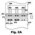
例示的なエアロゾル発生装置、例示的な消耗品、およびそれらの構成要素を、図2〜12に図示および例示する。図2A〜2Bにおいて、例示のエアロゾル発生装置200は、消耗品210とインターフェースしている。図2Aにおいて、エアロゾル発生装置200および消耗品210は隙間を介しており、エアロゾル発生装置200の接触ゾーン201および消耗品210の接触ゾーン211は、平面の表面として表されている。図示の通り、エアロゾル発生装置200は、三つの導体203の対202を含む。導体203のそれぞれは、接触ゾーン201内に位置する結合領域204を含む。言い換えれば、導電線または導体203のアレイ、および結合領域204のアレイがあると記載されうる。導体203は、電子回路209に接続され、そこから結合領域204に延びうる。 An exemplary aerosol generator, exemplary consumables, and components thereof are illustrated and illustrated in FIGS. 2-12. In FIGS. 2A-2B, the
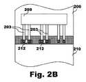
消耗品210の接触ゾーン211上には、一つ以上の導電性部分212がある。導電性部分212のそれぞれは、導電線214によって結合されている、または結合されていない結合領域215を含みうる。図示の通り、消耗品210の接触領域215は、図2Bに示すように消耗品210がエアロゾル発生装置200とインターフェースする時に、消耗品の結合領域215がエアロゾル発生装置200の結合領域204に接触しうる、または触れうるように、エアロゾル発生装置200の結合領域204と整列しうる。 There is one or more
図2Bにおいて、エアロゾル発生装置200の導体203の対202のうちの二つは、消耗品210の導電性部分212によって電気的に結合されている。言い換えれば、エアロゾル発生装置200と消耗品210が接続され、接触ゾーン201、211は、消耗品210の導電性部分212がエアロゾル発生装置200の導体203の一部の結合領域204と重なって導体203の二つの対202を接続するように重なっており、これは、回路209によって検出されうる。 In FIG. 2B, two of the
この、またはその他の実施形態では、エアロゾル発生装置200の電子回路209は、導体203のうちのいずれの対202が一緒に接続されたその電線を有するかを判定することができ、この情報を消耗品210の特性値として使用しうる。エアロゾル発生装置200の構成に応じて、その後この情報は、電子回路209によって直接使用されてもよく(例えば、情報が消耗品210の加熱温度に関連し、電子回路209が消耗品210の加熱プロセスを制御する場合)、または、バスによってエアロゾル発生装置200の別の電子部品に送信されて使用されてもよい(例えば、情報がエアロゾル発生装置200の外部表面上、またはエアロゾル発生装置200に無線接続された携帯電話上に表示される場合)。 In this or other embodiment, the
消耗品の識別に使用するための例示の回路250が図3に図示される。図示の通り、エアロゾル発生装置の電子回路250は、その入力/出力導体または電線254、255、256、257のレベルをチェックするマイクロコントローラ252を含みうる。図中には四つのI/O導体または電線254、255、256、257があるが、この数は実施形態に応じて変動しうることが理解される。消耗品がエアロゾル発生装置に接続されていない場合、これらのI/O導体254、255、256、257は、電圧V+にある。 An
各I/O導体254、255、256、257は、電子回路250内に含まれ、それらと関連付けられる、不連続な導体264、265、266、267の対または組を有する。例えば、一対の導体265は、I/O導体255と関連付けられる、またはI/O導体255に関連する。各I/O導体254、255、256、257は、それらに関連付けられた導体の対264、265、266、267の短絡の場合に、高い状態から低い状態となり(例えば、消耗品の導電性部分に起因して)、この状態変化は、マイクロコントローラ252によって監視されうる。 Each I /
従って、消耗品がエアロゾル発生装置のインターフェースによって受けられた時に、消耗品の導電性部分が回路250の対264、265、266、267のうちの一つ以上と接触して電気的に結合してもよく、マイクロコントローラ252は、消耗品から情報が判定されうるように、対264、265、266、267、次にI/O導体254、255、256、257のうちのいずれが「生きているか」を判定しうる。 Thus, when the consumable is received by the interface of the aerosol generator, the conductive portion of the consumable comes into contact with and electrically coupled with one or more of the
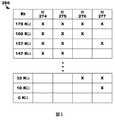
消耗品の識別に使用するためのエアロゾル発生装置の別の例示の回路270が図4に図示される。図示の通り、マイクロコントローラ272は、直列に電気的に結合されたいくつかの抵抗器R1、R2、R3、R4、R5に接続されている。実際には、抵抗器R1、R2、R3、R4、R5を接続するV+電線は、トランジスタおよびマイクロコントローラ272を通って電源に接続されうる。この場合、マイクロコントローラ272は、測定が必要ではない時にはこれらの電線内の電流をカットオフし、電力消費を減少させることが可能となりうる。本実施形態では導体274、275、276、277の四つの対または組が図示されているが、同一の種類の実施形態を使用している間に導体の対の数は変化しうることが理解される。 Another
マイクロコントローラ272から外に出る導体または電線279は、下流へは抵抗器R5に進んで接地(GND)され、上流へは直列のいくつかの抵抗器R1、R2、R3、R4に進み、その結果、これらの4つの抵抗器のそれぞれは、それぞれの不連続な導体274、275、276、277に関連する。例えば、抵抗器R1は、導体274の対に関連しており、これにより、導体274の対が消耗品の導電性部分によって短絡している時に、抵抗器R1が短絡する。 The conductor or
この図では、マイクロコントローラ272は、電線279上の電圧V1を測定することから開始しうる。電力消費を制限するための、本明細書に例示するオプションは、検出前にマイクロコントローラ272によってトランジスタ284をスイッチオンすることである。抵抗器R5の値は既知であるため、循環している電流Iは、I=V1/R5(オームの法則)によって判定されうる。電流を知ることで、ポイント285と286との間の実際の合計上流抵抗Rtは、Rt=(V+)/Iとして判定されうる。直列の上流抵抗器R1、R2、R3、R4のRtは、上流抵抗の合計であるため、それらのそれぞれに対するRtは、抵抗器が短絡していない場合は抵抗器の値に等しく、短絡している時は0に等しい。 In this figure, the
四つの上流抵抗器R1、R2、R3、R4に対して適切な値(抵抗器R1、R2、R3およびR4のそれぞれに対して異なる抵抗値など)を使用することにより、Rtを知ることで、マイクロコントローラ272は、これらの四つの抵抗器R1、R2、R3、R4のうちのいずれが短絡しているかを判定することが可能になりうる。例えば、表または式を使用して、これらの四つの抵抗器R1、R2、R3、R4のうちのいずれが短絡しているかを判定しうる。消耗品の識別に使用するための図4の回路の導体274、275、276、277の対に対応する、例示の合計抵抗値Rtを図示する表280を図5に図示する。図示の通り、表280を使用して、計算された値Rtに応じて、また以下の標準的な抵抗器の値、R1=100K、R2=47K、R3=22K、およびR4=10Kを使用して、導体の対のうちのどれが短絡しているかを判定しうる。表中、「X」は短絡がないことを意味し、「X」がないことは短絡していることを意味する。従って、「X」は、導体の対に電気的に結合された消耗品の導電性部分がないことを意味し、「X」がないことは、消耗品の導電性部分が導体の対に電気的に結合していることを意味する。表280は七つの抵抗Rt値、および関連する短絡または非短絡の組み合わせのみを図示しているが、表は、全ての考えられる合計抵抗Rt値、および導体274、275、276、277の対の関連する短絡または非短絡の組み合わせを含みうる(省略記号で示すように)ことが理解される。 By knowing Rt by using appropriate values for the four upstream resistors R1, R2, R3, R4 (such as different resistance values for each of the resistors R1, R2, R3 and R4), The
上流抵抗器R1、R2、R3およびR4のグループに対する適切な値は、全てのR(i)*W(i)の合計Sを知ることで、各W(i)の値を知ることが可能となるような値であり、ここでR(i)は抵抗器iの上流抵抗値であり、W(i)はランダムに0または1に等しい重みである。例えば、R(i+1)=2*R(i)である場合、全てのR(i)*W(i)の合計Sを知ることで全てのW(i)の値が得られる。W(i)が0に等しい場合、関連する抵抗器は短絡している。 Appropriate values for the groups of upstream resistors R1, R2, R3 and R4 can be obtained by knowing the total S of all R (i) * W (i). Where R (i) is the upstream resistance value of the resistor i and W (i) is a weight randomly equal to 0 or 1. For example, when R (i + 1) = 2 * R (i), all W (i) values can be obtained by knowing the total S of all R (i) * W (i). If W (i) is equal to 0, then the associated resistor is shorted.
さらに、本実施形態では、導体274、275、276、277の連続した対は、直列接続された回路270の性質に起因して、導体を共有しうる。例えば、上流対274、275、276、277の最後の電線が、次の下流対274、275、276、277の最初の線と融合されうる。例えば、対274の導体281は、対275の導体282と融合してもよく、これは、装置上にコンパクトな回路270を生成するのに役立ちうる。 Further, in this embodiment, consecutive pairs of
消耗品の識別に使用するためのエアロゾル発生装置の別の例示の回路290が図6に図示される。図示の通り、回路290は、図4の回路270の変形として図示されており、導体または電線291、292、293は、マイクロコントローラ272から出て上流抵抗器経路へと進み、抵抗器R1、R2、R3、R4のそれぞれの間の電圧差を直接評価する。電圧差が0である場合、それは、抵抗器、従ってそれに関連する導体の対が短絡していることを意味する。例えば、導体279と293との間の電圧差がヌルである場合、それは、電線277の対または組が短絡していることを意味する。こうした実施形態では、短絡は抵抗の合計によってではなく、抵抗器間の電圧の直接評価によって判定されるため、異なる値を有する抵抗器を有することは必須ではない。 Another
例示のエアロゾル発生装置および消耗品は、「キー式」または「非キー式」の結合を有しうる。「キー式」の結合構成では、消耗品は、エアロゾル発生装置内に一方向にのみ接続/差し込まれうる。こうした「キー式」の構成では、エアロゾル発生装置と消耗品とが接続される時に、消耗品の導電性部分の結合領域をどこにするかの配置は、エアロゾル発生装置の結合領域と接触するように、事前に行われており既知である。 Illustrated aerosol generators and consumables may have "key" or "non-key" couplings. In a "key" coupling configuration, consumables can only be connected / inserted in one direction within the aerosol generator. In such a "key" configuration, when the aerosol generator and the consumable are connected, the arrangement of where the coupling region of the conductive part of the consumable is located is in contact with the coupling region of the aerosol generator. , It has been done in advance and is known.
例えば、消耗品上に四対の結合領域C1、C2、C3、C4、および四つのエアロゾル発生装置上に四対の導体のL1、L2、L3、L4がある場合、消耗品をエアロゾル発生装置内に差し込む時、消耗品の結合領域の一部の二つの結合領域間の導電線は、エアロゾル発生装置の導体の対によって判定される短絡回路にある。この場合、エアロゾル発生装置の四つの対の導体について、2 exp(4)=16の考えられる組み合わせがあり(それぞれは短絡している場合もしていない場合もある)、そのため、16の異なるいくつかの情報がエアロゾル発生装置によって消耗品の導電性部分から判定されて、消耗品の特性を識別しうる。 For example, if there are four pairs of coupling regions C1, C2, C3, C4 on the consumable and four pairs of conductors L1, L2, L3, L4 on the four aerosol generators, then the consumables are in the aerosol generator. When plugged into, the conductive wire between the two coupling regions, which is part of the consumable coupling region, is in a short circuit, as determined by the pair of conductors in the aerosol generator. In this case, there are two possible combinations of 2 exp (4) = 16 for the four pairs of conductors in the aerosol generator (each may or may not be short-circuited), so some 16 different. Information can be determined from the conductive portion of the consumable by the aerosol generator to identify the characteristics of the consumable.
消耗品310とインターフェースしている例示のエアロゾル発生装置300の部分透視斜視図が図7に図示される。図示の通り、エアロゾル発生装置300は、「電子たばこ」であってもよく、消耗品310は、カートリッジの内側にあるeリキッドが加熱されうるように、エアロゾル発生装置300内に差し込まれうる、eリキッドを充填されたカートリッジでありうる。消耗品310は、エアロゾル発生装置300とのキー式の接続を有する、または画定してもよく、エアロゾル発生装置300内に差し込まれるようにされる、または構成され、その結果、エアロゾル発生装置300の接触ゾーン301および消耗品310の接触ゾーン311は、消耗品310の導電性部分がエアロゾル発生装置300の一対以上の導体と接触しうるように、接触して一緒に結合される。より具体的には、消耗品310の接触ゾーン311の外側表面が、エアロゾル発生装置300の接触ゾーン301の内側表面と接触して結合されうる。 A partial perspective perspective view of an
さらに、本実施形態では、消耗品310は、接触ゾーン311の側面上に三つの導電性部分312、313、314を含み、これらは、エアロゾル発生装置300上で利用可能な四つの導体の対中、エアロゾル発生装置300の接触ゾーン301上の三対の導体302、303、304を短絡しうる。 Further, in this embodiment, the
消耗品およびエアロゾル発生装置がキー式の接続を有さない実施例では、エアロゾル発生装置と消耗品とが一緒に差し込まれた時に、エアロゾル発生装置のいずれの領域および消耗品のいずれの領域が接触ゾーンにおいて重なりうるかを事前に明確にすることはできない場合がある。こうした実施例において、好ましい実施形態では、エアロゾル発生装置上の導体の対は、エアロゾル発生装置の接触ゾーンの周辺部に沿って規則的なパターンをなしてもよく、その結果、導体の全ての対について、電線の二つの対間の間隔はL1、同一の導体の対の二つの導体間の間隔はL2、そして導体の幅はL3に等しくなる。そのようにすることで、導体の対の二つの導体とこれらの二つの導体のみを接続するために、消耗品上の導電性部分は、長さL=L1+(2xL2)+(3xL3)を有し、これは、以下に示すように、エアロゾル発生装置および消耗品が差し込まれる時のエアロゾル発生装置に対する消耗品のいかなる最終位置にも当てはまる。こうした実施例では、導電性部分の長さはLまたはLの倍数でありうる。導電性部分の長さがnxLである場合、エアロゾル発生装置の導体のn個の対があり、これらは、消耗品の導電性部分によって短絡されうる。 In the embodiment where the consumables and aerosol generator do not have a key connection, when the aerosol generator and consumables are plugged together, either area of the aerosol generator and any area of the consumables come into contact. It may not be possible to clarify in advance whether the zones can overlap. In these embodiments, in a preferred embodiment, the pairs of conductors on the aerosol generator may form a regular pattern along the periphery of the contact zone of the aerosol generator, resulting in all pairs of conductors. The distance between two pairs of wires is equal to L1, the distance between two pairs of the same conductor is L2, and the width of the conductor is equal to L3. By doing so, the conductive portion on the consumable has a length L = L1 + (2xL2) + (3xL3) in order to connect only the two conductors in the pair of conductors and these two conductors. However, this applies to any final position of the consumables with respect to the aerosol generator and consumables when they are plugged in, as shown below. In these examples, the length of the conductive portion can be L or a multiple of L. When the length of the conductive portion is nxL, there are n pairs of conductors of the aerosol generator, which can be short-circuited by the conductive portion of the consumable.
図8に示す通り、エアロゾル発生装置300および消耗品310はわずかに隙間を介しており、エアロゾル発生装置300の接触ゾーン301と消耗品310の接触ゾーン311は、平面の表面として表されている。エアロゾル発生装置300の接触ゾーン301上には、本明細書に示す寸法L1、L2、L3を有する対の導電線302、303、304のアレイがある。消耗品310の接触ゾーン311上には、導電性部分または電線312のアレイがあり、その結果、電線の一部は、長さL=L1+(2xL2)+(3xL3)を有し、それらが、かみ合った時のエアロゾル発生装置300に対する消耗品310の位置に関係なく、導体の対302、303、304のうちの少なくとも一つを短絡させることを可能にする。言い換えれば、いかなる最終位置でも、消耗品310およびエアロゾル発生装置300は、それらの接触ゾーン301、311が接触してかみ合い、エアロゾル発生装置300上の導体の同一の対の二つの導体のみが短絡しうるように、一緒に結合された時に互いに対している。 As shown in FIG. 8, the
こうした実施形態では、エアロゾル発生装置300の電子回路は、短絡した導体の対の数を数えることができ、これは、消耗品310の特性値(例えば、消耗品の識別)を読み取るのに使用されうる情報である。消耗品310の導電性部分または電線がすべて同一の長さLを有する場合、エアロゾル発生装置300上の閉じている導体の対の数は、消耗品310上の導電性部分の数と等しくなりうる。こうした方法で読み取られうる考えられる異なるいくつかの情報(例えば、識別子)は、接触ゾーンの寸法、ならびに、使用される材料およびエアロゾル発生装置装置および消耗品の性質に応じて異なりうる導電性部分の寸法公差に関連する。 In such an embodiment, the electronic circuit of the
エアロゾル発生装置と消耗品との間にキー式の接続がないこうした種類の実施形態の一部の実施例は以下の通りである。第一の実施例では、エアロゾル発生装置物品は、ブレードを加熱する装置であってもよく、これは、消耗品としての役割を果たすたばこスティック内に挿入される。この実施例では、たばこスティックは管状であり、その長軸方向軸に沿った任意の種類の回転後にブレード上に挿入されてもよく、そのため、スティックはエアロゾル発生装置とのキー式の接続を有さない。このような場合、スティックの外側表面上(例えば、消耗品の容器としての役割を果たすスティックのラッピングペーパー上)に置かれた導電性部分または電線、およびエアロゾル発生装置の内側表面における対の導体の対のアレイを備える、示される種類の実施形態が適用されうる。こうした実施形態では、エアロゾル発生装置上の導体は厚くされて、外側表面がわずかに可撓性でありうるたばこスティックとの接触を増大させうる。 Some embodiments of these types of embodiments in which there is no key connection between the aerosol generator and the consumables are as follows. In the first embodiment, the aerosol generator article may be a device that heats the blade, which is inserted into a tobacco stick that acts as a consumable item. In this embodiment, the tobacco stick is tubular and may be inserted onto the blade after any kind of rotation along its longitudinal axis, so the stick has a key connection with an aerosol generator. Do not. In such cases, a conductive portion or wire placed on the outer surface of the stick (eg, on the wrapping paper of the stick that acts as a container for consumables), and a pair of conductors on the inner surface of the aerosol generator. The indicated types of embodiments with a pair of arrays can be applied. In these embodiments, the conductors on the aerosol generator can be thickened to increase contact with the tobacco stick, whose outer surface can be slightly flexible.
消耗品310とインターフェースしている例示のエアロゾル発生装置300が図9に図示される。図示の通り、エアロゾル発生装300は、消耗品310(例えば、たばこスティック)が挿入されてブレードによって加熱されうる、開口部309を有する、または画定する。消耗品310は、容器としての役割を果たす、外側表面上のラッピングペーパー319と、エアロゾル発生装置300の開口部309の内側表面上にある導体308の対を短絡させうる、ラッピングペーパー319上の導電性部分または電線318とを含みうる。これらの導電性部分318は、非キー式の接続について上で示した特性を有する。エアロゾル発生装置300の電子回路によって読み取られる、導体308の対の短絡の数は、消耗品310についての情報をエアロゾル発生装置300に与えうる。 An
第二の実施例では、消耗品は、容器としての役割を果たすボトルからのeリキッドを使用してもよく、エアロゾル発生装置は、eリキッドが中に注がれる特定のタンクを有してもよい。eリキッドを有するがカートリッジは有さない、このような場合には、例えば、eリキッドについての最良の加熱プロファイルを自動的に発見するためのエアロゾル発生装置と消耗品との間の接続は、エアロゾル発生装置上に、ボトルの開口部またはボトルキャップ(例えば、これらは共に通常丸く、そのため、非キー式の実施形態をエアロゾル発生装置で使用しうる)の様な、消耗品のボトルの一部上に接続/差し込まれうる特定の領域(例えば、eリキッド用の開口部)を有することによって行われうる。 In a second embodiment, the consumable may use an e-liquid from a bottle that acts as a container, and the aerosol generator may have a specific tank into which the e-liquid is poured. Good. With the e-liquid but not the cartridge, in such cases, for example, the connection between the aerosol generator and the consumables to automatically find the best heating profile for the e-liquid is the aerosol. On the generator, on a portion of the consumable bottle, such as a bottle opening or a bottle cap (eg, both are usually round, so non-key embodiments can be used in the aerosol generator). This can be done by having a specific area (eg, an opening for an e-liquid) that can be connected / inserted into the.
消耗品が消耗品の容器の内側の構成要素によって加熱され、エアロゾル発生装置と消耗品との間のキー式の接続または非キー式の接続を備える、エアロゾル発生装置によって給電されるその他の実施形態によれば、消耗品上の導電性部分の少なくとも一つは、消耗品のエアロゾル形成基体のヒーターとしての役割を果たす構成要素に電気的に結合されうる。こうした構成要素は、例えば、ジュールの法則/抵抗によるメッシュ加熱でありうる。こうした実施形態では、エアロゾル発生装置の全体的な機能は変化しない(例えば、エアロゾル発生装置が電力を提供して消耗品の構成要素を加熱しうる)が、本明細書に記載の器具、装置、および方法を使用する際、ヒーターはまた、消耗品の識別工程の一部であってもよい。 Other embodiments in which the consumable is heated by a component inside the container of the consumable and powered by the aerosol generator, comprising a keyed or non-keyed connection between the aerosol generator and the consumable. According to this, at least one of the conductive parts on the consumable can be electrically coupled to a component that acts as a heater for the aerosol-forming substrate of the consumable. Such a component can be, for example, mesh heating by Joule heating / resistance. In these embodiments, the overall function of the aerosol generator does not change (eg, the aerosol generator may provide power to heat the components of the consumable), but the appliances, devices, described herein. And when using the method, the heater may also be part of the consumables identification process.
一つ以上のこうした実施形態では、エアロゾル発生装置の導体の対のアレイのすべての導体は、消耗品の少なくとも一つの導電性部分に接続された少なくとも一つのヒーターを使用して消耗品を加熱しうること専用の「電力線」(例えば、ヒーター等の受電装置に電力を送達するために電気を伝達するように構成された導体)でありうる。一つ以上の実施形態では、ヒーターに接続されていない消耗品の導電性部分は、識別の目的のために短絡していても短絡していなくてもよく、導電性部分の少なくとも一つは、エアロゾル発生装置の導体に結合されて、エアロゾル発生装置からヒーターに電力を運びうる。言い換えれば、消耗品の導電性部分は、少なくともヒーターに接続されて、それらに接続されたエアロゾル発生装置の導体の対上に電圧を発生しうる。こうした電圧は、エアロゾル発生装置の電子回路によって検出されうるが、その値はまた、消耗品の識別に関与しうる。消耗品の(または消耗品の特性)識別は、短絡したエアロゾル発生装置の導体の対、それらの間に電圧を有する導体の対(例えば、一つ以上のヒーター、ならびに場合によっては電圧の値を示す)、ならびに切断された一対の導体をチェックすることによって完了しうる。 In one or more of these embodiments, all conductors in a pair of array of conductors in the aerosol generator heat the consumables using at least one heater connected to at least one conductive portion of the consumables. It can be a dedicated "power line" (eg, a conductor configured to transmit electricity to deliver power to a power receiving device such as a heater). In one or more embodiments, the conductive parts of the consumable that are not connected to the heater may or may not be short-circuited for identification purposes, and at least one of the conductive parts is It can be coupled to the conductor of the aerosol generator to carry power from the aerosol generator to the heater. In other words, the conductive parts of the consumable can at least be connected to the heater and generate a voltage on the opposite side of the conductor of the aerosol generator connected to them. Such voltages can be detected by the electronic circuitry of the aerosol generator, but their values can also contribute to the identification of consumables. Consumables (or consumables characteristics) identification is a pair of conductors in a short-circuited aerosol generator, a pair of conductors with a voltage between them (eg, one or more heaters, and possibly a voltage value). Shown), as well as by checking a pair of cut conductors.
こうした構成は、こうした喫煙物品の全体的なアーキテクチャが、エアロゾル発生装置からの電力を使用しうる、一つ以上のヒーターを消耗品内にすでに有しうるように設計されうる。このように、所期の通りに(例えば、消耗品を加熱するために)機能する間のヒーターはまた、消耗品についての情報をエアロゾル発生装置に伝送するように機能しうる。 Such configurations may be designed so that the overall architecture of these smoking items can already have one or more heaters in the consumable that can use the power from the aerosol generator. Thus, the heater while functioning as expected (eg, to heat the consumables) can also function to transmit information about the consumables to the aerosol generator.
消耗品の一部としてのヒーター、および消耗品とエアロゾル発生装置との間にキー付きの接続を備えた別の実施形態では、エアロゾル発生装置の導体の対の二つの導体が融合し、消耗品の導電性部分の結合領域が融合してもよく、エアロゾル発生装置が消耗品に接続された時に、消耗品の少なくとも一つのヒーター構成要素が、エアロゾル発生装置の少なくとも一つの導体をエアロゾル発生装置の別の導体に接続しうる。この少なくとも一つのヒーター構成要素の位置が消耗品(例えば、および容器)によって異なりうるため、接続されているエアロゾル発生装置の導体の対によって示される(およびエアロゾル発生装置の電子回路によって検出されうる)ように、ヒーター位置は、ヒーターがそれらから期待されるように消耗品を加熱する間、消耗品の識別としての役割を果たしうる。 In another embodiment with a heater as part of the consumable and a keyed connection between the consumable and the aerosol generator, the two conductors of the pair of conductors of the aerosol generator are fused and consumable. The coupling regions of the conductive parts of the consumable may be fused, and when the aerosol generator is connected to the consumable, at least one heater component of the consumable will connect at least one conductor of the aerosol generator to the aerosol generator. Can be connected to another conductor. The location of this at least one heater component can vary by consumable (eg, and container) and is therefore indicated by a pair of conductors of the attached aerosol generator (and can be detected by the aerosol generator's electronics). As such, the heater position can serve as an identification of the consumables while the heater heats the consumables as expected from them.
消耗品410とインターフェースしている例示のエアロゾル発生装置400の部分透視斜視図が図10に図示される。図示の通り、消耗品410は、eリキッドを充填されたカートリッジであり、これは、エアロゾル発生装置400に対するキー式の接続を有し、また、消耗品410は、エアロゾル発生装置400とインターフェースする、またはエアロゾル発生装置400内に差し込まれるように作製されて、その結果、エアロゾル発生装置400の接触ゾーン401および消耗品410の接触ゾーン411が接触して一緒に結合されうる。本図は、四つの電力導体または電線を示しており、これらのうちの二つはエアロゾル発生装置400上の403、405として標識されているが、その他の実施形態は、より多くの、またはより少ない電力導体を有してもよい。 A partial perspective perspective view of an
図示の通り、消耗品410は、ヒーター440に電気的に接続された二つの導電性部分または結合領域412、413を有し、これらは、消耗品410がエアロゾル発生装置400内に差し込まれた時にエアロゾル発生装置400の二つの電力導体403、405と電気的に結合されて接触しうる。そのようにする場合、エアロゾル発生装置400の電力導体403、405が、消耗品410の導電性部分412、413を介してヒーター440にエネルギーを提供してもよく、開いている、エアロゾル発生装置400のその他の電力線に対する電力導体403、405上にヒーター440によって発生した電圧により、エアロゾル発生装置400が、消耗品410の識別として使用されうるヒーター440の位置を識別することが可能となりうる。 As shown, the consumable 410 has two conductive portions or
消耗品410の識別に使用するためのエアロゾル発生装置400の例示の回路430の図が図11に図示される。図示の通り、エアロゾル発生装置400の回路430は、エアロゾル発生装置400と本実施形態ではヒーター440を含む消耗品410とが接続される時に、四つの電力導体402、403、404、405と、これらの電力線の二つ(ヒーター440を導体403、405に結合する点線によって示す)に接続されたヒーター440とを含む。 FIG. 11 shows a diagram of an
ヒーター440の位置をチェックする時、エアロゾル発生装置400のマイクロコントローラ408は、トランジスタT1、T2、T3、T4を使用して、起動された電線の電圧をチェックする間に電力コンダクタまたは電線402、403、404、405を二つずつ連続的に起動しうる。回路430はさらに、電力導線または電線402、403、404、405のそれぞれに対するI/O電線422、423、424、425を含みうる。I/O電線422、423、424、425は、導体または電線402、403、404、405のそれぞれおよびマイクロコントローラ408に電気的に結合されうる。マイクロコントローラ408は、I/O電線422、423、424、425を使用して、電力導線402、403、404、405がヒーター440に接続される時を判定しうる。例えば、導体403、405を起動し、そのI/O電線423、425を介してそれらの電圧をチェックする時、マイクロコントローラ408は、本図において点線を使用して示すように、導体403、405がヒーター440に電気的に結合されているため、ヒーター440に対応する電圧差を検出しうる。マイクロコントローラ408は、電力線402、403、404、405のうちのいずれにヒーター440が接続されるかによって示される、ヒーター440の位置を、消耗品410の識別として使用しうる。 When checking the position of the
消耗品410の識別に使用するためのエアロゾル発生装置400の別の例示の回路431の図が図12に図示されており、図12は、電力線402、403、404、405の二つのエンドポイント間の抵抗値を評価することによってヒーター440を検出する別の方法を示している。 A diagram of another
図示の通り、ヒーター440の一方の側が装置の接地(GND)に接続されてもよく、ヒーター440の他方の側が電力導体または電線402、403、404、405のうちの一つに選択的に接続されうる。この図では、ヒーター440は、点線によって示すように、導体403に接続されている。この変形は、電子回路に対して、T1、T2、T3、T4の任意のシーケンスがヒーター440の接触位置を検出することを回避するという利点を提供する。この場合、マイクロコントローラ408は、すべてのトランジスタをスイッチ「オン」してヒーター440に電力を供給し、電線422、423、424、425上の電圧を直接測定して、導体402、403、404、405のうちのいずれがヒーター440に接続されているかを識別しうる。従って、ヒーターの位置は基本的に、電力が伝送されてエアロゾルが発生し始めるとの同時に識別されうる。 As shown, one side of the
その他の用途は、喫煙物品が内側に電子回路を有さないが消耗品を使用している場合、または喫煙物品自体が消耗品である(例えば、熱源を使用する喫煙物品)時に、喫煙物品の付属品であるエアロゾル発生装置におけるものでありうる。こうした実施例では、エアロゾル発生装置は、示される電子回路のうちの一つ、および消耗品をその中に差し込むことを可能にする形状を有しうる。エアロゾル発生装置はさらに、自己作動装置であってもよく、または、携帯電話のような別の電子装置に差し込み可能であって、消耗品の容器上で読み取られるように、消耗品についての情報を読み取って登録してもよい。例えば、ユーザーの携帯電話を介してソーシャルネットワーク上で消費者の使用または選択を示すのに使用されうる。 Other uses include when the smoking article does not have an electronic circuit inside but uses consumables, or when the smoking article itself is a consumable (eg, a smoking article that uses a heat source). It can be in the aerosol generator that is an accessory. In these embodiments, the aerosol generator may have a shape that allows one of the indicated electronic circuits and consumables to be inserted therein. The aerosol generator may also be a self-actuating device, or it can be plugged into another electronic device such as a mobile phone and provides information about the consumable so that it can be read on the consumable container. You may read and register. For example, it can be used to indicate consumer use or choice on social networks via a user's mobile phone.
図13を参照すると、本発明による例示のシステム500が図示される。システム500は、ユーザーインターフェース装置501およびエアロゾル発生装置600を含む。ユーザーインターフェース装置501は、コントローラ502および関連するデータストレージ503を含む。データストレージ503は、例えば、エアロゾル発生装置600およびそれによって使用される消耗品に関連する情報の伝送のための、エアロゾル発生装置600とインターフェースする消耗品を表すデータの取得のためのプログラムおよびルーチンなどのプログラムおよびルーチン504、および本明細書に記載の例示の方法および工程を実行するための任意のその他のプログラムまたはルーチンを含む。データストレージ503は、消耗品に関するデータ、消耗品のシリアル番号を追加的な情報にリンク付けするデータ、様々なタイプの消耗品にリンク付けされた消耗品についての情報等などのデータ505をさらに含む。ユーザーインターフェース装置501は、ユーザーがインタラクト可能なグラフィカルユーザーインターフェースを備えるディスプレイ506をさらに含む。 With reference to FIG. 13, an
エアロゾル発生装置600は、それによって使用される消耗品に関する情報をユーザーインターフェース装置501に伝送しうる。例えば、エアロゾル発生装置600は、それによって使用される一つ以上の消耗品の、シリアル番号、タイプ、使用期限等のうちの一つ以上をユーザーインターフェース装置501に伝送しうる。一実施形態では、エアロゾル発生装置600は、消耗品とのインターフェース、および本明細書に記載の器具および工程を使用した消耗品の識別に応答して、こうした情報をユーザーインターフェース装置501に伝送しうる。さらに、ユーザーインターフェース装置501は、エアロゾル発生装置600および消耗品に関する情報を、その他の装置または器具に、例えば、インターネット(外部データベースサーバ650など)上で伝送しうる。データベースサーバ650は、消耗品およびエアロゾル発生装置600に関する情報をユーザーインターフェース装置601に伝送しうる。 The
例えば、消耗品は、エアロゾル発生装置600とインターフェースしてもよく、エアロゾル発生装置600は、本明細書に記載の器具および工程を使用して消耗品のタイプを識別しうる。その後、エアロゾル発生装置600は、エアロゾル発生装置600によって使用されている消耗品のタイプをユーザーインターフェース装置501にアップロードまたは伝送してもよく、ユーザーインターフェース装置501は、こうしたデータに対して一つ以上のアクションを実施しうる。例えば、理想的な電力設定、風味剤、ニコチン濃度等の、ユーザーインターフェース装置501がメモリに保存した、例えば、消耗品のタイプおよびその他の情報などの消耗品に関する様々な情報が、ユーザーインターフェース装置501のユーザーインターフェース506上に表示されうる。また、ユーザーインターフェース装置501が、メモリ内に記憶された、識別された消耗品についての情報を有さない場合があり、そしてそれ故にデータベースサーバ650を参考にする場合がある。例えば、ユーザーインターフェース装置501が、消耗品のタイプをデータベースサーバ650に伝送し、データベースサーバ650が、消耗品に関する情報をユーザーインターフェース装置501に戻してもよい。 For example, the consumable may interface with the
従って、エアロゾル生成消耗品の識別に使用するための器具、装置、および方法が記載される。本発明の様々な修正および変形が、本発明の範囲および精神を逸脱することなく、当業者に明らかになるであろう。特定の好ましい実施形態に関連して本発明を説明してきたが、当然のことながら、特許請求する通りの本発明は、こうした特定の実施形態に不当に限定されるべきではない。実際に、コンピュータ技術、電子技術およびエアロゾル発生装置製造または関連分野の当業者にとって明らかである、本発明を実行するための記述された方法の様々な修正は、以下の特許請求の範囲の範囲内に収まるものであることが意図される。 Therefore, instruments, devices, and methods for use in identifying aerosol-producing consumables are described. Various modifications and variations of the present invention will be apparent to those skilled in the art without departing from the scope and spirit of the present invention. Although the present invention has been described in the context of certain preferred embodiments, it should not be unreasonably limited to these particular embodiments, as claimed. In fact, various modifications of the described method for carrying out the present invention, which are apparent to those skilled in the art of computer technology, electronic technology and aerosol generator manufacturing or related fields, are within the scope of the following claims. It is intended to fit in.
Claims (24)
Translated fromJapaneseエアロゾル生成基体と、
消耗品のタイプに応じて前記消耗品の周りの異なる位置に位置付けられて前記消耗品を識別する、一つ以上の導電性部分と、を備える、消耗品。Consumables for use in aerosol generators
Aerosol generation substrate and
A consumable that comprises one or more conductive portions that are located at different locations around the consumable to identify the consumable depending on the type of consumable.
消耗品の少なくとも一部分を受けるためのインターフェースであって、前記消耗品がエアロゾル生成基体と前記消耗品を識別する一つ以上の導電性部分と、を含む、インターフェースと、
一つ以上の回路の少なくとも一部分を画定する一対以上の導体であって、前記一対以上の導体が、前記消耗品が前記インターフェースによって受けられた時に、前記消耗品の前記一つ以上の導電性部分と選択的に電気的に結合可能である、一対以上の導体と、
一つ以上のプロセッサを含み、前記一対以上の導体に動作可能に結合されるコントローラであって、前記コントローラが、前記消耗品が前記インターフェースによって受けられた時に、前記一対以上の導体と前記一つ以上の導電性部分とによって画定される前記一つ以上の回路の完成に基づいて前記消耗品を識別するように構成される、コントローラと、を備える、エアロゾル発生装置。Aerosol generator
An interface for receiving at least a portion of a consumable, wherein the consumable comprises an aerosol-generating substrate and one or more conductive portions that identify the consumable.
A pair or more of conductors defining at least a portion of one or more circuits, wherein the pair or more of the conductors are the one or more conductive portions of the consumable when the consumable is received by the interface. With a pair or more of conductors that can be selectively electrically coupled with
A controller that includes one or more processors and is operably coupled to the pair or more conductors, wherein the controller and the pair or more conductors and the one when the consumables are received by the interface. An aerosol generator comprising a controller configured to identify the consumables based on the completion of the one or more circuits defined by the conductive portions.
エアロゾル発生装置のインターフェースを使用して消耗品を受けることであって、前記消耗品がエアロゾル生成基体と前記消耗品を識別する一つ以上の導電性部分と、を含む、受けることと、
前記消耗品が前記エアロゾル発生装置の前記インターフェースによって受けられた時に、前記エアロゾル発生装置の一対以上の導体と前記消耗品の前記一つ以上の導電性部分とによって画定される一つ以上の回路の完成に基づいて前記消耗品を識別することと、を含む、方法。A way to identify consumables
Receiving consumables using the interface of an aerosol generator, wherein the consumables include an aerosol-generating substrate and one or more conductive portions that identify the consumables.
Of one or more circuits defined by a pair or more of conductors of the aerosol generator and one or more conductive portions of the consumable when the consumable is received by the interface of the aerosol generator. A method comprising identifying said consumables based on completion.
Priority Applications (1)
| Application Number | Priority Date | Filing Date | Title |
|---|---|---|---|
| JP2023169284AJP2023169418A (en) | 2017-09-08 | 2023-09-29 | Consumable identification |
Applications Claiming Priority (3)
| Application Number | Priority Date | Filing Date | Title |
|---|---|---|---|
| EP17190202 | 2017-09-08 | ||
| EP17190202.6 | 2017-09-08 | ||
| PCT/EP2018/072262WO2019048211A1 (en) | 2017-09-08 | 2018-08-16 | Consumable identification |
Related Child Applications (1)
| Application Number | Title | Priority Date | Filing Date |
|---|---|---|---|
| JP2023169284ADivisionJP2023169418A (en) | 2017-09-08 | 2023-09-29 | Consumable identification |
Publications (3)
| Publication Number | Publication Date |
|---|---|
| JP2020532973Atrue JP2020532973A (en) | 2020-11-19 |
| JP2020532973A5 JP2020532973A5 (en) | 2021-09-24 |
| JP7360383B2 JP7360383B2 (en) | 2023-10-12 |
Family
ID=59846437
Family Applications (2)
| Application Number | Title | Priority Date | Filing Date |
|---|---|---|---|
| JP2020511955AActiveJP7360383B2 (en) | 2017-09-08 | 2018-08-16 | Identification of consumables |
| JP2023169284APendingJP2023169418A (en) | 2017-09-08 | 2023-09-29 | Consumable identification |
Family Applications After (1)
| Application Number | Title | Priority Date | Filing Date |
|---|---|---|---|
| JP2023169284APendingJP2023169418A (en) | 2017-09-08 | 2023-09-29 | Consumable identification |
Country Status (11)
| Country | Link |
|---|---|
| US (3) | US11185112B2 (en) |
| EP (1) | EP3678501B1 (en) |
| JP (2) | JP7360383B2 (en) |
| KR (1) | KR102670644B1 (en) |
| CN (2) | CN111031823B (en) |
| IL (1) | IL272285B2 (en) |
| MY (1) | MY208375A (en) |
| PH (1) | PH12020500082A1 (en) |
| PL (1) | PL3678501T3 (en) |
| TW (1) | TWI787316B (en) |
| WO (1) | WO2019048211A1 (en) |
Cited By (4)
| Publication number | Priority date | Publication date | Assignee | Title |
|---|---|---|---|---|
| JP2023515830A (en)* | 2021-02-08 | 2023-04-14 | ケーティー アンド ジー コーポレイション | aerosol generator |
| JPWO2023112149A1 (en)* | 2021-12-14 | 2023-06-22 | ||
| JP2023169418A (en)* | 2017-09-08 | 2023-11-29 | フィリップ・モーリス・プロダクツ・ソシエテ・アノニム | Consumable identification |
| US12036360B2 (en) | 2018-03-29 | 2024-07-16 | Nicoventures Trading Limited | Control device for an electronic aerosol provision system |
Families Citing this family (17)
| Publication number | Priority date | Publication date | Assignee | Title |
|---|---|---|---|---|
| BR112020018379A2 (en) | 2018-04-10 | 2020-12-29 | Philip Morris Products S.A. | AEROSOL GENERATOR ARTICLE UNDERSTANDING A HEATABLE ELEMENT |
| EP3876761A1 (en) | 2018-11-05 | 2021-09-15 | Juul Labs, Inc. | Cartridges for vaporizer devices |
| BR112021012288A2 (en)* | 2019-01-25 | 2021-08-31 | Philip Morris Products S.A. | SHISHA CARTRIDGE WITH LID |
| GB2586255A (en)* | 2019-08-14 | 2021-02-17 | E Breathe Ltd | Improvements relating to aerosol generating systems |
| CN110547514A (en)* | 2019-09-16 | 2019-12-10 | 深圳雾芯科技有限公司 | Atomization device |
| WO2021053165A1 (en)* | 2019-09-18 | 2021-03-25 | Jt International S.A. | Display bar graph and adaptive control |
| KR20210039199A (en) | 2019-10-01 | 2021-04-09 | 주식회사 케이티앤지 | Aerosol generating device including display |
| CN111248504B (en) | 2019-12-24 | 2023-04-07 | 深圳麦克韦尔科技有限公司 | Atomizer identification circuit of electronic atomization device and related device |
| GB202001674D0 (en)* | 2020-02-07 | 2020-03-25 | Nicoventures Trading Ltd | Aerosol provision system |
| CN213549672U (en)* | 2020-08-12 | 2021-06-29 | 深圳市为美电子科技有限公司 | Electronic atomization device |
| CN112806612A (en)* | 2021-01-11 | 2021-05-18 | 东莞市麦斯莫科电子科技有限公司 | Power supply host and electron cigarette of applicable multiple heater |
| WO2022268807A1 (en)* | 2021-06-22 | 2022-12-29 | Jt International S.A. | Aerosol generating device comprising a switch portion, and associated removable cartridge and aerosol generating set |
| GB202115192D0 (en)* | 2021-10-22 | 2021-12-08 | Nicoventures Trading Ltd | Aerosol provision system |
| CN114010269A (en)* | 2021-11-08 | 2022-02-08 | 江苏朴芃医疗科技有限公司 | Consumable management system, management method and vascular calcification treatment equipment |
| CN114343251A (en)* | 2022-01-17 | 2022-04-15 | 东莞市阿尔法电子科技有限公司 | Short-circuit protection method for atomization device and atomization device |
| KR20240170807A (en)* | 2022-04-01 | 2024-12-04 | 제이티 인터내셔널 소시에떼 아노님 | Steam generation system |
| US20230346041A1 (en)* | 2022-04-29 | 2023-11-02 | Rai Strategic Holdings, Inc. | Consumable identification and power control |
Citations (6)
| Publication number | Priority date | Publication date | Assignee | Title |
|---|---|---|---|---|
| JP2002229722A (en)* | 2001-01-17 | 2002-08-16 | Nokia Corp | Keyboard, keyboard arrangement method, and electronic device |
| EP2399636A1 (en)* | 2010-06-23 | 2011-12-28 | Philip Morris Products S.A. | An improved aerosol generator and liquid storage portion for use with the aerosol generator |
| US20150101625A1 (en)* | 2013-10-10 | 2015-04-16 | Kyle D. Newton | Electronic Cigarette with Encoded Cartridge |
| WO2016143079A1 (en)* | 2015-03-10 | 2016-09-15 | 日本たばこ産業株式会社 | Method of manufacturing atomizing unit, non-combustion type flavor inhaler, atomizing unit, and atomizing unit package |
| JP2017501682A (en)* | 2013-12-03 | 2017-01-19 | フィリップ・モーリス・プロダクツ・ソシエテ・アノニム | An aerosol generating article incorporating a taggant and an electrically operated system |
| WO2017084849A1 (en)* | 2015-11-17 | 2017-05-26 | Philip Morris Products S.A. | Cartridge for an aerosol-generating system with customizable identification resistance |
Family Cites Families (19)
| Publication number | Priority date | Publication date | Assignee | Title |
|---|---|---|---|---|
| US5302935A (en)* | 1992-12-08 | 1994-04-12 | Eastman Kodak Company | Renewable gas sensor, renewable gas sensor base and method for renewing a gas sensor |
| US6217168B1 (en) | 1999-02-24 | 2001-04-17 | Hewlett-Packard Company | Transparency detection in a tray |
| JP2002229772A (en) | 2001-02-06 | 2002-08-16 | Sony Corp | Sort processing method and sort processor |
| US6904365B2 (en)* | 2003-03-06 | 2005-06-07 | Schlumberger Technology Corporation | Methods and systems for determining formation properties and in-situ stresses |
| WO2004110524A2 (en) | 2003-06-06 | 2004-12-23 | Phacor, Inc. | Fluid-flow cassette for an ophthalmic surgical instrument |
| EP2201850A1 (en)* | 2008-12-24 | 2010-06-30 | Philip Morris Products S.A. | An article including identification information for use in an electrically heated smoking system |
| US20130284192A1 (en) | 2012-04-25 | 2013-10-31 | Eyal Peleg | Electronic cigarette with communication enhancements |
| US9854841B2 (en)* | 2012-10-08 | 2018-01-02 | Rai Strategic Holdings, Inc. | Electronic smoking article and associated method |
| US10058122B2 (en)* | 2012-10-25 | 2018-08-28 | Matthew Steingraber | Electronic cigarette |
| US20140123989A1 (en) | 2012-11-05 | 2014-05-08 | The Safe Cig, Llc | Device and method for vaporizing a fluid |
| US10154691B2 (en) | 2012-11-26 | 2018-12-18 | Nu Mark Innovations Ltd. | Bonding for an electronic cigarette cartridge |
| US10031183B2 (en) | 2013-03-07 | 2018-07-24 | Rai Strategic Holdings, Inc. | Spent cartridge detection method and system for an electronic smoking article |
| US10039321B2 (en)* | 2013-11-12 | 2018-08-07 | Vmr Products Llc | Vaporizer |
| PL3119224T3 (en)* | 2014-03-21 | 2023-10-23 | Nicoventures Trading Limited | Apparatus for heating smokable material and a method of identifying an article of smokable material |
| GB201423315D0 (en)* | 2014-12-29 | 2015-02-11 | British American Tobacco Co | Apparatus for heating smokable material |
| US10966460B2 (en)* | 2015-07-17 | 2021-04-06 | Rai Strategic Holdings, Inc. | Load-based detection of an aerosol delivery device in an assembled arrangement |
| US10575561B2 (en)* | 2015-11-17 | 2020-03-03 | Altria Client Services Llc | Cartridge for an aerosol-generating system with customizable identification resistance |
| US11160936B2 (en)* | 2017-06-23 | 2021-11-02 | Altria Client Services Llc | Non-combustible vaping device |
| TWI787316B (en)* | 2017-09-08 | 2022-12-21 | 瑞士商菲利浦莫里斯製品股份有限公司 | Aerosol-generating device, non-transitory computer readable storage medium and method of identifying a consumable |
- 2018
- 2018-08-06TWTW107127225Apatent/TWI787316B/enactive
- 2018-08-16CNCN201880052770.7Apatent/CN111031823B/enactiveActive
- 2018-08-16KRKR1020207005462Apatent/KR102670644B1/enactiveActive
- 2018-08-16EPEP18752519.1Apatent/EP3678501B1/enactiveActive
- 2018-08-16MYMYPI2020000388Apatent/MY208375A/enunknown
- 2018-08-16CNCN202410240523.7Apatent/CN117859960A/enactivePending
- 2018-08-16JPJP2020511955Apatent/JP7360383B2/enactiveActive
- 2018-08-16WOPCT/EP2018/072262patent/WO2019048211A1/ennot_activeCeased
- 2018-08-16PLPL18752519Tpatent/PL3678501T3/enunknown
- 2018-12-12USUS16/217,518patent/US11185112B2/enactiveActive
- 2020
- 2020-01-10PHPH12020500082Apatent/PH12020500082A1/enunknown
- 2020-01-27ILIL272285Apatent/IL272285B2/enunknown
- 2021
- 2021-11-24USUS17/535,055patent/US12193518B2/enactiveActive
- 2023
- 2023-09-29JPJP2023169284Apatent/JP2023169418A/enactivePending
- 2024
- 2024-12-09USUS18/973,399patent/US20250098788A1/enactivePending
Patent Citations (6)
| Publication number | Priority date | Publication date | Assignee | Title |
|---|---|---|---|---|
| JP2002229722A (en)* | 2001-01-17 | 2002-08-16 | Nokia Corp | Keyboard, keyboard arrangement method, and electronic device |
| EP2399636A1 (en)* | 2010-06-23 | 2011-12-28 | Philip Morris Products S.A. | An improved aerosol generator and liquid storage portion for use with the aerosol generator |
| US20150101625A1 (en)* | 2013-10-10 | 2015-04-16 | Kyle D. Newton | Electronic Cigarette with Encoded Cartridge |
| JP2017501682A (en)* | 2013-12-03 | 2017-01-19 | フィリップ・モーリス・プロダクツ・ソシエテ・アノニム | An aerosol generating article incorporating a taggant and an electrically operated system |
| WO2016143079A1 (en)* | 2015-03-10 | 2016-09-15 | 日本たばこ産業株式会社 | Method of manufacturing atomizing unit, non-combustion type flavor inhaler, atomizing unit, and atomizing unit package |
| WO2017084849A1 (en)* | 2015-11-17 | 2017-05-26 | Philip Morris Products S.A. | Cartridge for an aerosol-generating system with customizable identification resistance |
Cited By (7)
| Publication number | Priority date | Publication date | Assignee | Title |
|---|---|---|---|---|
| JP2023169418A (en)* | 2017-09-08 | 2023-11-29 | フィリップ・モーリス・プロダクツ・ソシエテ・アノニム | Consumable identification |
| US12036360B2 (en) | 2018-03-29 | 2024-07-16 | Nicoventures Trading Limited | Control device for an electronic aerosol provision system |
| US12280206B2 (en) | 2018-03-29 | 2025-04-22 | Nicoventures Trading Limited | Control device for an electronic aerosol provision system |
| JP2023515830A (en)* | 2021-02-08 | 2023-04-14 | ケーティー アンド ジー コーポレイション | aerosol generator |
| JP7493049B2 (en) | 2021-02-08 | 2024-05-30 | ケーティー アンド ジー コーポレイション | Aerosol Generator |
| JPWO2023112149A1 (en)* | 2021-12-14 | 2023-06-22 | ||
| WO2023112149A1 (en)* | 2021-12-14 | 2023-06-22 | 日本たばこ産業株式会社 | Information processing device, information processing method, and program |
Also Published As
| Publication number | Publication date |
|---|---|
| US12193518B2 (en) | 2025-01-14 |
| RU2020113005A (en) | 2021-10-08 |
| CN117859960A (en) | 2024-04-12 |
| TW201912044A (en) | 2019-04-01 |
| IL272285B2 (en) | 2023-05-01 |
| TWI787316B (en) | 2022-12-21 |
| IL272285B1 (en) | 2023-01-01 |
| CN111031823B (en) | 2024-03-19 |
| KR20200052271A (en) | 2020-05-14 |
| JP2023169418A (en) | 2023-11-29 |
| CN111031823A (en) | 2020-04-17 |
| KR102670644B1 (en) | 2024-05-31 |
| RU2020113005A3 (en) | 2021-12-10 |
| US20190110520A1 (en) | 2019-04-18 |
| EP3678501A1 (en) | 2020-07-15 |
| BR112020002895A2 (en) | 2020-08-04 |
| IL272285A (en) | 2020-03-31 |
| US20220079245A1 (en) | 2022-03-17 |
| US20250098788A1 (en) | 2025-03-27 |
| WO2019048211A1 (en) | 2019-03-14 |
| JP7360383B2 (en) | 2023-10-12 |
| PL3678501T3 (en) | 2022-03-21 |
| MY208375A (en) | 2025-05-02 |
| US11185112B2 (en) | 2021-11-30 |
| EP3678501B1 (en) | 2021-12-01 |
| PH12020500082A1 (en) | 2020-11-09 |
Similar Documents
| Publication | Publication Date | Title |
|---|---|---|
| JP7360383B2 (en) | Identification of consumables | |
| CN109875131A (en) | A kind of electronic cigarette control method, device, electronic cigarette and storage medium | |
| JP7250142B2 (en) | Aerosol generator including detachable heater module | |
| JP2020532973A5 (en) | ||
| JP2022531148A (en) | Decentralized identification storage for tobacco products | |
| KR20190089867A (en) | Product recognition in aerosol generators | |
| KR20180018515A (en) | Product recognition in aerosol generators | |
| CN114269177A (en) | Age verification with registered cartridges of aerosol delivery devices | |
| KR102741094B1 (en) | Aerosol generating device, heating assembly and data interaction method | |
| KR102728486B1 (en) | Aerosol generating device, heating assembly and storage assembly | |
| JP2024170595A (en) | Aerosol generating device having modular components | |
| RU2782783C2 (en) | Consumable part identification | |
| HK40030311B (en) | Consumable identification | |
| CN211861817U (en) | An aerosol generating device and a heating component using the same | |
| BR112020002895B1 (en) | AEROSOL GENERATING DEVICE, METHOD FOR IDENTIFYING A CONSUMABLE AND NON-TRANSIENT COMPUTER READABLE STORAGE MEDIUM | |
| JP2023520713A (en) | Aerosol generator and method of operation | |
| KR102747474B1 (en) | Method for managing design data for tobacco-related article and server operating the method | |
| US20240206557A1 (en) | Method and apparatus for outputting charging information | |
| US20240365879A1 (en) | Control profile managing method and apparatus | |
| US20250082030A1 (en) | Aerosol generating device, aerosol generating system including the same, and method of manufacturing aerosol generating device | |
| TW201944909A (en) | Methods, devices and systems associated with smoking substitute devices | |
| KR20240017843A (en) | Aerosol delivery system |
Legal Events
| Date | Code | Title | Description |
|---|---|---|---|
| A521 | Request for written amendment filed | Free format text:JAPANESE INTERMEDIATE CODE: A523 Effective date:20210812 | |
| A621 | Written request for application examination | Free format text:JAPANESE INTERMEDIATE CODE: A621 Effective date:20210812 | |
| A131 | Notification of reasons for refusal | Free format text:JAPANESE INTERMEDIATE CODE: A131 Effective date:20220914 | |
| A977 | Report on retrieval | Free format text:JAPANESE INTERMEDIATE CODE: A971007 Effective date:20220914 | |
| A521 | Request for written amendment filed | Free format text:JAPANESE INTERMEDIATE CODE: A523 Effective date:20221213 | |
| A131 | Notification of reasons for refusal | Free format text:JAPANESE INTERMEDIATE CODE: A131 Effective date:20230313 | |
| A521 | Request for written amendment filed | Free format text:JAPANESE INTERMEDIATE CODE: A523 Effective date:20230613 | |
| TRDD | Decision of grant or rejection written | ||
| A01 | Written decision to grant a patent or to grant a registration (utility model) | Free format text:JAPANESE INTERMEDIATE CODE: A01 Effective date:20230831 | |
| A61 | First payment of annual fees (during grant procedure) | Free format text:JAPANESE INTERMEDIATE CODE: A61 Effective date:20230929 | |
| R150 | Certificate of patent or registration of utility model | Ref document number:7360383 Country of ref document:JP Free format text:JAPANESE INTERMEDIATE CODE: R150 |