JP2020528001A - A device that conveys haptic feedback, and the components that provide that device. - Google Patents
A device that conveys haptic feedback, and the components that provide that device.Download PDFInfo
- Publication number
- JP2020528001A JP2020528001AJP2019570535AJP2019570535AJP2020528001AJP 2020528001 AJP2020528001 AJP 2020528001AJP 2019570535 AJP2019570535 AJP 2019570535AJP 2019570535 AJP2019570535 AJP 2019570535AJP 2020528001 AJP2020528001 AJP 2020528001A
- Authority
- JP
- Japan
- Prior art keywords
- main body
- cymbal
- actuator
- electrodes
- main
- Prior art date
- Legal status (The legal status is an assumption and is not a legal conclusion. Google has not performed a legal analysis and makes no representation as to the accuracy of the status listed.)
- Pending
Links
Images


Classifications
- H—ELECTRICITY
- H10—SEMICONDUCTOR DEVICES; ELECTRIC SOLID-STATE DEVICES NOT OTHERWISE PROVIDED FOR
- H10N—ELECTRIC SOLID-STATE DEVICES NOT OTHERWISE PROVIDED FOR
- H10N30/00—Piezoelectric or electrostrictive devices
- H10N30/80—Constructional details
- H10N30/87—Electrodes or interconnections, e.g. leads or terminals
- H10N30/871—Single-layered electrodes of multilayer piezoelectric or electrostrictive devices, e.g. internal electrodes
- G—PHYSICS
- G06—COMPUTING OR CALCULATING; COUNTING
- G06F—ELECTRIC DIGITAL DATA PROCESSING
- G06F3/00—Input arrangements for transferring data to be processed into a form capable of being handled by the computer; Output arrangements for transferring data from processing unit to output unit, e.g. interface arrangements
- G06F3/01—Input arrangements or combined input and output arrangements for interaction between user and computer
- G06F3/016—Input arrangements with force or tactile feedback as computer generated output to the user
- G—PHYSICS
- G06—COMPUTING OR CALCULATING; COUNTING
- G06F—ELECTRIC DIGITAL DATA PROCESSING
- G06F3/00—Input arrangements for transferring data to be processed into a form capable of being handled by the computer; Output arrangements for transferring data from processing unit to output unit, e.g. interface arrangements
- G06F3/01—Input arrangements or combined input and output arrangements for interaction between user and computer
- G06F3/03—Arrangements for converting the position or the displacement of a member into a coded form
- G06F3/041—Digitisers, e.g. for touch screens or touch pads, characterised by the transducing means
- G06F3/0414—Digitisers, e.g. for touch screens or touch pads, characterised by the transducing means using force sensing means to determine a position
- H—ELECTRICITY
- H03—ELECTRONIC CIRCUITRY
- H03K—PULSE TECHNIQUE
- H03K17/00—Electronic switching or gating, i.e. not by contact-making and –breaking
- H03K17/94—Electronic switching or gating, i.e. not by contact-making and –breaking characterised by the way in which the control signals are generated
- H03K17/96—Touch switches
- H03K17/964—Piezoelectric touch switches
- H—ELECTRICITY
- H10—SEMICONDUCTOR DEVICES; ELECTRIC SOLID-STATE DEVICES NOT OTHERWISE PROVIDED FOR
- H10N—ELECTRIC SOLID-STATE DEVICES NOT OTHERWISE PROVIDED FOR
- H10N30/00—Piezoelectric or electrostrictive devices
- H10N30/101—Piezoelectric or electrostrictive devices with electrical and mechanical input and output, e.g. having combined actuator and sensor parts
- H—ELECTRICITY
- H10—SEMICONDUCTOR DEVICES; ELECTRIC SOLID-STATE DEVICES NOT OTHERWISE PROVIDED FOR
- H10N—ELECTRIC SOLID-STATE DEVICES NOT OTHERWISE PROVIDED FOR
- H10N30/00—Piezoelectric or electrostrictive devices
- H10N30/50—Piezoelectric or electrostrictive devices having a stacked or multilayer structure
- H10N30/503—Piezoelectric or electrostrictive devices having a stacked or multilayer structure having a non-rectangular cross-section in a plane orthogonal to the stacking direction, e.g. polygonal or circular in top view
- H—ELECTRICITY
- H10—SEMICONDUCTOR DEVICES; ELECTRIC SOLID-STATE DEVICES NOT OTHERWISE PROVIDED FOR
- H10N—ELECTRIC SOLID-STATE DEVICES NOT OTHERWISE PROVIDED FOR
- H10N30/00—Piezoelectric or electrostrictive devices
- H10N30/80—Constructional details
- H10N30/88—Mounts; Supports; Enclosures; Casings
- H—ELECTRICITY
- H01—ELECTRIC ELEMENTS
- H01H—ELECTRIC SWITCHES; RELAYS; SELECTORS; EMERGENCY PROTECTIVE DEVICES
- H01H2215/00—Tactile feedback
- H01H2215/05—Tactile feedback electromechanical
- H01H2215/052—Tactile feedback electromechanical piezoelectric
- H—ELECTRICITY
- H03—ELECTRONIC CIRCUITRY
- H03K—PULSE TECHNIQUE
- H03K2217/00—Indexing scheme related to electronic switching or gating, i.e. not by contact-making or -breaking covered by H03K17/00
- H03K2217/94—Indexing scheme related to electronic switching or gating, i.e. not by contact-making or -breaking covered by H03K17/00 characterised by the way in which the control signal is generated
- H03K2217/96—Touch switches
- H03K2217/96062—Touch switches with tactile or haptic feedback
- H—ELECTRICITY
- H03—ELECTRONIC CIRCUITRY
- H03K—PULSE TECHNIQUE
- H03K2217/00—Indexing scheme related to electronic switching or gating, i.e. not by contact-making or -breaking covered by H03K17/00
- H03K2217/94—Indexing scheme related to electronic switching or gating, i.e. not by contact-making or -breaking covered by H03K17/00 characterised by the way in which the control signal is generated
- H03K2217/965—Switches controlled by moving an element forming part of the switch
- H03K2217/9651—Switches controlled by moving an element forming part of the switch the moving element acting on a force, e.g. pressure sensitive element
- H—ELECTRICITY
- H10—SEMICONDUCTOR DEVICES; ELECTRIC SOLID-STATE DEVICES NOT OTHERWISE PROVIDED FOR
- H10N—ELECTRIC SOLID-STATE DEVICES NOT OTHERWISE PROVIDED FOR
- H10N30/00—Piezoelectric or electrostrictive devices
- H10N30/50—Piezoelectric or electrostrictive devices having a stacked or multilayer structure
- H—ELECTRICITY
- H10—SEMICONDUCTOR DEVICES; ELECTRIC SOLID-STATE DEVICES NOT OTHERWISE PROVIDED FOR
- H10N—ELECTRIC SOLID-STATE DEVICES NOT OTHERWISE PROVIDED FOR
- H10N30/00—Piezoelectric or electrostrictive devices
- H10N30/80—Constructional details
- H10N30/85—Piezoelectric or electrostrictive active materials
- H10N30/853—Ceramic compositions
- H10N30/8548—Lead-based oxides
- H10N30/8554—Lead-zirconium titanate [PZT] based
Landscapes
- Engineering & Computer Science (AREA)
- General Engineering & Computer Science (AREA)
- Theoretical Computer Science (AREA)
- Human Computer Interaction (AREA)
- Physics & Mathematics (AREA)
- General Physics & Mathematics (AREA)
- User Interface Of Digital Computer (AREA)
- Apparatuses For Generation Of Mechanical Vibrations (AREA)
Abstract
Translated fromJapaneseDescription
Translated fromJapanese本発明は、アクティブ(能動的)な触覚フィードバックを生成するためのコンポーネント及びデバイスに関する。これは、ユーザがコンポーネントに力を加えたときにユーザにフィードバックを生成するように構成されたデバイスを含む。そのようなコンポーネントは、ノブ、例えば器具の作動ノブで使用することができる。コンポーネントは、例えばユーザによって行われた設定がコンポーネントによってうまく機能しているという事実をユーザに伝えるために、アクティブな触覚フィードバックを生成することができる。 The present invention relates to components and devices for generating active tactile feedback. This includes devices that are configured to generate feedback to the user when the user exerts force on the component. Such components can be used in knobs, such as instrument actuation knobs. The component can generate active tactile feedback, for example, to inform the user that the settings made by the user are working well with the component.
逆に、コンポーネントはまた、アクティブな触覚フィードバックを与えることができ、例として、携帯電話は、振動アラートを生成することができる。ノートブックなどのモバイル電子デバイス用の触覚型ディスプレイもまた、知られている。触覚フィードバックはまた、力の強さ、又は表面の構成、又は材料の剛性若しくは弾性を触覚的に知覚可能な感覚に変換することができる。 Conversely, components can also provide active tactile feedback, for example, mobile phones can generate vibration alerts. Tactile displays for mobile electronic devices such as notebooks are also known. Tactile feedback can also transform the strength of force, or surface composition, or the stiffness or elasticity of a material into a tactilely perceptible sensation.
本発明の目的は、アクティブな触覚フィードバックを生成するための改善されたデバイスを明確化することである。 An object of the present invention is to clarify an improved device for generating active tactile feedback.
この目的は、特許請求の範囲の請求項1に記載のデバイスによって達成される。本発明の有利な構成は、さらなる請求項から明らかである。 This object is achieved by the device according to claim 1, which is the scope of claims. The advantageous configuration of the present invention is evident from the further claims.
アクティブな触覚フィードバックを生成するためのデバイスが明確化される。フィードバックは、デバイス自体によって生成されるため、アクティブなフィードバックと呼ばれる。フィードバックは、ユーザが自身の感触を介して知覚することができるため、触覚フィードバックとも呼ばれる。 Clarify the device for generating active tactile feedback. Feedback is called active feedback because it is generated by the device itself. Feedback is also called tactile feedback because it can be perceived by the user through his or her own feel.
デバイスは、触覚的に知覚可能なたわみの形でフィードバックを生成するための圧電アクチュエータを備える。アクチュエータは、ほぼ平行平面となっている複数の主表面を有する平坦な圧電型の主本体を備える。第1及び第2のアクチュエータ電極は、主本体に設けられ、圧電アクチュエータの圧電によるたわみは、前記アクチュエータ電極を介してもたらされ得る。 The device comprises a piezoelectric actuator for generating feedback in the form of tactilely perceptible deflection. The actuator comprises a flat piezoelectric main body having a plurality of main surfaces that are substantially parallel planes. The first and second actuator electrodes are provided on the main body, and the piezoelectric deflection of the piezoelectric actuator can be provided via the actuator electrodes.
主本体は、主本体に加えられた力を識別するように構成される。加えられた力は、圧電素子によって電気信号に変換される。この電気信号は、直接、又は適切な場合には、増幅された後にアクチュエータ電極に印加され得る。 The main body is configured to identify the force applied to the main body. The applied force is converted into an electric signal by the piezoelectric element. This electrical signal can be applied directly to the actuator electrodes or, where appropriate, after being amplified.
電圧がアクチュエータ電極に印加された場合、主本体は線膨張を生ずる。線膨張は、法線に対して直角に起こり得、法線は、主本体の主表面に垂直である。このような長さの変化は、横方向収縮とも呼ばれる。この場合、線膨張の方向は、印加された電圧の極性及び圧電材料の分極に依存する。 When a voltage is applied to the actuator electrodes, the main body undergoes linear expansion. Linear expansion can occur at right angles to the normal, which is perpendicular to the main surface of the main body. Such a change in length is also called lateral contraction. In this case, the direction of linear expansion depends on the polarity of the applied voltage and the polarity of the piezoelectric material.
アクチュエータ全体の長さの変化は、好ましくは、加えられた力に平行に、すなわちアクチュエータの主表面の法線に沿って起こる。 The change in length of the entire actuator preferably occurs parallel to the applied force, i.e. along the normal of the actuator's main surface.
xy平面での主本体の横方向収縮は、法線に平行な力を加えるユーザにはほとんど知覚されないため、デバイスは、好適には法線に垂直な方向に沿った主本体の長さの変化を、法線に平行なアクチュエータの線膨張に変換するように構成される。 Since the lateral contraction of the main body in the xy plane is hardly perceived by the user applying a force parallel to the normal, the device preferably changes the length of the main body along the direction perpendicular to the normal. Is configured to convert to linear expansion of the actuator parallel to the normal.
変換は、切頭円錐形状の金属シートが主本体の一方又は両方の主表面に固着されているという事実の存在によって行われ、その金属シートの場合、切頭「円錐頂点」は各々、主表面から離れた方向を向いている。そのような金属シートは、以下ではシンバル形要素とも呼ばれる。 The transformation is carried out by the presence of the fact that a truncated conical metal sheet is attached to one or both main surfaces of the main body, in the case of that metal sheet, each truncated "conical apex" is the main surface. It is facing away from. Such metal sheets are also referred to below as cymbal-shaped elements.
シンバル形要素は、法線に対して垂直方向の主本体の線膨張を、法線に平行な長さの変化に変換するように構成される。シンバル形要素はさらに、主本体の横方向収縮のために生じる法線に平行な主本体の長さの変化を増幅する役割を果たすことができる。円錐台状に曲げられた又は円錐台形状の金属シートは、横方向収縮を吸収することができ、そうすることで、所望の方向、すなわち法線に平行に変形する。この場合、この変形は、同じ方向の圧電によるたわみよりも大きくなることがあり得る。したがって、主本体の両方の主表面上のそれぞれのシンバル形要素により、デバイス全体の長さの十分に知覚可能な変化がもたらされる。 The cymbal element is configured to transform the linear expansion of the main body perpendicular to the normal into a change in length parallel to the normal. The cymbal element can also serve to amplify the change in length of the main body parallel to the normal caused by the lateral contraction of the main body. The truncated cone-shaped or truncated metal sheet can absorb lateral shrinkage, thereby deforming in the desired direction, i.e. parallel to the normal. In this case, this deformation can be greater than the piezoelectric deflection in the same direction. Therefore, each cymbal-shaped element on both main surfaces of the main body provides a fully perceptible variation in the overall length of the device.
シンバル形要素の金属シートがアクチュエータの影響下でかなり弾性的に変形することができるようにするために、シートは、例えばチタンの場合、0.1〜0.4mmの範囲にある典型的な厚さを有するとよい。 In order to allow the metal sheet of the cymbal element to deform fairly elastically under the influence of the actuator, the sheet, for example titanium, has a typical thickness in the range of 0.1-0.4 mm. It is good to have a metal.
シンバル形要素は、平坦な縁部領域を有することができ、これは主本体の主表面の1つに支承され、そこに固着される。固着は、接着剤によって、好ましくはエポキシ含有接着剤に基づいて行われる。 The cymbal-shaped element can have a flat edge region, which is supported and anchored to one of the main surfaces of the main body. The fixation is carried out by an adhesive, preferably on the basis of an epoxy-containing adhesive.
空洞がシンバル形要素の下に囲まれており、その空洞では、シンバル形要素の載置後、又は遅くとも接着剤の熱硬化中(例えば150℃)に過剰な圧力が発生する可能性がある。その場合の前記過剰な圧力は、まだ柔らかい接着剤層から逃げ、そこに膨れをもたらすことがある。膨れを回避するために、シンバル形要素には、孔が設けられる。シンバル形要素の下に囲まれた空洞は、前記孔を介して周囲と連通しており、それにより圧力均等化を行うことができる。しかし、過剰な圧力がなければ、膨れはほとんど回避される。 The cavity is surrounded under the cymbal element, which can generate excessive pressure after the cymbal element is placed or at the latest during thermosetting of the adhesive (eg 150 ° C.). The excess pressure in that case can escape from the still soft adhesive layer and cause swelling there. To avoid bulging, the cymbal-shaped element is provided with holes. The cavity enclosed under the cymbal-shaped element communicates with the surroundings through the hole, whereby pressure equalization can be performed. However, in the absence of excessive pressure, swelling is largely avoided.
比較実験は、孔がアクチュエータの挙動に全く悪影響を及ぼさないことも示している。膨れが防止される利点は、耐久性が向上するため、アクチュエータの信頼性が高くなることである。接着結合は、囲まれた膨れがないため、より耐久性がある。 Comparative experiments also show that the holes have no adverse effect on actuator behavior. The advantage of preventing swelling is increased durability and thus increased reliability of the actuator. Adherens junctions are more durable because there are no enclosed bulges.
アクチュエータは、好適にはベースと固着プレートとの間にある2つのシンバル形要素の切頭円錐部を介して固定される。また、固着プレートは、ベースに接続され、プレストレスによって固定される。プレストレスは、引張又は圧縮応力として作用し、例えば各場合においてばねを介して設定することができる。 The actuator is preferably secured via a truncated cone of two cymbal-shaped elements between the base and the anchoring plate. Also, the fixation plate is connected to the base and fixed by prestress. The prestress acts as a tensile or compressive stress and can be set, for example, via a spring in each case.
一実施形態では、作動プレートは、膜として構成される。膜は、シンバル形要素を固定するように取り付けられ、したがってベースにおいてベースの方向に作用するプレストレスで主本体も固定する。その結果、膜はまた、ベースの方向に引張又は圧縮応力を加える手段として機能する。 In one embodiment, the working plate is configured as a membrane. The membrane is attached to secure the cymbal-shaped element, thus also anchoring the main body with prestress acting in the direction of the base at the base. As a result, the membrane also functions as a means of applying tensile or compressive stress in the direction of the base.
他の実施形態では、作動プレートは、主本体の表面に平行に、したがってベースに平行に向けられ、上部のシンバル形要素のカバー表面に支承され、好ましくは作動プレートに対して自由に移動可能である。作動プレートは、少なくとも2つの側で、より良好にはすべての側で主本体を越えて突出し、ばねを介して突出領域内のベースに接続される。このばねはプレストレス下にある。これにより、作動プレートに作用する圧力、例えばユーザの指の圧力が確実にピックアップされ、少なくとも法線に平行に作用する力成分が主本体に伝達される。作動プレートは、非垂直方向に作用する作動/力のアクションの場合に少し傾くことができるが、それにもかかわらず力を主本体に伝達するように構成することができる。ばねによる支持は、たわみの後、作動プレート自体を再びベースに平行に、又は主本体の主表面に平行に向けるという効果を有する。 In other embodiments, the actuating plate is oriented parallel to the surface of the main body and thus parallel to the base, bearing on the cover surface of the upper cymbal-shaped element, preferably freely movable relative to the actuating plate. is there. The actuating plate projects beyond the main body on at least two sides, and better on all sides, and is connected to the base within the protruding area via a spring. This spring is under prestress. As a result, the pressure acting on the working plate, for example, the pressure of the user's finger is surely picked up, and the force component acting at least parallel to the normal is transmitted to the main body. The actuating plate can be tilted slightly in the case of actuating / forceing actions acting in the non-vertical direction, but can nevertheless be configured to transmit the force to the main body. The spring support has the effect of reorienting the actuating plate itself parallel to the base or parallel to the main surface of the main body after deflection.
代替の実施形態では、主本体は、ベースと作動プレートとの間でシンバル形要素によって固定され、ベースの方向に作用するばね圧力は、作動プレートに加えられる。前記ばね圧力は、ベースに固着され、クリップの端部が主本体の縦方向上方に位置するように配置されるクリップで支持されたコイルばねによって生成することができる。クリップはまた、例えば二重に曲げられた断面プロファイルを有するレールとすることができる。下部の平坦な部分は、ベースに固着することができ、上部の平坦な部分は、主本体の上に配置される。クリップの代わりに、保持要素はフランジ付き縁部を有するスリーブとして構成することもでき、その場合、スリーブは、デバイス全体の線膨張のためのガイドを同時に構成する。この場合、スリーブ又はクリップと作動プレートとの間の圧縮応力下のコイルばねは、確実な取付けを可能とし、デバイスの作動後又は圧電アクチュエータのたわみ後に初期位置に戻る。 In an alternative embodiment, the main body is secured by a cymbal element between the base and the actuating plate, and spring pressure acting in the direction of the base is applied to the actuating plate. The spring pressure can be generated by a clip-supported coil spring that is anchored to the base and located so that the end of the clip is located vertically above the main body. The clip can also be, for example, a rail with a doubly bent cross-sectional profile. The lower flat part can be fixed to the base and the upper flat part is placed on top of the main body. Instead of a clip, the retaining element can also be configured as a sleeve with a flanged edge, in which case the sleeve simultaneously constitutes a guide for linear expansion of the entire device. In this case, the coil spring under compressive stress between the sleeve or clip and the actuating plate allows for secure mounting and returns to its initial position after actuation of the device or deflection of the piezoelectric actuator.
さらに、シンバル形要素は、法線の方向にそれぞれの主表面の上に突出する横方向表面(lateral surface)を備える。シンバル形要素は、切頭円錐頂点にカバー表面を備え、このカバー表面は、主本体の表面にほぼ平行に向けられる。 In addition, the cymbal-shaped element comprises a lateral surface that projects above each main surface in the direction of the normal. The cymbal-shaped element has a cover surface at the apex of the truncated cone, which is oriented approximately parallel to the surface of the main body.
したがって、シンバル形要素は、好ましくは、円形の基本エリアを備え、それを利用して、主本体に対する角度に関係なく、主表面に平行な長さの変化が最良の態様で受け取られ、法線に平行な方向の金属シートの変形によって増幅することができる。 Therefore, the cymbal element preferably comprises a circular base area that utilizes it to receive the change in length parallel to the main surface in the best possible manner, regardless of the angle with respect to the main body. It can be amplified by the deformation of the metal sheet in the direction parallel to.
本発明によるデバイスは、主本体又はデバイスに加えられた力が識別される場合、触覚フィードバックを生成する。識別は、逆圧電効果を利用して行うことができる。アクチュエータ電極を備える主本体に加えられた力は、電極での測定電圧として取り出すことができる電荷移動を生成する。原則として、アクチュエータ電極は、この目的のために使用することができる。 Devices according to the invention generate haptic feedback when the force applied to the main body or device is identified. The identification can be performed by utilizing the inverse piezoelectric effect. The force applied to the main body with the actuator electrodes produces charge transfer that can be taken out as the measured voltage at the electrodes. In principle, actuator electrodes can be used for this purpose.
しかし、主本体に少なくとも1つの別個の測定電極を配置し、逆圧電効果のために加えられた力によって生成される測定電圧を検出するために前記測定電極を使用することも可能である。加えられた力が増加するにつれて測定電圧が上昇するため、所望のトリガ力に割り当てられた閾値が、検出される測定電圧に対して定められる。加えられた力がトリガ力に達し、測定電圧がプロセスで閾値を超える場合、次にこれは測定電極に接続された測定ユニットによって識別される。電圧発生器によって、トリガ力が到達すると、アクチュエータ電圧が次に生成されてアクチュエータ電極に印加される。同時に、デバイス又はデバイスに接続された電気コンポーネントを動作させるよう機能するさらなるアクションがトリガされる(すなわちアクションが起動ないしは作動される)。 However, it is also possible to place at least one separate measurement electrode on the main body and use the measurement electrode to detect the measurement voltage generated by the force applied due to the inverse piezoelectric effect. Since the measured voltage rises as the applied force increases, a threshold assigned to the desired trigger force is set for the detected measured voltage. When the applied force reaches the trigger force and the measured voltage exceeds the threshold in the process, it is then identified by the measuring unit connected to the measuring electrode. When the trigger force is reached by the voltage generator, the actuator voltage is then generated and applied to the actuator electrodes. At the same time, additional actions that function to operate the device or electrical components connected to the device are triggered (ie, the action is triggered or activated).
したがって、デバイスは、実際には、閾値を介してトリガ点が設定され得るスイッチを構成する。同時に、スイッチは、触覚フィードバックを生成し、そこから例えば指の圧力によって力を加えるユーザは、トリガ力が到達されたことを認識し、したがって切り替えプロセスを認識する。また、複数の閾値を定義し、制御によって異なる触覚フィードバックを生成することも可能であり、それにより異なるトリガ力が識別され、異なるアクションに変換され、区別可能なフィードバックを介してユーザに伝えられ得る。 Therefore, the device actually constitutes a switch in which the trigger point can be set via a threshold. At the same time, the switch produces tactile feedback from which the user applying force, for example by finger pressure, recognizes that a trigger force has been reached and thus recognizes the switching process. It is also possible to define multiple thresholds and control to generate different tactile feedback so that different trigger forces can be identified, translated into different actions and communicated to the user via distinguishable feedback. ..
前述のように、アクチュエータ電極は、測定電極としての役割を果たす。第3の電極を測定電極として使用することもでき、測定電極とアクチュエータ電極との間で測定電圧を取り出すことができる。しかし、主本体に2つの別個の測定電極を設けることも可能である。 As described above, the actuator electrode serves as a measurement electrode. The third electrode can also be used as the measurement electrode, and the measurement voltage can be taken out between the measurement electrode and the actuator electrode. However, it is also possible to provide two separate measuring electrodes on the main body.
第1及び第2のアクチュエータ電極とは異なる少なくとも1つの測定電極は、第1及び第2のアクチュエータ電極間にて主本体の中央に配置され得る。しかし、すべての他の第1及び第2のアクチュエータ電極が主本体の測定電極の同じ側に配置されるように、少なくとも1つの測定電極を2つの主表面の一方の近傍に配置することも可能である。 At least one measuring electrode, which is different from the first and second actuator electrodes, may be located in the center of the main body between the first and second actuator electrodes. However, it is also possible to place at least one measuring electrode near one of the two main surfaces so that all other first and second actuator electrodes are placed on the same side of the measuring electrodes of the main body. Is.
少なくとも一方がアクチュエータ電極であり得る、測定電極の間又は測定電極として使用される電極の間の距離は、好適には第1及び第2のアクチュエータ電極としてのみ使用される電極の間の距離よりも大きくなるように選択され得る。最終的に、圧電材料が同様に配置される測定電極の間に提供される距離が純粋なアクチュエータ電極の間に提供される距離よりも大きい場合、次に、同じ作用力がアクチュエータ電極の間の圧電素子よりも測定電極の間に配置された圧電素子に高い電圧を生成する。生成された測定電圧が高いほど、トリガ力に割り当てられた低い閾値を測定電圧で検出することができるという利点を有する。 The distance between the measuring electrodes, where at least one can be the actuator electrode, or between the electrodes used as the measuring electrodes, is preferably greater than the distance between the electrodes used only as the first and second actuator electrodes. Can be chosen to be larger. Finally, if the distance provided between the measurement electrodes where the piezoelectric material is similarly placed is greater than the distance provided between the pure actuator electrodes, then the same acting force is applied between the actuator electrodes. A higher voltage is generated in the piezoelectric element arranged between the measurement electrodes than in the piezoelectric element. The higher the measured voltage generated, the more the lower threshold assigned to the trigger force can be detected at the measured voltage.
知覚可能なたわみを生成するために、本発明によるデバイスは、上下に積み重ねられ、第1及び第2のアクチュエータ電極の間に交互に配置された特定の数の圧電素子を必要とする。これに関して、圧電素子は、各場合において、第1及び第2のアクチュエータ電極の間に形成される。圧電素子の数によって、主本体の同じ合計高さ、又は個々の圧電素子の同じ合計層厚さに対して、特定の線膨張を得るために必要なアクチュエータ電圧を設定することが可能である。2つのアクチュエータ電極の間の層の厚さが大きいと、たわみに対して高い電圧が必要になる。多くの小型の積み重ねられた圧電素子は、より低い電圧を必要とするが、それにもかかわらず圧電効果による層の合計高さが一致する場合、同じ膨張を生成する。 To generate a perceptible deflection, the device according to the invention requires a certain number of piezoelectric elements stacked one above the other and alternately arranged between the first and second actuator electrodes. In this regard, the piezoelectric element is formed between the first and second actuator electrodes in each case. Depending on the number of piezoelectric elements, it is possible to set the actuator voltage required to obtain a particular linear expansion for the same total height of the main body or the same total layer thickness of the individual piezoelectric elements. A large layer thickness between the two actuator electrodes requires a high voltage for deflection. Many small stacked piezoelectric elements require lower voltages, but nevertheless produce the same expansion if the total height of the layers due to the piezoelectric effect matches.
第1及び第2のアクチュエータ電極は、好ましくは、交互に配置され、各場合において、主本体の異なる側で第1及び第2のアクチュエータ電極のために配置される外部接点に外向きに接続される。そして、アクチュエータ電圧を2つの外部接点に印加することができる。 The first and second actuator electrodes are preferably arranged alternately and, in each case, are outwardly connected to external contacts arranged for the first and second actuator electrodes on different sides of the main body. To. Then, the actuator voltage can be applied to the two external contacts.
少なくとも1つの測定電極はまた、対応する態様で外部接点に接続され得る。しかし、加えられた力を識別するためには、逆圧電効果のために測定電圧が発生する2つの電極の間において、単一の圧電素子で十分である。 At least one measuring electrode may also be connected to an external contact in a corresponding manner. However, a single piezoelectric element is sufficient between the two electrodes where the measured voltage is generated due to the inverse piezoelectric effect to identify the applied force.
本発明によるデバイスに使用される主本体は、その法線の方向の寸法を有し、これは主本体に対して垂直方向の寸法と比較して小さい。したがって、平坦な主本体が伴われる。 The main body used in the device according to the invention has dimensions in the direction of its normal, which is smaller than the dimensions in the direction perpendicular to the main body. Therefore, it is accompanied by a flat main body.
例として、法線に垂直な方向における主本体の最大範囲は、法線の方向で測定された主本体の高さの大きさの10倍を超えるものであり得る。主本体の長さは、主本体の高さを20倍以上超えることもある。 As an example, the maximum range of the main body in the direction perpendicular to the normal can be more than 10 times the magnitude of the height of the main body measured in the direction of the normal. The length of the main body may exceed the height of the main body by 20 times or more.
圧電効果による主本体の線膨張は比較的小さく、合計の圧電効果による高さの約0.1パーセントに過ぎない。法線の方向における線膨張の範囲は、シンバル形要素によって増幅される。 The linear expansion of the main body due to the piezoelectric effect is relatively small, and is only about 0.1% of the total height due to the piezoelectric effect. The range of linear expansion in the direction of the normal is amplified by the cymbal element.
複数のデバイスが上下に積み重ねられている場合、本発明によるデバイスの合計膨張はさらに増幅され得る。換言すれば、多数の2つ以上の主本体が上下に積み重ねられ、前記主本体には、各場合において、主表面上にシンバル形要素が設けられる。好ましくは、シンバル形要素を有する主本体は、コイルばねによって作動プレートとベースとの間に固定される。ばねは、引張又は圧縮応力下において、したがってベースの方向に作動プレートを引く又は押すことができる。上下に積み重ねられた複数の主本体の場合、作動プレートは、主本体の改善された装着を同時に構成し、したがって、異なる主本体のスタックの上下の横方向の傾きが防止されるため、特に有利である。 When multiple devices are stacked one above the other, the total expansion of the devices according to the invention can be further amplified. In other words, a large number of two or more main bodies are stacked one above the other, and in each case, the main body is provided with a cymbal-shaped element on the main surface. Preferably, the main body with the cymbal-shaped element is secured between the actuating plate and the base by a coil spring. The spring can pull or push the working plate under tensile or compressive stress and thus towards the base. In the case of multiple main bodies stacked one above the other, the actuating plates simultaneously constitute an improved fit of the main bodies, thus preventing vertical lateral tilting of stacks of different main bodies, which is particularly advantageous. Is.
しかし、上下に積み重ねられた主本体が、作動プレートが法線の方向に自由に移動することができる一種のスリーブに案内される場合、さらに良好かつより有利である。ベースから取り外されるスリーブのその側のスリーブのフランジ付き縁部は、圧縮応力下にあるばねを縁部と作動プレートとの間に同時にクランプする役割を果たすことができる。しかし、スリーブでは、引張下のコイルばねによって、プレストレス下でも作動プレートは移動することができる。上述の突出したスリーブの上部縁部は、法線に平行な線膨張の止め具としての役割を果たすことができる。 However, it is even better and more advantageous if the top and bottom stacked main bodies are guided by a type of sleeve in which the working plates can move freely in the direction of the normal. The flanged edge of the sleeve on that side of the sleeve that is removed from the base can serve to simultaneously clamp the spring under compressive stress between the edge and the working plate. However, in the sleeve, the coil spring under tension allows the actuating plate to move even under prestress. The upper edge of the protruding sleeve described above can serve as a stop for linear expansion parallel to the normal.
本発明によるデバイスは、電気コンポーネントの機能を切り替えるために使用され得る作動ノブとして構成することができる。次に、定義されたトリガ力が到達されて識別されると、切り替えプロセスが行われ、切り替えプロセスは、測定ユニットによって又は測定ユニットに接続された制御ユニットによって直接行われる。制御ユニットはまた、電圧発生器を備えることができる。 The device according to the invention can be configured as an actuating knob that can be used to switch the function of electrical components. Then, when the defined trigger force is reached and identified, a switching process is performed, which is performed either by the measuring unit or directly by the control unit connected to the measuring unit. The control unit can also include a voltage generator.
本発明は、例示的な実施形態に基づいて、関連する図を参照して以下により詳細に説明される。この場合、図は単に図式的に描かれており、縮尺通りではない。したがって、理解を深めるために、個々の寸法は拡大又は縮小して示される場合がある。 The present invention will be described in more detail below with reference to relevant figures, based on exemplary embodiments. In this case, the figure is simply drawn graphically and not to scale. Therefore, individual dimensions may be shown enlarged or reduced for better understanding.
図1は、第1及び第2のアクチュエータ電極E1、E2を有する単純な圧電型の主本体GKを示す。主本体GKは、例えば、各場合において、電極材料で印刷された又は印刷される圧電層を別の圧電層の上に積み重ねる形で製造される。これらの層は、好ましくは、セラミックグリーンシートとして使用され、アクチュエータ電極用に焼結され得る電極ペーストで印刷される。所望の量の層が上下に積み重ねられた後、それらは最終的に一緒に焼結され、モノリシックブロック、つまり主本体を形成する。アクチュエータ(=アクチュエータ電極を有する主本体)は、例えばPZT(ジルコン酸チタン酸鉛)に基づいた圧電セラミックを備える。PZTセラミックはさらに、Nd及びNiを追加で含むことができる。あるいは、PZTセラミックはさらに、Nd、K、及び適切な場合には、Cuを追加で含むことができる。あるいは、圧電層は、Pb(ZrxTi1−x)O3+y Pb(Mn1/3Nb2/3)O3を含む組成を有するものとすることができる。圧電層は、第1の内部電極と第2の内部電極との間に印加されるAC電圧と、それに関連する圧電効果とによって、主本体の長さの変化がもたらされるように分極され得る。FIG. 1 shows a simple piezoelectric main body GK having first and second actuator electrodes E1 and E2. The main body GK is manufactured, for example, in each case by stacking a piezoelectric layer printed or printed with an electrode material on another piezoelectric layer. These layers are preferably used as ceramic green sheets and printed with an electrode paste that can be sintered for actuator electrodes. After the desired amount of layers are stacked one above the other, they are finally sintered together to form a monolithic block, the main body. The actuator (= main body having an actuator electrode) includes, for example, a piezoelectric ceramic based on PZT (lead zirconate titanate). The PZT ceramic can further include Nd and Ni. Alternatively, the PZT ceramic can further contain Nd, K and, where appropriate, Cu. Alternatively, the piezoelectric layer can have a composition containing Pb (Zrx Ti1-x ) O3 + y Pb (Mn1/3 Nb2/3 ) O3 . The piezoelectric layer can be polarized such that a change in the length of the main body is brought about by the AC voltage applied between the first internal electrode and the second internal electrode and the piezoelectric effect associated therewith.
主本体は、例えば電気コンポーネントの1つの表面を形成するベースBSに配置される。個々の層の積層方向は、主本体の表面法線Nに対応する。圧電アクチュエータに加えられる力Fは、その成分が表面に対して垂直に、すなわち法線Nに平行に作用するように作用する。この力のみが電圧に変換され、この電圧はアクチュエータ電極E1、E2、又は図には示されていないが測定電極で取り出すことができる。 The main body is arranged, for example, on a base BS that forms one surface of an electrical component. The stacking direction of the individual layers corresponds to the surface normal N of the main body. The force F applied to the piezoelectric actuator acts so that its components act perpendicular to the surface, i.e. parallel to the normal N. Only this force is converted to a voltage, which can be taken out by the actuator electrodes E1, E2, or the measuring electrode, which is not shown.
触覚フィードバックを生成するために、アクチュエータ電圧は、第1のアクチュエータ電極E1と第2のアクチュエータ電極E2との間に印加され、前記アクチュエータ電圧は、主本体GKの長さの変化をもたらす。圧電型の主本体の対応する分極によって、結果としてもたらされる長さの変化は、法線に平行に、すなわち加えられた力Fとは反対の方向に起こり、それによりその変化はユーザによって最良の態様で知覚することができるようになる。 To generate haptic feedback, an actuator voltage is applied between the first actuator electrode E1 and the second actuator electrode E2, which causes a change in the length of the main body GK. Due to the corresponding polarization of the piezoelectric main body, the resulting change in length occurs parallel to the normal, i.e. in the direction opposite to the applied force F, so that the change is best for the user. You will be able to perceive in a mode.
図2は、概略断面図に基づいて、法線の方向のデバイス全体の線膨張をどのように増幅することが可能かを示す。切頭円錐形状の金属シートとして構成された各シンバル形要素KB1、KB2は、主本体GKの両方の主表面に取り付けられる。この目的のために、平坦な形で形成された縁部領域であって、主本体GKの主表面に平坦な形で支承され得る縁部領域は、主本体GKに固定的に接続される。縁部領域は、接着剤層KSによって主本体GKに接着結合される。好ましくは、シンバル形要素は、環状に閉じられ、前記シンバル形要素の縁部領域全体の周りに延びる接着剤層KSによって、主本体に接着結合される。熱硬化性のエポキシ含有接着剤が、好ましくは、接着結合に使用される。その場合、硬化は、例えば約150℃で起こり得る。 FIG. 2 shows how it is possible to amplify the linear expansion of the entire device in the direction of the normal, based on a schematic cross section. Each cymbal-shaped element KB1 and KB2 configured as a truncated cone-shaped metal sheet is attached to both main surfaces of the main body GK. For this purpose, an edge region formed in a flat shape, which can be supported in a flat shape on the main surface of the main body GK, is fixedly connected to the main body GK. The edge region is adhesively bonded to the main body GK by the adhesive layer KS. Preferably, the cymbal element is closed in an annular shape and is adhesively bonded to the main body by an adhesive layer KS extending around the entire edge region of the cymbal element. Thermosetting epoxy-containing adhesives are preferably used for adhesive bonding. In that case, curing can occur, for example, at about 150 ° C.
特殊な形状の結果として、特に横方向の表面及び切頭円錐のカバー表面の結果として、主本体GKの横方向収縮は、法線Nに平行に進むシンバル形要素の変形に直接変換される。 As a result of the special shape, especially as a result of the lateral surface and the cover surface of the truncated cone, the lateral contraction of the main body GK is directly converted into the deformation of the cymbal-shaped element traveling parallel to the normal N.
シンバル形要素は、主表面の一方又は好ましくは両方に接着結合される。各シンバル形要素は、好ましくは、シンバル形要素の下に囲まれた空洞と周囲との間の圧力均等化が可能になるように、中央に配置された孔を備える。孔は、例えば0.1mm〜0.7mm、好ましくは0.3〜0.5mmの十分な直径を有する。 The cymbal-shaped element is adhesively bonded to one or preferably both of the main surfaces. Each cymbal element preferably has a centrally located hole to allow pressure equalization between the cavity surrounded under the cymbal element and the perimeter. The holes have a sufficient diameter, for example 0.1 mm to 0.7 mm, preferably 0.3 to 0.5 mm.
シンバル形要素の金属シートは、チタンを含むものとするか、又は材料としてチタンからなるものとすることができる。チタンは、ここでのアクティブな触覚フィードバックを生成するためのデバイスの本出願にとって特に重要な利点を有する。加えて、チタンは、主本体の熱膨張係数に非常に近い熱膨張係数を有する。その結果、主本体への金属シートの接続の点は、温度が変化した場合に大きな機械的負荷を受けない。例えば、金属シートと主本体の両方は、8〜9ppm/Kの熱膨張係数を有する場合がある。 The metal sheet of the cymbal-shaped element may contain titanium or may be made of titanium as a material. Titanium has a particularly important advantage for this application of the device for generating active tactile feedback here. In addition, titanium has a coefficient of thermal expansion that is very close to the coefficient of thermal expansion of the main body. As a result, the point of connection of the metal sheet to the main body is not subject to a large mechanical load when the temperature changes. For example, both the metal sheet and the main body may have a coefficient of thermal expansion of 8-9 ppm / K.
図3Aは、本発明によるデバイスの一実施形態を示し、圧電アクチュエータ、すなわち2つのシンバル形要素KB1、KB2を有する主本体GKは、ベースBSと作動プレートBPとの間に固定される。固定はコイルばねFZによって行われるが、このコイルばねFZは、引張応力下にあり、その作用によって作動プレートBPはベースBSの方向に引っ張られ、したがって主本体GKを固定する。このようにして、セラミック主本体GKは、拘束されることなく移動することができ、ベースBS又は移動される表面への主本体のセラミックの堅固な固着は、不要になり得る。これにより、2つの切頭円錐形状であるシンバル形要素KBの伝達能力が十分に利用され、同時にセラミック又は主本体が損傷するおそれを低減することが可能になる。ばねFZによる支持の結果として、切頭円錐形状の金属シートと作動プレート及び/又はベースBSとの直接接触は、デバイスが動作される動作条件に対し、寿命全体にわたって常に確実にされ且つ保証される。FIG. 3A shows an embodiment of the device according to the present invention, in which a piezoelectric actuator, that is, a main body GK having two cymbal elements KB1 and KB2, is fixed between a base BS and an actuating plate BP. While fixing is effected by a coil spring FZ, the coil spring FZ is under tensile stress, working plate BP by its action is pulled in the direction of the base BS, thus securing the main body GK. In this way, the ceramic main body GK can move without restraint, and the firm fixation of the main body ceramic to the base BS or the surface to be moved may be unnecessary. As a result, the transmission capacity of the two cymbal-shaped elements KB having a truncated conical shape can be fully utilized, and at the same time, the risk of damage to the ceramic or the main body can be reduced. As a result of support by the spring FZ, direct contact between the metal sheet and the operation plate and / or base BS frustoconical shape to operating conditions for which the device is operated, it is always reliably throughout the life is and guaranteed To.
作動プレートBPは、例えば長方形の形状で、アルミニウムから形成される。作動プレートBPは、作用する力に対して十分である機械的安定性又は厚さを有する。しかし、作動プレートBPは、他の材料、例えば金属、プラスチック、セラミック、ガラス又は木材から形成することもできる。この場合、作動プレートは、外乱なしで又は減衰なしで可能な限り触覚フィードバックが伝達され得るように形成される。これは、ある特定の硬度又は高い弾性率を有する材料を前提としている。 The working plate BP has, for example, a rectangular shape and is made of aluminum. The working plate BP has sufficient mechanical stability or thickness for the force acting on it. However, the working plate BP can also be formed from other materials such as metal, plastic, ceramic, glass or wood. In this case, the working plate is formed so that tactile feedback can be transmitted as much as possible without disturbance or damping. This presupposes a material with a certain hardness or high elastic modulus.
作動プレートBPは、主本体GKよりも大きな基本エリアを有し、好ましくはすべての側でその縁部を越えて突出する。確実な固定は、少なくとも2つのばねFZで達成される。しかし、対称的な支持を可能にするために、より多くの数のばねFZを使用することが有利である。その場合、ばねFZは、作動プレートの周囲の上に均一に分布される。The actuating plate BP has a larger basic area than the main body GK and preferably projects beyond its edges on all sides. Secure fastening is achieved by at least two springs FZ. However, in order to enable symmetric support, it is advantageous to use a greater number of spring FZ. In that case, the springsFZ are evenly distributed over the perimeter of the actuating plate.
図3Aによる実施形態によってもたらされる利点と同様の利点が、図3Bによる別の実施形態によってもたらされる。この実施形態では、2つのシンバル形要素KBを有する主本体GKも同様に、作動プレートBPとベースBSとの間にて、圧力をもって固定されるが、固定用の圧力は、コイルばねFDによって上方から作動プレートBPに作用する。コイルばねFDは、圧縮応力下で作動プレートと保持クリップHBとの間にクランプされている。保持クリップHBは、作動プレートBPを覆うように突出し、ばねFDの取付点を形成する。Benefits similar to those provided by the embodiment according to FIG. 3A are provided by another embodiment according to FIG. 3B. In this embodiment, as well the main body GK with two cymbals shaped elements KB, in between the actuating plate BP and the base BS, but are fixed with pressure, the pressure for fixation, by a coil spring FD It acts on the working plate BP from above. Coil spring FD is clamped between the operating plate and the retaining clips HB under compressive stress. Retaining clips HB projects to cover the working plate BP, to form the attachment point of the spring FD.
図3Bは、クリップの断面を示している。ばね毎に、個々の保持クリップを使用することができる。しかし、図3Bに示されている又はそれに類似した断面を有するクリップストリップ(帯状体)を使用することが有利であり、そのクリップストリップに複数のばねFDが係合することができる。FIG. 3B shows a cross section of the clip. Individual retaining clips can be used for each spring. However, it is advantageous to use the clip strip (strip) having a cross-section similar to that or it is shown in Figure 3B, it is possible to more springs FD in the clip strip is engaged.
保持クリップHBを形成するレールが、断面視において作動プレートの周囲全体に延び、それにより作動プレートが保持クリップを開いた状態でスリーブのように実質的に保持される場合、さらに良好である。この実施形態は、大きなたわみの場合でも確実な保持力が依然として保証されるという利点を有する。図3Aによる実施形態の引張応力下のばねFZは、場合によっては過剰に延びることがあり、それにより固定が弱くなる又は減少するが、図3Bによる実施形態では、保持クリップHBがストッパを構成し、このストッパは、作動プレートBPが過度に大きく上方に移動するのを防止する。It is even better if the rails forming the holding clip HB extend all around the working plate in cross-section so that the working plate is substantially held like a sleeve with the holding clip open. This embodiment has the advantage that a reliable holding force is still guaranteed even in the case of large deflection. Spring FZ under tensile stress embodiment according to FIG. 3A, when the may extend over is thereby fixed is weakened or reduced, in the embodiment according to FIG. 3B, the holding clip HB configuration the stopper However, this stopper prevents the actuating plate BP from moving excessively upward.
図4は、本発明によるデバイスの斜め上方からの三次元図を示している。主本体GKは、好適には正方形の基本エリアを有し、切頭円錐形状の金属シートKBは、主本体GKの表面の中央にその縁部領域によって固着された円形の基本エリアを有する。横方向表面MFの領域では、切頭円錐形状の金属シートが上方に延びて半径方向に先細りになっているので、カバー表面DFも同様に円形の基本エリアを有する。カバー表面DFは平面にすることができるが、ユーザの指の形状に合わせるために、主本体の方向に向いた指の形状のくぼみを持たせてもよい。 FIG. 4 shows a three-dimensional view of the device according to the present invention from diagonally above. The main body GK preferably has a square basic area, and the truncated cone-shaped metal sheet KB has a circular basic area fixed to the center of the surface of the main body GK by its edge region. In the region of the lateral surface MF, the cover surface DF also has a circular basic area because the truncated cone-shaped metal sheet extends upward and tapers in the radial direction. The cover surface DF can be flat, but may have finger-shaped indentations facing the main body to match the shape of the user's fingers.
図5は、主本体GKの概略断面図を示す。この図はアクチュエータ電極E1、E2を示し、これらのアキチュエータ電極は、互いに平行に且つ互いから等距離で主本体の主表面に平行に、内部電極として配向されている。この図は、特定の測定電極を示しておらず、測定電極は、隣接するアクチュエータ電極から遠く離れている場合があり得る。同様に、この図は、アクチュエータ電極を外部接点に接続することを示しておらず、外部接点を介してアクチュエータ電極を並列に相互接続する場合もある。この目的のために、内部電極は、主本体の縁部までウェブ状の形状で延長し、そこで2つの接続接点の1つと接触させることができる。主本体GKの縁部への内部電極のこの誘導は、異なる接続接点に向かって第1及び第2のアクチュエータ電極に対して互い違いに行われ、それにより第1及び第2のアクチュエータ電極はすべて、合計2つの接続接点を介して接することができる。 FIG. 5 shows a schematic cross-sectional view of the main body GK. This figure shows actuator electrodes E1 and E2, and these actuator electrodes are oriented as internal electrodes parallel to each other and equidistant from each other and parallel to the main surface of the main body. This figure does not show a particular measurement electrode, which may be far away from adjacent actuator electrodes. Similarly, this figure does not show connecting the actuator electrodes to external contacts, and the actuator electrodes may be interconnected in parallel via the external contacts. For this purpose, the internal electrodes can extend in a web-like shape to the edges of the main body, where they can be contacted with one of the two connecting contacts. This induction of the internal electrodes to the edges of the main body GK is alternated with respect to the first and second actuator electrodes towards different connecting contacts, whereby all the first and second actuator electrodes are It can be contacted via a total of two connection contacts.
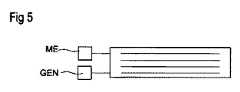
主本体の内部電極の少なくとも2つは、測定ユニットMEに接続され、測定ユニットMEは、主本体の主表面に垂直に加えられる力の結果として作用し、圧電セラミックの逆圧電効果によって発生する電圧を識別することができる。電圧発生器GENは、第1及び第2のアクチュエータ電極E1、E2の2つの外部接点に接続される。測定ユニットMEが、発生した測定電圧の超過に現れるトリガ力に達したことを識別した場合、電圧発生器GENは、アクチュエータ電圧を発生させ、その電圧を第1及び第2のアクチュエータ電極に印加する。アクチュエータ電圧は、触覚フィードバックとしてユーザによって識別される主本体のたわみにつながる。 At least two of the internal electrodes of the main body are connected to the measuring unit ME, which acts as a result of the force applied perpendicularly to the main surface of the main body, the voltage generated by the inverse piezoelectric effect of the piezoelectric ceramic. Can be identified. The voltage generator GEN is connected to two external contacts of the first and second actuator electrodes E1 and E2. When the measuring unit ME identifies that it has reached a trigger force that appears in excess of the measured voltage generated, the voltage generator GEN generates an actuator voltage and applies that voltage to the first and second actuator electrodes. .. The actuator voltage leads to a deflection of the main body identified by the user as haptic feedback.
知覚を増幅するために、アクチュエータ電極に印加される電圧は、様々な連続パルスの形で調節することができる。その場合、その連続周波数は、フィードバックが振動としてユーザによって知覚され得るように選択される。適切な周波数のAC電圧をアクチュエータ電極に印加することも可能である。さらに、測定ユニット及び測定ユニットに接続された制御ユニットで複数の閾値を定義することが可能であり、その場合、これらの閾値は、異なるフィードバックを生成することができる。異なるフィードバックは、周波数、又は一般にパルスの長さ、連続周波数又は数を異なるものとすることができる。それと並行して、デバイスは、その場合には、達した閾値に応じて異なるアクションを起動させることもできる。 To amplify the perception, the voltage applied to the actuator electrodes can be adjusted in the form of various continuous pulses. In that case, the continuous frequency is selected so that the feedback can be perceived by the user as vibration. It is also possible to apply an AC voltage of an appropriate frequency to the actuator electrodes. Further, it is possible to define a plurality of thresholds in the measurement unit and the control unit connected to the measurement unit, in which case these thresholds can generate different feedbacks. Different feedbacks can be of different frequencies, or generally pulse lengths, continuous frequencies or numbers. In parallel, the device can then trigger different actions depending on the threshold reached.
図6Aは、すべてのアクチュエータ電極が測定電極ME1の片側に配置されるように、主本体GKの測定電極ME1の1つの採り得る配置構成を示す。その場合、測定電極ME1は、主本体GKの主表面の近傍に配置され得る。 FIG. 6A shows one possible arrangement configuration of the measurement electrode ME1 of the main body GK so that all actuator electrodes are arranged on one side of the measurement electrode ME1. In that case, the measurement electrode ME1 may be arranged in the vicinity of the main surface of the main body GK.
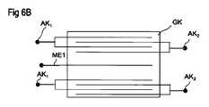
図6Bは、概略断面図に基づいて、測定電極ME1がアクチュエータ電極E1、E2の間にて主本体GKの中心にどのように配置されるかを示す。測定電極ME1とアクチュエータ電極E2との間に形成される距離は、異なる極性のアクチュエータ電極E1、E2の間に形成される距離よりも大きくすることができる。第1のアクチュエータ電極E1は、第1の外部接点Ak1に接続され、第2のアクチュエータ電極E2は、第2の外部接点AK2に接続される。 FIG. 6B shows how the measurement electrode ME1 is arranged at the center of the main body GK between the actuator electrodes E1 and E2 based on a schematic cross-sectional view. The distance formed between the measurement electrode ME1 and the actuator electrode E2 can be larger than the distance formed between the actuator electrodes E1 and E2 having different polarities. The first actuator electrode E1 is connected to the first external contact Ak1, and the second actuator electrode E2 is connected to the second external contact AK2.
図7は、本発明のさらなる実施形態を示し、セラミック製の主本体GK、すなわち圧電材料の主本体は、中央に、好ましくは連続した円筒形の孔Lの形で穿孔されている。切頭円錐形状の金属シートKBの縁部領域は、孔の縁部から十分な距離で主本体の主表面に接着結合される。孔は、アクチュエータ電極間に蓄積する圧電アクチュエータの静電容量を低減するという利点を有し、したがって、低電力且つ変化のない大きな線膨張の場合においてアクチュエータの機能が発揮され得る。 FIG. 7 shows a further embodiment of the present invention, in which the ceramic main body GK, i.e. the main body of the piezoelectric material, is perforated in the center, preferably in the form of continuous cylindrical holes L. The edge region of the truncated cone-shaped metal sheet KB is adhesively bonded to the main surface of the main body at a sufficient distance from the edge of the hole. The holes have the advantage of reducing the capacitance of the piezoelectric actuator that accumulates between the actuator electrodes, thus allowing the actuator to function in the case of low power and large linear expansion without change.
図8は、さらなる実施形態を示し、各場合において、2つの切頭円錐形状の金属シートKBを有する主本体GKを備える複数のデバイスが上下に垂直方向に積み重ねられ、それによりすべての主本体の側縁部が互いに整列している、すなわち基本エリアが100パーセントの範囲で重複している。図示されていないが、この実施形態では、上下に積み重ねられたこれらのデバイスの固定が、作動プレート及びコイルばねを利用してベースBSに対して固定され、スタックが前記ベースに支承されることが特に有利である。ここでも、保持クリップによって主本体を横方向に固定すること、又は適切に閉じる保持クリップ又は他のストッパによってそれらの横滑りを制限することが有利である。この態様でも、主本体が最大限に移動可能であり、線膨張が妨げられず、個々のデバイスの線膨張が相加的に累積し、ベースBの表面の垂直方向上方の法線Nに平行な全体的なたわみを形成することが保証される。 FIG. 8 shows a further embodiment, in which in each case a plurality of devices with a main body GK having two truncated conical metal sheet KBs are stacked vertically vertically in all main bodies thereby. The side edges are aligned with each other, i.e. the basic areas overlap within 100 percent. Although not shown, in this embodiment, the fixation of these vertically stacked devices is secured to the base BS using actuating plates and coil springs, and the stack is supported to the base. It is especially advantageous. Again, it is advantageous to secure the main body laterally with holding clips, or to limit their skidding with holding clips or other stoppers that close properly. Also in this embodiment, the main body is maximally movable, linear expansion is not hindered, linear expansion of individual devices accumulates additively, and is parallel to the normal above the surface of base B in the vertical direction. It is guaranteed to form a good overall deflection.
図9は、主本体GKを備える本発明によるデバイスのさらなる例示的な実施形態を示す。膜MBは、上部のシンバル形要素の上に支持されている。前記膜は、薄く柔軟な形で具現化されている。この支持及び弾性の結果として、膜は、ベースBSに対して作用し、ばね力に相当する力を加える。膜MBは、ユーザにとって視認可能かつ動作可能な表面を構成する。これは、動作表面に隙間がないという利点を有する。 FIG. 9 shows a further exemplary embodiment of a device according to the invention comprising a main body GK. Membrane MB is supported over the upper cymbal-shaped element. The film is embodied in a thin and flexible form. As a result of this support and elasticity, the film acts on the base BS and applies a force corresponding to the spring force. The membrane MB constitutes a surface that is visible and operable to the user. This has the advantage that there are no gaps on the working surface.
膜とベースは、互いに固定的に接続される。これは、例えばねじ接続によって行われ得る(図には示されていない)。膜は、ベースに固定されたフレームRNによっても張力をかけることができる。このようにして、平坦な動作表面が得られる。同時に、薄い膜は、触覚フィードバックが膜によって弱められないことを確実にする。対照的に、ベースは、剛体として構成されている。 The membrane and base are fixedly connected to each other. This can be done, for example, by screw connection (not shown in the figure). The membrane can also be tensioned by a frame RN fixed to the base. In this way, a flat working surface is obtained. At the same time, the thin membrane ensures that tactile feedback is not dampened by the membrane. In contrast, the base is constructed as a rigid body.
図示の構造により、デバイスの作動時に膜のみが変形され、したがってユーザの触覚フィードバックの強度が最大化されることを保証する。加えて、膜MBとベースBSとの間の厚さ又は接続を変えることによって、膜のばね効果を最適化することができる。 The structure shown ensures that only the membrane is deformed when the device is activated, thus maximizing the strength of the user's tactile feedback. In addition, the spring effect of the membrane can be optimized by varying the thickness or connection between the membrane MB and the base BS.
膜は、好適にはアクチュエータの剛性の1%〜50%の範囲の剛性を有するように構成される。 The membrane is preferably configured to have a stiffness in the range of 1% to 50% of the stiffness of the actuator.
動作中にアクチュエータが滑ることを防止するために、前記アクチュエータは、後壁(及び/又は膜)にさらに固着することができる。1つの採り得る固着の方法は、接着剤層KSの手段によるアクチュエータの固定である。 The actuator can be further attached to the rear wall (and / or membrane) to prevent the actuator from slipping during operation. One possible fixing method is to fix the actuator by means of the adhesive layer KS.
特に図4に示されるような長方形又は正方形の基本エリアを有する主本体GKを備える実施形態に加えて、円形の基本エリアを有する主本体を具現化することも可能である。正方形又は長方形の実施形態は、より大きな面積のスタックから主本体が切り出される場合、プロセスエンジニアリングの観点で有効であるだけであり、前記切出しは長方形又は正方形の主本体につながる直線的な切断によって行われる。したがって、主本体は、10〜30mmの辺の長さを有することができ、これは円形の様式で具体化された主本体の寸法にも対応することができる。主本体は、法線の方向に0.5〜2mmの高さを有することができる。 In particular, in addition to the embodiment including the main body GK having a rectangular or square basic area as shown in FIG. 4, it is also possible to embody a main body having a circular basic area. The square or rectangular embodiment is only effective from the viewpoint of process engineering when the main body is cut out from a stack of a larger area, and the cutout is performed by a linear cut leading to the rectangular or square main body. It is said. Therefore, the main body can have a side length of 10 to 30 mm, which can also correspond to the dimensions of the main body embodied in a circular fashion. The main body can have a height of 0.5 to 2 mm in the direction of the normal.
シンバル形要素KBは、力がコンポーネントに加えられず、電圧が第1及び第2のアクチュエータ電極間に存在しない場合、カバー表面DFの中央領域と主本体GKの表面との間の距離が約0.5mmになるように寸法設定することができる。 The cymbal element KB has a distance of about 0 between the central region of the cover surface DF and the surface of the main body GK when no force is applied to the component and no voltage is present between the first and second actuator electrodes. The dimensions can be set to be .5 mm.
デバイスの構造は、好ましくは対称であり、それにより上部及び下部の切頭円錐形状の金属シートは、それらの寸法及び配置に関して互いに対称である。シンバル形要素KBは、主本体の基本エリアに対して最大の水平範囲を有し、それにより最大表面エリアが主本体の主表面に支承される縁部領域内に囲まれる。この場合、2つの金属シートの間に配置されるアクチュエータの容積も最大になる。これにより、横方向収縮を最大限に検出したり、又は最大強度で所望のたわみに横方向収縮を変換したりすることが可能になる。 The structure of the device is preferably symmetrical, whereby the top and bottom truncated cone-shaped metal sheets are symmetrical with respect to their dimensions and arrangement. The cymbal-shaped element KB has a maximum horizontal range with respect to the basic area of the main body, whereby the maximum surface area is surrounded within an edge region supported by the main surface of the main body. In this case, the volume of the actuator arranged between the two metal sheets is also maximized. This makes it possible to detect lateral shrinkage to the maximum or convert lateral shrinkage to the desired deflection at maximum intensity.
本発明は、いくつかの例示的な実施形態に基づいてのみ表すことができたが、例示的な実施形態による厳密な実施形態そのものに限定されない。アクチュエータ電極の数、接続接点の数、又は上下に積み重ねられる主本体の数を必要に応じて変えることは、本発明の範囲内にある。基本エリアの形状を定めることも、まず近似的な面においては、デバイスの有効性には関係しない。触覚フィードバックは、所望の態様で実現することができ、それに応じてたわみを調節することができる。さらに、トリガ力は、実質的に任意に設定することができ、その結果、所望のトリガ力に到達するには、わずかなタッチにより固定圧力に達することだけが必要とされ得る。 The present invention could only be expressed on the basis of some exemplary embodiments, but is not limited to the exact embodiments of the exemplary embodiments. It is within the scope of the present invention to change the number of actuator electrodes, the number of connecting contacts, or the number of main bodies stacked one above the other as necessary. Determining the shape of the basic area also has nothing to do with the effectiveness of the device, first of all in approximate terms. Tactile feedback can be achieved in the desired manner and the deflection can be adjusted accordingly. Moreover, the trigger force can be set substantially arbitrarily, so that it may only be necessary to reach a fixed pressure with a slight touch to reach the desired trigger force.
AA アクチュエータのたわみ
AK 外部接点
B 孔
BS ベース
BP 作動プレート
DF 切頭円錐頂点=カバー表面
E1、E2 第1及び第2のアクチュエータ電極
F アクチュエータに加えられる力
FD、FS 圧縮又は引張プレストレスを有するばね
GEN 電圧発生器
GK 圧電型の主本体
HB 保持クリップ
KB 切頭円錐形状の金属シート/シンバル形要素
KS 接着剤層
L 主本体の孔
ME 測定ユニット
ME1、ME2 第1及び第2の測定電極
MF 金属シートの横方向表面
MN 膜
N 主表面に対する法線
OF1、OF2 主本体の主表面
RB 金属シートの縁部領域
RN フレームAA Actuator deflection AK External contact B Hole BS base BP Actuating plate DF Cleaved cone apex = Cover surface E1, E2 First and second actuator electrodes F Force applied to actuator FD , FS Compression or tensile prestress Spring GEN voltage generator GK piezoelectric type main body HB holding clip KB truncated conical metal sheet / cymbal element KS adhesive layer L main body hole ME measurement unit ME1, ME2 1st and 2nd measurement electrodes Lateral surface of MF metal sheet MN film N Normal to main surface OF1 , OF2 Main surface of main body RB Edge area of metal sheet RN frame
Claims (13)
Translated fromJapanese当該デバイスは、
xy平面において平行平面となっている複数の主表面を有する平坦な圧電型の主本体(GK)と、第1のアクチュエータ電極と、第2のアクチュエータ電極とを有する圧電アクチュエータを備え、
切頭円錐形状の金属シートとして成形されたシンバル形要素(KB)であって、前記シンバル形要素が、前記主表面の1つに固定的に接着結合されるシンバル形要素(KB)を有し、
前記シンバル形要素(KB)の切頭円錐頂点が、前記主本体から離れる方向を向いており、
空洞が、前記シンバル形要素(KB)と前記主本体(GK)との間に囲まれており、
孔(B)が前記シンバル形要素に設けられ、前記孔が、前記空洞とその周囲との間の圧力均等化を可能にする、デバイス。A device for generating active tactile feedback
The device is
A piezoelectric actuator having a flat piezoelectric main body (GK) having a plurality of main surfaces parallel to the xy plane, a first actuator electrode, and a second actuator electrode is provided.
A cymbal-shaped element (KB) formed as a metal sheet having a truncated conical shape, wherein the cymbal-shaped element has a cymbal-shaped element (KB) that is fixedly adherently bonded to one of the main surfaces. ,
The truncated conical apex of the cymbal element (KB) points away from the main body.
The cavity is surrounded by the cymbal element (KB) and the main body (GK).
A device in which a hole (B) is provided in the cymbal element, and the hole allows pressure equalization between the cavity and its surroundings.
請求項1〜3のいずれか一項に記載のデバイス。The cymbal-shaped element (KB) causes the deflection of the main body (GK) in the xy plane of the main surface to force the deformation of the cymbal-shaped element, resulting in the deflection in the z direction, and thus the said main body. Configured to configure active tactile feedback for deflection,
The device according to any one of claims 1 to 3.
前記シンバル形要素が、前記切頭円錐頂点にカバー表面(DF)を備え、前記カバー表面が、前記主本体(GK)の前記主表面に平行に配向され、又は解剖学的に適合された指のくぼみを備える、請求項1〜4のいずれか一項に記載のデバイス。The cymbal element (KB) comprises a lateral surface (MF) projecting above the main surface corresponding to the direction of the normal (N).
The cymbal-shaped element comprises a cover surface (DF) at the apex of the truncated cone, the cover surface being oriented parallel to or anatomically fitted to the main surface of the main body (GK). The device according to any one of claims 1 to 4, comprising a recess.
測定ユニット(ME)が、前記測定電極と前記第1及び第2のアクチュエータ電極の一方との間にて発生される測定電圧であって、前記主本体(GK)に加えられる力によって生ずる測定電圧を測定するために設けられ、
当該デバイスが、前記測定ユニット(ME)によって検出された前記測定電圧がトリガ力に割り当てられた閾値を超えた時にこの加えられた力を識別するように構成されており、
電圧発生器によって、前記トリガ力が達した時に、アクチュエータ電圧が発生されて前記第1及び第2のアクチュエータ電極に印加され、この場合、同時に当該デバイス又は当該デバイスに接続された電気コンポーネントが動作するように機能するさらなるアクションが起動される、請求項1〜7のいずれか一項に記載のデバイス。The measurement electrode (ME1) is arranged on the main body (GK).
The measurement voltage generated by the measurement unit (ME) between the measurement electrode and one of the first and second actuator electrodes, and the measurement voltage generated by the force applied to the main body (GK). Provided to measure
The device is configured to identify the applied force when the measured voltage detected by the measuring unit (ME) exceeds a threshold assigned to the trigger force.
When the trigger force is reached by the voltage generator, an actuator voltage is generated and applied to the first and second actuator electrodes, in which case the device or an electrical component connected to the device operates at the same time. The device according to any one of claims 1 to 7, wherein further actions that function as such are invoked.
測定ユニットが、前記第1及び第2のアクチュエータ電極間の測定電圧を決定するように構成されている、請求項1〜8のいずれか一項に記載のデバイス。The first and second actuator electrodes also form a measurement electrode at the same time.
The device according to any one of claims 1 to 8, wherein the measuring unit is configured to determine a measured voltage between the first and second actuator electrodes.
Applications Claiming Priority (3)
| Application Number | Priority Date | Filing Date | Title |
|---|---|---|---|
| ATGM50142/2017 | 2017-07-26 | ||
| ATGM50142/2017UAT15914U1 (en) | 2017-07-26 | 2017-07-26 | Device that provides haptic feedback and device with the device |
| PCT/EP2017/079883WO2019020205A1 (en) | 2017-07-26 | 2017-11-21 | DEVICE THAT GIVES A HAPTIC FEEDBACK AND CONSTRUCTION ELEMENT WITH THE DEVICE |
Publications (1)
| Publication Number | Publication Date |
|---|---|
| JP2020528001Atrue JP2020528001A (en) | 2020-09-17 |
Family
ID=63529145
Family Applications (1)
| Application Number | Title | Priority Date | Filing Date |
|---|---|---|---|
| JP2019570535APendingJP2020528001A (en) | 2017-07-26 | 2017-11-21 | A device that conveys haptic feedback, and the components that provide that device. |
Country Status (6)
| Country | Link |
|---|---|
| US (1) | US11640205B2 (en) |
| EP (1) | EP3619593B1 (en) |
| JP (1) | JP2020528001A (en) |
| CN (1) | CN110914785B (en) |
| AT (1) | AT15914U1 (en) |
| WO (1) | WO2019020205A1 (en) |
Families Citing this family (34)
| Publication number | Priority date | Publication date | Assignee | Title |
|---|---|---|---|---|
| US10732714B2 (en) | 2017-05-08 | 2020-08-04 | Cirrus Logic, Inc. | Integrated haptic system |
| US11259121B2 (en) | 2017-07-21 | 2022-02-22 | Cirrus Logic, Inc. | Surface speaker |
| US10832537B2 (en) | 2018-04-04 | 2020-11-10 | Cirrus Logic, Inc. | Methods and apparatus for outputting a haptic signal to a haptic transducer |
| US11269415B2 (en) | 2018-08-14 | 2022-03-08 | Cirrus Logic, Inc. | Haptic output systems |
| GB201817495D0 (en) | 2018-10-26 | 2018-12-12 | Cirrus Logic Int Semiconductor Ltd | A force sensing system and method |
| US11644370B2 (en)* | 2019-03-29 | 2023-05-09 | Cirrus Logic, Inc. | Force sensing with an electromagnetic load |
| US12035445B2 (en) | 2019-03-29 | 2024-07-09 | Cirrus Logic Inc. | Resonant tracking of an electromagnetic load |
| US10992297B2 (en) | 2019-03-29 | 2021-04-27 | Cirrus Logic, Inc. | Device comprising force sensors |
| US10828672B2 (en) | 2019-03-29 | 2020-11-10 | Cirrus Logic, Inc. | Driver circuitry |
| US10726683B1 (en) | 2019-03-29 | 2020-07-28 | Cirrus Logic, Inc. | Identifying mechanical impedance of an electromagnetic load using a two-tone stimulus |
| US10955955B2 (en) | 2019-03-29 | 2021-03-23 | Cirrus Logic, Inc. | Controller for use in a device comprising force sensors |
| US11509292B2 (en) | 2019-03-29 | 2022-11-22 | Cirrus Logic, Inc. | Identifying mechanical impedance of an electromagnetic load using least-mean-squares filter |
| US12176781B2 (en) | 2019-03-29 | 2024-12-24 | Cirrus Logic Inc. | Methods and systems for estimating transducer parameters |
| US10976825B2 (en) | 2019-06-07 | 2021-04-13 | Cirrus Logic, Inc. | Methods and apparatuses for controlling operation of a vibrational output system and/or operation of an input sensor system |
| WO2020254788A1 (en) | 2019-06-21 | 2020-12-24 | Cirrus Logic International Semiconductor Limited | A method and apparatus for configuring a plurality of virtual buttons on a device |
| US11632063B1 (en)* | 2019-08-27 | 2023-04-18 | Meta Platforms Technologies, Llc | Structured actuators |
| US11408787B2 (en) | 2019-10-15 | 2022-08-09 | Cirrus Logic, Inc. | Control methods for a force sensor system |
| US11380175B2 (en) | 2019-10-24 | 2022-07-05 | Cirrus Logic, Inc. | Reproducibility of haptic waveform |
| WO2021078561A1 (en)* | 2019-10-25 | 2021-04-29 | Tdk Electronics Ag | Electroceramic multilayer component |
| US12276687B2 (en) | 2019-12-05 | 2025-04-15 | Cirrus Logic Inc. | Methods and systems for estimating coil impedance of an electromagnetic transducer |
| US11545951B2 (en) | 2019-12-06 | 2023-01-03 | Cirrus Logic, Inc. | Methods and systems for detecting and managing amplifier instability |
| US12244253B2 (en) | 2020-04-16 | 2025-03-04 | Cirrus Logic Inc. | Restricting undesired movement of a haptic actuator |
| US11662821B2 (en) | 2020-04-16 | 2023-05-30 | Cirrus Logic, Inc. | In-situ monitoring, calibration, and testing of a haptic actuator |
| JP7347662B2 (en)* | 2020-04-30 | 2023-09-20 | 株式会社村田製作所 | Vibration structure, vibration device and tactile presentation device |
| CN114375505A (en) | 2020-07-14 | 2022-04-19 | Tdk电子股份有限公司 | Device for generating haptic signals |
| CN114079401A (en)* | 2020-08-17 | 2022-02-22 | 华为技术有限公司 | Drive assembly, motor and terminal |
| DE102020123436A1 (en)* | 2020-09-08 | 2022-03-10 | Next System Vertriebsges.M.B.H. | actuator unit |
| DE102021113843A1 (en) | 2021-05-28 | 2022-12-01 | Tdk Electronics Ag | contraption |
| CN113224971B (en)* | 2021-06-04 | 2024-08-02 | 苏州丰泰医疗科技有限公司 | Pen-type piezoelectric ceramic stack displacement device |
| US11933822B2 (en) | 2021-06-16 | 2024-03-19 | Cirrus Logic Inc. | Methods and systems for in-system estimation of actuator parameters |
| US11765499B2 (en) | 2021-06-22 | 2023-09-19 | Cirrus Logic Inc. | Methods and systems for managing mixed mode electromechanical actuator drive |
| US11908310B2 (en) | 2021-06-22 | 2024-02-20 | Cirrus Logic Inc. | Methods and systems for detecting and managing unexpected spectral content in an amplifier system |
| US11552649B1 (en) | 2021-12-03 | 2023-01-10 | Cirrus Logic, Inc. | Analog-to-digital converter-embedded fixed-phase variable gain amplifier stages for dual monitoring paths |
| CN114674411A (en)* | 2022-03-02 | 2022-06-28 | 浙江大学 | Fiber grating hydrophone adopting double cymbals-shaped diaphragms |
Citations (19)
| Publication number | Priority date | Publication date | Assignee | Title |
|---|---|---|---|---|
| US2386279A (en)* | 1942-07-21 | 1945-10-09 | Raymond W Tibbetts | Piezoelectric device |
| US2895062A (en)* | 1955-12-22 | 1959-07-14 | Frank R Abbott | Broad band electroacoustic transducer |
| JPH02246248A (en)* | 1989-03-20 | 1990-10-02 | Mitsubishi Electric Corp | Integrated circuit package manufacturing method and device |
| JPH06338640A (en)* | 1993-05-27 | 1994-12-06 | Omron Corp | Piezoelectric actuator, and manipulator, optical scanning device, photosensor, flow rate controller, stage device, focal point adjustimg mechanism and optical device using the actuator |
| JPH07162051A (en)* | 1993-12-07 | 1995-06-23 | Omron Corp | Piezoelectric actuator, focal point adjusting mechanism using the same, optical equipment and focal point position variable light source |
| US5729077A (en)* | 1995-12-15 | 1998-03-17 | The Penn State Research Foundation | Metal-electroactive ceramic composite transducer |
| US6798888B1 (en)* | 2002-11-05 | 2004-09-28 | The United States Of America As Represented By The Secretary Of The Navy | Mount for underwater acoustic projector |
| US20050057123A1 (en)* | 2003-07-11 | 2005-03-17 | Deng Ken Kan | Piezoelectric vibration energy harvesting device and method |
| JP2006048302A (en)* | 2004-08-03 | 2006-02-16 | Sony Corp | Piezoelectric composite device, manufacturing method thereof, handling method thereof, control method thereof, input / output device and electronic apparatus |
| JP2006129625A (en)* | 2004-10-29 | 2006-05-18 | Konica Minolta Opto Inc | Drive unit |
| US20090303839A1 (en)* | 2007-07-31 | 2009-12-10 | Manoj Narayanan | Stress-biased cymbals incorporating a shape memory alloy |
| US20110127881A1 (en)* | 2008-09-19 | 2011-06-02 | Howarth Thomas R | Piezoelectric generator and method |
| JP2012203195A (en)* | 2011-03-25 | 2012-10-22 | Fujifilm Corp | Method for manufacturing lens module and imaging apparatus |
| CN204167367U (en)* | 2014-11-13 | 2015-02-18 | 中路高科交通科技集团有限公司 | A kind of cymbals formula piezo-electric device |
| US20150187349A1 (en)* | 2013-12-30 | 2015-07-02 | Photosonix Medical, Inc. | Flextensional transducers and related methods |
| JP2015527724A (en)* | 2012-05-08 | 2015-09-17 | アイト ベスローテンヴェンノーツハップ | Piezoelectric device and apparatus |
| US20160023245A1 (en)* | 2013-03-11 | 2016-01-28 | Apple Inc. | Portable electronic device using a tactile vibrator |
| JP2017004240A (en)* | 2015-06-10 | 2017-01-05 | 日本電信電話株式会社 | Direction presentation device |
| CA2996919A1 (en)* | 2015-10-09 | 2017-04-13 | Epcos Ag | Component for producing active haptic feedback |
Family Cites Families (21)
| Publication number | Priority date | Publication date | Assignee | Title |
|---|---|---|---|---|
| US5276657A (en)* | 1992-02-12 | 1994-01-04 | The Pennsylvania Research Corporation | Metal-electroactive ceramic composite actuators |
| JP3565560B2 (en) | 1994-05-20 | 2004-09-15 | 新世株式会社 | Sound generator |
| US6465936B1 (en)* | 1998-02-19 | 2002-10-15 | Qortek, Inc. | Flextensional transducer assembly and method for its manufacture |
| GB2349738B (en)* | 1999-05-07 | 2003-08-06 | Univ Cranfield | Improvements in or relating to ultrasonic motors |
| US6798122B1 (en) | 2002-11-05 | 2004-09-28 | The United States Of America As Represented By The Secretary Of The Navy | Lightweight underwater acoustic projector |
| US8350345B2 (en)* | 2003-12-29 | 2013-01-08 | Vladimir Vaganov | Three-dimensional input control device |
| DE102004055996A1 (en)* | 2004-11-19 | 2006-05-24 | Stefan Eickenberg | Piezoelectric flexural actuator e.g. as sensor, includes carrier with one face fully or partly hardened |
| US8221366B2 (en)* | 2007-09-05 | 2012-07-17 | Integra Lifesciences Corporation | Volume limiting bodily fluid drainage system |
| JP2009077502A (en)* | 2007-09-20 | 2009-04-09 | Alps Electric Co Ltd | Tactile sense reaction force device for touch switch |
| WO2009099805A2 (en)* | 2008-02-01 | 2009-08-13 | Piezo Resonance Innovations, Inc. | Phaco-emulsification handpiece |
| DE112009002215T5 (en)* | 2008-09-15 | 2011-07-28 | Piezo Resonance Innovations, Inc., Pa. | Medical instrument for reducing the penetration force with means for feedback |
| CN102272702A (en)* | 2008-11-04 | 2011-12-07 | 拜尔材料科学股份公司 | Electroactive polymer transducers for tactile feedback devices |
| EP2315101B1 (en)* | 2009-10-02 | 2014-01-29 | BlackBerry Limited | A method of waking up and a portable electronic device configured to perform the same |
| EP2528125B1 (en)* | 2010-09-24 | 2014-11-26 | BlackBerry Limited | Piezoelectric actuator assembly |
| CN103994059B (en)* | 2014-06-05 | 2015-04-08 | 吉林大学 | Resonance piezoelectric fan with cymbal-shaped cavity |
| DE102014010095A1 (en)* | 2014-07-07 | 2016-01-07 | Jörg Schmeck | Electronic plastic cymbal with the look and feel of an acoustic cymbal. |
| CN104283460B (en)* | 2014-10-11 | 2017-04-05 | 北京工业大学 | Multi-direction vibrational energy harvester |
| CN104377300A (en)* | 2014-10-28 | 2015-02-25 | 安费诺(常州)电子有限公司 | Piezoelectric transducer |
| JP6417247B2 (en)* | 2015-03-17 | 2018-10-31 | アルプス電気株式会社 | Press operation device |
| US20170153703A1 (en)* | 2015-11-30 | 2017-06-01 | Microsoft Technology Licensing, Llc | Piezoelectric haptic feedback structure |
| US10345910B1 (en)* | 2018-06-15 | 2019-07-09 | Immersion Corporation | Haptic actuator assembly with a spring pre-load device |
- 2017
- 2017-07-26ATATGM50142/2017Upatent/AT15914U1/enunknown
- 2017-11-21EPEP17816471.1Apatent/EP3619593B1/enactiveActive
- 2017-11-21WOPCT/EP2017/079883patent/WO2019020205A1/ennot_activeCeased
- 2017-11-21USUS16/630,306patent/US11640205B2/enactiveActive
- 2017-11-21JPJP2019570535Apatent/JP2020528001A/enactivePending
- 2017-11-21CNCN201780093373.XApatent/CN110914785B/enactiveActive
Patent Citations (20)
| Publication number | Priority date | Publication date | Assignee | Title |
|---|---|---|---|---|
| US2386279A (en)* | 1942-07-21 | 1945-10-09 | Raymond W Tibbetts | Piezoelectric device |
| US2895062A (en)* | 1955-12-22 | 1959-07-14 | Frank R Abbott | Broad band electroacoustic transducer |
| JPH02246248A (en)* | 1989-03-20 | 1990-10-02 | Mitsubishi Electric Corp | Integrated circuit package manufacturing method and device |
| JPH06338640A (en)* | 1993-05-27 | 1994-12-06 | Omron Corp | Piezoelectric actuator, and manipulator, optical scanning device, photosensor, flow rate controller, stage device, focal point adjustimg mechanism and optical device using the actuator |
| JPH07162051A (en)* | 1993-12-07 | 1995-06-23 | Omron Corp | Piezoelectric actuator, focal point adjusting mechanism using the same, optical equipment and focal point position variable light source |
| US5729077A (en)* | 1995-12-15 | 1998-03-17 | The Penn State Research Foundation | Metal-electroactive ceramic composite transducer |
| JP2000502210A (en)* | 1995-12-15 | 2000-02-22 | ザ・ペン・ステイト・リサーチ・ファウンデイション | Metal-electroactive ceramic composite converter |
| US6798888B1 (en)* | 2002-11-05 | 2004-09-28 | The United States Of America As Represented By The Secretary Of The Navy | Mount for underwater acoustic projector |
| US20050057123A1 (en)* | 2003-07-11 | 2005-03-17 | Deng Ken Kan | Piezoelectric vibration energy harvesting device and method |
| JP2006048302A (en)* | 2004-08-03 | 2006-02-16 | Sony Corp | Piezoelectric composite device, manufacturing method thereof, handling method thereof, control method thereof, input / output device and electronic apparatus |
| JP2006129625A (en)* | 2004-10-29 | 2006-05-18 | Konica Minolta Opto Inc | Drive unit |
| US20090303839A1 (en)* | 2007-07-31 | 2009-12-10 | Manoj Narayanan | Stress-biased cymbals incorporating a shape memory alloy |
| US20110127881A1 (en)* | 2008-09-19 | 2011-06-02 | Howarth Thomas R | Piezoelectric generator and method |
| JP2012203195A (en)* | 2011-03-25 | 2012-10-22 | Fujifilm Corp | Method for manufacturing lens module and imaging apparatus |
| JP2015527724A (en)* | 2012-05-08 | 2015-09-17 | アイト ベスローテンヴェンノーツハップ | Piezoelectric device and apparatus |
| US20160023245A1 (en)* | 2013-03-11 | 2016-01-28 | Apple Inc. | Portable electronic device using a tactile vibrator |
| US20150187349A1 (en)* | 2013-12-30 | 2015-07-02 | Photosonix Medical, Inc. | Flextensional transducers and related methods |
| CN204167367U (en)* | 2014-11-13 | 2015-02-18 | 中路高科交通科技集团有限公司 | A kind of cymbals formula piezo-electric device |
| JP2017004240A (en)* | 2015-06-10 | 2017-01-05 | 日本電信電話株式会社 | Direction presentation device |
| CA2996919A1 (en)* | 2015-10-09 | 2017-04-13 | Epcos Ag | Component for producing active haptic feedback |
Also Published As
| Publication number | Publication date |
|---|---|
| EP3619593A1 (en) | 2020-03-11 |
| CN110914785B (en) | 2024-06-28 |
| US11640205B2 (en) | 2023-05-02 |
| EP3619593B1 (en) | 2022-10-05 |
| CN110914785A (en) | 2020-03-24 |
| AT15914U1 (en) | 2018-09-15 |
| US20210365118A1 (en) | 2021-11-25 |
| WO2019020205A1 (en) | 2019-01-31 |
Similar Documents
| Publication | Publication Date | Title |
|---|---|---|
| JP2020528001A (en) | A device that conveys haptic feedback, and the components that provide that device. | |
| JP7063898B2 (en) | A device that transmits haptic feedback and a device equipped with the device. | |
| JP7125494B2 (en) | Apparatus and method for generating active haptic feedback | |
| CN108140721B (en) | Devices for generating active haptic feedback | |
| JP5558577B2 (en) | Piezoelectric vibration device and portable terminal using the same | |
| JP5409925B2 (en) | Piezoelectric vibration device and portable terminal using the same | |
| JP7394066B2 (en) | Device for generating haptic feedback | |
| JP2019530111A (en) | Device for generating tactile feedback | |
| CN108269911A (en) | Inertial haptic actuator with cantilever beam and intellectual material | |
| KR101576444B1 (en) | Button device using piezoelectric element | |
| US20230001451A1 (en) | Vibration structure, vibration device, and tactile sense presentation device | |
| US10644219B2 (en) | Piezoelectric vibration module | |
| KR101010738B1 (en) | Piezoelectric speaker | |
| CN114375505A (en) | Device for generating haptic signals | |
| JPWO2017104530A1 (en) | Piezoelectric generator | |
| JP2017063279A (en) | Sound generator | |
| JP2021028799A (en) | Vibration unit | |
| KR101544124B1 (en) | Piezoelectric vibrating device | |
| JP6382707B2 (en) | Sound generator and speaker equipped with the same | |
| JP6346075B2 (en) | Sound generator | |
| KR101568773B1 (en) | piezo-electric vibrator |
Legal Events
| Date | Code | Title | Description |
|---|---|---|---|
| A621 | Written request for application examination | Free format text:JAPANESE INTERMEDIATE CODE: A621 Effective date:20200219 | |
| A131 | Notification of reasons for refusal | Free format text:JAPANESE INTERMEDIATE CODE: A131 Effective date:20210105 | |
| A977 | Report on retrieval | Free format text:JAPANESE INTERMEDIATE CODE: A971007 Effective date:20201228 | |
| A521 | Request for written amendment filed | Free format text:JAPANESE INTERMEDIATE CODE: A523 Effective date:20210319 | |
| A02 | Decision of refusal | Free format text:JAPANESE INTERMEDIATE CODE: A02 Effective date:20210413 |