JP2020525165A - Battery pack and associated surgical instrument having integrated circuit for providing sleep mode to the battery pack - Google Patents
Battery pack and associated surgical instrument having integrated circuit for providing sleep mode to the battery packDownload PDFInfo
- Publication number
- JP2020525165A JP2020525165AJP2019571727AJP2019571727AJP2020525165AJP 2020525165 AJP2020525165 AJP 2020525165AJP 2019571727 AJP2019571727 AJP 2019571727AJP 2019571727 AJP2019571727 AJP 2019571727AJP 2020525165 AJP2020525165 AJP 2020525165A
- Authority
- JP
- Japan
- Prior art keywords
- control circuit
- assembly
- state
- handle assembly
- battery pack
- Prior art date
- Legal status (The legal status is an assumption and is not a legal conclusion. Google has not performed a legal analysis and makes no representation as to the accuracy of the status listed.)
- Granted
Links
Images


Classifications
- A—HUMAN NECESSITIES
- A61—MEDICAL OR VETERINARY SCIENCE; HYGIENE
- A61B—DIAGNOSIS; SURGERY; IDENTIFICATION
- A61B17/00—Surgical instruments, devices or methods
- A61B17/068—Surgical staplers, e.g. containing multiple staples or clamps
- A61B17/072—Surgical staplers, e.g. containing multiple staples or clamps for applying a row of staples in a single action, e.g. the staples being applied simultaneously
- A61B17/07207—Surgical staplers, e.g. containing multiple staples or clamps for applying a row of staples in a single action, e.g. the staples being applied simultaneously the staples being applied sequentially
- A—HUMAN NECESSITIES
- A61—MEDICAL OR VETERINARY SCIENCE; HYGIENE
- A61B—DIAGNOSIS; SURGERY; IDENTIFICATION
- A61B17/00—Surgical instruments, devices or methods
- A61B17/00234—Surgical instruments, devices or methods for minimally invasive surgery
- A—HUMAN NECESSITIES
- A61—MEDICAL OR VETERINARY SCIENCE; HYGIENE
- A61B—DIAGNOSIS; SURGERY; IDENTIFICATION
- A61B17/00—Surgical instruments, devices or methods
- A61B17/068—Surgical staplers, e.g. containing multiple staples or clamps
- A61B17/072—Surgical staplers, e.g. containing multiple staples or clamps for applying a row of staples in a single action, e.g. the staples being applied simultaneously
- A—HUMAN NECESSITIES
- A61—MEDICAL OR VETERINARY SCIENCE; HYGIENE
- A61B—DIAGNOSIS; SURGERY; IDENTIFICATION
- A61B17/00—Surgical instruments, devices or methods
- A61B17/11—Surgical instruments, devices or methods for performing anastomosis; Buttons for anastomosis
- A61B17/115—Staplers for performing anastomosis, e.g. in a single operation
- A61B17/1155—Circular staplers comprising a plurality of staples
- A—HUMAN NECESSITIES
- A61—MEDICAL OR VETERINARY SCIENCE; HYGIENE
- A61B—DIAGNOSIS; SURGERY; IDENTIFICATION
- A61B90/00—Instruments, implements or accessories specially adapted for surgery or diagnosis and not covered by any of the groups A61B1/00 - A61B50/00, e.g. for luxation treatment or for protecting wound edges
- A61B90/70—Cleaning devices specially adapted for surgical instruments
- A—HUMAN NECESSITIES
- A61—MEDICAL OR VETERINARY SCIENCE; HYGIENE
- A61B—DIAGNOSIS; SURGERY; IDENTIFICATION
- A61B90/00—Instruments, implements or accessories specially adapted for surgery or diagnosis and not covered by any of the groups A61B1/00 - A61B50/00, e.g. for luxation treatment or for protecting wound edges
- A61B90/90—Identification means for patients or instruments, e.g. tags
- A61B90/98—Identification means for patients or instruments, e.g. tags using electromagnetic means, e.g. transponders
- H—ELECTRICITY
- H01—ELECTRIC ELEMENTS
- H01M—PROCESSES OR MEANS, e.g. BATTERIES, FOR THE DIRECT CONVERSION OF CHEMICAL ENERGY INTO ELECTRICAL ENERGY
- H01M10/00—Secondary cells; Manufacture thereof
- H01M10/42—Methods or arrangements for servicing or maintenance of secondary cells or secondary half-cells
- H01M10/425—Structural combination with electronic components, e.g. electronic circuits integrated to the outside of the casing
- H—ELECTRICITY
- H01—ELECTRIC ELEMENTS
- H01M—PROCESSES OR MEANS, e.g. BATTERIES, FOR THE DIRECT CONVERSION OF CHEMICAL ENERGY INTO ELECTRICAL ENERGY
- H01M50/00—Constructional details or processes of manufacture of the non-active parts of electrochemical cells other than fuel cells, e.g. hybrid cells
- H01M50/20—Mountings; Secondary casings or frames; Racks, modules or packs; Suspension devices; Shock absorbers; Transport or carrying devices; Holders
- A—HUMAN NECESSITIES
- A61—MEDICAL OR VETERINARY SCIENCE; HYGIENE
- A61B—DIAGNOSIS; SURGERY; IDENTIFICATION
- A61B17/00—Surgical instruments, devices or methods
- A61B2017/00017—Electrical control of surgical instruments
- A—HUMAN NECESSITIES
- A61—MEDICAL OR VETERINARY SCIENCE; HYGIENE
- A61B—DIAGNOSIS; SURGERY; IDENTIFICATION
- A61B17/00—Surgical instruments, devices or methods
- A61B2017/00017—Electrical control of surgical instruments
- A61B2017/00022—Sensing or detecting at the treatment site
- A61B2017/00084—Temperature
- A—HUMAN NECESSITIES
- A61—MEDICAL OR VETERINARY SCIENCE; HYGIENE
- A61B—DIAGNOSIS; SURGERY; IDENTIFICATION
- A61B17/00—Surgical instruments, devices or methods
- A61B2017/00367—Details of actuation of instruments, e.g. relations between pushing buttons, or the like, and activation of the tool, working tip, or the like
- A61B2017/00398—Details of actuation of instruments, e.g. relations between pushing buttons, or the like, and activation of the tool, working tip, or the like using powered actuators, e.g. stepper motors, solenoids
- A—HUMAN NECESSITIES
- A61—MEDICAL OR VETERINARY SCIENCE; HYGIENE
- A61B—DIAGNOSIS; SURGERY; IDENTIFICATION
- A61B17/00—Surgical instruments, devices or methods
- A61B2017/0046—Surgical instruments, devices or methods with a releasable handle; with handle and operating part separable
- A—HUMAN NECESSITIES
- A61—MEDICAL OR VETERINARY SCIENCE; HYGIENE
- A61B—DIAGNOSIS; SURGERY; IDENTIFICATION
- A61B17/00—Surgical instruments, devices or methods
- A61B2017/0046—Surgical instruments, devices or methods with a releasable handle; with handle and operating part separable
- A61B2017/00464—Surgical instruments, devices or methods with a releasable handle; with handle and operating part separable for use with different instruments
- A—HUMAN NECESSITIES
- A61—MEDICAL OR VETERINARY SCIENCE; HYGIENE
- A61B—DIAGNOSIS; SURGERY; IDENTIFICATION
- A61B17/00—Surgical instruments, devices or methods
- A61B2017/00681—Aspects not otherwise provided for
- A61B2017/00734—Aspects not otherwise provided for battery operated
- A—HUMAN NECESSITIES
- A61—MEDICAL OR VETERINARY SCIENCE; HYGIENE
- A61B—DIAGNOSIS; SURGERY; IDENTIFICATION
- A61B17/00—Surgical instruments, devices or methods
- A61B17/28—Surgical forceps
- A61B17/29—Forceps for use in minimally invasive surgery
- A61B2017/2926—Details of heads or jaws
- A61B2017/2927—Details of heads or jaws the angular position of the head being adjustable with respect to the shaft
- A—HUMAN NECESSITIES
- A61—MEDICAL OR VETERINARY SCIENCE; HYGIENE
- A61B—DIAGNOSIS; SURGERY; IDENTIFICATION
- A61B90/00—Instruments, implements or accessories specially adapted for surgery or diagnosis and not covered by any of the groups A61B1/00 - A61B50/00, e.g. for luxation treatment or for protecting wound edges
- A61B90/08—Accessories or related features not otherwise provided for
- A61B2090/0803—Counting the number of times an instrument is used
- A—HUMAN NECESSITIES
- A61—MEDICAL OR VETERINARY SCIENCE; HYGIENE
- A61B—DIAGNOSIS; SURGERY; IDENTIFICATION
- A61B90/00—Instruments, implements or accessories specially adapted for surgery or diagnosis and not covered by any of the groups A61B1/00 - A61B50/00, e.g. for luxation treatment or for protecting wound edges
- A61B90/08—Accessories or related features not otherwise provided for
- A61B2090/0813—Accessories designed for easy sterilising, i.e. re-usable
- H—ELECTRICITY
- H01—ELECTRIC ELEMENTS
- H01M—PROCESSES OR MEANS, e.g. BATTERIES, FOR THE DIRECT CONVERSION OF CHEMICAL ENERGY INTO ELECTRICAL ENERGY
- H01M10/00—Secondary cells; Manufacture thereof
- H01M10/42—Methods or arrangements for servicing or maintenance of secondary cells or secondary half-cells
- H01M10/48—Accumulators combined with arrangements for measuring, testing or indicating the condition of cells, e.g. the level or density of the electrolyte
- H—ELECTRICITY
- H01—ELECTRIC ELEMENTS
- H01M—PROCESSES OR MEANS, e.g. BATTERIES, FOR THE DIRECT CONVERSION OF CHEMICAL ENERGY INTO ELECTRICAL ENERGY
- H01M2220/00—Batteries for particular applications
- H01M2220/30—Batteries in portable systems, e.g. mobile phone, laptop
- H—ELECTRICITY
- H01—ELECTRIC ELEMENTS
- H01R—ELECTRICALLY-CONDUCTIVE CONNECTIONS; STRUCTURAL ASSOCIATIONS OF A PLURALITY OF MUTUALLY-INSULATED ELECTRICAL CONNECTING ELEMENTS; COUPLING DEVICES; CURRENT COLLECTORS
- H01R31/00—Coupling parts supported only by co-operation with counterpart
- Y—GENERAL TAGGING OF NEW TECHNOLOGICAL DEVELOPMENTS; GENERAL TAGGING OF CROSS-SECTIONAL TECHNOLOGIES SPANNING OVER SEVERAL SECTIONS OF THE IPC; TECHNICAL SUBJECTS COVERED BY FORMER USPC CROSS-REFERENCE ART COLLECTIONS [XRACs] AND DIGESTS
- Y02—TECHNOLOGIES OR APPLICATIONS FOR MITIGATION OR ADAPTATION AGAINST CLIMATE CHANGE
- Y02E—REDUCTION OF GREENHOUSE GAS [GHG] EMISSIONS, RELATED TO ENERGY GENERATION, TRANSMISSION OR DISTRIBUTION
- Y02E60/00—Enabling technologies; Technologies with a potential or indirect contribution to GHG emissions mitigation
- Y02E60/10—Energy storage using batteries
Landscapes
- Health & Medical Sciences (AREA)
- Surgery (AREA)
- Life Sciences & Earth Sciences (AREA)
- Engineering & Computer Science (AREA)
- Veterinary Medicine (AREA)
- Biomedical Technology (AREA)
- Heart & Thoracic Surgery (AREA)
- Medical Informatics (AREA)
- Molecular Biology (AREA)
- Animal Behavior & Ethology (AREA)
- General Health & Medical Sciences (AREA)
- Public Health (AREA)
- Nuclear Medicine, Radiotherapy & Molecular Imaging (AREA)
- Pathology (AREA)
- Oral & Maxillofacial Surgery (AREA)
- Chemical & Material Sciences (AREA)
- Chemical Kinetics & Catalysis (AREA)
- Electrochemistry (AREA)
- General Chemical & Material Sciences (AREA)
- Manufacturing & Machinery (AREA)
- Microelectronics & Electronic Packaging (AREA)
- Physics & Mathematics (AREA)
- Electromagnetism (AREA)
- Surgical Instruments (AREA)
- Power Engineering (AREA)
Abstract
Translated fromJapaneseDescription
Translated fromJapanese切開創をより小さくすることで、術後の回復時間及び合併症を低減させ得ることから、一部の状況では、従来の開腹外科用デバイスよりも内視鏡外科用器具が好ましい場合がある。このため、内視鏡外科用器具の中には、トロカールのカニューレを通して所望の手術部位に遠位エンドエフェクタを配置するのに適したものがある。これらの遠位エンドエフェクタは、様々な形で組織と係合して診断又は治療効果を得ることができる(例えば、エンドカッター、把持具、カッター、ステープラ、クリップアプライヤ、アクセスデバイス、薬物/遺伝子治療送達デバイス、及び、超音波振動、RF、レーザなどを使用するエネルギー送達デバイスなど)。内視鏡外科用器具は、エンドエフェクタとハンドル部分との間に、臨床医によって操作されるシャフトを含み得る。このようなシャフトは、所望の深さへの挿入及びシャフトの長手方向軸を中心とした回転を可能にし、それにより患者の体内でエンドエフェクタの位置付けを行うことを容易にする。エンドエフェクタの位置付けは、エンドエフェクタをシャフトの長手方向軸に対して選択的に関節動作させるか又は別様に偏向させることを可能にする、1つ以上の関節ジョイント又は機構を含めることによって更に容易にすることができる。 In some situations, endoscopic surgical instruments may be preferable to conventional open surgical devices because smaller incisions may reduce post-operative recovery time and complications. As such, some endoscopic surgical instruments are suitable for placement of a distal end effector through a trocar cannula at a desired surgical site. These distal end effectors can engage tissue in a variety of ways to achieve diagnostic or therapeutic effects (eg, end cutters, graspers, cutters, staplers, clip appliers, access devices, drugs/genes). Therapeutic delivery devices and energy delivery devices using ultrasonic vibration, RF, lasers, etc.). The endoscopic surgical instrument may include a shaft manipulated by a clinician between the end effector and the handle portion. Such a shaft allows insertion to a desired depth and rotation about the longitudinal axis of the shaft, thereby facilitating positioning of the end effector within the patient. Positioning of the end effector is further facilitated by the inclusion of one or more articulating joints or mechanisms that allow the end effector to selectively articulate or otherwise deflect relative to the longitudinal axis of the shaft. Can be
内視鏡外科用器具の例として、外科用ステープラが挙げられる。このようなステープラのいくつかは、組織層をクランプし、クランプされた組織層を切断し、組織層を通してステープルを打ち込むことによって、組織層の切断された端部の近くで、切断された組織層同士を互いに実質的にシールするように動作可能である。単なる例示的な外科用ステープラは、2006年2月21日に発行された、米国特許第7,000,818号、名称「Surgical Stapling Instrument Having Separate Distinct Closing and Firing Systems」、2008年6月3日に発行された、米国特許第7,380,696号、名称「Articulating Surgical Stapling Instrument Incorporating a Two−Piece E−Beam Firing Mechanism」、2008年7月29日に発行された、米国特許第7,404,508号、名称「Surgical Stapling and Cutting Device」、2008年10月14日に発行された、米国特許第7,434,715号、名称「Surgical Stapling Instrument Having Multistroke Firing with Opening Lockout」、2010年5月25日に発行された、米国特許第7,721,930号、名称「Disposable Cartridge with Adhesive for Use with a Stapling Device」、2013年4月2日に発行された、米国特許第8,408,439号、名称「Surgical Stapling Instrument with An Articulatable End Effector」、及び2013年6月4日に発行された、米国特許第8,453,914号、名称「Motor−Driven Surgical Cutting Instrument with Electric Actuator Directional Control Assembly」、に開示されている。上に引用した米国特許の各々の開示内容は、参照により本明細書に組み込まれる。 Examples of endoscopic surgical instruments include surgical staplers. Some such staplers have clamped the tissue layer, cut the clamped tissue layer, and driven staples through the tissue layer, thereby cutting the cut tissue layer near the cut end of the tissue layer. It is operable to substantially seal one another. An exemplary surgical stapler is disclosed in US Pat. No. 7,000,818, entitled “Surgical Stapling Instrument Having Separate Distributing Closing and Firing Systems” issued Jun. 21, 2008, issued Feb. 21, 2006. No. 7,380,696, entitled "Articulating Surgical Stapling Instrument Incorporating a Two-Piece E-Beam Firing Mechanism," issued July 29, 2008, US Patent 7,380,696. , 508, "Surgical Stapling and Cutting Device," U.S. Pat. U.S. Patent No. 7,721,930, entitled "Disposable Cartridge with Adhesive for Use with Stapling Device," issued Apr. 2, 2013, U.S. Patent No. 8,408, No. 439, "Surgical Stapling Instrument with An Articulatable End Effector," and U.S. Pat. "Assembly". The disclosure of each of the above-cited US patents is incorporated herein by reference.
上述した外科用ステープラは、内視鏡手術において使用されるものとして記載されているが、このような外科用ステープラは、開口手術及び/又は他の非内視鏡手術でも使用することができることを理解されたい。単なる例として、トロカールをステープラの導管として使用しない胸部外科手術では、外科用ステープラを開胸術によって患者の肋骨の間に挿入し、1つ以上の臓器に到達させることができる。このような手術では、肺につながる血管を切断及び閉鎖するためにステープラが使用される場合もある。例えば、臓器につながる血管を、胸腔から臓器を切除する前にステープラによって切断して閉鎖することができる。当然のことながら、外科用ステープラは、様々な他の状況及び手術において使用され得る。 Although the surgical staplers described above are described for use in endoscopic surgery, such surgical staplers may also be used in open surgery and/or other non-endoscopic surgery. I want you to understand. By way of example only, in chest surgery where a trocar is not used as the conduit for the stapler, a surgical stapler can be inserted between the patient's ribs by thoracotomy to reach one or more organs. In such surgery, a stapler may be used to cut and close blood vessels leading to the lungs. For example, blood vessels leading to an organ can be cut and closed with a stapler before excising the organ from the chest cavity. Of course, surgical staplers may be used in a variety of other situations and procedures.
開胸術に特に好適であり得る又は使用され得る外科用ステープラの例は、2014年8月28日に公開された米国特許出願公開第2014/0243801号、名称「Surgical Instrument End Effector Articulation Drive with Pinion and Opposing Racks」、2014年8月28日に公開された米国特許出願公開第2014/0239041号、名称「Lockout Feature for Movable Cutting Member of Surgical Instrument」、2014年8月28日に公開された米国特許出願公開第2014/0239038号、名称「Surgical Instrument with Multi−Diameter Shaft」、及び2014年8月28日に公開された米国特許出願公開第2014/0239044号、名称「Installation Features for Surgical Instrument End Effector Cartridge」に開示されている。上に引用した米国特許出願公開の各々の開示内容は、参照により本明細書に組み込まれる。 An example of a surgical stapler that may be particularly suitable or may be used for thoracotomy is U.S. Patent Application Publication No. 2014/0243801, published Aug. 28, 2014, entitled "Surgical Instrument End Effector Artificial Drive with Pinion." and Opposing Racks," U.S. Patent Application Publication No. 2014/0239041, published Aug. 28, 2014, entitled "Lockout Feature for Mobile Cutting Member of Surgical Instrument," published Aug. 28, 2014. Published application No. 2014/0239038, entitled "Surgical Instrument with Multi-Diameter Shaft", and published U.S. patent application Ser. ]. The disclosure of each of the above-cited US patent application publications is hereby incorporated by reference.
いくつかの外科用器具及びシステムが作製され使用されてきたが、本発明者らよりも以前に、添付の特許請求の範囲に記載する本発明を作製又は使用した者は存在しない、と考えられている。 Although some surgical instruments and systems have been made and used, it is believed that no one has made or used the invention set forth in the claims below before. ing.
本明細書は、本技術を具体的に指摘し、かつ明確にこの技術を特許請求する、特許請求の範囲により完結するが、本技術は、以下のある特定の実施例の説明を添付図面と併せ読むことでよりよく理解されるものと考えられ、図面において同様の参照符号は同じ要素を特定する。
図面は、いかなる方式でも限定することを意図しておらず、本技術の様々な実施形態は、図面に必ずしも描写されていないものを含め、その他の様々な方式で実施し得ることが企図される。本明細書に組み込まれ、本明細書の一部をなす添付図面は、本技術のいくつかの態様を例示しており、その説明と共に本技術の原理を説明するものであるが、本技術は、示される厳密な構成に限定されないことが理解されよう。 The drawings are not intended to be limiting in any manner, and it is contemplated that various embodiments of the present technology may be implemented in various other manners, including those not necessarily depicted in the drawings. .. The accompanying drawings, which are incorporated in and constitute a part of this specification, illustrate several aspects of the present technology, and together with the description, serve to explain the principles of the present technology. It will be appreciated that the invention is not limited to the exact configurations shown.
本技術の特定の実施例の以下の説明文は、その範囲を限定する目的で用いられるべきではない。本技術の他の実施例、特徴、態様、実施形態、及び利点は、実例として、本技術を実施する上で想到される最良の態様の1つである以下の説明により、当業者には明らかとなるであろう。理解されるように、本明細書に記載される技術は、いずれもその技術から逸脱することなく、その他の異なる、かつ明らかな態様が可能である。したがって、図面及び説明は、限定的な性質のものではなく、例示的な性質のものと見なされるべきである。 The following description of specific embodiments of the present technology should not be used to limit its scope. Other implementations, features, aspects, embodiments, and advantages of the present technology will become apparent to those of ordinary skill in the art from the following description, which is, by way of illustration, one of the best modes conceived for implementing the present technology. Will be As will be appreciated, the technology described herein is capable of other different and obvious aspects, all without departing from the technology. Therefore, the drawings and description should be regarded as illustrative in nature and not restrictive.
本明細書に記載される教示、表現、実施形態、実施例などの任意の1つ以上のものを、本明細書に記載される他の教示、表現、実施形態、実施例などの任意の1つ以上のものと組み合わせることができる点も、更に理解されよう。したがって、以下に記載される教示、表現、実施形態、実施例などは、互いに対して切り離して考慮されるべきではない。本明細書の教示を考慮することで、本明細書の教示を組み合わせることができる様々な好適な方法が、当業者には容易に明らかとなろう。このような改変及び変形形態は、「特許請求の範囲」の範囲内に含まれるものとする。 Any one or more of the teachings, expressions, embodiments, examples, etc. described herein may be replaced by any one of the other teachings, expressions, embodiments, examples, etc., described herein. It will be further appreciated that it can be combined with more than one. Therefore, the teachings, expressions, embodiments, examples, etc. described below should not be considered separately from each other. Various suitable ways in which the teachings herein may be combined will be readily apparent to those of ordinary skill in the art in view of the teachings herein. Such modifications and variations are intended to be included within the scope of the "claims".
本開示の明瞭さのために、「近位」及び「遠位」という用語は、遠位外科用エンドエフェクタを有する外科用器具を把持する操作者又は他の操作者に対して本明細書で定義される。用語「近位」とは、操作者又はその他の操作者により近い要素の位置を意味し、用語「遠位」とは、外科用器具の外科用エンドエフェクタにより近く、かつ操作者又はその他の操作者からより離れた要素の位置を意味する。本明細書に記載される外科用器具は、切断及びステープル留めのためのモータ付き用具を含むが、本明細書に記載される構成は、例えば、カッター、把持具、ステープラ、RFカッター/凝固器、超音波カッター/凝固器、及びレーザーカッター/凝固器などの、任意の好適な種類の電気外科用器具と共に使用され得ることが理解される。 For the sake of clarity in this disclosure, the terms "proximal" and "distal" are used herein to an operator or other operator grasping a surgical instrument having a distal surgical end effector. Is defined. The term "proximal" means the position of the element closer to the operator or other operator, and the term "distal" is closer to the surgical end effector of the surgical instrument and to the operator or other operator. It means the position of the element farther from the person. Although the surgical instruments described herein include motorized tools for cutting and stapling, configurations described herein may include, for example, cutters, grippers, staplers, RF cutters/coagulators. It will be appreciated that it may be used with any suitable type of electrosurgical instrument, such as an ultrasonic cutter/coagulator, and a laser cutter/coagulator.
I.例示的な外科用器具の概要
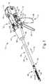
図1は、ハンドルアセンブリ(11)及び取り外し可能なシャフトアセンブリ(16)を含む、モータ駆動外科用切断及び締結器具(10)を示す。いくつかの変形例では、ハンドルアセンブリ(11)及びシャフトアセンブリ(16)は、それぞれ、単回使用の使い捨て構成要素が提供される。いくつかの他の変形例では、ハンドルアセンブリ(11)及びシャフトアセンブリ(16)は、それぞれ、再使用可能な構成要素として提供される。別の単なる例示的な実施例として、シャフトアセンブリ(16)は、単回使用の使い捨て構成要素として提供することができ、一方で、ハンドルアセンブリは、再使用可能な構成要素として提供される。本明細書の教示を考慮することで、再使用のために好適に再処理することができるハンドルアセンブリ(11)及びシャフトアセンブリ(16)の再使用可能な変形例が当業者に明らかになるであろう。I. Exemplary Surgical Instrument Overview FIG. 1 shows a motor driven surgical cutting and fastening instrument (10) including a handle assembly (11) and a removable shaft assembly (16). In some variations, the handle assembly (11) and shaft assembly (16) are each provided with a single-use, disposable component. In some other variations, the handle assembly (11) and shaft assembly (16) are each provided as a reusable component. As another merely illustrative example, the shaft assembly (16) may be provided as a single-use, disposable component, while the handle assembly is provided as a reusable component. Given the teachings herein, one of ordinary skill in the art will appreciate reusable variations of the handle assembly (11) and shaft assembly (16) that can be suitably reprocessed for reuse. Ah
本実施例のハンドルアセンブリ(11)は、筐体(12)と、閉鎖トリガ(32)と、発射トリガ(33)と、を含む。筐体(12)の少なくとも一部分は、臨床医が把持し、操作し、作動させるように構成されたハンドル(14)を形成する。筐体(12)は、シャフトアセンブリ(16)に動作可能に取り付けるように構成され、このシャフトアセンブリには、外科用エンドエフェクタ(18)が動作可能に連結される。下で説明するように、エンドエフェクタ(18)は、1つ以上の外科用タスク又は手術を実行するように構成される。具体的には、図1に示される例のエンドエフェクタ(18)は、従来のエンドカッターのエンドエフェクタに類似する様態で、外科用切断及びステープル留め手術を行うように動作可能であるが、これは、単なる1つの例示的な実施例にすぎないことを理解されたい。 The handle assembly (11) of this example includes a housing (12), a closure trigger (32), and a firing trigger (33). At least a portion of the housing (12) forms a handle (14) configured to be grasped, manipulated and actuated by a clinician. The housing (12) is configured to operably attach to a shaft assembly (16) to which a surgical end effector (18) is operably coupled. The end effector (18) is configured to perform one or more surgical tasks or operations, as described below. Specifically, the example end effector (18) shown in FIG. 1 is operable to perform surgical cutting and stapling operations in a manner similar to that of conventional end cutters. It should be understood that is only one exemplary embodiment.
図1は、交換式シャフトアセンブリ(16)がハンドルアセンブリ(11)に動作可能に連結された、外科用器具(10)を示す。図2、図3は、ハンドル(14)の筐体(12)への交換式シャフトアセンブリ(16)の取り付けを示す。ハンドル(14)は、ねじ、スナップ機構、接着剤などで相互接続することができる一対の相互接続可能なハンドル筐体セグメント(22、24)を含む。例示される構成では、ハンドル筐体セグメント(22、24)は、臨床医が把持及び操作することができるピストルグリップ部分(26)を形成するように協働する。以下で更に詳細に考察されるように、ハンドル(14)は、その中に複数の駆動システムを動作可能に支持し、それら駆動システムは、それに動作可能に取り付けられた交換式シャフトアセンブリ(16)の対応する部分に対して、様々な制御運動を生成及び適用するように構成されている。下で更に詳細に論じるように、トリガ(32、33)は、ハンドル(14)の駆動システムの少なくともいくつかを起動させるように、ピストルグリップ部分(26)に向かって枢動可能である。 FIG. 1 shows a surgical instrument (10) having a replaceable shaft assembly (16) operably coupled to a handle assembly (11). 2 and 3 show the mounting of the replaceable shaft assembly (16) on the housing (12) of the handle (14). The handle (14) includes a pair of interconnectable handle housing segments (22, 24) that can be interconnected with screws, snap mechanisms, adhesives, or the like. In the illustrated configuration, the handle housing segments (22, 24) cooperate to form a pistol grip portion (26) that can be grasped and manipulated by a clinician. As discussed in more detail below, the handle (14) operably supports a plurality of drive systems therein, the drive systems operatively attached to the replaceable shaft assembly (16). Are configured to generate and apply various control movements to corresponding parts of the. As discussed in more detail below, the triggers (32, 33) are pivotable towards the pistol grip portion (26) to activate at least some of the drive system of the handle (14).
ハンドルアセンブリ(11)内の駆動システムの少なくともいくつかは、最終的に、概略的に図5に示されるモータ(118)によって駆動される。本実施例では、モータ(118)は、ピストルグリップ部分(26)において位置付けられるが、モータ(118)は、任意の他の好適な位置に位置付けられ得ることを理解されたい。モータ(118)は、ハンドル(14)に固定された電池パック(110)から電力を受信する。本実施例では、図5に示されるように、電池パック(110)は、ハンドル(14)から取り外し可能である。いくつかの他の変形例において、電池パック(110)は、ハンドル(14)から取り外し可能でない。いくつかのこのような変形例において、電池パック(110)(又はその変形形態)は、ハンドル筐体セグメント(22、24)内に完全に収容される。モータ(118)及び電池パック(110)がとり得る様々な好適な形態は、本明細書の教示を考慮することで当業者に明らかになるであろう。 At least some of the drive systems within the handle assembly (11) are ultimately driven by the motor (118) shown schematically in FIG. In this example, the motor (118) is positioned in the pistol grip portion (26), but it should be understood that the motor (118) may be positioned in any other suitable position. The motor (118) receives power from the battery pack (110) fixed to the handle (14). In this embodiment, as shown in FIG. 5, the battery pack (110) can be removed from the handle (14). In some other variations, the battery pack (110) is not removable from the handle (14). In some such variations, the battery pack (110) (or variations thereof) is completely contained within the handle housing segment (22, 24). Various suitable forms that the motor (118) and battery pack (110) may take will be apparent to those of ordinary skill in the art in view of the teachings herein.
図5にも概略的に示されるように、制御回路(117)は、ハンドル(14)内に収容される。単なる例として、制御回路(117)は、本明細書の教示を考慮することで当業者に明らかになるであろうように、マイクロコントローラ及び/又は様々な他の構成要素を備えることができる。制御回路(117)は、制御アルゴリズムを駆動モータ(118)に記憶し、実行するように構成される。制御回路(117)はまた、ハンドルアセンブリ(11)の近位端部に位置付けられたグラフィカルユーザインターフェース(116)を駆動するようにも構成される。いくつかの変形例において、制御回路(117)は、シャフトアセンブリ(16)から1つ以上の信号を受信し、処理するように構成される。単なる例として、制御回路(117)は、その開示内容が参照により本明細書に組み込まれる、2015年10月1日に公開された、米国特許出願公開第2015/0272575号、名称「Surgical Instrument Comprising a Sensor System」の教示の少なくとも一部に従って、構成され、動作可能であり得る。制御回路(117)が構成され、動作可能であり得る他の好適な方法は、本明細書の教示を考慮することで当業者に明らかになるであろう。 The control circuit (117) is housed within the handle (14), as also schematically shown in FIG. By way of example only, the control circuit (117) may comprise a microcontroller and/or various other components, as will be apparent to those of ordinary skill in the art in view of the teachings herein. The control circuit (117) is configured to store and execute the control algorithm on the drive motor (118). The control circuit (117) is also configured to drive a graphical user interface (116) located at the proximal end of the handle assembly (11). In some variations, the control circuit (117) is configured to receive and process one or more signals from the shaft assembly (16). By way of example only, the control circuit (117) may include a control circuit (117), US Patent Application Publication No. 2015/0272575, published on October 1, 2015, the name of which is "Surgical Instrument Comprising," the disclosure of which is incorporated herein by reference. A Sensor System” may be constructed and operative in accordance with at least some of the teachings of “Sensor System”. Other suitable ways in which the control circuit (117) may be configured and operable will be apparent to those of ordinary skill in the art in view of the teachings herein.
図3で最もよく分かるように、ハンドル(14)のフレーム(28)は、複数の駆動システムを動作可能に支持する。この特定の例では、フレーム(28)は、全体として、(30)に指定される「第1の」又は閉鎖駆動システムを動作可能に支持し、この閉鎖駆動システムは、そこに動作可能に取り付けられた、又は連結された交換式シャフトアセンブリ(16)に閉鎖運動及び開放運動を適用するために用いることができる。また、この特定の例では、閉鎖駆動システム(30)は、フレーム(28)によって枢動可能に支持された閉鎖トリガ(32)の形態のアクチュエータを含む。より具体的には、閉鎖トリガ(32)は、ピン(図示せず)によって筐体(14)に枢動可能に連結される。このような構成は、閉鎖トリガ(32)が臨床医によって操作されることを可能にし、よって、臨床医がハンドル(14)のピストルグリップ部分(26)を把持したとき、閉鎖トリガ(32)を、開始位置又は「非作動」位置(図4A)からピストルグリップ部分(26)に向かって「作動」位置へと、より具体的には完全圧縮位置又は完全作動位置(図4B)へと容易に枢動させることができる。閉鎖トリガ(32)は、ばね又は他の付勢構成(図示せず)によって非作動位置へと付勢されてもよい。 As best seen in FIG. 3, the frame (28) of the handle (14) operably supports a plurality of drive systems. In this particular example, frame (28) operatively supports a "first" or closure drive system, designated generally at (30), to which closure drive system is operably mounted. It can be used to apply a closing movement and an opening movement to the attached or connected replaceable shaft assembly (16). Also, in this particular example, the closure drive system (30) includes an actuator in the form of a closure trigger (32) pivotally supported by the frame (28). More specifically, the closure trigger (32) is pivotally connected to the housing (14) by a pin (not shown). Such a configuration allows the closure trigger (32) to be manipulated by the clinician, thus opening the closure trigger (32) when the clinician grips the pistol grip portion (26) of the handle (14). Easily from the starting position or the "non-actuated" position (Fig. 4A) towards the pistol grip portion (26) to the "actuated" position, and more specifically to the fully compressed or fully actuated position (Fig. 4B). Can be pivoted. The closure trigger (32) may be biased to a non-actuated position by a spring or other biasing arrangement (not shown).
本実施例では、閉鎖駆動システム(30)は、閉鎖トリガ(32)に枢動可能に連結された閉鎖リンク機構アセンブリ(36)を更に含む。閉鎖リンク機構アセンブリ(36)の一部分を図3に示す。閉鎖リンク機構アセンブリ(36)は、ともにピン(図示せず)によって閉鎖トリガ(32)に枢動可能に連結された第1の閉鎖リンク(図示せず)と、第2の閉鎖リンク(38)と、を含むことができる。第2の閉鎖リンク(38)はまた、本明細書において、「取り付け部材」とも称され得るが、横方向取り付けピン(42)を含む。図3に示されるように、取り付けピン(42)は、シャフトアセンブリ(16)がハンドルアセンブリ(11)から取り外されたときに露出する。したがって、下で更に詳細に説明するように、取り付けピン(42)は、シャフトアセンブリ(16)がハンドルアセンブリ(11)に連結されたときに、シャフトアセンブリ(16)の相補的な機構と連結することができる。 In this example, the closure drive system (30) further includes a closure linkage assembly (36) pivotally coupled to the closure trigger (32). A portion of the closure linkage assembly (36) is shown in FIG. The closure linkage assembly (36) includes a first closure link (not shown) pivotally coupled to a closure trigger (32) together by a pin (not shown) and a second closure link (38). And can be included. The second closure link (38), which may also be referred to herein as a "mounting member", includes a lateral mounting pin (42). As shown in FIG. 3, the mounting pin (42) is exposed when the shaft assembly (16) is removed from the handle assembly (11). Thus, as described in more detail below, the mounting pin (42) couples with a complementary feature of the shaft assembly (16) when the shaft assembly (16) is coupled to the handle assembly (11). be able to.
更に図1〜図3を参照すると、第1の閉鎖リンク(図示せず)は、フレーム(28)に枢動可能に連結された閉鎖解放アセンブリ(44)と協働するように構成されている。少なくとも1つの例において、閉鎖解放アセンブリ(44)は、解放ボタンアセンブリ(46)を有し、遠位に突出するロッキングポール(図示せず)がその上に形成される。解放ボタンアセンブリ(46)は、解放ばね(図示せず)によって反時計回りの方向に枢動し得る。臨床医が閉鎖トリガ(32)をその非作動位置からハンドル(14)のピストルグリップ部分(26)に向かって押下すると、第1の閉鎖リンク(図示せず)は、ロッキングポール(図示せず)が第1の閉鎖リンク(図示せず)と保持係合する点に向かって上向きに枢動し、それにより、閉鎖トリガ(32)が非作動位置に戻ることを防ぐ。したがって、閉鎖解放アセンブリ(44)は、閉鎖トリガ(32)を完全作動位置でロックする働きをする。 Still referring to FIGS. 1-3, a first closure link (not shown) is configured to cooperate with a closure release assembly (44) pivotally coupled to the frame (28). .. In at least one example, the closure release assembly (44) has a release button assembly (46) with a distally projecting locking pole (not shown) formed thereon. The release button assembly (46) may be pivoted in a counterclockwise direction by a release spring (not shown). When the clinician depresses the closure trigger (32) from its non-actuated position towards the pistol grip portion (26) of the handle (14), the first closure link (not shown) causes the locking pole (not shown). Pivot upwards toward a point of retention engagement with the first closure link (not shown), thereby preventing the closure trigger (32) from returning to the inoperative position. Thus, the closure release assembly (44) serves to lock the closure trigger (32) in the fully activated position.
臨床医が閉鎖トリガ(32)を作動位置からロック解除して非作動位置に戻したいとき、臨床医は、単純に、閉鎖解放ボタンアセンブリ(46)を遠位に付勢することによって、閉鎖解放ボタンアセンブリ(46)を枢動させ、よって、ロッキングポール(図示せず)が第1の閉鎖リンク(図示せず)との係合から外れるように移動する。ロッキングポール(図示せず)が第1の閉鎖リンク(図示せず)との係合から外れるように移動するときに、弾性付勢が閉鎖トリガ(32)を非作動位置に戻すように付勢することに応答して、閉鎖トリガ(32)を非作動位置に戻すことができる。他の閉鎖トリガロック及び解放構成が用いられてもよい。 When the clinician wishes to unlock the closure trigger (32) from the actuated position back to the non-actuated position, the clinician simply urges the closure release button assembly (46) distally to close the closure release. Pivot the button assembly (46) and thus move the locking pole (not shown) out of engagement with the first closure link (not shown). When the locking pole (not shown) moves out of engagement with the first closure link (not shown), the elastic bias biases the closure trigger (32) back to the inoperative position. In response to doing so, the closure trigger (32) can be returned to the inoperative position. Other closure trigger lock and release configurations may be used.
交換式シャフトアセンブリ(16)は、シャフトアセンブリ(16)の長手方向軸に対して所望の位置にエンドエフェクタ(18)を解放可能に保持するように構成され得る、関節ジョイント(52)と関節ロック(図示せず)とを更に含む。本実施例では、関節ジョイント(52)は、当該技術分野で既知であるように、エンドエフェクタ(18)をシャフトアセンブリ(16)の長手方向軸から離れて横方向に偏向させることを可能にするように構成される。単なる例として、エンドエフェクタ(18)、関節ジョイント(52)、及び関節ロック(図示せず)は、2014年9月18日に公開された、米国特許出願公開第2014/0263541号、名称「Articulatable Surgical Instrument Comprising an Articulation Lock」の教示の少なくとも一部に従って、構成され、動作可能であり得る。 The replaceable shaft assembly (16) may be configured to releasably hold the end effector (18) in a desired position relative to the longitudinal axis of the shaft assembly (16) and the articulation joint (52) and articulation lock. (Not shown). In this example, the articulation joint (52) allows lateral deflection of the end effector (18) away from the longitudinal axis of the shaft assembly (16), as is known in the art. Is configured as follows. By way of example only, the end effector (18), the articulation joint (52), and the articulation lock (not shown) are disclosed in US Patent Application Publication No. 2014/0263541, entitled "Articulatable", published September 18, 2014. It may be constructed and operable in accordance with at least some of the teachings of Surgical Instrument Comprising and Articulation Lock.
本実施例では、関節ジョイント(52)の関節は、ハンドルアセンブリ(11)上の関節コントロールロッカー(112)を介した操作者からの制御入力に基づいて、モータ(118)を介してモータ駆動される。単なる例として、操作者が関節制御ロッカー(112)の上部分を押下したとき、エンドエフェクタ(18)は、関節ジョイント(52)において(器具(10)を上から見て)右へと横方向に枢動することができ、操作者が関節制御ロッカー(112)の下部分を押下したとき、エンドエフェクタ(18)は、関節ジョイント(52)において(器具(10)を上から見て)左へと横方向に枢動することができる。いくつかの変形例において、ハンドルアセンブリ(11)の他方の側部は、別の関節制御ロッカー(112)を含む。このような変形例において、ハンドルアセンブリ(11)の他方の側部上の関節制御ロッカー(112)は、関節制御ロッカー(112)の上への作動及び関節制御ロッカー(112)の下への作動に応答して、エンドエフェクタ(18)の上記の方向とは反対方向への枢動を提供するように構成することができる。単なる例として、関節ジョイント(52)においてエンドエフェクタ(18)の関節のモータ駆動を提供する関節制御ロッカー(112)及び残りの機構は、その開示内容が参照により本明細書に組み込まれる、2015年10月1日に公開された、米国特許出願公開第2015/0280384号、名称「Surgical Instrument Comprising a Rotatable Shaft」の教示の少なくとも一部に従って、構成され、動作可能であり得る。関節ジョイント(52)においてエンドエフェクタ(18)の関節のモータ駆動を提供する関節制御ロッカー(112)及び残りの機構が構成され、動作可能であり得る他の適切な方法は、本明細書の教示を考慮することで当業者に明らかになるであろう。 In this example, the joints of the joint joint (52) are motor driven via a motor (118) based on control input from an operator via a joint control rocker (112) on the handle assembly (11). It By way of example only, when the operator depresses the upper portion of the joint control rocker (112), the end effector (18) will move laterally to the right (as seen from above the instrument (10)) at the joint joint (52). The end effector (18) is left at the joint joint (52) (viewing the instrument (10) from above) when the operator depresses the lower portion of the joint control rocker (112). It can pivot laterally to. In some variations, the other side of the handle assembly (11) includes another articulation control rocker (112). In such a variation, the articulation control rocker (112) on the other side of the handle assembly (11) operates above and below the articulation control rocker (112). In response to, the end effector (18) may be configured to provide pivoting in a direction opposite to the above direction. By way of example only, the articulation control rocker (112) and the remaining features that provide motor drive for the articulation of the end effector (18) at the articulation joint (52), 2015, the disclosure of which is incorporated herein by reference. It may be constructed and operable in accordance with at least a portion of the teachings of US Patent Application Publication No. 2015/0280384, entitled "Surgical Instrument Comprising a Rotatable Shaft," published October 1. Other suitable ways in which the articulation control rocker (112) and the rest of the mechanism that provides motor drive for the joints of the end effector (18) at the articulation joint (52) may be configured and operable may be taught by the teachings herein. Will be apparent to those skilled in the art.
本実施例のエンドエフェクタ(18)は、ステープルカートリッジ(20)をその中で動作可能に支持するように構成された、細長いチャネル(48)の形態の下側ジョーを備える。本実施例のエンドエフェクタ(18)は、細長いチャネル(48)に対して枢動可能に支持された、アンビル(50)の形態の上側ジョーを更に含む。交換式シャフトアセンブリ(16)は、ノズル部分(56、58)から成る近位筐体又はノズル(54)と、エンドエフェクタ(18)の閉鎖及び/又は開放アンビル(50)に利用することができる閉鎖管(60)と、を更に含む。シャフトアセンブリ(16)はまた、閉鎖シャトル(62)をシャーシ(64)に対して軸方向に移動させることができるように、シャフトアセンブリ(16)のシャーシ(64)内で摺動可能に支持された閉鎖シャトル(62)も含む。閉鎖シャトル(62)は、第2の閉鎖リンク(38)に取り付けられた取り付けピン(42)への取り付けのために構成されている、近位に突出する一対のフック(66)を含む。閉鎖管(60)の近位端部(図示せず)は、それに対する相対的回転のために閉鎖シャトル(62)に連結されるが、閉鎖管(60)と閉鎖シャトル(62)との組み合わせは、閉鎖管(60)及び閉鎖シャトル(62)の互いの長手方向への移動を提供する。閉鎖ばね(図示せず)が閉鎖管(60)上に軸支され、閉鎖管(60)を近位方向(PD)に付勢する働きをし、それによって、シャフトアセンブリ(16)がハンドル(14)に動作可能に連結されたとき、閉鎖トリガ(32)を非作動位置へと枢動させる働きをし得る。 The end effector (18) of the present example comprises a lower jaw in the form of an elongated channel (48) configured to operably support the staple cartridge (20) therein. The end effector (18) of the present example further includes an upper jaw in the form of an anvil (50) pivotally supported with respect to the elongated channel (48). The replaceable shaft assembly (16) may be utilized for a proximal housing or nozzle (54) consisting of nozzle portions (56, 58) and for closing and/or opening anvil (50) of the end effector (18). And a closed tube (60). The shaft assembly (16) is also slidably supported within the chassis (64) of the shaft assembly (16) so that the closure shuttle (62) can be moved axially relative to the chassis (64). A closed shuttle (62) is also included. The closure shuttle (62) includes a pair of proximally projecting hooks (66) configured for attachment to attachment pins (42) attached to the second closure link (38). The proximal end (not shown) of the closure tube (60) is coupled to the closure shuttle (62) for relative rotation thereto, but the combination of the closure tube (60) and the closure shuttle (62). Provide longitudinal movement of the closure tube (60) and the closure shuttle (62) relative to each other. A closure spring (not shown) is pivotally mounted on the closure tube (60) and serves to bias the closure tube (60) in the proximal direction (PD), thereby causing the shaft assembly (16) to handle ( When operably coupled to 14), it may serve to pivot the closure trigger (32) to a non-actuated position.
本実施例では、関節ジョイント(52)は、二重枢軸閉鎖スリーブアセンブリ(70)を含む。二重枢軸閉鎖スリーブアセンブリ(70)は、その開示内容が参照により本明細書に組み込まれる、米国特許出願公開第2014/0263541に開示される様々な様態で開口タブをアンビル(50)に係合するための、エンドエフェクタ閉鎖スリーブアセンブリ(72)を含む。関節ジョイント(52)が関節動作状態であるとき(すなわち、エンドエフェクタ(18)が、関節ジョイント(52)においてシャフトアセンブリ(16)の長手方向軸から横方向に離れて枢動可能に偏向するとき)であっても、閉鎖トリガ(32)の枢動に応答して、二重枢軸閉鎖スリーブアセンブリ(70)が閉鎖管(60)と共に移動するように、二重枢軸閉鎖スリーブアセンブリ(70)が、閉鎖管(60)と連結されることを理解されたい。更に、エンドエフェクタ閉鎖スリーブアセンブリ(72)とアンビル(50)との係合は、二重枢軸閉鎖スリーブアセンブリ(70)及び閉鎖管(60)の遠位移動に応答した、アンビル(50)のステープルカートリッジ(20)に向かう枢動、及び二重枢軸閉鎖スリーブアセンブリ(70)及び閉鎖管(60)の近位移動に応答した、ステープルカートリッジ(20)から離れるアンビル(50)の枢動を提供する。本例のシャフトアセンブリ(16)は関節ジョイント(52)を含むが、他の交換式シャフトアセンブリは、関節動作能力を欠いていてもよい。 In this example, the articulating joint (52) includes a dual pivot closure sleeve assembly (70). A dual pivot closure sleeve assembly (70) engages an opening tab with an anvil (50) in various manners disclosed in US Patent Application Publication No. 2014/0263541, the disclosure of which is incorporated herein by reference. An end effector closure sleeve assembly (72) for When the articulating joint (52) is articulating (ie, when the end effector (18) pivotally deflects laterally away from the longitudinal axis of the shaft assembly (16) at the articulating joint (52). ), the dual pivot closure sleeve assembly (70) is adapted to move with the closure tube (60) in response to pivoting of the closure trigger (32). , Be connected to the closed tube (60). Further, engagement of the end effector closure sleeve assembly (72) with the anvil (50) is responsive to distal movement of the dual pivot closure sleeve assembly (70) and closure tube (60) staples of the anvil (50). Providing pivoting of the anvil (50) away from the staple cartridge (20) in response to pivoting toward the cartridge (20) and proximal movement of the dual pivot closure sleeve assembly (70) and closure tube (60). .. The shaft assembly (16) of this example includes an articulating joint (52), although other replaceable shaft assemblies may lack articulation capabilities.
図3に示されるように、シャーシ(64)は、フレーム(28)の遠位取り付けフランジ部分(78)内に形成された、対応するダブテールスロット(76)内に受容されるように適合された、シャーシ上に形成された一対の先細取り付け部分(74)を含む。各ダブテールスロット(76)は、取り付け部分(74)を中に着座的に受容するように、先細であってもよく、又は略V字形であってもよい。シャフト取り付けラグ(80)が、中間発射シャフト(82)の近位端上に形成される。したがって、交換式シャフトアセンブリ(16)がハンドル(14)に連結されたとき、シャフト取り付けラグ(80)は、長手方向駆動部材(86)の遠位端部に形成された発射シャフト取り付けクレードル(84)内に受容される。シャフト取り付けラグ(80)が発射シャフト取り付けクレードル(84)内に受容されたとき、中間発射シャフト(82)は、長手方向駆動部材(86)と共に長手方向に移動する。当該技術分野で知られているように、中間発射シャフト(82)が遠位に移動するとき、中間発射シャフト(82)がエンドエフェクタ(18)を作動させて、ステープルを組織に打ち込み、組織を切断する。単なる例として、エンドエフェクタ(18)のこの作動は、その開示内容が参照により本明細書に組み込まれる、米国特許出願公開第2015/0280384号に従って、及び/又は本明細書に引用される様々な他の参考文献の少なくとも一部の教示に従って実行することができる。 As shown in FIG. 3, the chassis (64) is adapted to be received within a corresponding dovetail slot (76) formed in the distal mounting flange portion (78) of the frame (28). , A pair of tapered mounting portions (74) formed on the chassis. Each dovetail slot (76) may be tapered or may be generally V-shaped to seatably receive the mounting portion (74) therein. A shaft mounting lug (80) is formed on the proximal end of the intermediate firing shaft (82). Thus, when the replaceable shaft assembly (16) is coupled to the handle (14), the shaft mounting lug (80) has a firing shaft mounting cradle (84) formed at the distal end of the longitudinal drive member (86). ) Is accepted within. When the shaft mounting lug (80) is received within the firing shaft mounting cradle (84), the intermediate firing shaft (82) moves longitudinally with the longitudinal drive member (86). As is known in the art, as the intermediate firing shaft (82) moves distally, the intermediate firing shaft (82) actuates the end effector (18) to drive the staples into the tissue and drive the tissue. Disconnect. By way of example only, this actuation of the end effector (18) is in accordance with U.S. Patent Application Publication No. 2015/0280384, the disclosure of which is incorporated herein by reference, and/or various other references cited herein. It may be practiced according to the teachings of at least some of the other references.
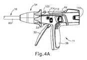
図4A〜図4Cは、エンドエフェクタ(18)の異なる作動状態の間のハンドルアセンブリ(11)の異なる状態を示す。図4Aでは、ハンドルアセンブリ(11)は、閉鎖トリガ(32)が非作動枢動位置にあり、かつ発射トリガ(33)が非作動枢動位置にある状態である。この段階で、エンドエフェクタ(18)は、アンビル(50)がステープルカートリッジ(20)から離れて枢動される、開放状態にある。 4A-4C show different states of the handle assembly (11) during different operating states of the end effector (18). In FIG. 4A, the handle assembly (11) is in the condition with the closure trigger (32) in the non-actuated pivot position and the firing trigger (33) in the non-actuated pivot position. At this stage, the end effector (18) is in the open condition, with the anvil (50) pivoted away from the staple cartridge (20).
図4Bでは、ハンドルアセンブリ(11)は、閉鎖トリガ(32)が作動枢動位置にある状態である。上で述べたように、閉鎖トリガ(32)は、操作者が解放ボタンアセンブリ(46)を作動させるまでこの位置にロックされる。この段階で、エンドエフェクタは、アンビル(50)がステープルカートリッジ(20)に向かって枢動される、閉鎖状態にあるが未発射状態であり、よって、組織は、アンビル(50)とカートリッジ(20)との間で圧縮されている。しかしながら、発射シャフト(82)は、まだステープルカートリッジ(20)からステープルを作動させるために遠位に駆動されておらず、発射シャフト(82)の遠位端部のナイフは、アンビル(20)とステープルカートリッジ(20)との間で組織をまだ切断していない。発射トリガ(33)は、非作動枢動位置から作動枢動位置への閉鎖トリガ(32)の移動のため、図4Bの部分的に作動した枢動位置にあることに留意されたい。しかしながら、発射トリガ(33)のこの移動は、操作者の発射トリガ(33)へのアクセスを向上させるためにのみ提供される。換言すれば、図4Aに示される位置から図4Bに示される位置への発射トリガ(33)のこの移動は、発射シーケンスをまだ起動させない。 In FIG. 4B, the handle assembly (11) has the closure trigger (32) in the actuated pivot position. As mentioned above, the closure trigger (32) is locked in this position until the operator actuates the release button assembly (46). At this stage, the end effector is in the closed but unfired state, with the anvil (50) pivoted towards the staple cartridge (20), so that the tissue is anvil (50) and cartridge (20). ) Is compressed between. However, the firing shaft (82) has not yet been driven distally to actuate staples from the staple cartridge (20) and the knife at the distal end of the firing shaft (82) is The tissue has not yet been cut with the staple cartridge (20). Note that firing trigger (33) is in the partially actuated pivot position of FIG. 4B due to the movement of closure trigger (32) from the non-actuated pivot position to the actuated pivot position. However, this movement of the firing trigger (33) is provided only to improve the operator's access to the firing trigger (33). In other words, this movement of the firing trigger (33) from the position shown in FIG. 4A to the position shown in FIG. 4B has not yet activated the firing sequence.
図4Cでは、ハンドルアセンブリは、閉鎖トリガ(32)が作動枢動位置のままであり、かつ発射トリガ(33)が作動枢動位置に枢動された状態にある。発射トリガ(33)のこの作動は、モータ(118)を起動させて、長手方向駆動部材(86)を長手方向に駆動し、次に、発射シャフト(82)を長手方向に駆動する。発射シャフト(82)の長手方向の移動は、アンビル(50)とステープルカートリッジ(20)との間で圧縮された組織の中への、ステープルカートリッジ(20)からのステープルの作動をもたらし、更に、アンビル(50)とステープルカートリッジ(20)の間で圧縮された組織の切断をもたらす。いくつかの変形例では、追加の安全トリガが提供される。例えば、追加の安全トリガは、安全トリガが作動するまで、発射トリガ(33)の作動を防ぐことができる。換言すれば、図4Bに示される状態に到達した後に、操作者が発射トリガ(33)を作動させる準備をしたとき、操作者は、最初に安全トリガを作動させ、次いで、発射トリガ(33)を作動させなければならない。安全トリガの存在が、発射トリガ(33)の不用意な作動を防ぎ得ることを理解されたい。 In FIG. 4C, the handle assembly is in a state where the closure trigger (32) remains in the actuated pivot position and the firing trigger (33) is pivoted to the actuated pivot position. This actuation of the firing trigger (33) actuates the motor (118) to drive the longitudinal drive member (86) longitudinally, which in turn drives the firing shaft (82) longitudinally. Longitudinal movement of the firing shaft (82) results in actuation of staples from the staple cartridge (20) into the tissue compressed between the anvil (50) and the staple cartridge (20), and Provides cutting of the compressed tissue between the anvil (50) and the staple cartridge (20). In some variations, additional safety triggers are provided. For example, an additional safety trigger may prevent firing of the firing trigger (33) until the safety trigger is activated. In other words, after reaching the condition shown in FIG. 4B, when the operator is ready to activate the firing trigger (33), the operator first activates the safety trigger and then the firing trigger (33). Must be activated. It should be appreciated that the presence of the safety trigger may prevent inadvertent activation of the firing trigger (33).
また、本実施例では、ステープルカートリッジ(20)に向かうアンビル(50)の作動は、単に機械的連結を通して閉鎖トリガ(32)とアンビル(50)との間に提供され、よって、アンビル(50)を作動させるためにモータ(118)を使用しないことも理解されたい。また、本実施例では、発射シャフト(82)の作動(したがって、ステープルカートリッジ(20)の作動)が、モータ(118)の起動を通して提供されることも理解されたい。加えて、関節ジョイント(52)の作動は、本実施例のモータ(118)の起動を通して提供される。関節ジョイント(52)のこのモータ駆動の作動は、駆動部材(86)の長手方向の移動を介して提供される。シャフトアセンブリ(16)内のクラッチアセンブリ(図示せず)は、駆動部材(86)の長手方向の移動と、関節ジョイント(52)を駆動するか又はステープルカートリッジ(20)を作動させるための機構とを選択的に連結するように動作可能である。このようなクラッチアセンブリを介した選択的な連結は、閉鎖トリガ(32)の枢動位置に基づく。具体的には、閉鎖トリガ(32)が図4Aに示される非作動位置にあるとき、(関節制御ロッカー(112)の起動に応答した)モータ(118)の起動が関節ジョイント(52)を駆動する。閉鎖トリガ(32)が図4Bに示される作動位置にあるとき、(発射トリガ(33)の作動に応答した)モータ(118)の起動がステープルカートリッジ(20)を作動させる。単なる例として、クラッチアセンブリは、その開示内容が参照により本明細書に組み込まれる、米国特許出願公開第2015/0280384号の教示の少なくともいくつかに従って、構成され、動作可能であり得る。 Also, in this embodiment, actuation of the anvil (50) towards the staple cartridge (20) is provided between the closure trigger (32) and the anvil (50) simply through mechanical coupling, thus the anvil (50). It should also be understood that the motor (118) is not used to operate the. It should also be appreciated that in this example, actuation of firing shaft (82) (and thus actuation of staple cartridge (20)) is provided through actuation of motor (118). Additionally, actuation of the articulated joint (52) is provided through the activation of the motor (118) of this example. This motor driven actuation of the articulated joint (52) is provided through the longitudinal movement of the drive member (86). A clutch assembly (not shown) within the shaft assembly (16) provides longitudinal movement of the drive member (86) and a mechanism for driving the articulating joint (52) or actuating the staple cartridge (20). Is operable to selectively connect. Selective engagement via such a clutch assembly is based on the pivoted position of the closure trigger (32). Specifically, activation of the motor (118) (in response to activation of the joint control rocker (112)) drives the joint joint (52) when the closure trigger (32) is in the inoperative position shown in FIG. 4A. To do. Activation of the motor (118) (in response to actuation of the firing trigger (33)) actuates the staple cartridge (20) when the closure trigger (32) is in the actuated position shown in FIG. 4B. By way of example only, a clutch assembly may be constructed and operable in accordance with at least some of the teachings of US Patent Application Publication No. 2015/0280384, the disclosure of which is incorporated herein by reference.
本実施例では、ハンドルアセンブリ(11)はまた、「ホーム」ボタン(114)も含む。単なる例として、アンビル(50)が閉鎖位置にあるとき、「ホーム」ボタン(114)は、モータ(118)を起動させて、駆動部材(86)を最近位の「ホーム」位置へと近位に後退させるように動作可能であり得る。加えて、又は代替的に、アンビル(50)が開放位置にあるときに、「ホーム」ボタン(114)は、モータ(118)を起動させて、関節ジョイント(52)を駆動して、非関節動作状態を達成し、よって、エンドエフェクタ(18)がシャフトアセンブリ(16)と同軸状に整列するように動作可能であり得る。加えて又は代替的に、「ホーム」ボタン(114)は、「ホーム」画面に戻るために、グラフィカルユーザインターフェース(116)を起動させ得る。本明細書の教示を考慮することで、「ホーム」ボタン(114)の起動に応答して提供され得る他の好適な動作が当業者に明らかになるであろう。 In this example, the handle assembly (11) also includes a "home" button (114). By way of example only, when the anvil (50) is in the closed position, the "home" button (114) activates the motor (118) to proximally drive the drive member (86) to the most proximal "home" position. May be operable to retract. Additionally or alternatively, when the anvil (50) is in the open position, the “home” button (114) activates the motor (118) to drive the articulated joint (52) to unarticulate. It may be operable to achieve an operational condition and thus the end effector (18) to be coaxially aligned with the shaft assembly (16). Additionally or alternatively, the “home” button (114) may activate the graphical user interface (116) to return to the “home” screen. Other suitable actions that may be provided in response to activation of the "home" button (114) will be apparent to those of ordinary skill in the art in view of the teachings herein.
本実施例のシャフトアセンブリ(16)は、連結シャフトアセンブリ(16)をハンドルアセンブリ(11)に、より具体的にはフレーム(28)に、取り外し可能に連結するためのラッチシステムを更に含む。単なる例として、このラッチシステムは、シャーシ(64)に移動可能に連結されたロックヨーク又は他の種類のロック部材を含むことができる。図3に示されるように、このようなロックヨークは、フレーム(28)内の対応するロックデテント又は溝(98)と解放可能に係合するように構成された2つの近位突出ロックラグ(96)を含むことができる。いくつかの変形例では、ロックヨークは、弾性部材(例えば、ばねなど)によって近位方向に付勢される。ロックヨークの作動は、シャーシ(64)に装着されたラッチアクチュエータアセンブリ(102)上に摺動可能に装着されたラッチボタン(100)によって達成することができる。ラッチボタン(100)は、ロックヨークに対して近位方向に付勢することができる。ロックヨークは、ラッチボタン(100)を遠位方向に付勢することによってアンロック位置へと移動させることができ、これはまた、ロックヨークを枢動させて、フレーム(28)との係合保持を解除する。ロックヨークがフレーム(28)との「係合保持」状態であるとき、ロックラグ(96)は、対応するロックデテント又は溝(98)内に係合して着座される。更なる単なる例として、シャフトアセンブリ(16)は、その開示内容が参照により本明細書に組み込まれる、2017年3月30日に公開された、米国特許出願公開第2017/0086823号、名称「Surgical Stapling Instrument with Shaft Release,Powered Firing,and Powered Articulation」の教示の少なくとも一部に従って、その開示内容が参照により本明細書に組み込まれる、米国特許出願公開第2015/0280384号の教示の少なくともいくつかに従って、及び/又は任意の他の好適な適切な様式で、ハンドルアセンブリ(11)と取り外し可能に連結され得る。 The shaft assembly (16) of this example further includes a latch system for releasably connecting the connecting shaft assembly (16) to the handle assembly (11), and more specifically to the frame (28). By way of example only, the latch system may include a locking yoke or other type of locking member movably coupled to the chassis (64). As shown in FIG. 3, such a locking yoke includes two proximal projecting locking lugs (96) configured to releasably engage corresponding locking detents or grooves (98) in the frame (28). ) Can be included. In some variations, the lock yoke is biased proximally by an elastic member (eg, a spring, etc.). Actuation of the lock yoke can be accomplished by a latch button (100) slidably mounted on a latch actuator assembly (102) mounted on the chassis (64). The latch button (100) can be biased proximally with respect to the lock yoke. The lock yoke can be moved to an unlocked position by biasing the latch button (100) distally, which also pivots the lock yoke to engage the frame (28). Release the hold. The lock lugs (96) are seated in engagement in the corresponding lock detents or grooves (98) when the lock yoke is in the "retaining engagement" state with the frame (28). By way of further example only, the shaft assembly (16) is disclosed in U.S. Patent Application Publication No. 2017/0086823, entitled "Surgical," published March 30, 2017, the disclosure of which is incorporated herein by reference. In accordance with at least some of the teachings of US Patent Application Publication No. 2015/0280384, in accordance with at least some of the teachings of "Stapling Instrument with Shaft Release, Powered Firing, and Powered Articulation," the disclosures of which are incorporated herein by reference. , And/or any other suitable suitable manner for releasably coupling with the handle assembly (11).
シャフトアセンブリ(16)とハンドルアセンブリ(11)との間の連結プロセスを開始するために、臨床医は、シャーシ(64)上に形成された先細取り付け部分(74)がフレーム(28)内のダブテールスロット(76)と整合されるように、フレーム(28)の上方に、又はそれに隣接して、交換式シャフトアセンブリ(16)のシャーシ(64)を位置付けることができる。次いで、臨床医は、シャフトアセンブリ(16)を、シャフトアセンブリ(16)の長手方向軸に垂直な取り付け軸(IA)に沿って移動させて、取り付け部分(74)を対応するダブテール受容スロット(76)と「動作可能な係合」で着座させることができる。その際、中間発射シャフト(82)上のシャフト取り付けラグ(80)も、長手方向に移動可能な駆動部材(86)のクレードル(84)内に着座され、第2の閉鎖リンク(38)上にあるピン(42)の部分が、閉鎖シャトル(62)内の対応するフック(66)内に着座される。本明細書で使用するとき、2つの構成要素の文脈における「動作可能な係合」という用語は、それら2つの構成要素が互いに十分に係合され、そのため、作動運動をそれらに適用すると、構成要素が、意図される行為、機能、及び/又は手順を実行し得ることを意味する。 To initiate the coupling process between the shaft assembly (16) and the handle assembly (11), the clinician has the advantage that the tapered attachment portion (74) formed on the chassis (64) has a dovetail within the frame (28). The chassis (64) of the replaceable shaft assembly (16) may be positioned above or adjacent to the frame (28) so that it is aligned with the slot (76). The clinician then moves the shaft assembly (16) along an attachment axis (IA) perpendicular to the longitudinal axis of the shaft assembly (16) to attach the attachment portion (74) to a corresponding dovetail receiving slot (76). ) And "operable engagement". The shaft mounting lug (80) on the intermediate firing shaft (82) is then also seated in the cradle (84) of the longitudinally displaceable drive member (86) and onto the second closure link (38). A portion of a pin (42) is seated in a corresponding hook (66) in the closure shuttle (62). As used herein, the term "operable engagement" in the context of two components means that the two components are in sufficient engagement with each other so that when an actuating motion is applied to them, the configuration An element is capable of performing the intended act, function, and/or procedure.
上で論じたように、交換式シャフトアセンブリ(16)の少なくとも5つのシステムが、ハンドル(14)の少なくとも5つの対応するシステムと動作可能に連結され得る。第1のシステムは、シャフトアセンブリ(16)のフレーム又はスパインをハンドル(14)のフレーム(28)と連結する、及び/又は整列させる、フレームシステムを備える。第2のシステムは、シャフトアセンブリ(16)をハンドル(14)に解放可能にロックする、ラッチシステムである。 As discussed above, at least five systems of the replaceable shaft assembly (16) may be operably coupled with at least five corresponding systems of the handle (14). The first system comprises a frame system that couples and/or aligns the frame or spine of the shaft assembly (16) with the frame (28) of the handle (14). The second system is a latch system that releasably locks the shaft assembly (16) to the handle (14).
第3のシステムは、ハンドル(14)の閉鎖トリガ(32)、及び閉鎖管(60)、及びシャフトアセンブリ(16)のアンビル(50)を動作可能に接続することができる、閉鎖駆動システム(30)である。上で概説したように、シャフトアセンブリ(16)の閉鎖シャトル(62)は、第2の閉鎖リンク(38)上にあるピン(42)と係合する。閉鎖駆動システム(30)を通して、アンビル(50)は、閉鎖トリガ(32)のピストルグリップ(26)に向かう、及びそこから離れる枢動に基づいて、ステープルカートリッジ(20)に向かって、及びそこから離れて枢動する。 The third system is capable of operatively connecting the closure trigger (32) of the handle (14) and the closure tube (60), and the anvil (50) of the shaft assembly (16). ). As outlined above, the closure shuttle (62) of the shaft assembly (16) engages the pin (42) on the second closure link (38). Through the closure drive system (30), the anvil (50) is directed toward and away from the staple cartridge (20) based on pivoting toward and away from the pistol grip (26) of the closure trigger (32). Pivot away.
第4のシステムは、ハンドル(14)の発射トリガ(33)とシャフトアセンブリ(16)の中間発射シャフト(82)とを動作可能に接続する、関節及び発射駆動システムである。上で概説したように、シャフト取り付けラグ(80)は、長手方向駆動部材(86)のクレードル(84)と動作可能に接続する。この第4のシステムは、閉鎖トリガ(32)の枢動位置に応じて、関節ジョイント(52)又はステープルカートリッジ(20)のモータ駆動の作動を提供する。閉鎖トリガ(32)が非作動枢動位置にあるとき、第4のシステムは、関節制御ロッカー(112)を関節ジョイント(52)と動作可能に接続し、それにより、関節ジョイント(52)におけるシャフトアセンブリ(11)の長手方向軸に向かう、及びそこから離れるエンドエフェクタ(18)のモータ駆動の枢動偏向を与える。閉鎖トリガ(32)が作動枢動位置にあるとき、第4のシステムは、発射トリガ(33)をステープルカートリッジ(20)と動作可能に接続し、発射トリガ(33)の作動に応答して、アンビル(50)とステープルカートリッジ(20)との間に捕捉された組織のステープル留め及び切断をもたらす。 The fourth system is an articulation and firing drive system that operatively connects the firing trigger (33) of the handle (14) and the intermediate firing shaft (82) of the shaft assembly (16). As outlined above, the shaft mounting lug (80) is operably connected to the cradle (84) of the longitudinal drive member (86). This fourth system provides motor driven actuation of the articulated joint (52) or staple cartridge (20) depending on the pivoted position of the closure trigger (32). A fourth system operably connects the articulation control rocker (112) with the articulation joint (52) when the closure trigger (32) is in the non-actuated pivot position, thereby providing a shaft at the articulation joint (52). A motor driven pivotal deflection of the end effector (18) towards and away from the longitudinal axis of the assembly (11) is provided. A fourth system operably connects the firing trigger (33) with the staple cartridge (20) when the closure trigger (32) is in the actuated pivot position, and in response to actuation of the firing trigger (33). Provides stapling and cutting of captured tissue between the anvil (50) and the staple cartridge (20).
第5のシステムは、シャフトアセンブリ(16)がハンドル(14)と動作可能に係合されたことをハンドル(14)の制御回路(117)に信号で伝えて、シャフトアセンブリ(16)とハンドル(14)との間で通電する、及び/又は信号を通信する、電気システムである。本実施例では、図3に示されるように、シャフトアセンブリ(16)は、シャフト回路基板(図示せず)に動作可能に装着された電気コネクタ(106)を含む。電気コネクタ(106)は、ハンドル制御基板(図示せず)上の対応する電気コネクタ(108)と嵌合係合するように構成される。回路及び制御システムに関する更なる詳細は、その開示内容が参照により本明細書に組み込まれる、米国特許出願公開第2014/0263541号、及び/又はその開示内容が参照により本明細書に組み込まれる、米国特許出願公開第2015/0272575号に見出すことができる。 A fifth system signals to the control circuit (117) of the handle (14) that the shaft assembly (16) has been operably engaged with the handle (14) to provide the shaft assembly (16) and the handle (14). 14) An electrical system that energizes and/or communicates signals with. In this example, as shown in FIG. 3, the shaft assembly (16) includes an electrical connector (106) operably mounted on a shaft circuit board (not shown). The electrical connectors (106) are configured for mating engagement with corresponding electrical connectors (108) on the handle control board (not shown). Further details regarding circuits and control systems can be found in US Patent Application Publication No. 2014/0263541, the disclosure of which is incorporated herein by reference, and/or the disclosure of which is incorporated herein by reference, US It can be found in Patent Application Publication No. 2015/0272575.
ハンドル(14)の対応するシステムと動作可能に連結することができる交換式シャフトアセンブリ(16)の他の種類のシステムは、本明細書の教示を考慮することで当業者に明らかになるであろう。 Other types of systems of interchangeable shaft assemblies (16) that can be operably coupled to corresponding systems of handle (14) will be apparent to those of ordinary skill in the art in view of the teachings herein. Let's do it.
上で述べたように、本実施例のハンドルアセンブリ(11)は、グラフィカルユーザインターフェース(116)を含む。単なる例として、グラフィカルユーザインターフェース(116)を使用して、電池(110)の動作状態、エンドエフェクタ(18)の動作状態、関節ジョイント(52)の動作状態、トリガ(32、33)の動作状態に関する様々な情報、及び/又は任意の他の種類の情報を表示することができる。グラフィカルユーザインターフェースを介して表示することができる他の適切な種類の情報は、本明細書の教示を考慮することで当業者に明らかになるであろう。 As mentioned above, the handle assembly (11) of this embodiment includes a graphical user interface (116). By way of example only, using the graphical user interface (116), the operating state of the battery (110), the operating state of the end effector (18), the operating state of the joint joint (52), the operating state of the trigger (32, 33). Various information regarding and/or any other type of information may be displayed. Other suitable types of information that can be displayed via a graphical user interface will be apparent to those of ordinary skill in the art in view of the teachings herein.
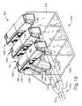
ハンドルアセンブリ(11)は、異なるサイズ及び種類のステープルカートリッジを支持するように適合されたエンドエフェクタを含み、異なるシャフト長、サイズ、及び種類等を有する交換式シャフトアセンブリと接続して使用するように構成することができる。単なる例として、図6は、ハンドルアセンブリ(11)と共に使用することができる様々な異なる種類のシャフトアセンブリ(16、120、130、140)を示す。具体的には、図6は、円形ステープル留め動作(例えば、端々吻合)を実行するように動作可能であるエンドエフェクタ(122)を有する円形ステープラシャフトアセンブリ(120)、線形ステープル留め動作を実行するように動作可能であるエンドエフェクタ(132)を有するライナステープラシャフトアセンブリ(130)、及びエンドエフェクタ(18)と同じ種類のステープル留め及び切断動作を行うように動作可能であるエンドエフェクタ(142)を有する第2のエンドカッターシャフトアセンブリ(140)を示す。しかしながら、この実施例では、シャフトアセンブリ(140)は、シャフトアセンブリ(16)よりも短く、シャフトアセンブリ(140)は、シャフトアセンブリ(16)よりも直径が小さく、エンドエフェクタ(142)は、エンドエフェクタ(18)よりも小さい。これらの様々な外科用ステープル留めシャフトアセンブリ(16、120、130、140)は、単なる例示的な実施例にすぎないことを理解されたい。 The handle assembly (11) includes an end effector adapted to support staple cartridges of different sizes and types, for use in connection with replaceable shaft assemblies having different shaft lengths, sizes, types and the like. Can be configured. By way of example only, FIG. 6 illustrates various different types of shaft assemblies (16, 120, 130, 140) that may be used with the handle assembly (11). Specifically, FIG. 6 illustrates a circular stapler shaft assembly (120) having an end effector (122) operable to perform a circular stapling operation (eg, end-to-end anastomosis), performing a linear stapling operation. A liner stapler shaft assembly (130) having an end effector (132) operable to perform an end effector (142) operable to perform the same type of stapling and cutting operation as the end effector (18). FIG. 6B shows a second end cutter shaft assembly (140) having. However, in this example, the shaft assembly (140) is shorter than the shaft assembly (16), the shaft assembly (140) is smaller in diameter than the shaft assembly (16), and the end effector (142) is an end effector. It is smaller than (18). It should be appreciated that these various surgical stapling shaft assemblies (16, 120, 130, 140) are merely exemplary examples.
また、制御回路(117)は、ハンドルアセンブリ(11)と連結されているシャフトアセンブリ(16、120、130、140)の種類を検出し、その特定の種類のシャフトアセンブリ(16、120、130、140)に好適な制御アルゴリズムを選択するように構成され得ることも理解されたい。別の単なる例示的な実施例として、各シャフトアセンブリ(16、120、130、140)は、その特定の種類のシャフトアセンブリ(16、120、130、140)に好適な制御アルゴリズムを記憶するチップ又は他のメモリデバイスを有することができ、制御回路(117)は、シャフトアセンブリ(16、120、130、140)がハンドルアセンブリ(11)と連結された後に、その制御アルゴリズムを受信及び実行することができる。 The control circuit (117) also detects the type of shaft assembly (16, 120, 130, 140) connected to the handle assembly (11) and detects the particular type of shaft assembly (16, 120, 130, 140). It should also be understood that it may be configured to select a suitable control algorithm for 140). As another merely illustrative example, each shaft assembly (16, 120, 130, 140) may include a chip or chip that stores a control algorithm suitable for that particular type of shaft assembly (16, 120, 130, 140). Other memory devices may be included and the control circuit (117) may receive and execute its control algorithm after the shaft assembly (16, 120, 130, 140) is coupled to the handle assembly (11). it can.
加えて、ハンドルアセンブリ(11)はまた、例えば、高周波(RF)エネルギー、超音波エネルギー及び/又は運動などの他の運動及び種類のエネルギーを、様々な外科用途及び手術に関連して使用するように適合されたエンドエフェクタ構成に印加するように構成されたアセンブリを含む、様々な他の交換式シャフトアセンブリと共に効果的に用いることもできる。更に、エンドエフェクタ、シャフトアセンブリ、ハンドル、外科用器具及び/又は外科用器具システムは、任意の好適な締結具(複数可)を利用して組織を締結することができる。例えば、中に着脱可能に格納された複数の締結具を備える締結具カートリッジが、シャフトアセンブリのエンドエフェクタに着脱可能に挿入及び/又は装着され得る。そのようなカートリッジの様々な例は、本明細書に列挙される様々な参考文献に開示されている。 In addition, the handle assembly (11) is also adapted to use other motions and types of energy, such as radio frequency (RF) energy, ultrasonic energy and/or motion, in connection with various surgical applications and procedures. It can also be effectively used with a variety of other replaceable shaft assemblies, including assemblies configured to apply to end effector configurations adapted to. Further, the end effector, shaft assembly, handle, surgical instrument and/or surgical instrument system can utilize any suitable fastener(s) to fasten tissue. For example, a fastener cartridge that includes a plurality of fasteners that are removably stored therein can be removably inserted and/or loaded into an end effector of a shaft assembly. Various examples of such cartridges are disclosed in the various references listed herein.
本明細書に開示される様々なシャフトアセンブリ(16)は、ハンドル付きのアセンブリ(11)内の制御回路(117)との電気通信を必要とするセンサ及び他の様々な構成要素を用いることができる。電気通信は、電気コネクタ(106、108)を嵌合させることを介して提供することができる。単なる例として、このようなセンサ及び他の構成要素は、その開示内容が参照により本明細書に組み込まれる、米国特許出願公開第2015/0272575号の教示の少なくともいくつかに従って構築され、動作可能であり得る。加えて又は代替的に、器具(10)は、本明細書に列挙される他の様々な参考文献のうちのいずれかの教示の少なくとも一部に従って構築され、かつ動作可能であってもよい。 The various shaft assemblies (16) disclosed herein may employ sensors and various other components that require electrical communication with the control circuit (117) within the assembly (11) with the handle. it can. Telecommunications can be provided through mating electrical connectors (106, 108). By way of example only, such sensors and other components may be constructed and operated in accordance with at least some of the teachings of US Patent Application Publication No. 2015/0272575, the disclosure of which is incorporated herein by reference. possible. Additionally or alternatively, instrument (10) may be constructed and operable in accordance with at least some of the teachings of any of the various other references listed herein.
本明細書に開示される様々な教示が、ロボット制御式外科用システムと接続して、効果的に利用することができることを理解するであろう。したがって、「筐体」又は「本体」という用語はまた、本明細書に開示される交換式シャフトアセンブリ及びそれらのそれぞれの同等物を作動させるために使用することができる、少なくとも1つの制御運動を生成及び適用するように構成された少なくとも1つの駆動システムを収容するか又は別様に動作可能に支持する、ロボットシステムの筐体又は同様の部分も包含することができる。「フレーム」という用語は、手持ち式外科用器具の一部分を指してもよい。「フレーム」という用語はまた、ロボット制御式の外科用器具の一部分、及び/又は外科用器具を動作可能に制御するために使用され得るロボットシステムの一部分も表すことができる。単なる例として、本明細書に開示される交換式シャフトアセンブリは、その開示内容が参照により本明細書に組み込まれる、2015年7月7日に発行された、米国特許第9,072,535号、名称「Surgical Stapling Instruments with Rotatable Staple Deployment Arrangements」に開示される、様々なロボットシステム、器具、構成要素、及び方法のいずれかと共に用いることができる。 It will be appreciated that the various teachings disclosed herein can be effectively utilized in connection with robotic controlled surgical systems. Thus, the term "housing" or "body" also refers to at least one control movement that can be used to actuate the replaceable shaft assemblies and their respective equivalents disclosed herein. A housing or similar portion of a robot system that houses or otherwise operably supports at least one drive system configured to generate and apply may also be included. The term "frame" may refer to a portion of a handheld surgical instrument. The term "frame" can also refer to a portion of a robot-controlled surgical instrument and/or a portion of a robotic system that may be used to operably control the surgical instrument. By way of example only, the replaceable shaft assembly disclosed herein is US Pat. No. 9,072,535 issued Jul. 7, 2015, the disclosure of which is incorporated herein by reference. , Any of the various robotic systems, instruments, components, and methods disclosed in the name "Surgical Stapling Instruments with Rotatable Staples Deployment Arrangements".
II.独立した集積回路を有する電池パックを備える外科用器具
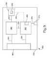
上述したように、ハンドルアセンブリ(11)は、電池パック(110)と、制御回路(117)と、閉鎖トリガー(32)を含む第1の駆動システム(30)と、中間発射シャフト(82)を長手方向に駆動するように構成されたモータ(118)と、を含む。電池パック(110)は、モータ(118)に電力を供給するように構成され、一方、制御回路(117)は、モータ(118)を駆動するために制御アルゴリズムを記憶及び実行するように構成されている。第1の駆動システム(30)の閉鎖トリガー(32)の枢動位置に応じて、モータ(118)は、制御ロッカー(112)(図4Aに示される位置)、又は発射トリガ(33)(図4B及び図4Cに示される位置)によって駆動されてもよい。したがって、制御回路(117)が制御ロッカー(112)又は発射トリガ(33)のいずれかにモータ(118)を作動させることを可能にするように、第1の駆動システム(30)が制御回路(117)と通信状態にあってもよい。II. Surgical Instrument Comprising a Battery Pack with Separate Integrated Circuits As described above, the handle assembly (11) includes a battery pack (110), a control circuit (117), and a first drive including a closure trigger (32). A system (30) and a motor (118) configured to longitudinally drive the intermediate firing shaft (82). The battery pack (110) is configured to power the motor (118), while the control circuit (117) is configured to store and execute a control algorithm to drive the motor (118). ing. Depending on the pivoted position of the closure trigger (32) of the first drive system (30), the motor (118) may be either a control rocker (112) (position shown in Figure 4A), or a firing trigger (33) (Figure 4B and the position shown in FIG. 4C). Thus, the first drive system (30) controls the control circuit (117) to enable the control circuit (117) to activate the motor (118) to either the control rocker (112) or the firing trigger (33). 117).
制御回路(117)は、制御回路(117)が上記の機能を実行し得るように、電池パック(110)から電力を引き出すように構成されてもよい。更に、制御回路(117)は、モータ(118)を駆動するための制御アルゴリズムを記憶及び実行するように構成されているため、制御回路(117)は、モータ(118)にいつ電力を供給するかを電池パック(110)に指示し得る。したがって、制御回路(117)は、電池パック(110)から電力を引き出して、制御回路(117)自身と、モータ(118)と、例えばグラフィカルユーザインターフェース(116)のような、ハンドルアセンブリ(11)の他の好適な構成要素とに電力を供給することができる。 The control circuit (117) may be configured to draw power from the battery pack (110) so that the control circuit (117) can perform the functions described above. Further, the control circuit (117) is configured to store and execute a control algorithm for driving the motor (118) such that the control circuit (117) powers the motor (118) at any time. This may be indicated to the battery pack (110). Thus, the control circuit (117) draws power from the battery pack (110) to control circuit (117) itself, the motor (118) and the handle assembly (11), such as a graphical user interface (116). Power to other suitable components of the.
制御回路(117)はまた、ハンドルアセンブリ(11)を「スリープモード」に入らせたり、その「スリープモード」を制御するように構成されてもよい。スリープモードでは、制御回路(117)は、グラフィックユーザインターフェース(116)及びモータ(118)への電力供給などのいくつかの機能を実行することを停止することができ、それによって、非スリープモードでの動作と比較して、電池パック(110)のエネルギー消耗を低下させる。しかしながら、制御回路(117)は、制御回路(117)がそれ自体のスリープモードを制御しているとき、電池パック(110)のエネルギーを依然として幾分か消耗させ得る。単なる一例として、制御回路(117)はそれ自体のスリープモードを制御することができるため、制御回路(117)は電池パック(110)のエネルギーを依然として幾分か使って、ホームボタン(114)又は制御ロッカー(112)を押すなどの一般的又は特定のユーザ入力に応答して、制御回路(117)が完全に再起動される可能性に対して制御回路(117)がいつも備えておくことができる。 The control circuit (117) may also be configured to cause the handle assembly (11) to enter and control the "sleep mode". In sleep mode, the control circuit (117) may stop performing some functions, such as powering the graphic user interface (116) and the motor (118), thereby causing the non-sleep mode. The energy consumption of the battery pack (110) is reduced as compared with the above operation. However, the control circuit (117) may still consume some energy of the battery pack (110) when the control circuit (117) is controlling its own sleep mode. By way of example only, the control circuit (117) may control its own sleep mode so that the control circuit (117) still uses some of the energy of the battery pack (110) to cause the home button (114) or The control circuit (117) may always be prepared for the possibility that the control circuit (117) may be completely restarted in response to general or specific user input such as pressing the control rocker (112). it can.
本明細書における教示を鑑みると、当業者に明白であろうと思われる任意の好適な理由により、制御回路(117)は自身のスリープモードに入り得る。例えば、制御回路(117)が、所定の期間内に様々なソースからいかなるユーザ入力/命令をも受信しない場合には、制御回路(117)はスリープモードになってよい。別の例として、制御回路(117)は、ホームボタン(114)を所定の時間押し続けるなどの特定のユーザ入力に応答してスリープモードになってもよい。更に別の例として、制御回路(117)は、モーションセンサ(例えば、加速度計など)からの入力がない状態で所定の時間経過後に、スリープモードに入ってもよい。 The control circuit (117) may enter its sleep mode for any suitable reason, as would be apparent to one of ordinary skill in the art in view of the teachings herein. For example, if the control circuit (117) does not receive any user input/command from various sources within a predetermined period of time, the control circuit (117) may be in sleep mode. As another example, the control circuit (117) may enter a sleep mode in response to certain user input, such as pressing and holding the home button (114) for a predetermined time. As yet another example, the control circuit (117) may enter the sleep mode after a lapse of a predetermined time with no input from the motion sensor (eg, accelerometer).
制御回路(117)は、制御回路(117)がそれ自体のスリープモードに入り、それを制御するときに、電池パック(110)内に蓄積されたエネルギーを不必要に消耗し得るため、ハンドルアセンブリ(11)の制御回路(117)に対して自律的に機能し得る、自前の独立した回路機構を有する代替的な電池パックを提供することが有益であり得る。そのような代替的な電池パックの独立した回路機構は、上述の電池パック(110)のように、制御回路(117)が、電池パックがハンドルアセンブリ(11)に電力をいつ供給するかを指示することを可能にするのではなくむしろ、ある電池パックがそれ自体の回路機構及び制御回路(117)に電力をいつ供給するかを、その電池パック自身が制御することを可能にし得る。同様に、独立した回路を有する代替的な電池パックは、その電池パックがモータ(118)、グラフィカルユーザインターフェース(116)、又はハンドルアセンブリ(11)の他の好適な構成要素に電力をいつ供給するかを制御してもよい。換言すれば、代替的な電池パックは、ハンドルアセンブリ(11)に対して独立してシャットダウンされてもよく、あるいは独立して、それ自体の「スリープモード」に入ったり、それ自体の「スリープモード」を制御したりすることができる。したがって、代替的な電池パックは、制御回路(117)が、代替的な電池パックの電源を不必要に消耗させることを防止することができる。更に、代替的な電池パックの独立した回路機構は、制御回路(117)と通信して、情報を更に交換することができる。代替的な電池パックの例については以下に詳述するが、本明細書の教示を考慮することで更なる例が当業者には明らかとなるであろう。 The control circuit (117) may unnecessarily drain the energy stored in the battery pack (110) as the control circuit (117) enters and controls its own sleep mode, thus the handle assembly. It may be beneficial to provide an alternative battery pack that has its own independent circuitry that can function autonomously with respect to control circuit (117) of (11). The independent circuitry of such an alternative battery pack, like the battery pack (110) described above, allows the control circuit (117) to indicate when the battery pack powers the handle assembly (11). Rather, it may allow the battery pack itself to control when it supplies power to its own circuitry and control circuitry (117). Similarly, an alternative battery pack with independent circuitry will provide power to the motor (118), graphical user interface (116), or other suitable component of the handle assembly (11) when the battery pack is powered. May be controlled. In other words, the alternative battery pack may be shut down independently of the handle assembly (11), or independently into its own "sleep mode" or its own "sleep mode". Can be controlled. Therefore, the alternative battery pack can prevent the control circuit (117) from unnecessarily exhausting the power source of the alternative battery pack. Moreover, the independent circuitry of the alternative battery pack can communicate with the control circuit (117) to further exchange information. Examples of alternative battery packs are detailed below, but further examples will be apparent to one of ordinary skill in the art in view of the teachings herein.
A.例示的な代替的ハンドルアセンブリ及び電池パックアセンブリ
図7A〜図8は、上述のハンドルアセンブリ(11)の代わりに、外科用器具(10)に容易に組み込まれ得る、例示的なハンドルアセンブリ(200)及び相補的な電池パックアセンブリ(300)を示す。ハンドルアセンブリ(200)は、後述する違いを除いて、上述したハンドルアセンブリ(11)と実質的に同様である。同様に、電池パックアセンブリ(300)は、後述する違いを除いて、上述した電池パック(110)と実質的に同様である。以下により詳細に記載されるように、電池パックアセンブリ(300)は、電池パックアセンブリ(300)がハンドルアセンブリ(200)に電力をいつ供給するか、それ自体のスリープモードにいつ入るか、及び/又はハンドルアセンブリ(200)といつ通信するかを制御する、それ自体の独立した制御回路(317)を含む。A. Exemplary Alternative Handle Assembly and Battery Pack Assembly FIGS. 7A-8 illustrate an exemplary handle assembly (200) that may be readily incorporated into a surgical instrument (10) in place of the handle assembly (11) described above. And a complementary battery pack assembly (300). The handle assembly (200) is substantially similar to the handle assembly (11) described above, except for the differences described below. Similarly, the battery pack assembly (300) is substantially similar to the battery pack (110) described above, except for the differences described below. As described in more detail below, the battery pack assembly (300) includes when the battery pack assembly (300) powers the handle assembly (200), when it enters its own sleep mode, and/or Alternatively, it includes its own independent control circuit (317) that controls when to communicate with the handle assembly (200).
ハンドルアセンブリ(200)は、電池連結アセンブリ(210)を含み、電池パックアセンブリ(300)はハンドル連結アセンブリ(310)を含む。電池連結アセンブリ(210)及びハンドル連結アセンブリ(310)は、電池パックアセンブリ(300)及びハンドルアセンブリ(200)が互いに動作可能に係合して、電池パックアセンブリ(300)がハンドルアセンブリ(200)の好適な構成要素に電力を供給し得るようにすることを可能にするように構成されている。したがって、電池パックアセンブリ(300)及びハンドルアセンブリ(200)が連結アセンブリ(210、310)を介して動作可能な係合を解除されると、電池パックアセンブリ(300)は、ハンドルアセンブリ(200)の好適な構成要素に電力を供給することを防止され得る。連結アセンブリ(210、310)は、動作可能な係合のために用いられる、本明細書の教示を考慮することで当業者には明らかとなる任意の好適な機能部を含み得る。例えば、連結アセンブリ(210、310)は、ハンドルアセンブリ(11)とシャフトアセンブリ(16)との間の電気通信を確立するために使用される、上述の電気コネクタ(106、108)と同様の電気コネクタを含んでもよい。 The handle assembly (200) includes a battery coupling assembly (210) and the battery pack assembly (300) includes a handle coupling assembly (310). The battery connection assembly (210) and the handle connection assembly (310) are operatively engaged with each other by the battery pack assembly (300) and the handle assembly (200) such that the battery pack assembly (300) is the handle assembly (200). It is adapted to allow the suitable components to be powered. Thus, when the battery pack assembly (300) and the handle assembly (200) are operatively disengaged via the coupling assemblies (210, 310 ), the battery pack assembly (300) may disengage from the handle assembly (200 ). It may be prevented to supply power to suitable components. Coupling assembly (210, 310) may include any suitable features used for operative engagement that will be apparent to those of ordinary skill in the art in view of the teachings herein. For example, the coupling assembly (210, 310) may be an electrical connector similar to the electrical connectors (106, 108) described above used to establish electrical communication between the handle assembly (11) and the shaft assembly (16). It may include a connector.
本明細書の教示を考慮することで当業者には明らかとなるように、ハンドルアセンブリ(200)及び電池パックアセンブリ(300)はまた、互いに機械的に取り付けられるための任意の好適な機構(例えば、ラッチなど)を含んでもよい。図7A及び図7Bに示されるように、本実施例では、電池パックアセンブリ(300)は、ハンドルアセンブリ(200)に対して、それぞれの連結アセンブリ(310、210)を介して、機械的に着脱され得る。しかしながらいくつかの他の変形例においては、電池パックアセンブリ(300)はハンドルアセンブリ(200)から取り外し可能ではない。いくつかのそのような変形例では、電池パックアセンブリ(300)(又はその変形形態)は、ハンドルアセンブリ(200)の筐体(212)に固着されるか、又は筐体(212)に永久的に固定されるか若しくは筐体(212)内に完全に収容されるように構成されている。同様に、本明細書の教示を考慮すれば、電池パックアセンブリ(300)をハンドルアセンブリ(200)と連結し得る様々な適切な方法が、当業者に明らかであろう。 The handle assembly (200) and battery pack assembly (300) may also be of any suitable mechanism for mechanically attaching to each other (eg, as will be apparent to those of skill in the art in view of the teachings herein). , Latches, etc.). As shown in FIGS. 7A and 7B, in the present embodiment, the battery pack assembly (300) is mechanically attached to and detached from the handle assembly (200) via the respective connecting assemblies (310, 210). Can be done. However, in some other variations, the battery pack assembly (300) is not removable from the handle assembly (200). In some such variations, the battery pack assembly (300) (or variations thereof) is affixed to the housing (212) of the handle assembly (200) or is permanently attached to the housing (212). It is fixed to the housing or is completely housed in the housing (212). Similarly, various suitable methods for coupling the battery pack assembly (300) with the handle assembly (200) will be apparent to those of ordinary skill in the art in view of the teachings herein.
電池連結アセンブリ(210)に加えて、ハンドルアセンブリ(200)は、筐体(212)と、制御回路(217)と、第1の駆動システム(230)と、第2の駆動システム(250)と、シャフト連結アセンブリ(220)と、を更に含む。筐体(212)は、上述した筐体(12)と実質的に類似のものである。制御回路(217)は、後述する違いを除いて、上述した制御回路(117)と実質的に同様である。したがって、制御回路(217)は、制御アルゴリズムを記憶及び実行したり、グラフィカルユーザインターフェースを駆動したり、接続されたシャフトアセンブリ(16)と通信したり、あるいは制御回路(117)に関する上記の任意の他の好適な機能を発揮してもよい。制御回路(217)は、電池パックアセンブリ(300)から電力を受け取り、かつ/又は電池パックアセンブリ(300)と通信することができるように、電気接続部(204)を介して電池連結アセンブリ(210)と通信状態にあるが、これについては後程、詳しく説明する。 In addition to the battery coupling assembly (210), the handle assembly (200) includes a housing (212), a control circuit (217), a first drive system (230), and a second drive system (250). , A shaft coupling assembly (220). Housing (212) is substantially similar to housing (12) described above. The control circuit (217) is substantially similar to the control circuit (117) described above, except for the differences described below. Accordingly, the control circuit (217) may store and execute control algorithms, drive a graphical user interface, communicate with a connected shaft assembly (16), or any of the above for control circuit (117). It may exert other suitable functions. The control circuit (217) receives battery power from the battery pack assembly (300) and/or is capable of communicating with the battery pack assembly (300) via the electrical connection (204) to the battery coupling assembly (210). ), which will be described in detail later.
第1の駆動システム(230)は、上述の閉鎖(第1の)駆動システム(30)と実質的に同様である。第1の駆動システム(230)は、上述のように、閉鎖(第1)駆動システム(30)の機能と実質的に同じ機能を実行してもよい。したがって、第1の駆動システム(230)は、上述の閉鎖トリガー(32)と実質的に同様の閉鎖トリガと、閉鎖(第1の)駆動システム(30)に関連する任意の他の構成要素を含んでもよい。第1の駆動システム(230)は、電気的接続部(204)を介して制御回路(217)と通信状態にあってもよい。 The first drive system (230) is substantially similar to the closed (first) drive system (30) described above. The first drive system (230) may perform substantially the same function of the closed (first) drive system (30), as described above. Thus, the first drive system (230) includes a closure trigger substantially similar to the closure trigger (32) described above and any other components associated with the closure (first) drive system (30). May be included. The first drive system (230) may be in communication with the control circuit (217) via the electrical connection (204).
第2の駆動システム(250)は、モータ(118)を含むハンドルアセンブリ(11)の駆動システムと実質的に同様である。したがって、第2の駆動システム(250)は、制御回路(217)によって制御されるモータを含んでもよい。更に、第2の駆動システム(250)は、上述のように、モータ(118)と共に使用されるハンドルアセンブリ(11)の他の全ての好適な構成要素を含んでもよい。第2の駆動システム(250)は、電気的接続部(204)を介して制御回路(217)と通信状態にあってもよい。本実施例では、第2の駆動システム(250)は、制御回路(217)を介して電池パックアセンブリ(300)から電力を受け取ることができるが、これは単に任意選択のことである。代替的に、好適な電力要件を満たすために、第2の駆動システム(250)は電池連結アセンブリ(210)に直接接続されてもよい。本明細書の教示を考慮することで当業者には明らかとなるように、第2の駆動システム(250)と電池パックアセンブリ(300)との間の他の任意の好適な電力接続法が用いられ得る。 The second drive system (250) is substantially similar to the drive system of the handle assembly (11) including the motor (118). Accordingly, the second drive system (250) may include a motor controlled by the control circuit (217). Further, the second drive system (250) may include all other suitable components of the handle assembly (11) for use with the motor (118), as described above. The second drive system (250) may be in communication with the control circuit (217) via the electrical connection (204). In this example, the second drive system (250) can receive power from the battery pack assembly (300) via the control circuit (217), but this is merely an option. Alternatively, the second drive system (250) may be directly connected to the battery coupling assembly (210) to meet suitable power requirements. Any other suitable power connection method between the second drive system (250) and the battery pack assembly (300) will be used, as will be apparent to those skilled in the art in view of the teachings herein. Can be done.
シャフト連結アセンブリ(220)は、上述のシャフトアセンブリ(16)とハンドルアセンブリ(11)との間の動作可能な係合と同様に、ハンドルアセンブリ(200)をシャフトアセンブリ(16)と選択的に連結して動作可能に係合させるように構成されている。シャフト連結アセンブリ(220)は、シャフトアセンブリ(16)と連結して動作可能に係合するために使用されるハンドルアセンブリ(11)と同様の任意の好適な構成要素を含んでもよい。シャフト連結アセンブリ(220)は、第1の駆動システム(230)及び第2の駆動システム(250)がシャフトアセンブリ(16)の対応する構成要素と動作可能に係合されるように、シャフトアセンブリ(16)とインターフェース接続することができる。したがって、第1の駆動システム(230)及び第2の駆動システム(250)は、上述のハンドルアセンブリ(11)と同様に、動作可能に取り付けられたときに、シャフトアセンブリ(16)の対応する部分に対して様々な制御運動を生成及び適用することができる。シャフト連結アセンブリ(220)は、制御回路(217)が、例えば回路基板(図示せず)などの、シャフトアセンブリ(16)の対応する電気的構成要素と電気コネクタ(106)を介して通信し得るように、電気接続部(204)を介して制御回路(217)と通信状態にあってもよい。 The shaft coupling assembly (220) selectively couples the handle assembly (200) to the shaft assembly (16), similar to the operable engagement between the shaft assembly (16) and the handle assembly (11) described above. And are operably engaged. Shaft coupling assembly (220) may include any suitable components similar to handle assembly (11) used to couple and operably engage shaft assembly (16). The shaft coupling assembly (220) includes a shaft assembly (220) such that the first drive system (230) and the second drive system (250) are operatively engaged with corresponding components of the shaft assembly (16). 16) can be interfaced with. Thus, the first drive system (230) and the second drive system (250), like the handle assembly (11) described above, when operably mounted, correspond to corresponding portions of the shaft assembly (16). Various control movements can be generated and applied to. The shaft coupling assembly (220) allows the control circuit (217) to communicate with corresponding electrical components of the shaft assembly (16), such as a circuit board (not shown), via electrical connectors (106). Thus, it may be in communication with the control circuit (217) via the electrical connection (204).
電池パックアセンブリ(300)は、ケーシング(302)と、ハンドル連結アセンブリ(310)と、制御回路(317)と、加速度計(315)と、電源ボタン(320)と、電源(330)と、を含む。上述したように、かつ以下でより詳細に記載されるように、制御回路(317)は、電池パックアセンブリ(300)がハンドルアセンブリ(200)に電力をいつ供給するか、それ自体のスリープモードにいつ入るか、及び/又はハンドルアセンブリ(200)といつ通信するかを制御するように構成されている。以下で更に詳細に説明するように、電源ボタン(320)及び加速度計(315)は、制御回路(317)に対して指示して、スリープモードを終了させ、ハンドルアセンブリ(200)に完全な電力を提供させるように構成されてもよい。 The battery pack assembly (300) includes a casing (302), a handle coupling assembly (310), a control circuit (317), an accelerometer (315), a power button (320), and a power source (330). Including. As described above, and as described in more detail below, the control circuit (317) causes the battery pack assembly (300) to power the handle assembly (200) or to enter its own sleep mode. It is configured to control when to enter and/or when to communicate with the handle assembly (200). As described in more detail below, the power button (320) and accelerometer (315) direct the control circuit (317) to exit sleep mode and allow the handle assembly (200) to receive full power. May be provided.
電源(330)は、電気ワイヤ(304)を介してハンドル連結アセンブリ(310)及び制御回路(317)と通信状態にある。制御回路(317)はまた、電気ワイヤ(304)を介してハンドル連結アセンブリ(310)と通信状態にある。制御回路(317)は、電源(330)に対して制御回路(317)に電力を提供させるように動作可能である。したがって、制御回路(317)は、制御回路(317)が本明細書に記載されるようなその意図された機能を実行し得るように、電源(330)から電力を引き出すことができる。制御回路(317)はまた、電池パックアセンブリ(300)の選択された部分に、ハンドルアセンブリ(200)の選択された部分に動作可能に係合させるか、又は動作可能な係合を解除させることもできる。ハンドルアセンブリ(200)及び電池パックアセンブリ(300)が連結アセンブリ(210、310)を介して動作可能に係合されると、電源(330)は、ハンドル連結アセンブリ(310)に電力を供給して、電源(330)が制御回路(217)などのハンドルアセンブリ(200)の様々な構成要素に電力を供給し得るようにしてもよい。また、ハンドルアセンブリ(200)及び電池パックアセンブリ(300)が連結アセンブリ(210、310)を介して動作可能に係合されると、制御回路(317)は、ハンドルアセンブリ(200)の対応する制御回路(217)と通信してもよい。したがって、ハンドルアセンブリ(200)及び電池パックアセンブリ(300)が動作可能な係合を解除されると、電源(330)は、ハンドルアセンブリ(200)の構成要素に電力を供給することができなくなる。 The power supply (330) is in communication with the handle coupling assembly (310) and control circuitry (317) via electrical wires (304). The control circuit (317) is also in communication with the handle coupling assembly (310) via electrical wires (304). The control circuit (317) is operable to cause the power supply (330) to provide power to the control circuit (317). Thus, the control circuit (317) can draw power from the power source (330) such that the control circuit (317) can perform its intended function as described herein. The control circuit (317) also causes a selected portion of the battery pack assembly (300) to operatively engage or disengage a selected portion of the handle assembly (200). Can also When the handle assembly (200) and the battery pack assembly (300) are operably engaged via the coupling assemblies (210, 310), the power source (330) powers the handle coupling assembly (310). , The power supply (330) may power various components of the handle assembly (200), such as the control circuit (217). Also, when the handle assembly (200) and the battery pack assembly (300) are operably engaged through the coupling assemblies (210, 310), the control circuit (317) causes the corresponding control of the handle assembly (200). It may be in communication with the circuit (217). Thus, when the handle assembly (200) and battery pack assembly (300) are operatively disengaged, the power source (330) is unable to power the components of the handle assembly (200).
制御回路(317)は、ハンドルアセンブリ(200)の制御回路(217)に対して自律的に機能する、独立した回路である。制御回路(317)は、制御回路(117)のスリープモードについて上述したものと同様に、自身のスリープモードに入ることができる。電池パックアセンブリ(300)の制御回路(317)は、スリープモードにある間に、電池パックアセンブリ(300)の制御回路(317)が、電源(330)から自身及びハンドルアセンブリ(200)に提供される電力を、完全に又は部分的に制限するのを可能にする、独立したスリープアルゴリズム、独立したスイッチング回路、及び独立した制御回路を有してもよい。したがって、制御回路(317)は、電池パックアセンブリ(300)がハンドルアセンブリ(200)と動作可能に係合されるか、あるいは動作可能な係合を解除されるかどうかを制御することができる。換言すれば、制御回路(317)は、電源(330)がハンドルアセンブリ(200)又は制御回路(317)に電力をいつ供給し得るかを制御するように構成されている。制御回路(317)が電源(330)からハンドルアセンブリ(200)に供給される電力を完全に制限すると、ハンドルアセンブリ(200)は本質的にシャットダウンされ得る。したがって、制御回路(317)がスリープモードを出てハンドルアセンブリ(200)に電力を供給すると、ハンドルアセンブリ(200)があたかも新しい電池パックアセンブリ(300)を受容しているかのように、ハンドルアセンブリ(200)は再起動してもよい。制御回路(317)はまた、制御回路(317)が電力を使用しないように、電源(330)によって制御回路(317)に提供される電力を完全に制限してもよい。 The control circuit (317) is an independent circuit that functions autonomously with respect to the control circuit (217) of the handle assembly (200). The control circuit (317) can enter its own sleep mode, similar to that described above for the sleep mode of the control circuit (117). The control circuit (317) of the battery pack assembly (300) is provided to itself and the handle assembly (200) from the power supply (330) while the control circuit (317) of the battery pack assembly (300) is in the sleep mode. It may have an independent sleep algorithm, an independent switching circuit, and an independent control circuit that allow the power to be fully or partially limited. Accordingly, the control circuit (317) can control whether the battery pack assembly (300) is operably engaged with or disengaged from the handle assembly (200). In other words, the control circuit (317) is configured to control when the power supply (330) can provide power to the handle assembly (200) or the control circuit (317). When the control circuit (317) completely limits the power provided to the handle assembly (200) from the power source (330), the handle assembly (200) may be essentially shut down. Thus, when the control circuit (317) exits sleep mode and powers the handle assembly (200), the handle assembly (200) receives the handle assembly (300) as if it were receiving a new battery pack assembly (300). 200) may be restarted. The control circuit (317) may also completely limit the power provided by the power supply (330) to the control circuit (317) so that the control circuit (317) does not use power.
場合によっては、スリープモードにある間、制御回路(317)は、電源(330)によってそれ自体に提供される電力を完全には制限しない。制御回路(317)が電力を完全には制限されていない場合、制御回路(317)は、電池パックアセンブリ(300)がスリープモードにある持続時間、スリープモードにある間の電池パックアセンブリ(300)の温度、及び他の好適な要因を追跡して、電池パックアセンブリ(300)がスリープモードにある時間及び電池パックアセンブリ(300)の環境によって影響される電源(330)の推定残り電池寿命を、制御回路(317)が計算し得るようにしてもよい。制御回路(317)がスリープモードを出て、電池パックアセンブリ(300)がハンドルアセンブリ(200)との動作可能な係合に復帰すると、制御回路(317)は、推定残り寿命をハンドルアセンブリ(200)の制御回路(217)に伝達してもよい。次いで、ハンドルアセンブリ(200)は、上述のグラフィカルユーザインターフェース(116)と同様のグラフィカルユーザインターフェースを介して、そのような情報を操作者に表示してもよい。この機能は、制御回路(317)がハンドルアセンブリ(200)及び電池パックアセンブリ(300)を、長期間にわたってスリープモードにする場合に有利であり得る。当然のことながら、制御回路(317)はまた、電池パックアセンブリ(300)がスリープモードにない間に経過した時間、スリープモードではない間の電池パックアセンブリ(330)の温度を追跡して、電池パックアセンブリ(330)がスリープモードにない時間、電池パックアセンブリ(300)の環境、及び使用方法によって影響される、電源(330)の推定残り電池寿命を制御回路(317)が計算し得るようにしてもよい。 In some cases, while in sleep mode, the control circuit (317) does not completely limit the power provided to itself by the power supply (330). If the control circuit (317) is not completely limited in power, the control circuit (317) controls the duration of the battery pack assembly (300) in sleep mode for the duration of the battery pack assembly (300). , And other suitable factors, to estimate the remaining battery life of the power supply (330) affected by the time the battery pack assembly (300) is in sleep mode and the environment of the battery pack assembly (300), The control circuit (317) may be able to calculate. When the control circuit (317) exits the sleep mode and the battery pack assembly (300) returns to operable engagement with the handle assembly (200), the control circuit (317) provides an estimated remaining life to the handle assembly (200). ) May be transmitted to the control circuit (217). The handle assembly (200) may then display such information to an operator via a graphical user interface similar to the graphical user interface (116) described above. This feature may be advantageous when the control circuit (317) places the handle assembly (200) and battery pack assembly (300) in sleep mode for an extended period of time. Of course, the control circuit (317) also tracks the temperature of the battery pack assembly (330) while it is not in sleep mode by tracking the time elapsed while the battery pack assembly (300) is not in sleep mode. Allows the control circuit (317) to calculate the estimated remaining battery life of the power supply (330), which is affected by the time the pack assembly (330) is not in sleep mode, the environment of the battery pack assembly (300), and the method of use. May be.
上述したように、連結アセンブリ(210、310)は、電気コネクタなどの、本明細書の教示を考慮することで当業者には明らかとなる、動作可能な係合のための任意の好適な機能部を含んでもよい。いくつかの例では、電池パックアセンブリ(300)及びハンドルアセンブリ(200)が互いに動作可能な係合を解除されているとき、連結アセンブリ(210、310)の電気コネクタは、互いに物理的な接続を解除され得る。したがって、電池パックアセンブリ(300)及びハンドルアセンブリ(200)が互いに動作可能に係合されるときには、連結アセンブリ(210、310)の電気コネクタは、物理的に互いに再接続され得る。このことは、本明細書の教示に鑑みれば当業者には既知である任意の好適な手段を通じて実現され得る。例えば、連結アセンブリ(310)の電気コネクタは、連結アセンブリ(210)の電気コネクタから自然に切断され、それによって、電池パックアセンブリ(300)及びハンドルアセンブリ(200)を動作可能な係合から解除させるように、電池パックアセンブリ(300)が、ばね仕掛けあるいは別の方法で付勢されてもよい。操作者が電池パックアセンブリ(300)とハンドルアセンブリ(200)とを動作可能に係合することを望むとき、操作者は、上記の付勢力を克服するように、ハンドルアセンブリ(200)に向かって電池パックアセンブリ(300)を押すとよい。次いで、電池パックアセンブリ(300)をハンドルアセンブリ(200)に向かって押す操作者の更なる支援なしに、物理的ラッチ又は電磁力が上記の付勢力を更に克服して、電池パックアセンブリ(300)及びハンドルアセンブリ(200)を動作可能に係合させるようになっていてもよい。制御回路(317)がスリープモードになる場合には、ラッチ部材又は電磁石力が解放されて、付勢力が電池パックアセンブリ(300)を、動作可能な係合が解除される位置に戻すことができる。 As mentioned above, the coupling assembly (210, 310) may be any suitable feature for operable engagement, such as electrical connectors, which will be apparent to those of ordinary skill in the art in view of the teachings herein. It may include a part. In some examples, when the battery pack assembly (300) and the handle assembly (200) are operatively disengaged from each other, the electrical connectors of the coupling assembly (210, 310) make a physical connection to each other. Can be released. Thus, when the battery pack assembly (300) and the handle assembly (200) are operably engaged with each other, the electrical connectors of the coupling assembly (210, 310) may be physically reconnected to each other. This may be accomplished through any suitable means known to one of ordinary skill in the art in view of the teachings herein. For example, the electrical connector of coupling assembly (310) is naturally disconnected from the electrical connector of coupling assembly (210), thereby disengaging battery pack assembly (300) and handle assembly (200) from operable engagement. As such, the battery pack assembly (300) may be spring loaded or otherwise biased. When the operator desires to operably engage the battery pack assembly (300) and the handle assembly (200), the operator turns toward the handle assembly (200) to overcome the biasing force. The battery pack assembly (300) may be pushed. Then, without further assistance of the operator pushing the battery pack assembly (300) towards the handle assembly (200), a physical latch or electromagnetic force may further overcome the above biasing force to allow the battery pack assembly (300) to be overcome. And handle assembly (200) may be operatively engaged. When the control circuit (317) goes into sleep mode, the latching member or electromagnet force is released and the biasing force can return the battery pack assembly (300) to the operative disengaged position. ..
本実施例では、電源(330)はハンドル連結アセンブリ(310)と直接通信し、電源(330)が電力をハンドル連結アセンブリ(310)に直接伝達し得るようになっている。しかしながら、これは単に任意のものであることが理解されるべきである。いくつかの例では、電源(330)は、制御回路(317)を介してハンドル連結アセンブリ(310)と通信状態にあってもよい。換言すれば、電源(330)が電力を制御回路(317)に伝達し、次に制御回路(317)がハンドル連結アセンブリ(310)に電力を伝達し、次にハンドル連結アセンブリ(310)がハンドルアセンブリ(200)の好適な構成要素に動作可能に係合されたときに、ハンドル連結アセンブリ(310)がそれらの構成要素に電力を伝達するようになっていてよい。 In this embodiment, the power source (330) is in direct communication with the handle coupling assembly (310) such that the power source (330) can transfer power directly to the handle coupling assembly (310). However, it should be understood that this is merely optional. In some examples, the power source (330) may be in communication with the handle coupling assembly (310) via the control circuit (317). In other words, the power supply (330) transfers power to the control circuit (317), which in turn transfers power to the handle linkage assembly (310), which in turn handles the handle linkage assembly (310). The handle coupling assembly (310) may be adapted to transfer electrical power to suitable components of the assembly (200) when operably engaged to those components.
上述したように、制御回路(317)は、電池パックアセンブリ(300)とハンドルアセンブリ(200)とが互いに動作可能に係合されたときに、ハンドルアセンブリ(200)の制御回路(217)と情報を交換するように構成されてもよい。いくつかの例では、ハンドルアセンブリ(200)の制御回路(217)は、操作者が制御回路(317)にスリープモードに入るように要求したということを、電池パックアセンブリ(300)の制御回路(317)に通信してもよい。操作者は、本明細書の教示を考慮することで当業者には明らかであろう任意の好適なユーザ入力を通じて、制御回路(317)をスリープモードにするように要求することができる。追加的又は代替的に、制御回路(217)は、ハンドルアセンブリ(200)が非活動状態であることを追跡してもよい。ハンドルアセンブリ(200)が所定の時間にわたって非活動状態であると制御回路(217)が判定した場合、制御回路(217)は、この非活動状態を示す信号を制御回路(317)に伝達して、制御回路(317)にスリープモードを開始させることができる。 As mentioned above, the control circuit (317) communicates with the control circuit (217) of the handle assembly (200) when the battery pack assembly (300) and the handle assembly (200) are operably engaged with each other. May be configured to be replaced. In some examples, the control circuit (217) of the handle assembly (200) indicates that the operator has requested the control circuit (317) to enter a sleep mode (the control circuit (300) of the battery pack assembly (300). 317). The operator may request that the control circuit (317) be put into sleep mode through any suitable user input that will be apparent to those skilled in the art in view of the teachings herein. Additionally or alternatively, the control circuit (217) may track that the handle assembly (200) is inactive. When the control circuit (217) determines that the handle assembly (200) has been inactive for a predetermined time, the control circuit (217) transmits a signal indicating this inactive state to the control circuit (317). , The control circuit (317) can be caused to start the sleep mode.
いくつかの例では、ハンドルアセンブリ(200)は、制御回路(317)に通信してスリープモードに入らせてもよく、ハンドルアセンブリ(200)はまた、スリープモードにある間、制御回路(317)への通信を制限されてもよく、それにより、電池パックアセンブリ(300)のみが制御回路(317)にスリープモードを終了するように指示することができるようにしてもよい。上述したように、電源ボタン(320)及び加速度計(315)は、制御回路(317)に対して指示して、スリープモードを終了させ、ハンドルアセンブリ(200)に完全な電力を提供させるように構成されてもよい。図7A及び図7Bに見られるように、電源ボタン(320)は、電線(304)を介して制御回路(317)と通信状態にある。電源ボタン(320)はケーシング(302)の外部部分からアクセス可能であり、操作者が電源ボタン(320)に容易にアクセスできるようになっている。操作者が電池パックアセンブリ(300)をスリープモードから再起動することを望んだ場合、操作者は電源ボタン(320)を押してもよく、それによって、制御回路(317)がスリープモードを終了するように指示することができる。 In some examples, the handle assembly (200) may communicate with the control circuit (317) to enter a sleep mode, and the handle assembly (200) may also control the control circuit (317) while in the sleep mode. May be restricted to allow only the battery pack assembly (300) to instruct the control circuit (317) to exit sleep mode. As mentioned above, the power button (320) and accelerometer (315) direct the control circuit (317) to exit sleep mode and allow the handle assembly (200) to provide full power. It may be configured. As seen in FIGS. 7A and 7B, the power button (320) is in communication with the control circuit (317) via the wire (304). The power button (320) is accessible from an external portion of the casing (302) to allow an operator to easily access the power button (320). If the operator desires to restart the battery pack assembly (300) from sleep mode, the operator may press the power button (320), which causes the control circuit (317) to exit sleep mode. Can be instructed to.
加速度計(315)は、制御回路(317)に接続され、それにより、加速度計(315)は、電池パックアセンブリ(300)の動きを検出し、制御回路(317)に伝達することができるようになっている。加速度計(315)は、加速度計(315)が所定の閾値を上回る動きを検出した場合に、制御回路(317)にスリープモードを終了させるよう指示するように構成されてもよい。電池パックアセンブリ(300)がスリープモードから出て、自身に電力を再度供給するときに、制御回路は、ハンドルアセンブリ(200)に通電が行われる前に、所定の時間内の運動回数などの他の制御パラメーター、又は電源ボタン(320)が押圧された後に、加速度計によって検出された別の変化をチェックすることができるようになっていてよい。 The accelerometer (315) is connected to the control circuit (317) so that the accelerometer (315) can detect movement of the battery pack assembly (300) and communicate it to the control circuit (317). It has become. The accelerometer (315) may be configured to instruct the control circuit (317) to exit sleep mode if the accelerometer (315) detects motion above a predetermined threshold. When the battery pack assembly (300) exits sleep mode and repowers itself, the control circuit may perform other actions, such as the number of exercises within a predetermined time period, before the handle assembly (200) is energized. Control parameters, or another change detected by the accelerometer after the power button (320) is pressed may be able to be checked.
B.例示的な代替電池パックアセンブリ
図9は、上述の電池パックアセンブリ(300)の代わりにハンドルアセンブリ(200)に容易に組み込まれ得る、別の代替的な電池パックアセンブリ(350)を示す。電池パックアセンブリ(350)は、後述する違いを除いて、上述した電池パックアセンブリ(300)と実質的に同様である。電池パックアセンブリ(350)は、ケーシング(352)、ハンドル連結アセンブリ(360)、電源(380)、制御回路(367)、加速度計(365)、及び電源ボタン(370)を含み、これらは、上述のケーシング(302)、ハンドル連結アセンブリ(310)、電源(330)、制御回路(317)、加速度計(315)、及び電源ボタン(320)と実質的に類似しており、これらの違いは以下で詳述される。制御回路(367)は、電源ボタン(370)、ハンドル連結アセンブリ(360)、及び電源(380)と電気的接続部(354)を介して通信状態にあり、電源(380)は、電気的接続部(354)を介してハンドル連結アセンブリ(360)と通信状態にある。加速度計(365)は、制御回路(367)と通信状態にある。B. Exemplary Alternative Battery Pack Assembly FIG. 9 illustrates another alternative battery pack assembly (350) that may be readily incorporated into the handle assembly (200) in place of the battery pack assembly (300) described above. Battery pack assembly (350) is substantially similar to battery pack assembly (300) described above, except for the differences described below. The battery pack assembly (350) includes a casing (352), a handle coupling assembly (360), a power supply (380), a control circuit (367), an accelerometer (365), and a power button (370), which are described above. Of the casing (302), handle coupling assembly (310), power supply (330), control circuit (317), accelerometer (315), and power button (320), and the differences between them are as follows: Will be detailed in. The control circuit (367) is in communication with the power button (370), the handle coupling assembly (360), and the power source (380) via an electrical connection (354), the power source (380) being electrically connected. In communication with the handle coupling assembly (360) via section (354). The accelerometer (365) is in communication with the control circuit (367).
電池パックアセンブリ(350)はまた、電気的接続部(354)を介して電源(380)及び制御回路(367)の両方と通信状態にある二次制御回路(390)を含む。二次制御回路(390)は、それ自体の独立した電源(392)を含み、二次制御回路(390)は電源(380)からいかなる電力も引き出さない。二次制御回路(390)は、低電力マイクロコントローラを含んでもよい。独立電源(392)は、低電力モード時(すなわち制御回路(317)がスリープモードであるとき)には二次制御回路(390)が電源(380)からいかなる電力も引き出さないように、二次制御回路(390)を低電力モードに維持することができるコイン電池を含んでもよい。制御回路(317)が上述の電源(330)の残りの電池寿命を計算し得るのと同様の方法で、二次制御回路(390)は、電源(380)の残りの電池寿命を計算及び/又は保管するように構成されてもよい。加えて、二次制御回路(390)は、ハンドルアセンブリ(200)の制御回路(217)から情報を受信してもよい。例えば、ハンドルアセンブリ(200)が複数回使用されるように設計されている場合、ハンドルアセンブリ(200)の制御回路(217)は、二次制御回路(390)の不揮発性部材に滅菌手順の残り回数を伝達してもよい。加えて、二次制御回路(390)は、制御回路(367、217)のいずれかから受信した信号によって、低電力モードを出るように構成されてもよい。 The battery pack assembly (350) also includes a secondary control circuit (390) in communication with both the power supply (380) and the control circuit (367) via electrical connections (354). Secondary control circuit (390) includes its own independent power supply (392), and secondary control circuit (390) does not draw any power from power supply (380). The secondary control circuit (390) may include a low power microcontroller. The independent power supply (392) is a secondary power supply so that the secondary control circuit (390) does not draw any power from the power supply (380) during the low power mode (ie, when the control circuit (317) is in the sleep mode). It may include a coin battery capable of maintaining the control circuit (390) in a low power mode. The secondary control circuit (390) calculates and/or calculates the remaining battery life of the power supply (380) in the same manner that the control circuit (317) can calculate the remaining battery life of the power supply (330) described above. Alternatively, it may be configured to be stored. Additionally, the secondary control circuit (390) may receive information from the control circuit (217) of the handle assembly (200). For example, if the handle assembly (200) is designed to be used multiple times, the control circuit (217) of the handle assembly (200) may be added to the non-volatile member of the secondary control circuit (390) for the remainder of the sterilization procedure. The number of times may be transmitted. Additionally, the secondary control circuit (390) may be configured to exit the low power mode in response to a signal received from any of the control circuits (367, 217).
加えて、二次制御回路(390)は、非常に低い電流消耗範囲のスリープモードを監視する回路を含んでもよい。電流範囲が低電流消耗回路の範囲能力を超えるものとして測定されるとき、二次制御回路(390)は、高範囲の電力引き出しを含む制御回路(367、217)にポーリングを行い、それを受けて制御回路(367、217)は、その時点以降の、電源(380)の電池寿命を測定することができる。電池パックアセンブリ(300)のハンドルアセンブリ(200)からの高範囲電流測定を可能にする通信リンク機構は、ハンドルアセンブリ(200)から使用を伝達するため及び表示のためにハンドルアセンブリ(200)に、(滅菌後)残っている使用回数を伝達するために使用されるのと同じリンク機構であってよい。 In addition, the secondary control circuit (390) may include circuitry to monitor sleep modes in a very low current drain range. When the current range is measured as exceeding the range capability of the low current drain circuit, the secondary control circuit (390) polls the control circuit (367, 217) containing the high range power draw and receives it. The control circuit (367, 217) can measure the battery life of the power supply (380) after that time. A communication linkage that enables high range current measurement from the handle assembly (200) of the battery pack assembly (300) includes a handle assembly (200) for transmitting usage and to the handle assembly (200) for display. It may be the same linkage used to convey the number of uses remaining (after sterilization).
III.例示的な滅菌前流体分配アセンブリ
場合によっては、外科手術後に、電池パック(116、300、350)が取り付けられているか又は取り付けられていないいずれかの状態で、ハンドルアセンブリ(11、200)に対して滅菌前洗浄処置を実行することが望ましいということがあり得る。滅菌前洗浄処置は、ハンドルアセンブリ(11、200)上又はその内部の余分な破片を洗い流すか又は除去し、それによって後続の滅菌処置を容易にし得るものである。図10は、外科的処置後であって完全滅菌プロセスの前に、ハンドルアセンブリ(11、200)に対して滅菌前洗浄処置を実行するために使用され得る例示的な滅菌前流体分配アセンブリ(400)を示す。III. Exemplary Pre-Sterile Fluid Distribution Assembly In some cases, after surgery, with or without the battery pack (116, 300, 350) attached to the handle assembly (11, 200). It may be desirable to carry out a pre-sterilization cleaning procedure. The pre-sterilization cleaning procedure is one that may flush or remove excess debris on or within the handle assembly (11, 200), thereby facilitating subsequent sterilization procedures. FIG. 10 illustrates an exemplary pre-sterilization fluid distribution assembly (400) that may be used to perform a pre-sterilization cleaning procedure on the handle assembly (11, 200) after the surgical procedure and prior to the complete sterilization process. ) Is shown.
滅菌前流体分配アセンブリ(400)は、マニホールドアセンブリ(410)と、支持ラックアセンブリ(430)と、複数の代替的ハンドルアセンブリ(450)と、を含む。ハンドルアセンブリ(450)は、後述する違いを除いて、上述したハンドルアセンブリ(11、200)と実質的に同様である。各ハンドルアセンブリ(450)は、遠位部分(454)から近位部分(456)まで延在する筐体(452)と、ピストルグリップ(458)と、筐体(452)全体に延在する内部流体通路(460)と、迅速接続型流体ポート(464)と、を含む。以下でより詳細に説明するように、迅速接続型流体ポート(464)は、マニホールドアセンブリ(410)が内部流体通路(460)と流体連通するように、マニホールドアセンブリ(410)の一部と連結するように構成される。ハンドルアセンブリ(450)はまた、ハンドルアセンブリ(450)の近位部分(456)に位置し、かつまた内部流体通路(460)と流体連通している排出ポート(462)を画定する。排出ポート(462)は、内部流体通路(460)内の流体を逃がすことを可能にする。内部流体通路(460)は、外科手術において使用中に破片及び/又は流体を潜在的に蓄積し得る部分など、滅菌前洗浄処置で洗浄する必要があるハンドルアセンブリ(450)の任意の好適な部分と流体連通してもよい。 The pre-sterilization fluid distribution assembly (400) includes a manifold assembly (410), a support rack assembly (430), and a plurality of alternative handle assemblies (450). The handle assembly (450) is substantially similar to the handle assembly (11, 200) described above, except for the differences described below. Each handle assembly (450) includes a housing (452) extending from the distal portion (454) to the proximal portion (456), a pistol grip (458), and an interior extending across the housing (452). A fluid passageway (460) and a quick connect fluid port (464) are included. As described in more detail below, the quick connect fluid port (464) interfaces with a portion of the manifold assembly (410) such that the manifold assembly (410) is in fluid communication with the internal fluid passageway (460). Is configured as follows. The handle assembly (450) also defines an exhaust port (462) located in the proximal portion (456) of the handle assembly (450) and also in fluid communication with the internal fluid passageway (460). The exhaust port (462) allows the fluid in the internal fluid passageway (460) to escape. The internal fluid passageway (460) may be any suitable portion of the handle assembly (450) that needs to be cleaned in a pre-sterilization cleaning procedure, such as those portions that could potentially accumulate debris and/or fluid during use in surgery. May be in fluid communication with.
ハンドルアセンブリ(450)は、外科手術での使用中に、ハンドルアセンブリ(450)が破片及び/又は流体を蓄積しないように設計されてもよい。例えば、ハンドルアセンブリ(450)は、手術での使用結果生み出される産物である汚染物を捉えてしまうようなポケット、隙間などを回避するように設計されてもよい。例えば、ハンドルアセンブリ(450)は、狭い隅部の代わりに大きな半径を有するように設計されてもよい。加えて、ハンドルアセンブリ(450)は、洗浄を簡略化するために複数の部品に分解されるように設計されてもよい。内部流体通路(460)は、異なる構成要素又は異なる汚れのレベルのために、異なる経路をとり得る。したがって、内部流体通路(460)は、滅菌前洗浄プロセス中により多くの洗浄を必要とする場所により多くの流体が入ることを可能にするように寸法決めされ得る。ハンドルアセンブリ(450)がディスプレイを含む場合、ディスプレイは、滅菌前の洗浄処置の前に、ハンドルアセンブリ(450)から容易に飛び出すようにしてもよい。加えて、ディスプレイは、いかなる汚染物質とも直接接触しないように、ハンドルアセンブリ(450)内のウィンドウの後ろにあってもよい。ハンドルアセンブリ(450)はまた、ハンドルアセンブリ(450)が滅菌プロセスの準備ができているときを感知する手段を含んでもよい。換言すれば、後述するように、ハンドルアセンブリ(450)は、ハンドルアセンブリ(450)が滅菌前洗浄プロセスを完了したときを感知する手段を有してもよい。例えば、ハンドルアセンブリは、水を保持するためにカップ状の形をした三軸水センサ、超疎水性コーティング、水が落ち着く下方点であり得る各表面上の最低点にある複数の水センサ、又は水及び汚染物質を探すためにハンドルアセンブリ(450)内を覗き込める窓を備え得る。ハンドルアセンブリ(450)は、センサがそれ以上水を検出しないとき、そのことをディスプレイを介して示すことができる。 The handle assembly (450) may be designed such that the handle assembly (450) does not accumulate debris and/or fluid during use in surgery. For example, the handle assembly (450) may be designed to avoid pockets, voids, etc. that may trap contaminants that are the product of surgical use. For example, the handle assembly (450) may be designed to have a large radius instead of narrow corners. In addition, the handle assembly (450) may be designed to be disassembled into multiple parts to simplify cleaning. The internal fluid passageway (460) may take different paths due to different components or different levels of fouling. Accordingly, the internal fluid passageway (460) may be dimensioned to allow more fluid to enter where more cleaning is needed during the pre-sterilization cleaning process. If the handle assembly (450) includes a display, the display may easily pop out of the handle assembly (450) prior to the pre-sterilization cleaning procedure. In addition, the display may be behind the window in the handle assembly (450) so that it does not come into direct contact with any contaminants. The handle assembly (450) may also include means for sensing when the handle assembly (450) is ready for the sterilization process. In other words, as will be described below, the handle assembly (450) may have a means for sensing when the handle assembly (450) has completed the pre-sterilization cleaning process. For example, the handle assembly may be a triaxial water sensor in the shape of a cup to hold water, a superhydrophobic coating, a plurality of water sensors at the lowest point on each surface that may be the lower point where the water settles, or A window may be provided to look into the handle assembly (450) for water and contaminants. The handle assembly (450) can indicate via a display when the sensor no longer detects water.
支持ラックアセンブリ(430)は、排出ポート(462)が内部流体通路(460)の各部から余分な流体を受容し得るように、各ハンドルアセンブリ(450)を支持するように構成されている。支持ラックアセンブリ(430)は、基部構造(432)と、第1の複数の垂直カラム(434)と、第2の複数の垂直カラム(438)と、第1の上部レール(436)と、第2の上部レール(440)と、を含む。第1の複数の垂直カラム(434)は、基部構造(432)から第1の上部レール(436)まで延在するが、その一方で、第2の複数の垂直カラム(438)は、基部構造(432)の反対側の端部から第2の上部レール(440)まで延在する。第2の上部レール(440)は、第1の上部レール(436)よりも高い高さである。上部レール(436、440)は、ハンドルアセンブリ(450)の近位部分(456)及び遠位部分(454)をそれぞれ支持するために、ある距離だけ離間されている。具体的には、上部レール(436、440)は、ハンドルアセンブリ(450)がある角度で傾斜されるように、ハンドルアセンブリ(450)を支持するが、その角度により、過剰な流体が、内部流体通路(460)の各部内を排出ポート(462)に向かって重力供給されるようになっている。 The support rack assembly (430) is configured to support each handle assembly (450) such that the drain port (462) can receive excess fluid from each portion of the internal fluid passageway (460). The support rack assembly (430) includes a base structure (432), a first plurality of vertical columns (434), a second plurality of vertical columns (438), a first upper rail (436), and a first upper rail (436). Two upper rails (440). The first plurality of vertical columns (434) extends from the base structure (432) to the first upper rail (436), while the second plurality of vertical columns (438) includes the base structure. It extends from the opposite end of (432) to the second upper rail (440). The second upper rail (440) is higher than the first upper rail (436). The upper rails (436, 440) are separated by a distance to support the proximal (456) and distal (454) portions of the handle assembly (450), respectively. Specifically, the upper rails (436, 440) support the handle assembly (450) such that the handle assembly (450) is tilted at an angle such that excess fluid causes excess fluid to flow into the internal fluid. The inside of each part of the passage (460) is gravity-supplied toward the discharge port (462).
マニホールドアセンブリ(410)及び支持ラックアセンブリ(430)は協働して動作するように構成され、それによって、支持ラックアセンブリ(430)がハンドルアセンブリ(450)を保持しつつ、マニホールドアセンブリ(410)がハンドルアセンブリ(450)に流体連通を提供することができるようになっている。マニホールドアセンブリ(410)は、Y字継手(414)内に延在する一次流体供給管(412)を含み、そのY字継手(414)は流体供給管(412)から、第1の二次流体供給管(416)及び第2の二次流体供給管(420)へ向けて流体を流すようになっている。第1の二次流体供給管(416)は、複数の外部流体分配ポート(418)を有するが、その一方で、第2の二次流体供給管(420)は、迅速接続型流体ポート(424)内で終端する複数の内部流体分配ポート(422)を含む。 The manifold assembly (410) and the support rack assembly (430) are configured to operate in cooperation so that the support rack assembly (430) retains the handle assembly (450) while the manifold assembly (410) operates. The handle assembly (450) is adapted to provide fluid communication. The manifold assembly (410) includes a primary fluid supply tube (412) extending into a Y-fitting (414), the Y-fitting (414) extending from the fluid supply tube (412) to a first secondary fluid. Fluid is adapted to flow towards the supply pipe (416) and the second secondary fluid supply pipe (420). The first secondary fluid supply pipe (416) has a plurality of external fluid distribution ports (418), while the second secondary fluid supply pipe (420) has a quick connect fluid port (424). ) Includes a plurality of internal fluid distribution ports (422).
外部流体分配ポート(418)は、外部流体分配ポート(418)がそれぞれのハンドルアセンブリ(450)と整列するように、第1の二次流体供給管(416)に沿って配置される。外部流体分配ポート(418)は、ハンドルアセンブリ(420)の外部に流体をスプレーするように構成されている。具体的には、外部流体分配ポート(418)は、任意の好適な洗浄媒体をハンドルアセンブリ(420)上にスプレーして、余分な破片を洗い流すことができる。次いで、外部流体分配ポート(418)は、任意の好適な気体をスプレーして、ハンドルアセンブリ(420)の外部に蓄積された余分な洗浄媒体を乾かして除去することができる。 The external fluid distribution port (418) is positioned along the first secondary fluid supply tube (416) such that the external fluid distribution port (418) is aligned with the respective handle assembly (450). The external fluid distribution port (418) is configured to spray fluid outside the handle assembly (420). Specifically, the external fluid distribution port (418) can be sprayed with any suitable cleaning medium onto the handle assembly (420) to wash away excess debris. The external fluid distribution port (418) can then be sprayed with any suitable gas to dry and remove excess wash medium accumulated outside the handle assembly (420).
内部流体分配ポート(4212)は、迅速接続型流体ポート(424)がハンドルアセンブリ(450)の迅速接続型流体ポート(464)と連結することができるように、第2の二次流体供給管(420)に沿って配置される。流体ポート(424、464)を迅速に接続することにより、第2の二次流体供給管(420)と内部流体通路(460)との間に流体連通を提供し、これにより、一体型流体分配ポート(422)が、滅菌前処理用の流体を内部流体通路(460)に供給し得るようになっている。具体的には、内部流体分配ポート(422)は、ハンドルアセンブリ(450)の内部流体通路(460)内に任意の好適な洗浄媒体をスプレーして、ハンドルアセンブリ(450)の好適な位置内に位置する余分な破片を洗い流すことができる。次いで、外部流体分配ポート(418)は、任意の好適な気体を噴霧して、ハンドルアセンブリ(420)の内部流体通路(460)内に蓄積された余分な洗浄媒体を乾かして除去することができる。迅速接続型流体ポート(424、464)は、流体が内部流体通路(460)内に入ることを可能にするが、流体が内部流体通路(460)から第2の二次流体供給管(420)に戻るのを防止する一方向弁を含んでもよい。 The internal fluid distribution port (4212) is adapted to allow the quick connect fluid port (424) to interface with the quick connect fluid port (464) of the handle assembly (450). 420). Rapidly connecting the fluid ports (424, 464) provides fluid communication between the second secondary fluid supply tube (420) and the internal fluid passageway (460), thereby providing an integrated fluid distribution. The port (422) is adapted to supply fluid for sterilization pretreatment to the internal fluid passageway (460). Specifically, the internal fluid distribution port (422) sprays any suitable cleaning medium into the internal fluid passageway (460) of the handle assembly (450) into a suitable position on the handle assembly (450). Extra debris located can be washed away. The external fluid distribution port (418) can then be sprayed with any suitable gas to dry and remove excess wash medium accumulated in the internal fluid passageway (460) of the handle assembly (420). .. The quick connect fluid ports (424, 464) allow fluid to enter the internal fluid passageway (460), but fluid from the internal fluid passageway (460) to the second secondary fluid supply tube (420). A one-way valve may be included to prevent the return to the.
IV.例示的な組み合わせ
以下の実施例は、本明細書の教示を組み合わせるか又は適用することができる、様々な非網羅的な方法に関する。以下の実施例は、本出願における又は本出願の後の出願におけるどの時点でも提示され得る、いずれの請求項の適用範囲をも限定することを目的としたものではないと理解されよう。一切の権利放棄を意図するものではない。以下の実施例は、単なる例示の目的で与えられるものにすぎない。本明細書の様々な教示は、他の多くの方法で配置及び適用が可能であると考えられる。また、いくつかの変形形態では、以下の実施例において言及される特定の特徴を省略し得るということも考えられる。したがって、本発明者ら又は本発明者らの利益の継承者により、後日、そうである旨が明示的に示されない限り、以下に言及される態様又は特徴のいずれも決定的に重要なものとして見なされるべきではない。以下に言及される特徴以外の更なる特徴を含む特許請求の範囲が本出願において、又は本出願に関連する後の出願において示される場合、それらの更なる特徴は、特許性に関連するいかなる理由によっても追加されたものとして仮定されるべきではない。IV. Illustrative Combinations The following examples relate to various non-exhaustive ways in which the teachings herein can be combined or applied. It will be understood that the following examples are not intended to limit the scope of any claims that may be presented at any point in this application or any subsequent application of this application. It is not intended to be a waiver of any kind. The following examples are provided for illustrative purposes only. It is contemplated that the various teachings herein may be arranged and applied in many other ways. It is also contemplated that in some variations certain features referred to in the examples below may be omitted. Accordingly, any of the aspects or features mentioned below are of critical importance, unless expressly indicated to the contrary by the inventors or their successors in their interests at a later date. Should not be considered. Where the claims, including additional features other than those mentioned below, are set forth in this application or in subsequent applications related to this application, those additional features are not considered to be relevant to any patentability. Should not be assumed to have been added by.
(a)ハンドルアセンブリであって、(i)筐体、及び(ii)筐体内に位置する第1の制御回路と、を備えるハンドルアセンブリと、(b)電池パックアセンブリであって、(i)第1の状態から第2の状態に選択的に遷移するように構成されている電源であって、第1の状態でハンドルアセンブリの第1の制御回路に通電し、第2の状態ではハンドルアセンブリの第1の制御回路に通電しないように構成されている電源、及び(ii)電源と通信状態にある第2の制御回路であって、第1の状態と第2の状態との間で電源を遷移させるように構成されている第2の制御回路、を備える電池パックアセンブリと、を備える装置。 (A) a handle assembly, which includes (i) a housing, and (ii) a first control circuit located in the housing; and (b) a battery pack assembly, wherein (i) A power supply configured to selectively transition from a first state to a second state, energizing a first control circuit of the handle assembly in the first state and in the second state. A power supply configured not to energize the first control circuit, and (ii) a second control circuit in communication with the power supply, the power supply being between the first state and the second state. A second control circuit configured to transition the battery pack assembly.
ハンドルアセンブリが、第1の制御回路と通信状態にある第1の連結アセンブリを更に備え、電池パックアセンブリは、電源が第1の制御回路に選択的に通電し得るように、ハンドルアセンブリの第1の連結アセンブリと通信するように構成されている第2の連結アセンブリを更に備える、実施例1に記載の装置。 The handle assembly further comprises a first coupling assembly in communication with the first control circuit, and the battery pack assembly includes a first of the handle assembly to allow the power source to selectively energize the first control circuit. The apparatus of example 1, further comprising a second coupling assembly configured to communicate with the coupling assembly of.
第2の制御回路が、第2の連結アセンブリと通信状態にある、実施例2に記載の装置。 The apparatus according to example 2, wherein the second control circuit is in communication with the second coupling assembly.
第1の連結アセンブリが、第1の組の電気接点を備え、第2の連結アセンブリが、第2の組の電気接点を備える、実施例2及び3のいずれか1つ以上に記載の装置。 The apparatus of any one or more of Examples 2 and 3, wherein the first coupling assembly comprises a first set of electrical contacts and the second coupling assembly comprises a second set of electrical contacts.
第1の連結アセンブリが、第2の連結アセンブリに選択的に取り付けられるように構成されている、実施例2〜4のいずれか1つ以上に記載の装置。 The apparatus of any one or more of Examples 2-4, wherein the first coupling assembly is configured to be selectively attached to the second coupling assembly.
電池パックアセンブリが、第2の制御回路と通信状態にある電源ボタンを更に備え、電源ボタンが、第2の制御回路に指示して、電源を、電源ボタンの起動に応答して第2の状態から第1の状態に遷移させるように構成されている、実施例1〜5のいずれか1つ以上に記載の装置。 The battery pack assembly further comprises a power button in communication with the second control circuit, the power button directing the second control circuit to provide power to the second state in response to activation of the power button. To the first state, the apparatus of any one or more of Examples 1-5.
電池パックアセンブリが、第2の制御回路と通信状態にある加速度計を更に備え、加速度計は、電池パックアセンブリの動きを検出するように構成され、加速度計は、第2の制御回路に指示して、電源を、加速度計が電池パックアセンブリの動きを検出するのに応答して、第2の状態から第1の状態に遷移させるように構成されている、実施例1〜6のいずれか1つ以上に記載の装置。 The battery pack assembly further comprises an accelerometer in communication with the second control circuit, the accelerometer configured to detect movement of the battery pack assembly, and the accelerometer directs the second control circuit. And the power supply is configured to transition from the second state to the first state in response to the accelerometer detecting movement of the battery pack assembly. The device described in one or more.
第2の制御回路は、電源が第2の状態にあるときに、電源から電力を引き出すように構成されている、実施例1〜7のいずれか1つ以上に記載の装置。 The apparatus of any one or more of Examples 1-7, wherein the second control circuit is configured to draw power from the power source when the power source is in the second state.
第2の制御回路は、電源が第2の状態にある間に、電源の推定電池寿命を計算するように構成されている、実施例8に記載の装置。 The apparatus of example 8, wherein the second control circuit is configured to calculate an estimated battery life of the power source while the power source is in the second state.
第2の制御回路が、第2の状態の電源に関連付けられた時間値を追跡するように構成されている、実施例9に記載の装置。 The apparatus of example 9, wherein the second control circuit is configured to track a time value associated with the second state power supply.
第2の制御回路が、第2の状態の電源に関連付けられた温度値を追跡するように構成されている、実施例9及び10のいずれか1つ以上に記載の装置。 The apparatus according to any one or more of Examples 9 and 10, wherein the second control circuit is configured to track a temperature value associated with the second state power supply.
第1の制御回路と第2の制御回路とは、電源が第1の状態にある間に通信状態にある、実施例1〜11のいずれか1つ以上に記載の装置。 The apparatus according to any one or more of Examples 1-11, wherein the first control circuit and the second control circuit are in a communication state while the power source is in the first state.
第1の制御回路が、第2の制御回路に指示して、電源を第1の状態から第2の状態に遷移させるように構成されている、実施例12に記載の装置。 13. The apparatus according to example 12, wherein the first control circuit is configured to direct the second control circuit to transition the power supply from the first state to the second state.
第1の制御回路は、第2の制御回路に指示して、電源を第2の状態から第1の状態に遷移させるのを禁止されている、実施例13に記載の装置。 14. The apparatus of example 13, wherein the first control circuit is prohibited from instructing the second control circuit to transition the power supply from the second state to the first state.
モジュラーシャフトを更に備え、ハンドルアセンブリが、モジュラーシャフトと選択的に連結するように構成されているシャフト連結アセンブリを更に備える、実施例1〜14のいずれか1つ以上に記載の装置。 15. The apparatus of any one or more of Examples 1-14, further comprising a modular shaft, and the handle assembly further comprising a shaft coupling assembly configured to selectively couple with the modular shaft.
第1の制御回路は、ハンドルアセンブリがモジュラーシャフトと連結されるときに、モジュラーシャフトと通信するように構成されている、実施例15に記載の装置。 16. The device of example 15, wherein the first control circuit is configured to communicate with the modular shaft when the handle assembly is coupled with the modular shaft.
(a)ハンドルアセンブリであって、(i)筐体、及び(ii)筐体内に位置する第1の制御回路、を備えるハンドルアセンブリと、(b)第1の状態から第2の状態に選択的に遷移するように構成された電源であって、第1の状態でハンドルアセンブリの第1の制御回路に通電するように構成され、第2の状態ではハンドルアセンブリの第1の制御回路と通信状態にない電源と、(c)電源と通信状態にある第2の制御回路であって、電源を第2の状態から第1の状態に遷移させるように構成されている第2の制御回路と、を備える装置。 (A) a handle assembly, comprising: (i) a housing; and (ii) a first control circuit located within the housing; and (b) selecting from a first state to a second state. A power supply configured to transiently transition and configured to energize a first control circuit of the handle assembly in a first state and communicate with a first control circuit of the handle assembly in a second state. A power supply that is not in a state, and (c) a second control circuit that is in communication with the power supply, the second control circuit being configured to transition the power supply from the second state to the first state. An apparatus comprising:
第2の制御回路が、電源を第1の状態から第2の状態に遷移させるように構成されている、実施例17に記載の装置。 The apparatus of example 17, wherein the second control circuit is configured to transition the power supply from the first state to the second state.
第1の回路は、電源が第1の状態にあるときに、第2の回路と通信するように構成されている、実施例18に記載の装置。 The apparatus of example 18, wherein the first circuit is configured to communicate with the second circuit when the power source is in the first state.
(a)ハンドルアセンブリであって、(i)筐体、(ii)シャフト連結アセンブリ、及び(ii)筐体内に位置する第1の制御回路、を備えるハンドルアセンブリと、(b)ハンドルアセンブリのシャフト連結アセンブリと選択的に連結するように構成されているモジュラーシャフトであって、組織に対して動作するように構成されているエンドエフェクタを有する遠位端を含むモジュラーシャフトと、(c)電池アセンブリであって、(i)第1の状態から第2の状態に選択的に遷移するように構成されている電源であって、第1の状態でハンドルアセンブリの第1の制御回路に通電するように構成され、第2の状態でハンドルアセンブリの第1の制御回路と通信状態にない電源、及び(ii)電源と通信状態にある第2の制御回路であって、電源を第2の状態から第1の状態に遷移させるように構成されている第2の制御回路、を備える電池アセンブリと、を備える装置。 (A) a handle assembly comprising: (i) a housing, (ii) a shaft coupling assembly, and (ii) a first control circuit located within the housing; and (b) a shaft of the handle assembly. A modular shaft configured to selectively couple with a coupling assembly, the modular shaft including a distal end having an end effector configured to operate against tissue; and (c) a battery assembly. And (i) a power supply configured to selectively transition from a first state to a second state for energizing a first control circuit of the handle assembly in the first state. A power supply not in communication with the first control circuit of the handle assembly in the second state, and (ii) a second control circuit in communication with the power supply, the power supply from the second state A battery assembly comprising a second control circuit configured to transition to a first state.
V.その他
本明細書に記載される器具の変形例のいずれも、上述されるものに加えて、又はそれらの代わりに、様々なその他の特徴を含み得ると理解されたい。単なる例として、本明細書に記載される器具のいずれも、本明細書に参照により組み込まれる様々な参考文献のいずれかにおいて開示される様々な特徴のうちの1つ以上も含むことができる。本明細書の教示は、本明細書に引用されるその他の参考文献のいずれかに記載される器具のいずれにも容易に適用され得、そのため、本明細書の教示は、本明細書に引用される参考文献のいずれかの教示と多くの方法で容易に組み合わせることができることも理解されたい。本明細書の教示が組み込まれ得るその他の種類の器具が、当業者に明らかになるであろう。V. Others It should be appreciated that any of the variations of the devices described herein may include various other features in addition to or in place of those described above. By way of example only, any of the devices described herein may also include one or more of the various features disclosed in any of the various references incorporated by reference herein. The teachings herein may be readily applied to any of the devices described in any of the other references cited herein, and thus the teachings herein are incorporated herein by reference. It should also be understood that the teachings of any of the references cited may be readily combined in many ways. Other types of instruments into which the teachings herein may be incorporated will be apparent to those of skill in the art.
上記に加えて、本明細書の教示は、その開示内容が参照によって本明細書に組み込まれる、本出願と同日に出願された、「Apparatus and Method to Determine End of Life of Battery Powered Surgical Instrument」という名称の米国特許出願第[代理人整理番号END8154USNP.0645301]号の教示と容易に組み合わされ得る。本明細書の教示が米国特許出願第[代理人整理番号END8154USNP.0645301]号の教示と組み合わせられ得る様々な好適な方式が、本明細書の教示を考慮することで当業者に明らかになるであろう。 In addition to the above, the teachings herein are referred to as "Apparatus and Methods to Determine End of Life Battery Powered Surgical Instrument," filed on the same date as the present application, the disclosure of which is incorporated herein by reference. US Patent Application No. [Attorney Docket No. END8154USNP. No. 0645301] can easily be combined. The teachings herein are contained in U.S. Patent Application No. [Attorney Docket No. END8154USNP. Various suitable schemes that can be combined with the teachings of No. 0645301] will be apparent to those of ordinary skill in the art in view of the teachings herein.
上記に加えて、本明細書の教示は、その開示内容が参照によって本明細書に組み込まれる、本出願と同日に出願された、「Surgical Instrument with Integrated and Independently Powered Displays」という名称の米国特許出願第[代理人整理番号END8155USNP.0645303]号の教示と容易に組み合わされ得る。本明細書の教示が米国特許出願第[代理人整理番号END8155USNP.0645303]号の教示と組み合わせられ得る様々な好適な方式が、本明細書の教示を考慮することで当業者に明らかになるであろう。 In addition to the above, the teachings of the present specification contemplates a U.S. patent application entitled "Surgical Instrument with Integrated and Independently Powered Displays," filed on the same date as the present application, the disclosure of which is incorporated herein by reference. No. [Agent reference number END8155USNP. No. 0645303]. The teachings herein are contained in U.S. Patent Application No. [Attorney Docket END8155USNP. Various suitable schemes that can be combined with the teachings of No. 0645303] will be apparent to those of ordinary skill in the art in view of the teachings herein.
上記に加えて、本明細書の教示は、その開示内容が参照により本明細書に組み込まれる、本明細書と同日出願の米国特許出願第[代理人整理番号END8157USNP.0645308]号、名称「Battery Powered Surgical Instrument with Dual Power Utilization Circuits for Dual Modes」の教示と容易に組み合わされ得る。本明細書の教示が米国特許出願第[代理人整理番号END8157USNP.0645308]号の教示と組み合わせられ得る様々な好適な方式が、本明細書の教示を考慮することで当業者に明らかになるであろう。 In addition to the above, the teachings of the present specification teach that US patent application Ser. No. [Attorney Docket No. END8157USNP. No. 0645308], entitled “Battery Powered Surgical Instrument with Dual Power Utilization Circuits for Dual Modes”. The teachings herein are contained in U.S. Patent Application No. [Attorney Docket END8157USNP. Various suitable schemes that can be combined with the teachings of No. 0645308] will be apparent to those of ordinary skill in the art in view of the teachings herein.
上記に加えて、本明細書の教示は、その開示内容が参照により本明細書に組み込まれる、本明細書と同日出願の米国特許出願第[代理人整理番号END8158USNP.0645310]号、名称「Powered Surgical Instrument with Latching Feature Preventing Removal of Battery Pack」の教示と容易に組み合わされ得る。本明細書の教示が米国特許出願第[代理人整理番号END8158USNP.0645310]号の教示と組み合わせられ得る様々な好適な方式が、本明細書の教示を考慮することで当業者に明らかになるであろう。 In addition to the above, the teachings of the present specification teach that US Patent Application No. [Attorney Docket No. END8158USNP.] filed on the same date as this specification, the disclosure of which is incorporated herein by reference. No. 0645310], entitled "Powered Surgical Instrument with Latching Feature Preventing Removal of Battery Pack". The teachings herein are contained in U.S. Patent Application No. [Attorney Docket END8158USNP. Various suitable schemes that can be combined with the teachings of No. 0645310] will be apparent to those of ordinary skill in the art in view of the teachings herein.
上記に加えて、本明細書の教示は、その開示内容が参照により本明細書に組み込まれる、本明細書と同日出願の米国特許出願第[代理人整理番号END8159USNP.0645320]号、名称「Modular Powered Electrical Connection for Surgical Instrument with Features to Prevent Electrical Discharge」の教示と容易に組み合わされ得る。本明細書の教示が米国特許出願第[代理人整理番号END8159USNP.0645320]号の教示と組み合わせられ得る様々な好適な方式が、本明細書の教示を考慮することで当業者に明らかになるであろう。 In addition to the above, the teachings of the present specification teach that US Patent Application No. [Attorney Docket END8159USNP. No. 0645320], entitled "Modular Powered Electrical Connection for Surgical Instrument with Features to Present Electrical Discharge". The teachings herein are contained in U.S. Patent Application No. [Attorney Docket END8159USNP. Various suitable schemes that can be combined with the teachings of No. 0645320] will be apparent to those of ordinary skill in the art in view of the teachings herein.
上記に加えて、本明細書の教示は、その開示内容が参照により本明細書に組み込まれる、本明細書と同日出願の米国特許出願第[代理人整理番号END8160USNP.0645322]号、名称「Powered Surgical Instrument with Independent Selectively Applied Rotary and Linear Drivetrains」の教示と容易に組み合わされ得る。本明細書の教示が米国特許出願第[代理人整理番号END8160USNP.0645322]号の教示と組み合わせられ得る様々な好適な方式が、本明細書の教示を考慮することで当業者に明らかになるであろう。 In addition to the above, the teachings of the present specification teach that US Patent Application No. [Attorney Docket END8160USNP. No. 0645322], entitled "Powered Surgical Instrument with Independent Selective Applied Rotary and Linear Drivetrains". The teachings herein are contained in U.S. Patent Application No. [Attorney Docket No. END8160USNP. Various suitable schemes that can be combined with the teachings of No. 0645322] will be apparent to those of ordinary skill in the art in view of the teachings herein.
上記に加えて、本明細書の教示は、その開示内容が参照により本明細書に組み込まれる、本明細書と同日出願の米国特許出願第[代理人整理番号END8161USNP.0645357]号、名称「Powered Circular Stapler with Reciprocating Drive Member to Provide Independent Stapling and Cutting of Tissue」の教示と容易に組み合わされ得る。本明細書の教示が米国特許出願第[代理人整理番号END8161USNP.0645357]号の教示と組み合わせられ得る様々な好適な方式が、本明細書の教示を考慮することで当業者に明らかになるであろう。 In addition to the above, the teachings of the present specification teach that US Patent Application No. [Attorney Docket No. END8161USNP. No. 0645357], the title of “Powered Circular Stapler with Reciprocating Driving Member to Provide Independent Stapping and Cutting of Tissue” can be easily combined. The teachings herein are contained in U.S. Patent Application No. [Attorney Docket END8161USNP. Various suitable schemes that can be combined with the teachings of No. 0645357] will be apparent to those of ordinary skill in the art in view of the teachings herein.
上記に加えて、本明細書の教示は、その開示内容が参照により本明細書に組み込まれる、本明細書と同日出願の米国特許出願第[代理人整理番号END8243USNP.0645558]号、名称「Surgical Stapler with Independently Actuated Drivers to Provide Varying Staple Heights」の教示と容易に組み合わされ得る。本明細書の教示が米国特許出願第[代理人整理番号END8243USNP.0645558]号の教示と組み合わせられ得る様々な好適な方式が、本明細書の教示を考慮することで当業者に明らかになるであろう。 In addition to the above, the teachings of the present specification teach that US patent application Ser. No. [Attorney Docket No. END8243USNP. No. 0645558], entitled "Surgical Stapler with Independently Actuated Drivers to Provide Varying Staple Heights". The teachings herein are contained in U.S. Patent Application No. [Attorney Docket END8243USNP. Various suitable schemes that can be combined with the teachings of No. 0645558] will be apparent to those of ordinary skill in the art in view of the teachings herein.
上記に加えて、本明細書の教示は、その開示内容が参照により本明細書に組み込まれる、本明細書と同日出願の米国特許出願第[代理人整理番号END8162USNP.0645359]号、名称「Surgical Instrument Handle Assembly with Feature to Clean Electrical Contacts at Modular Shaft Interface」の教示と容易に組み合わされ得る。本明細書の教示が米国特許出願第[代理人整理番号END8162USNP.0645359]号の教示と組み合わせられ得る様々な好適な方式が、本明細書の教示を考慮することで当業者に明らかになるであろう。 In addition to the above, the teachings of the present specification teach that US patent application Ser. No. [Attorney Docket No. END8162USNP. No. 0645359], entitled "Surgical Instrument Handle Assemble with Feature to Clean Electrical Contacts at Modular Shaft Interface". The teachings herein are contained in U.S. Patent Application No. [Attorney Docket END8162USNP. Various suitable schemes that can be combined with the teachings of No. 0645359] will be apparent to those of ordinary skill in the art in view of the teachings herein.
本明細書で言及する値のいかなる範囲も、このような範囲の上下限を含むと読み取られるべきであることも理解されたい。例えば、「約1.0インチ〜約1.5インチ」の範囲として表される範囲は、それらの上限と下限との間の値を含むことに加えて、約1.0インチ及び約1.5インチを含むように読み取られるべきである。 It is also to be understood that any range of values referred to herein should be read to include the limits of such ranges. For example, ranges expressed as ranges from "about 1.0 inches to about 1.5 inches" include values between their upper and lower limits, as well as about 1.0 inches and about 1. It should be read to include 5 inches.
本明細書に参照により組み込まれると言及されるいかなる特許、公報、又は他の開示内容も、全体的に又は部分的に、組み込まれる内容が現行の定義、見解、又は本開示に記載される他の開示内容とあくまで矛盾しない範囲でのみ本明細書に組み込まれると理解されるべきである。上記のように、また必要な範囲で、本明細書に明瞭に記載される開示内容は、参照により本明細書に組み込まれるあらゆる矛盾する記載に優先するものとする。現行の定義、見解、又は本明細書に記載される他の開示内容と矛盾する任意の内容、又はそれらの部分は本明細書に参考として組み込まれるものとするが、参照内容と現行の開示内容との間に矛盾が生じない範囲においてのみ、参照されるものとする。 Any patent, publication, or other disclosure content referred to herein by reference is wholly or partially incorporated in its present definition, view, or otherwise disclosed herein. It should be understood that the disclosure is incorporated into the present specification only to the extent not inconsistent with the disclosure. As mentioned above and to the extent necessary, the disclosure explicitly set forth in this specification shall prevail over any conflicting statements incorporated herein by reference. Any content inconsistent with the existing definitions, views, or other disclosures contained herein, or portions thereof, are hereby incorporated by reference, but the reference and current disclosures Reference shall be made only to the extent that there is no contradiction between.
上記のデバイスの変形形態は、医療専門家により行われる従来の医療処置及び手術における用途のみではなく、ロボット支援された医療処置及び手術における用途をも有することができる。単なる例として、本明細書の様々な教示は、ロボット外科用システム、例えばIntuitive Surgical,Inc.(Sunnyvale,California)によるDAVINCI(商標)システムなどに容易に組み込むことができる。同様に、本明細書の様々な教示は、その開示が本明細書に参照により組み込まれる、米国特許第6,783,524号、名称「Robotic Surgical Tool with Ultrasound Cauterizing and Cutting Instrument」(2004年8月31日公開)の様々な教示と容易に組み合わされ得ることを、当業者であれば理解するであろう。 The device variations described above may have applications not only in conventional medical procedures and surgery performed by medical professionals, but also in robot-assisted medical procedures and surgery. By way of example only, various teachings herein may be directed to robotic surgical systems, such as Intuitive Surgical, Inc. (Sunnyvale, California) and the like can be easily incorporated into the DAVINCI™ system. Similarly, various teachings of the present specification may be found in US Pat. No. 6,783,524, entitled “Robotic Surgical Tool with Ultrasound Catering and Cutting Instrument” (2004, 8), the disclosure of which is incorporated herein by reference. One of ordinary skill in the art will appreciate that various teachings (published 31st March) can be easily combined.
上記の変形形態は、1回の使用後に廃棄されるように設計されてもよいし、又はそれらは複数回使用されるように設計されることもできる。変形形態は、いずれか又は両方の場合においても、少なくとも1回の使用後に再利用のために再調整され得る。再調整は、デバイスの分解工程、それに続く特定の部品の洗浄又は交換工程、及びその後の再組み立て工程の、任意の組み合わせを含み得る。特に、デバイスのいくつかの変形形態は分解することができ、また、デバイスの任意の数の特定の部分若しくは部品を、任意の組み合わせで選択的に交換又は取り外してもよい。特定部分の洗浄及び/又は交換の際、デバイスのいくつかの変形形態は、再調整用の施設において、又は手術の直前に操作者によって、のいずれかで、その後の使用のために再組み立てされてもよい。当業者であれば、デバイスの再調整において、分解、洗浄/交換、及び再組み立てのための様々な技術を利用することができることを理解するであろう。こうした技術の使用、及び結果として得られる再調整されたデバイスは、全て本出願の範囲内にある。 The above variants may be designed to be discarded after one use, or they may be designed to be used multiple times. The variations may be readjusted for reuse after at least one use in either or both cases. Reconditioning may include any combination of device disassembly steps, followed by cleaning or replacement of certain parts, and subsequent reassembly steps. In particular, some variations of the device may be disassembled, and any number of the particular pieces or parts of the device may be selectively replaced or removed in any combination. Upon cleaning and/or replacement of a particular part, some variations of the device are reassembled for subsequent use, either in a facility for reconditioning or by the operator just prior to surgery. May be. Those skilled in the art will appreciate that reconditioning of a device can utilize a variety of techniques for disassembly, cleaning/replacement, and reassembly. Use of such techniques, and the resulting reconditioned device, are all within the scope of the present application.
単なる例として、本明細書に記載される変形形態は、手術の前及び/又は後に滅菌されてもよい。1つの滅菌技術では、デバイスをプラスチック製又はTYVEK製のバックなど、閉鎖及び封止された容器に入れる。次いで、容器及びデバイスを、γ線、X線、又は高エネルギー電子線などの、容器を透過し得る放射線場に置いてもよい。放射線は、デバイス上及び容器内の細菌を死滅させ得る。次に、滅菌されたデバイスを、後の使用のために、滅菌容器内に保管してもよい。当該技術分野で既知の任意の他の技術を用いて、デバイスを滅菌してもよく、その例としては、β線若しくはγ線、エチレンオキシド、又は水蒸気が挙げられるがこれらに限定されない。 By way of example only, the variations described herein may be sterilized before and/or after surgery. In one sterilization technique, the device is placed in a closed and sealed container, such as a plastic or TYVEK bag. The container and device may then be placed in a radiation field, such as gamma rays, X-rays, or high-energy electron beams, that can penetrate the container. Radiation can kill bacteria on the device and in the container. The sterilized device may then be stored in the sterile container for later use. The device may be sterilized using any other technique known in the art, including, but not limited to, beta or gamma radiation, ethylene oxide, or water vapor.
以上、本発明の様々な実施形態を示し、記載したが、当業者による適切な改変により、本発明の範囲から逸脱することなく、本明細書に記載の方法及びシステムの更なる適合化を実現することができる。そのような可能な改変のうちのいくつかについて述べたが、他の改変も当業者には明らかとなるであろう。例えば、上記の実施例、実施形態、形状、材料、寸法、比率、工程などは例示的なものであって、必須のものではない。したがって、本発明の範囲は、以下の特許請求の範囲の観点から考慮されるべきものであり、本明細書及び図面において図示され、説明された構造及び動作の細部に限定されないものとして、理解されたい。 While various embodiments of the present invention have been shown and described, it will be appreciated that appropriate adaptations of those skilled in the art may be made to further adapt the methods and systems described herein without departing from the scope of the invention. can do. Although some of such possible modifications have been mentioned, other modifications will be apparent to those skilled in the art. For example, the above examples, embodiments, shapes, materials, dimensions, ratios, steps, etc. are illustrative and not essential. Accordingly, the scope of the invention should be considered in terms of the following claims, which are to be understood as not being limited to the details of construction and operation shown and described herein and in the drawings. I want to.
〔実施の態様〕
(1) (a)ハンドルアセンブリであって、
(i)筐体、及び
(ii)前記筐体内に位置する第1の制御回路と、を備えるハンドルアセンブリと、
(b)電池パックアセンブリであって、
(i)第1の状態から第2の状態に選択的に遷移するように構成されている電源であって、前記第1の状態で前記ハンドルアセンブリの前記第1の制御回路に通電し、前記第2の状態では前記ハンドルアセンブリの前記第1の制御回路に通電しないように構成されている電源、及び
(ii)前記電源と通信状態にある第2の制御回路であって、前記第1の状態と前記第2の状態との間で前記電源を遷移させるように構成されている第2の制御回路、を備える電池パックアセンブリと、を備える装置。
(2) 前記ハンドルアセンブリが、前記第1の制御回路と通信状態にある第1の連結アセンブリを更に備え、
前記電池パックアセンブリは、前記電源が前記第1の制御回路に選択的に通電し得るように、前記ハンドルアセンブリの前記第1の連結アセンブリと通信するように構成されている第2の連結アセンブリを更に備える、実施態様1に記載の装置。
(3) 前記第2の制御回路が、前記第2の連結アセンブリと通信状態にある、実施態様2に記載の装置。
(4) 前記第1の連結アセンブリが、第1の組の電気接点を備え、
前記第2の連結アセンブリが、第2の組の電気接点を備える、実施態様2に記載の装置。
(5) 前記第1の連結アセンブリが、前記第2の連結アセンブリに選択的に取り付けられるように構成されている、実施態様2に記載の装置。Embodiments
(1) (a) A handle assembly,
A handle assembly comprising: (i) a housing; and (ii) a first control circuit located within the housing,
(B) A battery pack assembly,
(I) a power supply configured to selectively transition from a first state to a second state, energizing the first control circuit of the handle assembly in the first state, A power source configured to not energize the first control circuit of the handle assembly in a second state, and (ii) a second control circuit in communication with the power source, the first control circuit comprising: A battery pack assembly comprising a second control circuit configured to transition the power supply between a state and the second state.
(2) the handle assembly further comprises a first coupling assembly in communication with the first control circuit,
The battery pack assembly includes a second coupling assembly configured to communicate with the first coupling assembly of the handle assembly so that the power source can selectively energize the first control circuit. The apparatus of embodiment 1, further comprising:
(3) The apparatus according to embodiment 2, wherein the second control circuit is in communication with the second coupling assembly.
(4) The first coupling assembly comprises a first set of electrical contacts,
The apparatus of embodiment 2 wherein the second coupling assembly comprises a second set of electrical contacts.
(5) The apparatus according to embodiment 2, wherein the first connection assembly is configured to be selectively attached to the second connection assembly.
(6) 前記電池パックアセンブリが、前記第2の制御回路と通信状態にある電源ボタンを更に備え、
前記電源ボタンが、前記第2の制御回路に指示して、前記電源を、前記電源ボタンの起動に応答して前記第2の状態から前記第1の状態に遷移させるように構成されている、実施態様1に記載の装置。
(7) 前記電池パックアセンブリが、前記第2の制御回路と通信状態にある加速度計を更に備え、
前記加速度計は、前記電池パックアセンブリの動きを検出するように構成され、
前記加速度計は、前記第2の制御回路に指示して、前記電源を、前記加速度計が前記電池パックアセンブリの動きを検出するのに応答して、前記第2の状態から前記第1の状態に遷移させるように構成されている、実施態様1に記載の装置。
(8) 第2の制御回路は、前記電源が前記第2の状態にあるときに、前記電源から電力を引き出すように構成されている、実施態様1に記載の装置。
(9) 前記第2の制御回路は、前記電源が前記第2の状態にある間に、前記電源の推定電池寿命を計算するように構成されている、実施態様8に記載の装置。
(10) 前記第2の制御回路が、前記第2の状態の前記電源に関連付けられた時間値を追跡するように構成されている、実施態様9に記載の装置。(6) The battery pack assembly further includes a power button in communication with the second control circuit,
The power button is configured to direct the second control circuit to cause the power supply to transition from the second state to the first state in response to activation of the power button. The apparatus according to embodiment 1.
(7) The battery pack assembly further includes an accelerometer in communication with the second control circuit,
The accelerometer is configured to detect movement of the battery pack assembly,
The accelerometer directs the second control circuit to direct the power source from the second state to the first state in response to the accelerometer detecting movement of the battery pack assembly. The apparatus of embodiment 1, wherein the apparatus is configured to transition to.
(8) The device according to embodiment 1, wherein the second control circuit is configured to draw power from the power source when the power source is in the second state.
(9) The apparatus according to embodiment 8, wherein the second control circuit is configured to calculate an estimated battery life of the power source while the power source is in the second state.
(10) The apparatus according to embodiment 9, wherein the second control circuit is configured to track a time value associated with the power source in the second state.
(11) 前記第2の制御回路が、前記第2の状態の前記電源に関連付けられた温度値を追跡するように構成されている、実施態様9に記載の装置。
(12) 前記第1の制御回路と前記第2の制御回路とは、前記電源が前記第1の状態にある間に通信状態にある、実施態様1に記載の装置。
(13) 前記第1の制御回路が、前記第2の制御回路に指示して、前記電源を前記第1の状態から前記第2の状態に遷移させるように構成されている、実施態様12に記載の装置。
(14) 前記第1の制御回路は、前記第2の制御回路に指示して、前記電源を前記第2の状態から前記第1の状態に遷移させるのを禁止されている、実施態様13に記載の装置。
(15) モジュラーシャフトを更に備え、
前記ハンドルアセンブリが、前記モジュラーシャフトと選択的に連結するように構成されているシャフト連結アセンブリを更に備える、実施態様1に記載の装置。(11) The apparatus according to embodiment 9, wherein the second control circuit is configured to track a temperature value associated with the power supply in the second state.
(12) The device according to embodiment 1, wherein the first control circuit and the second control circuit are in a communication state while the power supply is in the first state.
(13) In the twelfth aspect, wherein the first control circuit is configured to instruct the second control circuit to cause the power supply to transition from the first state to the second state. The described device.
(14) In the thirteenth aspect, the first control circuit is prohibited from instructing the second control circuit to transition the power supply from the second state to the first state. The described device.
(15) Further equipped with a modular shaft,
The apparatus of embodiment 1, wherein the handle assembly further comprises a shaft coupling assembly configured to selectively couple with the modular shaft.
(16) 前記第1の制御回路は、前記ハンドルアセンブリが前記モジュラーシャフトと連結されるときに、前記モジュラーシャフトと通信するように構成されている、実施態様15に記載の装置。
(17) (a)ハンドルアセンブリであって、
(i)筐体、及び
(ii)前記筐体内に位置する第1の制御回路、を備えるハンドルアセンブリと、
(b)第1の状態から第2の状態に選択的に遷移するように構成された電源であって、前記第1の状態で前記ハンドルアセンブリの前記第1の制御回路に通電するように構成され、前記第2の状態では前記ハンドルアセンブリの前記第1の制御回路と通信状態にない電源と、
(c)前記電源と通信状態にある第2の制御回路であって、前記電源を前記第2の状態から前記第1の状態に遷移させるように構成されている第2の制御回路と、を備える装置。
(18) 第2の制御回路が、前記電源を前記第1の状態から前記第2の状態に遷移させるように構成されている、実施態様17に記載の装置。
(19) 前記第1の回路は、前記電源が前記第1の状態にあるときに、前記第2の回路と通信するように構成されている、実施態様18に記載の装置。
(20) (a)ハンドルアセンブリであって、
(i)筐体、
(ii)シャフト連結アセンブリ、及び
(ii)前記筐体内に位置する第1の制御回路、を備えるハンドルアセンブリと、
(b)前記ハンドルアセンブリの前記シャフト連結アセンブリと選択的に連結するように構成されているモジュラーシャフトであって、組織に対して動作するように構成されているエンドエフェクタを有する遠位端を含むモジュラーシャフトと、
(c)電池アセンブリであって、
(i)第1の状態から第2の状態に選択的に遷移するように構成されている電源であって、前記第1の状態で前記ハンドルアセンブリの前記第1の制御回路に通電するように構成され、前記第2の状態で前記ハンドルアセンブリの前記第1の制御回路と通信状態にない電源、及び
(ii)前記電源と通信状態にある第2の制御回路であって、前記電源を前記第2の状態から前記第1の状態に遷移させるように構成されている第2の制御回路、を備える電池アセンブリと、を備える装置。(16) The apparatus according to embodiment 15, wherein the first control circuit is configured to communicate with the modular shaft when the handle assembly is coupled to the modular shaft.
(17) (a) A handle assembly,
A handle assembly comprising: (i) a housing; and (ii) a first control circuit located within the housing,
(B) a power supply configured to selectively transition from a first state to a second state, the power source configured to energize the first control circuit of the handle assembly in the first state. A power supply not in communication with the first control circuit of the handle assembly in the second state;
(C) a second control circuit in communication with the power supply, the second control circuit configured to transition the power supply from the second state to the first state. Equipment to be equipped.
(18) The apparatus according to embodiment 17, wherein the second control circuit is configured to cause the power supply to transition from the first state to the second state.
(19) The apparatus according to
(20) (a) A handle assembly,
(I) case,
A handle assembly comprising: (ii) a shaft coupling assembly; and (ii) a first control circuit located within the housing.
(B) a modular shaft configured to selectively couple with the shaft coupling assembly of the handle assembly, the distal shaft having a distal end having an end effector configured to operate against tissue. Modular shaft,
(C) a battery assembly,
(I) A power supply configured to selectively transition from a first state to a second state to energize the first control circuit of the handle assembly in the first state. A power supply that is configured and that is not in communication with the first control circuit of the handle assembly in the second state; and (ii) a second control circuit that is in communication with the power supply, the power source comprising: A battery assembly comprising a second control circuit configured to transition from a second state to the first state.
Claims (20)
Translated fromJapanese(i)筐体、及び
(ii)前記筐体内に位置する第1の制御回路と、を備えるハンドルアセンブリと、
(b)電池パックアセンブリであって、
(i)第1の状態から第2の状態に選択的に遷移するように構成されている電源であって、前記第1の状態で前記ハンドルアセンブリの前記第1の制御回路に通電し、前記第2の状態では前記ハンドルアセンブリの前記第1の制御回路に通電しないように構成されている電源、及び
(ii)前記電源と通信状態にある第2の制御回路であって、前記第1の状態と前記第2の状態との間で前記電源を遷移させるように構成されている第2の制御回路、を備える電池パックアセンブリと、を備える装置。(A) A handle assembly,
A handle assembly comprising: (i) a housing; and (ii) a first control circuit located within the housing,
(B) A battery pack assembly,
(I) a power supply configured to selectively transition from a first state to a second state, energizing the first control circuit of the handle assembly in the first state, A power source configured to not energize the first control circuit of the handle assembly in a second state, and (ii) a second control circuit in communication with the power source, the first control circuit comprising: A battery pack assembly comprising a second control circuit configured to transition the power supply between a state and the second state.
前記電池パックアセンブリは、前記電源が前記第1の制御回路に選択的に通電し得るように、前記ハンドルアセンブリの前記第1の連結アセンブリと通信するように構成されている第2の連結アセンブリを更に備える、請求項1に記載の装置。The handle assembly further comprises a first coupling assembly in communication with the first control circuit,
The battery pack assembly includes a second coupling assembly configured to communicate with the first coupling assembly of the handle assembly so that the power source can selectively energize the first control circuit. The apparatus of claim 1, further comprising:
前記第2の連結アセンブリが、第2の組の電気接点を備える、請求項2に記載の装置。The first coupling assembly comprises a first set of electrical contacts,
The apparatus of claim 2, wherein the second coupling assembly comprises a second set of electrical contacts.
前記電源ボタンが、前記第2の制御回路に指示して、前記電源を、前記電源ボタンの起動に応答して前記第2の状態から前記第1の状態に遷移させるように構成されている、請求項1に記載の装置。The battery pack assembly further comprises a power button in communication with the second control circuit,
The power button is configured to direct the second control circuit to cause the power supply to transition from the second state to the first state in response to activation of the power button. The device according to claim 1.
前記加速度計は、前記電池パックアセンブリの動きを検出するように構成され、
前記加速度計は、前記第2の制御回路に指示して、前記電源を、前記加速度計が前記電池パックアセンブリの動きを検出するのに応答して、前記第2の状態から前記第1の状態に遷移させるように構成されている、請求項1に記載の装置。The battery pack assembly further comprises an accelerometer in communication with the second control circuit,
The accelerometer is configured to detect movement of the battery pack assembly,
The accelerometer directs the second control circuit to direct the power source from the second state to the first state in response to the accelerometer detecting movement of the battery pack assembly. The device of claim 1, wherein the device is configured to transition to.
前記ハンドルアセンブリが、前記モジュラーシャフトと選択的に連結するように構成されているシャフト連結アセンブリを更に備える、請求項1に記載の装置。Further equipped with a modular shaft,
The apparatus of claim 1, wherein the handle assembly further comprises a shaft coupling assembly configured to selectively couple with the modular shaft.
(i)筐体、及び
(ii)前記筐体内に位置する第1の制御回路、を備えるハンドルアセンブリと、
(b)第1の状態から第2の状態に選択的に遷移するように構成された電源であって、前記第1の状態で前記ハンドルアセンブリの前記第1の制御回路に通電するように構成され、前記第2の状態では前記ハンドルアセンブリの前記第1の制御回路と通信状態にない電源と、
(c)前記電源と通信状態にある第2の制御回路であって、前記電源を前記第2の状態から前記第1の状態に遷移させるように構成されている第2の制御回路と、を備える装置。(A) A handle assembly,
A handle assembly comprising: (i) a housing; and (ii) a first control circuit located within the housing,
(B) a power supply configured to selectively transition from a first state to a second state, the power source configured to energize the first control circuit of the handle assembly in the first state. A power supply not in communication with the first control circuit of the handle assembly in the second state;
(C) a second control circuit in communication with the power supply, the second control circuit configured to transition the power supply from the second state to the first state. Equipment to be equipped.
(i)筐体、
(ii)シャフト連結アセンブリ、及び
(ii)前記筐体内に位置する第1の制御回路、を備えるハンドルアセンブリと、
(b)前記ハンドルアセンブリの前記シャフト連結アセンブリと選択的に連結するように構成されているモジュラーシャフトであって、組織に対して動作するように構成されているエンドエフェクタを有する遠位端を含むモジュラーシャフトと、
(c)電池アセンブリであって、
(i)第1の状態から第2の状態に選択的に遷移するように構成されている電源であって、前記第1の状態で前記ハンドルアセンブリの前記第1の制御回路に通電するように構成され、前記第2の状態で前記ハンドルアセンブリの前記第1の制御回路と通信状態にない電源、及び
(ii)前記電源と通信状態にある第2の制御回路であって、前記電源を前記第2の状態から前記第1の状態に遷移させるように構成されている第2の制御回路、を備える電池アセンブリと、を備える装置。(A) A handle assembly,
(I) case,
A handle assembly comprising: (ii) a shaft coupling assembly; and (ii) a first control circuit located within the housing.
(B) a modular shaft configured to selectively couple with the shaft coupling assembly of the handle assembly, the distal shaft having a distal end having an end effector configured to operate against tissue. Modular shaft,
(C) a battery assembly,
(I) A power supply configured to selectively transition from a first state to a second state to energize the first control circuit of the handle assembly in the first state. A power supply that is configured and that is not in communication with the first control circuit of the handle assembly in the second state; and (ii) a second control circuit that is in communication with the power supply, the power source comprising: A battery assembly comprising a second control circuit configured to transition from a second state to the first state.
Priority Applications (1)
| Application Number | Priority Date | Filing Date | Title |
|---|---|---|---|
| JP2023034373AJP7571179B2 (en) | 2017-06-27 | 2023-03-07 | Surgical Instruments |
Applications Claiming Priority (3)
| Application Number | Priority Date | Filing Date | Title |
|---|---|---|---|
| US15/634,436 | 2017-06-27 | ||
| US15/634,436US10639018B2 (en) | 2017-06-27 | 2017-06-27 | Battery pack with integrated circuit providing sleep mode to battery pack and associated surgical instrument |
| PCT/IB2018/053668WO2019002970A1 (en) | 2017-06-27 | 2018-05-23 | Battery pack with integrated circuit providing sleep mode to battery pack and associated surgical instrument |
Related Child Applications (1)
| Application Number | Title | Priority Date | Filing Date |
|---|---|---|---|
| JP2023034373ADivisionJP7571179B2 (en) | 2017-06-27 | 2023-03-07 | Surgical Instruments |
Publications (2)
| Publication Number | Publication Date |
|---|---|
| JP2020525165Atrue JP2020525165A (en) | 2020-08-27 |
| JP7520514B2 JP7520514B2 (en) | 2024-07-23 |
Family
ID=62631140
Family Applications (2)
| Application Number | Title | Priority Date | Filing Date |
|---|---|---|---|
| JP2019571727AActiveJP7520514B2 (en) | 2017-06-27 | 2018-05-23 | Surgical Instruments |
| JP2023034373AActiveJP7571179B2 (en) | 2017-06-27 | 2023-03-07 | Surgical Instruments |
Family Applications After (1)
| Application Number | Title | Priority Date | Filing Date |
|---|---|---|---|
| JP2023034373AActiveJP7571179B2 (en) | 2017-06-27 | 2023-03-07 | Surgical Instruments |
Country Status (5)
| Country | Link |
|---|---|
| US (1) | US10639018B2 (en) |
| EP (1) | EP3420966B1 (en) |
| JP (2) | JP7520514B2 (en) |
| CN (1) | CN110799117B (en) |
| WO (1) | WO2019002970A1 (en) |
Cited By (2)
| Publication number | Priority date | Publication date | Assignee | Title |
|---|---|---|---|---|
| WO2022264993A1 (en)* | 2021-06-16 | 2022-12-22 | 日本精機株式会社 | Labor assistance system, management method for labor assistance system, and management program for labor assistance system |
| JPWO2023054444A1 (en)* | 2021-09-29 | 2023-04-06 |
Families Citing this family (415)
| Publication number | Priority date | Publication date | Assignee | Title |
|---|---|---|---|---|
| US20070084897A1 (en) | 2003-05-20 | 2007-04-19 | Shelton Frederick E Iv | Articulating surgical stapling instrument incorporating a two-piece e-beam firing mechanism |
| US9060770B2 (en) | 2003-05-20 | 2015-06-23 | Ethicon Endo-Surgery, Inc. | Robotically-driven surgical instrument with E-beam driver |
| US11890012B2 (en) | 2004-07-28 | 2024-02-06 | Cilag Gmbh International | Staple cartridge comprising cartridge body and attached support |
| US8215531B2 (en) | 2004-07-28 | 2012-07-10 | Ethicon Endo-Surgery, Inc. | Surgical stapling instrument having a medical substance dispenser |
| US11998198B2 (en) | 2004-07-28 | 2024-06-04 | Cilag Gmbh International | Surgical stapling instrument incorporating a two-piece E-beam firing mechanism |
| US9072535B2 (en) | 2011-05-27 | 2015-07-07 | Ethicon Endo-Surgery, Inc. | Surgical stapling instruments with rotatable staple deployment arrangements |
| US7669746B2 (en) | 2005-08-31 | 2010-03-02 | Ethicon Endo-Surgery, Inc. | Staple cartridges for forming staples having differing formed staple heights |
| US9237891B2 (en) | 2005-08-31 | 2016-01-19 | Ethicon Endo-Surgery, Inc. | Robotically-controlled surgical stapling devices that produce formed staples having different lengths |
| US11246590B2 (en) | 2005-08-31 | 2022-02-15 | Cilag Gmbh International | Staple cartridge including staple drivers having different unfired heights |
| US11484312B2 (en) | 2005-08-31 | 2022-11-01 | Cilag Gmbh International | Staple cartridge comprising a staple driver arrangement |
| US10159482B2 (en) | 2005-08-31 | 2018-12-25 | Ethicon Llc | Fastener cartridge assembly comprising a fixed anvil and different staple heights |
| US7934630B2 (en) | 2005-08-31 | 2011-05-03 | Ethicon Endo-Surgery, Inc. | Staple cartridges for forming staples having differing formed staple heights |
| US20070106317A1 (en) | 2005-11-09 | 2007-05-10 | Shelton Frederick E Iv | Hydraulically and electrically actuated articulation joints for surgical instruments |
| US20110024477A1 (en) | 2009-02-06 | 2011-02-03 | Hall Steven G | Driven Surgical Stapler Improvements |
| US7845537B2 (en) | 2006-01-31 | 2010-12-07 | Ethicon Endo-Surgery, Inc. | Surgical instrument having recording capabilities |
| US11278279B2 (en) | 2006-01-31 | 2022-03-22 | Cilag Gmbh International | Surgical instrument assembly |
| US8708213B2 (en) | 2006-01-31 | 2014-04-29 | Ethicon Endo-Surgery, Inc. | Surgical instrument having a feedback system |
| US20110295295A1 (en) | 2006-01-31 | 2011-12-01 | Ethicon Endo-Surgery, Inc. | Robotically-controlled surgical instrument having recording capabilities |
| US11224427B2 (en) | 2006-01-31 | 2022-01-18 | Cilag Gmbh International | Surgical stapling system including a console and retraction assembly |
| US20120292367A1 (en) | 2006-01-31 | 2012-11-22 | Ethicon Endo-Surgery, Inc. | Robotically-controlled end effector |
| US11793518B2 (en) | 2006-01-31 | 2023-10-24 | Cilag Gmbh International | Powered surgical instruments with firing system lockout arrangements |
| US8820603B2 (en) | 2006-01-31 | 2014-09-02 | Ethicon Endo-Surgery, Inc. | Accessing data stored in a memory of a surgical instrument |
| US7753904B2 (en) | 2006-01-31 | 2010-07-13 | Ethicon Endo-Surgery, Inc. | Endoscopic surgical instrument with a handle that can articulate with respect to the shaft |
| US8186555B2 (en) | 2006-01-31 | 2012-05-29 | Ethicon Endo-Surgery, Inc. | Motor-driven surgical cutting and fastening instrument with mechanical closure system |
| US8992422B2 (en) | 2006-03-23 | 2015-03-31 | Ethicon Endo-Surgery, Inc. | Robotically-controlled endoscopic accessory channel |
| US8322455B2 (en) | 2006-06-27 | 2012-12-04 | Ethicon Endo-Surgery, Inc. | Manually driven surgical cutting and fastening instrument |
| US7506791B2 (en) | 2006-09-29 | 2009-03-24 | Ethicon Endo-Surgery, Inc. | Surgical stapling instrument with mechanical mechanism for limiting maximum tissue compression |
| US10568652B2 (en) | 2006-09-29 | 2020-02-25 | Ethicon Llc | Surgical staples having attached drivers of different heights and stapling instruments for deploying the same |
| US11980366B2 (en) | 2006-10-03 | 2024-05-14 | Cilag Gmbh International | Surgical instrument |
| US8632535B2 (en) | 2007-01-10 | 2014-01-21 | Ethicon Endo-Surgery, Inc. | Interlock and surgical instrument including same |
| US8652120B2 (en) | 2007-01-10 | 2014-02-18 | Ethicon Endo-Surgery, Inc. | Surgical instrument with wireless communication between control unit and sensor transponders |
| US8684253B2 (en) | 2007-01-10 | 2014-04-01 | Ethicon Endo-Surgery, Inc. | Surgical instrument with wireless communication between a control unit of a robotic system and remote sensor |
| US11291441B2 (en) | 2007-01-10 | 2022-04-05 | Cilag Gmbh International | Surgical instrument with wireless communication between control unit and remote sensor |
| US20080169333A1 (en) | 2007-01-11 | 2008-07-17 | Shelton Frederick E | Surgical stapler end effector with tapered distal end |
| US11039836B2 (en) | 2007-01-11 | 2021-06-22 | Cilag Gmbh International | Staple cartridge for use with a surgical stapling instrument |
| US7673782B2 (en) | 2007-03-15 | 2010-03-09 | Ethicon Endo-Surgery, Inc. | Surgical stapling instrument having a releasable buttress material |
| US8893946B2 (en) | 2007-03-28 | 2014-11-25 | Ethicon Endo-Surgery, Inc. | Laparoscopic tissue thickness and clamp load measuring devices |
| US8931682B2 (en) | 2007-06-04 | 2015-01-13 | Ethicon Endo-Surgery, Inc. | Robotically-controlled shaft based rotary drive systems for surgical instruments |
| US11564682B2 (en) | 2007-06-04 | 2023-01-31 | Cilag Gmbh International | Surgical stapler device |
| US7753245B2 (en) | 2007-06-22 | 2010-07-13 | Ethicon Endo-Surgery, Inc. | Surgical stapling instruments |
| US11849941B2 (en) | 2007-06-29 | 2023-12-26 | Cilag Gmbh International | Staple cartridge having staple cavities extending at a transverse angle relative to a longitudinal cartridge axis |
| US8636736B2 (en) | 2008-02-14 | 2014-01-28 | Ethicon Endo-Surgery, Inc. | Motorized surgical cutting and fastening instrument |
| US8573465B2 (en) | 2008-02-14 | 2013-11-05 | Ethicon Endo-Surgery, Inc. | Robotically-controlled surgical end effector system with rotary actuated closure systems |
| US7866527B2 (en) | 2008-02-14 | 2011-01-11 | Ethicon Endo-Surgery, Inc. | Surgical stapling apparatus with interlockable firing system |
| US11986183B2 (en) | 2008-02-14 | 2024-05-21 | Cilag Gmbh International | Surgical cutting and fastening instrument comprising a plurality of sensors to measure an electrical parameter |
| US9179912B2 (en) | 2008-02-14 | 2015-11-10 | Ethicon Endo-Surgery, Inc. | Robotically-controlled motorized surgical cutting and fastening instrument |
| JP5410110B2 (en) | 2008-02-14 | 2014-02-05 | エシコン・エンド−サージェリィ・インコーポレイテッド | Surgical cutting / fixing instrument with RF electrode |
| US7819298B2 (en) | 2008-02-14 | 2010-10-26 | Ethicon Endo-Surgery, Inc. | Surgical stapling apparatus with control features operable with one hand |
| US8758391B2 (en) | 2008-02-14 | 2014-06-24 | Ethicon Endo-Surgery, Inc. | Interchangeable tools for surgical instruments |
| US9585657B2 (en) | 2008-02-15 | 2017-03-07 | Ethicon Endo-Surgery, Llc | Actuator for releasing a layer of material from a surgical end effector |
| US9005230B2 (en) | 2008-09-23 | 2015-04-14 | Ethicon Endo-Surgery, Inc. | Motorized surgical instrument |
| US11648005B2 (en) | 2008-09-23 | 2023-05-16 | Cilag Gmbh International | Robotically-controlled motorized surgical instrument with an end effector |
| US9386983B2 (en) | 2008-09-23 | 2016-07-12 | Ethicon Endo-Surgery, Llc | Robotically-controlled motorized surgical instrument |
| US8210411B2 (en) | 2008-09-23 | 2012-07-03 | Ethicon Endo-Surgery, Inc. | Motor-driven surgical cutting instrument |
| US8608045B2 (en) | 2008-10-10 | 2013-12-17 | Ethicon Endo-Sugery, Inc. | Powered surgical cutting and stapling apparatus with manually retractable firing system |
| US8517239B2 (en) | 2009-02-05 | 2013-08-27 | Ethicon Endo-Surgery, Inc. | Surgical stapling instrument comprising a magnetic element driver |
| RU2525225C2 (en) | 2009-02-06 | 2014-08-10 | Этикон Эндо-Серджери, Инк. | Improvement of drive surgical suturing instrument |
| US8444036B2 (en) | 2009-02-06 | 2013-05-21 | Ethicon Endo-Surgery, Inc. | Motor driven surgical fastener device with mechanisms for adjusting a tissue gap within the end effector |
| US8851354B2 (en) | 2009-12-24 | 2014-10-07 | Ethicon Endo-Surgery, Inc. | Surgical cutting instrument that analyzes tissue thickness |
| US8220688B2 (en) | 2009-12-24 | 2012-07-17 | Ethicon Endo-Surgery, Inc. | Motor-driven surgical cutting instrument with electric actuator directional control assembly |
| US8783543B2 (en) | 2010-07-30 | 2014-07-22 | Ethicon Endo-Surgery, Inc. | Tissue acquisition arrangements and methods for surgical stapling devices |
| US9016542B2 (en) | 2010-09-30 | 2015-04-28 | Ethicon Endo-Surgery, Inc. | Staple cartridge comprising compressible distortion resistant components |
| US11925354B2 (en) | 2010-09-30 | 2024-03-12 | Cilag Gmbh International | Staple cartridge comprising staples positioned within a compressible portion thereof |
| US11812965B2 (en) | 2010-09-30 | 2023-11-14 | Cilag Gmbh International | Layer of material for a surgical end effector |
| US9351730B2 (en) | 2011-04-29 | 2016-05-31 | Ethicon Endo-Surgery, Llc | Tissue thickness compensator comprising channels |
| US9386988B2 (en) | 2010-09-30 | 2016-07-12 | Ethicon End-Surgery, LLC | Retainer assembly including a tissue thickness compensator |
| US9629814B2 (en) | 2010-09-30 | 2017-04-25 | Ethicon Endo-Surgery, Llc | Tissue thickness compensator configured to redistribute compressive forces |
| US12213666B2 (en) | 2010-09-30 | 2025-02-04 | Cilag Gmbh International | Tissue thickness compensator comprising layers |
| US10945731B2 (en) | 2010-09-30 | 2021-03-16 | Ethicon Llc | Tissue thickness compensator comprising controlled release and expansion |
| US9788834B2 (en) | 2010-09-30 | 2017-10-17 | Ethicon Llc | Layer comprising deployable attachment members |
| US11298125B2 (en) | 2010-09-30 | 2022-04-12 | Cilag Gmbh International | Tissue stapler having a thickness compensator |
| US8695866B2 (en) | 2010-10-01 | 2014-04-15 | Ethicon Endo-Surgery, Inc. | Surgical instrument having a power control circuit |
| AU2012250197B2 (en) | 2011-04-29 | 2017-08-10 | Ethicon Endo-Surgery, Inc. | Staple cartridge comprising staples positioned within a compressible portion thereof |
| US11207064B2 (en) | 2011-05-27 | 2021-12-28 | Cilag Gmbh International | Automated end effector component reloading system for use with a robotic system |
| US9044230B2 (en) | 2012-02-13 | 2015-06-02 | Ethicon Endo-Surgery, Inc. | Surgical cutting and fastening instrument with apparatus for determining cartridge and firing motion status |
| MX358135B (en) | 2012-03-28 | 2018-08-06 | Ethicon Endo Surgery Inc | Tissue thickness compensator comprising a plurality of layers. |
| JP6224070B2 (en) | 2012-03-28 | 2017-11-01 | エシコン・エンド−サージェリィ・インコーポレイテッドEthicon Endo−Surgery,Inc. | Retainer assembly including tissue thickness compensator |
| BR112014024098B1 (en) | 2012-03-28 | 2021-05-25 | Ethicon Endo-Surgery, Inc. | staple cartridge |
| US9101358B2 (en) | 2012-06-15 | 2015-08-11 | Ethicon Endo-Surgery, Inc. | Articulatable surgical instrument comprising a firing drive |
| US20140005718A1 (en) | 2012-06-28 | 2014-01-02 | Ethicon Endo-Surgery, Inc. | Multi-functional powered surgical device with external dissection features |
| US20140001231A1 (en) | 2012-06-28 | 2014-01-02 | Ethicon Endo-Surgery, Inc. | Firing system lockout arrangements for surgical instruments |
| US9289256B2 (en) | 2012-06-28 | 2016-03-22 | Ethicon Endo-Surgery, Llc | Surgical end effectors having angled tissue-contacting surfaces |
| US12383267B2 (en) | 2012-06-28 | 2025-08-12 | Cilag Gmbh International | Robotically powered surgical device with manually-actuatable reversing system |
| US11278284B2 (en) | 2012-06-28 | 2022-03-22 | Cilag Gmbh International | Rotary drive arrangements for surgical instruments |
| US9282974B2 (en) | 2012-06-28 | 2016-03-15 | Ethicon Endo-Surgery, Llc | Empty clip cartridge lockout |
| US9408606B2 (en) | 2012-06-28 | 2016-08-09 | Ethicon Endo-Surgery, Llc | Robotically powered surgical device with manually-actuatable reversing system |
| BR112014032776B1 (en) | 2012-06-28 | 2021-09-08 | Ethicon Endo-Surgery, Inc | SURGICAL INSTRUMENT SYSTEM AND SURGICAL KIT FOR USE WITH A SURGICAL INSTRUMENT SYSTEM |
| JP6290201B2 (en) | 2012-06-28 | 2018-03-07 | エシコン・エンド−サージェリィ・インコーポレイテッドEthicon Endo−Surgery,Inc. | Lockout for empty clip cartridge |
| RU2672520C2 (en) | 2013-03-01 | 2018-11-15 | Этикон Эндо-Серджери, Инк. | Hingedly turnable surgical instruments with conducting ways for signal transfer |
| BR112015021082B1 (en) | 2013-03-01 | 2022-05-10 | Ethicon Endo-Surgery, Inc | surgical instrument |
| US9808244B2 (en) | 2013-03-14 | 2017-11-07 | Ethicon Llc | Sensor arrangements for absolute positioning system for surgical instruments |
| US9629629B2 (en) | 2013-03-14 | 2017-04-25 | Ethicon Endo-Surgey, LLC | Control systems for surgical instruments |
| BR112015026109B1 (en) | 2013-04-16 | 2022-02-22 | Ethicon Endo-Surgery, Inc | surgical instrument |
| US9826976B2 (en) | 2013-04-16 | 2017-11-28 | Ethicon Llc | Motor driven surgical instruments with lockable dual drive shafts |
| US9775609B2 (en) | 2013-08-23 | 2017-10-03 | Ethicon Llc | Tamper proof circuit for surgical instrument battery pack |
| MX369362B (en) | 2013-08-23 | 2019-11-06 | Ethicon Endo Surgery Llc | Firing member retraction devices for powered surgical instruments. |
| US9962161B2 (en) | 2014-02-12 | 2018-05-08 | Ethicon Llc | Deliverable surgical instrument |
| US10013049B2 (en) | 2014-03-26 | 2018-07-03 | Ethicon Llc | Power management through sleep options of segmented circuit and wake up control |
| BR112016021943B1 (en) | 2014-03-26 | 2022-06-14 | Ethicon Endo-Surgery, Llc | SURGICAL INSTRUMENT FOR USE BY AN OPERATOR IN A SURGICAL PROCEDURE |
| US12232723B2 (en) | 2014-03-26 | 2025-02-25 | Cilag Gmbh International | Systems and methods for controlling a segmented circuit |
| US20150272580A1 (en) | 2014-03-26 | 2015-10-01 | Ethicon Endo-Surgery, Inc. | Verification of number of battery exchanges/procedure count |
| US10004497B2 (en) | 2014-03-26 | 2018-06-26 | Ethicon Llc | Interface systems for use with surgical instruments |
| US10327764B2 (en) | 2014-09-26 | 2019-06-25 | Ethicon Llc | Method for creating a flexible staple line |
| BR112016023825B1 (en) | 2014-04-16 | 2022-08-02 | Ethicon Endo-Surgery, Llc | STAPLE CARTRIDGE FOR USE WITH A SURGICAL STAPLER AND STAPLE CARTRIDGE FOR USE WITH A SURGICAL INSTRUMENT |
| CN106456176B (en) | 2014-04-16 | 2019-06-28 | 伊西康内外科有限责任公司 | Fastener Cartridge Including Extensions With Different Configurations |
| US10470768B2 (en) | 2014-04-16 | 2019-11-12 | Ethicon Llc | Fastener cartridge including a layer attached thereto |
| CN106456159B (en) | 2014-04-16 | 2019-03-08 | 伊西康内外科有限责任公司 | Fastener Cartridge Assembly and Nail Retainer Cover Arrangement |
| US20150297225A1 (en) | 2014-04-16 | 2015-10-22 | Ethicon Endo-Surgery, Inc. | Fastener cartridges including extensions having different configurations |
| US11311294B2 (en) | 2014-09-05 | 2022-04-26 | Cilag Gmbh International | Powered medical device including measurement of closure state of jaws |
| US10135242B2 (en) | 2014-09-05 | 2018-11-20 | Ethicon Llc | Smart cartridge wake up operation and data retention |
| BR112017004361B1 (en) | 2014-09-05 | 2023-04-11 | Ethicon Llc | ELECTRONIC SYSTEM FOR A SURGICAL INSTRUMENT |
| US10105142B2 (en) | 2014-09-18 | 2018-10-23 | Ethicon Llc | Surgical stapler with plurality of cutting elements |
| US11523821B2 (en) | 2014-09-26 | 2022-12-13 | Cilag Gmbh International | Method for creating a flexible staple line |
| CN107427300B (en) | 2014-09-26 | 2020-12-04 | 伊西康有限责任公司 | Surgical suture buttresses and auxiliary materials |
| US10076325B2 (en) | 2014-10-13 | 2018-09-18 | Ethicon Llc | Surgical stapling apparatus comprising a tissue stop |
| US9924944B2 (en) | 2014-10-16 | 2018-03-27 | Ethicon Llc | Staple cartridge comprising an adjunct material |
| US11141153B2 (en) | 2014-10-29 | 2021-10-12 | Cilag Gmbh International | Staple cartridges comprising driver arrangements |
| US10517594B2 (en) | 2014-10-29 | 2019-12-31 | Ethicon Llc | Cartridge assemblies for surgical staplers |
| US9844376B2 (en) | 2014-11-06 | 2017-12-19 | Ethicon Llc | Staple cartridge comprising a releasable adjunct material |
| US10736636B2 (en) | 2014-12-10 | 2020-08-11 | Ethicon Llc | Articulatable surgical instrument system |
| US9943309B2 (en) | 2014-12-18 | 2018-04-17 | Ethicon Llc | Surgical instruments with articulatable end effectors and movable firing beam support arrangements |
| US10085748B2 (en) | 2014-12-18 | 2018-10-02 | Ethicon Llc | Locking arrangements for detachable shaft assemblies with articulatable surgical end effectors |
| US9844374B2 (en) | 2014-12-18 | 2017-12-19 | Ethicon Llc | Surgical instrument systems comprising an articulatable end effector and means for adjusting the firing stroke of a firing member |
| US9844375B2 (en) | 2014-12-18 | 2017-12-19 | Ethicon Llc | Drive arrangements for articulatable surgical instruments |
| US9987000B2 (en) | 2014-12-18 | 2018-06-05 | Ethicon Llc | Surgical instrument assembly comprising a flexible articulation system |
| MX389118B (en) | 2014-12-18 | 2025-03-20 | Ethicon Llc | SURGICAL INSTRUMENT WITH AN ANVIL THAT CAN BE SELECTIVELY MOVED ON A DISCRETE, NON-MOBILE AXIS RELATIVE TO A STAPLE CARTRIDGE. |
| US11154301B2 (en) | 2015-02-27 | 2021-10-26 | Cilag Gmbh International | Modular stapling assembly |
| US9993248B2 (en) | 2015-03-06 | 2018-06-12 | Ethicon Endo-Surgery, Llc | Smart sensors with local signal processing |
| US10441279B2 (en) | 2015-03-06 | 2019-10-15 | Ethicon Llc | Multiple level thresholds to modify operation of powered surgical instruments |
| US10617412B2 (en) | 2015-03-06 | 2020-04-14 | Ethicon Llc | System for detecting the mis-insertion of a staple cartridge into a surgical stapler |
| US9808246B2 (en) | 2015-03-06 | 2017-11-07 | Ethicon Endo-Surgery, Llc | Method of operating a powered surgical instrument |
| JP2020121162A (en) | 2015-03-06 | 2020-08-13 | エシコン エルエルシーEthicon LLC | Time dependent evaluation of sensor data to determine stability element, creep element and viscoelastic element of measurement |
| US10687806B2 (en) | 2015-03-06 | 2020-06-23 | Ethicon Llc | Adaptive tissue compression techniques to adjust closure rates for multiple tissue types |
| US10548504B2 (en) | 2015-03-06 | 2020-02-04 | Ethicon Llc | Overlaid multi sensor radio frequency (RF) electrode system to measure tissue compression |
| US9924961B2 (en) | 2015-03-06 | 2018-03-27 | Ethicon Endo-Surgery, Llc | Interactive feedback system for powered surgical instruments |
| US10245033B2 (en) | 2015-03-06 | 2019-04-02 | Ethicon Llc | Surgical instrument comprising a lockable battery housing |
| US9901342B2 (en) | 2015-03-06 | 2018-02-27 | Ethicon Endo-Surgery, Llc | Signal and power communication system positioned on a rotatable shaft |
| US10433844B2 (en) | 2015-03-31 | 2019-10-08 | Ethicon Llc | Surgical instrument with selectively disengageable threaded drive systems |
| US10835249B2 (en) | 2015-08-17 | 2020-11-17 | Ethicon Llc | Implantable layers for a surgical instrument |
| US10105139B2 (en) | 2015-09-23 | 2018-10-23 | Ethicon Llc | Surgical stapler having downstream current-based motor control |
| US10238386B2 (en) | 2015-09-23 | 2019-03-26 | Ethicon Llc | Surgical stapler having motor control based on an electrical parameter related to a motor current |
| US10299878B2 (en) | 2015-09-25 | 2019-05-28 | Ethicon Llc | Implantable adjunct systems for determining adjunct skew |
| US10433846B2 (en) | 2015-09-30 | 2019-10-08 | Ethicon Llc | Compressible adjunct with crossing spacer fibers |
| US11890015B2 (en) | 2015-09-30 | 2024-02-06 | Cilag Gmbh International | Compressible adjunct with crossing spacer fibers |
| US10478188B2 (en) | 2015-09-30 | 2019-11-19 | Ethicon Llc | Implantable layer comprising a constricted configuration |
| US10980539B2 (en) | 2015-09-30 | 2021-04-20 | Ethicon Llc | Implantable adjunct comprising bonded layers |
| US10265068B2 (en) | 2015-12-30 | 2019-04-23 | Ethicon Llc | Surgical instruments with separable motors and motor control circuits |
| US10292704B2 (en) | 2015-12-30 | 2019-05-21 | Ethicon Llc | Mechanisms for compensating for battery pack failure in powered surgical instruments |
| US10368865B2 (en) | 2015-12-30 | 2019-08-06 | Ethicon Llc | Mechanisms for compensating for drivetrain failure in powered surgical instruments |
| BR112018016098B1 (en) | 2016-02-09 | 2023-02-23 | Ethicon Llc | SURGICAL INSTRUMENT |
| US10413291B2 (en) | 2016-02-09 | 2019-09-17 | Ethicon Llc | Surgical instrument articulation mechanism with slotted secondary constraint |
| US11213293B2 (en) | 2016-02-09 | 2022-01-04 | Cilag Gmbh International | Articulatable surgical instruments with single articulation link arrangements |
| US10448948B2 (en) | 2016-02-12 | 2019-10-22 | Ethicon Llc | Mechanisms for compensating for drivetrain failure in powered surgical instruments |
| US11224426B2 (en) | 2016-02-12 | 2022-01-18 | Cilag Gmbh International | Mechanisms for compensating for drivetrain failure in powered surgical instruments |
| US10617413B2 (en) | 2016-04-01 | 2020-04-14 | Ethicon Llc | Closure system arrangements for surgical cutting and stapling devices with separate and distinct firing shafts |
| US10357247B2 (en) | 2016-04-15 | 2019-07-23 | Ethicon Llc | Surgical instrument with multiple program responses during a firing motion |
| US10492783B2 (en) | 2016-04-15 | 2019-12-03 | Ethicon, Llc | Surgical instrument with improved stop/start control during a firing motion |
| US10456137B2 (en) | 2016-04-15 | 2019-10-29 | Ethicon Llc | Staple formation detection mechanisms |
| US10335145B2 (en) | 2016-04-15 | 2019-07-02 | Ethicon Llc | Modular surgical instrument with configurable operating mode |
| US10828028B2 (en) | 2016-04-15 | 2020-11-10 | Ethicon Llc | Surgical instrument with multiple program responses during a firing motion |
| US11607239B2 (en) | 2016-04-15 | 2023-03-21 | Cilag Gmbh International | Systems and methods for controlling a surgical stapling and cutting instrument |
| US11179150B2 (en) | 2016-04-15 | 2021-11-23 | Cilag Gmbh International | Systems and methods for controlling a surgical stapling and cutting instrument |
| US10426467B2 (en) | 2016-04-15 | 2019-10-01 | Ethicon Llc | Surgical instrument with detection sensors |
| US11317917B2 (en) | 2016-04-18 | 2022-05-03 | Cilag Gmbh International | Surgical stapling system comprising a lockable firing assembly |
| US10363037B2 (en) | 2016-04-18 | 2019-07-30 | Ethicon Llc | Surgical instrument system comprising a magnetic lockout |
| US20170296173A1 (en) | 2016-04-18 | 2017-10-19 | Ethicon Endo-Surgery, Llc | Method for operating a surgical instrument |
| US10500000B2 (en) | 2016-08-16 | 2019-12-10 | Ethicon Llc | Surgical tool with manual control of end effector jaws |
| US10542982B2 (en) | 2016-12-21 | 2020-01-28 | Ethicon Llc | Shaft assembly comprising first and second articulation lockouts |
| JP7010957B2 (en) | 2016-12-21 | 2022-01-26 | エシコン エルエルシー | Shaft assembly with lockout |
| US10973516B2 (en) | 2016-12-21 | 2021-04-13 | Ethicon Llc | Surgical end effectors and adaptable firing members therefor |
| US10758229B2 (en) | 2016-12-21 | 2020-09-01 | Ethicon Llc | Surgical instrument comprising improved jaw control |
| US10582928B2 (en) | 2016-12-21 | 2020-03-10 | Ethicon Llc | Articulation lock arrangements for locking an end effector in an articulated position in response to actuation of a jaw closure system |
| US10695055B2 (en) | 2016-12-21 | 2020-06-30 | Ethicon Llc | Firing assembly comprising a lockout |
| US10813638B2 (en) | 2016-12-21 | 2020-10-27 | Ethicon Llc | Surgical end effectors with expandable tissue stop arrangements |
| US20180168615A1 (en) | 2016-12-21 | 2018-06-21 | Ethicon Endo-Surgery, Llc | Method of deforming staples from two different types of staple cartridges with the same surgical stapling instrument |
| US10485543B2 (en) | 2016-12-21 | 2019-11-26 | Ethicon Llc | Anvil having a knife slot width |
| US11134942B2 (en) | 2016-12-21 | 2021-10-05 | Cilag Gmbh International | Surgical stapling instruments and staple-forming anvils |
| JP2020501815A (en) | 2016-12-21 | 2020-01-23 | エシコン エルエルシーEthicon LLC | Surgical stapling system |
| US10568625B2 (en) | 2016-12-21 | 2020-02-25 | Ethicon Llc | Staple cartridges and arrangements of staples and staple cavities therein |
| US10426471B2 (en) | 2016-12-21 | 2019-10-01 | Ethicon Llc | Surgical instrument with multiple failure response modes |
| US10980536B2 (en) | 2016-12-21 | 2021-04-20 | Ethicon Llc | No-cartridge and spent cartridge lockout arrangements for surgical staplers |
| US11090048B2 (en) | 2016-12-21 | 2021-08-17 | Cilag Gmbh International | Method for resetting a fuse of a surgical instrument shaft |
| MX2019007295A (en) | 2016-12-21 | 2019-10-15 | Ethicon Llc | Surgical instrument system comprising an end effector lockout and a firing assembly lockout. |
| CN110087565A (en) | 2016-12-21 | 2019-08-02 | 爱惜康有限责任公司 | Surgical stapling system |
| JP6983893B2 (en) | 2016-12-21 | 2021-12-17 | エシコン エルエルシーEthicon LLC | Lockout configuration for surgical end effectors and replaceable tool assemblies |
| US20180168625A1 (en) | 2016-12-21 | 2018-06-21 | Ethicon Endo-Surgery, Llc | Surgical stapling instruments with smart staple cartridges |
| US10898186B2 (en) | 2016-12-21 | 2021-01-26 | Ethicon Llc | Staple forming pocket arrangements comprising primary sidewalls and pocket sidewalls |
| JP7010956B2 (en) | 2016-12-21 | 2022-01-26 | エシコン エルエルシー | How to staple tissue |
| US11419606B2 (en) | 2016-12-21 | 2022-08-23 | Cilag Gmbh International | Shaft assembly comprising a clutch configured to adapt the output of a rotary firing member to two different systems |
| US10881399B2 (en) | 2017-06-20 | 2021-01-05 | Ethicon Llc | Techniques for adaptive control of motor velocity of a surgical stapling and cutting instrument |
| US10779820B2 (en) | 2017-06-20 | 2020-09-22 | Ethicon Llc | Systems and methods for controlling motor speed according to user input for a surgical instrument |
| US11517325B2 (en) | 2017-06-20 | 2022-12-06 | Cilag Gmbh International | Closed loop feedback control of motor velocity of a surgical stapling and cutting instrument based on measured displacement distance traveled over a specified time interval |
| US10307170B2 (en) | 2017-06-20 | 2019-06-04 | Ethicon Llc | Method for closed loop control of motor velocity of a surgical stapling and cutting instrument |
| US10813639B2 (en) | 2017-06-20 | 2020-10-27 | Ethicon Llc | Closed loop feedback control of motor velocity of a surgical stapling and cutting instrument based on system conditions |
| US10881396B2 (en) | 2017-06-20 | 2021-01-05 | Ethicon Llc | Surgical instrument with variable duration trigger arrangement |
| USD890784S1 (en) | 2017-06-20 | 2020-07-21 | Ethicon Llc | Display panel with changeable graphical user interface |
| US10624633B2 (en) | 2017-06-20 | 2020-04-21 | Ethicon Llc | Systems and methods for controlling motor velocity of a surgical stapling and cutting instrument |
| US10980537B2 (en) | 2017-06-20 | 2021-04-20 | Ethicon Llc | Closed loop feedback control of motor velocity of a surgical stapling and cutting instrument based on measured time over a specified number of shaft rotations |
| USD879808S1 (en) | 2017-06-20 | 2020-03-31 | Ethicon Llc | Display panel with graphical user interface |
| US11653914B2 (en) | 2017-06-20 | 2023-05-23 | Cilag Gmbh International | Systems and methods for controlling motor velocity of a surgical stapling and cutting instrument according to articulation angle of end effector |
| US11071554B2 (en) | 2017-06-20 | 2021-07-27 | Cilag Gmbh International | Closed loop feedback control of motor velocity of a surgical stapling and cutting instrument based on magnitude of velocity error measurements |
| US10646220B2 (en) | 2017-06-20 | 2020-05-12 | Ethicon Llc | Systems and methods for controlling displacement member velocity for a surgical instrument |
| USD879809S1 (en) | 2017-06-20 | 2020-03-31 | Ethicon Llc | Display panel with changeable graphical user interface |
| US11382638B2 (en) | 2017-06-20 | 2022-07-12 | Cilag Gmbh International | Closed loop feedback control of motor velocity of a surgical stapling and cutting instrument based on measured time over a specified displacement distance |
| US11090046B2 (en) | 2017-06-20 | 2021-08-17 | Cilag Gmbh International | Systems and methods for controlling displacement member motion of a surgical stapling and cutting instrument |
| US10888321B2 (en) | 2017-06-20 | 2021-01-12 | Ethicon Llc | Systems and methods for controlling velocity of a displacement member of a surgical stapling and cutting instrument |
| US10993716B2 (en) | 2017-06-27 | 2021-05-04 | Ethicon Llc | Surgical anvil arrangements |
| US10856869B2 (en) | 2017-06-27 | 2020-12-08 | Ethicon Llc | Surgical anvil arrangements |
| US11090049B2 (en) | 2017-06-27 | 2021-08-17 | Cilag Gmbh International | Staple forming pocket arrangements |
| US10888324B2 (en) | 2017-06-27 | 2021-01-12 | Ethicon Llc | Powered surgical instrument with independent selectively applied rotary and linear drivetrains |
| US11266405B2 (en) | 2017-06-27 | 2022-03-08 | Cilag Gmbh International | Surgical anvil manufacturing methods |
| US10835218B2 (en) | 2017-06-27 | 2020-11-17 | Ethicon Llc | Apparatus and method to determine end of life of battery powered surgical instrument |
| US11071548B2 (en) | 2017-06-27 | 2021-07-27 | Cilag Gmbh International | Powered circular stapler with reciprocating drive member to provide independent stapling and cutting of tissue |
| US11324503B2 (en) | 2017-06-27 | 2022-05-10 | Cilag Gmbh International | Surgical firing member arrangements |
| US10772629B2 (en) | 2017-06-27 | 2020-09-15 | Ethicon Llc | Surgical anvil arrangements |
| US10828029B2 (en) | 2017-06-27 | 2020-11-10 | Ethicon Llc | Surgical stapler with independently actuated drivers to provide varying staple heights |
| USD854151S1 (en)* | 2017-06-28 | 2019-07-16 | Ethicon Llc | Surgical instrument shaft |
| US10758232B2 (en) | 2017-06-28 | 2020-09-01 | Ethicon Llc | Surgical instrument with positive jaw opening features |
| USD906355S1 (en) | 2017-06-28 | 2020-12-29 | Ethicon Llc | Display screen or portion thereof with a graphical user interface for a surgical instrument |
| US11246592B2 (en) | 2017-06-28 | 2022-02-15 | Cilag Gmbh International | Surgical instrument comprising an articulation system lockable to a frame |
| US10903685B2 (en) | 2017-06-28 | 2021-01-26 | Ethicon Llc | Surgical shaft assemblies with slip ring assemblies forming capacitive channels |
| USD869655S1 (en) | 2017-06-28 | 2019-12-10 | Ethicon Llc | Surgical fastener cartridge |
| EP3420947B1 (en) | 2017-06-28 | 2022-05-25 | Cilag GmbH International | Surgical instrument comprising selectively actuatable rotatable couplers |
| US11564686B2 (en) | 2017-06-28 | 2023-01-31 | Cilag Gmbh International | Surgical shaft assemblies with flexible interfaces |
| US10716614B2 (en) | 2017-06-28 | 2020-07-21 | Ethicon Llc | Surgical shaft assemblies with slip ring assemblies with increased contact pressure |
| US11484310B2 (en) | 2017-06-28 | 2022-11-01 | Cilag Gmbh International | Surgical instrument comprising a shaft including a closure tube profile |
| US10765427B2 (en) | 2017-06-28 | 2020-09-08 | Ethicon Llc | Method for articulating a surgical instrument |
| US11259805B2 (en) | 2017-06-28 | 2022-03-01 | Cilag Gmbh International | Surgical instrument comprising firing member supports |
| US11007022B2 (en) | 2017-06-29 | 2021-05-18 | Ethicon Llc | Closed loop velocity control techniques based on sensed tissue parameters for robotic surgical instrument |
| US10898183B2 (en) | 2017-06-29 | 2021-01-26 | Ethicon Llc | Robotic surgical instrument with closed loop feedback techniques for advancement of closure member during firing |
| US10932772B2 (en) | 2017-06-29 | 2021-03-02 | Ethicon Llc | Methods for closed loop velocity control for robotic surgical instrument |
| US11974742B2 (en) | 2017-08-03 | 2024-05-07 | Cilag Gmbh International | Surgical system comprising an articulation bailout |
| US11944300B2 (en) | 2017-08-03 | 2024-04-02 | Cilag Gmbh International | Method for operating a surgical system bailout |
| US11304695B2 (en) | 2017-08-03 | 2022-04-19 | Cilag Gmbh International | Surgical system shaft interconnection |
| US11471155B2 (en) | 2017-08-03 | 2022-10-18 | Cilag Gmbh International | Surgical system bailout |
| US10695060B2 (en) | 2017-09-01 | 2020-06-30 | RevMedica, Inc. | Loadable power pack for surgical instruments |
| US10966720B2 (en) | 2017-09-01 | 2021-04-06 | RevMedica, Inc. | Surgical stapler with removable power pack |
| US11331099B2 (en) | 2017-09-01 | 2022-05-17 | Rev Medica, Inc. | Surgical stapler with removable power pack and interchangeable battery pack |
| US11399829B2 (en) | 2017-09-29 | 2022-08-02 | Cilag Gmbh International | Systems and methods of initiating a power shutdown mode for a surgical instrument |
| US10729501B2 (en) | 2017-09-29 | 2020-08-04 | Ethicon Llc | Systems and methods for language selection of a surgical instrument |
| US10796471B2 (en) | 2017-09-29 | 2020-10-06 | Ethicon Llc | Systems and methods of displaying a knife position for a surgical instrument |
| USD907647S1 (en) | 2017-09-29 | 2021-01-12 | Ethicon Llc | Display screen or portion thereof with animated graphical user interface |
| USD907648S1 (en) | 2017-09-29 | 2021-01-12 | Ethicon Llc | Display screen or portion thereof with animated graphical user interface |
| US10743872B2 (en) | 2017-09-29 | 2020-08-18 | Ethicon Llc | System and methods for controlling a display of a surgical instrument |
| USD917500S1 (en) | 2017-09-29 | 2021-04-27 | Ethicon Llc | Display screen or portion thereof with graphical user interface |
| US10765429B2 (en) | 2017-09-29 | 2020-09-08 | Ethicon Llc | Systems and methods for providing alerts according to the operational state of a surgical instrument |
| US11134944B2 (en) | 2017-10-30 | 2021-10-05 | Cilag Gmbh International | Surgical stapler knife motion controls |
| US11090075B2 (en) | 2017-10-30 | 2021-08-17 | Cilag Gmbh International | Articulation features for surgical end effector |
| US10779903B2 (en) | 2017-10-31 | 2020-09-22 | Ethicon Llc | Positive shaft rotation lock activated by jaw closure |
| US10842490B2 (en) | 2017-10-31 | 2020-11-24 | Ethicon Llc | Cartridge body design with force reduction based on firing completion |
| US10743875B2 (en) | 2017-12-15 | 2020-08-18 | Ethicon Llc | Surgical end effectors with jaw stiffener arrangements configured to permit monitoring of firing member |
| US10687813B2 (en) | 2017-12-15 | 2020-06-23 | Ethicon Llc | Adapters with firing stroke sensing arrangements for use in connection with electromechanical surgical instruments |
| US11006955B2 (en) | 2017-12-15 | 2021-05-18 | Ethicon Llc | End effectors with positive jaw opening features for use with adapters for electromechanical surgical instruments |
| US11033267B2 (en) | 2017-12-15 | 2021-06-15 | Ethicon Llc | Systems and methods of controlling a clamping member firing rate of a surgical instrument |
| US10966718B2 (en) | 2017-12-15 | 2021-04-06 | Ethicon Llc | Dynamic clamping assemblies with improved wear characteristics for use in connection with electromechanical surgical instruments |
| US10779826B2 (en) | 2017-12-15 | 2020-09-22 | Ethicon Llc | Methods of operating surgical end effectors |
| US11071543B2 (en) | 2017-12-15 | 2021-07-27 | Cilag Gmbh International | Surgical end effectors with clamping assemblies configured to increase jaw aperture ranges |
| US10743874B2 (en) | 2017-12-15 | 2020-08-18 | Ethicon Llc | Sealed adapters for use with electromechanical surgical instruments |
| US10828033B2 (en) | 2017-12-15 | 2020-11-10 | Ethicon Llc | Handheld electromechanical surgical instruments with improved motor control arrangements for positioning components of an adapter coupled thereto |
| US10869666B2 (en) | 2017-12-15 | 2020-12-22 | Ethicon Llc | Adapters with control systems for controlling multiple motors of an electromechanical surgical instrument |
| US11197670B2 (en) | 2017-12-15 | 2021-12-14 | Cilag Gmbh International | Surgical end effectors with pivotal jaws configured to touch at their respective distal ends when fully closed |
| US10779825B2 (en) | 2017-12-15 | 2020-09-22 | Ethicon Llc | Adapters with end effector position sensing and control arrangements for use in connection with electromechanical surgical instruments |
| US11045270B2 (en) | 2017-12-19 | 2021-06-29 | Cilag Gmbh International | Robotic attachment comprising exterior drive actuator |
| US10716565B2 (en) | 2017-12-19 | 2020-07-21 | Ethicon Llc | Surgical instruments with dual articulation drivers |
| US11020112B2 (en) | 2017-12-19 | 2021-06-01 | Ethicon Llc | Surgical tools configured for interchangeable use with different controller interfaces |
| US10835330B2 (en) | 2017-12-19 | 2020-11-17 | Ethicon Llc | Method for determining the position of a rotatable jaw of a surgical instrument attachment assembly |
| USD910847S1 (en) | 2017-12-19 | 2021-02-16 | Ethicon Llc | Surgical instrument assembly |
| US10729509B2 (en) | 2017-12-19 | 2020-08-04 | Ethicon Llc | Surgical instrument comprising closure and firing locking mechanism |
| US11076853B2 (en) | 2017-12-21 | 2021-08-03 | Cilag Gmbh International | Systems and methods of displaying a knife position during transection for a surgical instrument |
| US11179151B2 (en) | 2017-12-21 | 2021-11-23 | Cilag Gmbh International | Surgical instrument comprising a display |
| US12336705B2 (en) | 2017-12-21 | 2025-06-24 | Cilag Gmbh International | Continuous use self-propelled stapling instrument |
| US11311290B2 (en) | 2017-12-21 | 2022-04-26 | Cilag Gmbh International | Surgical instrument comprising an end effector dampener |
| US11129680B2 (en) | 2017-12-21 | 2021-09-28 | Cilag Gmbh International | Surgical instrument comprising a projector |
| US11045192B2 (en) | 2018-08-20 | 2021-06-29 | Cilag Gmbh International | Fabricating techniques for surgical stapler anvils |
| US11207065B2 (en) | 2018-08-20 | 2021-12-28 | Cilag Gmbh International | Method for fabricating surgical stapler anvils |
| US11039834B2 (en) | 2018-08-20 | 2021-06-22 | Cilag Gmbh International | Surgical stapler anvils with staple directing protrusions and tissue stability features |
| US11324501B2 (en) | 2018-08-20 | 2022-05-10 | Cilag Gmbh International | Surgical stapling devices with improved closure members |
| US11291440B2 (en) | 2018-08-20 | 2022-04-05 | Cilag Gmbh International | Method for operating a powered articulatable surgical instrument |
| USD914878S1 (en) | 2018-08-20 | 2021-03-30 | Ethicon Llc | Surgical instrument anvil |
| US20200054321A1 (en) | 2018-08-20 | 2020-02-20 | Ethicon Llc | Surgical instruments with progressive jaw closure arrangements |
| US10856870B2 (en) | 2018-08-20 | 2020-12-08 | Ethicon Llc | Switching arrangements for motor powered articulatable surgical instruments |
| US11253256B2 (en) | 2018-08-20 | 2022-02-22 | Cilag Gmbh International | Articulatable motor powered surgical instruments with dedicated articulation motor arrangements |
| US10842492B2 (en) | 2018-08-20 | 2020-11-24 | Ethicon Llc | Powered articulatable surgical instruments with clutching and locking arrangements for linking an articulation drive system to a firing drive system |
| US10912559B2 (en) | 2018-08-20 | 2021-02-09 | Ethicon Llc | Reinforced deformable anvil tip for surgical stapler anvil |
| US10779821B2 (en) | 2018-08-20 | 2020-09-22 | Ethicon Llc | Surgical stapler anvils with tissue stop features configured to avoid tissue pinch |
| US11083458B2 (en) | 2018-08-20 | 2021-08-10 | Cilag Gmbh International | Powered surgical instruments with clutching arrangements to convert linear drive motions to rotary drive motions |
| US11147553B2 (en) | 2019-03-25 | 2021-10-19 | Cilag Gmbh International | Firing drive arrangements for surgical systems |
| US11696761B2 (en) | 2019-03-25 | 2023-07-11 | Cilag Gmbh International | Firing drive arrangements for surgical systems |
| US11147551B2 (en) | 2019-03-25 | 2021-10-19 | Cilag Gmbh International | Firing drive arrangements for surgical systems |
| US11172929B2 (en) | 2019-03-25 | 2021-11-16 | Cilag Gmbh International | Articulation drive arrangements for surgical systems |
| US11426251B2 (en) | 2019-04-30 | 2022-08-30 | Cilag Gmbh International | Articulation directional lights on a surgical instrument |
| US11253254B2 (en) | 2019-04-30 | 2022-02-22 | Cilag Gmbh International | Shaft rotation actuator on a surgical instrument |
| US11648009B2 (en) | 2019-04-30 | 2023-05-16 | Cilag Gmbh International | Rotatable jaw tip for a surgical instrument |
| US11432816B2 (en) | 2019-04-30 | 2022-09-06 | Cilag Gmbh International | Articulation pin for a surgical instrument |
| US11471157B2 (en) | 2019-04-30 | 2022-10-18 | Cilag Gmbh International | Articulation control mapping for a surgical instrument |
| US11903581B2 (en) | 2019-04-30 | 2024-02-20 | Cilag Gmbh International | Methods for stapling tissue using a surgical instrument |
| US11452528B2 (en) | 2019-04-30 | 2022-09-27 | Cilag Gmbh International | Articulation actuators for a surgical instrument |
| US11399837B2 (en) | 2019-06-28 | 2022-08-02 | Cilag Gmbh International | Mechanisms for motor control adjustments of a motorized surgical instrument |
| US11219455B2 (en) | 2019-06-28 | 2022-01-11 | Cilag Gmbh International | Surgical instrument including a lockout key |
| US11298127B2 (en) | 2019-06-28 | 2022-04-12 | Cilag GmbH Interational | Surgical stapling system having a lockout mechanism for an incompatible cartridge |
| US11464601B2 (en) | 2019-06-28 | 2022-10-11 | Cilag Gmbh International | Surgical instrument comprising an RFID system for tracking a movable component |
| US11638587B2 (en) | 2019-06-28 | 2023-05-02 | Cilag Gmbh International | RFID identification systems for surgical instruments |
| US11553971B2 (en) | 2019-06-28 | 2023-01-17 | Cilag Gmbh International | Surgical RFID assemblies for display and communication |
| US11376098B2 (en) | 2019-06-28 | 2022-07-05 | Cilag Gmbh International | Surgical instrument system comprising an RFID system |
| US11051807B2 (en) | 2019-06-28 | 2021-07-06 | Cilag Gmbh International | Packaging assembly including a particulate trap |
| US11246678B2 (en) | 2019-06-28 | 2022-02-15 | Cilag Gmbh International | Surgical stapling system having a frangible RFID tag |
| US11684434B2 (en) | 2019-06-28 | 2023-06-27 | Cilag Gmbh International | Surgical RFID assemblies for instrument operational setting control |
| US11291451B2 (en) | 2019-06-28 | 2022-04-05 | Cilag Gmbh International | Surgical instrument with battery compatibility verification functionality |
| US11627959B2 (en) | 2019-06-28 | 2023-04-18 | Cilag Gmbh International | Surgical instruments including manual and powered system lockouts |
| US11224497B2 (en) | 2019-06-28 | 2022-01-18 | Cilag Gmbh International | Surgical systems with multiple RFID tags |
| US12004740B2 (en) | 2019-06-28 | 2024-06-11 | Cilag Gmbh International | Surgical stapling system having an information decryption protocol |
| US11771419B2 (en) | 2019-06-28 | 2023-10-03 | Cilag Gmbh International | Packaging for a replaceable component of a surgical stapling system |
| US11497492B2 (en) | 2019-06-28 | 2022-11-15 | Cilag Gmbh International | Surgical instrument including an articulation lock |
| US11241235B2 (en) | 2019-06-28 | 2022-02-08 | Cilag Gmbh International | Method of using multiple RFID chips with a surgical assembly |
| US11660163B2 (en) | 2019-06-28 | 2023-05-30 | Cilag Gmbh International | Surgical system with RFID tags for updating motor assembly parameters |
| US11259803B2 (en) | 2019-06-28 | 2022-03-01 | Cilag Gmbh International | Surgical stapling system having an information encryption protocol |
| US11298132B2 (en) | 2019-06-28 | 2022-04-12 | Cilag GmbH Inlernational | Staple cartridge including a honeycomb extension |
| US11426167B2 (en) | 2019-06-28 | 2022-08-30 | Cilag Gmbh International | Mechanisms for proper anvil attachment surgical stapling head assembly |
| US11523822B2 (en) | 2019-06-28 | 2022-12-13 | Cilag Gmbh International | Battery pack including a circuit interrupter |
| US11478241B2 (en) | 2019-06-28 | 2022-10-25 | Cilag Gmbh International | Staple cartridge including projections |
| US12357307B2 (en) | 2022-05-13 | 2025-07-15 | RevMedica, Inc. | Power pack for activating surgical instruments and providing user feedback |
| US12290257B2 (en) | 2019-07-19 | 2025-05-06 | RevMedica, Inc. | Surgical clip applier with removable power pack |
| US12279770B2 (en) | 2019-07-19 | 2025-04-22 | RevMedica, Inc. | Power pack for activating surgical instruments and providing user feedback |
| US12279771B2 (en) | 2019-07-19 | 2025-04-22 | RevMedica, Inc. | Power pack for activating surgical instruments and providing user feedback |
| EP3998960A4 (en) | 2019-07-19 | 2022-12-14 | Revmedica, Inc. | Surgical stapler with removable power pack |
| US11504122B2 (en) | 2019-12-19 | 2022-11-22 | Cilag Gmbh International | Surgical instrument comprising a nested firing member |
| US11559304B2 (en) | 2019-12-19 | 2023-01-24 | Cilag Gmbh International | Surgical instrument comprising a rapid closure mechanism |
| US11529137B2 (en) | 2019-12-19 | 2022-12-20 | Cilag Gmbh International | Staple cartridge comprising driver retention members |
| US11931033B2 (en) | 2019-12-19 | 2024-03-19 | Cilag Gmbh International | Staple cartridge comprising a latch lockout |
| US11234698B2 (en) | 2019-12-19 | 2022-02-01 | Cilag Gmbh International | Stapling system comprising a clamp lockout and a firing lockout |
| US12035913B2 (en) | 2019-12-19 | 2024-07-16 | Cilag Gmbh International | Staple cartridge comprising a deployable knife |
| US11844520B2 (en) | 2019-12-19 | 2023-12-19 | Cilag Gmbh International | Staple cartridge comprising driver retention members |
| US11529139B2 (en) | 2019-12-19 | 2022-12-20 | Cilag Gmbh International | Motor driven surgical instrument |
| US11291447B2 (en) | 2019-12-19 | 2022-04-05 | Cilag Gmbh International | Stapling instrument comprising independent jaw closing and staple firing systems |
| US11576672B2 (en) | 2019-12-19 | 2023-02-14 | Cilag Gmbh International | Surgical instrument comprising a closure system including a closure member and an opening member driven by a drive screw |
| US11464512B2 (en) | 2019-12-19 | 2022-10-11 | Cilag Gmbh International | Staple cartridge comprising a curved deck surface |
| US11607219B2 (en) | 2019-12-19 | 2023-03-21 | Cilag Gmbh International | Staple cartridge comprising a detachable tissue cutting knife |
| US11911032B2 (en) | 2019-12-19 | 2024-02-27 | Cilag Gmbh International | Staple cartridge comprising a seating cam |
| US11446029B2 (en) | 2019-12-19 | 2022-09-20 | Cilag Gmbh International | Staple cartridge comprising projections extending from a curved deck surface |
| US11701111B2 (en) | 2019-12-19 | 2023-07-18 | Cilag Gmbh International | Method for operating a surgical stapling instrument |
| US11304696B2 (en) | 2019-12-19 | 2022-04-19 | Cilag Gmbh International | Surgical instrument comprising a powered articulation system |
| USD976401S1 (en) | 2020-06-02 | 2023-01-24 | Cilag Gmbh International | Staple cartridge |
| USD966512S1 (en) | 2020-06-02 | 2022-10-11 | Cilag Gmbh International | Staple cartridge |
| USD975850S1 (en) | 2020-06-02 | 2023-01-17 | Cilag Gmbh International | Staple cartridge |
| USD975851S1 (en) | 2020-06-02 | 2023-01-17 | Cilag Gmbh International | Staple cartridge |
| USD975278S1 (en) | 2020-06-02 | 2023-01-10 | Cilag Gmbh International | Staple cartridge |
| USD974560S1 (en) | 2020-06-02 | 2023-01-03 | Cilag Gmbh International | Staple cartridge |
| USD967421S1 (en) | 2020-06-02 | 2022-10-18 | Cilag Gmbh International | Staple cartridge |
| US11871925B2 (en) | 2020-07-28 | 2024-01-16 | Cilag Gmbh International | Surgical instruments with dual spherical articulation joint arrangements |
| CN114052809B (en)* | 2020-08-04 | 2022-12-23 | 苏州英途康医疗科技有限公司 | Electric anastomat, handle low-power-consumption control method and device thereof, and storage medium |
| USD1013170S1 (en) | 2020-10-29 | 2024-01-30 | Cilag Gmbh International | Surgical instrument assembly |
| USD980425S1 (en) | 2020-10-29 | 2023-03-07 | Cilag Gmbh International | Surgical instrument assembly |
| US11534259B2 (en) | 2020-10-29 | 2022-12-27 | Cilag Gmbh International | Surgical instrument comprising an articulation indicator |
| US11617577B2 (en) | 2020-10-29 | 2023-04-04 | Cilag Gmbh International | Surgical instrument comprising a sensor configured to sense whether an articulation drive of the surgical instrument is actuatable |
| US11717289B2 (en) | 2020-10-29 | 2023-08-08 | Cilag Gmbh International | Surgical instrument comprising an indicator which indicates that an articulation drive is actuatable |
| US11452526B2 (en) | 2020-10-29 | 2022-09-27 | Cilag Gmbh International | Surgical instrument comprising a staged voltage regulation start-up system |
| US11779330B2 (en) | 2020-10-29 | 2023-10-10 | Cilag Gmbh International | Surgical instrument comprising a jaw alignment system |
| US12053175B2 (en) | 2020-10-29 | 2024-08-06 | Cilag Gmbh International | Surgical instrument comprising a stowed closure actuator stop |
| US11931025B2 (en) | 2020-10-29 | 2024-03-19 | Cilag Gmbh International | Surgical instrument comprising a releasable closure drive lock |
| US11896217B2 (en) | 2020-10-29 | 2024-02-13 | Cilag Gmbh International | Surgical instrument comprising an articulation lock |
| US11844518B2 (en) | 2020-10-29 | 2023-12-19 | Cilag Gmbh International | Method for operating a surgical instrument |
| US11517390B2 (en) | 2020-10-29 | 2022-12-06 | Cilag Gmbh International | Surgical instrument comprising a limited travel switch |
| US11627960B2 (en) | 2020-12-02 | 2023-04-18 | Cilag Gmbh International | Powered surgical instruments with smart reload with separately attachable exteriorly mounted wiring connections |
| US11890010B2 (en) | 2020-12-02 | 2024-02-06 | Cllag GmbH International | Dual-sided reinforced reload for surgical instruments |
| US11737751B2 (en) | 2020-12-02 | 2023-08-29 | Cilag Gmbh International | Devices and methods of managing energy dissipated within sterile barriers of surgical instrument housings |
| US11653915B2 (en) | 2020-12-02 | 2023-05-23 | Cilag Gmbh International | Surgical instruments with sled location detection and adjustment features |
| US11944296B2 (en) | 2020-12-02 | 2024-04-02 | Cilag Gmbh International | Powered surgical instruments with external connectors |
| US11653920B2 (en) | 2020-12-02 | 2023-05-23 | Cilag Gmbh International | Powered surgical instruments with communication interfaces through sterile barrier |
| US11678882B2 (en) | 2020-12-02 | 2023-06-20 | Cilag Gmbh International | Surgical instruments with interactive features to remedy incidental sled movements |
| US11849943B2 (en) | 2020-12-02 | 2023-12-26 | Cilag Gmbh International | Surgical instrument with cartridge release mechanisms |
| US11744581B2 (en) | 2020-12-02 | 2023-09-05 | Cilag Gmbh International | Powered surgical instruments with multi-phase tissue treatment |
| US11812964B2 (en) | 2021-02-26 | 2023-11-14 | Cilag Gmbh International | Staple cartridge comprising a power management circuit |
| US11950779B2 (en) | 2021-02-26 | 2024-04-09 | Cilag Gmbh International | Method of powering and communicating with a staple cartridge |
| US12324580B2 (en) | 2021-02-26 | 2025-06-10 | Cilag Gmbh International | Method of powering and communicating with a staple cartridge |
| US11749877B2 (en) | 2021-02-26 | 2023-09-05 | Cilag Gmbh International | Stapling instrument comprising a signal antenna |
| US11744583B2 (en) | 2021-02-26 | 2023-09-05 | Cilag Gmbh International | Distal communication array to tune frequency of RF systems |
| US11793514B2 (en) | 2021-02-26 | 2023-10-24 | Cilag Gmbh International | Staple cartridge comprising sensor array which may be embedded in cartridge body |
| US11723657B2 (en) | 2021-02-26 | 2023-08-15 | Cilag Gmbh International | Adjustable communication based on available bandwidth and power capacity |
| US11980362B2 (en) | 2021-02-26 | 2024-05-14 | Cilag Gmbh International | Surgical instrument system comprising a power transfer coil |
| US11751869B2 (en) | 2021-02-26 | 2023-09-12 | Cilag Gmbh International | Monitoring of multiple sensors over time to detect moving characteristics of tissue |
| US11925349B2 (en) | 2021-02-26 | 2024-03-12 | Cilag Gmbh International | Adjustment to transfer parameters to improve available power |
| US12108951B2 (en) | 2021-02-26 | 2024-10-08 | Cilag Gmbh International | Staple cartridge comprising a sensing array and a temperature control system |
| US11950777B2 (en) | 2021-02-26 | 2024-04-09 | Cilag Gmbh International | Staple cartridge comprising an information access control system |
| US11730473B2 (en) | 2021-02-26 | 2023-08-22 | Cilag Gmbh International | Monitoring of manufacturing life-cycle |
| US11701113B2 (en) | 2021-02-26 | 2023-07-18 | Cilag Gmbh International | Stapling instrument comprising a separate power antenna and a data transfer antenna |
| US11696757B2 (en) | 2021-02-26 | 2023-07-11 | Cilag Gmbh International | Monitoring of internal systems to detect and track cartridge motion status |
| US12178535B2 (en) | 2021-03-01 | 2024-12-31 | RevMedica, Inc. | Power pack for activating surgical instruments |
| US11737749B2 (en) | 2021-03-22 | 2023-08-29 | Cilag Gmbh International | Surgical stapling instrument comprising a retraction system |
| US11759202B2 (en) | 2021-03-22 | 2023-09-19 | Cilag Gmbh International | Staple cartridge comprising an implantable layer |
| US11717291B2 (en) | 2021-03-22 | 2023-08-08 | Cilag Gmbh International | Staple cartridge comprising staples configured to apply different tissue compression |
| US11723658B2 (en) | 2021-03-22 | 2023-08-15 | Cilag Gmbh International | Staple cartridge comprising a firing lockout |
| US11806011B2 (en) | 2021-03-22 | 2023-11-07 | Cilag Gmbh International | Stapling instrument comprising tissue compression systems |
| US11826042B2 (en) | 2021-03-22 | 2023-11-28 | Cilag Gmbh International | Surgical instrument comprising a firing drive including a selectable leverage mechanism |
| US11826012B2 (en) | 2021-03-22 | 2023-11-28 | Cilag Gmbh International | Stapling instrument comprising a pulsed motor-driven firing rack |
| US11896219B2 (en) | 2021-03-24 | 2024-02-13 | Cilag Gmbh International | Mating features between drivers and underside of a cartridge deck |
| US11896218B2 (en) | 2021-03-24 | 2024-02-13 | Cilag Gmbh International | Method of using a powered stapling device |
| US11786243B2 (en) | 2021-03-24 | 2023-10-17 | Cilag Gmbh International | Firing members having flexible portions for adapting to a load during a surgical firing stroke |
| US11944336B2 (en) | 2021-03-24 | 2024-04-02 | Cilag Gmbh International | Joint arrangements for multi-planar alignment and support of operational drive shafts in articulatable surgical instruments |
| US11903582B2 (en) | 2021-03-24 | 2024-02-20 | Cilag Gmbh International | Leveraging surfaces for cartridge installation |
| US11786239B2 (en) | 2021-03-24 | 2023-10-17 | Cilag Gmbh International | Surgical instrument articulation joint arrangements comprising multiple moving linkage features |
| US11744603B2 (en) | 2021-03-24 | 2023-09-05 | Cilag Gmbh International | Multi-axis pivot joints for surgical instruments and methods for manufacturing same |
| US11849945B2 (en) | 2021-03-24 | 2023-12-26 | Cilag Gmbh International | Rotary-driven surgical stapling assembly comprising eccentrically driven firing member |
| US11849944B2 (en) | 2021-03-24 | 2023-12-26 | Cilag Gmbh International | Drivers for fastener cartridge assemblies having rotary drive screws |
| US12102323B2 (en) | 2021-03-24 | 2024-10-01 | Cilag Gmbh International | Rotary-driven surgical stapling assembly comprising a floatable component |
| US11793516B2 (en) | 2021-03-24 | 2023-10-24 | Cilag Gmbh International | Surgical staple cartridge comprising longitudinal support beam |
| US11832816B2 (en) | 2021-03-24 | 2023-12-05 | Cilag Gmbh International | Surgical stapling assembly comprising nonplanar staples and planar staples |
| US11857183B2 (en) | 2021-03-24 | 2024-01-02 | Cilag Gmbh International | Stapling assembly components having metal substrates and plastic bodies |
| US11826047B2 (en) | 2021-05-28 | 2023-11-28 | Cilag Gmbh International | Stapling instrument comprising jaw mounts |
| US11980363B2 (en) | 2021-10-18 | 2024-05-14 | Cilag Gmbh International | Row-to-row staple array variations |
| US11877745B2 (en) | 2021-10-18 | 2024-01-23 | Cilag Gmbh International | Surgical stapling assembly having longitudinally-repeating staple leg clusters |
| US12239317B2 (en) | 2021-10-18 | 2025-03-04 | Cilag Gmbh International | Anvil comprising an arrangement of forming pockets proximal to tissue stop |
| US11957337B2 (en) | 2021-10-18 | 2024-04-16 | Cilag Gmbh International | Surgical stapling assembly with offset ramped drive surfaces |
| US11937816B2 (en) | 2021-10-28 | 2024-03-26 | Cilag Gmbh International | Electrical lead arrangements for surgical instruments |
| US12432790B2 (en) | 2021-10-28 | 2025-09-30 | Cilag Gmbh International | Method and device for transmitting UART communications over a security short range wireless communication |
| US12089841B2 (en) | 2021-10-28 | 2024-09-17 | Cilag CmbH International | Staple cartridge identification systems |
Citations (7)
| Publication number | Priority date | Publication date | Assignee | Title |
|---|---|---|---|---|
| JP2009189837A (en)* | 2008-02-14 | 2009-08-27 | Ethicon Endo Surgery Inc | Motorized surgical cutting and fastening device with power supply based on the handle |
| JP2010518985A (en)* | 2007-02-21 | 2010-06-03 | エシコン エンド−サージェリー,インク. | Electric self-driven surgical instrument using code recognition of replaceable parts |
| JP2013509262A (en)* | 2009-10-29 | 2013-03-14 | シー・アール・バード・インコーポレーテッド | Biopsy driver assembly with control circuit to conserve battery power |
| JP2016170034A (en)* | 2015-03-12 | 2016-09-23 | エスアイアイ・セミコンダクタ株式会社 | Remaining battery life prediction device and battery pack |
| JP2016530956A (en)* | 2013-08-23 | 2016-10-06 | エシコン・エンド−サージェリィ・エルエルシーEthicon Endo−Surgery, LLC | Conductor device for an electrosurgical instrument with a rotatable end effector |
| WO2016203872A1 (en)* | 2015-06-17 | 2016-12-22 | オリンパス株式会社 | Energy treatment tool |
| JP2017513559A (en)* | 2014-03-26 | 2017-06-01 | エシコン・エンド−サージェリィ・エルエルシーEthi | Power management control system for surgical instruments |
Family Cites Families (23)
| Publication number | Priority date | Publication date | Assignee | Title |
|---|---|---|---|---|
| US6783524B2 (en) | 2001-04-19 | 2004-08-31 | Intuitive Surgical, Inc. | Robotic surgical tool with ultrasound cauterizing and cutting instrument |
| US6955864B1 (en) | 2001-09-21 | 2005-10-18 | Defibtech, Llc | Medical device battery pack with active status indication |
| US6978921B2 (en) | 2003-05-20 | 2005-12-27 | Ethicon Endo-Surgery, Inc. | Surgical stapling instrument incorporating an E-beam firing mechanism |
| US7380696B2 (en) | 2003-05-20 | 2008-06-03 | Ethicon Endo-Surgery, Inc. | Articulating surgical stapling instrument incorporating a two-piece E-beam firing mechanism |
| US7434715B2 (en) | 2003-09-29 | 2008-10-14 | Ethicon Endo-Surgery, Inc. | Surgical stapling instrument having multistroke firing with opening lockout |
| US9072535B2 (en) | 2011-05-27 | 2015-07-07 | Ethicon Endo-Surgery, Inc. | Surgical stapling instruments with rotatable staple deployment arrangements |
| US8579176B2 (en) | 2005-07-26 | 2013-11-12 | Ethicon Endo-Surgery, Inc. | Surgical stapling and cutting device and method for using the device |
| US7721930B2 (en) | 2006-11-10 | 2010-05-25 | Thicon Endo-Surgery, Inc. | Disposable cartridge with adhesive for use with a stapling device |
| US8408439B2 (en) | 2007-06-22 | 2013-04-02 | Ethicon Endo-Surgery, Inc. | Surgical stapling instrument with an articulatable end effector |
| US9179912B2 (en) | 2008-02-14 | 2015-11-10 | Ethicon Endo-Surgery, Inc. | Robotically-controlled motorized surgical cutting and fastening instrument |
| US8220688B2 (en) | 2009-12-24 | 2012-07-17 | Ethicon Endo-Surgery, Inc. | Motor-driven surgical cutting instrument with electric actuator directional control assembly |
| US20120028085A1 (en) | 2010-07-08 | 2012-02-02 | James Wurth | Lithium ion battery for railroad locomotive |
| US9289212B2 (en)* | 2010-09-17 | 2016-03-22 | Ethicon Endo-Surgery, Inc. | Surgical instruments and batteries for surgical instruments |
| US9186142B2 (en) | 2013-02-28 | 2015-11-17 | Ethicon Endo-Surgery, Inc. | Surgical instrument end effector articulation drive with pinion and opposing racks |
| US9808248B2 (en) | 2013-02-28 | 2017-11-07 | Ethicon Llc | Installation features for surgical instrument end effector cartridge |
| US9717497B2 (en) | 2013-02-28 | 2017-08-01 | Ethicon Llc | Lockout feature for movable cutting member of surgical instrument |
| US9795379B2 (en) | 2013-02-28 | 2017-10-24 | Ethicon Llc | Surgical instrument with multi-diameter shaft |
| US9808244B2 (en) | 2013-03-14 | 2017-11-07 | Ethicon Llc | Sensor arrangements for absolute positioning system for surgical instruments |
| US9775609B2 (en) | 2013-08-23 | 2017-10-03 | Ethicon Llc | Tamper proof circuit for surgical instrument battery pack |
| US9913642B2 (en)* | 2014-03-26 | 2018-03-13 | Ethicon Llc | Surgical instrument comprising a sensor system |
| JP6573904B2 (en)* | 2014-03-26 | 2019-09-11 | エシコン エルエルシーEthicon LLC | Power management via segmented circuit sleep option and wake-up control |
| EP3741309A1 (en) | 2015-04-22 | 2020-11-25 | Covidien LP | Handheld electromechanical surgical system |
| US10182813B2 (en) | 2015-09-29 | 2019-01-22 | Ethicon Llc | Surgical stapling instrument with shaft release, powered firing, and powered articulation |
- 2017
- 2017-06-27USUS15/634,436patent/US10639018B2/enactiveActive
- 2018
- 2018-05-23CNCN201880043283.4Apatent/CN110799117B/enactiveActive
- 2018-05-23WOPCT/IB2018/053668patent/WO2019002970A1/ennot_activeCeased
- 2018-05-23JPJP2019571727Apatent/JP7520514B2/enactiveActive
- 2018-06-27EPEP18180162.2Apatent/EP3420966B1/enactiveActive
- 2023
- 2023-03-07JPJP2023034373Apatent/JP7571179B2/enactiveActive
Patent Citations (7)
| Publication number | Priority date | Publication date | Assignee | Title |
|---|---|---|---|---|
| JP2010518985A (en)* | 2007-02-21 | 2010-06-03 | エシコン エンド−サージェリー,インク. | Electric self-driven surgical instrument using code recognition of replaceable parts |
| JP2009189837A (en)* | 2008-02-14 | 2009-08-27 | Ethicon Endo Surgery Inc | Motorized surgical cutting and fastening device with power supply based on the handle |
| JP2013509262A (en)* | 2009-10-29 | 2013-03-14 | シー・アール・バード・インコーポレーテッド | Biopsy driver assembly with control circuit to conserve battery power |
| JP2016530956A (en)* | 2013-08-23 | 2016-10-06 | エシコン・エンド−サージェリィ・エルエルシーEthicon Endo−Surgery, LLC | Conductor device for an electrosurgical instrument with a rotatable end effector |
| JP2017513559A (en)* | 2014-03-26 | 2017-06-01 | エシコン・エンド−サージェリィ・エルエルシーEthi | Power management control system for surgical instruments |
| JP2016170034A (en)* | 2015-03-12 | 2016-09-23 | エスアイアイ・セミコンダクタ株式会社 | Remaining battery life prediction device and battery pack |
| WO2016203872A1 (en)* | 2015-06-17 | 2016-12-22 | オリンパス株式会社 | Energy treatment tool |
Cited By (3)
| Publication number | Priority date | Publication date | Assignee | Title |
|---|---|---|---|---|
| WO2022264993A1 (en)* | 2021-06-16 | 2022-12-22 | 日本精機株式会社 | Labor assistance system, management method for labor assistance system, and management program for labor assistance system |
| JPWO2023054444A1 (en)* | 2021-09-29 | 2023-04-06 | ||
| US12420400B2 (en) | 2021-09-29 | 2025-09-23 | Koki Holdings Co., Ltd. | Battery pack and electrical device |
Also Published As
| Publication number | Publication date |
|---|---|
| CN110799117A (en) | 2020-02-14 |
| BR112019026933A2 (en) | 2020-07-07 |
| JP2023065645A (en) | 2023-05-12 |
| US10639018B2 (en) | 2020-05-05 |
| JP7520514B2 (en) | 2024-07-23 |
| US20180368822A1 (en) | 2018-12-27 |
| JP7571179B2 (en) | 2024-10-22 |
| CN110799117B (en) | 2022-11-25 |
| EP3420966A1 (en) | 2019-01-02 |
| WO2019002970A1 (en) | 2019-01-03 |
| EP3420966B1 (en) | 2020-11-04 |
Similar Documents
| Publication | Publication Date | Title |
|---|---|---|
| JP7571179B2 (en) | Surgical Instruments | |
| JP7171629B2 (en) | Battery powered surgical instrument with dual power utilization circuitry for dual mode | |
| US20190290270A1 (en) | Surgical instrument with electrical contact under membrane | |
| JP7278975B2 (en) | Surgical instrument handle assembly with mechanism for cleaning electrical contacts at modular shaft boundary | |
| US12220117B2 (en) | Apparatus and method to determine end of life of battery powered surgical instrument | |
| US10163309B1 (en) | Surgical instrument with integrated and independently powered displays | |
| JP7358247B2 (en) | Powered surgical instrument with independent, selectively applied rotary and linear drive trains | |
| JP7196111B2 (en) | Modular power supply electrical connections for surgical instruments with mechanisms to prevent discharge | |
| JP2020525143A (en) | Powered surgical instrument having a latch mechanism to prevent removal of the battery pack |
Legal Events
| Date | Code | Title | Description |
|---|---|---|---|
| A621 | Written request for application examination | Free format text:JAPANESE INTERMEDIATE CODE: A621 Effective date:20210521 | |
| A977 | Report on retrieval | Free format text:JAPANESE INTERMEDIATE CODE: A971007 Effective date:20220318 | |
| A131 | Notification of reasons for refusal | Free format text:JAPANESE INTERMEDIATE CODE: A131 Effective date:20220419 | |
| A521 | Request for written amendment filed | Free format text:JAPANESE INTERMEDIATE CODE: A523 Effective date:20220701 | |
| A02 | Decision of refusal | Free format text:JAPANESE INTERMEDIATE CODE: A02 Effective date:20221108 | |
| A521 | Request for written amendment filed | Free format text:JAPANESE INTERMEDIATE CODE: A523 Effective date:20230307 | |
| C60 | Trial request (containing other claim documents, opposition documents) | Free format text:JAPANESE INTERMEDIATE CODE: C60 Effective date:20230307 | |
| A911 | Transfer to examiner for re-examination before appeal (zenchi) | Free format text:JAPANESE INTERMEDIATE CODE: A911 Effective date:20230314 | |
| C21 | Notice of transfer of a case for reconsideration by examiners before appeal proceedings | Free format text:JAPANESE INTERMEDIATE CODE: C21 Effective date:20230328 | |
| A912 | Re-examination (zenchi) completed and case transferred to appeal board | Free format text:JAPANESE INTERMEDIATE CODE: A912 Effective date:20230519 | |
| A601 | Written request for extension of time | Free format text:JAPANESE INTERMEDIATE CODE: A601 Effective date:20240124 | |
| A521 | Request for written amendment filed | Free format text:JAPANESE INTERMEDIATE CODE: A523 Effective date:20240322 | |
| A61 | First payment of annual fees (during grant procedure) | Free format text:JAPANESE INTERMEDIATE CODE: A61 Effective date:20240710 | |
| R150 | Certificate of patent or registration of utility model | Ref document number:7520514 Country of ref document:JP Free format text:JAPANESE INTERMEDIATE CODE: R150 |