JP2020520723A - Combined ultrasound and electrosurgical system having EEPROM and ASIC components - Google Patents
Combined ultrasound and electrosurgical system having EEPROM and ASIC componentsDownload PDFInfo
- Publication number
- JP2020520723A JP2020520723AJP2019564432AJP2019564432AJP2020520723AJP 2020520723 AJP2020520723 AJP 2020520723AJP 2019564432 AJP2019564432 AJP 2019564432AJP 2019564432 AJP2019564432 AJP 2019564432AJP 2020520723 AJP2020520723 AJP 2020520723A
- Authority
- JP
- Japan
- Prior art keywords
- eeprom
- surgical instrument
- surgical
- ultrasonic
- incorporated
- Prior art date
- Legal status (The legal status is an assumption and is not a legal conclusion. Google has not performed a legal analysis and makes no representation as to the accuracy of the status listed.)
- Pending
Links
Images


Classifications
- A—HUMAN NECESSITIES
- A61—MEDICAL OR VETERINARY SCIENCE; HYGIENE
- A61B—DIAGNOSIS; SURGERY; IDENTIFICATION
- A61B17/00—Surgical instruments, devices or methods
- A61B17/32—Surgical cutting instruments
- A61B17/320068—Surgical cutting instruments using mechanical vibrations, e.g. ultrasonic
- A—HUMAN NECESSITIES
- A61—MEDICAL OR VETERINARY SCIENCE; HYGIENE
- A61B—DIAGNOSIS; SURGERY; IDENTIFICATION
- A61B17/00—Surgical instruments, devices or methods
- A61B17/32—Surgical cutting instruments
- A61B17/320068—Surgical cutting instruments using mechanical vibrations, e.g. ultrasonic
- A61B17/320092—Surgical cutting instruments using mechanical vibrations, e.g. ultrasonic with additional movable means for clamping or cutting tissue, e.g. with a pivoting jaw
- A—HUMAN NECESSITIES
- A61—MEDICAL OR VETERINARY SCIENCE; HYGIENE
- A61B—DIAGNOSIS; SURGERY; IDENTIFICATION
- A61B18/00—Surgical instruments, devices or methods for transferring non-mechanical forms of energy to or from the body
- A—HUMAN NECESSITIES
- A61—MEDICAL OR VETERINARY SCIENCE; HYGIENE
- A61B—DIAGNOSIS; SURGERY; IDENTIFICATION
- A61B18/00—Surgical instruments, devices or methods for transferring non-mechanical forms of energy to or from the body
- A61B18/04—Surgical instruments, devices or methods for transferring non-mechanical forms of energy to or from the body by heating
- A61B18/12—Surgical instruments, devices or methods for transferring non-mechanical forms of energy to or from the body by heating by passing a current through the tissue to be heated, e.g. high-frequency current
- A61B18/1206—Generators therefor
- A—HUMAN NECESSITIES
- A61—MEDICAL OR VETERINARY SCIENCE; HYGIENE
- A61B—DIAGNOSIS; SURGERY; IDENTIFICATION
- A61B18/00—Surgical instruments, devices or methods for transferring non-mechanical forms of energy to or from the body
- A61B18/04—Surgical instruments, devices or methods for transferring non-mechanical forms of energy to or from the body by heating
- A61B18/12—Surgical instruments, devices or methods for transferring non-mechanical forms of energy to or from the body by heating by passing a current through the tissue to be heated, e.g. high-frequency current
- A61B18/14—Probes or electrodes therefor
- A61B18/1442—Probes having pivoting end effectors, e.g. forceps
- A61B18/1445—Probes having pivoting end effectors, e.g. forceps at the distal end of a shaft, e.g. forceps or scissors at the end of a rigid rod
- A—HUMAN NECESSITIES
- A61—MEDICAL OR VETERINARY SCIENCE; HYGIENE
- A61B—DIAGNOSIS; SURGERY; IDENTIFICATION
- A61B17/00—Surgical instruments, devices or methods
- A61B2017/00017—Electrical control of surgical instruments
- A—HUMAN NECESSITIES
- A61—MEDICAL OR VETERINARY SCIENCE; HYGIENE
- A61B—DIAGNOSIS; SURGERY; IDENTIFICATION
- A61B17/00—Surgical instruments, devices or methods
- A61B2017/00017—Electrical control of surgical instruments
- A61B2017/00137—Details of operation mode
- A—HUMAN NECESSITIES
- A61—MEDICAL OR VETERINARY SCIENCE; HYGIENE
- A61B—DIAGNOSIS; SURGERY; IDENTIFICATION
- A61B17/00—Surgical instruments, devices or methods
- A61B2017/00681—Aspects not otherwise provided for
- A61B2017/00738—Aspects not otherwise provided for part of the tool being offset with respect to a main axis, e.g. for better view for the surgeon
- A—HUMAN NECESSITIES
- A61—MEDICAL OR VETERINARY SCIENCE; HYGIENE
- A61B—DIAGNOSIS; SURGERY; IDENTIFICATION
- A61B17/00—Surgical instruments, devices or methods
- A61B2017/00831—Material properties
- A61B2017/00929—Material properties isolating electrical current
- A—HUMAN NECESSITIES
- A61—MEDICAL OR VETERINARY SCIENCE; HYGIENE
- A61B—DIAGNOSIS; SURGERY; IDENTIFICATION
- A61B17/00—Surgical instruments, devices or methods
- A61B17/28—Surgical forceps
- A61B17/29—Forceps for use in minimally invasive surgery
- A61B2017/2926—Details of heads or jaws
- A61B2017/2927—Details of heads or jaws the angular position of the head being adjustable with respect to the shaft
- A61B2017/2929—Details of heads or jaws the angular position of the head being adjustable with respect to the shaft with a head rotatable about the longitudinal axis of the shaft
- A—HUMAN NECESSITIES
- A61—MEDICAL OR VETERINARY SCIENCE; HYGIENE
- A61B—DIAGNOSIS; SURGERY; IDENTIFICATION
- A61B17/00—Surgical instruments, devices or methods
- A61B17/28—Surgical forceps
- A61B17/29—Forceps for use in minimally invasive surgery
- A61B2017/2926—Details of heads or jaws
- A61B2017/2932—Transmission of forces to jaw members
- A—HUMAN NECESSITIES
- A61—MEDICAL OR VETERINARY SCIENCE; HYGIENE
- A61B—DIAGNOSIS; SURGERY; IDENTIFICATION
- A61B17/00—Surgical instruments, devices or methods
- A61B17/32—Surgical cutting instruments
- A61B17/320068—Surgical cutting instruments using mechanical vibrations, e.g. ultrasonic
- A61B2017/320072—Working tips with special features, e.g. extending parts
- A61B2017/320074—Working tips with special features, e.g. extending parts blade
- A61B2017/320075—Working tips with special features, e.g. extending parts blade single edge blade, e.g. for cutting
- A—HUMAN NECESSITIES
- A61—MEDICAL OR VETERINARY SCIENCE; HYGIENE
- A61B—DIAGNOSIS; SURGERY; IDENTIFICATION
- A61B17/00—Surgical instruments, devices or methods
- A61B17/32—Surgical cutting instruments
- A61B17/320068—Surgical cutting instruments using mechanical vibrations, e.g. ultrasonic
- A61B2017/320072—Working tips with special features, e.g. extending parts
- A61B2017/320078—Tissue manipulating surface
- A—HUMAN NECESSITIES
- A61—MEDICAL OR VETERINARY SCIENCE; HYGIENE
- A61B—DIAGNOSIS; SURGERY; IDENTIFICATION
- A61B17/00—Surgical instruments, devices or methods
- A61B17/32—Surgical cutting instruments
- A61B17/320068—Surgical cutting instruments using mechanical vibrations, e.g. ultrasonic
- A61B2017/320088—Surgical cutting instruments using mechanical vibrations, e.g. ultrasonic with acoustic insulation, e.g. elements for damping vibrations between horn and surrounding sheath
- A—HUMAN NECESSITIES
- A61—MEDICAL OR VETERINARY SCIENCE; HYGIENE
- A61B—DIAGNOSIS; SURGERY; IDENTIFICATION
- A61B17/00—Surgical instruments, devices or methods
- A61B17/32—Surgical cutting instruments
- A61B17/320068—Surgical cutting instruments using mechanical vibrations, e.g. ultrasonic
- A61B2017/320089—Surgical cutting instruments using mechanical vibrations, e.g. ultrasonic node location
- A—HUMAN NECESSITIES
- A61—MEDICAL OR VETERINARY SCIENCE; HYGIENE
- A61B—DIAGNOSIS; SURGERY; IDENTIFICATION
- A61B17/00—Surgical instruments, devices or methods
- A61B17/32—Surgical cutting instruments
- A61B17/320068—Surgical cutting instruments using mechanical vibrations, e.g. ultrasonic
- A61B17/320092—Surgical cutting instruments using mechanical vibrations, e.g. ultrasonic with additional movable means for clamping or cutting tissue, e.g. with a pivoting jaw
- A61B2017/320094—Surgical cutting instruments using mechanical vibrations, e.g. ultrasonic with additional movable means for clamping or cutting tissue, e.g. with a pivoting jaw additional movable means performing clamping operation
- A—HUMAN NECESSITIES
- A61—MEDICAL OR VETERINARY SCIENCE; HYGIENE
- A61B—DIAGNOSIS; SURGERY; IDENTIFICATION
- A61B17/00—Surgical instruments, devices or methods
- A61B17/32—Surgical cutting instruments
- A61B17/320068—Surgical cutting instruments using mechanical vibrations, e.g. ultrasonic
- A61B17/320092—Surgical cutting instruments using mechanical vibrations, e.g. ultrasonic with additional movable means for clamping or cutting tissue, e.g. with a pivoting jaw
- A61B2017/320095—Surgical cutting instruments using mechanical vibrations, e.g. ultrasonic with additional movable means for clamping or cutting tissue, e.g. with a pivoting jaw with sealing or cauterizing means
- A—HUMAN NECESSITIES
- A61—MEDICAL OR VETERINARY SCIENCE; HYGIENE
- A61B—DIAGNOSIS; SURGERY; IDENTIFICATION
- A61B18/00—Surgical instruments, devices or methods for transferring non-mechanical forms of energy to or from the body
- A61B2018/00053—Mechanical features of the instrument of device
- A61B2018/00059—Material properties
- A61B2018/00071—Electrical conductivity
- A61B2018/00077—Electrical conductivity high, i.e. electrically conducting
- A—HUMAN NECESSITIES
- A61—MEDICAL OR VETERINARY SCIENCE; HYGIENE
- A61B—DIAGNOSIS; SURGERY; IDENTIFICATION
- A61B18/00—Surgical instruments, devices or methods for transferring non-mechanical forms of energy to or from the body
- A61B2018/00053—Mechanical features of the instrument of device
- A61B2018/00059—Material properties
- A61B2018/00071—Electrical conductivity
- A61B2018/00083—Electrical conductivity low, i.e. electrically insulating
- A—HUMAN NECESSITIES
- A61—MEDICAL OR VETERINARY SCIENCE; HYGIENE
- A61B—DIAGNOSIS; SURGERY; IDENTIFICATION
- A61B18/00—Surgical instruments, devices or methods for transferring non-mechanical forms of energy to or from the body
- A61B2018/00053—Mechanical features of the instrument of device
- A61B2018/00107—Coatings on the energy applicator
- A61B2018/00136—Coatings on the energy applicator with polymer
- A—HUMAN NECESSITIES
- A61—MEDICAL OR VETERINARY SCIENCE; HYGIENE
- A61B—DIAGNOSIS; SURGERY; IDENTIFICATION
- A61B18/00—Surgical instruments, devices or methods for transferring non-mechanical forms of energy to or from the body
- A61B2018/00053—Mechanical features of the instrument of device
- A61B2018/00172—Connectors and adapters therefor
- A61B2018/00178—Electrical connectors
- A—HUMAN NECESSITIES
- A61—MEDICAL OR VETERINARY SCIENCE; HYGIENE
- A61B—DIAGNOSIS; SURGERY; IDENTIFICATION
- A61B18/00—Surgical instruments, devices or methods for transferring non-mechanical forms of energy to or from the body
- A61B2018/00571—Surgical instruments, devices or methods for transferring non-mechanical forms of energy to or from the body for achieving a particular surgical effect
- A61B2018/00577—Ablation
- A—HUMAN NECESSITIES
- A61—MEDICAL OR VETERINARY SCIENCE; HYGIENE
- A61B—DIAGNOSIS; SURGERY; IDENTIFICATION
- A61B18/00—Surgical instruments, devices or methods for transferring non-mechanical forms of energy to or from the body
- A61B2018/00571—Surgical instruments, devices or methods for transferring non-mechanical forms of energy to or from the body for achieving a particular surgical effect
- A61B2018/00607—Coagulation and cutting with the same instrument
- A—HUMAN NECESSITIES
- A61—MEDICAL OR VETERINARY SCIENCE; HYGIENE
- A61B—DIAGNOSIS; SURGERY; IDENTIFICATION
- A61B18/00—Surgical instruments, devices or methods for transferring non-mechanical forms of energy to or from the body
- A61B2018/00571—Surgical instruments, devices or methods for transferring non-mechanical forms of energy to or from the body for achieving a particular surgical effect
- A61B2018/0063—Sealing
- A—HUMAN NECESSITIES
- A61—MEDICAL OR VETERINARY SCIENCE; HYGIENE
- A61B—DIAGNOSIS; SURGERY; IDENTIFICATION
- A61B18/00—Surgical instruments, devices or methods for transferring non-mechanical forms of energy to or from the body
- A61B2018/00988—Means for storing information, e.g. calibration constants, or for preventing excessive use, e.g. usage, service life counter
- A—HUMAN NECESSITIES
- A61—MEDICAL OR VETERINARY SCIENCE; HYGIENE
- A61B—DIAGNOSIS; SURGERY; IDENTIFICATION
- A61B18/00—Surgical instruments, devices or methods for transferring non-mechanical forms of energy to or from the body
- A61B2018/00994—Surgical instruments, devices or methods for transferring non-mechanical forms of energy to or from the body combining two or more different kinds of non-mechanical energy or combining one or more non-mechanical energies with ultrasound
- A—HUMAN NECESSITIES
- A61—MEDICAL OR VETERINARY SCIENCE; HYGIENE
- A61B—DIAGNOSIS; SURGERY; IDENTIFICATION
- A61B18/00—Surgical instruments, devices or methods for transferring non-mechanical forms of energy to or from the body
- A61B18/04—Surgical instruments, devices or methods for transferring non-mechanical forms of energy to or from the body by heating
- A61B18/12—Surgical instruments, devices or methods for transferring non-mechanical forms of energy to or from the body by heating by passing a current through the tissue to be heated, e.g. high-frequency current
- A61B18/1206—Generators therefor
- A61B2018/1246—Generators therefor characterised by the output polarity
- A61B2018/126—Generators therefor characterised by the output polarity bipolar
- A—HUMAN NECESSITIES
- A61—MEDICAL OR VETERINARY SCIENCE; HYGIENE
- A61B—DIAGNOSIS; SURGERY; IDENTIFICATION
- A61B18/00—Surgical instruments, devices or methods for transferring non-mechanical forms of energy to or from the body
- A61B18/04—Surgical instruments, devices or methods for transferring non-mechanical forms of energy to or from the body by heating
- A61B18/12—Surgical instruments, devices or methods for transferring non-mechanical forms of energy to or from the body by heating by passing a current through the tissue to be heated, e.g. high-frequency current
- A61B18/14—Probes or electrodes therefor
- A61B2018/1405—Electrodes having a specific shape
- A61B2018/142—Electrodes having a specific shape at least partly surrounding the target, e.g. concave, curved or in the form of a cave
- A—HUMAN NECESSITIES
- A61—MEDICAL OR VETERINARY SCIENCE; HYGIENE
- A61B—DIAGNOSIS; SURGERY; IDENTIFICATION
- A61B18/00—Surgical instruments, devices or methods for transferring non-mechanical forms of energy to or from the body
- A61B18/04—Surgical instruments, devices or methods for transferring non-mechanical forms of energy to or from the body by heating
- A61B18/12—Surgical instruments, devices or methods for transferring non-mechanical forms of energy to or from the body by heating by passing a current through the tissue to be heated, e.g. high-frequency current
- A61B18/14—Probes or electrodes therefor
- A61B18/1442—Probes having pivoting end effectors, e.g. forceps
- A61B2018/1452—Probes having pivoting end effectors, e.g. forceps including means for cutting
- A61B2018/1457—Probes having pivoting end effectors, e.g. forceps including means for cutting having opposing blades cutting tissue grasped by the jaws, i.e. combined scissors and pliers
- A—HUMAN NECESSITIES
- A61—MEDICAL OR VETERINARY SCIENCE; HYGIENE
- A61B—DIAGNOSIS; SURGERY; IDENTIFICATION
- A61B90/00—Instruments, implements or accessories specially adapted for surgery or diagnosis and not covered by any of the groups A61B1/00 - A61B50/00, e.g. for luxation treatment or for protecting wound edges
- A61B90/08—Accessories or related features not otherwise provided for
- A61B2090/0803—Counting the number of times an instrument is used
Landscapes
- Health & Medical Sciences (AREA)
- Surgery (AREA)
- Life Sciences & Earth Sciences (AREA)
- Engineering & Computer Science (AREA)
- Heart & Thoracic Surgery (AREA)
- Veterinary Medicine (AREA)
- Nuclear Medicine, Radiotherapy & Molecular Imaging (AREA)
- Biomedical Technology (AREA)
- Public Health (AREA)
- Medical Informatics (AREA)
- Molecular Biology (AREA)
- Animal Behavior & Ethology (AREA)
- General Health & Medical Sciences (AREA)
- Otolaryngology (AREA)
- Physics & Mathematics (AREA)
- Plasma & Fusion (AREA)
- Dentistry (AREA)
- Mechanical Engineering (AREA)
- Surgical Instruments (AREA)
Abstract
Translated fromJapaneseDescription
Translated fromJapanese本出願は、その開示が参照により本明細書に組み込まれる、2017年5月22日に出願された米国特許出願第62/509,351号、名称「Ultrasonic Instrument With Electrosurgical Features」の利益を主張する。 This application claims the benefit of US patent application No. 62/509,351, filed May 22, 2017, entitled "Ultrasonic Instrument With Electrosurgical Features," the disclosure of which is incorporated herein by reference. ..
超音波外科用器具は、組織の正確な切断及び凝固の調節の両方の目的で超音波エネルギーを利用する。超音波エネルギーは、組織と接触しているブレードを振動させることによって切断して凝固させる。超音波ブレードは、例えば、約50キロヘルツ(kHz)の周波数で振動させることによって、組織内のタンパク質を変性させて、粘着性の凝塊を形成する。ブレード表面が組織に及ぼす圧力により血管が崩壊され、凝塊が止血封止を形成できるようになる。切断及び凝固の精度は、例えば、外科医の技術、並びに電力レベル、ブレードの刃、組織牽引、及びブレード圧力の調節によって制御され得る。 Ultrasonic surgical instruments utilize ultrasonic energy for both the precise cutting of tissue and the regulation of coagulation. The ultrasonic energy cuts and coagulates by vibrating the blade in contact with the tissue. The ultrasonic blade denatures the proteins in the tissue by vibrating, for example, at a frequency of about 50 kilohertz (kHz) to form a sticky clot. The pressure exerted by the blade surface on the tissue causes the blood vessels to collapse, allowing the clot to form a hemostatic seal. The accuracy of cutting and coagulation can be controlled by, for example, surgeon skill and adjustment of power levels, blade edges, tissue traction, and blade pressure.
超音波外科用装置の例としては、HARMONIC ACE(登録商標)Ultrasonic Shears、HARMONIC WAVE(登録商標)Ultrasonic Shears、HARMONIC FOCUS(登録商標)Ultrasonic Shears、及びHARMONIC SYNERGY(登録商標)Ultrasonic Bladesが挙げられ、これらはいずれもEthicon Endo−Surgery,Inc.(Cincinnati,Ohio)製である。かかる装置及び関連する概念の更なる例は、その開示が参照により本明細書に組み込まれる、1994年6月21日に発行された米国特許第5,322,055号、名称「Clamp Coagulator/Cutting System for Ultrasonic Surgical Instruments」、その開示が参照により本明細書に組み込まれる、1999年2月23日に発行された米国特許第5,873,873号、名称「Ultrasonic Clamp Coagulator Apparatus Having Improved Clamp Mechanism」、その開示が参照により本明細書に組み込まれる、1999年11月9日に発行された米国特許第5,980,510号、名称「Ultrasonic Clamp Coagulator Apparatus Having Improved Clamp Arm Pivot Mount」、その開示が参照により本明細書に組み込まれる、2001年9月4日に発行された米国特許第6,283,981号、名称「Method of Balancing Asymmetric Ultrasonic Surgical Blades」、その開示が参照により本明細書に組み込まれる、2001年10月30日に発行された米国特許第6,309,400号、名称「Curved Ultrasonic Blade having a Trapezoidal Cross Section」、その開示が参照により本明細書に組み込まれる、2001年12月4日に発行された米国特許第6,325,811号、名称「Blades with Functional Balance Asymmetries for use with Ultrasonic Surgical Instruments」、その開示が参照により本明細書に組み込まれる、2002年7月23日に発行された米国特許第6,423,082号、名称「Ultrasonic Surgical Blade with Improved Cutting and Coagulation Features」、その開示が参照により本明細書に組み込まれる、2004年8月10日に発行された米国特許第6,773,444号、名称「Blades with Functional Balance Asymmetries for Use with Ultrasonic Surgical Instruments」、その開示が参照により本明細書に組み込まれる、2004年8月31日に発行された米国特許第6,783,524号、名称「Robotic Surgical Tool with Ultrasound Cauterizing and Cutting Instrument」、その開示が参照により本明細書に組み込まれる、2011年11月15日に発行された米国特許第8,057,498号、名称「Ultrasonic Surgical Instrument Blades」、その開示が参照により本明細書に組み込まれる、2013年6月11日に発行された米国特許第8,461,744号、名称「Rotating Transducer Mount for Ultrasonic Surgical Instruments」、その開示が参照により本明細書に組み込まれる、2013年11月26日に発行された米国特許第8,591,536号、名称「Ultrasonic Surgical Instrument Blades」、その開示が参照により本明細書に組み込まれる、2014年1月7日に発行された米国特許第8,623,027号、名称「Ergonomic Surgical Instruments」、その開示が参照により本明細書に組み込まれる、2015年8月4日に発行された米国特許第9,095,367号、名称「Flexible Harmonic Wavegides/Blades for Surgical Instruments」、及びその開示が参照により本明細書に組み込まれる、2016年1月28日に公開された米国特許出願公開第2016/0022305号、名称「Ultrasonic Blade Overmold」に開示されている。 Examples of ultrasonic surgical devices are HARMONIC ACE® Ultrasonic Shears, HARMONIC WAVE® Ultrasonic Shears, HARMONIC FOCUS® Ultrasonic Shears, and HARMONIC Focals Ultrasonics, and HARMONIC Ultrasonics and HARMONIC Ultrasonics, and HARMONIC Ultrasonics. All of these are Ethicon Endo-Surgery, Inc. (Cincinnati, Ohio). Further examples of such devices and related concepts can be found in US Pat. No. 5,322,055 issued Jun. 21, 1994, the title “Clamp Coagulator/Cutting”, the disclosure of which is incorporated herein by reference. System for Ultrasonic Surgical Instruments," U.S. Pat. No. 5,873,873, issued February 23, 1999, entitled "Ultrasonic Clamp Coagulator Apertured Amphibious Iaving," the disclosure of which is incorporated herein by reference. No. 5,980,510, issued Nov. 9, 1999, the disclosure of which is incorporated herein by reference, entitled "Ultrasonic Clamp Coagulator Apparatus Having Improved Clamp Arm Pivot Mount", the disclosure of which is incorporated herein by reference. U.S. Patent No. 6,283,981 issued September 4, 2001, entitled "Method of Balancing Asymmetric Ultrasonic Surgical Blades," the disclosure of which is incorporated herein by reference. U.S. Patent No. 6,309,400, issued October 30, 2001, entitled "Curved Ultrasonic Blade having a Trapezoidal Cross Section," the disclosure of which is incorporated herein by reference, December 2001. U.S. Pat. No. 6,325,811 issued April 4, entitled "Blades with Functional Balances for use with Ultrasonic Surgical Instruments," the disclosure of which is incorporated herein by reference, July 23, 2002. Published U.S. Patent No. 6,423,082, entitled "Ultrasonic Surgical Blade with Improving Cutting and Coagulation Features," the disclosure of which is incorporated herein by reference, August 2004. U.S. Patent No. 6,773,444, issued on October 10, entitled "Blades with Functional Balances for Use with Ultrasonic Surgical Instruments," the disclosure of which is incorporated herein by reference, August 31, 2004. U.S. Patent No. 6,783,524 issued, "Robotic Surgical Tool with Ultrasound Catering and Cutting Instrument," the disclosure of which is incorporated herein by reference, U.S. Pat. No. 8,057,498, "Ultrasonic Surgical Instrument Blades," U.S. Pat. No. 8,461,744, issued June 11, 2013, the disclosure of which is incorporated herein by reference. "Rotating Transducer Mount for Ultrasonic Surgical Instruments," U.S. Pat. No. 8,591,536, entitled "Ultrasonic Surgical Instruments," issued Nov. 26, 2013, the disclosure of which is incorporated herein by reference. US Pat. No. 8,623,027, issued Jan. 7, 2014, entitled “Ergonomic Surgical Instruments”, the disclosure of which is incorporated herein by reference, the disclosure of which is incorporated herein by reference. US Pat. No. 9,095,367 issued Aug. 4, 2015, entitled “Flexible Harmonic Waveguides/Blades for Surgical Instruments,” and its disclosure incorporated herein by reference, Jan. 28, 2016. U.S. Patent Application Publication No. 2016/0022305, published under the name "Ultrasonic Blade Overmold".
電気外科用器具は、組織を封止するために電気エネルギーを利用し、両極又は単極動作用に構成可能な遠位側に装着されたエンドエフェクタを一般に含む。両極動作中は、電流が、エンドエフェクタのアクティブ電極及びリターン電極によって組織を通して与えられる。単極動作中は、電流が、エンドエフェクタのアクティブ電極及び患者の身体上に別個に位置するリターン電極(例えば、接地パッド)によって組織を通して与えられる。組織を流れる電流によって生成される熱は、組織内及び/又は組織間の止血封止を形成する場合があり、したがって、例えば、血管を封止するために特に有用な場合がある。電気外科用装置のエンドエフェクタはまた、組織に対して可動である切断部材、及び組織を横切するための電極を含んでもよい。 Electrosurgical instruments utilize electrical energy to seal tissue and generally include distally mounted end effectors that are configurable for bipolar or monopolar operation. During bipolar operation, current is provided through the tissue by the active and return electrodes of the end effector. During unipolar operation, current is provided through the tissue by the active electrode of the end effector and the return electrode (e.g., ground pad) located separately on the patient's body. The heat generated by the electrical current flowing through the tissue may form a hemostatic seal within and/or between the tissues and thus may be particularly useful, for example, for sealing blood vessels. The end effector of the electrosurgical device may also include a cutting member that is moveable relative to the tissue, and electrodes for traversing the tissue.
電気外科用装置によって印加される電気エネルギーを、器具と結合する発電機によって器具へと伝達することができる。電気エネルギーは無線周波数(「RF」)エネルギーの形態であってよく、一般に、約300キロヘルツ(kHz)〜1メガヘルツ(MHz)の周波数範囲の電気エネルギーの形態である。使用中、電気外科用デバイスは組織を通して低周波数RFエネルギーを伝送することができ、これによってイオン撹拌又は摩擦、実際には抵抗加熱が生じ、その結果、組織の温度が増加する。罹患組織と周囲組織との間にはっきりとした境界が形成されるため、外科医は、隣接する非標的組織を犠牲にすることなく、高度な正確性及び制御で手術することができる。RFエネルギーの低動作温度は、軟組織を除去、収縮、又は彫刻しつつ同時に血管を封止する上で有用であり得る。RFエネルギーは、主にコラーゲンから構成され、かつ熱に接触した際に収縮する結合組織に対して特に良好に作用する。 Electrical energy applied by the electrosurgical device can be transferred to the instrument by a generator coupled to the instrument. Electrical energy may be in the form of radio frequency (“RF”) energy, typically electrical energy in the frequency range of about 300 kilohertz (kHz) to 1 megahertz (MHz). During use, the electrosurgical device is capable of transmitting low frequency RF energy through the tissue, which results in ionic agitation or friction, and in fact resistive heating, resulting in an increase in tissue temperature. The sharp boundary formed between the diseased tissue and the surrounding tissue allows the surgeon to operate with a high degree of accuracy and control without sacrificing adjacent non-target tissue. The low operating temperature of RF energy may be useful in removing, contracting or sculpting soft tissue while simultaneously sealing blood vessels. RF energy works particularly well on connective tissue, which is composed primarily of collagen and which contracts when exposed to heat.
RF電気外科用デバイスの一例は、Ethicon Endo−Surgery,Inc.(Cincinnati,Ohio)によるENSEAL(登録商標)Tissue Sealing Deviceである。電気外科用デバイス及び関連する概念の更なる実施例が、以下の文献に開示されている。その開示が参照により本明細書に組み込まれる、2002年12月31日付与の「Electrosurgical Systems and Techniques for Sealing Tissue」と題された米国特許第6,500,176号;その開示が参照により本明細書に組み込まれる、2006年9月26日付与の「Electrosurgical Instrument and Method of Use」と題された米国特許第7,112,201号;その開示が参照により本明細書に組み込まれる、2006年10月24日付与の「Electrosurgical Working End for Controlled Energy Delivery」と題された米国特許第7,125,409号;その開示が参照により本明細書に組み込まれる、2007年1月30日付与の「Electrosurgical Probe and Method of Use」と題された米国特許第7,169,146号;その開示が参照により本明細書に組み込まれる、2007年3月6日付与の「Electrosurgical Jaw Structure for Controlled Energy Delivery」と題された米国特許第7,186,253号;その開示が参照により本明細書に組み込まれる、2007年3月13日付与の「Electrosurgical Instrument」と題された米国特許第7,189,233号;その開示が参照により本明細書に組み込まれる、2007年5月22日付与の「Surgical Sealing Surfaces and Methods of Use」と題された米国特許第7,220,951号;その開示が参照により本明細書に組み込まれる、2007年12月18日付与の「Polymer Compositions Exhibiting a PTC Property and Methods of Fabrication」と題された米国特許第7,309,849号;その開示が参照により本明細書に組み込まれる、2007年12月25日付与の「Electrosurgical Instrument and Method of Use」と題された米国特許第7,311,709号;その開示が参照により本明細書に組み込まれる、2008年4月8日付与の「Electrosurgical Instrument and Method of Use」と題された米国特許第7,354,440号;その開示内容が参照により本明細書に組み込まれる、2008年6月3日付与の「Electrosurgical Instrument」という名称の米国特許第7,381,209号。 An example of an RF electrosurgical device is available from Ethicon Endo-Surgery, Inc. (Cincinnati, Ohio) ENSEAL® Tissue Sealing Device. Further examples of electrosurgical devices and related concepts are disclosed in the following references: US Pat. No. 6,500,176 entitled “Electrosurgical Systems and Technologies for Sealing Tissue,” December 31, 2002, the disclosure of which is incorporated herein by reference; the disclosure of which is hereby incorporated by reference. No. 7,112,201 entitled "Electrosurgical Instrument and Method of Use", issued September 26, 2006; the disclosure of which is incorporated herein by reference. U.S. Patent No. 7,125,409 entitled "Electrosurgical Working End for Controlled Energy Delivery," dated January 24; "Electrosurgical," dated January 30, 2007, the disclosure of which is incorporated herein by reference. U.S. Patent No. 7,169,146 entitled "Probe and Method of Use; U.S. Patent No. 7,186,253, entitled "Electrosurgical Instrument," Mar. 13, 2007, the disclosure of which is incorporated herein by reference. U.S. Patent No. 7,220,951 entitled "Surgical Sealing Surfaces and Methods of Use," issued May 22, 2007, the disclosure of which is incorporated herein by reference; U.S. Patent No. 7,309,849, entitled "Polymer Compositions Exhibiting a PTC Property and Methods of Fabrication," issued December 18, 2007, which is incorporated herein by reference. Entitled "Electrosurgical Instrument and Method of Use" granted December 25, 2007. No. 7,311,709; U.S. Pat. No. 7,354, entitled "Electrosurgical Instrument and Method of Use," issued Apr. 8, 2008, the disclosure of which is incorporated herein by reference. U.S. Patent No. 7,381,209, entitled "Electrosurgical Instrument," issued June 3, 2008, the disclosure of which is incorporated herein by reference.
電気外科用デバイス及び関連する概念の追加の例が、以下の文献に開示されている。米国特許第8,939,974号、発明の名称「Surgical Instrument Comprising First and Second Drive Systems Actuatable by a Common Trigger Mechanism」(2015年1月27日付与)。この文献の開示は参照により本明細書に組み込まれている;その開示が、本明細書に参照により組み込まれる、2015年10月20日付与の「Motor Driven Electrosurgical Device with Mechanical and Electrical Feedback」という名称の米国特許第9,161,803号;米国特許第2012/0078243号、発明の名称「Control Features for Articulating Surgical Device」(2012年3月29日公開)。この文献の開示は本明細書に参照により組み込まれている;米国特許第9,402,682号、発明の名称「Articulation Joint Features for Articulating Surgical Device」(2016年8月2日に付与)。この文献の開示は本明細書に参照により組み込まれている;その開示が、本明細書に参照により組み込まれる、2015年7月28日付与の「Surgical Instrument with Multi−Phase Trigger Bias」という名称の米国特許第9,089,327号;米国特許第9,545,253号、発明の名称「Surgical Instrument with Contained Dual Helix Actuator Assembly」(2017年1月17日付与)、この文献の開示は本明細書に参照により組み込まれている;及び米国特許第9,572,622号、発明の名称「Bipolar Electrosurgical Features for Targeted Hemostasis」(2017年2月21日に付与)。この文献の開示は本明細書に参照により組み込まれている。 Additional examples of electrosurgical devices and related concepts are disclosed in the following references: U.S. Patent No. 8,939,974, entitled "Surgical Instrument Comprising First and Second Drive Systems Actuatable by a Common Trigger Mechanism" (Grant, Jan. 27, 2015). The disclosure of this document is hereby incorporated by reference; the disclosure of which is incorporated herein by reference, entitled "Motor Driven Electrical Surgical device with Electrical and Electrical Feedback", dated October 20, 2015. U.S. Pat. No. 9,161,803; U.S. Pat. No. 2012/0078243, entitled "Control Features for Articulating Surgical Device" (published March 29, 2012). The disclosure of this document is incorporated herein by reference; U.S. Patent No. 9,402,682, entitled "Articulation Joint Features for Artificial Surgical Device," issued Aug. 2, 2016. The disclosure of this document is hereby incorporated by reference; its disclosure is entitled "Surgical Instrument with Multi-Phase Trigger Bias," issued July 28, 2015, the disclosure of which is incorporated herein by reference. U.S. Pat. No. 9,089,327; U.S. Pat. No. 9,545,253, entitled "Surgical Instrument with Contained Dual Helix Actuator Assembly" (Granted January 17, 2017), the disclosure of which is hereby incorporated by reference. Incorporated herein by reference; and US Pat. No. 9,572,622, entitled "Bipolar Electrosurgical Features for Targeted Hemostasis," (February 21, 2017). The disclosure of this document is incorporated herein by reference.
一部の器具は、単一の外科用装置を介して超音波及びRFエネルギー処置能力を提供し得る。かかる装置並びに関連する方法及び概念の例は、その開示が参照により本願に組み込まれる、2014年3月4日に発行された米国特許第8,663,220号、名称「Ultrasonic Surgical Instruments」、その開示が参照により本明細書に組み込まれる、2015年5月21日に公開された米国特許出願公開第2015/0141981号、名称「Ultrasonic Surgical Instrument with Electrosurgical Feature」、及びその開示が参照により本明細書に組み込まれる、2017年1月5日に公開された米国特許出願公開第2017/0000541号、名称「Surgical Instrument with User Adaptable Techniques」に開示されている。 Some instruments may provide ultrasonic and RF energy treatment capabilities via a single surgical device. An example of such a device and related methods and concepts may be found in US Pat. No. 8,663,220 issued Mar. 4, 2014, entitled “Ultrasonic Surgical Instruments”, the disclosure of which is incorporated herein by reference. U.S. Patent Application Publication No. 2015/0141981, published on May 21, 2015, the disclosure of which is incorporated herein by reference, entitled "Ultrasonic Surgical Instrument Electrosurgical Feature," and its disclosure herein by reference. Incorporated by reference in US Patent Application Publication No. 2017/0000541, published on January 5, 2017, entitled "Surgical Instrument with User Adaptable Technologies."
複合超音波外科用器具など様々な種類の超音波外科用器具及び電気外科用器具が作製され、使用されてきたが、本発明者らの以前には、添付の「特許請求の範囲」に記載の発明を誰も作製又は使用したことがないものと考えられる。 Although various types of ultrasonic surgical instruments and electrosurgical instruments have been made and used, such as compound ultrasonic surgical instruments, prior to the inventors, they are described in the appended "Claims". It is believed that no one has made or used the invention.
本明細書に組み込まれていると共にその一部をなす添付の図面は、本発明の実施形態を示すものであり、上記の本発明の一般的説明、及び以下の実施形態の詳細な説明と共に、本発明の原理を説明する役割を果たすものである。
図面は、いかなる方式でも限定することを意図しておらず、本発明の様々な実施形態は、図面に必ずしも描写されていないものを含め、他の様々な方式で実施し得ることが企図される。本明細書に組み込まれ、その一部をなす添付図面は、本発明のいくつかの態様を図示したものであり、本説明文と共に本発明の原理を説明する役割を果たすものである。しかしながら、本発明が、示される正確な配置に限定されない点は理解される。 The drawings are not intended to be limiting in any manner, and it is contemplated that various embodiments of the invention may be implemented in various other ways, including those not necessarily depicted in the drawings. .. The accompanying drawings, which are incorporated in and constitute a part of this specification, illustrate several aspects of the present invention and together with the description serve to explain the principles of the invention. However, it is understood that the invention is not limited to the precise arrangement shown.
本発明の特定の実施例の以下の説明文は、本発明の範囲を限定する目的で用いられるべきではない。本発明の他の実施例、特徴、態様、実施形態、及び利点は、本発明を実施するために想到される最良の形態の1つを実例として示す以下の説明文より、当業者には明らかとなろう。理解されるように、本発明は、いずれも本発明から逸脱することなく、他の異なるかつ明白な態様が可能である。したがって、図面及び説明は、限定的な性質のものではなく、例示的な性質のものと見なされるべきである。 The following description of specific embodiments of the invention should not be used to limit the scope of the invention. Other embodiments, features, aspects, embodiments and advantages of the invention will be apparent to the person skilled in the art from the following description, which illustrates one of the best mode conceived for carrying out the invention. Will be As will be appreciated, the invention is capable of other different and obvious aspects, all without departing from the invention. Therefore, the drawings and description should be considered as illustrative in nature and not restrictive.
本開示の明瞭さのために、「近位」及び「遠位」という用語は、遠位外科用エンドエフェクタを有する外科用器具を握持する外科医又は他の操作者に対して本明細書で定義される。「近位」という用語は、外科医により近く配置された要素の位置を指し、「遠位」という用語は、外科用器具の外科用エンドエフェクタにより近く、外科医からより遠くに配置された要素の位置を指す。また、図面を参照して「上部」、「下部」、「垂直」、「水平」などの空間的用語が本明細書で使用される限り、このような用語は例示的な記述目的にのみ使用されて、限定も絶対も意図していないと理解されよう。その点において、本明細書に開示されるものなどの外科用器具を、本明細書で図示及び記載するものに限定されない様々な向き及び位置で使用してもよいことが理解される。 For clarity of this disclosure, the terms "proximal" and "distal" are used herein to the surgeon or other operator holding a surgical instrument having a distal surgical end effector. Is defined. The term "proximal" refers to the position of an element that is located closer to the surgeon, and the term "distal" is the position of the element that is located closer to the surgical end effector of the surgical instrument and further away from the surgeon. Refers to. Also, as far as spatial terms such as “top”, “bottom”, “vertical”, “horizontal”, etc. are used herein with reference to the drawings, such terms are used for illustrative purposes only. It will be understood that neither limitation nor absolute intention is intended. In that regard, it is understood that surgical instruments such as those disclosed herein may be used in various orientations and positions not limited to those shown and described herein.
I.超音波機構及び電気外科用機構を備える外科用器具を有する例示的な外科用システム
図1は、発電機(12)及び外科用器具(14)を含む例示的な外科用システム(10)を示す。外科用器具(14)は、電力ケーブル(16)を介して発電機(12)に動作可能に結合されている。以下により詳細に記載するように、発電機(12)は外科用器具(14)に電力を供給し、組織を切断するための超音波エネルギー、及び組織を封止するための電気外科用双極RFエネルギー(すなわち、治療レベルのRFエネルギー)を送達するように動作可能である。例示的な構成では、発電機(12)は、外科用器具(14)に電力を供給して、超音波エネルギー及び電気外科用双極RFエネルギーを同時に送達するように構成されている。I. Exemplary Surgical System Having Surgical Instrument With Ultrasound Mechanism And Electrosurgical Mechanism FIG. 1 shows an exemplary surgical system (10) including a generator (12) and a surgical instrument (14). .. The surgical instrument (14) is operably coupled to a generator (12) via a power cable (16). As described in more detail below, a generator (12) powers a surgical instrument (14), ultrasonic energy for cutting tissue, and electrosurgical bipolar RF for sealing tissue. Operable to deliver energy (ie, therapeutic levels of RF energy). In the exemplary configuration, the generator (12) is configured to power the surgical instrument (14) to simultaneously deliver ultrasonic energy and electrosurgical bipolar RF energy.
本実施例の外科用器具(14)は、ハンドルアセンブリ(18)と、ハンドルアセンブリ(18)から遠位側に延在するシャフトアセンブリ(20)と、シャフトアセンブリ(20)の遠位端に配置されたエンドエフェクタ(22)と、を備える。ハンドルアセンブリ(18)は、外科医によって操作されるように構成されている、ピストルグリップ(26)と、エネルギー制御ボタン(28、30)と、を含む、本体(24)を備える。トリガ(32)は、本体(24)の下部に結合され、以下により詳細に記載するように、エンドエフェクタ(22)を選択的に作動させるように、ピストルグリップ(26)に向かう及びそこから離れる方向に枢動可能である。外科用器具(14)の他の好適な変形例では、ハンドルアセンブリ(18)は、例えば、はさみグリップ構成を備えてよい。以下により詳細に記載するように、超音波トランスデューサ(34)は、本体(24)の内部に収容され、本体(24)によって支持される。他の構成では、超音波トランスデューサ(34)は、例えば図14の例示的な構成に示すように、本体(24)の外部に設けられてよい。 The surgical instrument (14) of the present example is disposed at a handle assembly (18), a shaft assembly (20) extending distally from the handle assembly (18), and a distal end of the shaft assembly (20). End effector (22). The handle assembly (18) comprises a body (24) that includes a pistol grip (26) and energy control buttons (28, 30) configured to be manipulated by a surgeon. A trigger (32) is coupled to the bottom of the body (24) toward and away from the pistol grip (26) to selectively actuate the end effector (22), as described in more detail below. Can be pivoted in the direction. In other suitable variations of surgical instrument (14), handle assembly (18) may comprise, for example, a scissor grip configuration. The ultrasonic transducer (34) is housed within and supported by the body (24), as described in more detail below. In other configurations, the ultrasonic transducer (34) may be provided external to the body (24), as shown in the exemplary configuration of FIG. 14, for example.
図2及び図3に示すように、エンドエフェクタ(22)は、超音波ブレード(36)と、超音波ブレード(36)に向かう及びそこから離れる方向に選択的に枢動して、超音波ブレード(36)との間に組織を挟持するように構成されているクランプアーム(38)と、を含む。超音波ブレード(36)は、超音波ブレード(36)と接触して位置付けられた組織を切断及び/又は封止するために超音波周波数で超音波ブレード(36)を駆動(すなわち振動)させるように構成されている、超音波トランスデューサ(34)と音響的に結合される。クランプアーム(38)はトリガ(32)と動作可能に結合され、それにより、クランプアーム(38)は、ピストルグリップ(26)に向かうトリガ(32)の枢動に応答して、超音波ブレード(36)に向かって閉鎖位置まで枢動するように構成されている。更に、クランプアーム(38)は、ピストルグリップ(26)から離れる方向へのトリガ(32)の枢動に応答して、超音波ブレード(36)から離れる方向に開放位置まで枢動するように構成されている(例えば、図1〜図3を参照されたい)。本明細書に記載の教示を考慮すると、クランプアーム(38)をトリガ(32)と結合させ得る様々な好適な方法が当業者に明らかとなろう。いくつかの変形例では、クランプアーム(38)及び/又はトリガ(32)を開放位置に向かって付勢するために、1つ以上の弾性部材が組み込まれてよい。 As shown in FIGS. 2 and 3, the end effector (22) selectively pivots toward and away from the ultrasonic blade (36 ), and the ultrasonic blade (36 ). A clamp arm (38) configured to clamp tissue between (36). The ultrasonic blade (36) drives (ie, vibrates) the ultrasonic blade (36) at an ultrasonic frequency to cut and/or seal the tissue positioned in contact with the ultrasonic blade (36). Acoustically coupled to the ultrasonic transducer (34). The clamp arm (38) is operably coupled to the trigger (32) such that the clamp arm (38) is responsive to pivoting of the trigger (32) towards the pistol grip (26). 36) configured to pivot to a closed position. Further, the clamp arm (38) is configured to pivot away from the ultrasonic blade (36) to an open position in response to pivoting of the trigger (32) away from the pistol grip (26). (See, eg, FIGS. 1-3). Various suitable ways in which the clamp arm (38) may be coupled to the trigger (32) will be apparent to those of ordinary skill in the art in view of the teachings provided herein. In some variations, one or more elastic members may be incorporated to bias the clamp arm (38) and/or the trigger (32) toward the open position.
クランプパッド(40)は、超音波ブレード(36)に面するクランプアーム(38)のクランプ側に固定され、クランプ側に沿って遠位側に延在する。クランプパッド(40)は、クランプアーム(38)がその閉鎖位置まで作動されたときに、超音波ブレード(36)の対応する組織治療部分に係合して組織を挟持するように構成されている。クランプアーム(38)の少なくともクランプ側は、本明細書ではクランプアーム電極(42)と称される第1の電極(42)を提供する。加えて、超音波ブレード(36)の少なくともクランプ側は、本明細書ではブレード電極(44)と称される第2の電極(44)を提供する。以下により詳細に記載するように、電極(42、44)は、発電機(12)によって提供される電気外科用双極RFエネルギーを、電極(42、44)と電気的に結合された組織に印加するように構成されている。クランプアーム電極(42)は活性電極として機能し、ブレード電極(44)は帰還電極として機能してよい、又はその逆であってよい。外科用器具(14)は、超音波周波数で超音波ブレード(36)を振動させる間に、超音波周波数で超音波ブレード(36)を振動させる前に、及び/又は超音波周波数で超音波ブレード(36)を振動させた後に、電極(42、44)を通して電気外科用双極RFエネルギーを印加するように構成されてよい。 The clamp pad (40) is fixed to the clamp side of the clamp arm (38) facing the ultrasonic blade (36) and extends distally along the clamp side. The clamp pad (40) is configured to engage the corresponding tissue treatment portion of the ultrasonic blade (36) to pinch tissue when the clamp arm (38) is actuated to its closed position. .. At least the clamp side of the clamp arm (38) provides a first electrode (42), referred to herein as a clamp arm electrode (42). In addition, at least the clamp side of the ultrasonic blade (36) provides a second electrode (44), referred to herein as a blade electrode (44). Electrodes (42, 44) apply electrosurgical bipolar RF energy provided by a generator (12) to tissue electrically coupled to the electrodes (42, 44), as described in more detail below. Is configured to. The clamp arm electrode (42) may function as the active electrode and the blade electrode (44) may function as the return electrode, or vice versa. The surgical instrument (14) is configured to vibrate the ultrasonic blade (36) at the ultrasonic frequency, before vibrating the ultrasonic blade (36) at the ultrasonic frequency, and/or at the ultrasonic frequency. After oscillating (36), electrosurgical bipolar RF energy may be applied through the electrodes (42, 44).
図1〜図5に示すように、シャフトアセンブリ(20)は、長手方向軸に沿って延在し、外管(46)と、外管(46)内に受容されている内管(48)と、内管(48)内に支持されている超音波導波管(50)と、を含む。図2〜図5に最もよく見られるように、クランプアーム(38)は、内管(46)及び外管(48)の遠位端に結合される。具体的には、クランプアーム(38)は、近位側に延在する一対のクレビスアーム(52)を含み、クレビスアーム(52)は、その間に内管(48)の遠位端(54)を受容し、クレビスアーム(52)及び内管(48)の遠位端(54)内に形成された貫通穴内に受容された枢動ピン(56)によって、内管(48)の遠位端(54)に枢動可能に結合される。第1及び第2のクレビスフィンガ(58)は、クレビスアーム(52)から下方に垂下し、外管(46)の遠位端(60)に枢動可能に結合される。具体的には、それぞれのクレビスフィンガ(58)は、外管(46)の遠位端(60)の側壁に形成された、対応する開口部(64)内に回転可能に受容される突出部(62)を含む。 As shown in FIGS. 1-5, the shaft assembly (20) extends along a longitudinal axis and includes an outer tube (46) and an inner tube (48) received within the outer tube (46). And an ultrasonic waveguide (50) supported within the inner tube (48). As best seen in FIGS. 2-5, clamp arm (38) is coupled to the distal ends of inner tube (46) and outer tube (48). Specifically, the clamp arm (38) includes a pair of proximally extending clevis arms (52) with the clevis arms (52) therebetween the distal end (54) of the inner tube (48). The distal end of the inner tube (48) by a pivot pin (56) that receives the clevis arm (52) and a through hole formed in the distal end (54) of the inner tube (48). Pivotally coupled to (54). First and second clevis fingers (58) depend downwardly from clevis arms (52) and are pivotally coupled to the distal end (60) of outer tube (46). Specifically, each clevis finger (58) has a protrusion rotatably received within a corresponding opening (64) formed in the sidewall of the distal end (60) of the outer tube (46). (62) is included.
本実施例では、内管(48)は、ハンドルアセンブリ(18)に対して長手方向に固定され、外管(46)は、シャフトアセンブリ(20)の長手方向軸に沿って内管(48)及びハンドルアセンブリ(18)に対して並進するように構成されている。外管(46)が遠位側に並進すると、クランプアーム(38)は、その開放位置に向かって枢動ピン(56)の周りを枢動する。外管(46)が近位側に並進すると、クランプアーム(38)は、その閉鎖位置に向かって反対方向に枢動する。外管(46)の近位端は、トリガ(32)と、例えばリンケージアセンブリを介して動作可能に結合され、その結果、トリガ(32)の作動によって内管(48)に対する外管(46)の並進が生じ、それによってクランプアーム(38)が開閉される。本明細書に示さない他の好適な構成では、外管(46)は長手方向に固定されてよく、内管(48)は、並進してクランプアーム(38)をその開放位置と閉鎖位置との間で移動させるように構成されてよい。 In this embodiment, the inner tube (48) is fixed longitudinally with respect to the handle assembly (18) and the outer tube (46) is along the longitudinal axis of the shaft assembly (20). And configured to translate with respect to the handle assembly (18). As the outer tube (46) translates distally, the clamp arm (38) pivots about the pivot pin (56) toward its open position. As the outer tube (46) translates proximally, the clamp arm (38) pivots in the opposite direction toward its closed position. The proximal end of the outer tube (46) is operably coupled to the trigger (32), eg, via a linkage assembly, such that actuation of the trigger (32) causes the outer tube (46) to the inner tube (48). Translation, which causes the clamp arm (38) to open and close. In other suitable configurations not shown herein, the outer tube (46) may be longitudinally fixed and the inner tube (48) translates to move the clamp arm (38) between its open and closed positions. It may be configured to move between.
シャフトアセンブリ(20)及びエンドエフェクタ(22)は、ハンドルアセンブリ(18)に対して長手方向軸を中心として一緒に回転するように構成されている。図4に示す保持ピン(66)は、外管(46)、内管(48)、及び導波管(50)の近位部分を通って横方向に延在し、それによって、これらの構成要素を互いに対して回転式に結合する。本実施例では、回転ノブ(68)は、シャフトアセンブリ(20)の近位端部分に設けられ、ハンドルアセンブリ(18)に対するシャフトアセンブリ(20)及びエンドエフェクタ(22)の回転を容易にする。回転ノブ(68)は、回転ノブ(68)の近位カラーを通って延在する保持ピン(66)によって、シャフトアセンブリ(20)に回転式に固定される。他の好適な構成では、回転ノブ(68)は省略されてよい、又は別の回転作動構造が代用されてよいことが理解されよう。 The shaft assembly (20) and the end effector (22) are configured to rotate together with respect to the handle assembly (18) about a longitudinal axis. The retaining pin (66) shown in FIG. 4 extends laterally through the outer tube (46), the inner tube (48), and the proximal portion of the waveguide (50), thereby forming these configurations. Rotate the elements relative to each other. In this example, the rotation knob (68) is provided on the proximal end portion of the shaft assembly (20) to facilitate rotation of the shaft assembly (20) and end effector (22) with respect to the handle assembly (18). The rotation knob (68) is rotationally fixed to the shaft assembly (20) by a retaining pin (66) extending through the proximal collar of the rotation knob (68). It will be appreciated that in other suitable configurations, the rotary knob (68) may be omitted or another rotary actuation structure may be substituted.
超音波導波管(50)は、図5に示すように、例えばねじ式接続部により、その近位端において超音波トランスデューサ(34)と音響的に結合され、その遠位端において超音波ブレード(36)と音響的に結合される。超音波ブレード(36)は、導波管(50)と一体形成されて示されており、したがって、ブレード(36)は、導波管(50)の遠位端から直接遠位側に延在する。このようにして、導波管(50)は、超音波トランスデューサ(34)を超音波ブレード(36)と音響的に結合し、トランスデューサ(34)からブレード(36)に超音波機械振動を伝達するように機能する。したがって、超音波トランスデューサ(34)、導波管(50)、及び超音波ブレード(36)は、共に音響アセンブリ(100)を画定する。使用中、超音波ブレード(36)は、クランプアーム(38)によってもたらされる補助的なクランプ力の有無にかかわらず、組織と直接接触して位置付けられて、組織に超音波振動エネルギーを付与し、それによって組織を切断及び/又は封止し得る。例えば、ブレード(36)は、クランプアーム(38)とブレード(36)の第1の治療側との間に挟持された組織を切断し得、又はブレード(36)は、例えば、「逆切断」動作中に、ブレード(36)の反対側に配設された第2の治療側と接触して位置付けられた組織を切断し得る。いくつかの変形例では、導波管(50)は、ブレード(36)に送達される超音波振動を増幅し得る。更に、導波管(50)は、振動の利得を制御するように動作可能な様々な機構、及び/又は導波管(50)を選択された共振周波数に合わせるのに好適な機構を含み得る。超音波ブレード(36)及び導波管(50)の更なる例示的な機構については、以下により詳細に記載する。 The ultrasonic waveguide (50) is acoustically coupled to the ultrasonic transducer (34) at its proximal end and to the ultrasonic blade at its distal end, for example by a threaded connection, as shown in FIG. Acoustically coupled with (36). The ultrasonic blade (36) is shown integrally formed with the waveguide (50) such that the blade (36) extends directly distally from the distal end of the waveguide (50). To do. In this way, the waveguide (50) acoustically couples the ultrasonic transducer (34) to the ultrasonic blade (36) and transmits ultrasonic mechanical vibrations from the transducer (34) to the blade (36). Works like. Accordingly, the ultrasonic transducer (34), the waveguide (50), and the ultrasonic blade (36) together define an acoustic assembly (100). In use, the ultrasonic blade (36) is positioned in direct contact with tissue to impart ultrasonic vibrational energy to the tissue, with or without auxiliary clamping force provided by the clamp arm (38), This may cut and/or seal the tissue. For example, the blade (36) may sever tissue clamped between the clamp arm (38) and the first treatment side of the blade (36), or the blade (36) may e.g. During operation, tissue located in contact with a second treatment side disposed opposite blade (36) may be cut. In some variations, the waveguide (50) may amplify ultrasonic vibrations delivered to the blade (36). In addition, the waveguide (50) may include various features operable to control the gain of vibration and/or features suitable for tuning the waveguide (50) to a selected resonant frequency. .. Additional exemplary features of the ultrasonic blade (36) and waveguide (50) are described in more detail below.
導波管(50)は、図4及び図5に示すように、導波管(50)の長さに沿って位置付けられた複数のノード支持要素(70)によって内管(48)内に支持される。具体的には、ノード支持要素(70)は、導波管(50)を通って伝達される共振超音波振動によって画定される音響ノードに対応する位置に、導波管(50)に沿って長手方向に位置付けられる。ノード支持要素(70)は、導波管(50)に対する構造的支持、並びに導波管(50)とシャフトアセンブリ(20)の内管(46)及び外管(48)との間の遮音をもたらし得る。例示的な変形例では、ノード支持要素(70)は、Oリングを備えてよい。導波管(50)は、図5に示すオーバーモールド部材(72)の形態のノード支持要素によって、その最遠位音響ノードで支持される。導波管(50)は、例えば、最近位の音響ノードなど、導波管(50)の近位側に配置された音響ノードに形成された横方向貫通穴(74)を通過する保持ピン(66)によって、シャフトアセンブリ(20)内で長手方向かつ回転式に固定される。 The waveguide (50) is supported within the inner tube (48) by a plurality of node support elements (70) positioned along the length of the waveguide (50), as shown in FIGS. 4 and 5. To be done. Specifically, the node support element (70) is positioned along the waveguide (50) at a position corresponding to an acoustic node defined by resonant ultrasonic vibrations transmitted through the waveguide (50). Positioned longitudinally. The node support element (70) provides structural support for the waveguide (50) and sound insulation between the waveguide (50) and the inner tube (46) and outer tube (48) of the shaft assembly (20). Can bring. In an exemplary variation, the node support element (70) may comprise an O-ring. The waveguide (50) is supported at its most distal acoustic node by a node support element in the form of an overmolded member (72) shown in FIG. The waveguide (50) passes through a retention pin (74) passing through a lateral through hole (74) formed in an acoustic node located proximal to the waveguide (50), eg, the most proximal acoustic node. 66) provides longitudinal and rotational locking within the shaft assembly (20).
本実施例では、超音波ブレード(36)の遠位先端(76)は、導波管(50)を通じて伝達される共振超音波振動に関連付けられた反ノードに対応する位置にある。かかる構成により、超音波ブレード(36)に組織の負荷がかかっていないとき、器具(14)の音響アセンブリ(100)を好ましい共振周波数foに合わせることができる。超音波トランスデューサ(34)が発電機(12)によって通電されて、導波管(50)を介してブレード(36)に機械振動を伝送するとき、ブレード(36)の遠位先端(76)は、例えば、約20〜120マイクロメートルの最大振幅の範囲内で、場合によっては、約20〜50マイクロメートルの範囲内で、例えば、約50kHzの所定の振動周波数foで、長手方向に振動させられる。超音波ブレード(36)が組織と接触して位置付けられているとき、ブレード(36)の超音波振動は、同時に、組織を切断し、隣接する組織細胞内のタンパク質を変性させることによって、最小限の熱拡散を伴う凝固効果をもたらし得る。In this example, the distal tip (76) of the ultrasonic blade (36) is at a position corresponding to the antinode associated with the resonant ultrasonic vibration transmitted through the waveguide (50). With this configuration, when the load of the tissue to the ultrasonic blade (36) is not applied, it is possible to match the acoustic assembly (100) of the tool (14) to a preferred resonant frequency fo. When the ultrasonic transducer (34) is energized by the generator (12) to transmit mechanical vibrations to the blade (36) via the waveguide (50), the distal tip (76) of the blade (36) is , for example, within the maximum amplitude of approximately 20 to 120 micrometers, in some cases, in the range of about 20-50 microns, for example, at a predetermined vibration frequencyf o of approximately 50 kHz, it is vibrated in the longitudinal direction To be When the ultrasonic blade (36) is positioned in contact with the tissue, ultrasonic vibration of the blade (36) simultaneously minimizes tissue cutting and denaturing proteins in adjacent tissue cells. Can lead to a solidification effect with the thermal diffusion of
図6に示すように、内管(48)の遠位端(54)は、内管(48)の残りの近位部分に対して半径方向外側にオフセットされてよい。この構成により、クランプアーム枢動ピン(56)を受容する枢動ピン穴(78)は、遠位端(54)が内管(48)の残りの近位部分とぴったり重なって形成されている場合よりも、シャフトアセンブリ(20)の長手方向軸から更に離れた方向に離間配置されることが可能になる。有利には、これは、クランプアーム電極(42)の近位部分とブレード電極(44)の近位部分との間のすきまを増加させ、それにより、例えば、組織によってブレード(36)に及ぼされる垂直力に応答して、超音波ブレード(36)がクランプアーム(38)及び枢動ピン(56)に向かって屈曲したときの逆切断中に、電極(42、44)とそれらの対応する活性電気経路及び帰還電気経路との間での望ましくない「短絡」の危険を軽減する。換言すれば、超音波ブレード(36)が逆切断動作で使用されるとき、超音波ブレード(36)は、シャフトアセンブリ(20)の長手方向軸から離れる方向に、ピン(56)に向かってわずかに偏向する傾向があり得る。本実施例の遠位端(54)によってもたらされる半径方向のオフセットが存在しないであろう枢動ピン穴(78)よりも、長手方向軸から更に離れる方向に離間配置された枢動ピン穴(78)を有することにより、遠位端(54)は、枢動ピン(56)と超音波ブレード(36)との間に付加的な横方向のすきまを提供し、それによって、超音波ブレード(36)が逆切断動作中に横方向に偏向するときに、超音波ブレード(36)と枢動ピン(56)との間での接触の危険を低減又は排除する。付加的なすきまは、エンドエフェクタ(22)が起動されて、RF電気外科エネルギーを印加するときに超音波ブレード(36)と枢動ピン(56)との間での接触から生じるであろう電気的短絡を防止することに加えて、超音波ブレード(36)が超音波振動しているときに、超音波ブレード(36)と枢動ピン(56)との間での接触から生じ得る機械的損傷を防止する。 As shown in FIG. 6, the distal end (54) of the inner tube (48) may be offset radially outward relative to the remaining proximal portion of the inner tube (48). With this configuration, the pivot pin hole (78) for receiving the clamp arm pivot pin (56) is formed with the distal end (54) flush with the remaining proximal portion of the inner tube (48). Rather, it may be spaced further away from the longitudinal axis of the shaft assembly (20). Advantageously, this increases the clearance between the proximal portion of the clamp arm electrode (42) and the proximal portion of the blade electrode (44), thereby being exerted on the blade (36) by, for example, tissue. The electrodes (42, 44) and their corresponding activity during reverse cutting when the ultrasonic blade (36) bends toward the clamp arm (38) and the pivot pin (56) in response to a vertical force. Reduces the risk of unwanted "short circuits" between the electrical and return electrical paths. In other words, when the ultrasonic blade (36) is used in a reverse cutting operation, the ultrasonic blade (36) moves slightly away from the longitudinal axis of the shaft assembly (20) towards the pin (56). Can be biased towards. The pivot pin holes (78) spaced further from the longitudinal axis than the pivot pin holes (78) where there would be no radial offset introduced by the distal end (54) of this example. By having 78), the distal end (54) provides an additional lateral clearance between the pivot pin (56) and the ultrasonic blade (36), thereby providing the ultrasonic blade (). It reduces or eliminates the risk of contact between the ultrasonic blade (36) and the pivot pin (56) as the lateral deflection of 36) occurs during the reverse cutting operation. The additional clearance results from the electrical contact that would result from contact between the ultrasonic blade (36) and the pivot pin (56) when the end effector (22) is activated to apply RF electrosurgical energy. In addition to preventing physical short circuits, mechanical damage that may result from contact between the ultrasonic blade (36) and the pivot pin (56) when the ultrasonic blade (36) is ultrasonically vibrating. Prevent damage.
II.電力ケーブル及びケーブルアダプタを有する例示的な外科用システム
A.例示的な外科用システムの概要
図7は、外科用システム(400)が発電機(402)と、外科用器具(404)と、外科用器具(404)を発電機(402)と動作可能に結合するように構成されている電力ケーブル(406)と、を含む点で、外科用システム(10)に類似している例示的な外科用システム(400)を示す。外科用システム(400)は、電力ケーブル(406)を、発電機(402)上の入力ポートとして機能し得る出力ポートと結合するように構成されているケーブルアダプタ(408)を更に含む。外科用器具(404)は、外科用器具(14)の形態であってよく、上記の例示的な補足的又は代替的特徴のうちの任意の1つ以上を組み込んでよい。外科用器具(404)は、上記の超音波トランスデューサ(34)の形態であり得る、内装された超音波トランスデューサ(410)を含む。II. Exemplary Surgical System with Power Cable and Cable Adapter A. Exemplary Surgical System Overview FIG. 7 illustrates a surgical system (400) operable with a generator (402), a surgical instrument (404), and a surgical instrument (404) with a generator (402). 1 illustrates an exemplary surgical system (400) that is similar to surgical system (10) in that it includes a power cable (406) configured to couple. Surgical system (400) further includes a cable adapter (408) configured to couple the power cable (406) to an output port that may function as an input port on the generator (402). Surgical instrument (404) may be in the form of surgical instrument (14) and may incorporate any one or more of the exemplary supplemental or alternative features described above. Surgical instrument (404) includes an embedded ultrasonic transducer (410), which may be in the form of ultrasonic transducer (34) described above.
電力ケーブル(406)は、外科用器具(404)と結合するように構成されている第1のケーブル端部(412)と、ケーブルアダプタ(408)を介して発電機(402)と結合するように構成されている第2のケーブル端部(414)と、を含む。本実施例では、第1のケーブル端部(412)は、外科用器具(404)に解放可能に結合するように構成されており、第2のケーブル端部(414)は、ケーブルアダプタ(408)の第1のアダプタ端部(416)に解放可能に結合するように構成されている。ケーブルアダプタ(408)の第2のアダプタ端部(418)は、発電機(402)上のポートに解放可能に結合するように構成されている。上記の解放可能な結合は、当該技術分野において既知の任意の好適な結合要素を使用して達成されてよい。あくまで一例として、かかる結合要素としては、ねじ要素、動的スナップ嵌め要素、静的スナップ嵌め要素、磁気要素、及び/又は摩擦嵌め要素が挙げられ得る。代替的な構成では、上記の解放可能な結合のうちのいずれか1つ以上は、解放不能であってよい。例えば、第1のケーブル端部(412)は、外科用器具(404)に解放不能に取り付けられてよく、及び/又は第2のケーブル端部(414)は、第1のアダプタ端部(416)に解放不能に取り付けられてよい。他の構成では、外科用器具(404)、電力ケーブル(406)、ケーブルアダプタ(408)、及び発電機(402)の間の解放可能及び解放不能な結合の任意の好適な組み合わせが提供されてよい。 A power cable (406) is coupled to the generator (402) via a cable adapter (408) with a first cable end (412) configured to couple to the surgical instrument (404). A second cable end (414) configured to. In this example, the first cable end (412) is configured to releasably couple to the surgical instrument (404) and the second cable end (414) is connected to the cable adapter (408). ) Is configured to releasably couple to the first adapter end (416). The second adapter end (418) of the cable adapter (408) is configured to releasably couple to a port on the generator (402). The releasable coupling described above may be accomplished using any suitable coupling element known in the art. By way of example only, such coupling elements may include screw elements, dynamic snap fit elements, static snap fit elements, magnetic elements, and/or friction fit elements. In alternative configurations, any one or more of the above releasable bonds may be non-releasable. For example, the first cable end (412) may be non-releasably attached to the surgical instrument (404) and/or the second cable end (414) may be attached to the first adapter end (416). ) May be permanently attached. In other configurations, any suitable combination of releasable and non-releasable couplings between surgical instrument (404), power cable (406), cable adapter (408), and generator (402) is provided. Good.
図7に示す例示的な構成では、電力ケーブル(406)の第1のケーブル端部(412)は、外科用器具(404)のハンドルアセンブリ(420)の近位端に結合し、内部に収容された超音波トランスデューサ(410)と同軸上に位置合わせされる。しかしながら、第1のケーブル端部(412)は、様々な他の位置で、及び/又はトランスデューサ(410)に対して様々な他の向きでハンドルアセンブリ(420)に結合され得ることが理解されよう。例えば、1つの代替的な構成では、第1のケーブル端部(412)は、超音波トランスデューサ(410)の中心軸からオフセットされた位置でハンドルアセンブリ(420)の近位部分に結合してよい。別の代替的な構成では、第1のケーブル端部(412)は、ハンドルアセンブリ(410)のピストルグリップ(422)の下端に結合してよい。 In the exemplary configuration shown in FIG. 7, the first cable end (412) of the power cable (406) is coupled to and contained within the proximal end of the handle assembly (420) of the surgical instrument (404). It is coaxially aligned with the
図8は、外科用システム(500)が発電機(502)と、外科用器具(504)と、外科用器具(504)を発電機(502)と動作可能に結合するように構成されている電力ケーブル(506)と、を含む点で、外科用システム(10、400)に類似している別の例示的な外科用システム(500)を示す。外科用システム(500)は、電力ケーブル(506)を発電機(502)上の出力ポートと結合するように構成されているケーブルアダプタ(508)を更に含む。外科用器具(504)は、外科用器具(504)が、外科用器具(504)のハンドルアセンブリ(520)に解放可能に結合し、それによって支持される、外付けの超音波トランスデューサ(510)を含むことを除いて、外科用器具(404)に類似している。電力ケーブル(506)は、電力ケーブル(406)と実質的に同様であってよい。更に、発電機(502)、外科用器具(504)、電力ケーブル(506)、及びケーブルアダプタ(508)は、外科用システム(400)に関連して上述した構成に類似の様々な構成で互いに結合するように構成されてよい。 FIG. 8 is a surgical system (500) configured to operably couple a generator (502), a surgical instrument (504), and a surgical instrument (504) with the generator (502). FIG. 6 illustrates another exemplary surgical system (500) that is similar to surgical system (10, 400) in that it includes a power cable (506). The surgical system (500) further includes a cable adapter (508) configured to couple the power cable (506) with an output port on the generator (502). Surgical instrument (504) includes an external ultrasonic transducer (510), which surgical instrument (504) releasably couples to and is supported by handle assembly (520) of surgical instrument (504). Similar to surgical instrument (404), except that it includes a. Power cable (506) may be substantially similar to power cable (406). Further, the generator (502), surgical instrument (504), power cable (506), and cable adapter (508) are mutually in various configurations similar to those described above in connection with the surgical system (400). It may be configured to bond.
B.例示的なフィルタ回路
図9は、発電機(602)と、外科用器具(604)と、フィルタ回路(606)と、を含む別の例示的な外科用システム(600)を示す。外科用システム(600)は、上記の外科用システム(10、400、500)のいずれかを表し得る。その点において、発電機(602)は、発電機(12、402、502)のいずれかを表してよく、外科用器具(602)は、例えば、外科用器具(14、404、504)のいずれかを表してよい。B. Exemplary Filter Circuit FIG. 9 illustrates another exemplary surgical system (600) that includes a generator (602), a surgical instrument (604), and a filter circuit (606). Surgical system (600) may represent any of the surgical systems (10, 400, 500) described above. In that regard, the generator (602) may represent any of the generators (12, 402, 502) and the surgical instrument (602) may be, for example, any of the surgical instruments (14, 404, 504). May be represented.
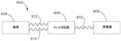
発電機(602)は、超音波駆動成分及びRF駆動成分を含む単一の出力波形(610)(「駆動信号」とも呼ばれる)を生成し、発するように構成されている。フィルタ回路(606)は、単一の出力波形(610)を受信し、その超音波駆動成分及びRF駆動成分を分離するように構成されている。より具体的には、フィルタ回路(606)は、単一の出力波形(610)を超音波駆動波形(612)及び別個のRF駆動波形(614)に変換する。超音波駆動波形(612)は、外科用器具(602)の超音波トランスデューサを駆動して、組織を切断及び/又は封止するための超音波エネルギーを生成するように構成されており、RF駆動波形(614)は、組織を封止するための電気外科用双極RFエネルギーで外科用器具(602)の双極RF電極に通電するように構成されている。 The generator (602) is configured to generate and emit a single output waveform (610) (also referred to as a "drive signal") that includes an ultrasonic drive component and an RF drive component. The filter circuit (606) is configured to receive a single output waveform (610) and separate its ultrasonic and RF drive components. More specifically, the filter circuit (606) converts the single output waveform (610) into an ultrasonic drive waveform (612) and a separate RF drive waveform (614). The ultrasonic drive waveform (612) is configured to drive an ultrasonic transducer of the surgical instrument (602) to generate ultrasonic energy for cutting and/or sealing tissue and RF drive. Waveform (614) is configured to energize the bipolar RF electrodes of surgical instrument (602) with electrosurgical bipolar RF energy to seal the tissue.
ほんの一例として、フィルタ回路(606)は、その開示が参照により本明細書に組み込まれる、2017年3月30日に公開された米国特許出願公開第2017/0086910号、名称「Techniques for Circuit Topologies for Combined Generator」、その開示が参照により本明細書に組み込まれる、2017年3月30日に公開された米国特許出願公開第2017/0086908号、名称「Circuit Topologies for Combined Generator」、その開示が参照により本明細書に組み込まれる、2017年3月30日に公開された米国特許出願公開第2017/0086911号、名称「Circuits for Supplying Isolated Direct Current(DC)Voltage to Surgical Instruments」、その開示が参照により本明細書に組み込まれる、2017年3月30日に公開された米国特許出願公開第2017/0086909号、名称「Frequency Agile Generator for a Surgical Instrument」、及び/又はその開示が参照により本明細書に組み込まれる、2017年3月30日に公開された米国特許出願公開第2017/0086876号、名称「Method and Apparatus for Selecting Operations of a Surgical Instrument Based on User Intention」の教示に従って構築され、機能してよい。 By way of example only, the filter circuit (606) may include a filter circuit (606), U.S. Patent Application Publication No. 2017/0086910, published March 30, 2017, the disclosure of which is hereby incorporated by reference. United States Patent Application Publication No. 2017/0086908, entitled "Circuit Topologies for Combined Generator," the disclosure of which is incorporated herein by reference, the disclosure of which is incorporated by reference. U.S. Patent Application Publication No. 2017/0086911, published Mar. 30, 2017, entitled "Circuits for Supplied Isolated Direct Current (DC) Voltage to Surgical Instruments," incorporated herein by reference. U.S. Patent Application Publication No. 2017/0086909, published on March 30, 2017, entitled "Frequency Agile Generator for a Surgical Instrument," and/or its disclosures, incorporated herein by reference. US Pat. Appl. Pub. No. 2017/0086876, published March 30, 2017, entitled "Method and Apparatus for Selecting Operations of a Surgical Instrument Based on User Intent".
超音波駆動波形(612)及びRF駆動波形(614)は、超音波トランスデューサ及び外科用器具(604)の双極RF電極に同時に送達されてよく、それにより、器具(604)は、超音波エネルギー及び電気外科用双極RFエネルギーを同時に印加して組織を治療できる。超音波エネルギー及びRFエネルギーは選択的に印加されてよく、印加されたエネルギーの様々なパラメータは、例えば、エネルギー制御ボタン(28、30)など発電機(602)及び/又は外科用器具(604)上に設けられるユーザ入力機構を使用して選択的に調整されてよい。様々な実施例では、外科用システム(600)は、外科用システム(600)の制御回路に予めプログラムされたエネルギー印加アルゴリズムに基づいて、所定のレベル及び/又はパターンの超音波エネルギー及び/又はRFエネルギーを送達するように構成されてよい。かかるアルゴリズムとしては、参照により本明細書に組み込まれる、2014年3月4日に発行された米国特許第8,663,220号、名称「Ultrasonic Surgical Instruments」、参照により本明細書に組み込まれる、2017年1月5日に公開された米国特許出願公開第2017/0000541号、名称「Surgical Instrument with User Adaptable Techniques」、及び/又は参照により本明細書に組み込まれる、任意の他の特許若しくは特許出願に開示されている例示的なアルゴリズムのうちの任意の1つ以上が挙げられ得る。 The ultrasonic drive waveform (612) and the RF drive waveform (614) may be simultaneously delivered to the ultrasonic transducer and the bipolar RF electrodes of the surgical instrument (604), which causes the instrument (604) to transmit ultrasonic energy and Electrosurgical bipolar RF energy can be applied simultaneously to treat tissue. Ultrasound energy and RF energy may be selectively applied, and the various parameters of the applied energy may be, for example, a generator (602) such as an energy control button (28, 30) and/or a surgical instrument (604). It may be selectively adjusted using a user input mechanism provided above. In various embodiments, the surgical system (600) may have a predetermined level and/or pattern of ultrasonic energy and/or RF based on an energy application algorithm pre-programmed in the control circuitry of the surgical system (600). It may be configured to deliver energy. Such algorithms include, for example, US Pat. No. 8,663,220 issued Mar. 4, 2014, entitled “Ultrasonic Surgical Instruments”, incorporated herein by reference, and incorporated herein by reference. U.S. Patent Application Publication No. 2017/0000541, published on January 5, 2017, entitled "Surgical Instrument with User Adaptable Technologies," and/or any other patent or patent application incorporated herein by reference. Any one or more of the exemplary algorithms disclosed in.
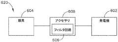
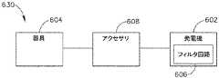
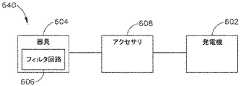
フィルタ回路(606)は、外科用システム(600)内の様々な好適な位置に配置されてよい。図10は、外科用システム(620)の形態の外科用システム(600)の第1の例示的な変形例を示し、この変形例では、フィルタ回路(606)は、電力ケーブル又はケーブルアダプタ(例えば、電力ケーブル(406、506)又はケーブルアダプタ(408、508)など)の形態であり得るアクセサリデバイス(608)に組み込まれている。図11は、外科用システム(630)の形態の外科用システム(600)の第2の例示的な変形例を示し、フィルタ回路(606)は、発電機(602)に組み込まれている。図12は、外科用システム(630)の形態の外科用システム(600)の第3の例示的な変形例を示し、フィルタ回路(606)は、外科用器具(604)に組み込まれている。 The filter circuit (606) may be located at various suitable locations within the surgical system (600). FIG. 10 illustrates a first exemplary variation of a surgical system (600) in the form of a surgical system (620) in which a filter circuit (606) includes a power cable or cable adapter (eg, , Accessory cables (608), which may be in the form of power cables (406, 506) or cable adapters (408, 508), etc. FIG. 11 shows a second exemplary variation of surgical system (600) in the form of surgical system (630), where filter circuit (606) is incorporated into generator (602). FIG. 12 shows a third exemplary variation of surgical system (600) in the form of surgical system (630) wherein filter circuit (606) is incorporated into surgical instrument (604).
図13は、図12の外科用システム(630)の一般的な構成による、内部の様々な任意の位置に配置されたフィルタ回路(606)を有する外科用器具(404)を示す。図示するように、単なる例として、フィルタ回路(606)は、ハンドルアセンブリ(420)の近位部分内において、内装された超音波トランスデューサ(410)の近位側に配置されてよい。あるいは、フィルタ回路(606)は、ハンドルアセンブリ(420)のピストルグリップ(422)の下部内にある。 FIG. 13 illustrates a surgical instrument (404) having a filter circuit (606) located at various arbitrary locations therein, in accordance with the general configuration of the surgical system (630) of FIG. As shown, by way of example only, the filter circuit (606) may be located within the proximal portion of the handle assembly (420), proximal of the embedded ultrasonic transducer (410). Alternatively, the filter circuit (606) is in the lower portion of the pistol grip (422) of the handle assembly (420).
図14は、図12の外科用システム(630)の一般的な構成による、内部に配置されたフィルタ回路(606)を有する外科用器具(504)を示す。図示するように、単なる例として、フィルタ回路(606)は、外付けの超音波トランスデューサ(510)に組み込まれてよい。 14 illustrates a surgical instrument (504) having a filter circuit (606) disposed therein according to the general configuration of the surgical system (630) of FIG. As shown, by way of example only, the filter circuit (606) may be incorporated into an external ultrasonic transducer (510).
C.EEPROM及びASICの例示的な配置
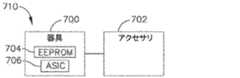
本明細書に開示される例示的な外科用システムのいずれかに、少なくとも1つの電気的消去可能プログラマブルROM(「EEPROM」)、及び特定用途向け集積回路(「ASIC」)を備えることが望ましい場合がある。例えば、1つ以上のEEPROMは、特定の製造入力及びシステム設定を記録して保持し、外科用器具及び/又は電力ケーブルなど外科用システムの1つ以上の構成要素の使用状況を追跡するために提供されてよい。かかるEEPROMは、外科用システムの発電機と連通して配置され得、したがって、発電機はEEPROMによって収集されたデータを読み取り得る。ASICは、エネルギー制御ボタン(28、30)など外科用器具の構成要素によって発せられるアナログ信号を受信するために設けられてよい。アナログ信号の受信に応答して、ASICは、外科用器具の状態を示す、対応するデジタル信号を生成して発し、このデジタル信号は発電機によって受信される。デジタル信号の受信に応答して、発電機は、発電機によって発せられる出力波形の超音波駆動成分及び/又はRF駆動成分の調整など、1つ以上の所定の動作を実行してよい。以下に記載する例示的な外科用システムの各EEPROM及びASICは、例えば、1本以上のワイヤを備え得る専用通信回線を介して、外科用システムの発電機と通信し得ることが理解されよう。C. Exemplary Placement of EEPROM and ASIC At least one electrically erasable programmable ROM (“EEPROM”) and an application specific integrated circuit (“ASIC”) for any of the exemplary surgical systems disclosed herein. )) may be desirable. For example, one or more EEPROMs may be used to record and maintain certain manufacturing inputs and system settings and to track usage of one or more components of the surgical system, such as surgical instruments and/or power cables. May be provided. Such an EEPROM may be placed in communication with the generator of the surgical system and thus the generator may read the data collected by the EEPROM. The ASIC may be provided to receive analog signals emitted by components of the surgical instrument, such as energy control buttons (28, 30). In response to receiving the analog signal, the ASIC generates and emits a corresponding digital signal indicative of the condition of the surgical instrument, which digital signal is received by the generator. In response to receiving the digital signal, the generator may perform one or more predetermined actions, such as adjusting an ultrasonically driven component and/or an RF driven component of the output waveform emitted by the generator. It will be appreciated that each EEPROM and ASIC of the exemplary surgical system described below may communicate with the generator of the surgical system via, for example, a dedicated communication line that may comprise one or more wires.
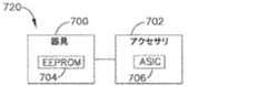
図15〜20は、外科用器具(700)と、電力ケーブル又はケーブルアダプタの形態であり得るアクセサリデバイス(702)と、を有する例示的な外科用システムを示す。各外科用システムは、1つ以上のEEPROM(704)及びASIC(706)を含む。以下に記載するように、EEPROM(704)及びASIC(706)は、外科用器具(700)及びアクセサリデバイス(702)に対して様々な構成で配置されてよい。以下に記載する全ての例示的な外科用システムは、上記の外科用システムのいずれかを表し得ることが理解されよう。例えば、外科用器具(700)は、外科用器具(14、404、504、604)のいずれかを表してよく、アクセサリデバイス(702)は、電力ケーブル(406、506)及びケーブルアダプタ(408、508)のうちのいずれか1つ以上を表してよい。更に、以下に記載する全ての例示的な外科用システムは、上記の発電機(12、402、502、602)のいずれかに類似の発電機を組み込んでよい。 15-20 illustrate an exemplary surgical system having a surgical instrument (700) and an accessory device (702) that may be in the form of a power cable or cable adapter. Each surgical system includes one or more EEPROM (704) and ASIC (706). As described below, EEPROM (704) and ASIC (706) may be arranged in various configurations for surgical instrument (700) and accessory device (702). It will be appreciated that all the exemplary surgical systems described below may represent any of the surgical systems described above. For example, the surgical instrument (700) may represent any of the surgical instruments (14, 404, 504, 604) and the accessory device (702) may be a power cable (406, 506) and a cable adapter (408, Any one or more of 508) may be represented. Further, all exemplary surgical systems described below may incorporate a generator similar to any of the generators (12, 402, 502, 602) described above.
図15は、EEPROM(704)及びASIC(706)の両方が外科用器具(700)に組み込まれている、第1の例示的な外科用システム(710)を示す。 FIG. 15 shows a first exemplary surgical system (710) in which both an EEPROM (704) and an ASIC (706) are incorporated into a surgical instrument (700).
図16は、EEPROM(704)が外科用器具(700)に組み込まれ、ASIASIC(706)は、システム(720)の電力ケーブル又はケーブルアダプタなどアクセサリデバイス(702)に組み込まれている、第2の例示的な外科用システム(720)を示す。 FIG. 16 shows a second EEPROM (704) is incorporated into the surgical instrument (700) and an ASASIC (706) is incorporated into an accessory device (702) such as the power cable or cable adapter of the system (720). 1 illustrates an exemplary surgical system (720).
図17は、第1のEEPROM(704)及びASIC(706)が外科用器具(700)に組み込まれ、第2のEEPROM(704)が、電力ケーブル又はシステム(730)のケーブルアダプタなどアクセサリデバイス(702)に組み込まれている、第3の例示的な外科用システム(730)を示す。かかる場合、電力ケーブルアダプタ及びケーブルアダプタは、互いから解放可能に分離できてよい、又は分離できなくてよい。 FIG. 17 shows that a first EEPROM (704) and ASIC (706) are incorporated into the surgical instrument (700) and a second EEPROM (704) is an accessory device (such as a power cable or cable adapter for the system (730) ( 702) shows a third exemplary surgical system (730) incorporated. In such cases, the power cable adapter and the cable adapter may or may not be releasably separable from each other.
図18は、第1のEEPROM(704)が外科用器具(700)に組み込まれ、第2のEEPROM(704)及びASIC(706)がアクセサリデバイス(702)に組み込まれている、第4の例示的な外科用システム(740)を示す。例えば、一例では、第2のEEPROM(704)及びASIC(706)の両方が、システム(740)の電力ケーブル又はケーブルアダプタに組み込まれてよい。別の例では、第2のEEPROM(704)は、電力ケーブル又はケーブルアダプタのうちの一方に組み込まれてよく、ASIC(706)は、電力ケーブル又はケーブルアダプタのうちの他方に組み込まれてよい。かかる実施例では、電力ケーブルアダプタ及びケーブルアダプタは、互いから解放可能に分離できてよい、又は分離できなくてよい。 FIG. 18 shows a fourth example where a first EEPROM (704) is incorporated into the surgical instrument (700) and a second EEPROM (704) and ASIC (706) is incorporated into the accessory device (702). 10 shows an exemplary surgical system (740). For example, in one example, both the second EEPROM (704) and ASIC (706) may be incorporated into the power cable or cable adapter of the system (740). In another example, the second EEPROM (704) may be incorporated into one of the power cables or cable adapters and the ASIC (706) may be incorporated into the other of the power cables or cable adapters. In such an embodiment, the power cable adapter and the cable adapter may or may not be releasably separable from each other.
図19は、第1のEEPROM(704)及びASIC(706)が外科用器具(700)に組み込まれ、第2及び第3のEEPROM(704)がアクセサリデバイス(702)に組み込まれている、第5の例示的な外科用システム(750)を示す。例えば、システム(750)は、互いに解放可能に分離できる電力ケーブル及びケーブルアダプタを含んでよく、第2のEEPROM(704)は電力ケーブルに組み込まれ、第3のEEPROM(704)はケーブルアダプタに組み込まれている。 FIG. 19 shows a first EEPROM (704) and ASIC (706) incorporated into the surgical instrument (700) and a second and third EEPROM (704) incorporated into the accessory device (702). 5 illustrates five exemplary surgical systems (750). For example, system (750) may include a power cable and a cable adapter that are releasably separable from each other, with a second EEPROM (704) incorporated into the power cable and a third EEPROM (704) incorporated into the cable adapter. Has been.
図20は、第1のEEPROM(704)が外科用器具(700)に組み込まれ、第2及び第3のEEPROM(704)並びにASIC(706)がアクセサリデバイス(702)に組み込まれている、第6の例示的な外科用システム(760)を示す。例えば、システム(760)は、互いに解放可能に分離できる電力ケーブル及びケーブルアダプタを含んでよく、第2のEEPROM(704)は電力ケーブルに組み込まれ、第3のEEPROM(704)及びASIC(706)はケーブルアダプタに組み込まれている。別の例では、第2のEEPROM(704)及びASIC(706)は、電力ケーブルに組み込まれてよく、第3のEEPROM(704)は、ケーブルアダプタに組み込まれてよい。 FIG. 20 shows a first EEPROM (704) incorporated into a surgical instrument (700) and a second and third EEPROM (704) and an ASIC (706) incorporated into an accessory device (702). 6 illustrates six exemplary surgical systems (760). For example, the system (760) may include a power cable and a cable adapter that are releasably separable from each other, the second EEPROM (704) incorporated into the power cable, the third EEPROM (704) and the ASIC (706). Is built into the cable adapter. In another example, the second EEPROM (704) and ASIC (706) may be incorporated into the power cable and the third EEPROM (704) may be incorporated into the cable adapter.
上記の各外科用システム(710、720、730、740、750、760)は、外科用器具(700)に組み込まれているEEPROM(704)を含む。この器具EEPROM(704)は、他のタスクの中でも、特に外科用器具(700)の使用状況を追跡するように機能し、それによって、ユーザは、外科用器具(700)が使用されている外科手術の回数を追跡可能になる。外科用システム(730、740、750、760)は、システム(730、740、750、760)の電力ケーブル及び/又はケーブルアダプタ(すなわち、「アクセサリデバイス」)に組み込まれている、少なくとも1つの追加のEEPROM(704)をそれぞれ含む。これらの追加のアクセサリEEPROM(704)のそれぞれは、アクセサリEEPROMと一体化されている、対応する電力ケーブル又はケーブルアダプタの使用状況を追跡し、それにより、ユーザは、外科用器具(700)の使用とは別に、電力ケーブル及び/又はケーブルアダプタの使用状況を監視可能になる。 Each of the surgical systems (710, 720, 730, 740, 750, 760) described above includes an EEPROM (704) incorporated into the surgical instrument (700). This instrument EEPROM (704) serves, among other tasks, to track the usage of the surgical instrument (700), thereby allowing the user to perform surgical procedures in which the surgical instrument (700) is being used. It becomes possible to track the number of operations. At least one additional surgical system (730, 740, 750, 760) incorporated into the power cable and/or cable adapter (ie, "accessory device") of the system (730, 740, 750, 760) Of the respective EEPROMs (704). Each of these additional accessory EEPROMs (704) tracks the usage of the corresponding power cable or cable adapter that is integrated with the accessory EEPROM so that the user can use the surgical instrument (700). Apart from this, the usage status of the power cable and/or the cable adapter can be monitored.
例示的な外科用システム(710、720、730、740、750、760)のうちの1つ以上では、アクセサリデバイス(702)は、例えば複数の外科用器具(700)を使用して、複数の外科手術に再利用可能であるように、外科用器具(700)と解放可能に結合されてよい。解放可能な結合は、外科用システム(400)に関連して上記したもののいずれかの形態であってよい。あるいは、アクセサリデバイス(702)は、例えば、単一の患者に対して実行される1つ以上の外科手術後に再利用不能であり、使用済みの外科用器具(700)と共に廃棄されるように、外科用器具(700)と解放不能に結合されてよい。例えば、アクセサリデバイス(702)は、ASIC(706)が外科用システム(720、740、760)などアクセサリデバイス(702)に組み込まれている外科用システムにおいて、外科用器具(700)と解放不能に結合されてよい。 In one or more of the exemplary surgical systems (710, 720, 730, 740, 750, 760), the accessory device (702) is provided with a plurality of surgical instruments (700), for example. It may be releasably associated with the surgical instrument (700) so that it can be reused for surgery. The releasable bond may be in any form of those described above in connection with surgical system (400). Alternatively, the accessory device (702) is non-reusable, for example after one or more surgical procedures performed on a single patient, and is discarded with the used surgical instrument (700), It may be non-releasably associated with the surgical instrument (700). For example, the accessory device (702) is non-releasable with the surgical instrument (700) in a surgical system where the ASIC (706) is incorporated into the accessory device (702), such as the surgical system (720, 740, 760). May be combined.
図21〜23は、ハンドルアセンブリ(800)と、ハンドルアセンブリ(800)に解放可能に結合され、かつそれによって支持される、外付けの超音波トランスデューサ(802)と、を有する、例示的な外科用器具を概略的に示す。その点において、以下に記載する外科用器具は、図8及び14に示す外科用器具(504)の様々な例示的な構成を表し得る。各外科用器具は、少なくとも1つのEEPROM(804)と、ASIC(806)と、を含み、これらは、上記のEEPROM(704)及びASIC(706)に機能面で類似であってよい。外付けの超音波トランスデューサ(802)の一部の変形例は、再利用可能な構成要素として構成されてよい。加えて、又は代替的に、ハンドルアセンブリ(800)の一部の変形形態は、再利用可能な構成要素として構成されてよい。 21-23 illustrate an exemplary surgical procedure having a handle assembly (800) and an external ultrasonic transducer (802) releasably coupled to and supported by the handle assembly (800). 1 schematically shows a tool. In that regard, the surgical instruments described below may represent various exemplary configurations of the surgical instrument (504) shown in FIGS. 8 and 14. Each surgical instrument includes at least one EEPROM (804) and ASIC (806), which may be functionally similar to the EEPROM (704) and ASIC (706) described above. Some variations of the external ultrasonic transducer (802) may be configured as reusable components. Additionally or alternatively, some variations of handle assembly (800) may be configured as reusable components.
図21は、第1のEEPROM(804)及びASIC(806)がハンドルアセンブリ(800)に組み込まれ、第2のEEPROM(804)が外付けの超音波トランスデューサ(802)に組み込まれている、第1の例示的な外科用器具(810)を示す。第1のEEPROM(804)は、ハンドルアセンブリ(800)の使用状況を追跡するように構成され、第2のEEPROM(806)は、ハンドルアセンブリ(800)の使用状況とは別に、外部トランスデューサ(802)の使用状況を追跡するように構成されている。 FIG. 21 shows a first EEPROM (804) and ASIC (806) incorporated into the handle assembly (800) and a second EEPROM (804) incorporated into an external ultrasonic transducer (802). 1 illustrates one exemplary surgical instrument (810). A first EEPROM (804) is configured to track the usage of the handle assembly (800) and a second EEPROM (806) is separate from the usage of the handle assembly (800) and an external transducer (802). ) Is configured to track usage.
図22は、第1のEEPROM(804)がハンドルアセンブリ(800)に組み込まれ、第2のEEPROM(804)及びASIC(806)が外付けの超音波トランスデューサ(802)に組み込まれている、第2の例示的な外科用器具(820)を示す。第1及び第2のEEPROM(804)は、上記の外科用器具(810)の第1及び第2のEEPROMと同様に機能するように構成されている。 FIG. 22 shows a first EEPROM (804) incorporated into the handle assembly (800) and a second EEPROM (804) and ASIC (806) incorporated into an external ultrasonic transducer (802). 2 illustrates two exemplary surgical instruments (820). The first and second EEPROMs (804) are configured to function similarly to the first and second EEPROMs of the surgical instrument (810) described above.
図23は、単一のEEPROM(804)及びASIC(806)を有する第3の例示的な外科用器具(830)を示し、これらは、両方ともハンドルアセンブリ(800)に組み込まれている。本実施例では、EEPROM(804)は、ハンドルアセンブリ(800)の使用状況を追跡するように構成されており、これは、例えば、トランスデューサ(802)が異なるハンドルアセンブリ(800)と組み合わせて以前に使用されている場合、外付けの超音波トランスデューサ(802)の使用状況とは異なる場合がある。 FIG. 23 shows a third exemplary surgical instrument (830) having a single EEPROM (804) and ASIC (806), both of which are incorporated into the handle assembly (800). In this example, the EEPROM (804) is configured to track the usage of the handle assembly (800), which has been previously described, for example, in combination with the handle assembly (800) where the transducer (802) is different. If used, it may differ from the usage of the external ultrasonic transducer (802).
III.例示的な組み合わせ
以下の実施例は、本明細書の教示を組み合わせるか又は適用することができる、種々の非網羅的な方法に関する。以下の実施例は、本出願における又は本出願の後の出願におけるどの時点でも提示され得る、いずれの請求項の適用範囲をも限定することを目的としたものではない、と理解すべきである。一切の棄権を意図するものではない。以下の実施例は、単なる例示の目的で与えられるものに過ぎない。本明細書の種々の教示は、他の多くの方法で構成及び適用が可能であると考えられている。また、いくつかの変形形態では、以下の実施例において言及される特定の特徴を省略してよいことも、考えられる。したがって、本発明者又は本発明者の利益の継承者により、後日、そうである旨が明示的に示されない限り、以下に言及される態様又は特徴のいずれも重要なものとして見なされるべきではない。以下に言及される特徴以外の更なる特徴を含む請求項が本出願において、又は本出願に関連する後の出願において示される場合、それらの更なる特徴は、特許性に関連するいかなる理由によっても追加されたものとして仮定されるべきではない。III. Illustrative Combinations The following examples relate to various non-exhaustive methods in which the teachings herein can be combined or applied. It should be understood that the following examples are not intended to limit the scope of any claims that may be presented at any point in this application or any subsequent application of this application. .. It is not intended to abstain. The following examples are provided for illustrative purposes only. It is contemplated that the various teachings herein may be constructed and applied in many other ways. It is also contemplated that in some variations certain features referred to in the examples below may be omitted. Accordingly, none of the aspects or features referred to below should be considered significant unless, by such inventor or a successor of the inventor's interests, be explicitly indicated at a later date. .. Where claims including additional features other than those mentioned below are set forth in this application or in subsequent applications related to this application, those additional features may be reserved for any reason related to patentability. It should not be assumed as added.
外科用システムであって、(a)外科用器具であって、(i)本体と、(ii)本体によって支持される超音波トランスデューサと、(iii)本体から遠位側に延在するシャフトと、(iv)シャフトの遠位端に配置されたエンドエフェクタであって、エンドエフェクタは、超音波エネルギーを用いて組織を治療するように動作可能である、エンドエフェクタと、を備える、外科用器具と、(b)外科用器具を発電機と動作可能に結合するように構成されているアクセサリデバイスであって、発電機は、外科用器具に電力を供給し、超音波エネルギーを提供するように動作可能である、アクセサリデバイスと、(c)外科用器具の本体内に設けられた第1の電気的消去可能プログラマブルROM(EEPROM)であって、第1のEEPROMは、外科用器具の使用状況を追跡するように動作可能である、第1のEEPROMと、(d)(i)アクセサリデバイスに組み込まれているアクセサリEEPROMであって、アクセサリEEPROMは、アクセサリデバイスの使用状況を追跡するように動作可能である、アクセサリEEPROM、(ii)超音波トランスデューサに組み込まれているトランスデューサEEPROMであって、トランスデューサEEPROMは、超音波トランスデューサの使用状況を追跡するように動作可能である、トランスデューサEEPROM、又は(iii)アクセサリデバイスに組み込まれているアクセサリ特定用途向け集積回路(ASIC)であって、アクセサリASICは、外科用器具の状態に関して発電機と通信するように動作可能である、アクセサリASICのうちの少なくとも1つと、を備える、外科用システム。 A surgical system comprising: (a) a surgical instrument comprising: (i) a body; (ii) an ultrasonic transducer carried by the body; and (iii) a shaft extending distally from the body. , (Iv) an end effector disposed at the distal end of the shaft, the end effector being operable to treat tissue with ultrasonic energy. (B) an accessory device configured to operably couple the surgical instrument with a generator, the electrical generator for powering the surgical instrument and providing ultrasonic energy. An operable accessory device and (c) a first electrically erasable programmable ROM (EEPROM) provided within the body of the surgical instrument, the first EEPROM being the usage status of the surgical instrument. A first EEPROM operable to track an accessory device, and (d)(i) an accessory EEPROM incorporated into the accessory device, the accessory EEPROM operable to track usage of the accessory device. An accessory EEPROM, (ii) a transducer EEPROM embedded in the ultrasonic transducer, the transducer EEPROM being operable to track the usage of the ultrasonic transducer, or (iii) ) An accessory application specific integrated circuit (ASIC) embedded in an accessory device, wherein the accessory ASIC is operable to communicate with a generator regarding the status of a surgical instrument. A surgical system comprising:
(a)外科用器具に結合するように構成されている電力ケーブルと、(b)電力ケーブルを発電機と結合するように構成されているケーブルアダプタと、を更に備え、アクセサリデバイスが、電力ケーブル又はケーブルアダプタのうちの1つを備える、実施例1の外科用システム。 The accessory device further comprises: (a) a power cable configured to couple to a surgical instrument; and (b) a cable adapter configured to couple the power cable to a generator. Or the surgical system of Example 1, comprising one of the cable adapters.
アクセサリEEPROMを更に備え、アクセサリEEPROMは電力ケーブルに組み込まれている、実施例2に記載の外科用システム。 The surgical system according to Example 2, further comprising an accessory EEPROM, the accessory EEPROM being incorporated into the power cable.
アクセサリEEPROMを更に備え、アクセサリEEPROMはケーブルアダプタに組み込まれている、実施例2に記載の外科用システム。 The surgical system according to Example 2, further comprising an accessory EEPROM, the accessory EEPROM being incorporated into the cable adapter.
外科用器具に組み込まれている器具ASICを更に備え、器具ASICは、外科用器具の状態に関して発電機と通信するように動作可能である、実施例1〜4のいずれかに記載の外科用システム。 The surgical system of any of Examples 1-4, further comprising an instrument ASIC incorporated into the surgical instrument, the instrument ASIC operable to communicate with a generator regarding the status of the surgical instrument. ..
アクセサリASICを更に備え、アクセサリASICは、電力ケーブル又はケーブルアダプタのうちの1つに組み込まれている、実施例2〜5のいずれかに記載の外科用システム。 The surgical system of any of Examples 2-5, further comprising an accessory ASIC, the accessory ASIC being incorporated into one of the power cable or cable adapter.
アクセサリASICはケーブルアダプタに組み込まれている、実施例6に記載の外科用システム。 The surgical system of Example 6, wherein the accessory ASIC is incorporated into the cable adapter.
外科用器具に組み込まれている器具ASICを更に備え、器具ASICは、外科用器具の状態に関して発電機と通信するように動作可能である、実施例1〜7のいずれかに記載の外科用システム。 The surgical system of any of Examples 1-7, further comprising an instrument ASIC incorporated into the surgical instrument, the instrument ASIC operable to communicate with a generator regarding the status of the surgical instrument. ..
ケーブルアダプタは、電力ケーブルに解放不能に結合されている、実施例2〜8のいずれかに記載の外科用システム。 The surgical system according to any of Examples 2-8, wherein the cable adapter is non-releasably coupled to the power cable.
ケーブルアダプタは、電力ケーブルに解放可能に結合されている、実施例2〜8のいずれかに記載の外科用システム。 The surgical system according to any of Examples 2-8, wherein the cable adapter is releasably coupled to the power cable.
超音波トランスデューサが本体の外部に配置されている、実施例1〜10のいずれかに記載の外科用システム。 The surgical system of any of Examples 1-10, wherein the ultrasonic transducer is located external to the body.
本体又は超音波トランスデューサのうちの1つの内部に設けられる器具ASICを更に備える、実施例11に記載の外科用システム。 The surgical system according to example 11, further comprising an instrument ASIC provided within the body or one of the ultrasonic transducers.
トランスデューサEEPROMを更に備え、超音波トランスデューサが本体の外部に配置されている、実施例1〜12のいずれかに記載の外科用システム。 13. The surgical system of any of Examples 1-12, further comprising a transducer EEPROM, wherein the ultrasonic transducer is located external to the body.
外科用システムが、外科用器具の本体内に設けられた第1のEEPROMと、電力ケーブルに組み込まれている第2のEEPROMと、ケーブルアダプタに組み込まれている第3のEEPROMと、を備え、第1のEEPROMは、外科用器具の使用状況を追跡するように動作可能であり、第2のEEPROMは、外科用器具の使用状況から独立して、電力ケーブルの使用状況を追跡するように動作可能であり、第3のEEPROMは、外科用器具の使用状況及び電力ケーブルの使用状況から独立して、ケーブルアダプタの使用状況を追跡するように動作可能であり、電力ケーブルは、外科用器具及びケーブルアダプタと解放可能に結合するように構成されており、ケーブルアダプタは、発電機と解放可能に結合するように構成されている、実施例2〜13のいずれかに記載の外科用システム。 A surgical system comprises a first EEPROM provided in a body of a surgical instrument, a second EEPROM incorporated in a power cable, and a third EEPROM incorporated in a cable adapter, The first EEPROM is operable to track usage of the surgical instrument and the second EEPROM is operable to track usage of the power cable, independent of usage of the surgical instrument. And a third EEPROM is operable to track the usage of the cable adapter, independent of the surgical instrument usage and the power cable usage, the power cable The surgical system of any of Examples 2-13, configured to releasably couple with a cable adapter, the cable adapter configured to releasably couple with a generator.
エンドエフェクタが、(A)超音波ブレードであって、超音波トランスデューサが、超音波エネルギーを用いて超音波ブレードを駆動するように動作可能である、超音波ブレードと、(B)超音波ブレードとの間に組織を挟持するために超音波ブレードに対して移動可能なクランプアームと、(C)クランプアームによって提供される第1のRF電極と、(D)超音波ブレードによって提供される第2のRF電極であって、第1及び第2のRF電極は、発電機によって提供される双極RFエネルギーを用いて組織を封止するように動作可能である、第2のRF電極と、を備える、実施例1〜14のいずれかに記載の外科用システム。 An ultrasonic blade, wherein the end effector is an (A) ultrasonic blade and the ultrasonic transducer is operable to drive the ultrasonic blade with ultrasonic energy; and (B) an ultrasonic blade. A clamp arm movable relative to the ultrasonic blade to clamp tissue between the two; (C) a first RF electrode provided by the clamp arm; and (D) a second provided by the ultrasonic blade. RF electrodes, the first and second RF electrodes being operable to seal tissue with bipolar RF energy provided by a generator. The surgical system of any of Examples 1-14.
外科用システムであって、(a)外科用器具であって、(i)長手方向に延在するシャフトと、(ii)シャフトの遠位端に配置されたエンドエフェクタであって、エンドエフェクタは、超音波エネルギー又はRFエネルギーのうちの少なくとも1つを用いて組織を治療するように動作可能である、エンドエフェクタと、を備える、外科用器具と、(b)外科用器具を発電機と動作可能に結合するように構成されているアクセサリデバイスであって、発電機は外科用器具に電力を供給し、超音波エネルギー又はRFエネルギーのうちの少なくとも1つを提供するように動作可能である、アクセサリデバイスと、(c)外科用器具に組み込まれている第1の電気的消去可能プログラマブルROM(EEPROM)であって、第1のEEPROMは、外科用器具の使用状況を追跡するように動作可能である、第1のEEPROMと、(d)電力ケーブル又はケーブルアダプタのうちの1つに組み込まれている第2のEEPROMであって、第2のEEPROMは、電力ケーブル又はケーブルアダプタのうちの1つの使用状況を追跡するように動作可能である、第2のEEPROMと、を備える、外科用システム。 A surgical system comprising: (a) a surgical instrument, (i) a longitudinally extending shaft, and (ii) an end effector disposed at a distal end of the shaft, the end effector comprising: A surgical instrument operable to treat tissue with at least one of ultrasonic energy or RF energy; and (b) operating the surgical instrument with a generator. An accessory device configured to operably couple, wherein a generator is operable to power the surgical instrument and provide at least one of ultrasonic energy or RF energy. An accessory device and (c) a first electrically erasable programmable ROM (EEPROM) incorporated in the surgical instrument, the first EEPROM operable to track usage of the surgical instrument. And (d) a second EEPROM incorporated in one of the power cables or cable adapters, the second EEPROM being one of the power cables or cable adapters. A second EEPROM operable to track one usage condition.
第2のEEPROMは、ケーブルアダプタと一体化されており、第2のEEPROMは、ケーブルアダプタの使用状況を追跡するように動作可能である、実施例16に記載の外科用システム。 The surgical system according to example 16, wherein the second EEPROM is integrated with the cable adapter and the second EEPROM is operable to track usage of the cable adapter.
ケーブルアダプタは、電力ケーブルに解放可能に結合されており、外科用システムは、電力ケーブルと一体化されている第3のEEPROMを更に備え、第3のEEPROMは、電力ケーブルの使用状況を追跡するように動作可能である、実施例17に記載の外科用システム。 The cable adapter is releasably coupled to the power cable and the surgical system further comprises a third EEPROM integrated with the power cable, the third EEPROM tracking usage of the power cable. The surgical system of Example 17, which is operable to:
外科用器具であって、(a)本体と、(b)本体の外部に配置された超音波トランスデューサと、(c)本体から遠位側に延在するシャフトと、(d)シャフトの遠位端に配置されたエンドエフェクタであって、エンドエフェクタは、超音波エネルギーを用いて組織を治療するように動作可能である、エンドエフェクタと、(e)本体と一体化されている電気的消去可能プログラマブルROM(EEPROM)であって、第1のEEPROMは、本体の使用状況を追跡するように動作可能である、EEPROMと、(f)本体又は超音波トランスデューサのうちの1つと一体化されている特定用途向け集積回路(ASIC)であって、ASICは、外科用器具の状態に関して発電機と通信するように動作可能である、ASICと、を備える、外科用器具。 A surgical instrument comprising: (a) a body, (b) an ultrasonic transducer located outside the body, (c) a shaft extending distally from the body, and (d) a distal end of the shaft. An end-located end effector operable to treat tissue with ultrasonic energy, the end effector being electrically erasable integrated with the body (e). A programmable ROM (EEPROM), wherein the first EEPROM is operable to track usage of the body and is integrated with the EEPROM and (f) the body or one of the ultrasonic transducers. An application specific integrated circuit (ASIC), wherein the ASIC is operable to communicate with a generator regarding the status of the surgical instrument.
超音波トランスデューサと一体化されている第2のEEPROMを更に備え、第2のEEPROMは、本体の使用状況から独立して、超音波トランスデューサの使用状況を追跡するように動作可能である、実施例19に記載の外科用器具。 Embodiments further comprising a second EEPROM integrated with the ultrasonic transducer, the second EEPROM being operable to track the usage of the ultrasonic transducer independent of the usage of the body. 19. The surgical instrument according to 19.
IV.その他
本明細書に記載の教示、表現要素、実施形態、実施例などのうちのいずれか1つ又は2つ以上を、本明細書に記載の他の教示、表現要素、実施形態、実施例などのうちのいずれか1つ又は2つ以上と組み合わせることができる点が理解されるべきである。したがって、上記の教示、表現、実施形態、実施例などは、互いに対して独立して考慮されるべきではない。本明細書の教示を鑑みると、本明細書の教示を組み合わせることができる種々の好適な方法が、当業者には直ちに明らかとなろう。このような改変及び変形形態は、「特許請求の範囲」内に含まれるものとする。IV. Others One or more of the teachings, expression elements, embodiments, examples, etc. described in this specification may be replaced with other teachings, expression elements, embodiments, examples, etc., described in this specification. It should be understood that any one or more of these can be combined. Therefore, the above teachings, expressions, embodiments, examples, etc. should not be considered independently of each other. Various suitable ways in which the teachings herein may be combined will be readily apparent to those of ordinary skill in the art in view of the teachings herein. Such modifications and variations are intended to be included within the scope of the "claims".
更に、本明細書に記載する教示、表現、実施形態、実施例などのうちの任意の1つ以上を、本件と同日に出願された米国特許出願[代理人整理番号END8245USNP]、名称「Combination Ultrasonic and Electrosurgical Instrument Having Electrical Circuits With Shared Return Path」、本件と同日に出願された米国特許出願[代理人整理番号END8245USNP1]、名称「Combination Ultrasonic and Electrosurgical Instrument Having Slip Ring Electrical Contact Assembly」、本件と同日に出願された米国特許出願[代理人整理番号END8245USNP2]、名称「Combination Ultrasonic and Electrosurgical Instrument Having Electrically Insulating Features」、本件と同日に出願された米国特許出願[代理人整理番号END8245USNP3]、名称「Combination Ultrasonic and Electrosurgical Instrument Having Curved Ultrasonic Blade」、本件と同日に出願された米国特許出願[代理人整理番号END8245USNP4]、名称「Combination Ultrasonic and Electrosurgical Instrument Having Clamp Arm Electrode」、本件と同日に出願された米国特許出願[代理人整理番号END8245USNP5]、名称「Combination Ultrasonic and Electrosurgical Instrument Having Ultrasonic Waveguide With Distal Overmold Member」、及び/又は本件と同日に出願された米国特許出願[代理人整理番号END8245USNP6]、名称「Combination Ultrasonic and Electrosurgical System Having Generator Filter Circuitry」に記載される教示、表現、実施形態、実施例などのうちの任意の1つ以上と組み合わせてよい。これらの出願のそれぞれの開示は、参照により本明細書に組み込まれる。 In addition, any one or more of the teachings, expressions, embodiments, examples, etc. described herein may be incorporated by reference in the US patent application filed on the same date as the present application [Attorney Docket END8245USNP], entitled "Combination Ultrasonic." and Electrosurgical Instrument Having Electrical Circuits with Shared Return Path ", the present and the United States patent application which was filed on the same day [Attorney Docket No. END8245USNP1], entitled" Combination Ultrasonic and Electrosurgical Instrument Having Slip Ring Electrical Contact Assembly ", filed this matter and on the same day U.S. patent application filed [Attorney Docket No. END8245USNP2], entitled "Combination Ultrasonic and Electrosurgical Instrumental Haven Electrical Couplings Insulating Features", and U.S. patent application filed at the same date as this patent application No. "Instrument Having Curved Ultrasonic Blade", US patent application filed on the same date as the present application [Attorney Docket END8245USNP4], and "Combination Ultrasonic and Electrological Application Arme patent application filed on the same day as "U.S.A. Person reference number END8245USNP5], the name "Combination Ultrasonic and Electrosurgical Instrument Having Ultrasonic Waveguide with Uthus United Co., Ltd.", and the application number and/or the same number as the patent application number "US8" and the application filed in the same number as the patent application number and/or the patent application filed in the same application as the patent application and/or the present application. may be combined with any one or more of the teachings, expressions, embodiments, examples, etc., described in "And Electrosurgical System Having Generator Filter Circuit". The disclosure of each of these applications is incorporated herein by reference.
更に、本明細書に記載する教示、表現、実施形態、実施例などのうちの任意の1つ以上を、本件と同日に出願された米国特許出願[代理人整理番号END8146USNP]、名称「Combination Ultrasonic and Electrosurgical Instrument with Clamp Arm Position Input and Method for Identifying Tissue State」、本件と同日に出願された米国特許出願[代理人整理番号END8146USNP1]、名称「Combination Ultrasonic and Electrosurgical Instrument with Adjustable Energy Modalities and Method for Sealing Tissue and Inhibiting Tissue Resection」、本件と同日に出願された米国特許出願[代理人整理番号END8146USNP2]、名称「Combination Ultrasonic and Electrosurgical Instrument with Adjustable Clamp Force and Related Methods」、本件と同日に出願された米国特許出願[代理人整理番号END8146USNP3]、名称「Combination Ultrasonic and Electrosurgical Instrument with Adjustable Energy Modalities and Method for Limiting Blade Temperature」、本件と同日に出願された米国特許出願[代理人整理番号END8146USNP4]、名称「Combination Ultrasonic and Electrosurgical Instrument and Method for Sealing Tissue with Various Termination Parameters」、及び/又は本件と同日に出願された米国特許出願[代理人整理番号END8146USNP5]、名称「Combination Ultrasonic and Electrosurgical Instrument and Method for Sealing Tissue in Successive Phases」に記載される教示、表現、実施形態、実施例などのうちの任意の1つ以上と組み合わせてよい。これらの出願のそれぞれの開示は、参照により本明細書に組み込まれる。 In addition, any one or more of the teachings, expressions, embodiments, examples, etc. described herein may be incorporated by reference into the US patent application filed on the same date as the present application [Attorney Docket END8146USNP], entitled "Combination Ultrasonic." and Electrosurgical Instrument with Clamp Arm Position Input and Method for Identifying Tissue State ", the present and the United States patent application filed on the same day [Attorney Docket No. END8146USNP1], entitled" Combination Ultrasonic and Electrosurgical Instrument with Adjustable Energy Modalities and Method for Sealing Tissue and Inhibiting Tissue Resurrection," U.S. patent application filed on the same date as the present application [Attorney Docket No. END8146USNP2], entitled "Combination Ultrasonic and Electrosurgical Instrument with Adhesive Rs. application patent, on the same date." [Attorney Docket No. END8146USNP3], entitled "Combination Ultrasonic and Electrosurgical Instrument with Adjustable Energy Modalities and Method for Limiting Blade Temperature", the present and the United States patent application filed on the same day [Attorney Docket No. END8146USNP4], entitled "Combination Ultrasonic and Electrosurgical Instrument and Method for Sealing Tissue with Various Termination Parameters, and/or a U.S. patent application filed on the same date as the present application [Attorney docket number END8146USNP5], entitled "Co Any combination of one or more of the teachings, expressions, embodiments, examples, etc. described in "Mbination Ultrasonic and Electrosurgical Instrument and Method for Sealing Tissue in Successive Phases". The disclosure of each of these applications is incorporated herein by reference.
本明細書に参考として組み込まれると言及されたいかなる特許、公報、又は他の開示内容も、全体的に又は部分的に、組み込まれた内容が現行の定義、見解、又は本明細書に記載される他の開示内容とあくまで矛盾しない範囲でのみ本明細書に組み込まれる、と理解されなければならない。それ自体、また必要な範囲で、本明細書に明瞭に記載される開示内容は、参照により本明細書に組み込まれるあらゆる矛盾する記載に優先するものとする。参照により本明細書に組み込まれるものとするが、既存の定義、記述、又は本明細書に記載される他の開示文献と矛盾する任意の文献、又はそれらの部分は、組み込まれる文献と既存の開示内容との間に矛盾が生じない範囲でしか組み込まれないものとする。 Any patents, publications, or other disclosures referred to herein as incorporated by reference are wholly or partly incorporated in their present definition, view, or specification. It should be understood that the present disclosure is incorporated into the present specification only to the extent not inconsistent with other disclosure contents. As such, and to the extent necessary, the disclosure expressly set forth herein supersedes any contradictory statements incorporated herein by reference. Any document, or part thereof, which is hereby incorporated by reference but is inconsistent with an existing definition, description, or other disclosed document mentioned herein, shall be incorporated by reference with the incorporated document. It should be incorporated only to the extent that it does not conflict with the disclosed content.
上記のデバイスのバージョンは、医療専門家により行われる従来の医療処置及び手術における用途のみではなく、ロボット支援された医療処置及び手術における用途をも有することができる。あくまで一例として、本明細書の様々な教示は、ロボット外科用システム、例えばIntuitive Surgical,Inc.(Sunnyvale,California)によるDAVINCI(商標)システムなどに容易に組み込むことができる。同様に、当業者であれば、本明細書における様々な教示を、その開示が参照により本明細書に組み込まれる、1998年8月11日に発行された、米国特許第5,792,135号、名称「Articulated Surgical Instrument For Performing Minimally Invasive Surgery With Enhanced Dexterity and Sensitivity」、その開示が参照により本明細書に組み込まれる、1998年10月6日に発行された、米国特許第5,817,084号、名称「Remote Center Positioning Device with Flexible Drive」、その開示が参照により本明細書に組み込まれる、1999年3月2日に交付された、米国特許第5,878,193号、名称「Automated Endoscope System for Optimal Positioning」、その開示が参照により本明細書に組み込まれる、2001年5月15日に交付された、米国特許第6,231,565号、名称「Robotic Arm DLUS for Performing Surgical Tasks」、その開示が参照により本明細書に組み込まれる、2004年8月31日に発行された米国特許第6,783,524号、名称「Robotic Surgical Tool with Ultrasound Cauterizing and Cutting Instrument」、その開示が参照により本明細書に組み込まれる、2002年4月2日に交付された、米国特許第6,364,888号、名称「Alignment of Master and Slave in a Minimally Invasive Surgical Apparatus」、その開示が参照により本明細書に組み込まれる、2009年4月28日に交付された、米国特許第7,524,320号、名称「Mechanical Actuator Interface System for Robotic Surgical Tools」、その開示が参照により本明細書に組み込まれる、2010年4月6日に交付された、米国特許第7,691,098号、名称「Platform Link Wrist Mechanism」、その開示が参照により本明細書に組み込まれる、2010年10月5日に発行された、米国特許第7,806,891号、名称「Repositioning and Reorientation of Master/Slave Relationship in Minimally Invasive Telesurgery」、その開示が参照により本明細書に組み込まれる、2014年9月30日に発行された、米国特許第8,844,789号、名称「Automated End Effector Component Reloading System for Use with a Robotic System」、その開示が参照により本明細書に組み込まれる、2014年9月2日に発行された、米国特許第8,820,605号、名称「Robotically−Controlled Surgical Instruments」、その開示が参照により本明細書に組み込まれる、2013年12月31日に発行された、米国特許第8,616,431号、名称「Shiftable Drive Interface for Robotically−Controlled Surgical Tool」、その開示が参照により本明細書に組み込まれる、2013年11月5日に公開された、米国特許第8,573,461号、名称「Surgical Stapling Instruments with Cam−Driven Staple Deployment Arrangements」、その開示が参照により本明細書に組み込まれる、2013年12月10日に発行された、米国特許第8,602,288号、名称「Robotically−Controlled Motorized Surgical End Effector System with Rotary Actuated Closure Systems Having Variable Actuation Speeds」、その開示が参照により本明細書に組み込まれる、2016年4月5日に発行された、米国特許第9,301,759号、名称「Robotically−Controlled Surgical Instrument with Selectively Articulatable End Effector」、その開示が参照により本明細書に組み込まれる、2014年7月22日に発行された、米国特許第8,783,541号、名称「Robotically−Controlled Surgical End Effector System」、2013年7月9日に発行された、米国特許第8,479,969号、名称「Drive Interface for Operably Coupling a Manipulatable Surgical Tool to a Robot」、その開示が参照により本明細書に組み込まれる、2014年8月12日に発行された米国特許出願第8,800,838号、名称「Robotically−Controlled Cable−Based Surgical End Effectors」、及び/又はその開示が参照により本明細書に組み込まれる、2013年11月5日に発行された、米国特許第8,573,465号、名称「Robotictically Controlled Surgical End Effector System with Rotary Actuated Closure Systems」のうちの任意の様々な教示と容易に組み合わせ得ることを認識するであろう。 The device versions described above may have applications not only in conventional medical procedures and surgery performed by medical professionals, but also in robot-assisted medical procedures and surgery. By way of example only, various teachings herein may be directed to robotic surgical systems, such as Intuitive Surgical, Inc. (Sunnyvale, California) and the like can be easily incorporated into a DAVINCI™ system. Similarly, one of ordinary skill in the art will appreciate that the various teachings herein are incorporated into US Pat. No. 5,792,135, issued Aug. 11, 1998, the disclosure of which is incorporated herein by reference. , "Articulated Surgical Instrument For Performing Minimally Invasive Surgery With Enhanced Dexterity Dexterity and Sensitivity", the disclosures of which are incorporated by reference in the present specification on the 8th and the 8th patents on the 8th and the 19th patents on the 8th and the 19th patents, the disclosure is incorporated in the present specification by the specification on the 8th, the 10th, the patent is incorporated by reference, the specification is incorporated in the present specification on the 8th, the tenth, the specification is incorporated into the present specification by the specification. , Remote Center Positioning Device with Flexible Drive, US Pat. No. 5,878,193, issued March 2, 1999, entitled “Automated Endoscope Scope,” the disclosure of which is incorporated herein by reference. for Optimal Positioning", US Pat. No. 6,231,565, entitled "Robotic Arm DLUS for Performing Surgical Tasks," issued May 15, 2001, the disclosure of which is incorporated herein by reference. US Patent No. 6,783,524 issued August 31, 2004, entitled "Robotic Surgical Tool with Ultrasound Catering and Cutting Instrument," the disclosure of which is hereby incorporated by reference. U.S. Patent No. 6,364,888, entitled "Alignment of Master and Slave in a Minimally Inactive Surgical Apparatus," issued April 2, 2002, the disclosure of which is incorporated herein by reference. No. 7,524,320, entitled "Mechanical Actuator Interface System for Robotic Surgical Tools," issued April 28, 2009, the disclosure of which is incorporated herein by reference. Issued on April 6, 2012 US Pat. No. 7,691,098, entitled “Platform Link Wrist Mechanism,” US Pat. No. 7,806, issued October 5, 2010, the disclosure of which is incorporated herein by reference. ,891, entitled "Repositioning and Reorientation of Master/Slave Relations in Minimally Invertive Telecommunication," the disclosure of which is incorporated herein by reference, September 8, 2014, 4, U.S. Pat. No. 789, entitled "Automated End Effector Component Reloading System for Use with a Robotic System," the disclosure of which is incorporated herein by reference, U.S. Patent No. 8,820,60. No. 8,616,431 issued Dec. 31, 2013, entitled “Shiftable Drive Interface for”, the disclosure of which is hereby incorporated by reference, for example, “Robotically-Controlled Surgical Instruments”. "Robotically-Controlled Surgical Tool," U.S. Pat. No. 8,573,461, entitled "Surgical Stapling Instruments with Driven-SrivingSrivingSpublished November 5, 2013, the disclosure of which is incorporated herein by reference. "Deployment Arrangements", U.S. Patent No. 8,602,288, entitled "Robologically Controlled Surgical End effector System", the disclosure of which is incorporated herein by reference. Closure Systems Having Variable Acting Speeds", US Pat. No. 9, issued April 5, 2016, the disclosure of which is incorporated herein by reference. , 301,759, entitled "Robotically-Controlled Surgical Instrument with Selective Artificial End Effector," the disclosure of which is incorporated herein by reference, July 22, 2014, 3, U.S. Pat. No. 541, "Robotically-Controlled Surgical End Effector System," issued on July 9, 2013, U.S. Pat. No. 8,479,969, "Driving Interface for Opto-Absorbing Couplings". , U.S. Patent Application No. 8,800,838, issued Aug. 12, 2014, the disclosure of which is incorporated herein by reference, entitled "Robotically-Controlled Cable-Based Surgical End Effects," and/or Of US Pat. No. 8,573,465, entitled “Robotically Controlled Surgical End Effector System With Rotated Actuated Closed Closures,” issued Nov. 5, 2013, the disclosure of which is incorporated herein by reference. It will be appreciated that any of the various teachings can be readily combined.
上述のデバイスのバージョンは、1回の使用後に処分するように設計することができ、又はそれらは、複数回使用するように設計することができる。変形形態は、いずれか又は両方の場合においても、少なくとも1回の使用後に再利用のために再調整され得る。再調整は、デバイスの分解工程、それに続く特定の部品の洗浄又は交換工程、及びその後の再組み立て工程の、任意の組み合わせを含み得る。特に、デバイスのいくつかの変形形態は分解することができ、また、デバイスの任意の数の特定の部分若しくは部品を、任意の組み合わせで選択的に交換又は取り外してもよい。特定の部品の洗浄及び/又は交換後、デバイスのいくつかの変形形態を、再調整用の施設において、又は処置の直前に使用者によってのいずれかで、その後の使用のために再組み立てすることができる。当業者であれば、デバイスの再調整において、分解、洗浄/交換、及び再組み立てのための様々な技術を利用することができることを理解するであろう。こうした技術の使用、及び結果として得られる再調整された装置は、全て本出願の範囲内にある。 The versions of the devices described above can be designed for single-use disposal, or they can be designed for multiple-use. The variant may be readjusted for reuse after at least one use in either or both cases. Reconditioning may include any combination of device disassembly steps, followed by cleaning or replacement of certain parts, and subsequent reassembly steps. In particular, some variations of the device may be disassembled and any number of the particular parts or parts of the device may be selectively replaced or removed in any combination. After cleaning and/or replacement of certain parts, reassembling some variations of the device for subsequent use, either in a facility for reconditioning or by the user just prior to the procedure. You can Those of ordinary skill in the art will appreciate that reconditioning of a device can utilize a variety of techniques for disassembly, cleaning/replacement, and reassembly. Use of such techniques, and the resulting reconditioned device, are all within the scope of the present application.
単に一例として、本明細書に記載される変形形態は、処置の前及び/又は後に滅菌されてもよい。1つの滅菌技術では、デバイスをプラスチック製又はTYVEK製のバックなど、閉鎖及び封止された容器に入れる。次いで、容器及びデバイスを、γ線、X線、又は高エネルギー電子線などの、容器を透過し得る放射線場に置いてもよい。放射線は、デバイス上及び容器内の細菌を死滅させ得る。次に、滅菌されたデバイスを、後の使用のために、滅菌容器内に保管してもよい。β線若しくはγ線、エチレンオキシド、又は水蒸気が挙げられるがこれらに限定されない、当該技術分野で既知の任意の他の技術を用いて、デバイスを滅菌してもよい。 Merely by way of example, the variants described herein may be sterilized before and/or after treatment. In one sterilization technique, the device is placed in a closed and sealed container, such as a plastic or TYVEK bag. The container and device may then be placed in a radiation field that can penetrate the container, such as gamma rays, X-rays, or high energy electron beams. Radiation can kill bacteria on the device and in the container. The sterilized device may then be stored in the sterile container for later use. The device may be sterilized using any other technique known in the art, including but not limited to beta or gamma radiation, ethylene oxide, or water vapor.
以上、本発明の種々の実施形態を図示及び説明したが、本発明の範囲から逸脱することなく、当業者による適切な改変により、本明細書に記載される方法及びシステムの更なる適合化を実現することができる。このような可能な改変のうちのいくつかについて述べたが、他の改変も当業者には明らかとなるであろう。例えば、上記の実施例、実施形態、形状、材料、寸法、比率、工程などは例示的なものであって、必須のものではない。したがって、本発明の範囲は、以下の特許請求の範囲の観点から考慮されるべきものであり、本明細書及び図面において図示され、説明された構造及び動作の細部に限定されないものとして、理解されたい。 While various embodiments of the present invention have been illustrated and described, it will be appreciated by those skilled in the art that appropriate adaptations of the methods and systems described herein may be made without departing from the scope of the invention. Can be realized. Although some of these possible modifications have been mentioned, other modifications will be apparent to those skilled in the art. For example, the above examples, embodiments, shapes, materials, dimensions, ratios, steps, etc. are illustrative and not essential. Accordingly, the scope of the present invention should be considered in terms of the following claims, and is not to be understood as being limited to the details of construction and operation illustrated and described herein. I want to.
〔実施の態様〕
(1) 外科用システムであって、
(a)外科用器具であって、
(i)本体と、
(ii)前記本体によって支持される超音波トランスデューサと、
(iii)前記本体から遠位側に延在するシャフトと、
(iv)前記シャフトの遠位端に配置されたエンドエフェクタであって、前記エンドエフェクタは、超音波エネルギーを用いて組織を治療するように動作可能である、エンドエフェクタと、を備える、外科用器具と、
(b)前記外科用器具を発電機と動作可能に結合するように構成されているアクセサリデバイスであって、前記発電機は、前記外科用器具に電力を供給し、超音波エネルギーを提供するように動作可能である、アクセサリデバイスと、
(c)前記外科用器具の前記本体内に設けられた第1の電気的消去可能プログラマブルROM(EEPROM)であって、前記第1のEEPROMは、前記外科用器具の使用状況を追跡するように動作可能である、第1のEEPROMと、
(d)以下:
(i)前記アクセサリデバイスに組み込まれているアクセサリEEPROMであって、前記アクセサリEEPROMは、前記アクセサリデバイスの使用状況を追跡するように動作可能である、アクセサリEEPROM、
(ii)前記超音波トランスデューサに組み込まれているトランスデューサEEPROMであって、前記トランスデューサEEPROMは、前記超音波トランスデューサの使用状況を追跡するように動作可能である、トランスデューサEEPROM、又は
(iii)前記アクセサリデバイスに組み込まれているアクセサリ特定用途向け集積回路(ASIC)であって、前記アクセサリASICは、前記外科用器具の状態に関して前記発電機と通信するように動作可能である、アクセサリASIC、
のうちの少なくとも1つと、を備える、外科用システム。
(2) (a)前記外科用器具に結合するように構成されている電力ケーブルと、
(b)前記電力ケーブルを前記発電機と結合するように構成されているケーブルアダプタと、を更に備え、
前記アクセサリデバイスは、前記電力ケーブル又は前記ケーブルアダプタのうちの1つを備える、実施態様1に記載の外科用システム。
(3) 前記アクセサリEEPROMを更に備え、前記アクセサリEEPROMは前記電力ケーブルに組み込まれている、実施態様2に記載の外科用システム。
(4) 前記アクセサリEEPROMを更に備え、前記アクセサリEEPROMは前記ケーブルアダプタに組み込まれている、実施態様2に記載の外科用器具。
(5) 前記外科用器具に組み込まれている器具ASICを更に備え、前記器具ASICは、前記外科用器具の状態に関して前記発電機と通信するように動作可能である、実施態様4に記載の外科用器具。Embodiments
(1) A surgical system,
(A) A surgical instrument,
(I) the main body,
(Ii) an ultrasonic transducer supported by the main body,
(Iii) a shaft extending distally from the body,
(Iv) an end effector disposed at a distal end of the shaft, the end effector operable to treat tissue with ultrasonic energy. A fixture,
(B) an accessory device configured to operably couple the surgical instrument with a generator, the generator providing power to the surgical instrument and providing ultrasonic energy. An accessory device that is
(C) a first electrically erasable programmable ROM (EEPROM) provided within the body of the surgical instrument, the first EEPROM for tracking usage of the surgical instrument. A first EEPROM, which is operable,
(D) The following:
(I) an accessory EEPROM incorporated into the accessory device, the accessory EEPROM being operable to track usage of the accessory device;
(Ii) a transducer EEPROM embedded in the ultrasonic transducer, the transducer EEPROM being operable to track usage of the ultrasonic transducer, or (iii) the accessory device. An accessory specific application integrated circuit (ASIC) embedded in the accessory ASIC, the accessory ASIC being operable to communicate with the generator regarding the status of the surgical instrument;
At least one of: and a surgical system.
(2) (a) a power cable configured to couple to the surgical instrument;
(B) further comprising a cable adapter configured to couple the power cable with the generator,
The surgical system according to embodiment 1, wherein the accessory device comprises one of the power cable or the cable adapter.
(3) The surgical system according to Embodiment 2, further comprising the accessory EEPROM, wherein the accessory EEPROM is incorporated in the power cable.
(4) The surgical instrument according to embodiment 2, further comprising the accessory EEPROM, wherein the accessory EEPROM is incorporated in the cable adapter.
(5) A surgical instrument according to embodiment 4, further comprising an instrument ASIC incorporated into the surgical instrument, the instrument ASIC being operable to communicate with the generator regarding the status of the surgical instrument. Equipment.
(6) 前記アクセサリASICを更に備え、前記アクセサリASICは、前記電力ケーブル又は前記ケーブルアダプタのうちの1つに組み込まれている、実施態様4に記載の外科用器具。
(7) 前記アクセサリASICを更に備え、前記アクセサリASICは、前記電力ケーブル又は前記ケーブルアダプタのうちの1つに組み込まれている、実施態様2に記載の外科用システム。
(8) 前記アクセサリASICは前記ケーブルアダプタに組み込まれている、実施態様7に記載の外科用システム。
(9) 前記外科用器具に組み込まれている器具ASICを更に備え、前記器具ASICは、前記外科用器具の状態に関して前記発電機と通信するように動作可能である、実施態様2に記載の外科用システム。
(10) 前記ケーブルアダプタは、前記電力ケーブルに解放不能に結合されている、実施態様2に記載の外科用器具。(6) The surgical instrument according to embodiment 4, further comprising the accessory ASIC, wherein the accessory ASIC is incorporated in one of the power cable or the cable adapter.
(7) The surgical system according to embodiment 2, further comprising the accessory ASIC, wherein the accessory ASIC is incorporated in one of the power cable or the cable adapter.
(8) The surgical system according to embodiment 7, wherein the accessory ASIC is incorporated in the cable adapter.
(9) The surgical instrument of embodiment 2, further comprising an instrument ASIC incorporated into the surgical instrument, the instrument ASIC being operable to communicate with the generator regarding the status of the surgical instrument. System.
(10) The surgical instrument according to embodiment 2, wherein the cable adapter is non-releasably coupled to the power cable.
(11) 前記ケーブルアダプタは、前記電力ケーブルに解放可能に結合されている、実施態様2に記載の外科用器具。
(12) 前記超音波トランスデューサは前記本体の外部に配置されている、実施態様1に記載の外科用システム。
(13) 前記本体又は前記超音波トランスデューサのうちの1つに組み込まれている器具ASICを更に備える、実施態様12に記載の外科用システム。
(14) 前記トランスデューサEEPROMを更に備え、前記超音波トランスデューサは前記本体の外部に配置されている、実施態様1に記載の外科用システム。
(15) 前記エンドエフェクタは、
(A)超音波ブレードであって、前記超音波トランスデューサは、超音波エネルギーを用いて前記超音波ブレードを駆動するように動作可能である、超音波ブレードと、
(B)前記超音波ブレードとの間に組織を挟持するために前記超音波ブレードに対して移動可能なクランプアームと、
(C)前記クランプアームによって提供される第1のRF電極と、
(D)前記超音波ブレードによって提供される第2のRF電極であって、前記第1及び第2のRF電極は、前記発電機によって提供される双極RFエネルギーを用いて組織を封止するように動作可能である、第2のRF電極と、を備える、実施態様1に記載の外科用システム。(11) The surgical instrument according to embodiment 2, wherein the cable adapter is releasably coupled to the power cable.
(12) The surgical system according to Embodiment 1, wherein the ultrasonic transducer is arranged outside the main body.
(13) The surgical system according to
(14) The surgical system according to Embodiment 1, further comprising the transducer EEPROM, wherein the ultrasonic transducer is arranged outside the main body.
(15) The end effector is
(A) an ultrasonic blade, wherein the ultrasonic transducer is operable to drive the ultrasonic blade with ultrasonic energy;
(B) a clamp arm movable with respect to the ultrasonic blade to clamp tissue between the ultrasonic blade and the ultrasonic blade,
(C) a first RF electrode provided by the clamp arm,
(D) A second RF electrode provided by the ultrasonic blade, wherein the first and second RF electrodes seal tissue using bipolar RF energy provided by the generator. A second RF electrode operable with the surgical system of claim 1, and the surgical system of embodiment 1.
(16) 外科用システムであって、
(a)外科用器具であって、
(i)長手方向に延在するシャフトと、
(ii)前記シャフトの遠位端に配置されたエンドエフェクタであって、前記エンドエフェクタは、超音波エネルギー又はRFエネルギーのうちの少なくとも1つを用いて組織を治療するように動作可能である、エンドエフェクタと、を備える、外科用器具と、
(b)前記外科用器具を発電機と動作可能に結合するように構成されているアクセサリデバイスであって、前記発電機は、前記外科用器具に電力を供給し、超音波エネルギー又はRFエネルギーのうちの少なくとも1つを提供するように動作可能である、アクセサリデバイスと、
(c)前記外科用器具に組み込まれている第1の電気的消去可能プログラマブルROM(EEPROM)であって、前記第1のEEPROMは、前記外科用器具の使用状況を追跡するように動作可能である、第1のEEPROMと、
(d)前記電力ケーブル又は前記ケーブルアダプタのうちの1つに組み込まれている第2のEEPROMであって、前記第2のEEPROMは、前記電力ケーブル又は前記ケーブルアダプタのうちの前記1つの使用状況を追跡するように動作可能である、第2のEEPROMと、を備える、外科用システム。
(17) 前記第2のEEPROMは、前記ケーブルアダプタと一体化されており、前記第2のEEPROMは、前記ケーブルアダプタの使用状況を追跡するように動作可能である、実施態様16に記載の外科用システム。
(18) 前記ケーブルアダプタは、前記電力ケーブルに解放可能に結合されており、前記外科用システムは、前記電力ケーブルと一体化されている第3のEEPROMを更に備え、前記第3のEEPROMは、前記電力ケーブルの使用状況を追跡するように動作可能である、実施態様17に記載の外科用システム。
(19) 外科用器具であって、
(a)本体と、
(b)前記本体の外部に配置された超音波トランスデューサと、
(c)前記本体から遠位側に延在するシャフトと、
(d)前記シャフトの遠位端に配置されたエンドエフェクタであって、前記エンドエフェクタは、超音波エネルギーを用いて組織を治療するように動作可能である、エンドエフェクタと、
(e)前記本体と一体化されている電気的消去可能プログラマブルROM(EEPROM)であって、前記第1のEEPROMは、前記本体の使用状況を追跡するように動作可能である、EEPROMと、
(f)前記本体又は前記超音波トランスデューサのうちの1つと一体化されている特定用途向け集積回路(ASIC)であって、前記ASICは、前記外科用器具の状態に関して前記発電機と通信するように動作可能である、ASICと、を備える、外科用器具。
(20) 前記超音波トランスデューサと一体化されている第2のEEPROMを更に備え、前記第2のEEPROMは、前記本体の使用状況から独立して、前記超音波トランスデューサの使用状況を追跡するように動作可能である、実施態様19に記載の外科用器具。(16) A surgical system,
(A) A surgical instrument,
(I) a shaft extending in the longitudinal direction,
(Ii) an end effector disposed at the distal end of the shaft, the end effector operable to treat tissue with at least one of ultrasonic energy or RF energy. A surgical instrument comprising an end effector;
(B) an accessory device configured to operably couple the surgical instrument with a generator, the generator supplying electrical power to the surgical instrument to generate ultrasonic or RF energy. An accessory device operable to provide at least one of the:
(C) a first electrically erasable programmable ROM (EEPROM) incorporated into the surgical instrument, the first EEPROM operable to track usage of the surgical instrument. There is a first EEPROM,
(D) A second EEPROM incorporated in one of the power cable or the cable adapter, wherein the second EEPROM is the usage status of the one of the power cable or the cable adapter. A second EEPROM operable to track the surgical system.
(17) The surgical apparatus according to
(18) The cable adapter is releasably coupled to the power cable, and the surgical system further comprises a third EEPROM integrated with the power cable, the third EEPROM comprising: 18. The surgical system according to embodiment 17, operable to track usage of the power cable.
(19) A surgical instrument,
(A) Main body,
(B) an ultrasonic transducer arranged outside the main body,
(C) a shaft extending distally from the body,
(D) an end effector located at the distal end of the shaft, the end effector operable to treat tissue with ultrasonic energy;
(E) An electrically erasable programmable ROM (EEPROM) integrated with the body, wherein the first EEPROM is operable to track usage of the body;
(F) an application specific integrated circuit (ASIC) integrated with the body or one of the ultrasonic transducers, wherein the ASIC communicates with the generator regarding the status of the surgical instrument. An ASIC operable with a surgical instrument.
(20) A second EEPROM integrated with the ultrasonic transducer is further provided, and the second EEPROM tracks the usage state of the ultrasonic transducer independently of the usage state of the main body. 20. The surgical instrument of embodiment 19, which is operable.
Claims (20)
Translated fromJapanese(a)外科用器具であって、
(i)本体と、
(ii)前記本体によって支持される超音波トランスデューサと、
(iii)前記本体から遠位側に延在するシャフトと、
(iv)前記シャフトの遠位端に配置されたエンドエフェクタであって、前記エンドエフェクタは、超音波エネルギーを用いて組織を治療するように動作可能である、エンドエフェクタと、を備える、外科用器具と、
(b)前記外科用器具を発電機と動作可能に結合するように構成されているアクセサリデバイスであって、前記発電機は、前記外科用器具に電力を供給し、超音波エネルギーを提供するように動作可能である、アクセサリデバイスと、
(c)前記外科用器具の前記本体内に設けられた第1の電気的消去可能プログラマブルROM(EEPROM)であって、前記第1のEEPROMは、前記外科用器具の使用状況を追跡するように動作可能である、第1のEEPROMと、
(d)以下:
(i)前記アクセサリデバイスに組み込まれているアクセサリEEPROMであって、前記アクセサリEEPROMは、前記アクセサリデバイスの使用状況を追跡するように動作可能である、アクセサリEEPROM、
(ii)前記超音波トランスデューサに組み込まれているトランスデューサEEPROMであって、前記トランスデューサEEPROMは、前記超音波トランスデューサの使用状況を追跡するように動作可能である、トランスデューサEEPROM、又は
(iii)前記アクセサリデバイスに組み込まれているアクセサリ特定用途向け集積回路(ASIC)であって、前記アクセサリASICは、前記外科用器具の状態に関して前記発電機と通信するように動作可能である、アクセサリASIC、
のうちの少なくとも1つと、を備える、外科用システム。A surgical system,
(A) A surgical instrument,
(I) the main body,
(Ii) an ultrasonic transducer supported by the main body,
(Iii) a shaft extending distally from the body,
(Iv) an end effector disposed at a distal end of the shaft, the end effector operable to treat tissue with ultrasonic energy. A fixture,
(B) an accessory device configured to operably couple the surgical instrument with a generator, the generator providing power to the surgical instrument and providing ultrasonic energy. An accessory device that is
(C) a first electrically erasable programmable ROM (EEPROM) provided within the body of the surgical instrument, the first EEPROM for tracking usage of the surgical instrument. A first EEPROM, which is operable,
(D) The following:
(I) an accessory EEPROM incorporated into the accessory device, the accessory EEPROM being operable to track usage of the accessory device;
(Ii) a transducer EEPROM embedded in the ultrasonic transducer, the transducer EEPROM being operable to track usage of the ultrasonic transducer, or (iii) the accessory device. An accessory specific application integrated circuit (ASIC) embedded in the accessory ASIC, the accessory ASIC being operable to communicate with the generator regarding the status of the surgical instrument;
At least one of: and a surgical system.
(b)前記電力ケーブルを前記発電機と結合するように構成されているケーブルアダプタと、を更に備え、
前記アクセサリデバイスは、前記電力ケーブル又は前記ケーブルアダプタのうちの1つを備える、請求項1に記載の外科用システム。(A) a power cable configured to couple to the surgical instrument;
(B) further comprising a cable adapter configured to couple the power cable to the generator,
The surgical system according to claim 1, wherein the accessory device comprises one of the power cable or the cable adapter.
(A)超音波ブレードであって、前記超音波トランスデューサは、超音波エネルギーを用いて前記超音波ブレードを駆動するように動作可能である、超音波ブレードと、
(B)前記超音波ブレードとの間に組織を挟持するために前記超音波ブレードに対して移動可能なクランプアームと、
(C)前記クランプアームによって提供される第1のRF電極と、
(D)前記超音波ブレードによって提供される第2のRF電極であって、前記第1及び第2のRF電極は、前記発電機によって提供される双極RFエネルギーを用いて組織を封止するように動作可能である、第2のRF電極と、を備える、請求項1に記載の外科用システム。The end effector is
(A) an ultrasonic blade, wherein the ultrasonic transducer is operable to drive the ultrasonic blade with ultrasonic energy;
(B) a clamp arm movable with respect to the ultrasonic blade for sandwiching tissue between the ultrasonic blade and the ultrasonic blade,
(C) a first RF electrode provided by the clamp arm,
(D) A second RF electrode provided by the ultrasonic blade, wherein the first and second RF electrodes seal tissue using bipolar RF energy provided by the generator. And a second RF electrode operable with the surgical system.
(a)外科用器具であって、
(i)長手方向に延在するシャフトと、
(ii)前記シャフトの遠位端に配置されたエンドエフェクタであって、前記エンドエフェクタは、超音波エネルギー又はRFエネルギーのうちの少なくとも1つを用いて組織を治療するように動作可能である、エンドエフェクタと、を備える、外科用器具と、
(b)前記外科用器具を発電機と動作可能に結合するように構成されているアクセサリデバイスであって、前記発電機は、前記外科用器具に電力を供給し、超音波エネルギー又はRFエネルギーのうちの少なくとも1つを提供するように動作可能である、アクセサリデバイスと、
(c)前記外科用器具に組み込まれている第1の電気的消去可能プログラマブルROM(EEPROM)であって、前記第1のEEPROMは、前記外科用器具の使用状況を追跡するように動作可能である、第1のEEPROMと、
(d)前記電力ケーブル又は前記ケーブルアダプタのうちの1つに組み込まれている第2のEEPROMであって、前記第2のEEPROMは、前記電力ケーブル又は前記ケーブルアダプタのうちの前記1つの使用状況を追跡するように動作可能である、第2のEEPROMと、を備える、外科用システム。A surgical system,
(A) A surgical instrument,
(I) a shaft extending in the longitudinal direction,
(Ii) an end effector located at the distal end of the shaft, the end effector operable to treat tissue with at least one of ultrasonic energy or RF energy. A surgical instrument comprising an end effector;
(B) an accessory device configured to operably couple the surgical instrument with a generator, the generator supplying electrical power to the surgical instrument to generate ultrasonic or RF energy. An accessory device operable to provide at least one of the:
(C) a first electrically erasable programmable ROM (EEPROM) incorporated into the surgical instrument, the first EEPROM operable to track usage of the surgical instrument. There is a first EEPROM,
(D) A second EEPROM incorporated in one of the power cable or the cable adapter, wherein the second EEPROM is the usage status of the one of the power cable or the cable adapter. A second EEPROM operable to track the surgical system.
(a)本体と、
(b)前記本体の外部に配置された超音波トランスデューサと、
(c)前記本体から遠位側に延在するシャフトと、
(d)前記シャフトの遠位端に配置されたエンドエフェクタであって、前記エンドエフェクタは、超音波エネルギーを用いて組織を治療するように動作可能である、エンドエフェクタと、
(e)前記本体と一体化されている電気的消去可能プログラマブルROM(EEPROM)であって、前記第1のEEPROMは、前記本体の使用状況を追跡するように動作可能である、EEPROMと、
(f)前記本体又は前記超音波トランスデューサのうちの1つと一体化されている特定用途向け集積回路(ASIC)であって、前記ASICは、前記外科用器具の状態に関して前記発電機と通信するように動作可能である、ASICと、を備える、外科用器具。A surgical instrument,
(A) Main body,
(B) an ultrasonic transducer arranged outside the main body,
(C) a shaft extending distally from the body,
(D) an end effector located at the distal end of the shaft, the end effector operable to treat tissue with ultrasonic energy;
(E) An electrically erasable programmable ROM (EEPROM) integrated with the body, wherein the first EEPROM is operable to track usage of the body;
(F) an application specific integrated circuit (ASIC) integrated with the body or one of the ultrasonic transducers, wherein the ASIC communicates with the generator regarding the status of the surgical instrument. An ASIC operable with a surgical instrument.
Priority Applications (1)
| Application Number | Priority Date | Filing Date | Title |
|---|---|---|---|
| JP2023040596AJP2023063489A (en) | 2017-05-22 | 2023-03-15 | Combined ultrasound and electrosurgical system with EEPROM and ASIC components |
Applications Claiming Priority (5)
| Application Number | Priority Date | Filing Date | Title |
|---|---|---|---|
| US201762509351P | 2017-05-22 | 2017-05-22 | |
| US62/509,351 | 2017-05-22 | ||
| US15/967,764 | 2018-05-01 | ||
| US15/967,764US11129661B2 (en) | 2017-05-22 | 2018-05-01 | Combination ultrasonic and electrosurgical system having EEPROM and ASIC components |
| PCT/US2018/033619WO2018217607A1 (en) | 2017-05-22 | 2018-05-21 | Combination ultrasonic and electrosurgical system having eeprom and asic components |
Related Child Applications (1)
| Application Number | Title | Priority Date | Filing Date |
|---|---|---|---|
| JP2023040596ADivisionJP2023063489A (en) | 2017-05-22 | 2023-03-15 | Combined ultrasound and electrosurgical system with EEPROM and ASIC components |
Publications (1)
| Publication Number | Publication Date |
|---|---|
| JP2020520723Atrue JP2020520723A (en) | 2020-07-16 |
Family
ID=62620977
Family Applications (9)
| Application Number | Title | Priority Date | Filing Date |
|---|---|---|---|
| JP2019564432APendingJP2020520723A (en) | 2017-05-22 | 2018-05-21 | Combined ultrasound and electrosurgical system having EEPROM and ASIC components |
| JP2019564528AActiveJP7179775B2 (en) | 2017-05-22 | 2018-05-21 | Combined ultrasonic surgical and electrosurgical instrument with slip ring electrical contact assembly |
| JP2019564478AActiveJP7179774B2 (en) | 2017-05-22 | 2018-05-21 | Combined ultrasonic and electrosurgical instrument with curved ultrasonic blade |
| JP2019564468AActiveJP7301751B2 (en) | 2017-05-22 | 2018-05-21 | Combined ultrasonic surgical and electrosurgical instrument with electrical isolation |
| JP2019564481AActiveJP7150751B2 (en) | 2017-05-22 | 2018-05-21 | Combined ultrasonic and electrosurgical instrument with clamp arm electrodes |
| JP2019564433APendingJP2020520724A (en) | 2017-05-22 | 2018-05-21 | Combined ultrasonic and electrosurgical system with generator filter circuit |
| JP2019564536APendingJP2020520739A (en) | 2017-05-22 | 2018-05-21 | Combined ultrasonic and electrosurgical instrument having an ultrasonic waveguide with a distal overmolded member |
| JP2019564527APendingJP2020520735A (en) | 2017-05-22 | 2018-05-21 | Combined ultrasound and electrosurgical instrument with electrical circuitry with shared return path |
| JP2023040596APendingJP2023063489A (en) | 2017-05-22 | 2023-03-15 | Combined ultrasound and electrosurgical system with EEPROM and ASIC components |
Family Applications After (8)
| Application Number | Title | Priority Date | Filing Date |
|---|---|---|---|
| JP2019564528AActiveJP7179775B2 (en) | 2017-05-22 | 2018-05-21 | Combined ultrasonic surgical and electrosurgical instrument with slip ring electrical contact assembly |
| JP2019564478AActiveJP7179774B2 (en) | 2017-05-22 | 2018-05-21 | Combined ultrasonic and electrosurgical instrument with curved ultrasonic blade |
| JP2019564468AActiveJP7301751B2 (en) | 2017-05-22 | 2018-05-21 | Combined ultrasonic surgical and electrosurgical instrument with electrical isolation |
| JP2019564481AActiveJP7150751B2 (en) | 2017-05-22 | 2018-05-21 | Combined ultrasonic and electrosurgical instrument with clamp arm electrodes |
| JP2019564433APendingJP2020520724A (en) | 2017-05-22 | 2018-05-21 | Combined ultrasonic and electrosurgical system with generator filter circuit |
| JP2019564536APendingJP2020520739A (en) | 2017-05-22 | 2018-05-21 | Combined ultrasonic and electrosurgical instrument having an ultrasonic waveguide with a distal overmolded member |
| JP2019564527APendingJP2020520735A (en) | 2017-05-22 | 2018-05-21 | Combined ultrasound and electrosurgical instrument with electrical circuitry with shared return path |
| JP2023040596APendingJP2023063489A (en) | 2017-05-22 | 2023-03-15 | Combined ultrasound and electrosurgical system with EEPROM and ASIC components |
Country Status (9)
| Country | Link |
|---|---|
| US (12) | US11058472B2 (en) |
| EP (10) | EP3629952B8 (en) |
| JP (9) | JP2020520723A (en) |
| CN (9) | CN110650696A (en) |
| BR (3) | BR112019024361A2 (en) |
| GB (2) | GB2608896B (en) |
| MX (8) | MX2019013908A (en) |
| PL (1) | PL3634274T3 (en) |
| WO (8) | WO2018217601A1 (en) |
Cited By (3)
| Publication number | Priority date | Publication date | Assignee | Title |
|---|---|---|---|---|
| US11957338B2 (en) | 2019-09-16 | 2024-04-16 | Cilag Gmbh International | Compressible stress and strain of non-fibrous adjuncts |
| USD1028233S1 (en) | 2018-02-21 | 2024-05-21 | Cilag Gmbh International | Three dimensional adjunct |
| USD1029255S1 (en) | 2020-09-01 | 2024-05-28 | Cilag Gmbh International | Stapling cartridge assembly with a compressible adjunct |
Families Citing this family (58)
| Publication number | Priority date | Publication date | Assignee | Title |
|---|---|---|---|---|
| US11090104B2 (en) | 2009-10-09 | 2021-08-17 | Cilag Gmbh International | Surgical generator for ultrasonic and electrosurgical devices |
| US9408622B2 (en) | 2012-06-29 | 2016-08-09 | Ethicon Endo-Surgery, Llc | Surgical instruments with articulating shafts |
| US10194973B2 (en) | 2015-09-30 | 2019-02-05 | Ethicon Llc | Generator for digitally generating electrical signal waveforms for electrosurgical and ultrasonic surgical instruments |
| US11051840B2 (en) | 2016-01-15 | 2021-07-06 | Ethicon Llc | Modular battery powered handheld surgical instrument with reusable asymmetric handle housing |
| US11129670B2 (en) | 2016-01-15 | 2021-09-28 | Cilag Gmbh International | Modular battery powered handheld surgical instrument with selective application of energy based on button displacement, intensity, or local tissue characterization |
| US11229471B2 (en) | 2016-01-15 | 2022-01-25 | Cilag Gmbh International | Modular battery powered handheld surgical instrument with selective application of energy based on tissue characterization |
| US12193698B2 (en) | 2016-01-15 | 2025-01-14 | Cilag Gmbh International | Method for self-diagnosing operation of a control switch in a surgical instrument system |
| US11266430B2 (en) | 2016-11-29 | 2022-03-08 | Cilag Gmbh International | End effector control and calibration |
| US11058472B2 (en) | 2017-05-22 | 2021-07-13 | Cilag Gmbh International | Combination ultrasonic and electrosurgical instrument having clamp arm electrode |
| US11266455B2 (en) | 2017-05-22 | 2022-03-08 | Cilag Gmbh International | Combination ultrasonic and electrosurgical instrument with a production clamp force based ultrasonic seal process and related methods |
| USD888951S1 (en)* | 2018-11-15 | 2020-06-30 | Ethicon Llc | Pair of bipolar electrosurgical jaws |
| USD966513S1 (en)* | 2019-01-25 | 2022-10-11 | Karl Storz Se & Co. Kg | Shaft attachable medical instrument |
| USD938588S1 (en)* | 2019-01-25 | 2021-12-14 | Karl Storz Se & Co. Kg | Shaft attachable medical instrument |
| US12351855B2 (en) | 2019-01-30 | 2025-07-08 | Arizona Board Of Regents On Behalf Of Arizona State University | Bioelectronic circuits, systems and methods for preparing and using them |
| AU2020253238B2 (en) | 2019-03-29 | 2025-03-06 | Gyrus Acmi, Inc. D/B/A Olympus Surgical Technologies America | Forceps motion transfer assembly |
| CN110151258B (en)* | 2019-05-01 | 2024-07-30 | 杭州康基医疗器械有限公司 | Support system for ultrasonic waveguide |
| CN110403672B (en)* | 2019-05-01 | 2024-04-19 | 杭州康基医疗器械有限公司 | Ultrasonic medical surgical instrument |
| CN110123416B (en)* | 2019-05-01 | 2024-05-07 | 杭州康基医疗器械有限公司 | Floating support structure of ultrasonic transducer |
| US12023085B2 (en) | 2019-08-29 | 2024-07-02 | Covidien Lp | Ultrasonic systems and methods with tissue resistance sensing |
| GB2594438A (en)* | 2019-12-05 | 2021-11-03 | Creo Medical Ltd | Electrosurgical instrument, generator and apparatus |
| US12343063B2 (en) | 2019-12-30 | 2025-07-01 | Cilag Gmbh International | Multi-layer clamp arm pad for enhanced versatility and performance of a surgical device |
| US12082808B2 (en) | 2019-12-30 | 2024-09-10 | Cilag Gmbh International | Surgical instrument comprising a control system responsive to software configurations |
| US12262937B2 (en) | 2019-12-30 | 2025-04-01 | Cilag Gmbh International | User interface for surgical instrument with combination energy modality end-effector |
| US12336747B2 (en) | 2019-12-30 | 2025-06-24 | Cilag Gmbh International | Method of operating a combination ultrasonic / bipolar RF surgical device with a combination energy modality end-effector |
| US11986201B2 (en) | 2019-12-30 | 2024-05-21 | Cilag Gmbh International | Method for operating a surgical instrument |
| US12114912B2 (en) | 2019-12-30 | 2024-10-15 | Cilag Gmbh International | Non-biased deflectable electrode to minimize contact between ultrasonic blade and electrode |
| US11944366B2 (en) | 2019-12-30 | 2024-04-02 | Cilag Gmbh International | Asymmetric segmented ultrasonic support pad for cooperative engagement with a movable RF electrode |
| US11937863B2 (en) | 2019-12-30 | 2024-03-26 | Cilag Gmbh International | Deflectable electrode with variable compression bias along the length of the deflectable electrode |
| US12053224B2 (en) | 2019-12-30 | 2024-08-06 | Cilag Gmbh International | Variation in electrode parameters and deflectable electrode to modify energy density and tissue interaction |
| US11786294B2 (en) | 2019-12-30 | 2023-10-17 | Cilag Gmbh International | Control program for modular combination energy device |
| US11779387B2 (en) | 2019-12-30 | 2023-10-10 | Cilag Gmbh International | Clamp arm jaw to minimize tissue sticking and improve tissue control |
| US11950797B2 (en) | 2019-12-30 | 2024-04-09 | Cilag Gmbh International | Deflectable electrode with higher distal bias relative to proximal bias |
| US11812957B2 (en) | 2019-12-30 | 2023-11-14 | Cilag Gmbh International | Surgical instrument comprising a signal interference resolution system |
| US11786291B2 (en) | 2019-12-30 | 2023-10-17 | Cilag Gmbh International | Deflectable support of RF energy electrode with respect to opposing ultrasonic blade |
| US11937866B2 (en) | 2019-12-30 | 2024-03-26 | Cilag Gmbh International | Method for an electrosurgical procedure |
| US20210196357A1 (en) | 2019-12-30 | 2021-07-01 | Ethicon Llc | Electrosurgical instrument with asynchronous energizing electrodes |
| CN113116508B (en)* | 2019-12-30 | 2023-10-20 | 北京术锐机器人股份有限公司 | Bipolar sealed surgical tool head |
| US12076006B2 (en) | 2019-12-30 | 2024-09-03 | Cilag Gmbh International | Surgical instrument comprising an orientation detection system |
| CN113116505B (en)* | 2019-12-30 | 2024-03-29 | 北京术锐机器人股份有限公司 | Monopole sealing operation tool head |
| US12023086B2 (en) | 2019-12-30 | 2024-07-02 | Cilag Gmbh International | Electrosurgical instrument for delivering blended energy modalities to tissue |
| US11523828B2 (en)* | 2020-01-28 | 2022-12-13 | Covidien Lp | Sealed reload assembly for stapling device |
| US11672590B2 (en)* | 2020-07-02 | 2023-06-13 | Covidien Lp | Slip-ring contact assembly for electrosurgical instruments |
| US20220079658A1 (en)* | 2020-09-14 | 2022-03-17 | Covidien Lp | Beveled end effector assembly |
| CN112237465A (en)* | 2020-11-04 | 2021-01-19 | 安速康医疗(苏州)有限公司 | Ultrasonic scalpel handle with ultrasonic generator function, ultrasonic scalpel system and using method of ultrasonic scalpel system |
| CN112690873B (en)* | 2020-12-25 | 2021-10-26 | 中南大学湘雅医院 | Bendable ultrasonic knife |
| WO2022185194A1 (en)* | 2021-03-02 | 2022-09-09 | Cilag Gmbh International | Adjustment feature for electrosurgical instrument |
| CN113017777B (en)* | 2021-03-08 | 2025-07-15 | 以诺康医疗科技(苏州)有限公司 | Ultrasonic surgical blade |
| CN113796933A (en)* | 2021-10-12 | 2021-12-17 | 北京派尔特医疗科技股份有限公司 | an ultrasonic knife |
| CN114366285A (en)* | 2022-01-25 | 2022-04-19 | 武汉半边天医疗技术发展有限公司 | Conductive tetrafluoro radio frequency ultrasonic knife |
| CN116549094B (en)* | 2022-01-29 | 2024-07-26 | 天津瑞奇外科器械股份有限公司 | Surgical instruments and surgical systems integrating monopolar electrosurgery and ultrasonic functions |
| CN115581506A (en)* | 2022-10-09 | 2023-01-10 | 剑虎医疗科技(苏州)有限公司 | Ultrasonic and high-frequency energy integrated dual-mode system and using method |
| CN116269728A (en)* | 2022-12-29 | 2023-06-23 | 青岛迈博思医疗科技有限公司 | Surgical instrument, waveguide rod assembly, and superelectric hybrid energy platform |
| CN115944377A (en)* | 2022-12-29 | 2023-04-11 | 青岛迈博思医疗科技有限公司 | Surgical instrument, outer sleeve, sleeve assembly and super-electricity hybrid energy platform |
| CN116421296A (en)* | 2022-12-29 | 2023-07-14 | 青岛迈博思医疗科技有限公司 | Surgical instrument suitable for super-electric hybrid energy platform |
| CN116098700B (en)* | 2023-02-01 | 2025-08-22 | 青岛迈博思医疗科技有限公司 | Surgical instruments, cannula assemblies, and super-electric hybrid energy platforms |
| US20240366255A1 (en)* | 2023-05-04 | 2024-11-07 | Cilag Gmbh International | Distal node grounding features for acoustic waveguide |
| CN116616864A (en)* | 2023-06-07 | 2023-08-22 | 青岛健新医疗科技有限公司 | Clamping assembly applicable to ultrasonic electric knife |
| IT202300012834A1 (en)* | 2023-06-21 | 2024-12-21 | Medical Microinstruments Inc | ACTIVE ELECTROSURGICAL INSTRUMENT AND PROTECTIVE CAP, PARTICULARLY FOR MEDICAL-SURGICAL TELEOPERATION, AND RELATED ROBOTIC SYSTEM |
Citations (9)
| Publication number | Priority date | Publication date | Assignee | Title |
|---|---|---|---|---|
| US5400267A (en)* | 1992-12-08 | 1995-03-21 | Hemostatix Corporation | Local in-device memory feature for electrically powered medical equipment |
| JPH11213768A (en)* | 1998-01-22 | 1999-08-06 | Nec Eng Ltd | Cable life predicting apparatus and cable used therefor |
| JP2007195634A (en)* | 2006-01-24 | 2007-08-09 | Canon Inc | Electronic device and control method thereof |
| JP2011519684A (en)* | 2008-05-05 | 2011-07-14 | マシモ コーポレイション | Pulse oximeter system with electrical disconnect circuit |
| JP2012223582A (en)* | 2011-04-15 | 2012-11-15 | Covidien Ag | Battery-powered hand-held ultrasonic surgical cautery cutting device |
| JP2013192953A (en)* | 2012-03-22 | 2013-09-30 | Ethicon Endo Surgery Inc | Method and apparatus for programming modular surgical instrument |
| JP2014236836A (en)* | 2013-06-07 | 2014-12-18 | 株式会社東芝 | Ultrasonic diagnostic equipment and attachment for use in the same |
| JP2015514474A (en)* | 2012-04-09 | 2015-05-21 | エシコン・エンド−サージェリィ・インコーポレイテッドEthicon Endo−Surgery,Inc. | Apparatus and techniques for cutting and coagulating tissue |
| US20170086876A1 (en)* | 2015-09-30 | 2017-03-30 | Ethicon Endo-Surgery, Llc | Method and apparatus for selecting operations of a surgical instrument based on user intention |
Family Cites Families (135)
| Publication number | Priority date | Publication date | Assignee | Title |
|---|---|---|---|---|
| US5295484A (en)* | 1992-05-19 | 1994-03-22 | Arizona Board Of Regents For And On Behalf Of The University Of Arizona | Apparatus and method for intra-cardiac ablation of arrhythmias |
| US5657429A (en) | 1992-08-10 | 1997-08-12 | Computer Motion, Inc. | Automated endoscope system optimal positioning |
| US5322055B1 (en) | 1993-01-27 | 1997-10-14 | Ultracision Inc | Clamp coagulator/cutting system for ultrasonic surgical instruments |
| EP0699053B1 (en) | 1993-05-14 | 1999-03-17 | Sri International | Surgical apparatus |
| US5792135A (en) | 1996-05-20 | 1998-08-11 | Intuitive Surgical, Inc. | Articulated surgical instrument for performing minimally invasive surgery with enhanced dexterity and sensitivity |
| US6364888B1 (en) | 1996-09-09 | 2002-04-02 | Intuitive Surgical, Inc. | Alignment of master and slave in a minimally invasive surgical apparatus |
| US6331181B1 (en) | 1998-12-08 | 2001-12-18 | Intuitive Surgical, Inc. | Surgical robotic tools, data architecture, and use |
| US5944737A (en)* | 1997-10-10 | 1999-08-31 | Ethicon Endo-Surgery, Inc. | Ultrasonic clamp coagulator apparatus having improved waveguide support member |
| US5989275A (en)* | 1997-02-28 | 1999-11-23 | Ethicon Endo-Surgery, Inc. | Damping ultrasonic transmission components |
| US6231565B1 (en) | 1997-06-18 | 2001-05-15 | United States Surgical Corporation | Robotic arm DLUs for performing surgical tasks |
| US5873873A (en) | 1997-10-10 | 1999-02-23 | Ethicon Endo-Surgery, Inc. | Ultrasonic clamp coagulator apparatus having improved clamp mechanism |
| US5980510A (en) | 1997-10-10 | 1999-11-09 | Ethicon Endo-Surgery, Inc. | Ultrasonic clamp coagulator apparatus having improved clamp arm pivot mount |
| CA2276316C (en) | 1998-06-29 | 2008-02-12 | Ethicon Endo-Surgery, Inc. | Method of balancing asymmetric ultrasonic surgical blades |
| US6309400B2 (en) | 1998-06-29 | 2001-10-30 | Ethicon Endo-Surgery, Inc. | Curved ultrasonic blade having a trapezoidal cross section |
| US6459926B1 (en) | 1998-11-20 | 2002-10-01 | Intuitive Surgical, Inc. | Repositioning and reorientation of master/slave relationship in minimally invasive telesurgery |
| DE19905804C1 (en)* | 1999-02-12 | 2000-02-24 | Aesculap Ag & Co Kg | Surgical instrument for removal of bone material has tool driven around rotary axis oscillating with rotary directing altering angularly |
| US6454781B1 (en)* | 1999-05-26 | 2002-09-24 | Ethicon Endo-Surgery, Inc. | Feedback control in an ultrasonic surgical instrument for improved tissue effects |
| US6432118B1 (en)* | 1999-10-05 | 2002-08-13 | Ethicon Endo-Surgery, Inc. | Multifunctional curved blade for use with an ultrasonic surgical instrument |
| US6325811B1 (en) | 1999-10-05 | 2001-12-04 | Ethicon Endo-Surgery, Inc. | Blades with functional balance asymmetries for use with ultrasonic surgical instruments |
| US6423082B1 (en) | 2000-03-31 | 2002-07-23 | Ethicon Endo-Surgery, Inc. | Ultrasonic surgical blade with improved cutting and coagulation features |
| US6500176B1 (en) | 2000-10-23 | 2002-12-31 | Csaba Truckai | Electrosurgical systems and techniques for sealing tissue |
| US6783524B2 (en) | 2001-04-19 | 2004-08-31 | Intuitive Surgical, Inc. | Robotic surgical tool with ultrasound cauterizing and cutting instrument |
| AU2002322374B2 (en) | 2001-06-29 | 2006-10-26 | Intuitive Surgical, Inc. | Platform link wrist mechanism |
| US6929644B2 (en) | 2001-10-22 | 2005-08-16 | Surgrx Inc. | Electrosurgical jaw structure for controlled energy delivery |
| US7354440B2 (en) | 2001-10-22 | 2008-04-08 | Surgrx, Inc. | Electrosurgical instrument and method of use |
| US7125409B2 (en) | 2001-10-22 | 2006-10-24 | Surgrx, Inc. | Electrosurgical working end for controlled energy delivery |
| US7311709B2 (en) | 2001-10-22 | 2007-12-25 | Surgrx, Inc. | Electrosurgical instrument and method of use |
| US7189233B2 (en) | 2001-10-22 | 2007-03-13 | Surgrx, Inc. | Electrosurgical instrument |
| AU2003205316A1 (en) | 2002-01-22 | 2003-09-02 | Sciogen Llc | Electrosurgical instrument and method of use |
| US7169146B2 (en) | 2003-02-14 | 2007-01-30 | Surgrx, Inc. | Electrosurgical probe and method of use |
| US9060770B2 (en) | 2003-05-20 | 2015-06-23 | Ethicon Endo-Surgery, Inc. | Robotically-driven surgical instrument with E-beam driver |
| US7309849B2 (en) | 2003-11-19 | 2007-12-18 | Surgrx, Inc. | Polymer compositions exhibiting a PTC property and methods of fabrication |
| US8182501B2 (en) | 2004-02-27 | 2012-05-22 | Ethicon Endo-Surgery, Inc. | Ultrasonic surgical shears and method for sealing a blood vessel using same |
| US7220951B2 (en) | 2004-04-19 | 2007-05-22 | Surgrx, Inc. | Surgical sealing surfaces and methods of use |
| US20070016236A1 (en) | 2005-07-18 | 2007-01-18 | Crescendo Technologies, Llc | Balanced ultrasonic curved blade |
| US8800838B2 (en) | 2005-08-31 | 2014-08-12 | Ethicon Endo-Surgery, Inc. | Robotically-controlled cable-based surgical end effectors |
| US7845537B2 (en) | 2006-01-31 | 2010-12-07 | Ethicon Endo-Surgery, Inc. | Surgical instrument having recording capabilities |
| US20110295295A1 (en) | 2006-01-31 | 2011-12-01 | Ethicon Endo-Surgery, Inc. | Robotically-controlled surgical instrument having recording capabilities |
| US8025630B2 (en) | 2006-02-22 | 2011-09-27 | Olympus Medical Systems Corp. | Treatment apparatus |
| US8992422B2 (en) | 2006-03-23 | 2015-03-31 | Ethicon Endo-Surgery, Inc. | Robotically-controlled endoscopic accessory channel |
| US8684253B2 (en) | 2007-01-10 | 2014-04-01 | Ethicon Endo-Surgery, Inc. | Surgical instrument with wireless communication between a control unit of a robotic system and remote sensor |
| US8057498B2 (en) | 2007-11-30 | 2011-11-15 | Ethicon Endo-Surgery, Inc. | Ultrasonic surgical instrument blades |
| US8931682B2 (en) | 2007-06-04 | 2015-01-13 | Ethicon Endo-Surgery, Inc. | Robotically-controlled shaft based rotary drive systems for surgical instruments |
| US8430898B2 (en)* | 2007-07-31 | 2013-04-30 | Ethicon Endo-Surgery, Inc. | Ultrasonic surgical instruments |
| EP2217157A2 (en) | 2007-10-05 | 2010-08-18 | Ethicon Endo-Surgery, Inc. | Ergonomic surgical instruments |
| US9107690B2 (en) | 2007-12-03 | 2015-08-18 | Covidien Ag | Battery-powered hand-held ultrasonic surgical cautery cutting device |
| US8147488B2 (en) | 2007-12-28 | 2012-04-03 | Olympus Medical Systems Corp. | Surgical operating apparatus |
| US9179912B2 (en) | 2008-02-14 | 2015-11-10 | Ethicon Endo-Surgery, Inc. | Robotically-controlled motorized surgical cutting and fastening instrument |
| US8573465B2 (en) | 2008-02-14 | 2013-11-05 | Ethicon Endo-Surgery, Inc. | Robotically-controlled surgical end effector system with rotary actuated closure systems |
| US8058771B2 (en)* | 2008-08-06 | 2011-11-15 | Ethicon Endo-Surgery, Inc. | Ultrasonic device for cutting and coagulating with stepped output |
| US9386983B2 (en) | 2008-09-23 | 2016-07-12 | Ethicon Endo-Surgery, Llc | Robotically-controlled motorized surgical instrument |
| JP4755266B2 (en)* | 2009-02-23 | 2011-08-24 | 公益財団法人鉄道総合技術研究所 | Conductive structure |
| US9017326B2 (en) | 2009-07-15 | 2015-04-28 | Ethicon Endo-Surgery, Inc. | Impedance monitoring apparatus, system, and method for ultrasonic surgical instruments |
| CN102497827B (en)* | 2009-07-15 | 2016-06-01 | 伊西康内外科公司 | Electrosurgical generator for ultrasonic surgical instrument |
| US8461744B2 (en) | 2009-07-15 | 2013-06-11 | Ethicon Endo-Surgery, Inc. | Rotating transducer mount for ultrasonic surgical instruments |
| US8663220B2 (en) | 2009-07-15 | 2014-03-04 | Ethicon Endo-Surgery, Inc. | Ultrasonic surgical instruments |
| DE102009041329A1 (en)* | 2009-09-15 | 2011-03-24 | Celon Ag Medical Instruments | Combined Ultrasonic and HF Surgical System |
| US9050093B2 (en)* | 2009-10-09 | 2015-06-09 | Ethicon Endo-Surgery, Inc. | Surgical generator for ultrasonic and electrosurgical devices |
| US8939974B2 (en) | 2009-10-09 | 2015-01-27 | Ethicon Endo-Surgery, Inc. | Surgical instrument comprising first and second drive systems actuatable by a common trigger mechanism |
| US9106038B2 (en)* | 2009-10-15 | 2015-08-11 | Masimo Corporation | Pulse oximetry system with low noise cable hub |
| US9492687B2 (en)* | 2009-12-31 | 2016-11-15 | ZetrOZ Systems, LLC | Low-profile ultrasound transducer |
| US8951272B2 (en)* | 2010-02-11 | 2015-02-10 | Ethicon Endo-Surgery, Inc. | Seal arrangements for ultrasonically powered surgical instruments |
| US20110238063A1 (en) | 2010-03-29 | 2011-09-29 | Tyco Healthcare Group Lp | Method of Tracking Reposable Instrument Usage |
| US9089327B2 (en) | 2010-09-24 | 2015-07-28 | Ethicon Endo-Surgery, Inc. | Surgical instrument with multi-phase trigger bias |
| US9220559B2 (en) | 2010-09-24 | 2015-12-29 | Ethicon Endo-Surgery, Inc. | Articulation joint features for articulating surgical device |
| US9545253B2 (en) | 2010-09-24 | 2017-01-17 | Ethicon Endo-Surgery, Llc | Surgical instrument with contained dual helix actuator assembly |
| US20120078244A1 (en) | 2010-09-24 | 2012-03-29 | Worrell Barry C | Control features for articulating surgical device |
| AU2011308509B8 (en) | 2010-10-01 | 2015-04-02 | Applied Medical Resources Corporation | Electrosurgical instrument |
| US20120116261A1 (en)* | 2010-11-05 | 2012-05-10 | Mumaw Daniel J | Surgical instrument with slip ring assembly to power ultrasonic transducer |
| US9161803B2 (en) | 2010-11-05 | 2015-10-20 | Ethicon Endo-Surgery, Inc. | Motor driven electrosurgical device with mechanical and electrical feedback |
| US9039720B2 (en) | 2010-11-05 | 2015-05-26 | Ethicon Endo-Surgery, Inc. | Surgical instrument with ratcheting rotatable shaft |
| CA2816877A1 (en)* | 2010-11-05 | 2012-05-10 | Ethicon Endo-Surgery, Inc. | Surgical instrument with modular clamp pad |
| JP6054298B2 (en) | 2010-11-05 | 2016-12-27 | エシコン・エンド−サージェリィ・インコーポレイテッドEthicon Endo−Surgery,Inc. | Surgical instrument with modular end effector |
| US20120191091A1 (en) | 2011-01-24 | 2012-07-26 | Tyco Healthcare Group Lp | Reusable Medical Device with Advanced Counting Capability |
| US8734476B2 (en)* | 2011-10-13 | 2014-05-27 | Ethicon Endo-Surgery, Inc. | Coupling for slip ring assembly and ultrasonic transducer in surgical instrument |
| CN103889355B (en)* | 2011-10-26 | 2016-06-15 | 奥林巴斯株式会社 | Ultrasonic treatment equipment |
| EP2810612B1 (en)* | 2012-02-01 | 2016-09-14 | Olympus Corporation | Grasping treatment device |
| US20130253480A1 (en) | 2012-03-22 | 2013-09-26 | Cory G. Kimball | Surgical instrument usage data management |
| US9241731B2 (en)* | 2012-04-09 | 2016-01-26 | Ethicon Endo-Surgery, Inc. | Rotatable electrical connection for ultrasonic surgical instruments |
| US10238416B2 (en)* | 2012-04-30 | 2019-03-26 | Ethicon Llc | Ultrasonic device for cutting and coagulating |
| US20140005705A1 (en)* | 2012-06-29 | 2014-01-02 | Ethicon Endo-Surgery, Inc. | Surgical instruments with articulating shafts |
| US9101385B2 (en) | 2012-06-28 | 2015-08-11 | Ethicon Endo-Surgery, Inc. | Electrode connections for rotary driven surgical tools |
| US20140005702A1 (en)* | 2012-06-29 | 2014-01-02 | Ethicon Endo-Surgery, Inc. | Ultrasonic surgical instruments with distally positioned transducers |
| US9095367B2 (en) | 2012-10-22 | 2015-08-04 | Ethicon Endo-Surgery, Inc. | Flexible harmonic waveguides/blades for surgical instruments |
| US20140135804A1 (en) | 2012-11-15 | 2014-05-15 | Ethicon Endo-Surgery, Inc. | Ultrasonic and electrosurgical devices |
| US9572622B2 (en) | 2012-12-10 | 2017-02-21 | Ethicon Endo-Surgery, Llc | Bipolar electrosurgical features for targeted hemostasis |
| US20140207124A1 (en)* | 2013-01-23 | 2014-07-24 | Ethicon Endo-Surgery, Inc. | Surgical instrument with selectable integral or external power source |
| US10092292B2 (en) | 2013-02-28 | 2018-10-09 | Ethicon Llc | Staple forming features for surgical stapling instrument |
| WO2014162511A1 (en) | 2013-04-02 | 2014-10-09 | カール シュトルツ ゲゼルシャフト ミット ベシュレンクテル ハフツング ウント コンパニー コマンディートゲゼルシャフト | Medical manipulator |
| CN104218420B (en)* | 2013-05-29 | 2017-09-22 | 中航光电科技股份有限公司 | Rotary conduction mechanism and the rotary electric connector using the mechanism |
| WO2014196641A1 (en)* | 2013-06-07 | 2014-12-11 | オリンパスメディカルシステムズ株式会社 | Grasping treatment device |
| EP3031417B8 (en) | 2013-08-07 | 2022-05-25 | Olympus Corporation | Ultrasonic probe and ultrasonic treatment apparatus |
| JP5797353B2 (en) | 2013-08-29 | 2015-10-21 | オリンパス株式会社 | Grasping treatment device and grasping unit |
| US10231747B2 (en)* | 2013-09-20 | 2019-03-19 | Ethicon Llc | Transducer features for ultrasonic surgical instrument |
| US9901358B2 (en)* | 2013-11-15 | 2018-02-27 | Ethicon Llc | Ultrasonic surgical instrument with integral blade cleaning feature |
| US9949785B2 (en) | 2013-11-21 | 2018-04-24 | Ethicon Llc | Ultrasonic surgical instrument with electrosurgical feature |
| WO2015081038A1 (en)* | 2013-11-26 | 2015-06-04 | Ethicon Endo-Surgery, Inc. | Features to apply fluid to an ultrasonic blade of a surgical instrument |
| GB2521229A (en)* | 2013-12-16 | 2015-06-17 | Ethicon Endo Surgery Inc | Medical device |
| GB2521228A (en) | 2013-12-16 | 2015-06-17 | Ethicon Endo Surgery Inc | Medical device |
| US9724120B2 (en) | 2013-12-17 | 2017-08-08 | Ethicon Endo-Surgery, Llc | Clamp arm features for ultrasonic surgical instrument |
| US9539020B2 (en)* | 2013-12-27 | 2017-01-10 | Ethicon Endo-Surgery, Llc | Coupling features for ultrasonic surgical instrument |
| US9795436B2 (en)* | 2014-01-07 | 2017-10-24 | Ethicon Llc | Harvesting energy from a surgical generator |
| WO2015122307A1 (en) | 2014-02-17 | 2015-08-20 | オリンパス株式会社 | Holding treatment device |
| US10010340B2 (en) | 2014-02-28 | 2018-07-03 | Ethicon Llc | Ultrasonic surgical instrument with removable handle assembly |
| EP3117790A4 (en) | 2014-03-14 | 2017-11-15 | Olympus Corporation | Clamping unit and bipolar treatment tool |
| US9675374B2 (en)* | 2014-03-24 | 2017-06-13 | Ethicon Llc | Ultrasonic forceps |
| US20150272580A1 (en) | 2014-03-26 | 2015-10-01 | Ethicon Endo-Surgery, Inc. | Verification of number of battery exchanges/procedure count |
| US10092310B2 (en)* | 2014-03-27 | 2018-10-09 | Ethicon Llc | Electrosurgical devices |
| US10667835B2 (en)* | 2014-04-22 | 2020-06-02 | Ethicon Llc | Ultrasonic surgical instrument with end effector having restricted articulation |
| JP5959769B2 (en) | 2014-05-23 | 2016-08-02 | オリンパス株式会社 | Treatment tool |
| US10314577B2 (en) | 2014-06-25 | 2019-06-11 | Ethicon Llc | Lockout engagement features for surgical stapler |
| US9763661B2 (en)* | 2014-06-26 | 2017-09-19 | Covidien Lp | Adapter assembly for interconnecting electromechanical surgical devices and surgical loading units, and surgical systems thereof |
| US9750521B2 (en) | 2014-07-22 | 2017-09-05 | Ethicon Llc | Ultrasonic blade overmold |
| US10285724B2 (en)* | 2014-07-31 | 2019-05-14 | Ethicon Llc | Actuation mechanisms and load adjustment assemblies for surgical instruments |
| DE102014011606B4 (en) | 2014-08-04 | 2024-06-20 | Rolls-Royce Solutions GmbH | Exhaust system for an internal combustion engine |
| DE102014116065A1 (en)* | 2014-11-04 | 2016-05-04 | Aesculap Ag | Bipolar surgical instrument with reusable handle and disposable tool |
| JP6407434B2 (en) | 2014-12-08 | 2018-10-17 | オリンパス株式会社 | Ultrasonic HF integrated surgical system, control device and control method |
| US10342567B2 (en) | 2015-04-16 | 2019-07-09 | Ethicon Llc | Ultrasonic surgical instrument with opposing thread drive for end effector articulation |
| WO2016178359A1 (en)* | 2015-05-07 | 2016-11-10 | オリンパス株式会社 | Energy treatment device and energy control device |
| JP6197131B2 (en)* | 2015-05-27 | 2017-09-13 | オリンパス株式会社 | Surgical equipment |
| US11020140B2 (en) | 2015-06-17 | 2021-06-01 | Cilag Gmbh International | Ultrasonic surgical blade for use with ultrasonic surgical instruments |
| US11129669B2 (en) | 2015-06-30 | 2021-09-28 | Cilag Gmbh International | Surgical system with user adaptable techniques based on tissue type |
| CN107708585B (en) | 2015-06-30 | 2020-08-18 | 奥林巴斯株式会社 | Medical instrument |
| US11141213B2 (en) | 2015-06-30 | 2021-10-12 | Cilag Gmbh International | Surgical instrument with user adaptable techniques |
| EP3718494B1 (en) | 2015-08-12 | 2022-11-16 | Reach Surgical, Inc. | Curved ultrasonic surgical blade |
| JP7123791B2 (en) | 2015-09-30 | 2022-08-23 | エシコン エルエルシー | Circuit topology for compound generator |
| US11020200B2 (en) | 2015-10-19 | 2021-06-01 | Ethicon Llc | Surgical instrument with dual mode end effector and compound lever with detents |
| US10028765B2 (en)* | 2015-10-30 | 2018-07-24 | Ethicon Llc | Ultrasonic surgical instrument clamp arm with proximal nodal pad |
| US10639059B2 (en) | 2015-11-25 | 2020-05-05 | Ethicon Llc | Restricted usage features for surgical instrument |
| CN108495646B (en) | 2015-12-10 | 2022-07-08 | 路博润先进材料公司 | Compound for treating and/or caring for skin, hair, nails and/or mucous membranes |
| US10660692B2 (en) | 2015-12-10 | 2020-05-26 | Ethicon Llc | End effector for instrument with ultrasonic blade and bipolar clamp arm |
| US20170164997A1 (en) | 2015-12-10 | 2017-06-15 | Ethicon Endo-Surgery, Llc | Method of treating tissue using end effector with ultrasonic and electrosurgical features |
| CN106684603A (en)* | 2017-03-03 | 2017-05-17 | 王轶 | A compact receptacle connector with torsion spring contacts |
| US11266455B2 (en) | 2017-05-22 | 2022-03-08 | Cilag Gmbh International | Combination ultrasonic and electrosurgical instrument with a production clamp force based ultrasonic seal process and related methods |
| US11058472B2 (en) | 2017-05-22 | 2021-07-13 | Cilag Gmbh International | Combination ultrasonic and electrosurgical instrument having clamp arm electrode |
- 2018
- 2018-05-01USUS15/967,753patent/US11058472B2/enactiveActive
- 2018-05-01USUS15/967,761patent/US11304741B2/enactiveActive
- 2018-05-01USUS15/967,751patent/US11033316B2/enactiveActive
- 2018-05-01USUS15/967,740patent/US11234750B2/enactiveActive
- 2018-05-01USUS15/967,764patent/US11129661B2/enactiveActive
- 2018-05-01USUS15/967,747patent/US10945779B2/enactiveActive
- 2018-05-01USUS15/967,759patent/US11051866B2/enactiveActive
- 2018-05-01USUS15/967,746patent/US10945778B2/enactiveActive
- 2018-05-21EPEP18730577.6Apatent/EP3629952B8/enactiveActive
- 2018-05-21EPEP18731603.9Apatent/EP3634271B1/enactiveActive
- 2018-05-21WOPCT/US2018/033608patent/WO2018217601A1/ennot_activeCeased
- 2018-05-21JPJP2019564432Apatent/JP2020520723A/enactivePending
- 2018-05-21CNCN201880033501.6Apatent/CN110650696A/enactivePending
- 2018-05-21WOPCT/US2018/033619patent/WO2018217607A1/ennot_activeCeased
- 2018-05-21EPEP18769834.5Apatent/EP3634273A1/enactivePending
- 2018-05-21JPJP2019564528Apatent/JP7179775B2/enactiveActive
- 2018-05-21EPEP22151018.3Apatent/EP4005511B1/enactiveActive
- 2018-05-21CNCN201880033675.2Apatent/CN110650697B/enactiveActive
- 2018-05-21GBGB2209985.7Apatent/GB2608896B/enactiveActive
- 2018-05-21MXMX2019013908Apatent/MX2019013908A/enunknown
- 2018-05-21EPEP21172089.1Apatent/EP3881782B1/enactiveActive
- 2018-05-21JPJP2019564478Apatent/JP7179774B2/enactiveActive
- 2018-05-21CNCN201880033799.0Apatent/CN110678130B/enactiveActive
- 2018-05-21BRBR112019024361Apatent/BR112019024361A2/enactiveSearch and Examination
- 2018-05-21BRBR112019024307-0Apatent/BR112019024307B1/enactiveIP Right Grant
- 2018-05-21GBGB1919176.6Apatent/GB2578246B/enactiveActive
- 2018-05-21WOPCT/US2018/033607patent/WO2018217600A2/ennot_activeCeased
- 2018-05-21MXMX2019013882Apatent/MX2019013882A/enunknown
- 2018-05-21PLPL18769835Tpatent/PL3634274T3/enunknown
- 2018-05-21MXMX2019013909Apatent/MX2019013909A/enunknown
- 2018-05-21CNCN201880034234.4Apatent/CN110662502B/enactiveActive
- 2018-05-21BRBR112019024335-6Apatent/BR112019024335B1/enactiveIP Right Grant
- 2018-05-21JPJP2019564468Apatent/JP7301751B2/enactiveActive
- 2018-05-21EPEP18730576.8Apatent/EP3629951B1/enactiveActive
- 2018-05-21EPEP18769835.2Apatent/EP3634274B1/enactiveActive
- 2018-05-21MXMX2019013898Apatent/MX2019013898A/enunknown
- 2018-05-21EPEP18769833.7Apatent/EP3629955B1/enactiveActive
- 2018-05-21CNCN201880033801.4Apatent/CN110662496A/enactivePending
- 2018-05-21CNCN201880033752.4Apatent/CN110662505A/enactivePending
- 2018-05-21WOPCT/US2018/033599patent/WO2018217595A1/ennot_activeCeased
- 2018-05-21WOPCT/US2018/033618patent/WO2018217606A1/ennot_activeCeased
- 2018-05-21JPJP2019564481Apatent/JP7150751B2/enactiveActive
- 2018-05-21WOPCT/US2018/033603patent/WO2018217596A2/ennot_activeCeased
- 2018-05-21EPEP18769836.0Apatent/EP3634285B1/enactiveActive
- 2018-05-21WOPCT/US2018/033605patent/WO2018217598A1/ennot_activeCeased
- 2018-05-21EPEP18731604.7Apatent/EP3634272B1/enactiveActive
- 2018-05-21MXMX2019013883Apatent/MX2019013883A/enunknown
- 2018-05-21MXMX2019013879Apatent/MX2019013879A/enunknown
- 2018-05-21CNCN201880033822.6Apatent/CN110662497B/enactiveActive
- 2018-05-21JPJP2019564433Apatent/JP2020520724A/enactivePending
- 2018-05-21MXMX2019013906Apatent/MX2019013906A/enunknown
- 2018-05-21CNCN202510469791.0Apatent/CN120284403A/enactivePending
- 2018-05-21JPJP2019564536Apatent/JP2020520739A/enactivePending
- 2018-05-21CNCN201880033790.XApatent/CN110650698B/enactiveActive
- 2018-05-21JPJP2019564527Apatent/JP2020520735A/enactivePending
- 2018-05-21WOPCT/US2018/033615patent/WO2019013867A1/ennot_activeCeased
- 2018-05-21MXMX2019013907Apatent/MX2019013907A/enunknown
- 2021
- 2021-05-07USUS17/314,691patent/US12232791B2/enactiveActive
- 2021-06-03USUS17/337,885patent/US12213717B2/enactiveActive
- 2023
- 2023-03-15JPJP2023040596Apatent/JP2023063489A/enactivePending
- 2024
- 2024-12-23USUS18/999,350patent/US20250127550A1/enactivePending
- 2025
- 2025-01-23USUS19/034,841patent/US20250160922A1/enactivePending
Patent Citations (9)
| Publication number | Priority date | Publication date | Assignee | Title |
|---|---|---|---|---|
| US5400267A (en)* | 1992-12-08 | 1995-03-21 | Hemostatix Corporation | Local in-device memory feature for electrically powered medical equipment |
| JPH11213768A (en)* | 1998-01-22 | 1999-08-06 | Nec Eng Ltd | Cable life predicting apparatus and cable used therefor |
| JP2007195634A (en)* | 2006-01-24 | 2007-08-09 | Canon Inc | Electronic device and control method thereof |
| JP2011519684A (en)* | 2008-05-05 | 2011-07-14 | マシモ コーポレイション | Pulse oximeter system with electrical disconnect circuit |
| JP2012223582A (en)* | 2011-04-15 | 2012-11-15 | Covidien Ag | Battery-powered hand-held ultrasonic surgical cautery cutting device |
| JP2013192953A (en)* | 2012-03-22 | 2013-09-30 | Ethicon Endo Surgery Inc | Method and apparatus for programming modular surgical instrument |
| JP2015514474A (en)* | 2012-04-09 | 2015-05-21 | エシコン・エンド−サージェリィ・インコーポレイテッドEthicon Endo−Surgery,Inc. | Apparatus and techniques for cutting and coagulating tissue |
| JP2014236836A (en)* | 2013-06-07 | 2014-12-18 | 株式会社東芝 | Ultrasonic diagnostic equipment and attachment for use in the same |
| US20170086876A1 (en)* | 2015-09-30 | 2017-03-30 | Ethicon Endo-Surgery, Llc | Method and apparatus for selecting operations of a surgical instrument based on user intention |
Cited By (3)
| Publication number | Priority date | Publication date | Assignee | Title |
|---|---|---|---|---|
| USD1028233S1 (en) | 2018-02-21 | 2024-05-21 | Cilag Gmbh International | Three dimensional adjunct |
| US11957338B2 (en) | 2019-09-16 | 2024-04-16 | Cilag Gmbh International | Compressible stress and strain of non-fibrous adjuncts |
| USD1029255S1 (en) | 2020-09-01 | 2024-05-28 | Cilag Gmbh International | Stapling cartridge assembly with a compressible adjunct |
Also Published As
Similar Documents
| Publication | Publication Date | Title |
|---|---|---|
| EP3634272B1 (en) | Combination ultrasonic and electrosurgical system having eeprom components | |
| JP7278966B2 (en) | Combined ultrasonic and electrosurgical instrument and method for sealing tissue in sequential steps | |
| BR112019024331B1 (en) | SURGICAL SYSTEM HAVING EEPROM COMPONENTS | |
| BR112019024341B1 (en) | COMBINED ELECTROSURGICAL AND ULTRASONIC SYSTEM HAVING A GENERATOR FILTER CIRCUIT | |
| BR112019024342B1 (en) | COMBINED ELECTROSURGICAL AND ULTRASONIC INSTRUMENT HAVING A SLIP RING ELECTRICAL CONTACT ASSEMBLY | |
| BR112019024552B1 (en) | SURGICAL INSTRUMENT HAVING ELECTRICALLY INSULATING FEATURES |
Legal Events
| Date | Code | Title | Description |
|---|---|---|---|
| A621 | Written request for application examination | Free format text:JAPANESE INTERMEDIATE CODE: A621 Effective date:20210521 | |
| A977 | Report on retrieval | Free format text:JAPANESE INTERMEDIATE CODE: A971007 Effective date:20220318 | |
| A131 | Notification of reasons for refusal | Free format text:JAPANESE INTERMEDIATE CODE: A131 Effective date:20220510 | |
| A521 | Request for written amendment filed | Free format text:JAPANESE INTERMEDIATE CODE: A523 Effective date:20220712 | |
| A02 | Decision of refusal | Free format text:JAPANESE INTERMEDIATE CODE: A02 Effective date:20221115 | |
| A521 | Request for written amendment filed | Free format text:JAPANESE INTERMEDIATE CODE: A523 Effective date:20230315 | |
| C60 | Trial request (containing other claim documents, opposition documents) | Free format text:JAPANESE INTERMEDIATE CODE: C60 Effective date:20230315 | |
| C11 | Written invitation by the commissioner to file amendments | Free format text:JAPANESE INTERMEDIATE CODE: C11 Effective date:20230328 | |
| C609 | Written withdrawal of request for trial/appeal | Free format text:JAPANESE INTERMEDIATE CODE: C609 Effective date:20230403 |