JP2020517355A - Systems, devices, and methods for delivering pulsed field ablation energy to endocardial tissue - Google Patents
Systems, devices, and methods for delivering pulsed field ablation energy to endocardial tissueDownload PDFInfo
- Publication number
- JP2020517355A JP2020517355AJP2019557421AJP2019557421AJP2020517355AJP 2020517355 AJP2020517355 AJP 2020517355AJP 2019557421 AJP2019557421 AJP 2019557421AJP 2019557421 AJP2019557421 AJP 2019557421AJP 2020517355 AJP2020517355 AJP 2020517355A
- Authority
- JP
- Japan
- Prior art keywords
- splines
- electrodes
- spline
- catheter
- configuration
- Prior art date
- Legal status (The legal status is an assumption and is not a legal conclusion. Google has not performed a legal analysis and makes no representation as to the accuracy of the status listed.)
- Pending
Links
- MLQODPXPDAZIDI-MDZDMXLPSA-NC/C(/CCC1(CC1)N)=C(/C)\CC[O]=NChemical compoundC/C(/CCC1(CC1)N)=C(/C)\CC[O]=NMLQODPXPDAZIDI-MDZDMXLPSA-N0.000description1
Images


Classifications
- A—HUMAN NECESSITIES
- A61—MEDICAL OR VETERINARY SCIENCE; HYGIENE
- A61B—DIAGNOSIS; SURGERY; IDENTIFICATION
- A61B18/00—Surgical instruments, devices or methods for transferring non-mechanical forms of energy to or from the body
- A61B18/04—Surgical instruments, devices or methods for transferring non-mechanical forms of energy to or from the body by heating
- A61B18/12—Surgical instruments, devices or methods for transferring non-mechanical forms of energy to or from the body by heating by passing a current through the tissue to be heated, e.g. high-frequency current
- A61B18/1206—Generators therefor
- A—HUMAN NECESSITIES
- A61—MEDICAL OR VETERINARY SCIENCE; HYGIENE
- A61B—DIAGNOSIS; SURGERY; IDENTIFICATION
- A61B18/00—Surgical instruments, devices or methods for transferring non-mechanical forms of energy to or from the body
- A61B18/04—Surgical instruments, devices or methods for transferring non-mechanical forms of energy to or from the body by heating
- A61B18/12—Surgical instruments, devices or methods for transferring non-mechanical forms of energy to or from the body by heating by passing a current through the tissue to be heated, e.g. high-frequency current
- A61B18/14—Probes or electrodes therefor
- A61B18/1492—Probes or electrodes therefor having a flexible, catheter-like structure, e.g. for heart ablation
- A—HUMAN NECESSITIES
- A61—MEDICAL OR VETERINARY SCIENCE; HYGIENE
- A61B—DIAGNOSIS; SURGERY; IDENTIFICATION
- A61B5/00—Measuring for diagnostic purposes; Identification of persons
- A61B5/24—Detecting, measuring or recording bioelectric or biomagnetic signals of the body or parts thereof
- A61B5/25—Bioelectric electrodes therefor
- A61B5/279—Bioelectric electrodes therefor specially adapted for particular uses
- A61B5/28—Bioelectric electrodes therefor specially adapted for particular uses for electrocardiography [ECG]
- A61B5/283—Invasive
- A61B5/287—Holders for multiple electrodes, e.g. electrode catheters for electrophysiological study [EPS]
- A—HUMAN NECESSITIES
- A61—MEDICAL OR VETERINARY SCIENCE; HYGIENE
- A61B—DIAGNOSIS; SURGERY; IDENTIFICATION
- A61B5/00—Measuring for diagnostic purposes; Identification of persons
- A61B5/24—Detecting, measuring or recording bioelectric or biomagnetic signals of the body or parts thereof
- A61B5/316—Modalities, i.e. specific diagnostic methods
- A61B5/318—Heart-related electrical modalities, e.g. electrocardiography [ECG]
- A61B5/321—Accessories or supplementary instruments therefor, e.g. cord hangers
- A—HUMAN NECESSITIES
- A61—MEDICAL OR VETERINARY SCIENCE; HYGIENE
- A61B—DIAGNOSIS; SURGERY; IDENTIFICATION
- A61B5/00—Measuring for diagnostic purposes; Identification of persons
- A61B5/24—Detecting, measuring or recording bioelectric or biomagnetic signals of the body or parts thereof
- A61B5/316—Modalities, i.e. specific diagnostic methods
- A61B5/318—Heart-related electrical modalities, e.g. electrocardiography [ECG]
- A61B5/333—Recording apparatus specially adapted therefor
- A—HUMAN NECESSITIES
- A61—MEDICAL OR VETERINARY SCIENCE; HYGIENE
- A61N—ELECTROTHERAPY; MAGNETOTHERAPY; RADIATION THERAPY; ULTRASOUND THERAPY
- A61N1/00—Electrotherapy; Circuits therefor
- A61N1/02—Details
- A61N1/04—Electrodes
- A61N1/05—Electrodes for implantation or insertion into the body, e.g. heart electrode
- A61N1/056—Transvascular endocardial electrode systems
- A—HUMAN NECESSITIES
- A61—MEDICAL OR VETERINARY SCIENCE; HYGIENE
- A61N—ELECTROTHERAPY; MAGNETOTHERAPY; RADIATION THERAPY; ULTRASOUND THERAPY
- A61N1/00—Electrotherapy; Circuits therefor
- A61N1/18—Applying electric currents by contact electrodes
- A61N1/32—Applying electric currents by contact electrodes alternating or intermittent currents
- A61N1/36—Applying electric currents by contact electrodes alternating or intermittent currents for stimulation
- A61N1/362—Heart stimulators
- A—HUMAN NECESSITIES
- A61—MEDICAL OR VETERINARY SCIENCE; HYGIENE
- A61B—DIAGNOSIS; SURGERY; IDENTIFICATION
- A61B18/00—Surgical instruments, devices or methods for transferring non-mechanical forms of energy to or from the body
- A61B2018/00053—Mechanical features of the instrument of device
- A61B2018/00059—Material properties
- A61B2018/00071—Electrical conductivity
- A61B2018/00083—Electrical conductivity low, i.e. electrically insulating
- A—HUMAN NECESSITIES
- A61—MEDICAL OR VETERINARY SCIENCE; HYGIENE
- A61B—DIAGNOSIS; SURGERY; IDENTIFICATION
- A61B18/00—Surgical instruments, devices or methods for transferring non-mechanical forms of energy to or from the body
- A61B2018/00053—Mechanical features of the instrument of device
- A61B2018/0016—Energy applicators arranged in a two- or three dimensional array
- A—HUMAN NECESSITIES
- A61—MEDICAL OR VETERINARY SCIENCE; HYGIENE
- A61B—DIAGNOSIS; SURGERY; IDENTIFICATION
- A61B18/00—Surgical instruments, devices or methods for transferring non-mechanical forms of energy to or from the body
- A61B2018/00053—Mechanical features of the instrument of device
- A61B2018/00214—Expandable means emitting energy, e.g. by elements carried thereon
- A61B2018/0022—Balloons
- A—HUMAN NECESSITIES
- A61—MEDICAL OR VETERINARY SCIENCE; HYGIENE
- A61B—DIAGNOSIS; SURGERY; IDENTIFICATION
- A61B18/00—Surgical instruments, devices or methods for transferring non-mechanical forms of energy to or from the body
- A61B2018/00053—Mechanical features of the instrument of device
- A61B2018/00214—Expandable means emitting energy, e.g. by elements carried thereon
- A61B2018/00267—Expandable means emitting energy, e.g. by elements carried thereon having a basket shaped structure
- A—HUMAN NECESSITIES
- A61—MEDICAL OR VETERINARY SCIENCE; HYGIENE
- A61B—DIAGNOSIS; SURGERY; IDENTIFICATION
- A61B18/00—Surgical instruments, devices or methods for transferring non-mechanical forms of energy to or from the body
- A61B2018/00315—Surgical instruments, devices or methods for transferring non-mechanical forms of energy to or from the body for treatment of particular body parts
- A61B2018/00345—Vascular system
- A61B2018/00351—Heart
- A61B2018/00357—Endocardium
- A—HUMAN NECESSITIES
- A61—MEDICAL OR VETERINARY SCIENCE; HYGIENE
- A61B—DIAGNOSIS; SURGERY; IDENTIFICATION
- A61B18/00—Surgical instruments, devices or methods for transferring non-mechanical forms of energy to or from the body
- A61B2018/00315—Surgical instruments, devices or methods for transferring non-mechanical forms of energy to or from the body for treatment of particular body parts
- A61B2018/00345—Vascular system
- A61B2018/00351—Heart
- A61B2018/00375—Ostium, e.g. ostium of pulmonary vein or artery
- A—HUMAN NECESSITIES
- A61—MEDICAL OR VETERINARY SCIENCE; HYGIENE
- A61B—DIAGNOSIS; SURGERY; IDENTIFICATION
- A61B18/00—Surgical instruments, devices or methods for transferring non-mechanical forms of energy to or from the body
- A61B2018/00571—Surgical instruments, devices or methods for transferring non-mechanical forms of energy to or from the body for achieving a particular surgical effect
- A61B2018/00577—Ablation
- A—HUMAN NECESSITIES
- A61—MEDICAL OR VETERINARY SCIENCE; HYGIENE
- A61B—DIAGNOSIS; SURGERY; IDENTIFICATION
- A61B18/00—Surgical instruments, devices or methods for transferring non-mechanical forms of energy to or from the body
- A61B2018/00571—Surgical instruments, devices or methods for transferring non-mechanical forms of energy to or from the body for achieving a particular surgical effect
- A61B2018/00613—Irreversible electroporation
- A—HUMAN NECESSITIES
- A61—MEDICAL OR VETERINARY SCIENCE; HYGIENE
- A61B—DIAGNOSIS; SURGERY; IDENTIFICATION
- A61B18/00—Surgical instruments, devices or methods for transferring non-mechanical forms of energy to or from the body
- A61B2018/00636—Sensing and controlling the application of energy
- A61B2018/00773—Sensed parameters
- A61B2018/00839—Bioelectrical parameters, e.g. ECG, EEG
- A—HUMAN NECESSITIES
- A61—MEDICAL OR VETERINARY SCIENCE; HYGIENE
- A61B—DIAGNOSIS; SURGERY; IDENTIFICATION
- A61B18/00—Surgical instruments, devices or methods for transferring non-mechanical forms of energy to or from the body
- A61B18/04—Surgical instruments, devices or methods for transferring non-mechanical forms of energy to or from the body by heating
- A61B18/12—Surgical instruments, devices or methods for transferring non-mechanical forms of energy to or from the body by heating by passing a current through the tissue to be heated, e.g. high-frequency current
- A61B18/1206—Generators therefor
- A61B2018/1246—Generators therefor characterised by the output polarity
- A61B2018/126—Generators therefor characterised by the output polarity bipolar
- A—HUMAN NECESSITIES
- A61—MEDICAL OR VETERINARY SCIENCE; HYGIENE
- A61B—DIAGNOSIS; SURGERY; IDENTIFICATION
- A61B18/00—Surgical instruments, devices or methods for transferring non-mechanical forms of energy to or from the body
- A61B18/04—Surgical instruments, devices or methods for transferring non-mechanical forms of energy to or from the body by heating
- A61B18/12—Surgical instruments, devices or methods for transferring non-mechanical forms of energy to or from the body by heating by passing a current through the tissue to be heated, e.g. high-frequency current
- A61B18/14—Probes or electrodes therefor
- A61B2018/1405—Electrodes having a specific shape
- A61B2018/1407—Loop
- A—HUMAN NECESSITIES
- A61—MEDICAL OR VETERINARY SCIENCE; HYGIENE
- A61B—DIAGNOSIS; SURGERY; IDENTIFICATION
- A61B18/00—Surgical instruments, devices or methods for transferring non-mechanical forms of energy to or from the body
- A61B18/04—Surgical instruments, devices or methods for transferring non-mechanical forms of energy to or from the body by heating
- A61B18/12—Surgical instruments, devices or methods for transferring non-mechanical forms of energy to or from the body by heating by passing a current through the tissue to be heated, e.g. high-frequency current
- A61B18/14—Probes or electrodes therefor
- A61B2018/1405—Electrodes having a specific shape
- A61B2018/1435—Spiral
- A—HUMAN NECESSITIES
- A61—MEDICAL OR VETERINARY SCIENCE; HYGIENE
- A61N—ELECTROTHERAPY; MAGNETOTHERAPY; RADIATION THERAPY; ULTRASOUND THERAPY
- A61N1/00—Electrotherapy; Circuits therefor
- A61N1/18—Applying electric currents by contact electrodes
- A61N1/32—Applying electric currents by contact electrodes alternating or intermittent currents
- A61N1/327—Applying electric currents by contact electrodes alternating or intermittent currents for enhancing the absorption properties of tissue, e.g. by electroporation
Landscapes
- Health & Medical Sciences (AREA)
- Life Sciences & Earth Sciences (AREA)
- Engineering & Computer Science (AREA)
- Surgery (AREA)
- Heart & Thoracic Surgery (AREA)
- Animal Behavior & Ethology (AREA)
- General Health & Medical Sciences (AREA)
- Biomedical Technology (AREA)
- Veterinary Medicine (AREA)
- Public Health (AREA)
- Molecular Biology (AREA)
- Physics & Mathematics (AREA)
- Cardiology (AREA)
- Medical Informatics (AREA)
- Nuclear Medicine, Radiotherapy & Molecular Imaging (AREA)
- Plasma & Fusion (AREA)
- Biophysics (AREA)
- Pathology (AREA)
- Otolaryngology (AREA)
- Radiology & Medical Imaging (AREA)
- Physiology (AREA)
- Vascular Medicine (AREA)
- Surgical Instruments (AREA)
- Measurement And Recording Of Electrical Phenomena And Electrical Characteristics Of The Living Body (AREA)
Abstract
Translated fromJapaneseDescription
Translated fromJapanese関連出願の相互参照
本出願は、2017年7月6日に出願され、「SYSTEMS,DEVICES,AND METHODS FOR FOCAL ABLATION」と題された米国仮出願第62/529,268号の利益を主張する、2018年1月18日に出願され、「SYSTEMS,DEVICES,AND METHODS FOR FOCAL ABLATION」と題された米国特許出願第15/874,721号の一部継続出願である。本出願はまた、2016年1月5日に出願され、「SYSTEMS,APPARATUSES AND DEVICES FOR DELIVERY OF PULSED ELECTRIC FIELD ABLATIVE ENERGY TO ENDOCARDIAL TISSUE」と題された米国仮出願第62/274,943号に対する優先権を主張する、2017年1月4日に出願され、「SYSTEMS,DEVICES AND METHODS FOR DELIVERY OF PULSED ELECTRIC FIELD ABLATIVE ENERGY TO ENDOCARDIAL TISSUE」と題されたPCT出願第PCT/US2017/012099号の一部継続出願である、2017年9月21日に出願され、「SYSTEMS,DEVICES, AND METHODS FOR DELIVERY OF PULSED ELECTRIC FIELD ABLATIVE ENERGY TO ENDOCARDIAL TISSUE」と題された米国特許出願第15/711,266号に対する優先権を主張する。米国特許出願第15/711,266号はまた、2017年4月28日に出願され、「SYSTEMS,DEVICES,AND METHODS FOR DELIVERY OF PULSED ELECTRIC FIELD ABLATIVE ENERGY TO ENDOCARDIAL TISSUE」と題された米国仮出願第62/491,910号、および2017年7月6日に出願され、「SYSTEMS,DEVICES,AND METHODS FOR FOCAL ABLATION」と題された米国仮出願第62/529,268号に対する優先権を主張する。前述した出願の各々の全開示は、それらの全体が参照により組み込まれる。CROSS REFERENCE TO RELATED APPLICATIONS This application claims the benefit of US Provisional Application No. 62/529,268, filed July 6, 2017, and entitled "SYSTEMS, DEVICES, AND METHODS FOR FOCAL ABRATION". It is a continuation-in-part application of U.S. Patent Application No. 15/874,721, filed January 18, 2018, and entitled "SYSTEMS, DEVICES, AND METHODS FOR FOCAL ABRATION". This application was also filed on January 5, 2016 and entitled US Patent Application No. 62/27, entitled "SYSTEMS, APPARATUSES AND DEVICES FOR DELIVERY OF PULSED ELECTRIC FIELD FIELD", US Provisional Application No. 62/No. 62/62. PCT Application No. 17/PCT Application No. PCT No. 20/ PCT Application No. PCT No. 20/01, filed on January 4, 2017, entitled "SYSTEMS, DEVICES AND METHODS FOR DELIVERY OF PULSED ELECTRIC FIELD ABLATIVE ENERGY TO ENDO CARDIAL TISSUE," filed January 4, 2017. US patent application No. 15/71, entitled "SYSTEMS, DEVICES, AND METHODS FOR DELIVERY OF PULSED ELECTRIC FIELD ABLATIVE ENERGY TO ENDOCARDIAL TISSUE," filed on September 21, 2017, entitled 15/71. Insist. U.S. Patent Application No. 15/711,266 was also filed on April 28, 2017 and entitled "SYSTEMS, DEVICES, AND METHODS FOR DELIVERY OF PULSED ELECTRIC FIELD ALERTING ENERGY TO ENDO CARDIAL TISSUE". 62/491,910 and U.S. Provisional Application No. 62/529,268 filed July 6, 2017 and entitled "SYSTEMS, DEVICES, AND METHODS FOR FOCAL ABRATION". The entire disclosure of each of the foregoing applications is incorporated by reference in their entirety.
組織治療のためのパルス電界の生成は、過去20年間で研究室から臨床的応用に移っているが、高い電圧および大きな電界の短時間のパルスが組織に与える効果は、過去40年以上にわたって調査されている。短時間の高DC電圧を組織に印加すると、通常1センチメートルあたり数百ボルトの範囲で局所的に高い電界が生成され、細胞膜に細孔ができることで細胞膜が破壊される。この電気的に駆動される細孔生成または電気穿孔の正確なメカニズムが継続して研究されているが、比較的短時間の大きな電界を適用することにより、細胞膜の脂質二重層に非安定性をもたらし、細胞膜に局所的なギャップまたは細孔の分布の出現を引き起こすと考えられている。この電気穿孔は、膜に印加された電界が閾値よりも大きい場合、不可逆的となる可能性があり、その結果、細孔が閉じるかまたは開いたままになり、それにより生体分子材料が膜を横切って交換され、壊死および/またはアポトーシス(細胞死)を引き起こす。その後、周囲の組織が自然に治癒する場合がある。 The generation of pulsed electric fields for tissue treatment has moved from laboratory to clinical application in the last 20 years, but the effect of short pulses of high voltage and large electric field on tissues has been investigated over the past 40 years. Has been done. When a high DC voltage is applied to the tissue for a short time, a high electric field is generated locally in the range of several hundred volts per centimeter, and the cell membrane is destroyed by forming pores in the cell membrane. The precise mechanism of this electrically driven pore formation or electroporation has been continuously investigated, but by applying a large electric field for a relatively short time, the instability in the lipid bilayer of the cell membrane was investigated. It is believed to result in the appearance of localized gaps or pore distributions in the cell membrane. This electroporation can be irreversible if the electric field applied to the membrane is greater than a threshold, which results in the pores closing or remaining open, which causes biomolecular material to close the membrane. It is exchanged across and causes necrosis and/or apoptosis (cell death). The surrounding tissue may then heal spontaneously.
パルスDC電圧は適正な条件下で電気穿孔を駆動し得るが、高DC電圧電気穿孔アブレーション療法を、健康な組織への損傷を最低限に抑えながら、目的の領域にある心内膜組織に選択的に、効果的に送達する、薄く、可撓性であり、非侵襲的なデバイスに対する需要は、依然として満たされていない。 Although pulsed DC voltage can drive electroporation under the right conditions, high DC voltage electroporation ablation therapy is selected for endocardial tissue in the area of interest while minimizing damage to healthy tissue. Finally, the need for thin, flexible, non-invasive devices that deliver effectively remains unmet.
本明細書では、不可逆的電気穿孔により組織をアブレーションするためのシステム、デバイス、および方法について説明する。 Described herein are systems, devices, and methods for ablating tissue by irreversible electroporation.
本装置は、長手方向軸および中を通る管腔を画定する第1のカテーテルを含んでもよい。第2のカテーテルは、第1のカテーテル管腔の遠位端から延在してもよい。スプラインのセットは、第1のカテーテル管腔の遠位端に結合した近位部分と、第2のカテーテルの遠位端に結合した遠位部分とを有してもよい。各スプラインは、スプラインの各々の表面に形成された独立してアドレス可能な電極のセットを含んでもよい。各電極には、絶縁導線が関連付けられていてもよい。絶縁導線は、スプラインのセットの各々の胴体に配設されてもよい。第2のカテーテルは、第1の構成と第2の構成との間で移行するために長手方向軸に沿って並進するように構成されてもよい。第1の構成において、スプラインのセットは、長手方向軸に対して概して平行であってもよい。第2の構成において、スプラインのセットの各スプラインの少なくとも一部は、第2のカテーテルの遠位端に対して遠位に延在してもよい。 The device may include a first catheter defining a longitudinal axis and a lumen therethrough. The second catheter may extend from the distal end of the first catheter lumen. The set of splines may have a proximal portion coupled to the distal end of the first catheter lumen and a distal portion coupled to the distal end of the second catheter. Each spline may include a set of independently addressable electrodes formed on the surface of each of the splines. An insulated wire may be associated with each electrode. Insulated conductors may be disposed on each body of the set of splines. The second catheter may be configured to translate along the longitudinal axis for transitioning between the first configuration and the second configuration. In the first configuration, the set of splines may be generally parallel to the longitudinal axis. In the second configuration, at least a portion of each spline of the set of splines may extend distal to the distal end of the second catheter.
いくつかの実施形態では、本装置は、長手方向軸および中を通る管腔を画定する第1のカテーテルを含んでもよい。第2のカテーテルは、第1のカテーテル管腔の遠位端から延在してもよい。スプラインのセットは、第1のカテーテル管腔の遠位端に結合した近位部分と、第2のカテーテルの遠位端に結合した遠位部分とを有してもよい。各スプラインは、スプラインの各々の表面に形成された独立してアドレス可能な電極のセットを含んでもよい。各電極には、絶縁導線が関連付けられる。絶縁導線は、スプラインのセットの各々の胴体に配設されてもよい。第2のカテーテルは、第1の構成と第2の構成との間で移行するために長手方向軸に沿って並進するように構成されてもよい。第1の構成において、スプラインのセットは、長手方向軸に対して概して平行であってもよい。第2の構成において、スプラインのセットの各スプラインは、第1のカテーテルの長手方向軸に対して約80度未満の角度を有する第2の構成にある長手方向軸を有してもよい。 In some embodiments, the device may include a first catheter defining a longitudinal axis and a lumen therethrough. The second catheter may extend from the distal end of the first catheter lumen. The set of splines may have a proximal portion coupled to the distal end of the first catheter lumen and a distal portion coupled to the distal end of the second catheter. Each spline may include a set of independently addressable electrodes formed on the surface of each of the splines. An insulated conductor is associated with each electrode. Insulated conductors may be disposed on each body of the set of splines. The second catheter may be configured to translate along the longitudinal axis for transitioning between the first configuration and the second configuration. In the first configuration, the set of splines may be generally parallel to the longitudinal axis. In the second configuration, each spline of the set of splines may have a longitudinal axis in the second configuration having an angle less than about 80 degrees with respect to the longitudinal axis of the first catheter.
いくつかの実施形態では、本装置は、長手方向軸および中を通る管腔を画定する第1のカテーテルを含んでもよい。第2のカテーテルは、第1のカテーテル管腔の遠位端から延在してもよい。スプラインのセットは、第1のカテーテル管腔の遠位端に結合した近位部分と、第2のカテーテルの遠位端に結合した遠位部分とを有してもよい。各スプラインは、スプラインの各々の表面に形成された独立してアドレス可能な電極のセットを含んでもよい。各電極には、絶縁導線が関連付けられていてもよい。絶縁導線は、スプラインのセットの各々の胴体に配設されてもよい。第2のカテーテルは、第1の構成と第2の構成との間で移行するために長手方向軸に沿って並進するように構成されてもよい。第1の構成において、スプラインのセットは、長手方向軸に対して概して平行であってもよい。第2の構成において、スプラインのセットの各スプラインは、ループを形成し、その長さに沿って捻られており、その結果、スプラインがその長さに沿ってトーションを有するようになってもよい。 In some embodiments, the device may include a first catheter defining a longitudinal axis and a lumen therethrough. The second catheter may extend from the distal end of the first catheter lumen. The set of splines may have a proximal portion coupled to the distal end of the first catheter lumen and a distal portion coupled to the distal end of the second catheter. Each spline may include a set of independently addressable electrodes formed on the surface of each of the splines. An insulated wire may be associated with each electrode. Insulated conductors may be disposed on each body of the set of splines. The second catheter may be configured to translate along the longitudinal axis for transitioning between the first configuration and the second configuration. In the first configuration, the set of splines may be generally parallel to the longitudinal axis. In the second configuration, each spline of the set of splines may form a loop and be twisted along its length so that the spline has torsion along its length. ..
いくつかの実施形態では、スプラインのセットの各スプラインは、以下の等式
に準拠する回転速度u′を有してもよく、式中、lはスプラインの弧長である。いくつかの実施形態では、スプラインの回転速度u′は、等式u′=du/dlに準拠し、式中、lはスプラインに沿った弧長である。スプラインのセットの各スプラインの形状は、等式
に準拠し、式中、b=u×uである。In some embodiments, each spline in the set of splines has the equation
May have a rotational speed u'corresponding to ##EQU1## where l is the arc length of the spline. In some embodiments, the rotational speed u'of the spline complies with the equation u'=du/dl, where l is the arc length along the spline. The shape of each spline in the set of splines is an equation
In the formula, b=u×u.
いくつかの実施形態では、システムは、パルス波形を生成するように構成された信号生成器を含んでもよい。アブレーションデバイスは、信号生成器に結合し、パルス波形を受信するように構成される。アブレーションデバイスは、長手方向軸および中を通る管腔を画定する第1のカテーテルを含んでもよい。第2のカテーテルは、第1のカテーテル管腔の遠位端から延在してもよい。ハンドルは、第2のカテーテルに結合してもよい。スプラインのセットは、第1のカテーテル管腔の遠位端に結合した近位部分と、第2のカテーテルの遠位端に結合した遠位部分とを有してもよい。各スプラインは、スプラインの各々の表面に形成された独立してアドレス可能な電極のセットを含んでもよい。各電極には、絶縁導線が関連付けられていてもよい。絶縁導線は、スプラインのセットの各々の胴体に配設されてもよい。第2のカテーテルは、第1の構成と第2の構成との間で移行するために長手方向軸に沿って並進するように構成されてもよい。第1の構成において、スプラインのセットは、長手方向軸に対して概して平行であってもよい。第2の構成において、スプラインのセットの各スプラインの少なくとも一部は、第2のカテーテルの遠位端に対して遠位に延在してもよい。 In some embodiments, the system may include a signal generator configured to generate a pulse waveform. The ablation device is coupled to the signal generator and is configured to receive the pulse waveform. The ablation device may include a first catheter defining a longitudinal axis and a lumen therethrough. The second catheter may extend from the distal end of the first catheter lumen. The handle may be coupled to the second catheter. The set of splines may have a proximal portion coupled to the distal end of the first catheter lumen and a distal portion coupled to the distal end of the second catheter. Each spline may include a set of independently addressable electrodes formed on the surface of each of the splines. An insulated wire may be associated with each electrode. Insulated conductors may be disposed on each body of the set of splines. The second catheter may be configured to translate along the longitudinal axis for transitioning between the first configuration and the second configuration. In the first configuration, the set of splines may be generally parallel to the longitudinal axis. In the second configuration, at least a portion of each spline of the set of splines may extend distal to the distal end of the second catheter.
いくつかの実施形態では、第2の構成において、スプラインのセットの各スプラインの少なくとも1つの電極は、第2のカテーテルの遠位端に対して遠位にあってもよい。いくつかの実施形態では、スプラインのセットの近位部分は、第1のカテーテル管腔内で第1のカテーテルに結合してもよい。いくつかの実施形態では、第2のカテーテルは、その中を通る管腔を画定してもよく、スプラインのセットの遠位部分は、第2のカテーテル管腔内で第2のカテーテルに結合してもよい。いくつかの実施形態では、第2の構成において、スプラインのセットの各スプラインは、隣接するスプラインと重なり合わなくてもよい。 In some embodiments, in the second configuration, at least one electrode of each spline of the set of splines may be distal to the distal end of the second catheter. In some embodiments, the proximal portion of the set of splines may be coupled to the first catheter within the first catheter lumen. In some embodiments, the second catheter may define a lumen therethrough, the distal portion of the set of splines coupled to the second catheter within the second catheter lumen. May be. In some embodiments, in the second configuration, each spline in the set of splines may not overlap with an adjacent spline.
いくつかの実施形態では、スプラインのセットは、第2の構成において長手方向軸から半径方向外向きにたわんでもよい。いくつかの実施形態では、スプラインのセットは、第2の構成において長手方向軸から離れて付勢されてもよい。いくつかの実施形態では、アクチュエータは、スプラインのセットおよび遠位キャップに結合してもよい。アクチュエータは、スプラインのセットを第1の構成と第2の構成との間で移行させるように構成されてもよい。いくつかの実施形態では、隣接するスプライン上の電極のセットは、反対の極性を有してもよい。いくつかの実施形態では、スプラインのセットは、第2の構成で展開されたときに、最大の部分での有効断面径が約10mm〜約35mmである形状を形成してもよい。いくつかの実施形態では、スプラインのセットは、3個のスプライン〜14個のスプラインを含んでもよい。いくつかの実施形態では、スプラインのセットの各スプラインは、直径が約1mm〜約5mmであってもよい。いくつかの実施形態では、電極のセットの各電極は、直径が約1mm〜約5mmであってもよい。 In some embodiments, the set of splines may flex radially outward from the longitudinal axis in the second configuration. In some embodiments, the set of splines may be biased away from the longitudinal axis in the second configuration. In some embodiments, the actuator may be coupled to the set of splines and the distal cap. The actuator may be configured to transition the set of splines between the first configuration and the second configuration. In some embodiments, the sets of electrodes on adjacent splines may have opposite polarities. In some embodiments, the set of splines may form a shape having an effective cross-sectional diameter at the maximum of about 10 mm to about 35 mm when deployed in the second configuration. In some embodiments, the set of splines may include 3 splines to 14 splines. In some embodiments, each spline in the set of splines may have a diameter of about 1 mm to about 5 mm. In some embodiments, each electrode of the set of electrodes may have a diameter of about 1 mm to about 5 mm.
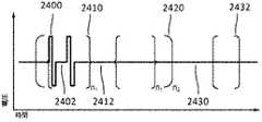
いくつかの実施形態では、絶縁導線は、第2のカテーテルの胴体に配設されてもよい。絶縁導線は、その対応する絶縁が絶縁破壊することなく、少なくとも約700Vの電位を維持するように構成されてもよい。いくつかの実施形態では、パルス波形の階層の第1のレベルを含むパルス波形は、パルスの第1のセットを含んでもよく、各パルスがパルス持続時間を有し、第1の時間間隔が連続パルスを分離する。パルス波形の階層の第2のレベルは、パルスの第2のセットとして複数のパルスの第1のセットを含み、第2のパルス間隔は連続するパルスの第1のセットを分離し、第2の時間間隔が第1の時間間隔の期間の少なくとも3倍であってもよい。パルス波形の階層の第3のレベルは、パルスの第3のセットとして複数のパルスの第2のセットを含み、第3の時間間隔が連続するパルスの第2のセットを分離し、第3の時間間隔が第2のレベルの時間間隔の期間の少なくとも30倍であってもよい。 In some embodiments, the insulated wire may be disposed on the body of the second catheter. The insulated conductor may be configured so that its corresponding insulation maintains a potential of at least about 700V without breakdown. In some embodiments, the pulse waveform that includes the first level of the hierarchy of pulse waveforms may include a first set of pulses, each pulse having a pulse duration, and the first time interval being continuous. Separate the pulses. The second level of the hierarchy of pulse waveforms includes a first set of pulses as the second set of pulses, the second pulse interval separating the first set of consecutive pulses and the second set of pulses. The time interval may be at least three times the duration of the first time interval. A third level of the hierarchy of pulse waveforms includes a second set of pulses as the third set of pulses, separating a second set of pulses with a third time interval in succession, and a third set of pulses. The time interval may be at least 30 times the duration of the second level time interval.
いくつかの実施形態では、不可逆的電気穿孔による心臓不整脈の治療方法は、アブレーションデバイスを患者の左心房の中に前進させるステップと、アブレーションデバイスを第1の構成から第2の構成に移行させるステップとを含んでもよい。アブレーションデバイスは、長手方向軸および中を通る管腔を画定する第1のカテーテルと、第1のカテーテル管腔の遠位端から延在する第2のカテーテルと、 In some embodiments, a method of treating a cardiac arrhythmia by irreversible electroporation comprises advancing an ablation device into a patient's left atrium and transitioning the ablation device from a first configuration to a second configuration. May include and. An ablation device, a first catheter defining a longitudinal axis and a lumen therethrough, a second catheter extending from a distal end of the first catheter lumen,
第1のカテーテル管腔の遠位端に結合した近位部分および第2のカテーテルの遠位端に結合した遠位部分を有するスプラインのセットであって、各スプラインが、スプラインの各々の表面に形成された独立してアドレス可能な電極のセットを含み、各電極に絶縁導線が関連付けられており、絶縁導線が、スプラインのセットの各々の胴体に配設されている、スプラインのセットと、を含んでもよい。第1の構成において、スプラインのセットは、長手方向軸に対して概して平行であってもよい。第2の構成において、スプラインのセットの各スプラインの少なくとも一部は、第2のカテーテルの遠位端に対して遠位に延在する。これらのステップは、パルス波形のセットを生成することと、パルス波形のセットを、左心房の後壁の隣接部分のセットに、第2の構成にあるアブレーションデバイスのスプラインのセットの1つ以上のスプラインを介して送達して、アブレーションゾーンのセットを形成することと、をさらに含んでもよい。 A set of splines having a proximal portion coupled to a distal end of a first catheter lumen and a distal portion coupled to a distal end of a second catheter, each spline being on a respective surface of the spline. A set of splines comprising a set of independently addressable electrodes formed, each electrode being associated with an insulated conductor, the insulated conductor being disposed on each body of the set of splines; May be included. In the first configuration, the set of splines may be generally parallel to the longitudinal axis. In the second configuration, at least a portion of each spline of the set of splines extends distally with respect to the distal end of the second catheter. These steps include generating a set of pulse waveforms, the set of pulse waveforms to a set of adjacent portions of the posterior wall of the left atrium, and one or more sets of splines of the ablation device in the second configuration. Delivering via a spline to form a set of ablation zones.
いくつかの実施形態では、第2の構成において、スプラインのセットは、ループを形成してもよく、その長さに沿って捻られており、その結果、スプラインがその長さに沿ってトーションを有するようになる。いくつかの実施形態では、第2の構成において、スプラインのセットの各スプラインは、第1のカテーテルの長手方向軸に対して約80度未満の角度を有する第2の構成にある長手方向軸を有してもよい。いくつかの実施形態では、スプラインのセットの各スプラインは、等式
に準拠する回転速度u′を有してもよく、式中、lはスプラインの弧長である。いくつかの実施形態では、スプラインの回転速度u′は、等式u′=du/dlに準拠し、式中、lはスプラインに沿った弧長である。いくつかの実施形態では、スプラインのセットの各スプラインの形状は、等式
に準拠してもよく、式中、b=u×uである。In some embodiments, in the second configuration, the set of splines may form a loop and are twisted along its length, such that the spline causes torsion along its length. To have. In some embodiments, in the second configuration, each spline of the set of splines has a longitudinal axis in the second configuration having an angle less than about 80 degrees with respect to the longitudinal axis of the first catheter. You may have. In some embodiments, each spline of the set of splines has the equation
May have a rotational speed u'corresponding to ##EQU1## where l is the arc length of the spline. In some embodiments, the rotational speed u'of the spline complies with the equation u'=du/dl, where l is the arc length along the spline. In some embodiments, the shape of each spline in the set of splines is
In the formula, b=u×u.
いくつかの実施形態では、スプラインのセットの少なくとも一部分は、第2のカテーテルを第1のカテーテルに対して格納することによって、第2のカテーテルの遠位端に対して遠位に前進してもよい。いくつかの実施形態では、各絶縁導線は、その対応する絶縁が絶縁破壊することなく、少なくとも約700Vの電位を維持するように構成されてもよい。 In some embodiments, at least a portion of the set of splines is advanced distally with respect to the distal end of the second catheter by retracting the second catheter with respect to the first catheter. Good. In some embodiments, each insulated conductor may be configured such that its corresponding insulation maintains a potential of at least about 700V without breakdown.
いくつかの実施形態では、スプラインのセットは電極のグループを含んでもよく、電極のグループはスプラインのセットの各スプラインの電極のセットを含んでもよい。本方法は、電極のグループの第1の電極をアノードとして構成することと、電極のグループの第2の電極をカソードとして構成することと、パルス波形を第1の電極および第2の電極に送達することと、をさらに含んでもよい。 In some embodiments, the set of splines may include a group of electrodes, and the group of electrodes may include a set of electrodes for each spline of the set of splines. The method comprises configuring a first electrode of the group of electrodes as an anode, configuring a second electrode of the group of electrodes as a cathode, and delivering a pulse waveform to the first electrode and the second electrode. Doing may further be included.
いくつかの実施形態では、スプラインのセットの第1のスプラインの電極の第1のセットは、アノードとして構成されてもよく、スプラインのセットの第2のスプラインの電極の第2のセットは、カソードとして構成されてもよく、パルス波形は、電極の第1のセットおよび電極の第2のセットに送達されてもよい。 In some embodiments, the first set of electrodes of the first spline of the set of splines may be configured as an anode and the second set of electrodes of the second spline of the set of splines is the cathode. And the pulse waveform may be delivered to the first set of electrodes and the second set of electrodes.
本明細書において、不可逆的電気穿孔により組織をアブレーションするためのパルス電界の選択的かつ迅速な印加のためのシステム、デバイス、および方法が記載される。概して、本明細書に記載のシステム、デバイス、および方法は、目的とされる所望の領域で大きい電界強度を発生させ、他の部分でピーク電界値を減少させて、不必要な組織損傷および電気アーク放電を低減するために使用され得る。本明細書に記載される不可逆的電気穿孔システムは、1つ以上の電圧パルス波形をアブレーションデバイスの電極の選択されたセットに適用して、目的とされる領域にエネルギー(例えば、肺静脈口にある組織のセットのためのアブレーションエネルギー)を送達するように構成された信号生成器およびプロセッサを含んでもよい。本明細書に開示されるパルス波形は、様々な心臓不整脈(例えば、心房細動)の治療的処置を支援することができる。信号生成器によって生成されるパルス波形を送達するために、アブレーションデバイスの1つ以上の電極は、対応する絶縁が絶縁破壊することなく、少なくとも約700Vの電位を維持するように構成されている絶縁導線を有してもよい。電極は、各電極がデバイスのいずれの他の電極からも独立して制御され(例えば、エネルギーを送達し)得るように、独立してアドレス可能であってもよい。このようにして、電極は、組織の電気穿孔のために相乗的に異なるタイミングで異なるエネルギー波形を送達し得る。 Described herein are systems, devices, and methods for selective and rapid application of a pulsed electric field for ablating tissue by irreversible electroporation. In general, the systems, devices, and methods described herein produce large electric field strengths in desired regions of interest and reduce peak electric field values elsewhere to reduce unwanted tissue damage and electrical damage. It can be used to reduce arcing. The irreversible electroporation system described herein applies one or more voltage pulse waveforms to a selected set of electrodes of an ablation device to energize the area of interest (eg, the pulmonary vein ostium). A signal generator and processor configured to deliver ablation energy for a set of tissues). The pulse waveforms disclosed herein can aid in the therapeutic treatment of various cardiac arrhythmias (eg, atrial fibrillation). In order to deliver the pulse waveform generated by the signal generator, one or more electrodes of the ablation device are configured to maintain a potential of at least about 700V without the corresponding insulation breaking down. It may have a conducting wire. The electrodes may be independently addressable, such that each electrode may be controlled (eg, deliver energy) independently of any other electrode in the device. In this way, the electrodes may synergistically deliver different energy waveforms at different times due to electroporation of the tissue.
本明細書で使用される「電気穿孔」という用語は、細胞膜への電界の印加を指し、細胞外環境に対する細胞膜の透過性を変化させることを指す。本明細書で使用される「可逆的電気穿孔」という用語は、細胞膜への電界の印加を指し、細胞外環境に対する細胞膜の透過性を一時的に変化させることを指す。例えば、可逆的電気穿孔を受けている細胞は、電界を除去すると閉じる細胞膜内の1つ以上の細孔の一時的および/または断続的な形成に従い得る。本明細書で使用される「不可逆的電気穿孔」という用語は、細胞膜への電界の印加を指し、細胞外環境に対する細胞膜の透過性を永久的に変化させることを指す。例えば、不可逆的電気穿孔を受けている細胞は、電界を除去しても持続する細胞膜内の1つ以上の細孔の形成に従い得る。 The term "electroporation" as used herein refers to the application of an electric field to a cell membrane and alters the permeability of the cell membrane to the extracellular environment. The term "reversible electroporation", as used herein, refers to the application of an electric field to a cell membrane to temporarily alter the permeability of the cell membrane to the extracellular environment. For example, cells undergoing reversible electroporation may follow the transient and/or intermittent formation of one or more pores within the cell membrane that close upon removal of the electric field. The term "irreversible electroporation" as used herein refers to the application of an electric field to a cell membrane, which permanently alters the permeability of the cell membrane to the extracellular environment. For example, cells undergoing irreversible electroporation may follow the formation of one or more pores in the cell membrane that persists upon removal of the electric field.
本明細書に開示される電気穿孔エネルギー送達のためのパルス波形は、不可逆的電気穿孔に関連する電界閾値を低下させることにより、組織へのエネルギー送達の安全性、効率、および有効性を高め、送達される総エネルギーの低下を伴うより効果的な切除患部をもたらし得る。いくつかの実施形態では、本明細書に開示される電圧パルス波形は階層的であり、入れ子構造を有してもよい。例えば、パルス波形は、関連するタイムスケールを有するパルスの階層的なグループ分けを含んでもよい。いくつかの実施形態では、本明細書に開示される方法、システム、およびデバイスは、「SYSTEMS,APPARATUSES AND METHODS FOR DELIVERY OF ABLATIVE ENERGY TO TISSUE」と題する、2016年10月19日に出願された国際出願PCT/US2016/057664号に記載の方法、システム、およびデバイスのうちの1つ以上を含んでもよく、その内容は、参照によりその全体が本明細書に組み込まれる。 The pulse waveforms for electroporation energy delivery disclosed herein enhance the safety, efficiency, and efficacy of energy delivery to tissue by lowering the electric field threshold associated with irreversible electroporation, It may result in a more effective excision site with a reduction in the total energy delivered. In some embodiments, the voltage pulse waveforms disclosed herein are hierarchical and may have a nested structure. For example, the pulse waveform may include a hierarchical grouping of pulses with associated time scales. In some embodiments, the methods, systems, and devices disclosed herein are internationally filed on October 19, 2016, entitled "SYSTEMS, APPARATUSES AND METHODS FOR DELIVERY OF ABELATIVE TO TISSUE". It may include one or more of the methods, systems, and devices described in application PCT/US2016/057664, the contents of which are incorporated herein by reference in their entirety.
いくつかの実施形態では、システムは、ペーシングされた心拍にパルス波形の生成を同期させるために使用される心臓刺激器をさらに含むことができる。心臓刺激器は、心臓刺激器により心臓を電気的にペーシングし、ペーシングの捕捉を確実にして、心周期の周期性および予測可能性を確立することができる。周期的な心周期の不応期内の時間窓は、電圧パルス波形送達のために選択されてもよい。したがって、心臓の洞調律の混乱を回避するために、心周期の不応期に電圧パルス波形を送達することができる。いくつかの実施形態では、アブレーションデバイスは、1つ以上のカテーテル、ガイドワイヤ、バルーン、および電極を含んでもよい。アブレーションデバイスは、心内腔内にデバイスを位置付けるために、異なる構成(例えば、コンパクトおよび拡張)に移行してもよい。いくつかの実施形態では、システムは、1つ以上のリターン電極を任意に含んでもよい。 In some embodiments, the system can further include a cardiac stimulator used to synchronize the generation of the pulse waveform with the paced heartbeat. The cardiac stimulator can electrically pace the heart with the cardiac stimulator, ensuring pacing capture and establishing the periodicity and predictability of the cardiac cycle. A time window within the refractory period of the periodic cardiac cycle may be selected for voltage pulse waveform delivery. Thus, voltage pulse waveforms can be delivered during the refractory period of the cardiac cycle to avoid disruption of the sinus rhythm of the heart. In some embodiments, the ablation device may include one or more catheters, guidewires, balloons, and electrodes. The ablation device may transition to different configurations (e.g., compact and expanded) to position the device within the endocardial lumen. In some embodiments, the system may optionally include one or more return electrodes.
一般に、組織をアブレーションするために、1つ以上のカテーテルは、脈管構造を通って標的部位まで低侵襲的に前進し得る。心臓用途では、電圧パルス波形が送達される電極は、心外膜デバイスまたは心内膜デバイスに配設されてもよい。本明細書に記載の方法は、デバイスを心臓の左心房の心内腔に導入することと、デバイスを肺静脈口と接触した状態で配設することとを含んでもよい。パルス波形は、生成され、デバイスの1つ以上の電極に送達されて、組織をアブレーションし得る。いくつかの実施形態では、パルス波形は、心臓の洞調律の混乱を回避するために、心臓のペーシング信号と同期して生成することができる。いくつかの実施形態では、電極は、アノード−カソードサブセットで構成されてもよい。パルス波形は、組織アブレーションを支援し、健康な組織への損傷を減らすために階層波形を含んでもよい。 In general, to ablate tissue, one or more catheters may be advanced minimally invasively through the vasculature to a target site. In cardiac applications, the electrodes to which the voltage pulse waveform is delivered may be located on the epicardial or endocardial device. The methods described herein may include introducing the device into the endocardial cavity of the left atrium of the heart and placing the device in contact with the pulmonary vein ostium. A pulse waveform may be generated and delivered to one or more electrodes of the device to ablate tissue. In some embodiments, the pulse waveform can be generated synchronously with the cardiac pacing signal to avoid disruption of the sinus rhythm of the heart. In some embodiments, the electrodes may be composed of an anode-cathode subset. The pulse waveform may include a hierarchical waveform to aid tissue ablation and reduce damage to healthy tissue.
I.システム
概要
本明細書では、不可逆的電気穿孔をもたらす、組織アブレーションを支援するための電圧パルス波形の選択的かつ迅速な適用を介した組織アブレーション用に構成されたシステムおよびデバイスが開示されている。一般に、本明細書に記載の組織をアブレーションするシステムは、信号生成器と、電気穿孔を駆動するためのDC電圧の選択的かつ迅速な印加のための1つ以上の電極を有するアブレーションデバイスとを含んでもよい。本明細書に記載されるように、システムおよびデバイスは、心房細動を処置するために心外膜および/または心内膜で展開されてもよい。電圧は、電極の選択されたサブセットに印加されてもよく、アノード電極とカソード電極との選択のために独立したサブセット選択がある。心臓刺激のためのペーシング信号が生成され、これを使用して、ペーシング信号と同期して信号生成器によってパルス波形が生成されてもよい。I. System Overview Disclosed herein are systems and devices configured for tissue ablation through selective and rapid application of voltage pulse waveforms to assist tissue ablation that results in irreversible electroporation. Generally, the tissue ablation systems described herein include a signal generator and an ablation device having one or more electrodes for selective and rapid application of a DC voltage to drive electroporation. May be included. As described herein, the systems and devices may be deployed epicardially and/or endocardially to treat atrial fibrillation. The voltage may be applied to a selected subset of electrodes, with independent subset selection for the anode and cathode electrode selection. A pacing signal for cardiac stimulation may be generated and used to generate a pulse waveform in synchronization with the pacing signal by a signal generator.
一般に、本明細書に記載のシステムおよびデバイスは、心臓の左心房腔で組織をアブレーションするように構成された1つ以上のカテーテルを含む。図1は、電圧パルス波形を送達するように構成されたアブレーションシステム(100)を示す。システム(100)は、信号生成器(122)と、プロセッサ(124)と、メモリ(126)と、心臓刺激器(128)とを含む装置(120)を含んでもよい。装置(120)は、アブレーションデバイス(110)、ならびにペーシングデバイス(130)および/または任意選択のリターン電極(140)(例えば、ここでは点線で示されるリターンパッド)に任意選択で結合してもよい。 Generally, the systems and devices described herein include one or more catheters configured to ablate tissue in the left atrial chamber of the heart. FIG. 1 shows an ablation system (100) configured to deliver a voltage pulse waveform. The system (100) may include a device (120) that includes a signal generator (122), a processor (124), a memory (126), and a cardiac stimulator (128). The device (120) may optionally be coupled to the ablation device (110) and to the pacing device (130) and/or the optional return electrode (140) (eg, the return pad shown here in dotted lines). ..
信号生成器(122)は、例えば肺静脈口などの組織の不可逆的電気穿孔用のパルス波形を生成するように構成されてもよい。例えば、信号生成器(122)は、電圧パルス波形生成器であり、パルス波形をアブレーションデバイス(110)に送達してもよい。リターン電極(140)が患者に結合することで(例えば、患者の背中に配設されることで)、電流がアブレーションデバイス(110)から患者を通ってリターン電極(140)に流れ、患者からの安全な電流帰還路(図示せず)を提供することが可能となる。プロセッサ(124)は、メモリ(126)、心臓刺激器(128)、およびペーシングデバイス(130)から受信したデータを組み込んで、信号生成器(122)によって生成されるパルス波形のパラメータ(例えば、振幅、幅、デューティサイクルなど)を決定してもよい。メモリ(126)は、信号生成器(122)に、パルス波形の生成および/または心臓ペーシングの同期などのシステム(100)に関連するモジュール、プロセス、および/または機能を実行させる命令をさらに記憶してもよい。例えば、メモリ(126)は、それぞれパルス波形生成および/または心臓ペーシングのためのパルス波形および/または心臓ペーシングデータを記憶するように構成されてもよい。 The signal generator (122) may be configured to generate a pulse waveform for irreversible electroporation of tissue, such as the ostium of the pulmonary vein. For example, the signal generator (122) may be a voltage pulse waveform generator and deliver the pulse waveform to the ablation device (110). The return electrode (140) is coupled to the patient (eg, disposed on the patient's back) so that electrical current flows from the ablation device (110) through the patient to the return electrode (140) and away from the patient. It is possible to provide a safe current return path (not shown). The processor (124) incorporates data received from the memory (126), the cardiac stimulator (128), and the pacing device (130) to provide parameters (eg, amplitude) for the pulse waveform generated by the signal generator (122). , Width, duty cycle, etc.). The memory (126) further stores instructions that cause the signal generator (122) to perform modules, processes, and/or functions associated with the system (100), such as pulse waveform generation and/or cardiac pacing synchronization. May be. For example, the memory (126) may be configured to store pulse waveforms and/or cardiac pacing data for pulse waveform generation and/or cardiac pacing, respectively.
いくつかの実施形態では、アブレーションデバイス(110)は、以下でより詳細に記載されるパルス波形を受信および/または送達するように構成されたカテーテルを含んでもよい。例えば、アブレーションデバイス(110)は、左心房の心内腔内に導入され、1つ以上の電極(112)を1つ以上の肺静脈口に位置合わせするように位置付けられた後、パルス波形を送達して、組織をアブレーションしてもよい。アブレーションデバイス(110)は、1つ以上の電極(112)を含んでもよく、これは、いくつかの実施形態では、独立してアドレス可能な電極のセットであってもよい。各電極は、対応する絶縁が絶縁破壊することなく、少なくとも約700Vの電位を維持するように構成された絶縁導線を含んでもよい。いくつかの実施形態では、導線の各々の絶縁は、絶縁破壊することなく、その厚さ全体で約200V〜約1,500Vの電位差を維持してもよい。例えば、電極(112)は、例えば1つのアノードと1つのカソードとを含むサブセット、2つのアノードと2つのカソードとを含むサブセット、2つのアノードと1つのカソードとを含むサブセット、1つのアノードと2つのカソードとを含むサブセット、3つのアノードと1つのカソードとを含むサブセット、3つのアノードと2つのカソードとを含むサブセットなどの、1つ以上のアノード−カソードのサブセットにグループ分けされてもよい。 In some embodiments, ablation device (110) may include a catheter configured to receive and/or deliver the pulse waveforms described in more detail below. For example, an ablation device (110) is introduced into the endocardial lumen of the left atrium and positioned to align one or more electrodes (112) with one or more pulmonary vein ostia and then pulsed. It may be delivered to ablate tissue. Ablation device (110) may include one or more electrodes (112), which, in some embodiments, may be a set of independently addressable electrodes. Each electrode may include an insulated conductor configured to maintain a potential of at least about 700V without breakdown of the corresponding insulation. In some embodiments, the insulation of each of the conductors may maintain a potential difference of about 200V to about 1500V across its thickness without breakdown. For example, the electrode (112) may be, for example, a subset including one anode and one cathode, a subset including two anodes and two cathodes, a subset including two anodes and one cathode, one anode and two. One or more anode-cathode subsets may be grouped, such as a subset including one cathode, a subset including three anodes and one cathode, a subset including three anodes and two cathodes, and the like.
ペーシングデバイス(130)は、患者に好適に結合し(図示せず)、心臓刺激のために装置(120)の心臓刺激器(128)によって生成された心臓ペーシング信号を受信するように構成されてもよい。ペーシング信号の表示は、心臓刺激器(128)によって信号生成器(122)に送信されてもよい。ペーシング信号に基づいて、電圧パルス波形の表示は、プロセッサ(124)によって選択、計算、および/または別の方法で識別され、信号生成器(122)によって生成されてもよい。いくつかの実施形態では、信号生成器(122)は、ペーシング信号の表示と同期して(例えば、共通の不応性窓内で)パルス波形を生成するように構成される。例えば、いくつかの実施形態では、共通の不応性窓は、心室ペーシング信号の実質的に直後に(または非常に小さな遅延の後に)開始し、その後約250ミリ秒以下の期間続く。そのような実施形態では、パルス波形全体がこの期間内に送達されてもよい。 The pacing device (130) is suitably coupled to a patient (not shown) and is configured to receive a cardiac pacing signal generated by a cardiac stimulator (128) of the device (120) for cardiac stimulation. Good. An indication of the pacing signal may be sent to the signal generator (122) by the cardiac stimulator (128). Based on the pacing signal, an indication of the voltage pulse waveform may be selected, calculated, and/or otherwise identified by the processor (124) and generated by the signal generator (122). In some embodiments, the signal generator (122) is configured to generate a pulse waveform in synchronization with the display of the pacing signal (eg, within a common refractory window). For example, in some embodiments, the common refractory window starts substantially immediately (or after a very small delay) of the ventricular pacing signal and continues for a period of about 250 milliseconds or less thereafter. In such an embodiment, the entire pulse waveform may be delivered within this period.
プロセッサ(124)は、命令またはコードのセットを実施および/または実行するように構成された任意の好適な処理デバイスであってもよい。プロセッサは、例えば、汎用プロセッサ、フィールドプログラマブルゲートアレイ(FPGA)、特定用途向け集積回路(ASIC)、デジタル信号プロセッサ(DSP)、および/または同様のものであってもよい。プロセッサは、システムおよび/またはそれに関連するネットワーク(図示せず)に関連するアプリケーションプロセスおよび/または他のモジュール、プロセスおよび/または機能を実施および/または実行するように構成されてもよい。基礎となるデバイス技術は、相補型金属酸化物半導体(CMOS)などの金属酸化物半導体電界効果トランジスタ(MOSFET)技術、エミッタ結合ロジック(ECL)などのバイポーラ技術、ポリマー技術(例えば、シリコン共役ポリマーおよび金属共役ポリマー金属構造)、アナログとデジタルの混合など、様々な構成要素の種類で提供されてもよい。 Processor (124) may be any suitable processing device configured to implement and/or execute a set of instructions or code. The processor may be, for example, a general purpose processor, a field programmable gate array (FPGA), an application specific integrated circuit (ASIC), a digital signal processor (DSP), and/or the like. The processor may be configured to implement and/or execute application processes and/or other modules, processes and/or functions associated with the system and/or its associated network (not shown). The underlying device technologies include metal oxide semiconductor field effect transistor (MOSFET) technology such as complementary metal oxide semiconductor (CMOS), bipolar technology such as emitter coupled logic (ECL), polymer technology (eg, silicon conjugated polymer and Metal conjugated polymers (metal structures), mixed analog and digital, etc. may be provided in various component types.
メモリ(126)は、データベース(図示せず)を含んでもよく、例えば、ランダムアクセスメモリ(RAM)、メモリバッファ、ハードドライブ、消去可能プログラマブル読み出し専用メモリ(EPROM)、電気的に消去可能な読み取り専用メモリ(EEPROM)、読み取り専用メモリ(ROM)、フラッシュメモリなどであってもよい。メモリ(126)は、プロセッサ(124)に、パルス波形生成、および/または心臓ペーシングなど、システム(100)に関連付けられたモジュール、プロセス、および/または機能を実行させる命令を記憶させてもよい。 The memory (126) may include a database (not shown), such as random access memory (RAM), memory buffers, hard drives, erasable programmable read only memory (EPROM), electrically erasable read only. It may be a memory (EEPROM), a read-only memory (ROM), a flash memory, or the like. The memory (126) may store instructions that cause the processor (124) to perform modules, processes, and/or functions associated with the system (100), such as pulse waveform generation and/or cardiac pacing.
システム(100)は、例えば、1つ以上のネットワークを介して他のデバイス(図示せず)と通信してもよく、ネットワークの各々は、いずれの種類のネットワークであってもよい。無線ネットワークとは、あらゆる種類のケーブルで接続されていないあらゆる種類のデジタルネットワークを指す。ただし、無線ネットワークは、インターネット、他の通信事業者の音声およびデータネットワーク、ビジネスネットワーク、ならびにパーソナルネットワークと接続するために、有線ネットワークに接続する場合がある。有線ネットワークは、典型的には、銅線のツイストペア、同軸ケーブル、または光ファイバーケーブルで搬送される。ワイドエリアネットワーク(WAN)、メトロポリタンエリアネットワーク(MAN)、ローカルエリアネットワーク(LAN)、キャンパスエリアネットワーク(CAN)、グローバルエリアネットワーク(GAN)、例えば、インターネット、および仮想プライベートネットワーク(VPN)を含む、様々な種類の有線ネットワークがある。以下、ネットワークとは、典型的にはインターネットを介して相互接続される、組み合わせた無線、有線、公衆、およびプライベートのデータネットワークの任意の組み合わせを指し、統合されたネットワーキングおよび情報アクセスソリューションを提供する。 The system (100) may communicate with other devices (not shown) via, for example, one or more networks, each of which may be any type of network. A wireless network is any type of digital network that is not connected by any type of cable. However, wireless networks may connect to wired networks to connect to the Internet, voice and data networks of other carriers, business networks, and personal networks. Wired networks are typically carried over twisted copper wire pairs, coaxial cables, or fiber optic cables. Various, including Wide Area Networks (WANs), Metropolitan Area Networks (MANs), Local Area Networks (LANs), Campus Area Networks (CANs), Global Area Networks (GANs) such as the Internet and Virtual Private Networks (VPNs). There are various types of wired networks. Hereinafter, network refers to any combination of combined wireless, wireline, public, and private data networks, typically interconnected via the Internet, to provide an integrated networking and information access solution. ..
アブレーションデバイス
本明細書に記載のシステムは、心房細動を処置するために心臓の左心房腔で組織をアブレーションするように構成された1つ以上の多電極アブレーションデバイスを含んでもよい。図2は、カテーテル(210)およびカテーテル(210)の管腔内で摺動可能なガイドワイヤ(220)を含むアブレーションデバイス(200)(例えば、アブレーションデバイス(110)に構造的および/または機能的に類似したもの)の斜視図である。ガイドワイヤ(220)は、非線形の遠位部分(222)を含んでもよく、カテーテル(210)は、使用中にガイドワイヤ(220)の上に配設されるように構成されてもよい。ガイドワイヤ(220)の遠位部分(222)は、患者の管腔におけるカテーテル(210)の配置を支援するように形状決定されてもよい。例えば、ガイドワイヤ(220)の遠位部分(222)の形状は、図15でより詳細に説明されるように、肺静脈口におよび/またはその近辺に配置されるように構成されてもよい。ガイドワイヤ(220)の遠位部分(222)は、組織への外傷を低減する(例えば、組織穿刺の可能性を防止および/または低減する)非侵襲的形状を含み、かつ/または非侵襲的形状で形成されてもよい。例えば、ガイドワイヤ(220)の遠位部分(222)は、非線形の形状、例えば、円形、ループ(図2に示されているとおり)、楕円体、または任意の他の幾何形状を含んでもよい。いくつかの実施形態では、ガイドワイヤ(220)は、非線形の形状を有するガイドワイヤが、カテーテル(210)に配設されたときにカテーテル(210)の管腔に一致し、カテーテル(210)から出て前進するときに非線形の形状を再形成あるいは回復するように、弾性であるように構成されてもよい。他の実施形態では、カテーテル(210)は、同様に、カテーテル(210)のシースを通した前進を支援するためなど、弾性であるように構成されてもよい(図示せず)。成形されたガイドワイヤ(220)の遠位部分(222)は、ガイドワイヤ(220)およびカテーテル(210)の他の部分に対して角度が付いていてもよい。カテーテル(210)およびガイドワイヤ(220)は、心内腔(例えば、左心房)への前進のためにサイズ決定されてもよい。成形されたガイドワイヤ(220)の遠位部分(222)の直径は、カテーテル(230)が配設されることになる管腔の直径とほぼ同じであってもよい。Ablation Devices The systems described herein may include one or more multi-electrode ablation devices configured to ablate tissue in the left atrial chamber of the heart to treat atrial fibrillation. FIG. 2 illustrates an ablation device (200) that includes a catheter (210) and a guidewire (220) slidable within the lumen of the catheter (210) (eg, structurally and/or functionally to an ablation device (110). Is a perspective view (similar to FIG. Guidewire (220) may include a non-linear distal portion (222) and catheter (210) may be configured to be disposed over guidewire (220) during use. The distal portion (222) of the guidewire (220) may be shaped to assist in placement of the catheter (210) in the patient's lumen. For example, the shape of the distal portion (222) of the guidewire (220) may be configured to be placed at and/or near the pulmonary vein ostium, as described in more detail in FIG. .. The distal portion (222) of the guidewire (220) includes a non-invasive shape that reduces trauma to tissue (eg, prevents and/or reduces the likelihood of tissue puncture) and/or is non-invasive. It may be formed in a shape. For example, the distal portion (222) of the guidewire (220) may include a non-linear shape, eg, circular, loop (as shown in FIG. 2), ellipsoid, or any other geometric shape. .. In some embodiments, the guidewire (220) conforms to the lumen of the catheter (210) when the guidewire having a non-linear shape is disposed on the catheter (210), It may be configured to be elastic so as to reform or recover the non-linear shape as it exits and advances. In other embodiments, the catheter (210) may also be configured to be elastic (not shown), such as to aid advancement of the catheter (210) through the sheath. The distal portion (222) of the shaped guidewire (220) may be angled with respect to the guidewire (220) and other portions of the catheter (210). Catheter (210) and guidewire (220) may be sized for advancement into the intracardiac lumen (eg, the left atrium). The diameter of the distal portion (222) of the shaped guidewire (220) may be about the same as the diameter of the lumen in which the catheter (230) will be placed.
カテーテル(210)は、使用中にガイドワイヤ(220)の上に配設されるように、ガイドワイヤ(220)の上を摺動可能に前進してもよい。管腔(例えば、肺静脈口付近)に配設されたガイドワイヤ(220)の遠位部分(222)は、カテーテル(210)の遠位部分の前進に対するバックストップとして働き得る。カテーテル(210)の遠位部分は、管腔(例えば、肺静脈口)の内側半径方向表面に接触するように構成された電極(212)(例えば、電極(複数可)(112)に構造的および/または機能的に類似したもの)のセットを含んでもよい。例えば、電極(212)は、肺静脈口に接触するように構成された電極のほぼ円形の配列を含んでもよい。図2に示されるように、1つ以上の電極(212)は、カテーテルシャフトに沿って配設された一連の金属バンドまたはリングを含み、ともに電気接続されてもよい。例えば、アブレーションデバイス(200)は、複数のバンドを有する単一の電極、各電極がそれ自体のバンドを有する1つ以上の電極、およびそれらの組み合わせを含んでもよい。いくつかの実施形態では、電極(212)は、ガイドワイヤ(220)の遠位部分(222)の形状に一致するように成形されてもよい。カテーテルシャフトは、可撓性を強化するために、電極間に可撓性部分を含んでもよい。他の実施形態では、1つ以上の電極(212)は、可撓性を強化するために、螺旋巻きを含んでもよい。 The catheter (210) may be slidably advanced over the guidewire (220) so that it is disposed over the guidewire (220) during use. A distal portion (222) of guidewire (220) disposed in the lumen (eg, near the ostium of the pulmonary vein) can serve as a backstop for advancement of the distal portion of catheter (210). The distal portion of the catheter (210) is structurally attached to an electrode (212) (eg, electrode(s) (112)) configured to contact the inner radial surface of the lumen (eg, pulmonary vein ostium). And/or functionally similar). For example, the electrode (212) may include a generally circular array of electrodes configured to contact the pulmonary vein ostium. As shown in FIG. 2, one or more electrodes (212) may include a series of metal bands or rings disposed along the catheter shaft and electrically connected together. For example, ablation device (200) may include a single electrode having multiple bands, one or more electrodes with each electrode having its own band, and combinations thereof. In some embodiments, the electrodes (212) may be shaped to conform to the shape of the distal portion (222) of the guidewire (220). The catheter shaft may include flexible portions between the electrodes to enhance flexibility. In other embodiments, one or more electrodes (212) may include spiral windings to enhance flexibility.
本明細書で考察されるアブレーションデバイスの電極の各々は、カテーテルの近位部分に結合したハンドル(図示せず)に繋がる絶縁導線(図示せず)に接続してもよい。導線の各々の絶縁は、絶縁破壊することなく、その厚さ全体で少なくとも700Vの電位差を維持してもよい。他の実施形態では、各導線の絶縁は、絶縁破壊することなく、その間の厚さ全体で、間のすべての値および部分範囲を含めて約200V〜約2000Vの間の電位差を維持してもよい。これにより、電極は、電気エネルギーを効率的に送達でき、組織を不可逆的電気穿孔によりアブレーションできるようになる。電極は、図1に関して上で考察したように、例えば、信号生成器(122)によって生成されたパルス波形を受信してもよい。他の実施形態では、ガイドワイヤ(220)は、アブレーションデバイス(200)と分離していてもよい(例えば、アブレーションデバイス(200)は、カテーテル(210)を含むが、ガイドワイヤ(220)を含まない)。例えば、ガイドワイヤ(220)は、それ自体によって心内腔の中に前進してもよく、その後、カテーテル(210)がガイドワイヤ(220)上で心内腔の中に前進してもよい。 Each of the electrodes of the ablation device discussed herein may be connected to an insulated lead (not shown) that leads to a handle (not shown) that is coupled to the proximal portion of the catheter. The insulation of each of the conductors may maintain a potential difference of at least 700V throughout its thickness without breakdown. In another embodiment, the insulation of each conductor maintains a potential difference between about 200V to about 2000V across its thickness without breakdown, including all values and subranges therebetween. Good. This allows the electrodes to efficiently deliver electrical energy and ablate tissue by irreversible electroporation. The electrodes may receive, for example, a pulse waveform generated by a signal generator (122), as discussed above with respect to FIG. In other embodiments, guidewire (220) may be separate from ablation device (200) (eg, ablation device (200) includes catheter (210), but includes guidewire (220). Absent). For example, the guidewire (220) may be advanced by itself into the heart chamber, and then the catheter (210) may be advanced over the guidewire (220) into the heart chamber.
図3は、電極(314)のセットがカテーテル(310)の遠位部分(312)に沿って設けられたカテーテル(310)を含むアブレーションデバイス(300)(例えば、アブレーションデバイス(110)に構造的および/または機能的に類似したもの)の別の実施形態の斜視図である。カテーテル(310)の遠位部分(312)は、非線形であり、ほぼ円形の形状を形成してもよい。電極(314)のセットは、カテーテル(310)の非線形の遠位部分(312)に沿って配設されてもよく、電極(314)のほぼ円形の配列を形成してもよい。使用中、電極(314)は、図16に関してより詳細に記載されているように、パルス波形を送達して、組織をアブレーションするために、肺静脈口に配設されてもよい。成形されたカテーテル(310)の遠位部分(312)は、カテーテル(310)の他の位置に対して角度が付いていてもよい。例えば、カテーテル(310)の遠位部分(312)は、カテーテル(310)の隣接した位置にほぼ垂直であってもよい。いくつかの実施形態では、ハンドル(図示せず)は、カテーテル(310)の近位部分に結合してもよく、カテーテル(310)の遠位部分(312)の形状を改変するように構成された曲げ機構(例えば、1つ以上のプルワイヤ(図示せず))を含んでもよい。例えば、ハンドルのプルワイヤの操作により、カテーテル(310)の遠位部分(312)の円形の形状の外周が増加または減少し得る。カテーテル(310)の遠位部分(312)の直径を改変して、電極(314)を、肺静脈口の付近におよび/または肺静脈口と接触して(例えば、肺静脈の内側半径方向表面と接触して)配設できるようにしてもよい。電極(314)は、一連の金属バンドまたはリングを含み、独立してアドレス可能であってもよい。 FIG. 3 is structurally directed to an ablation device (300) (eg, ablation device (110)) that includes a catheter (310) having a set of electrodes (314) provided along a distal portion (312) of the catheter (310). And/or functionally similar) perspective views of another embodiment. The distal portion (312) of the catheter (310) is non-linear and may form a generally circular shape. The set of electrodes (314) may be disposed along the non-linear distal portion (312) of the catheter (310) and may form a generally circular array of electrodes (314). In use, electrode (314) may be placed at the ostium of the pulmonary vein to deliver a pulse waveform and ablate tissue, as described in more detail with respect to FIG. The distal portion (312) of the shaped catheter (310) may be angled with respect to other locations of the catheter (310). For example, the distal portion (312) of the catheter (310) may be substantially perpendicular to the adjacent location of the catheter (310). In some embodiments, a handle (not shown) may be coupled to the proximal portion of catheter (310) and is configured to modify the shape of the distal portion (312) of catheter (310). Bending mechanism (eg, one or more pull wires (not shown)). For example, manipulation of the pull wire of the handle may increase or decrease the circumference of the circular shape of the distal portion (312) of the catheter (310). The diameter of the distal portion (312) of the catheter (310) is modified so that the electrode (314) is in the vicinity of and/or in contact with the pulmonary vein ostium (eg, the inner radial surface of the pulmonary vein). May be provided). Electrodes (314) include a series of metal bands or rings and may be independently addressable.
いくつかの実施形態では、パルス波形は、アノードとカソードとのセットで構成された電極(314)間に適用され得る。例えば、隣接したまたはほぼ正反対の電極対は、アノード−カソードセットとしてともに作動してもよい。本明細書に開示のパルス波形のいずれも、アノード−カソード電極のシーケンスに漸進的にまたは連続的に適用され得ることを理解されたい。 In some embodiments, a pulse waveform may be applied between electrodes (314) configured with an anode and cathode set. For example, adjacent or nearly opposite electrode pairs may operate together as an anode-cathode set. It should be appreciated that any of the pulse waveforms disclosed herein may be applied to the anode-cathode electrode sequence in a gradual or continuous manner.
図4は、成形された非線形の遠位部分(422)を有するカテーテル(410)およびガイドワイヤ(420)を含むアブレーションデバイス(400)(例えば、アブレーションデバイス(110)に構造的および/または機能的に類似したもの)のさらに別の実施形態の斜視図である。ガイドワイヤ(420)は、カテーテル(410)の管腔内で摺動可能であってもよい。ガイドワイヤ(420)は、カテーテル(410)の管腔を通って前進してもよく、ガイドワイヤ(420)の遠位部分(422)は、ほぼ円形の形状であってもよい。ガイドワイヤ(420)の遠位部分(422)の形状および/または直径は、図3に関して上に記載したように、曲げ機構を使用して改変してもよい。カテーテル(410)は、曲げられるように可撓性であってもよい。いくつかの実施形態では、カテーテル(410)および/またはガイドワイヤ(420)は、それらが配設される管腔に一致し、管腔から出て前進するときに二次形状をとるように、弾性であるように構成されてもよい。ガイドワイヤ(420)のサイズを改変し、カテーテル(410)の偏向を操作することにより、ガイドワイヤ(420)の遠位部分(422)が肺静脈口などの標的の組織部位に位置付けられ得る。カテーテル(410)の遠位端(412)は、カテーテル(410)がカテーテル(410)の管腔内にあるガイドワイヤ(420)の部分を電気的に絶縁し得るように、ガイドワイヤ(420)が延在を始める場所を除いて密封されてもよい。例えば、いくつかの実施形態では、カテーテル(410)の遠位端(412)は、封止を含んでもよく、この封止は、力を適用したときにガイドワイヤ(420)の通過を許容して、封止とガイドワイヤ(420)との間に圧縮ホールド(液密であってもよい)を形成する開口部を有する。 FIG. 4 illustrates an ablation device (400) that includes a catheter (410) having a shaped non-linear distal portion (422) and a guide wire (420) (eg, structural and/or functional to an ablation device (110). Is a perspective view of yet another embodiment (similar to FIG. Guidewire (420) may be slidable within the lumen of catheter (410). Guidewire (420) may be advanced through the lumen of catheter (410) and the distal portion (422) of guidewire (420) may be generally circular in shape. The shape and/or diameter of the distal portion (422) of the guidewire (420) may be modified using a bending mechanism, as described above with respect to FIG. The catheter (410) may be flexible so that it can be bent. In some embodiments, the catheter (410) and/or guidewire (420) conforms to the lumen in which they are placed and assumes a secondary shape when advanced out of the lumen. It may be configured to be elastic. By modifying the size of the guidewire (420) and manipulating the deflection of the catheter (410), the distal portion (422) of the guidewire (420) can be positioned at a target tissue site, such as the pulmonary ostium. The distal end (412) of the catheter (410) is adapted to allow the catheter (410) to electrically insulate the portion of the guidewire (420) within the lumen of the catheter (410). May be sealed except where it begins to extend. For example, in some embodiments, the distal end (412) of catheter (410) may include a seal that allows passage of guidewire (420) when a force is applied. And has an opening that forms a compression hold (which may be liquid tight) between the seal and the guide wire (420).
いくつかの実施形態では、露出したガイドワイヤ(420)の遠位部分(422)は、電極に結合してもよく、パルス波形を信号生成器から受信し、パルス波形を使用中に組織に送達するように構成されてもよい。例えば、ガイドワイヤ(420)の近位端は、好適な導線に結合し、図1の信号生成器(122)に接続してもよい。ガイドワイヤ(420)の遠位部分(422)は、肺静脈口に位置付けられ得るようにサイズ決定され得る。例えば、成形されたガイドワイヤ(420)の遠位部分(422)の直径は、肺静脈口の直径とほぼ同じであってもよい。成形されたガイドワイヤ(420)の遠位部分(422)は、ガイドワイヤ(420)およびカテーテル(410)の他の部分に対して角度が付いていてもよい。 In some embodiments, the distal portion (422) of the exposed guidewire (420) may be coupled to an electrode, receiving a pulse waveform from a signal generator and delivering the pulse waveform to tissue during use. May be configured to do so. For example, the proximal end of guidewire (420) may be coupled to a suitable conductor and connected to the signal generator (122) of FIG. The distal portion (422) of the guidewire (420) can be sized so that it can be positioned at the pulmonary vein ostium. For example, the diameter of the distal portion (422) of the shaped guidewire (420) may be about the same as the diameter of the pulmonary vein ostium. The distal portion (422) of the shaped guidewire (420) may be angled with respect to the guidewire (420) and other portions of the catheter (410).
ガイドワイヤ(420)は、ステンレス鋼、ニチノール、白金、または他の好適な生体適合性材料を含んでもよい。いくつかの実施形態では、ガイドワイヤ(420)の遠位部分(422)は、ガイドワイヤ(420)に物理的および電気的に連結した白金コイルを含んでもよい。白金コイルは、電圧パルス波形の送達用に構成された電極であってもよい。白金は、放射線不透過性であり、その使用により、可撓性が増大し、心内腔におけるアブレーションデバイス(400)の前進および位置付けが支援され得る。 Guidewire (420) may comprise stainless steel, nitinol, platinum, or other suitable biocompatible material. In some embodiments, the distal portion (422) of guidewire (420) may include a platinum coil physically and electrically coupled to guidewire (420). The platinum coil may be an electrode configured for delivery of a voltage pulse waveform. Platinum is radiopaque and its use may increase flexibility and aid in the advancement and positioning of the ablation device (400) in the endocardial cavity.
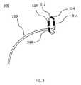
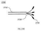
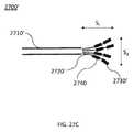
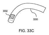
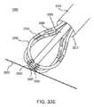
図5は、絶縁導線セグメント(510、512、514、516)の対から各々延在する電極(520、522、524、526)のセットを含む、アブレーションデバイス(500)(例えば、アブレーションデバイス(110)に構造的および/または機能的に類似したもの)の花形の遠位部分の詳細斜視図である。絶縁されていない電極(例えば、導線セグメント(510、512)および電極(526))に結合した隣接する絶縁導線セグメントの各対は、ループを形成する(図5は4つのループのセットを示す)。アブレーションデバイス(500)の遠位端部にあるループのセットは、パルス波形を組織に送達するように構成されてもよい。アブレーションデバイス(500)は、図5に示されるように、デバイス(500)の遠位端で分岐して、それぞれの露出した電極(520、522、524、526)に接続する絶縁導線セグメント(510、512、514、516)のセットを含んでもよい。電極(520、522、524、526)は、電気伝導体の露出した部分を含んでもよい。いくつかの実施形態では、電極(520、522、524、526)のうちの1つ以上は、白金コイルを含んでもよい。1つ以上のセグメント(510、512、514、516)は、デバイス(500)の遠位部分のサイズおよび/または形状を制御するためにハンドル(図示せず)から制御される曲げ機構(例えば、支柱、プルワイヤなど)に結合してもよい。 FIG. 5 illustrates an ablation device (500) (eg, ablation device (110) that includes a set of electrodes (520, 522, 524, 526) each extending from a pair of insulated wire segments (510, 512, 514, 516). 3) is a detailed perspective view of a flower-shaped distal portion (structurally and/or functionally similar) to FIG. Each pair of adjacent insulated conductor segments coupled to non-insulated electrodes (eg, conductor segment (510, 512) and electrode (526)) forms a loop (FIG. 5 shows a set of four loops). .. The set of loops at the distal end of the ablation device (500) may be configured to deliver the pulse waveform to the tissue. The ablation device (500) branches off at the distal end of the device (500) and connects to each exposed electrode (520, 522, 524, 526) as shown in FIG. , 512, 514, 516). The electrodes (520, 522, 524, 526) may include exposed portions of electrical conductors. In some embodiments, one or more of the electrodes (520, 522, 524, 526) may include a platinum coil. One or more segments (510, 512, 514, 516) include a bending mechanism (eg, controlled) from a handle (not shown) to control the size and/or shape of the distal portion of device (500). Struts, pull wires, etc.).
電極(520、522、524、526)は、可撓性であり、肺静脈口に隣接したものなど、心内腔中への前進のためのコンパクトな第1の構成を形成してもよい。所望の場所に配設されると、電極(520、522、524、526)は、図5に示されるように、シースなどの管腔から出て前進するときに、拡張した第2の構成に移行して、花形の遠位部分を形成してもよい。他の実施形態では、絶縁導線セグメント(510、512、514、516)および電極(520、522、524、526)は、管腔(例えば、シース)から出て前進するときに、付勢され、外向きに拡張して(例えば、跳ね開いて)第2の構成となり、デバイス(500)を運搬する。電極(520、522、524、526)は、独立してアドレス可能であってもよく、各々、対応する絶縁が絶縁破壊することなく、少なくとも約700Vの電位を維持するように構成された絶縁導線を有してもよい。他の実施形態では、各導線の絶縁は、絶縁破壊することなく、その厚さ全体で約200V〜約2000Vの間の電位差を維持してもよい。 The electrodes (520, 522, 524, 526) are flexible and may form a compact first configuration for advancement into the cardiac lumen, such as adjacent to the pulmonary vein ostium. Once placed in the desired location, the electrodes (520, 522, 524, 526) are in an expanded, second configuration when advanced out of a lumen, such as a sheath, as shown in FIG. It may be transitioned to form a flower-shaped distal portion. In other embodiments, the insulated wire segments (510, 512, 514, 516) and electrodes (520, 522, 524, 526) are biased as they advance out of the lumen (eg, sheath), Expand outward (eg, flip open) into a second configuration to carry the device (500). The electrodes (520, 522, 524, 526) may be independently addressable, each insulated wire configured to maintain a potential of at least about 700V without breakdown of the corresponding insulation. May have. In other embodiments, the insulation of each conductor may maintain a potential difference between about 200V and about 2000V across its thickness without breakdown.
いくつかの実施形態では、アブレーションデバイス(5000)は、電極(520、522、524、526)のセットを介して、使用中にパルス波形を組織に送達するように構成されてもよい。いくつかの実施形態では、パルス波形は、アノードとカソードとのセットで構成された電極(520、522、524、526)間に適用され得る。例えば、ほぼ正反対の電極対(例えば、電極(520、524)および(522、526))は、アノード−カソード対としてともに作動してもよい。他の実施形態では、隣接する電極は、アノード−カソード対として構成されてもよい。例として、電極のセットの1の電極(520)は、アノードとして構成されてもよく、第2の電極(522)は、カソードとして構成されてもよい。 In some embodiments, ablation device (5000) may be configured to deliver a pulsed waveform to tissue during use via a set of electrodes (520, 522, 524, 526). In some embodiments, the pulse waveform may be applied between electrodes (520, 522, 524, 526) configured with an anode and cathode set. For example, diametrically opposed electrode pairs (eg, electrodes (520, 524) and (522, 526)) may work together as an anode-cathode pair. In other embodiments, adjacent electrodes may be configured as an anode-cathode pair. As an example, one electrode (520) of the set of electrodes may be configured as an anode and the second electrode (522) may be configured as a cathode.
図6〜9E、26A〜27C、および28は、組織をアブレーションし、肺静脈を電気的に絶縁するために電極のセットを使用して電圧パルス波形を送達するように構成され得るアブレーションデバイス(例えば、アブレーションデバイス(110)に構造的および/または機能的に類似したもの)の追加の実施形態を示す。これらの実施形態のいくつかでは、アブレーションデバイスの電極が外向きに拡張して組織の管腔(例えば、肺静脈口)に接触するように、アブレーションデバイスを第1の構成から第2の構成に移行させてもよい。 6-9E, 26A-27C, and 28 may be configured to deliver voltage pulse waveforms using a set of electrodes to ablate tissue and electrically insulate pulmonary veins (eg, , An additional embodiment of structural and/or functional similarities to ablation device (110). In some of these embodiments, the ablation device is moved from the first configuration to the second configuration such that the electrodes of the ablation device expand outward to contact the lumen of tissue (eg, the ostium of the pulmonary vein). You may transfer.
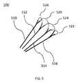
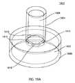
図6は、デバイス(600)の近位端にあるカテーテルシャフト(610)、デバイス(600)の遠位キャップ(612)、およびそれに結合したスプライン(614)のセットを含む、アブレーションデバイス(600)の実施形態の側面図である。遠位キャップ(612)は、組織への外傷を減少させるために非侵襲的形状を含んでもよい。スプライン(614)のセットの近位端は、カテーテルシャフト(610)の遠位端に結合されてもよく、スプライン(614)のセットの遠位端は、デバイス(600)の遠位キャップ(612)につながれてもよい。アブレーションデバイス(600)は、スプライン(614)のセットの1つ以上のスプラインを介して、使用中にパルス波形を組織に送達するように構成されてもよい。本明細書で使用される場合、「スプライン」および「スパイン」は、同じ意味で使用されてもよい。いくつかの実施形態では、装置は、長手方向軸を画定するカテーテルを含んでもよい。 FIG. 6 shows an ablation device (600) including a catheter shaft (610) at the proximal end of the device (600), a distal cap (612) of the device (600), and a set of splines (614) coupled thereto. 2 is a side view of the embodiment of FIG. Distal cap (612) may include a non-invasive shape to reduce trauma to tissue. The proximal end of the set of splines (614) may be coupled to the distal end of the catheter shaft (610), and the distal end of the set of splines (614) may be coupled to the distal cap (612) of the device (600). ) May be connected to. The ablation device (600) may be configured to deliver a pulse waveform to the tissue during use via one or more splines in the set of splines (614). As used herein, "spline" and "spine" may be used interchangeably. In some embodiments, the device may include a catheter that defines a longitudinal axis.
アブレーションデバイス(600)の各スプライン(614)は、スプライン(614)の表面に形成された1つ以上の繋がって配線されている、またはある場合には独立してアドレス指定可能な電極(616)を含んでもよい。各電極(616)は、対応する絶縁が絶縁破壊することなく、少なくとも約700Vの電位を維持するように構成された絶縁導線を含むことができる。他の実施形態では、各導線の絶縁は、絶縁破壊することなく、その厚さ全体で約200V〜約2000Vの間の電位差を維持してもよい。各スプライン(614)は、スプライン(614)の胴体に(例えば、スプライン(614)の管腔内に)形成された各電極(616)の絶縁導線を含んでもよい。単一のスプライン上の電極がともに配線されている場合、単一の絶縁導線は、スプライン上の異なる電極に接続しているストランドを保持していてもよい。図6は、各スプライン(614)が隣接するスプライン(614)の電極(616)とほぼ同じサイズ、形状、および間隔を有する一対の電極(616)を含む、スプライン(614)のセットを示す。他の実施形態では、電極(616)のサイズ、形状、および間隔は異なっていてもよい。 Each spline (614) of the ablation device (600) is wired in one or more tethers formed on the surface of the spline (614), or in some cases independently addressable electrodes (616). May be included. Each electrode (616) may include an insulated conductor configured to maintain a potential of at least about 700V without the corresponding insulation breaking down. In other embodiments, the insulation of each conductor may maintain a potential difference between about 200V and about 2000V across its thickness without breakdown. Each spline (614) may include an insulated lead wire for each electrode (616) formed in the body of the spline (614) (eg, within the lumen of the spline (614)). If the electrodes on a single spline are wired together, the single insulated conductor may carry strands connecting to different electrodes on the spline. FIG. 6 illustrates a set of splines (614), where each spline (614) includes a pair of electrodes (616) having approximately the same size, shape, and spacing as the electrodes (616) of the adjacent splines (614). In other embodiments, the electrodes (616) may vary in size, shape, and spacing.
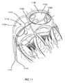
本明細書に記載されるアブレーションデバイスの各々、ならびに特に図6〜9E、26A〜27C、および28に記載されるアブレーションデバイスについて、スプラインのセットの各スプラインは、可撓性の湾曲を含んでもよい。スプラインの最小曲率半径は、約1cm以上の範囲であり得る。例えば、スプラインのセットは、アブレーションデバイスの遠位部分で送達アセンブリを形成してもよく、スプラインのセットがアブレーションデバイスの長手方向軸から半径方向外向きにたわむ第1の構成と、スプラインのセットがアブレーションデバイスの長手方向軸にほぼ平行に配列される第2の構成との間で移行するように構成されてもよい。このようにして、スプラインは、心内腔の幾何形状により容易に一致し得る。一般に、スプラインの「バスケット」は、バスケットの一方の端(仮に遠位端)がバスケットの他方の端(仮に近位端)より膨らんでいるように、シャフトの長さに沿って非対称の形状を有し得る。送達アセンブリは、肺静脈口と接触して第1の構成で配設され、パルス波形の送達前に第2の構成に移行してもよい。これらの実施形態のうちのいくつかでは、ハンドルがスプラインのセットに結合してもよく、ハンドルは、スプラインのセットの第1の構成と第2の構成との間の移行を発動するように構成される。いくつかの実施形態では、電極のセットの少なくとも2つの電極の導線は、例えばハンドル内など、アブレーションデバイスの近位部分またはその付近で電気的に結合してもよい。 For each of the ablation devices described herein, and particularly for the ablation devices described in FIGS. 6-9E, 26A-27C, and 28, each spline of the set of splines may include a flexible curvature. .. The minimum radius of curvature of the spline can range from about 1 cm or more. For example, the set of splines may form a delivery assembly at the distal portion of the ablation device, the first configuration in which the set of splines flexes radially outward from the longitudinal axis of the ablation device, and the set of splines It may be configured to transition to and from a second configuration that is arranged substantially parallel to the longitudinal axis of the ablation device. In this way, the splines can more easily match the geometry of the endocardial lumen. Generally, a "basket" of splines has an asymmetrical shape along the length of the shaft such that one end of the basket (probably the distal end) bulges more than the other end of the basket (provisionally the proximal end). Can have. The delivery assembly may be placed in a first configuration in contact with the ostium of the pulmonary vein and transition to a second configuration prior to delivery of the pulse waveform. In some of these embodiments, the handle may be coupled to a set of splines, the handle configured to trigger a transition between the first and second configurations of the set of splines. To be done. In some embodiments, the leads of at least two electrodes of the set of electrodes may be electrically coupled at or near the proximal portion of the ablation device, such as in the handle.
一実施形態では、スプライン(614)上の電極(616)の各々はアノードとして構成されてもよく、一方で隣接するスプライン(614)上の電極(616)の各々はカソードとして構成されてもよい。別の実施形態では、1つのスプライン上の電極(616)は、アノードとカソードとで交互であってもよく、隣接するスプラインの電極は、逆の構成(例えば、カソードとアノードと)を有する。アブレーションデバイス(600)は、間のすべての値および部分範囲を含めて、任意の数のスプライン、例えば、3、4、5、6、7、8、9、10、12、14、16、18、20、またはそれ以上のスプラインを含んでもよい。いくつかの実施形態では、アブレーションデバイス(600)は、3〜20個のスプラインを含んでもよい。いくつかの実施形態では、アブレーションデバイス(600)は、6〜12個のスプラインを含んでもよい。 In one embodiment, each of the electrodes (616) on the splines (614) may be configured as an anode, while each of the electrodes (616) on an adjacent spline (614) may be configured as a cathode. .. In another embodiment, the electrodes (616) on one spline may alternate between anode and cathode, and the electrodes of adjacent splines have the opposite configuration (eg, cathode and anode). The ablation device (600) includes any number of splines, including all values and subranges in between, eg, 3, 4, 5, 6, 7, 8, 9, 10, 12, 14, 16, 18. , 20 or more splines. In some embodiments, ablation device (600) may include 3-20 splines. In some embodiments, ablation device (600) may include 6-12 splines.
図7は、デバイス(700)の近位端にあるカテーテルシャフト(710)、デバイス(700)の遠位キャップ(712)、およびそれに結合したスプライン(714)のセットを含む、アブレーションデバイス(700)の別の実施形態の側面図である。遠位キャップ(712)は、非侵襲的形状を含んでもよい。スプライン(714)のセットの近位端は、カテーテルシャフト(710)の遠位端に結合されてもよく、スプライン(714)のセットの遠位端は、デバイス(700)の遠位キャップ(712)につながれてもよい。アブレーションデバイス(700)の各スプライン(714)は、スプライン(714)の表面に形成された1つ以上の独立してアドレス可能な電極(716)を含んでもよい。各電極(716)は、対応する絶縁が絶縁破壊することなく、少なくとも約700Vの電位を維持するように構成された絶縁導線を含んでもよい。他の実施形態では、各導線の絶縁は、絶縁破壊することなく、その厚さ全体で約200V〜約1500Vの間の電位差を維持してもよい。各スプライン(714)は、スプライン(714)の胴体に(例えば、スプライン(714)の内腔内に)形成された各電極(716)の絶縁導線を含んでもよい。スプラインワイヤ(718、719)のセットは、導電性であり、スプラインのセットの一対のスプライン(718、719)間の電極(716)などの異なるスプライン(714)に配設された隣接する電極(716)に電気的に結合してもよい。例えば、スプラインワイヤ(718、719)は、アブレーションデバイス(700)の長手方向軸に対して横方向に延在してもよい。 FIG. 7 shows an ablation device (700) including a catheter shaft (710) at the proximal end of the device (700), a distal cap (712) of the device (700), and a set of splines (714) coupled thereto. FIG. 8 is a side view of another embodiment of FIG. Distal cap (712) may include a non-invasive shape. The proximal end of the set of splines (714) may be coupled to the distal end of the catheter shaft (710), and the distal end of the set of splines (714) may be coupled to the distal cap (712) of the device (700). ) May be connected to. Each spline (714) of the ablation device (700) may include one or more independently addressable electrodes (716) formed on the surface of the spline (714). Each electrode (716) may include an insulated conductor configured to maintain a potential of at least about 700V without breakdown of the corresponding insulation. In other embodiments, the insulation of each conductor may maintain a potential difference between about 200V and about 1500V across its thickness without breakdown. Each spline (714) may include an insulated lead wire for each electrode (716) formed in the body of spline (714) (eg, within the lumen of spline (714)). The set of spline wires (718, 719) is conductive and adjacent electrodes (714) disposed on different splines (714), such as the electrodes (716) between a pair of splines (718, 719) of the set of splines. 716) may be electrically coupled. For example, spline wires (718, 719) may extend transverse to the longitudinal axis of ablation device (700).
図7は、各スプライン(714)が隣接するスプライン(714)の電極(716)とほぼ同じサイズ、形状、および間隔を有する一対の電極(716)を含む、スプライン(714)のセットを示す。他の実施形態では、電極(716)のサイズ、形状、および間隔は異なっていてもよい。例えば、第1のスプラインワイヤ(718)に電気的に結合した電極(716)は、第2のスプラインワイヤ(719)に電気的に結合した電極(716′)とサイズおよび/または形状が異なっていてもよい。 FIG. 7 shows a set of splines (714), where each spline (714) includes a pair of electrodes (716) having approximately the same size, shape, and spacing as the electrodes (716) of the adjacent splines (714). In other embodiments, the electrodes (716) may vary in size, shape, and spacing. For example, the electrode (716) electrically coupled to the first spline wire (718) is different in size and/or shape from the electrode (716') electrically coupled to the second spline wire (719). May be.
いくつかの実施形態では、第1のスプラインワイヤ(718)は、スプラインワイヤ(720、721、722、723)の第1のセットを含んでもよく、スプラインワイヤ(720、721、722、723)のセットの各スプラインワイヤは、スプライン(714)のセットの異なる対のスプライン間の電極(716)を結合してもよい。これらの実施形態のいくつかでは、スプラインワイヤ(720、721、722、723)のセットは、それに結合した電極(716)間に連続ループを形成してもよい。同様に、第2のスプラインワイヤ(719)は、スプラインワイヤ(724、725、726)の第2のセットを含んでもよく、スプラインワイヤ(724、725、726)のセットの各スプラインワイヤは、スプライン(714)のセットにわたる電極(716′)を結合してもよい。スプラインワイヤ(724、725、726)の第2のセットは、スプラインワイヤ(720、721、722、723)の第1のセットとは異なるスプライン(714)のセットにわたる異なる電極(716′)を結合してもよい。これらの実施形態のいくつかでは、スプラインワイヤ(720、721、722、723)の第1のセットは、それに結合した電極(716)間に第1の連続ループを形成してもよく、スプラインワイヤ(724、725、726)の第2のセットは、それに結合した電極(716′)間に第2の連続ループを形成してもよい。第1の連続ループは、第2の連続ループから電気的に絶縁されてもよい。これらの実施形態のいくつかでは、第1の連続ループに結合した電極(716)はアノードとして構成されてもよく、第2の連続ループに結合された電極(716)はカソードとして構成されてもよい。パルス波形は、第1および第2の連続ループの電極(716)に送達されてもよい。いくつかの実施形態では、スプラインワイヤ、例えば、721、722、723などは、デバイスの近位部(例えば、デバイスハンドル内)の同様の電気接続に置き換えることができる。例えば、電極716はすべて、デバイスのハンドル内でともに電気的に配線され得る。 In some embodiments, the first spline wire (718) may include a first set of spline wires (720, 721, 722, 723), the spline wires (720, 721, 722, 723) of Each spline wire in the set may couple electrodes (716) between different pairs of splines in the set of splines (714). In some of these embodiments, the set of spline wires (720, 721, 722, 723) may form a continuous loop between the electrodes (716) coupled thereto. Similarly, the second spline wire (719) may include a second set of spline wires (724, 725, 726), each spline wire of the set of spline wires (724, 725, 726) being a spline. Electrodes (716') across the set of (714) may be combined. The second set of spline wires (724, 725, 726) couples different electrodes (716') across a set of splines (714) different from the first set of spline wires (720, 721, 722, 723). You may. In some of these embodiments, the first set of spline wires (720, 721, 722, 723) may form a first continuous loop between the electrodes (716) coupled thereto. The second set of (724, 725, 726) may form a second continuous loop between the electrodes (716') coupled thereto. The first continuous loop may be electrically isolated from the second continuous loop. In some of these embodiments, the electrode (716) coupled to the first continuous loop may be configured as an anode and the electrode (716) coupled to the second continuous loop may be configured as a cathode. Good. The pulse waveform may be delivered to the electrodes (716) of the first and second continuous loops. In some embodiments, spline wires, such as 721, 722, 723, can be replaced with similar electrical connections on the proximal portion of the device (eg, within the device handle). For example, the
別の実施形態では、スプラインワイヤ(720、721、722、723)のセットの第1のスプラインワイヤ(721)は、スプライン(714)のセットの第1のスプライン(711)と第2のスプライン(713)との間の電極(716)を結合してもよく、スプラインワイヤ(720、721、722、723)のセットの第2のスプラインワイヤ(720)は、スプライン(714)のセットの第1のスプライン(711)と第3のスプライン(715)との間の電極(716)を結合してもよい。第1のスプラインワイヤ(721)および第2のスプラインワイヤ(720)によって結合した電極(716)は、アノードおよびカソードとして(またはその逆として)構成されてもよい。さらに別の実施形態では、スプラインワイヤ(720、721、722、723)のセットの第1のスプラインワイヤ(721)は、スプラインのセット(714)の第1のスプライン(711)と第2のスプライン(713)との間の電極(716)を結合してもよく、スプラインワイヤ(720、721、722、723)のセットの第2のスプラインワイヤ(723)は、スプラインのセット(714)の第3のスプライン(715)と第4のスプライン(717)との間の電極(716)を結合してもよい。パルス波形は、第1のスプラインワイヤ(721)および第2のスプラインワイヤ(723)によって結合した電極(716)に送達されてもよい。いくつかの実施形態では、スプラインワイヤの代わりに、電極のセットの少なくとも2つの電極の導線が、例えばハンドル内など、アブレーションデバイスの近位部分またはその近くで電気的に結合する。 In another embodiment, the first spline wire (721) of the set of spline wires (720, 721, 722, 723) is the first spline (711) and the second spline (721) of the set of splines (714). 713) and an electrode (716) may be coupled to the second spline wire (720) of the set of spline wires (720, 721, 722, 723) and the first of the set of splines (714). The electrode (716) between the first spline (711) and the third spline (715) may be coupled. The electrodes (716) coupled by the first spline wire (721) and the second spline wire (720) may be configured as an anode and a cathode (or vice versa). In yet another embodiment, the first spline wire (721) of the set of spline wires (720, 721, 722, 723) is the first spline (711) and the second spline of the set of splines (714). Electrodes (716) between (713) may be coupled and a second spline wire (723) of the set of spline wires (720, 721, 722, 723) may be coupled to a second set of splines (714). The electrode (716) between the third spline (715) and the fourth spline (717) may be coupled. The pulse waveform may be delivered to an electrode (716) coupled by a first spline wire (721) and a second spline wire (723). In some embodiments, instead of a spline wire, the leads of at least two electrodes of the set of electrodes are electrically coupled at or near the proximal portion of the ablation device, eg, in the handle.
他の実施形態では、スプラインワイヤ(718、719)のうちの1つ以上は、電気的に結合した電極(716)間に連続ループを形成してもよい。例えば、スプラインワイヤの第1のセット(718)は、それに結合した電極(716)間に第1の連続ループを形成してもよく、スプラインワイヤの第2のセット(719)は、それに結合した電極(716)間に第2の連続ループを形成してもよい。この場合、第1の連続ループは、第2の連続ループから電気的に絶縁されていてもよい。一実施形態では、スプラインワイヤの第1のセット(718)に結合した電極(716)の各々はアノードとして構成されてもよく、一方でスプラインワイヤの第2のセット(719)に結合した電極(716)の各々はカソードとして構成されてもよい。電気的に結合した電極(716)の各グループは、独立してアドレス可能であってもよい。いくつかの実施形態では、スプラインワイヤの代わりに、電極のセットの少なくとも2つの電極の導線が、例えばハンドル内など、アブレーションデバイスの近位部分またはその近くで電気的に結合する。 In other embodiments, one or more of the spline wires (718, 719) may form a continuous loop between the electrically coupled electrodes (716). For example, the first set of spline wires (718) may form a first continuous loop between the electrodes (716) coupled thereto, and the second set of spline wires (719) coupled thereto. A second continuous loop may be formed between the electrodes (716). In this case, the first continuous loop may be electrically isolated from the second continuous loop. In one embodiment, each of the electrodes (716) coupled to the first set of spline wires (718) may be configured as an anode, while the electrodes (coupled to the second set of spline wires (719) ( Each of 716) may be configured as a cathode. Each group of electrically coupled electrodes (716) may be independently addressable. In some embodiments, instead of a spline wire, the leads of at least two electrodes of the set of electrodes are electrically coupled at or near the proximal portion of the ablation device, eg, in the handle.
いくつかの実施形態では、図8A〜8Bに関して以下でさらに詳細に考察されるように、スプラインワイヤは、連続ループを形成せずに電極(例えば、2個、3個、4個、5個など)のセットに電気的に結合してもよい。例えば、不連続ループは、2個のスプラインワイヤを使用して形成されてもよい。他の実施形態では、電極(716)のサイズ、形状、および間隔は異なっていてもよい。アブレーションデバイス(700)は、任意の数のスプライン、例えば、3個、4個、5個、6個、7個、8個、9個、10個、12個、14個、16個、18個、20個、またはそれ以上のスプラインを含んでもよい。いくつかの実施形態では、アブレーションデバイス(700)は、3〜20個のスプラインを含んでもよい。例えば、一実施形態では、アブレーションデバイス(700)は、6〜9個のスプラインを含んでもよい。 In some embodiments, as discussed in more detail below with respect to FIGS. 8A-8B, the spline wire can form electrodes (eg, 2, 3, 4, 5, etc.) without forming a continuous loop. ) May be electrically coupled to the set. For example, the discontinuous loop may be formed using two spline wires. In other embodiments, the electrodes (716) may vary in size, shape, and spacing. The ablation device (700) may be any number of splines, for example 3, 4, 5, 6, 7, 8, 9, 10, 12, 14, 14, 16, 18 , 20 or more splines. In some embodiments, ablation device (700) may include 3-20 splines. For example, in one embodiment, ablation device (700) may include 6-9 splines.
図8Aおよび8Bは、それぞれ、アブレーションカテーテル(800)の縦断側面図および正面断面図である。図8Aは、デバイス(800)の近位端にあるカテーテルシャフト(810)、デバイス(800)の遠位キャップ(812)、およびそれに結合したスプライン(814)のセットを含む、アブレーションデバイス(800)の実施形態の側面図である。遠位キャップ(812)は、非侵襲的形状を含んでもよい。スプライン(814)のセットの近位端は、カテーテルシャフト(810)の遠位端に結合してもよく、スプライン(14)のセットの遠位端は、デバイス(800)の遠位キャップ(812)に係留されてもよい。アブレーションデバイス(800)の各スプライン(814)は、スプライン(814)の表面に形成された1つ以上の独立してアドレス可能な電極(816、818)を含んでもよい。各電極(816、818)は、対応する絶縁が絶縁破壊することなく、少なくとも約700Vの電位を維持するように構成された絶縁導線を含んでもよい。他の実施形態では、各導線の絶縁は、その間の厚さ全体で、間のすべての値および部分範囲を含めて約200V〜約2000Vの間の電位差を維持してもよい。各スプライン(814)は、スプライン(814)の胴体に(例えば、スプライン(814)の管腔内に)形成された各電極(816、818)の絶縁導線を含んでもよい。1つ以上のスプラインワイヤ(817、819)は、導電性であり、異なるスプライン(814)上に配設された隣接する電極(816、818)を電気的に結合してもよい。例えば、スプラインワイヤ(817、819)は、アブレーションデバイス(800)の長手方向軸に対して横方向に延在してもよい。 8A and 8B are a longitudinal side view and a front sectional view of an ablation catheter (800), respectively. FIG. 8A shows an ablation device (800) including a catheter shaft (810) at the proximal end of the device (800), a distal cap (812) of the device (800), and a set of splines (814) coupled thereto. 2 is a side view of the embodiment of FIG. Distal cap (812) may include a non-invasive shape. The proximal end of the set of splines (814) may be coupled to the distal end of the catheter shaft (810) and the distal end of the set of splines (14) is the distal cap (812) of the device (800). ) May be moored. Each spline (814) of the ablation device (800) may include one or more independently addressable electrodes (816, 818) formed on the surface of the spline (814). Each electrode (816, 818) may include an insulated conductor configured to maintain a potential of at least about 700V without breakdown of the corresponding insulation. In other embodiments, the insulation of each conductor may maintain a potential difference of between about 200V and about 2000V across the thickness therebetween, including all values and subranges therebetween. Each spline (814) may include an insulated lead wire for each electrode (816, 818) formed in the body of the spline (814) (eg, within the lumen of the spline (814)). One or more spline wires (817, 819) may be electrically conductive and electrically couple adjacent electrodes (816, 818) disposed on different splines (814). For example, spline wires (817, 819) may extend transverse to the longitudinal axis of ablation device (800).
図8Bは、8B−8Bの線に沿った図8Aの正面断面図である。各スプラインワイヤ(817、819、821、823)は、異なるスプライン上の隣接する電極(816、818、820、822)の対を電気的に結合する。いくつかの実施形態では、各結合した電極対は、互いに電気的に絶縁されてもよい。いくつかの実施形態では、結合した電極対は、共通の極性で構成されてもよい。隣接する電極の対は、反対の極性(例えば、アノードとして構成された第1の電極対およびカソードとして構成された隣接する第2の電極対)で構成されてもよい。例えば、スプラインワイヤの第1のセット(817)に結合した電極(816)はアノードとして構成されてもよく、一方でスプラインワイヤの第2のセット(819)に結合した電極(818)の各々はカソードとして構成されてもよい。いくつかの実施形態では、スプライン(814)に形成された各電極は、共通の極性(例えば、アノードまたはカソードとして構成される)を共有してもよい。各結合した電極対は、独立してアドレス可能であってもよい。いくつかの実施形態では、アブレーションデバイス(800)は、偶数個のスプラインを含んでもよい。アブレーションデバイス(800)は、任意の数のスプライン、例えば、4個、6個、8個、10個、またはそれ以上のスプラインを含んでもよい。いくつかの実施形態では、アブレーションデバイスは、4〜10個のスプラインを含んでもよい。例えば、一実施形態では、アブレーションデバイスは、6〜8個の間のスプラインを含んでもよい。上文に示されるように、いくつかの実施形態では、スプラインワイヤ、例えば、817、819などは、デバイスの近位部(例えば、デバイスハンドル内)の同様の電気接続に置き換えることができる。例えば、電極(816)は、これらの電極がアブレーション中に同じ電位であるようにデバイスのハンドル内でともに電気的に配線され得る。 8B is a front cross-sectional view of FIG. 8A taken along the
図9Aは、デバイス(900)の近位端にあるカテーテルシャフト(910)、デバイス(900)の遠位キャップ(912)、およびそれに結合したスプライン(914)のセットを含む、アブレーションデバイス(900)のさらに別の実施形態の側面図である。遠位キャップ(912)は、非侵襲的形状を含んでもよい。スプライン(914)のセットの近位端は、カテーテルシャフト(910)の遠位端に結合してもよく、スプライン(914)のセットの遠位端は、デバイス(900)の遠位キャップ(912)に係留されてもよい。アブレーションデバイス(900)の各スプライン(914)は、スプライン(914)の表面に形成された1つ以上の独立してアドレス可能な電極(916、918)を含んでもよい。各電極(916、918)は、対応する絶縁が絶縁破壊することなく少なくとも約700Vの電位を維持するように構成された絶縁導線を含んでもよい。他の実施形態では、各導線の絶縁は、絶縁破壊することなく、その厚さ全体で約200V〜約2000Vの間の電位差を維持してもよい。各スプライン(914)は、スプライン(914)の胴体に(例えば、スプライン(914)の内腔内に)形成された各電極(916、918)の絶縁導線を含んでもよい。図9Aは、各スプライン(914)が隣接するスプライン(914)の電極から離間したまたはずれている電極を含む、スプライン(914)のセットを示す。例えば、第1のスプライン(920)の電極(916)が、第2のスプライン(922)の電極(918)と比べてアブレーションデバイス(900)の遠位端(912)により近く配設される、第1のスプライン(920)および第1のスプライン(920)に隣接した第2のスプライン(922)を含むスプライン(914)のセット。他の実施形態では、電極(916、918)のサイズおよび形状も異なり得る。 FIG. 9A shows an ablation device (900) including a catheter shaft (910) at the proximal end of the device (900), a distal cap (912) of the device (900), and a set of splines (914) coupled thereto. FIG. 6 is a side view of yet another embodiment of FIG. Distal cap (912) may include a non-invasive shape. The proximal end of the set of splines (914) may be coupled to the distal end of the catheter shaft (910), and the distal end of the set of splines (914) may be coupled to the distal cap (912) of the device (900). ) May be moored. Each spline (914) of the ablation device (900) may include one or more independently addressable electrodes (916, 918) formed on the surface of the spline (914). Each electrode (916, 918) may include an insulated conductor configured to maintain a potential of at least about 700V without breakdown of the corresponding insulation. In other embodiments, the insulation of each conductor may maintain a potential difference between about 200V and about 2000V across its thickness without breakdown. Each spline (914) may include an insulated lead wire for each electrode (916, 918) formed in the body of the spline (914) (eg, within the lumen of the spline (914)). FIG. 9A illustrates a set of splines (914), where each spline (914) includes electrodes that are spaced or offset from the electrodes of an adjacent spline (914). For example, the electrode (916) of the first spline (920) is disposed closer to the distal end (912) of the ablation device (900) as compared to the electrode (918) of the second spline (922). A set of splines (914) including a first spline (920) and a second spline (922) adjacent to the first spline (920). In other embodiments, the size and shape of the electrodes (916, 918) can also be different.
いくつかの実施形態では、隣接する遠位電極(916)および近位電極(918)は、アノード−カソード対を形成してもよい。例えば、遠位電極(916)はアノードとして構成されてもよく、近位電極(918)はカソードとして構成されてもよい。いくつかの実施形態では、アブレーションデバイス(900)は、3〜12個のスプラインを含んでもよい。図9Aでは、1個の電極(916、918)は、各スプライン(914)が1個の絶縁導線を含むように、各スプライン(914)の表面に形成される。このため、スプライン(914)の管腔の直径が減少し、スプライン(914)がより厚く、より機械的に堅牢になり得る。その結果、絶縁の絶縁破壊がさらに減少することで、各スプライン(914)およびアブレーションデバイス(900)の信頼性および寿命が改善され得る。アブレーションデバイス(900)は、任意の数のスプライン、例えば、3個、4個、5個、6個、7個、8個、9個、10個、12個、14個、16個、18個、20個、またはそれ以上のスプラインを含んでもよい。いくつかの実施形態では、アブレーションデバイス(900)は、3〜20個のスプラインを含んでもよい。例えば、一実施形態では、アブレーションデバイス(900)は、6〜10個のスプラインを含んでもよい。さらに、いくつかの実施形態では、拡張したスプライン(914)のセットの球状の拡張構造(930)の形状は、例えば、その遠位部分がその近位部分よりも球状または曲線的である状態で、非対称であってもよい(例えば、図9B〜9Eを参照されたい)。そのような球状の遠位部分により、デバイスの肺静脈の口での位置付けが支援される。 In some embodiments, the adjacent distal electrode (916) and proximal electrode (918) may form an anode-cathode pair. For example, the distal electrode (916) may be configured as an anode and the proximal electrode (918) may be configured as a cathode. In some embodiments, ablation device (900) may include 3-12 splines. In FIG. 9A, one electrode (916, 918) is formed on the surface of each spline (914) such that each spline (914) includes one insulated conductor. This may reduce the lumen diameter of the spline (914), making the spline (914) thicker and more mechanically robust. As a result, the reliability and life of each spline (914) and ablation device (900) may be improved by further reducing insulation breakdown. The ablation device (900) may be any number of splines,
図9B〜9Eを参照すると、別段の指示がない限り、図9Aの参照番号と同様の参照番号を伴う構成要素(例えば、図9Aの電極(916)および図9Bの電極(916′))は、構造的および/または機能的に同様であることが理解される。図9Bは、展開時などの使用中に拡張構造(930′)を形成しているスプラインワイヤ(914′、920′、922′)を示す。拡張構造(930′)の、近位面とも称される場合がある第1の面(924A′)の断面積は、拡張構造(930′)の第2の面(924B′)での断面積とは異なる。図9Bに示されるように、いくつかの実施形態では、第2の面(924B′)での拡張構造(930′)の断面積は、第1の面(924A′)での断面積より大きい。図9Bに関して使用される「第1の面」および「第2の面」という用語は、それぞれ、カテーテルシャフト(910′)の遠位端および遠位キャップ(912′)の近位端から、最大で約1cm、約2cm、および約3cm、またはそれ以上(間のすべての値および部分範囲を含む)のところに各々形成される、カテーテルシャフト(910′)の長手方向軸に直交する面を指し得る。図9Aと同様、第1のスプライン(920′)の電極(916′)は、第2のスプライン(922′)の電極(918′)と比べてアブレーションデバイス(900′)の遠位キャップ(912′)により近く配設される。 9B-9E, unless otherwise indicated, components with reference numbers similar to those of FIG. 9A (eg, electrode (916) in FIG. 9A and electrode (916′) in FIG. 9B) , Structurally and/or functionally similar. FIG. 9B shows spline wires (914', 920', 922') forming an expanded structure (930') during use, such as during deployment. The cross-sectional area of the first surface (924A') of the expansion structure (930'), which may also be referred to as the proximal surface, is the cross-sectional area of the expansion structure (930') at the second surface (924B'). Is different from. As shown in FIG. 9B, in some embodiments, the cross-sectional area of the expansion structure (930′) at the second surface (924B′) is greater than the cross-sectional area at the first surface (924A′). .. The terms "first side" and "second side" used with respect to FIG. 9B refer to the maximum from the distal end of the catheter shaft (910') and the proximal end of the distal cap (912'), respectively. At about 1 cm, about 2 cm, and about 3 cm, or more (including all values and subranges in between), respectively, and refers to a plane orthogonal to the longitudinal axis of the catheter shaft (910'). obtain. Similar to FIG. 9A, the electrode (916′) of the first spline (920′) is compared to the electrode (918′) of the second spline (922′) and the distal cap (912) of the ablation device (900′). ′) is arranged closer.
図9Cは、展開時などの使用中に拡張構造(930″)を形成しているスプラインワイヤ(914″、920″、922″)を示す。拡張構造(930″)の、近位面とも称される場合がある第1の面(924A″)の断面積は、拡張構造(930″)の第2の面(924B″)での断面積とは異なる。図9Cに示されるように、いくつかの実施形態では、第2の面(924B″)での拡張構造(930″)の断面積は、第1の面(924A″)での断面積より大きい。図9Cに関して使用される「第1の面」および「第2の面」という用語は、それぞれ、カテーテルシャフト(910″)の遠位端および遠位キャップ(912″)の近位端から、最大で約1cm、約2cm、および約3cm、またはそれ以上(間のすべての値および部分範囲を含む)のところに各々形成される、カテーテルシャフト(910″)の長手方向軸に直交する面を指し得る。図9Aおよび9Bとは異なり、複数の電極が各スプラインワイヤ上に存在し、いくつかの電極は、遠位キャップ(912″)から等距離にあってもよい。このようにして、932″および934″などの比較的遠位にある電極は、アブレーション送達のための使用中に肺静脈口にまたはその近位/腔に並置されて、肺静脈の周囲に口周辺患部を生成してもよい。 FIG. 9C shows spline wires (914″, 920″, 922″) forming an expanded structure (930″) during use, such as during deployment. The cross-sectional area of the first surface (924A″) of the expansion structure (930″), which may also be referred to as the proximal surface, is the cross-sectional area of the expansion structure (930″) at the second surface (924B″). Is different from. As shown in FIG. 9C, in some embodiments, the cross-sectional area of the expanded structure (930″) at the second surface (924B″) is greater than the cross-sectional area at the first surface (924A″). The terms "first side" and "second side" used with respect to Figure 9C refer to the distal end of the catheter shaft (910") and the proximal end of the distal cap (912"), respectively. A plane perpendicular to the longitudinal axis of the catheter shaft (910″) formed at a maximum of about 1 cm, about 2 cm, and about 3 cm, or more, including all values and subranges therebetween. Unlike in Figures 9A and 9B, multiple electrodes may be present on each spline wire and some electrodes may be equidistant from the distal cap (912"). In this way, relatively distal electrodes, such as 932" and 934", are apposed at or near the pulmonary vein ostium during use for ablation delivery to provide a port around the pulmonary vein. A peripheral affected area may be generated.
図9Dは、展開時などの使用中に拡張構造(930′′′)を形成しているスプラインワイヤ(914′′′、920′′′、922′′′)を示す。スプラインワイヤ(914′′′、920′′′、922′′′)は、拡張構造(930′′′)内部/内にある点(928′′′)に対するそれらの遠位端で集束する。図9Dに示されるように、そのような構成において、スプラインワイヤ(914′′′、920′′′、922′′′)上の少なくともいくつかの電極(932′′′、934′′′)は、拡張構造(930′′′)の遠位端面(926′′′)にあってもよい。図9Dに関して使用される「遠位端面」という用語は、拡張構造(930′′′)の遠位境界を通過する、カテーテルシャフト(910′′′)の長手方向軸に直交する面を指してもよい。このようにして、拡張構造(930′′′)は、例えば、左心房の後壁などの心内膜表面に押し付けられて、任意の好適な組み合わせの極性を使用して遠位端面の適当な電極を作動させることによって表面上に患部を直接生成し得る。例えば、遠位電極(932′′′、934′′′)を心内膜表面に押し付けて使用して、フォーカルアブレーションを介して患部(例えば、スポット患部)を形成してもよい。 FIG. 9D shows spline wires (914″″, 920″″, 922″″) forming an expanded structure (930″″) during use, such as during deployment. The spline wires (914″″, 920″″, 922″″) converge at their distal ends to points (928″″) within/in the expanded structure (930″″). In such a configuration, as shown in FIG. 9D, at least some electrodes (932″″, 934″″) on the spline wires (914″″, 920″″, 922″″). May be on the distal end face (926"") of the expansion structure (930""). The term "distal end face" as used with respect to FIG. 9D refers to the plane that passes through the distal boundary of the dilating structure (930"") and is orthogonal to the longitudinal axis of the catheter shaft (910""). Good. In this way, the dilating structure (930"'") is pressed against the endocardial surface, eg, the posterior wall of the left atrium, using any suitable combination of polarities to provide a suitable distal end face. By activating the electrodes, the lesion can be created directly on the surface. For example, distal electrodes (932″″, 934″″) may be used by pressing against the endocardial surface to form the lesion (eg, spot lesion) via focal ablation.
ここでアブレーションデバイス(900′′′)を使用したフォーカルアブレーション患部の生成に言及すると、いくつかの実施形態では、電極(933、935)(「近位電極」と称される場合もある)および電極(932′′′、934′′′)(「遠位電極」と称される場合もある)は、反対の極性で作動してもよい。血液プールを通したこれらの電極間の伝導により、電界が発生し、その電界がアブレーションエネルギーとして遠位端面(926′′′)に存在する心内膜表面に印加されて、フォーカルアブレーションが生じる。例えば、スプラインワイヤ(914′′′、920′′′、922′′′)は、遠位電極(932′′′、934′′′)が心内膜表面の遠位端面(926′′′)にあるかまたはその内にある一方、近位電極(933、935)が遠位端面(926′′′)の外側にあり、結果として、心内膜表面に押し付けられないかまたはそれに接触しないように、拡張構造(930′′′)を形成してもよい。いくつかの実施形態では、遠位電極(932′′′、934′′′)は、同じ極性を有してもよく、一方で隣接する近位電極(935、933)は、遠位電極(932′′′、934′′′)と反対の極性を有してもよい。 Referring now to generating a focal ablation lesion using an ablation device (900″″), in some embodiments electrodes (933, 935) (sometimes referred to as “proximal electrodes”) and The electrodes (932″″, 934″″) (sometimes referred to as “distal electrodes”) may operate with opposite polarities. Conduction between these electrodes through the blood pool creates an electric field that is applied as ablation energy to the endocardial surface present at the distal end face (926″″), causing focal ablation. For example, spline wires (914″″, 920″″, 922″″) have distal electrodes (932″″, 934″″) which are distal end faces (926″″) of the endocardial surface. ) Or within it, the proximal electrodes (933, 935) are outside the distal end surface (926″″) and, as a result, are not pressed against or in contact with the endocardial surface Thus, the expansion structure (930″″) may be formed. In some embodiments, the distal electrodes (932″″, 934″″) may have the same polarity, while the adjacent proximal electrodes (935, 933) are 932"", 934"'") may have the opposite polarity.
いくつかの実施形態では、アブレーションデバイス(900′′′)の電極は、間のすべての値および部分範囲を含めて、長さが約0.5mm〜約5.0mm、断面寸法(例えば、直径)が約0.5mm〜約2.5mmであってもよい。図9Dに示される拡張構造(930′′′)中のスプラインワイヤ(914′′′、920′′′、922′′′)は、間のすべての値および部分範囲を含めて、断面寸法(例えば、直径)が約6.0mm〜約30.0mmであってもよい。このようにして形成されたフォーカルアブレーション患部は、間のすべての値および部分範囲を含めて、直径が約0.5cm〜約2.5cmであってもよい。 In some embodiments, the electrodes of the ablation device (900″″) have a length of about 0.5 mm to about 5.0 mm, including all values and subranges therebetween, and cross-sectional dimensions (eg, diameter). ) May be from about 0.5 mm to about 2.5 mm. The spline wires (914″″, 920″″, 922″″) in the expanded structure (930″″) shown in FIG. 9D have cross-sectional dimensions (including all values and subranges therebetween). For example, the diameter) may be about 6.0 mm to about 30.0 mm. The focal ablation lesion thus formed may have a diameter of about 0.5 cm to about 2.5 cm, including all values and subranges therebetween.
いくつかの実施形態では、遠位電極(932′′′、934′′′)は、反対の極性で構成されてもよい。いくつかの実施形態では、同じスプライン上の隣接する電極は、遠位電極(934′′′)が近位電極(933)と同じ極性を有し得、同様に遠位電極(932′′′)が近位電極(935)と同じ極性を有し得るように、同じ極性を有してもよい。電極(934′′′、933)は、電極(932′′′、935)と反対の極性を有してもよい。 In some embodiments, the distal electrodes (932″″, 934″″) may be configured with opposite polarities. In some embodiments, adjacent electrodes on the same spline may have distal electrodes (934″″) have the same polarity as proximal electrodes (933), as well as distal electrodes (932″″). ) May have the same polarity, so that) can have the same polarity as the proximal electrode (935). The electrodes (934"", 933) may have the opposite polarity as the electrodes (932"", 935).
いくつかの実施形態では、隣接する遠位電極(934′′′)と近位電極(933)とは、アノード−カソード対を形成してもよい。例えば、遠位電極(934′′′)はアノードとして構成されてもよく、近位電極(933)はカソードとして構成されてもよい。別の実施形態では、1つのスプライン上の電極(2630)は、アノードとカソードとで交互であってもよく、隣接するスプラインの電極は、逆の構成(例えば、カソードとアノードと)を有する。 In some embodiments, the adjacent distal electrode (934″″) and proximal electrode (933) may form an anode-cathode pair. For example, the distal electrode (934″″) may be configured as an anode and the proximal electrode (933) may be configured as a cathode. In another embodiment, the electrodes (2630) on one spline may alternate between anode and cathode, and the electrodes of adjacent splines have the opposite configuration (eg, cathode and anode).
図9Eは、展開時などの使用中に拡張構造(950)を形成しているスプラインワイヤ(944、940、942)を示す。スプラインワイヤ(944、940、942)は、拡張構造(950)の内部/内の遠位キャップ(912′′′′)の近位端にあるそれらの遠位端で集束する。図9Eに示されるように、そのような構成において、スプラインワイヤ(944、940)上の少なくともいくつかの電極(952、954)は、拡張構造(950)の遠位端面(946)にあってもよい。図9Eに関して使用される「遠位端面」という用語は、拡張構造(950)の遠位境界を通過する、カテーテルシャフト(910′′′′)の長手方向軸に直交する面を指してもよい。このようにして、拡張構造(950)は、例えば左心房の後壁に押し付けられて、任意の好適な組み合わせの極性を使用して遠位端面(946)の適当な電極を作動させることによって表面上に患部を直接生成し得る。例えば、電極952および954は、反対の極性で構成されてもよい。図9Dの拡張構造(930′′′′)と比べて、図9Eの拡張構造(950)は、組織アブレーションのために例えば左心房の後壁に押し付けられ得る、より直交する(例えば、扁平な)形状を有する。換言すると、遠位端面(926′′′′)での拡張構造(930′′′′)の断面積は、遠位端面(946)での拡張構造(950)の断面積より小さい。別の例として、図9Dについて本明細書に概して記載されるように、遠位電極(952、954)を心内膜表面に押し付けて使用して、フォーカルアブレーションを介して患部(例えば、スポット患部)を形成してもよい。 FIG. 9E shows spline wires (944, 940, 942) forming an expanded structure (950) during use, such as during deployment. Spline wires (944, 940, 942) converge at their distal ends at the proximal end of the distal cap (912""'") within/inside the expansion structure (950). In such a configuration, at least some of the electrodes (952, 954) on the spline wires (944, 940) are located on the distal end surface (946) of the expansion structure (950), as shown in FIG. 9E. Good. The term “distal end surface” as used with respect to FIG. 9E may refer to a surface that passes through the distal boundary of the dilating structure (950) and is orthogonal to the longitudinal axis of the catheter shaft (910″″″). .. In this way, the expansion structure (950) is pressed against the posterior wall of the left atrium, for example, by activating the appropriate electrodes on the distal end surface (946) using any suitable combination of polarities. The affected area can be created directly on top. For example,
本明細書に記載のそれぞれのアブレーションデバイスについて、それぞれのスプラインはポリマーを含み、中空管を形成するように管腔を画定してもよい。本明細書に記載のアブレーションデバイスの1つ以上の電極は、直径が約0.2mm〜約2.0mm、長さが約0.2mm〜約5.0mmであってもよい。いくつかの実施形態では、電極は、直径が約1mm、長さが約1mmであってもよい。電極は独立してアドレス可能であるので、電極は、不可逆的電気穿孔によって組織をアブレーションするのに十分なパルス波形を使用して、任意のシーケンスで通電することができる。例えば、以下でさらに詳細に考察されるように、異なる電極のセットは、異なるパルスのセット(例えば、階層的なパルス波形)を送達してもよい。スプライン上およびスプライン間の電極のサイズ、形状、および間隔は、1つ以上の肺静脈を電気的に絶縁するために連続/貫壁エネルギーを送達するように構成されてもよいことを理解されたい。いくつかの実施形態では、代替電極(例えば、すべての遠位電極)は、同じ電位であり得、他のすべての電極(例えば、すべての近位電極)についても同様であり得る。したがって、アブレーションは、すべての電極を同時に作動させて迅速に送達することができる。様々なそのような電極対のオプションが存在し、その利便性に基づいて実装されてもよい。 For each ablation device described herein, each spline may include a polymer and define a lumen to form a hollow tube. One or more electrodes of the ablation devices described herein may have a diameter of about 0.2 mm to about 2.0 mm and a length of about 0.2 mm to about 5.0 mm. In some embodiments, the electrodes may be about 1 mm in diameter and about 1 mm in length. Since the electrodes are independently addressable, the electrodes can be energized in any sequence using a pulse waveform sufficient to ablate tissue by irreversible electroporation. For example, as discussed in more detail below, different sets of electrodes may deliver different sets of pulses (eg, hierarchical pulse waveforms). It is to be appreciated that the size, shape, and spacing of the electrodes on and between the splines may be configured to deliver continuous/transmural energy to electrically insulate one or more pulmonary veins. .. In some embodiments, the alternate electrodes (eg, all distal electrodes) can be at the same potential, as can all other electrodes (eg, all proximal electrodes). Thus, ablation can be activated rapidly with all electrodes activated simultaneously. A variety of such electrode pair options exist and may be implemented based on their convenience.
図26Aは、花形様形状を有し、デバイス(2600)の近位端にあるカテーテルシャフト(2610)、デバイス(2600)の遠位キャップ(2612)、およびそれに結合したスプライン(2620)のセットを含む、アブレーションデバイス(2600)の実施形態の側面図である。図26Bに最もよく示されるように、スプラインシャフト(2614)は、近位端で近位ハンドル(図示せず)に結合し、遠位端で遠位キャップ(2612)に結合してもよい。好ましい実施形態では、遠位キャップ(2612)とカテーテルシャフト(2610)との間の距離は、約8mm未満であってもよい。スプラインシャフト(2614)および遠位キャップ(2612)は、アブレーションデバイス(2600)の長手方向軸(2616)に沿って並進可能であってもよい。スプラインシャフト(2614)および遠位キャップ(2612)は一緒に移動してもよい。細長いシャフト(2614)は、カテーテルシャフト(2610)の管腔内で摺動するように構成されてもよい。遠位キャップ(2612)は、組織への外傷を減少させるために非侵襲的形状を含んでもよい。スプライン(2620)のセットの各スプラインの近位端は、カテーテルシャフト(2610)の遠位端を通過し、カテーテルシャフト管腔内でカテーテルシャフトに係留されてもよく、スプライン(2620)のセットの各スプラインの遠位端は、デバイス(2600)の遠位キャップ(2612)に係留されてもよい。アブレーションデバイス(2600)は、例えば図21〜25に開示されるように、スプライン(2620)のセットの1つ以上のスプラインを介して、使用中にパルス波形を組織に送達するように構成されてもよい。 FIG. 26A shows a catheter shaft (2610) at the proximal end of the device (2600), a distal cap (2612) of the device (2600), and a set of splines (2620) coupled thereto, having a flower-like shape. FIG. 6A is a side view of an embodiment of an ablation device (2600) including. As best shown in FIG. 26B, spline shaft (2614) may be coupled at a proximal end to a proximal handle (not shown) and at a distal end to distal cap (2612). In a preferred embodiment, the distance between the distal cap (2612) and the catheter shaft (2610) may be less than about 8 mm. Spline shaft (2614) and distal cap (2612) may be translatable along the longitudinal axis (2616) of ablation device (2600). Spline shaft (2614) and distal cap (2612) may move together. The elongate shaft (2614) may be configured to slide within the lumen of the catheter shaft (2610). Distal cap (2612) may include a non-invasive shape to reduce trauma to tissue. The proximal end of each spline of the set of splines (2620) may pass through the distal end of the catheter shaft (2610) and may be anchored to the catheter shaft within the catheter shaft lumen, The distal end of each spline may be anchored to the distal cap (2612) of device (2600). The ablation device (2600) is configured to deliver a pulse waveform to the tissue during use via one or more splines of the set of splines (2620), eg, as disclosed in FIGS. Good.
アブレーションデバイス(2600)の各スプライン(2620)は、いくつかの実施形態では、スプライン(2620)の表面に形成された1つ以上の繋がって配線されている電極(2630)を含んでもよい。他の実施形態では、所与のスプライン上の電極(2630)のうちの1つ以上は、独立してアドレス可能な電極(2630)であってもよい。各電極(2630)は、対応する絶縁が絶縁破壊することなく少なくとも約700Vの電位を維持するように構成された絶縁導線を含んでもよい。他の実施形態では、各導線の絶縁は、絶縁破壊することなく、その厚さ全体で約200V〜約2000Vの間の電位差を維持してもよい。各スプライン(2620)は、スプライン(2620)の胴体内(例えば、スプライン(2620)の管腔内)に各電極(2630)の絶縁導線を含んでもよい。図26Aは、各スプラインが隣接するスプライン(2620)の電極(2634または2632)とほぼ同じサイズ、形状、および間隔を有する電極(2632または2634)のセットを含む、スプライン(2620)のセットを示す。他の実施形態では、電極(2632、2634)のサイズ、形状、および間隔は異なっていてもよい。各スプライン(2620)の厚さは、スプライン(2620)の絶縁導線の数に対応し得る、各スプライン(2620)に形成された電極(2630)の数に基づいて変動してもよい。スプライン(2620)は、材料、厚さ、および/または長さが同じであっても異なっていてもよい。 Each spline (2620) of the ablation device (2600) may, in some embodiments, include one or more interconnected electrodes (2630) formed on the surface of the spline (2620). In other embodiments, one or more of the electrodes (2630) on a given spline may be independently addressable electrodes (2630). Each electrode (2630) may include an insulated conductor configured to maintain a potential of at least about 700V without breakdown of the corresponding insulation. In other embodiments, the insulation of each conductor may maintain a potential difference between about 200V and about 2000V across its thickness without breakdown. Each spline (2620) may include an insulated wire of each electrode (2630) within the body of the spline (2620) (eg, within the lumen of the spline (2620)). FIG. 26A illustrates a set of splines (2620), where each spline includes a set of electrodes (2632 or 2634) having approximately the same size, shape, and spacing as the electrodes (2634 or 2632) of the adjacent spline (2620). .. In other embodiments, the electrodes (2632, 2634) may vary in size, shape, and spacing. The thickness of each spline (2620) may vary based on the number of electrodes (2630) formed on each spline (2620), which may correspond to the number of insulated conductors of the spline (2620). Splines (2620) can be the same or different in material, thickness, and/or length.
スプライン(2620)のセットの各スプラインは、回転するか、または捻られ曲げられて、図26A〜26Cに示されるものなどの花弁形状の曲線を形成するように、可撓性の湾曲を含んでもよい。花弁形状の構成にあるスプラインの最小曲率半径は、約7mm〜約25mmの範囲であってもよい。例えば、スプラインのセットは、アブレーションデバイス(2600)の遠位部分で送達アセンブリを形成し、スプラインのセットがアブレーションデバイス(2600)の長手方向軸に概して平行に配列される第1の構成と、スプラインのセットがアブレーションデバイス(2600)の長手方向軸の周囲で回転するかまたは捻られ曲げられて、長手方向軸から概して離れて付勢される第2の構成との間で移行するように構成されてもよい。第1の構成において、スプラインのセットの各スプラインは、アブレーションデバイスの長手方向軸と一平面内にあってもよい。第2の構成において、スプラインのセットの各スプラインは、長手方向軸から離れて付勢されて、長手方向軸に概して垂直に配列された花弁様の曲線を形成してもよい。このようにして、スプライン(2620)のセットが捻られ曲げられて、アブレーションデバイス(2600)の長手方向軸から離れて付勢されることで、スプライン(2620)は、心内腔、特に肺口の開口部に隣接した部分の幾何形状により容易に一致できるようになる。第2の構成は、例えば、図26Cで最もよく示されるように、アブレーションデバイスを正面から見た場合、花の形状に似ていてもよい。いくつかの実施形態では、第2の構成にあるスプラインのセット中の各スプラインは、捻られ曲げられて、花弁様の曲線を形成してもよく、この花弁様の曲線は、正面から見た場合に曲線の近位端と遠位端との間の角度が180度超を示す。スプラインのセットは、第2の構成から、スプライン(2620)のセットが肺静脈口を囲繞する組織などの標的組織に押し付けられ(例えば、それと接触し)得る第3の構成にへと移行するようにさらに構成されてもよい。 Each spline of the set of splines (2620) may also include a flexible curve such that it is rotated or twisted and bent to form a petal-shaped curve such as those shown in FIGS. 26A-26C. Good. The minimum radius of curvature of a spline in a petal-shaped configuration may range from about 7 mm to about 25 mm. For example, the set of splines forms a delivery assembly at a distal portion of the ablation device (2600), the set of splines being arranged generally parallel to the longitudinal axis of the ablation device (2600); Of the ablation device (2600) are configured to rotate or twist and bend about the longitudinal axis of the ablation device (2600) to transition between a second configuration biased generally away from the longitudinal axis. May be. In the first configuration, each spline of the set of splines may be in a plane with the longitudinal axis of the ablation device. In the second configuration, each spline of the set of splines may be biased away from the longitudinal axis to form a petal-like curve arranged generally perpendicular to the longitudinal axis. In this manner, the set of splines (2620) is twisted, bent, and urged away from the longitudinal axis of the ablation device (2600) to cause the splines (2620) to enter the endocardial cavity, particularly the ostium. The geometry of the part adjacent to the opening allows easy matching. The second configuration may resemble the shape of a flower when the ablation device is viewed from the front, as best shown in FIG. 26C, for example. In some embodiments, each spline in the set of splines in the second configuration may be twisted and bent to form a petal-like curve, the petal-like curve viewed from the front. In some cases the angle between the proximal and distal ends of the curve exhibits more than 180 degrees. The set of splines may transition from a second configuration to a third configuration in which the set of splines (2620) may be pressed (eg, contacted) to a target tissue, such as the tissue surrounding the pulmonary vein ostium. May be further configured.
いくつかの実施形態では、スプライン(2620)のセットに結合したスプラインシャフト(2614)により、スプライン(2620)のセットの各スプラインを、スプラインシャフト(2614)がカテーテルシャフト(2610)の管腔内で摺動するときに、カテーテルシャフト(2610)に対して曲げて捻ることができるようになってもよい。例えば、スプライン(2620)のセットは、展開されていないときには、スプラインシャフト(2614)の長手方向軸に概して平行な形状を形成し、完全に展開されているときには、スプラインシャフト(2620)の長手方向軸に平行な軸(2660)を中心として巻かれ(例えば、螺旋状に、捻られ)、スプラインシャフト(2614)がカテーテルシャフト(2610)の管腔内で摺動するときには、間の任意の中間形状(ケージ状または樽状など)を形成してもよい。 In some embodiments, a spline shaft (2614) coupled to a set of splines (2620) causes each spline of the set of splines (2620) to be within the lumen of the catheter shaft (2610). It may be capable of bending and twisting relative to the catheter shaft (2610) as it slides. For example, the set of splines (2620) forms a shape that is generally parallel to the longitudinal axis of the spline shaft (2614) when not deployed and, when fully deployed, the longitudinal direction of the spline shaft (2620). Wrapped (eg, helically twisted) about an axis (2660) that is parallel to the axis, as the spline shaft (2614) slides within the lumen of the catheter shaft (2610), any intermediate in between. A shape (such as a cage shape or a barrel shape) may be formed.
いくつかの実施形態では、スプライン(2620)などの第1の構成にあるスプラインのセットは、その長さに沿ったある部分ではカテーテルシャフト(2610)の長手方向軸に平行な軸(2660)を中心として巻かれてもよいが、他の部分は、別様にカテーテルシャフト(2610)の長手方向軸に概して平行であってもよい。スプラインシャフト(2614)は、カテーテルシャフト(2610)の中に格納されて、アブレーションデバイス(2600)を第1の構成から第2の構成へと移行させてもよく、この第2の構成において、スプライン(2620)は、カテーテルシャフト(2610)の長手方向軸に関して(例えば、垂直に)概して角度が付けられるかまたはずれて、捻られる。図26Cの正面図に示されるように、各スプライン(2620)は、この正面図投影において捻られたループを形成してもよい。図26Cでは、各スプライン(2620)は、同じ極性を有する電極(2630)のセットを有する。図26Cの正面図に示されるように、スプライン(2620)のセットの各スプラインは、各スプラインが1つ以上の他のスプラインと重なり合うように捻られたループを形成してもよい。電極(2630)の数および離間、ならびにスプライン(2620)の回転した捻れは、電極を各スプラインに沿って好適に配置することによって構成されて、1つのスプライン上の電極(2630)が、隣接する重なり合ったスプライン(2620)の電極と重なり合うのを防止し得る。 In some embodiments, the set of splines in the first configuration, such as splines (2620), has an axis (2660) parallel to the longitudinal axis of catheter shaft (2610) at some portion along its length. Although wound centrally, other portions may otherwise be generally parallel to the longitudinal axis of the catheter shaft (2610). The spline shaft (2614) may be stored within the catheter shaft (2610) to transition the ablation device (2600) from the first configuration to the second configuration, where the spline is in the second configuration. (2620) is twisted generally angled or offset (eg, vertically) with respect to the longitudinal axis of catheter shaft (2610). As shown in the front view of FIG. 26C, each spline (2620) may form a twisted loop in this front view projection. In FIG. 26C, each spline (2620) has a set of electrodes (2630) with the same polarity. As shown in the front view of FIG. 26C, each spline of the set of splines (2620) may form a twisted loop such that each spline overlaps one or more other splines. The number and spacing of the electrodes (2630) and the rotated twist of the splines (2620) are configured by suitably placing the electrodes along each spline such that the electrodes (2630) on one spline are adjacent. It may prevent the electrodes of the overlapping splines (2620) from overlapping.
アノード電極(2632)のセットを有するスプラインは、ともに作動して、不可逆的電気穿孔のためのパルス波形を送達してもよい。他のスプライン上の電極は、図26Cに示されるように、不可逆的電気穿孔用のパルス波形を送達するためのアノード−カソード対合を形成するように、それらのそれぞれのスプライン上の電極(2634)および(2635)などのカソード電極として、ともに作動してもよい。アノード−カソード対合およびパルス波形送達は、そのような対合のセットにわたって連続して繰り返され得る。 Splines with a set of anode electrodes (2632) may work together to deliver pulsed waveforms for irreversible electroporation. The electrodes on the other splines, as shown in FIG. 26C, form electrodes (2634) on their respective splines to form an anode-cathode pair for delivering a pulse waveform for irreversible electroporation. ) And (2635) as cathode electrodes. Anode-cathode pairing and pulsed waveform delivery can be repeated sequentially over a set of such pairs.
例えば、スプライン(2620)は、時計回りまたは反時計回りの様式で連続して作動してもよい。別の例として、カソードスプラインは、アブレーションが完了するまで、それぞれの連続したアノードスプライン作動と同時に連続して作動してもよい。所与のスプライン上の電極が別個に配線されている実施形態では、各スプラインの電極内の作動の順序は同様に変動してもよい。例えば、スプライン中の電極は、一度にすべて作動してもよく、あるいは所定のシーケンスで作動してもよい。 For example, splines (2620) may operate continuously in a clockwise or counterclockwise fashion. As another example, the cathode splines may operate continuously at the same time as each successive anode spline operation until ablation is complete. In embodiments where the electrodes on a given spline are wired separately, the order of actuation within the electrodes of each spline may vary as well. For example, the electrodes in the spline may be activated all at once or in a predetermined sequence.
送達アセンブリは、パルス波形を送達する前には第1の構成で配設され、第2の構成に移行して、肺静脈口または洞口と接触してもよい。これらの実施形態のうちのいくつかでは、ハンドルがスプラインシャフト(2614)に結合してもよく、ハンドルは、スプラインのセットの第1の構成と第2の構成との間の移行を発動するように構成される。例えば、ハンドルは、スプラインシャフト(2614)および遠位キャップ(2612)をカテーテルシャフト(2610)に対して並進させることで、遠位キャップに結合したスプライン(2620)のセットを起動して、それらを曲げて捻ってもよい。スプライン(2620)の近位端がスプラインシャフト(2614)に固定されることで、スプライン(2620)の座屈が生じ、結果として、例えば、遠位キャップ(2612)およびスプラインシャフト(2614)が、ユーザによって保持され得るカテーテルシャフト(2610)に対して引き戻されるときに、スプライン(2620)の曲げおよび捻り運動が生じ得る。例えば、遠位キャップ(2612)に係留されたスプライン(2620)のセットの遠位端は、アブレーションデバイスの長手方向軸に沿って最大約60mm並進して、この構成の変化を起動してもよい。換言すると、ハンドルの起動部材の並進により、スプライン(2620)のセットが曲げられ捻られ得る。いくつかの実施形態では、デバイスハンドル内のノブ、ホイール、または他の回転式制御機構を起動することで、起動部材またはスプラインシャフトが並進し、スプライン(2620)が曲げられ捻られ得る。いくつかの実施形態では、電極(2630)のセットの少なくとも2つの電極の導線は、例えばハンドル内など、アブレーションデバイス(2600)の近位部分またはその付近で電気的に結合してもよい。 The delivery assembly may be disposed in the first configuration prior to delivering the pulse waveform and transition to the second configuration to contact the pulmonary vein or sinus ostium. In some of these embodiments, a handle may be coupled to the spline shaft (2614) such that the handle triggers the transition between the first and second configurations of the set of splines. Is composed of. For example, the handle translates the spline shaft (2614) and the distal cap (2612) relative to the catheter shaft (2610) to actuate a set of splines (2620) coupled to the distal cap to move them. You may bend and twist. Anchoring the proximal end of the spline (2620) to the spline shaft (2614) causes buckling of the spline (2620), resulting in, for example, distal cap (2612) and spline shaft (2614) Bending and twisting movements of the splines (2620) may occur when pulled back against the catheter shaft (2610) that may be held by the user. For example, the distal end of the set of splines (2620) anchored to the distal cap (2612) may translate up to about 60 mm along the longitudinal axis of the ablation device to trigger a change in this configuration. .. In other words, translation of the actuation member of the handle can bend and twist the set of splines (2620). In some embodiments, actuating a knob, wheel, or other rotary control mechanism in the device handle can translate the actuating member or spline shaft and bend and twist the spline (2620). In some embodiments, the leads of at least two electrodes of the set of electrodes (2630) may be electrically coupled at or near the proximal portion of ablation device (2600), such as in the handle.
スプラインシャフト(2614)および遠位キャップ(2612)を格納することで、スプライン(2620)のセットがともに近づいてもよく、これは、スプライン(2620)のセットがカテーテルシャフト(2610)の長手方向軸に概して垂直である図26Bに示されるとおりである。いくつかの実施形態では、スプライン(2620)のセットの各スプラインは、スプラインシャフト(2614)の長手方向軸から離れて横方向に最大約3cm付勢されてもよい。いくつかの実施形態では、スプラインシャフト(2614)は中空管腔を含んでもよい。いくつかの実施形態では、スプラインの断面は、断面の平面に直交するスプラインの1つの曲げ平面において異なる曲げ平面よりも大きい曲げ剛性を有するように、非対称であってもよい。そのような非対称の断面は、比較的大きい横剛性を示すように構成されてもよく、それにより、最終のまたは完全に展開された構成において、各スプラインの花弁形状の曲線およびその近隣にあるものの重なり合いが最小である状態で、展開し得る。 By storing the spline shaft (2614) and the distal cap (2612), the sets of splines (2620) may be brought together, which means that the set of splines (2620) is the longitudinal axis of the catheter shaft (2610). 26B, which is generally vertical to In some embodiments, each spline of the set of splines (2620) may be biased laterally up to about 3 cm away from the longitudinal axis of the spline shaft (2614). In some embodiments, spline shaft (2614) may include a hollow lumen. In some embodiments, the cross section of the spline may be asymmetric so that it has greater bending stiffness in one bending plane of the spline orthogonal to the plane of the cross section than in a different bending plane. Such an asymmetrical cross section may be configured to exhibit a relatively high lateral stiffness so that in the final or fully deployed configuration, each spline's petal-shaped curve and its neighbors are It can be deployed with minimal overlap.
一実施形態では、スプライン(2620)上の電極(2632)の各々はアノードとして構成されてもよく、一方で異なるスプライン上の電極(2634)の各々はカソードとして構成されてもよい。別の実施形態では、1つのスプライン上の電極(2630)は、アノードとカソードとで交互であってもよく、別のスプラインの電極は、逆の構成(例えば、カソードとアノードと)を有する。 In one embodiment, each of the electrodes (2632) on the splines (2620) may be configured as an anode, while each of the electrodes (2634) on a different spline may be configured as a cathode. In another embodiment, the electrodes (2630) on one spline may alternate between anode and cathode, and the electrodes of another spline have the opposite configuration (eg, cathode and anode).
いくつかの実施形態では、スプライン電極は、連続した様式で電気的に作動して、パルス波形を各アノード−カソード対合で送達してもよい。いくつかの実施形態では、電極は、スプライン内でともに電気的に配線されてもよく、一方で代替的な実施形態では、電極は、デバイスのハンドル内でともに配線されてもよく、その結果、これらの電極がアブレーション中に同じ電位であるようになる。他の実施形態では、同様に、電極(2630)のサイズ、形状、および間隔は異なっていてもよい。いくつかの実施形態では、隣接する遠位電極と近位電極とは、アノード−カソード対を形成してもよい。例えば、遠位電極はアノードとして構成されてもよく、近位電極はカソードとして構成されてもよい。 In some embodiments, the spline electrodes may be electrically actuated in a continuous fashion to deliver a pulsed waveform at each anode-cathode pair. In some embodiments, the electrodes may be electrically wired together in the spline, while in alternative embodiments, the electrodes may be wired together in the handle of the device, so that These electrodes will be at the same potential during ablation. Similarly, in other embodiments, the electrodes (2630) may vary in size, shape, and spacing. In some embodiments, the adjacent distal and proximal electrodes may form an anode-cathode pair. For example, the distal electrode may be configured as the anode and the proximal electrode may be configured as the cathode.
アブレーションデバイス(2600)は、間のすべての値および部分範囲を含めて、任意の数のスプライン、例えば、2個、3個、4個、5個、6個、7個、8個、9個、10個、12個、14個、16個、18個、20個、またはそれ以上のスプラインを含んでもよい。いくつかの実施形態では、アブレーションデバイス(2600)は、3〜20個のスプラインを含むことができる。いくつかの実施形態では、アブレーションデバイス(2600)は、4〜12個のスプラインを含んでもよい。 The ablation device (2600) includes any number of splines, including all values and subranges in between, eg 2, 3, 4, 5, 6, 7, 7, 8, 9 It may include ten, twelve, fourteen, sixteen, eighteen, twenty or more splines. In some embodiments, the ablation device (2600) can include 3-20 splines. In some embodiments, ablation device (2600) may include 4-12 splines.
スプライン(2620)のセットのスプラインの各々は、組織への外傷を低減するように非侵襲的形状を有するそれぞれの電極(2630)を含んでもよい。例えば、電極(2630)は、心内膜組織に接触するように構成された、曲線的な、平坦な、湾曲した、および/または鈍化した部分を含む、非侵襲的形状を有してもよい。いくつかの実施形態では、電極(2630)は、カテーテルシャフト(2610)の遠位にあるスプライン(2620)のいずれかの部分に沿って位置してもよい。電極(2630)は、サイズ、形状、および/またはそれぞれのスプラインに沿った位置が、同じであっても異なっていてもよい。 Each of the splines in the set of splines (2620) may include a respective electrode (2630) having a non-invasive shape to reduce trauma to tissue. For example, the electrode (2630) may have a non-invasive shape, including curvilinear, flat, curved, and/or blunted portions configured to contact endocardial tissue. . In some embodiments, electrode (2630) may be located along any portion of spline (2620) distal of catheter shaft (2610). The electrodes (2630) may be the same or different in size, shape, and/or position along their respective splines.
このようにして、第2の構成にある電極は、本明細書に記載されるように、左心房の心房壁の一部に接近して保持されるかまたはそれに対して配置されて、任意の好適な極性の組み合わせを使用して適当な電極を作動させることによってその上に患部を直接生成し得る。例えば、スプライン(2620)のセットは、肺静脈(2650)(例えば、口または洞口)に隣接した心房(2652)の心房壁(2654)に対して接触して配置されてもよい。 In this way, the electrode in the second configuration is held in proximity to or placed against a portion of the atrial wall of the left atrium, as described herein, for any The lesions may be created directly on it by actuating the appropriate electrodes using suitable polar combinations. For example, the set of splines (2620) may be placed in contact with the atrial wall (2654) of the atrium (2652) adjacent to the pulmonary vein (2650) (eg, mouth or sinus ostium).
図26Dは、肺静脈口を囲繞する組織などの組織上にアブレーションデバイス(2600)によって生成されたアブレーション(2664)の概略図である。例えば、スプライン(2620)のうちの1つ以上にある電極(2630)のうちの1つ以上の作動により、1つ以上の対応するアブレーションエリア(2664)が肺静脈洞口または口の壁(2654)に沿って生成され得る。いくつかの実施形態では、肺静脈口中のアブレーションエリア(2664)の外形は、直径が、約2cm〜約6cmであってもよく、約3.5cmであってもよい。このようにして、連続貫壁患部が生成され、望ましい治療結果である肺静脈の電気的絶縁が生じ得る。 FIG. 26D is a schematic illustration of an ablation (2664) produced by an ablation device (2600) on tissue, such as the tissue surrounding the ostium of the pulmonary vein. For example, actuation of one or more of the electrodes (2630) on one or more of the splines (2620) may cause one or more corresponding ablation areas (2664) to become a pulmonary vein sinus or oral wall (2654). Can be generated along with. In some embodiments, the contour of the ablation area (2664) in the ostium of the pulmonary vein can be from about 2 cm to about 6 cm in diameter, and can be about 3.5 cm. In this way, a continuous transmural lesion can be created, resulting in the desired treatment result of electrical isolation of the pulmonary veins.
あるいは、電極が展開されたアブレーションカテーテルは、左心房の後壁の一部に隣接して、またはそれに対して位置付けられてもよく、好適な電極セットの作動により、適切なパルス波形が不可逆的電気穿孔エネルギー送達用に送達されて、組織をアブレーションしてもよい。 Alternatively, the electrode-deployed ablation catheter may be positioned adjacent to or against a portion of the posterior wall of the left atrium, with appropriate electrode set actuation to ensure that the appropriate pulse shape is irreversible. It may be delivered for perforation energy delivery to ablate tissue.
いくつかの実施形態では、電極または電極のサブセットは、独立してアドレス可能であり得るので、電極は、不可逆的電気穿孔によって組織をアブレーションするのに十分な任意のパルス波形を使用して任意のシーケンスで通電され得る。例えば、本明細書でさらに詳細に考察されるように、異なる電極のセットは、異なるパルスのセット(例えば、階層的なパルス波形)を送達してもよい。スプライン上およびスプライン間の電極のサイズ、形状、および間隔は、1つ以上の肺静脈を電気的に絶縁するために連続/貫壁エネルギーを送達するように構成されてもよいことを理解されたい。いくつかの実施形態では、代替電極は同じ電位であってもよく、他のすべての代替電極についても同様であり得る。したがって、いくつかの実施形態では、アブレーションは、すべての電極を同時に作動させて迅速に送達され得る。様々なそのような電極対のオプションが存在し、その利便性に基づいて実装されてもよい。 In some embodiments, the electrode or subset of electrodes may be independently addressable, so that the electrode is any pulse waveform sufficient to ablate tissue by irreversible electroporation. Can be energized in sequence. For example, as discussed in more detail herein, different sets of electrodes may deliver different sets of pulses (eg, hierarchical pulse waveforms). It is to be appreciated that the size, shape, and spacing of the electrodes on and between the splines may be configured to deliver continuous/transmural energy to electrically insulate one or more pulmonary veins. .. In some embodiments, the replacement electrodes may be at the same potential, and likewise for all other replacement electrodes. Thus, in some embodiments, ablation can be rapidly delivered by actuating all electrodes simultaneously. A variety of such electrode pair options exist and may be implemented based on their convenience.
いくつかの実施形態では、アブレーションデバイスの最遠位部分は、遠位キャップまたはカテーテルシャフトの長さを延長する別の要素ではなく、スプラインのセットを含んでもよい。これにより、スプラインのセットの組織に対する位置付けが支援され、組織への外傷を引き起こし得るアブレーションデバイスの他の要素の組織への接触が低減され得る。例えば、図35は、第1のカテーテル(3510)(例えば、外側カテーテルシャフト)をデバイス(3500)の近位端に含むアブレーションデバイス(3500)の実施形態の側面図である。第1のカテーテル(3510)は、長手方向軸および中を通る管腔を画定してもよい。第2のカテーテル(3520)は、第1のカテーテル管腔内に摺動可能に配設され、第1のカテーテル管腔の遠位端から延在してもよい。第2のカテーテル(3520)は、直径が、第1のカテーテル(3510)の直径より小さくてもよい。第2のカテーテル(3520)は、中を通る管腔を画定してもよい。例えば、管腔は、ガイドワイヤなどの別のデバイスに通路を提供してもよい。 In some embodiments, the most distal portion of the ablation device may include a set of splines rather than a distal cap or another element that extends the length of the catheter shaft. This may assist in positioning the set of splines with respect to the tissue and reduce contact of the tissue with other elements of the ablation device that may cause trauma to the tissue. For example, FIG. 35 is a side view of an embodiment of an ablation device (3500) that includes a first catheter (3510) (eg, an outer catheter shaft) at the proximal end of the device (3500). The first catheter (3510) may define a longitudinal axis and a lumen therethrough. The second catheter (3520) may be slidably disposed within the first catheter lumen and extend from the distal end of the first catheter lumen. The second catheter (3520) may be smaller in diameter than the diameter of the first catheter (3510). The second catheter (3520) may define a lumen therethrough. For example, the lumen may provide a passageway for another device such as a guide wire.
スプライン(3530)のセットは、第1のカテーテル(3510)および第2のカテーテル(3520)に結合してもよい。具体的には、スプライン(3530)のセットの近位端は、第1のカテーテル(3510)の遠位端に結合してもよく、スプライン(3530)のセットの遠位端は、第2のカテーテル(3520)の遠位端に結合してもよい。第2のカテーテル(3520)は、アブレーションデバイス(3500)の長手方向軸(3550)に沿って並進可能であってもよい。スプライン(3530)のセットの各スプラインの近位端は、第1のカテーテル(3510)の遠位端を通過し、第1のカテーテル管腔内で第1のカテーテル(3510)に係留されてもよい。スプライン(3530)のセットの各スプラインの遠位端は、第2のカテーテル(3520)の遠位端を通過し、第2のカテーテル管腔内で第2のカテーテル(3520)に係留されてもよい。いくつかの実施形態では、接合点(3522)が、第2のカテーテル(3520)の遠位端とスプライン(3530)のセットとの間に形成されてもよい。例えば、ポリマーリフロープロセスを使用して、平滑で非侵襲的な接合点を第2のカテーテル(3520)とスプライン(3530)のセットとの間に形成してもよい。アブレーションデバイス(3500)は、例えば図21〜26に開示されるように、スプライン(3530)のセットの1つ以上のスプラインの電極を介して、使用中にパルス波形を組織に送達するように構成されてもよい。 The set of splines (3530) may be coupled to the first catheter (3510) and the second catheter (3520). Specifically, the proximal end of the set of splines (3530) may be coupled to the distal end of the first catheter (3510) and the distal end of the set of splines (3530) may be connected to the second end. It may be coupled to the distal end of catheter (3520). The second catheter (3520) may be translatable along the longitudinal axis (3550) of the ablation device (3500). The proximal end of each spline of the set of splines (3530) passes through the distal end of the first catheter (3510) and is anchored to the first catheter (3510) within the first catheter lumen. Good. The distal end of each spline of the set of splines (3530) passes through the distal end of the second catheter (3520) and is anchored to the second catheter (3520) within the second catheter lumen. Good. In some embodiments, a juncture (3522) may be formed between the distal end of the second catheter (3520) and the set of splines (3530). For example, a polymer reflow process may be used to form a smooth, non-invasive joint between the second catheter (3520) and the set of splines (3530). The ablation device (3500) is configured to deliver a pulse waveform to the tissue during use via the electrodes of one or more splines of the set of splines (3530), eg, as disclosed in FIGS. May be done.
アブレーションデバイス(3500)の各スプライン(3530)は、スプライン(3530)の表面に形成された1つ以上の電極(3540)を含んでもよい。各電極(3540)は、対応する絶縁が絶縁破壊することなく少なくとも約700Vの電位を維持するように構成された絶縁導線を含んでもよい。各スプライン(3530)は、スプライン(3530)の胴体に(例えば、スプライン(3530)の内腔内に)形成された各電極(3540)の絶縁導線を含んでもよい。図35は、各スプライン(3530)が隣接するスプラインの電極(3540)とほぼ同じサイズ、形状、および間隔を有する電極(3540)のセットを含む、スプラインのセットを示す。他の実施形態では、電極(3540)のサイズ、形状、および間隔は異なっていてもよい。 Each spline (3530) of the ablation device (3500) may include one or more electrodes (3540) formed on the surface of the spline (3530). Each electrode (3540) may include an insulated conductor configured to maintain a potential of at least about 700V without breakdown of the corresponding insulation. Each spline (3530) may include an insulated lead wire for each electrode (3540) formed in the body of the spline (3530) (eg, within the lumen of the spline (3530)). FIG. 35 shows a set of splines, where each spline (3530) comprises a set of electrodes (3540) that have approximately the same size, shape, and spacing as the electrodes (3540) of the adjacent splines. In other embodiments, the electrodes (3540) may vary in size, shape, and spacing.
アブレーションデバイス(3500)は、組織をアブレーションするために電極(3540)のセットを使用して電圧パルス波形のセットを送達するように構成されてもよい。これらの実施形態のいくつかでは、アブレーションデバイス(3500)は、アブレーションデバイス(3500)のスプライン(3530)が半径方向外向きにたわむように、第1の構成から第2の構成に移行してもよい。 Ablation device (3500) may be configured to deliver a set of voltage pulse waveforms using a set of electrodes (3540) to ablate tissue. In some of these embodiments, the ablation device (3500) transitions from the first configuration to the second configuration such that the splines (3530) of the ablation device (3500) flex radially outward. Good.
スプライン(3530)のセットの少なくとも一部分は、可撓性の湾曲を含んでもよい。例えば、各スプライン(3530)の近位領域(3522)および遠位領域(3526)。スプライン(3530)のセットは、アブレーションデバイス(3500)の遠位部分に送達アセンブリを形成してもよく、スプライン(3530)のセットがアブレーションデバイス(3500)の長手方向軸(3540)に概して接近して配列される第1の構成と、スプライン(3530)のセットがアブレーションデバイス(3500)の長手方向軸(3540)から半径方向外向きにたわむ第2の構成との間で移行して、各スプラインが「花弁」を形成するバスケット様および/または花様の形状を形成するように構成されてもよい。第2の構成にあるスプラインの空間曲線形状は、図34A〜34Bに対応する等式(1)〜(3)に関して説明され得る。例えば、完全に展開された構成では、各スプラインの長さに沿ったスプライン(3530)のセットのスプラインの各々の回転速度の積分した大きさは、弧度πより大きくてもよい。 At least a portion of the set of splines (3530) may include a flexible curve. For example, the proximal (3522) and distal (3526) regions of each spline (3530). The set of splines (3530) may form a delivery assembly on a distal portion of the ablation device (3500), the set of splines (3530) generally proximate the longitudinal axis (3540) of the ablation device (3500). Each of the splines transitioning between a first configuration in which the splines (3530) are flexed radially outward from a longitudinal axis (3540) of the ablation device (3500). May be configured to form a basket-like and/or flower-like shape that forms a “petal”. The spatial curve shape of the spline in the second configuration can be described with respect to equations (1)-(3) corresponding to FIGS. 34A-34B. For example, in a fully deployed configuration, the integrated magnitude of the rotational speed of each of the splines in the set of splines (3530) along the length of each spline may be greater than radian π.
他の実施形態では、スプラインの「バスケット」は、バスケットの一方の端(仮に遠位端)がバスケットの他方の端(仮に近位端)より膨らんでいるように、カテーテルの長さに沿って非対称の形状を有し得る。送達アセンブリは、第1の構成で胴体の空洞を通って前進し、パルス波形の送達前に第2の構成に移行してもよい。いくつかの実施形態では、ハンドル(図示せず)がスプライン(3530)のセットに結合してもよく、ハンドルは、スプライン(3530)のセットの第1の構成と第2の構成との間の移行を発動するように構成される。いくつかの実施形態では、ハンドル内の1つ以上のノブ、ホイール、スライダー、プルワイヤ、および/または他の制御機構の起動により、第2のカテーテル(3520)が第1のカテーテル(3510)に対して並進して、スプライン(3530)の曲げが生じ得る。いくつかの実施形態では、電極(3540)のセットの少なくとも2つの電極の導線は、例えばハンドル内など、アブレーションデバイス(3500)の近位部分またはその付近で電気的に結合してもよい。例えば、ハンドルは、図35に示されるように、第2のカテーテル(3512)を第1のカテーテル(3510)に対して並進させることで、スプライン(3530)のセットを起動し、それらを曲げるように構成されてもよい。スプライン(3530)の遠位端が第2のカテーテル(3520)の遠位端に固定されることで、スプライン(3530)の座屈が生じ、結果として、例えば、第2のカテーテル(3520)が第1のカテーテル(3510)に対して引き戻されるときに、スプライン(3530)の曲げ運動が生じ得る。換言すると、ハンドルの起動部材の並進により、スプライン(3530)のセットが曲げられ得る。いくつかの実施形態では、スプライン(3530)のセットの各スプラインは、第2のカテーテル(3512)の長手方向軸(3540)から離れて横方向に最大約35mm付勢されてもよい。例えば、第2の構成にあるスプライン(3530)のセットは、最大の部分での有効断面径が約10mm〜約35mmである形状を形成してもよい。第2の構成では、スプラインのセットは、長さが約15mm〜約50mmであってもよい。 In another embodiment, the "basket" of splines is along the length of the catheter such that one end of the basket (provisionally the distal end) is more bulged than the other end of the basket (provisionally the proximal end). It may have an asymmetrical shape. The delivery assembly may be advanced through the cavity of the fuselage in a first configuration and transitioned to a second configuration prior to delivery of the pulse waveform. In some embodiments, a handle (not shown) may be coupled to the set of splines (3530), the handle between the first and second configurations of the set of splines (3530). Configured to trigger the transition. In some embodiments, activation of one or more knobs, wheels, sliders, pull wires, and/or other control mechanisms in the handle causes the second catheter (3520) to move relative to the first catheter (3510). In translation, spline (3530) bending may occur. In some embodiments, the leads of at least two electrodes of the set of electrodes (3540) may be electrically coupled at or near the proximal portion of ablation device (3500), such as in a handle. For example, the handle may translate the second catheter (3512) relative to the first catheter (3510) to activate a set of splines (3530) and bend them, as shown in FIG. May be configured as. Anchoring the distal end of the spline (3530) to the distal end of the second catheter (3520) causes buckling of the spline (3530), resulting in, for example, the second catheter (3520). A bending motion of the spline (3530) may occur when retracted with respect to the first catheter (3510). In other words, translation of the actuation member of the handle may bend the set of splines (3530). In some embodiments, each spline of the set of splines (3530) may be biased laterally up to about 35 mm away from the longitudinal axis (3540) of the second catheter (3512). For example, the set of splines (3530) in the second configuration may form a shape with an effective cross-sectional diameter at the largest portion of about 10 mm to about 35 mm. In the second configuration, the set of splines may be about 15 mm to about 50 mm in length.
一実施形態では、スプライン上の電極の各々はアノードとして構成されてもよく、一方で異なるスプライン上の電極の各々はカソードとして構成されてもよい。つまり、隣接するスプライン上の電極のセットは、反対の極性を有してもよい。別の実施形態では、1つのスプライン上の電極は、アノードとカソードとで交互であってもよく、別のスプラインの電極は、逆の構成(例えば、カソードとアノードと)を有する。いくつかの実施形態では、隣接する遠位電極と近位電極とは、アノード−カソード対を形成してもよい。例えば、遠位電極はアノードとして構成されてもよく、近位電極はカソードとして構成されてもよい。 In one embodiment, each of the electrodes on the spline may be configured as an anode, while each of the electrodes on a different spline may be configured as a cathode. That is, the sets of electrodes on adjacent splines may have opposite polarities. In another embodiment, the electrodes on one spline may alternate between anode and cathode, and the electrodes of another spline have the opposite configuration (eg, cathode and anode). In some embodiments, the adjacent distal and proximal electrodes may form an anode-cathode pair. For example, the distal electrode may be configured as the anode and the proximal electrode may be configured as the cathode.
いくつかの実施形態では、電極は、連続した様式で電気的に作動して、パルス波形を各アノード−カソード対合で送達してもよい。いくつかの実施形態では、電極(3540)は、スプライン(3530)内でともに電気的に配線されてもよく、一方で代替的な実施形態では、電極は、デバイス(3500)のハンドル内でともに配線されてもよく、その結果、これらの電極(3540)がアブレーション中に同じ電位であるようになる。他の実施形態では、同様に、電極(3540)のサイズ、形状、および間隔は異なっていてもよい。別の例として、スプライン(3530)は、時計回りまたは反時計回りの様式で連続して作動してもよい。別の例として、カソードスプラインは、アブレーションが完了するまで、それぞれの連続したアノードスプライン作動と同時に連続して作動してもよい。所与のスプライン(3530)上の電極(3540)が別個に配線されている実施形態では、各スプライン(3530)の電極(3540)内の作動の順序は同様に変動してもよい。例えば、スプライン中の電極(3540)は、一度にすべて作動してもよく、あるいは所定のシーケンスで作動してもよい。 In some embodiments, the electrodes may be electrically actuated in a continuous fashion to deliver a pulsed waveform at each anode-cathode pair. In some embodiments, the electrodes (3540) may be electrically wired together in the splines (3530), while in alternative embodiments, the electrodes are together in the handle of the device (3500). It may be wired so that these electrodes (3540) are at the same potential during ablation. In other embodiments, electrodes (3540) may also vary in size, shape, and spacing as well. As another example, splines (3530) may operate continuously in a clockwise or counterclockwise fashion. As another example, the cathode splines may operate continuously at the same time as each successive anode spline operation until ablation is complete. In embodiments where the electrodes (3540) on a given spline (3530) are wired separately, the order of actuation within the electrodes (3540) of each spline (3530) may vary as well. For example, the electrodes (3540) in the spline may be activated all at once or in a predetermined sequence.
電極は、不可逆的電気穿孔によって組織をアブレーションするのに十分な任意のパルス波形を使用して任意のシーケンスで通電され得る。スプライン上およびスプライン間の電極のサイズ、形状、および間隔は、心臓組織の1つ以上の領域を電気的に絶縁するために十分なエネルギーを送達するように構成されてもよいことを理解されたい。いくつかの実施形態では、代替電極(例えば、すべての遠位電極)は、同じ電位であり得、他のすべての電極(例えば、すべての近位電極)についても同様であり得る。したがって、アブレーションは、すべての電極を同時に作動させて迅速に送達することができる。様々なそのような電極対のオプションが存在し、その利便性に基づいて実装されてもよい。 The electrodes can be energized in any sequence using any pulse shape sufficient to ablate tissue by irreversible electroporation. It should be appreciated that the size, shape, and spacing of the electrodes on and between the splines may be configured to deliver sufficient energy to electrically isolate one or more regions of cardiac tissue. . In some embodiments, the alternate electrodes (eg, all distal electrodes) can be at the same potential, as can all other electrodes (eg, all proximal electrodes). Thus, ablation can be activated rapidly with all electrodes activated simultaneously. A variety of such electrode pair options exist and may be implemented based on their convenience.
スプライン(3530)の各々は、ポリマーで構成され、中空管を形成するように管腔を画定してもよい。アブレーションデバイス(3500)のスプライン(3530)のセットは、直径が1.0mm〜約5.0mmであってもよい。アブレーションデバイス(3500)の電極(3540)のセットは、直径が約1.0mm〜約5.0mm、長さが約0.2mm〜約5.0mmであってもよい。 Each of the splines (3530) may be composed of a polymer and define a lumen to form a hollow tube. The set of splines (3530) of the ablation device (3500) may have a diameter of 1.0 mm to about 5.0 mm. The set of electrodes (3540) of the ablation device (3500) may have a diameter of about 1.0 mm to about 5.0 mm and a length of about 0.2 mm to about 5.0 mm.
アブレーションデバイス(3500)は、間のすべての値および部分範囲を含めて、任意の数のスプライン、例えば、2個、3個、4個、5個、6個、7個、8個、9個、10個、12個、14個、16個、またはそれ以上のスプラインを含んでもよい。いくつかの実施形態では、アブレーションデバイス(3500)は、3〜16個のスプラインを含むことができる。いくつかの実施形態では、アブレーションデバイス(3500)は、3〜14個のスプラインを含んでもよい。 The ablation device (3500) includes any number of splines, including all values and subranges in between, eg 2, 3, 4, 5, 6, 7, 7, 8, 9 It may include 10, 12, 14, 16, or more splines. In some embodiments, the ablation device (3500) can include 3-16 splines. In some embodiments, the ablation device (3500) may include 3-14 splines.
スプライン(3530)のセットのスプラインの各々は、組織への外傷を低減するように非侵襲的形状を有するそれぞれの電極(3540)を含んでもよい。例えば、電極(3540)は、曲線的な、平坦な、湾曲した、および/または鈍化した部分を含む、非侵襲的形状を有してもよい。いくつかの実施形態では、電極(3540)は、第1のカテーテル(3510)の遠位にあるスプライン(3530)のいずれかの部分に沿って位置してもよい。電極(3540)は、サイズ、形状、および/またはそれぞれのスプラインに沿った位置が、同じであっても異なっていてもよい。アブレーションデバイス(3500)は、間のすべての値および部分範囲を含めて、任意の数の電極、例えば、スプライン当たり、2個、3個、4個、5個、6個、7個、8個、9個、10個、12個、またはそれ以上の電極を含んでもよい。いくつかの実施形態では、アブレーションデバイス(3500)は、スプライン当たり2〜12個の電極を含んでもよい。 Each of the splines in the set of splines (3530) may include a respective electrode (3540) having a non-invasive shape to reduce trauma to tissue. For example, the electrode (3540) may have a non-invasive shape, including curvilinear, flat, curved, and/or blunted portions. In some embodiments, electrodes (3540) may be located along any portion of splines (3530) distal of first catheter (3510). The electrodes (3540) can be the same or different in size, shape, and/or position along their respective splines. The ablation device (3500) may include any number of electrodes, including all values and subranges in between, eg, 2, 3, 4, 5, 6, 6, 7, 8 per spline. , 9, 10, 12 or more electrodes may be included. In some embodiments, ablation device (3500) may include 2-12 electrodes per spline.
図34Aおよび34Bは、図36A〜36Cに示されるスプラインなど、本明細書に記載のスプラインに構造的および/または機能的に類似したスプライン(3400)の側面図である。図34Aは、単位接線ベクトル.を有するスプラインの側面図である。図34Bは、2つの単位接線ベクトルを有するスプラインの側面図である。図34Aおよび34Bは、花の花弁様の形状を有するスプライン(3400)を描写し、これは、本明細書で詳細に記載されるように、第2の構成および/または第3の構成にあるスプラインの形状に対応し得る。単純化するために、スプライン(3400)は、電極などの他の要素をなくして示される。湾曲したスプライン(3400)は、近位端(3402)および遠位端(3404)を含む。スプライン(3400)に沿ったすべての点(3410)で、単位接線ベクトルu(3420)が定義されてもよい。図34Bは、スプライン(3400)の近位端(3402)での単位接線ベクトルu1(3430)、およびスプライン(3400)の遠位端(3404)での単位接線ベクトルu2(3440)を示す。34A and 34B are side views of splines (3400) structurally and/or functionally similar to the splines described herein, such as the splines shown in FIGS. 36A-36C. FIG. 34A shows a unit tangent vector. FIG. 6 is a side view of a spline having a. FIG. 34B is a side view of a spline with two unit tangent vectors. 34A and 34B depict a spline (3400) having a flower petal-like shape, which is in a second configuration and/or a third configuration, as described in detail herein. It may correspond to the shape of the spline. For simplicity, splines (3400) are shown without other elements such as electrodes. Curved spline (3400) includes a proximal end (3402) and a distal end (3404). A unit tangent vector u (3420) may be defined at every point (3410) along the spline (3400). FIG. 34B shows a unit tangent vector u1 (3430) at the proximal end (3402) of the spline (3400) and a unit tangent vector u2 (3440) at the distal end (3404) of the spline (3400). ..
スプラインの長さに沿った単位接線ベクトルの変化率は、以下の等式に準拠してもよく、
単位接線ベクトルu′の変化率は、スプラインに沿った単位接線ベクトルの回転速度と称されてもよい。u・u=1であるので、回転速度u′は単位接線ベクトルuに垂直である。 The rate of change of the unit tangent vector u′ may be referred to as the rotation speed of the unit tangent vector along the spline. Since u·u=1, the rotation speed u′ is perpendicular to the unit tangent vector u.
いくつかの実施形態では、本明細書に記載されるスプラインは、移行して花弁形状を形成してもよく、ループを形成してもよく、このループは、スプラインがその長さに沿ってトーションを有するように、その長さに沿って捻られる。本明細書に記載されるスプラインは、以下の等式に準拠する回転速度の積分した大きさを有する。
つまり、スプラインの回転速度の積分した大きさは、弧度π、すなわち180度より大きい。uおよびu′は垂直であるため、u・u′=0である。したがって、ベクトルb=u×u′は、uとu′との両方に垂直である。 That is, the integrated magnitude of the rotation speed of the spline is greater than the arc degree π, that is, 180 degrees. Since u and u′ are vertical, u·u′=0. Therefore, the vector b=u×u′ is perpendicular to both u and u′.
いくつかの実施形態では、スプラインの形状は概して、回転速度の導関数が概して、少なくともスプラインの長さに沿ったいくつかの位置でbに沿った成分を有するように、トーションを有する空間曲線であり、これは以下の等式に準拠する。
本明細書に記載されるデバイスのいくつかの実施形態では、スプラインのセットの展開されたスプラインは、等式(2)および(3)両方を満たしてもよい。 In some embodiments of the device described herein, the unfolded spline of the set of splines may satisfy both equations (2) and (3).
図36A〜36Cは、組織への外傷を低減し、電極のセットと組織との間の位置付けおよび接触を支援するように、遠位スプラインが完全に展開されるときに、展開されたスプラインのセットおよび電極のセットがカテーテル(3600)の他のすべて要素の遠位に延在するように構成されたアブレーションカテーテル(3600)の側面図である。図36Aは、花様形状を有し、デバイス(3600)の近位端に第1のカテーテル(3610)を含むアブレーションデバイス(3600)の実施形態の斜視図である。第1のカテーテル(3610)は、長手方向軸(3650)および中を通る管腔を画定してもよい。第2のカテーテル(3620)は、第1のカテーテル管腔内に摺動可能に配設され、第1のカテーテル管腔の遠位端から延在してもよい。第1のカテーテルおよび第2のカテーテルは、起動用のカテーテルハンドルとともに、単個のデバイスを構成してもよい。スプライン(3630)のセットは、第1のカテーテル(3610)および第2のカテーテル(3620)に結合してもよい。第2のカテーテル(3620)は、アブレーションデバイス(3600)の長手方向軸(3650)に沿って並進可能であってもよい。スプライン(3630)のセットの各スプラインの近位端は、第1のカテーテル(3610)の遠位端を通過し、第1のカテーテル管腔内で第1のカテーテル(3610)に係留されてもよく、スプライン(3630)のセットの各スプラインの遠位端は、第2のカテーテル(3620)の遠位端(3622)に係留されてもよく、これは、図35に関してより詳細に記載されるとおりである。アブレーションカテーテル(3600)は、遠位キャップまたは第2のカテーテル(3620)の遠位端から延在する他の突起を含まないので、第2の構成(例えば、花形形状)にあるデバイス(3600)は、デバイス(3600)からの外傷のリスクが低い状態で、薄い心臓などの敏感な組織と係合し得る。アブレーションデバイス(3600)は、スプライン(3630)のセットの1つ以上の電極を介して、例えば図21〜26に開示されるように、使用中にパルス波形を組織に送達するように構成されてもよい。 36A-36C show a set of deployed splines when the distal spline is fully deployed to reduce trauma to the tissue and aid in positioning and contact between the set of electrodes and the tissue. FIG. 6A is a side view of an ablation catheter (3600) configured such that the set of electrodes extends distal to all other elements of the catheter (3600). FIG. 36A is a perspective view of an embodiment of an ablation device (3600) having a flower-like shape and including a first catheter (3610) at the proximal end of the device (3600). The first catheter (3610) may define a longitudinal axis (3650) and a lumen therethrough. The second catheter (3620) may be slidably disposed within the first catheter lumen and extend from the distal end of the first catheter lumen. The first catheter and the second catheter may comprise a single device with an activating catheter handle. The set of splines (3630) may be coupled to the first catheter (3610) and the second catheter (3620). The second catheter (3620) may be translatable along the longitudinal axis (3650) of the ablation device (3600). The proximal end of each spline of the set of splines (3630) passes through the distal end of the first catheter (3610) and is anchored to the first catheter (3610) within the first catheter lumen. Often, the distal end of each spline of the set of splines (3630) may be anchored to the distal end (3622) of the second catheter (3620), which is described in more detail with respect to FIG. It is as follows. The ablation catheter (3600) does not include a distal cap or other protrusion extending from the distal end of the second catheter (3620), so the device (3600) is in the second configuration (eg, flower-shaped). Can engage sensitive tissue, such as a thin heart, with a low risk of trauma from the device (3600). The ablation device (3600) is configured to deliver a pulse waveform to tissue during use via one or more electrodes of a set of splines (3630), eg, as disclosed in FIGS. Good.
アブレーションデバイス(3600)の各スプライン(3630)は、いくつかの実施形態では、スプライン(3630)の表面に形成された1つ以上の繋がって配線されている電極(3640)を含んでもよい。他の実施形態では、所与のスプライン上の電極(3640)のうちの1つ以上は、独立してアドレス可能な電極(3640)であってもよい。各電極(3640)は、対応する絶縁が絶縁破壊することなく少なくとも約700Vの電位を維持するように構成された絶縁導線を含んでもよい。他の実施形態では、各導線の絶縁は、絶縁破壊することなく、その厚さ全体で約200V〜約2000Vの間の電位差を維持してもよい。各スプライン(3630)は、スプライン(3630)の胴体内(例えば、スプライン(3630)の管腔内)に各電極(3640)の絶縁導線を含んでもよい。図36A〜36Cは、各スプラインが隣接するスプライン(3630)の電極(3640)とほぼ同じサイズ、形状、および間隔を有する電極(3640)のセットを含む、スプライン(3630)のセットを示す。他の実施形態では、電極(3640)のサイズ、形状、および間隔は異なっていてもよい。各スプライン(3630)の厚さは、スプライン(3630)の絶縁導線の数に対応し得る、各スプライン(3630)に形成された電極(3640)の数に基づいて変動してもよい。スプライン(3630)は、材料、厚さ、および/または長さが同じであっても異なっていてもよい。 Each spline (3630) of the ablation device (3600) may, in some embodiments, include one or more tethered electrodes (3640) formed on the surface of the spline (3630). In other embodiments, one or more of the electrodes (3640) on a given spline may be independently addressable electrodes (3640). Each electrode (3640) may include an insulated conductor configured to maintain a potential of at least about 700V without breakdown of the corresponding insulation. In other embodiments, the insulation of each conductor may maintain a potential difference between about 200V and about 2000V across its thickness without breakdown. Each spline (3630) may include an insulated lead wire for each electrode (3640) within the body of the spline (3630) (eg, within the lumen of the spline (3630)). 36A-36C illustrate a set of splines (3630), with each spline including a set of electrodes (3640) having approximately the same size, shape, and spacing as the electrodes (3640) of the adjacent splines (3630). In other embodiments, the electrodes (3640) may vary in size, shape, and spacing. The thickness of each spline (3630) may vary based on the number of electrodes (3640) formed on each spline (3630), which may correspond to the number of insulated conductors of the spline (3630). Splines (3630) can be the same or different in material, thickness, and/or length.
スプライン(3630)のセットの各スプラインは、回転するか、または捻られ曲げられて、図26A〜26C、34A〜34B、および36A〜36Cに示されるものなどの花弁形状の曲線を形成するように、可撓性の湾曲を含んでもよい。花弁形状の構成にあるスプラインの最小曲率半径は、約7mm〜約25mmであってもよい。例えば、スプラインのセットは、アブレーションデバイス(3600)の遠位部分で送達アセンブリを形成し、スプラインのセットがアブレーションデバイス(3600)の長手方向軸に概して接近して配列される第1の構成と、スプラインのセットがアブレーションデバイス(3600)の長手方向軸の周囲で回転するかまたは捻られ曲げられて、長手方向軸から概して離れて付勢される第2の構成との間で移行するように構成されてもよい。第1の構成において、スプラインのセットの各スプラインは、アブレーションデバイスの長手方向軸と一平面内にあってもよい。第2の構成において、スプラインのセットの各スプラインは、長手方向軸から離れて付勢されて、花弁様の曲線(例えば、花形形状)を形成してもよく、ここで、スプラインの長手方向軸は、長手方向軸(3650)に対して概して垂直に配列されるかまたは鋭角を有する。本明細書で詳細に記載されるように、スプラインのセットの形状(例えば、曲げ、曲線)は、等式(1)〜(3)を満たし得る。このようにして、スプライン(3620)のセットが捻られ曲げられて、アブレーションデバイス(3600)の長手方向軸から離れて付勢されることで、スプライン(3620)は、肺口の後壁および開口部などの心内腔の幾何形状により容易に一致できるようになる。いくつかの実施形態では、第2の構成にあるスプラインのセット中の各スプラインは、捻られ曲げられて、花弁様の曲線を形成してもよく、この花弁様の曲線は、正面から見た場合に曲線の近位端と遠位端との間の角度が180度超を示す。 Each spline of the set of splines (3630) is rotated or twisted and bent to form a petal-shaped curve, such as those shown in FIGS. 26A-26C, 34A-34B, and 36A-36C. , May include flexible curvature. The minimum radius of curvature of a spline in a petal-shaped configuration may be about 7 mm to about 25 mm. For example, a set of splines forming a delivery assembly at a distal portion of the ablation device (3600), the set of splines being arranged generally proximate the longitudinal axis of the ablation device (3600); A set of splines configured to rotate or be twisted and bent about a longitudinal axis of the ablation device (3600) to transition between a second configuration biased generally away from the longitudinal axis. May be done. In the first configuration, each spline of the set of splines may be in a plane with the longitudinal axis of the ablation device. In the second configuration, each spline of the set of splines may be biased away from the longitudinal axis to form a petal-like curve (eg, a flower shape), where the longitudinal axis of the spline is Are arranged generally perpendicular to the longitudinal axis (3650) or have an acute angle. As described in detail herein, the shape of the set of splines (eg, bends, curves) may satisfy equations (1)-(3). In this manner, the set of splines (3620) is twisted, bent, and urged away from the longitudinal axis of the ablation device (3600), thereby causing the splines (3620) to mate with the posterior wall of the ostium and the opening. The geometry of the endocardial lumen, such as the parts, allows for easier matching. In some embodiments, each spline in the set of splines in the second configuration may be twisted and bent to form a petal-like curve, the petal-like curve viewed from the front. In some cases the angle between the proximal and distal ends of the curve exhibits more than 180 degrees.
いくつかの実施形態では、スプライン(3630)のセットに結合した第2のカテーテル(3620)により、スプライン(3630)のセットの各スプラインを、第2のカテーテル(3620)が第1のカテーテル(3610)の管腔内で摺動するときに、第1のカテーテル(3610)に対して曲げて捻ることができるようになってもよい。例えば、スプライン(3630)のセットは、展開されていないときには、第2のカテーテル(3620)の長手方向軸に概して接近した形状を形成し、完全に展開されているときには、長手方向軸(3650)を中心として巻かれ(例えば、螺旋状に、捻られ)、第2のカテーテル(3620)が第1のカテーテル(3610)の管腔内で摺動するときには、間の任意の中間形状(ケージ状または樽状など)を形成してもよい。 In some embodiments, a second catheter (3620) coupled to the set of splines (3630) causes each spline of the set of splines (3630) to connect the second catheter (3620) to the first catheter (3610). ), it may be able to bend and twist with respect to the first catheter (3610) as it slides within the lumen. For example, the set of splines (3630) forms a shape that generally approximates the longitudinal axis of the second catheter (3620) when not deployed and the longitudinal axis (3650) when fully deployed. (Eg, helically, twisted) about the center of the second catheter (3620) as it slides within the lumen of the first catheter (3610). Or barrel-shaped) may be formed.
いくつかの実施形態では、スプライン(3630)などの第1の構成にあるスプラインのセットは、その長さに沿ったある部分では第1のカテーテル(3610)の長手方向軸(3650)を中心として巻かれてもよいが、他の部分は、別様に第1のカテーテル(3610)の長手方向軸に概して平行であってもよい。第2のカテーテル(3620)は、第1のカテーテル(3610)の中に格納されて、アブレーションデバイス(3600)を第1の構成から第2の構成へと移行させてもよく、この第2の構成において、スプライン(3630)は、捻られて花弁様の形状を形成し、第1のカテーテル(3610)の長手方向軸(3650)に関して(例えば、垂直に、遠位方向に角度が付けられて)概して角度が付けられるかまたはずれる。第2のカテーテル(3622)が第1のカテーテル(3610)の管腔の中にさらに格納されると、スプライン(3630)のセットはさらに遠位に延在し得る。図36A〜36Cに示されるように、各スプライン(3630)は、捻りループ(例えば、スプラインのセットがともに花形形状を形成する、花弁形状)を形成してもよい。 In some embodiments, the set of splines in the first configuration, such as spline (3630), is centered about a longitudinal axis (3650) of first catheter (3610) at some portion along its length. The other portion, which may be wrapped, may alternatively be generally parallel to the longitudinal axis of the first catheter (3610). The second catheter (3620) may be stored within the first catheter (3610) to transition the ablation device (3600) from the first configuration to the second configuration. In the configuration, the splines (3630) are twisted to form a petal-like shape and angled (eg, vertically, distally) with respect to the longitudinal axis (3650) of the first catheter (3610). 2.) Generally angled or offset. When the second catheter (3622) is further retracted within the lumen of the first catheter (3610), the set of splines (3630) can extend further distally. As shown in FIGS. 36A-36C, each spline (3630) may form a twist loop (eg, a petal shape, where a set of splines together form a flower shape).
第2の構成において、第2の構成にあるスプライン(3630)のセットは、花形形状を形成してもよく、遠位方向に角度が付けられていてもよい。図36Aは、スプライン(3630)のセットの各スプラインの少なくとも一部が、第2のカテーテル(3620)の遠位端(3622)に対して遠位に延在する、スプライン(3630)のセットを示す。例えば、図36Aは、スプラインの遠位部分が、第2のカテーテル(3620)の遠位端(3622)に対して遠位にある平面(3660)(長手方向軸(3650)に垂直)と交差することを示す。したがって、アブレーションデバイス(3600)が遠位方向に前進して、組織に接触するとき、スプライン(3630)のセットは、第1のカテーテル(3610)および第2のカテーテル(3620)の前に接触することになる。これにより、組織は、比較的剛性である第2のカテーテル(3622)に接触することなく、可撓性のスプラインのセットに接触し得るので、組織への外傷が低減され得る。 In the second configuration, the set of splines (3630) in the second configuration may form a flower shape and may be distally angled. FIG. 36A shows a set of splines (3630) with at least a portion of each spline of the set of splines (3630) extending distally to the distal end (3622) of the second catheter (3620). Show. For example, FIG. 36A shows that the distal portion of the spline intersects a plane (3660) (perpendicular to the longitudinal axis (3650)) that is distal to the distal end (3622) of the second catheter (3620). Indicates that Thus, when the ablation device (3600) is advanced distally to contact tissue, the set of splines (3630) contacts the first catheter (3610) and the second catheter (3620). It will be. This may reduce trauma to the tissue as the tissue may contact the set of flexible splines without contacting the relatively stiff second catheter (3622).
図36Bは、スプライン(3630)の長手方向軸(3670)と第1のカテーテル(3650)の長手方向軸との間に遠位(例えば、前)角(3680)を形成する、第2の構成にあるスプライン(3630)のセットを示す。スプライン(3630)の長手方向軸(3670)は、スプライン(3630)の頂点と、スプライン(3630)の近位端と遠位端との間の中間点との間に形成される線によって画定さてもよい。いくつかの実施形態では、遠位角は、約80度未満であってもよい。例えば、遠位角は、60度以下であってもよい。 FIG. 36B shows a second configuration that forms a distal (eg, anterior) angle (3680) between the longitudinal axis (3670) of the spline (3630) and the longitudinal axis of the first catheter (3650). Shows a set of splines (3630) at. The longitudinal axis (3670) of the spline (3630) is defined by the line formed between the apex of the spline (3630) and the midpoint between the proximal and distal ends of the spline (3630). Good. In some embodiments, the distal angle may be less than about 80 degrees. For example, the distal angle may be 60 degrees or less.
いくつかの実施形態では、スプライン(3620)のセットの各スプラインは、各スプラインが1つ以上の他のスプラインと部分的に重なり合うように捻られたループを形成してもよい。電極(3640)の数および離間、ならびにスプライン(3630)の回転した捻れは、電極を各スプラインに沿って好適に配置することによって構成されて、1つのスプライン上の電極(3640)が、隣接する重なり合ったスプラインの電極と重なり合うのを防止し得る。 In some embodiments, each spline of the set of splines (3620) may form a twisted loop such that each spline partially overlaps one or more other splines. The number and spacing of the electrodes (3640) and the rotated twist of the splines (3630) are configured by suitably placing the electrodes along each spline such that the electrodes (3640) on one spline are adjacent. It may prevent overlapping with the electrodes of the overlapping splines.
アノード電極のセットを有するスプラインは、ともに作動して、不可逆的電気穿孔のためのパルス波形を送達してもよい。他のスプライン上の電極は、不可逆的電気穿孔用のパルス波形を送達するためのアノード−カソード対合を形成するように、それらのそれぞれのスプライン上の電極などのカソード電極として、ともに作動してもよい。アノード−カソード対合およびパルス波形送達は、そのような対合のセットにわたって連続して繰り返され得る。 Splines with a set of anode electrodes may work together to deliver a pulsed waveform for irreversible electroporation. The electrodes on the other splines work together as cathode electrodes, such as the electrodes on their respective splines, to form an anode-cathode pair for delivering a pulse waveform for irreversible electroporation. Good. Anode-cathode pairing and pulsed waveform delivery can be repeated sequentially over a set of such pairs.
例えば、スプライン(3630)は、時計回りまたは反時計回りの様式で連続して作動してもよい。別の例として、カソードスプラインは、アブレーションが完了するまで、それぞれの連続したアノードスプライン作動と同時に連続して作動してもよい。所与のスプライン上の電極が別個に配線されている実施形態では、各スプラインの電極内の作動の順序は同様に変動してもよい。例えば、スプライン中の電極は、一度にすべて作動してもよく、あるいは所定のシーケンスで作動してもよい。 For example, splines (3630) may operate continuously in a clockwise or counterclockwise fashion. As another example, the cathode splines may operate continuously at the same time as each successive anode spline operation until ablation is complete. In embodiments where the electrodes on a given spline are wired separately, the order of actuation within the electrodes of each spline may vary as well. For example, the electrodes in the spline may be activated all at once or in a predetermined sequence.
送達アセンブリは、パルス波形を送達する前には第1の構成で配設され、第2の構成に移行して、肺静脈口または洞口と接触してもよい。例えば、図36Cは、左心房の後壁などの組織壁(3690)にごく接近しているおよび/または組織壁(3690)と接触しているスプライン(3630)のセットの最遠位部分を示す。図36Cのスプライン(3630)のセットは、スプライン(3630)のセットの各スプラインの少なくとも一部が、第2のカテーテル(3620)の遠位端(3622)に対して遠位に延在する、第2の構成にある。組織(3690)は、左心房の後壁の心内膜表面などの心臓壁であってもよい。第2のカテーテル(3620)の遠位端(3622)は、第1の距離(3692)だけ組織(3690)から離れていてもよい。したがって、第2の構成にあるアブレーションデバイス(3600)は、貫通または他の外傷のリスクを低減させた非侵襲的な様式で、組織(3690)に係合し得る。このため、アブレーションデバイス(3600)を使用して、左心房の後壁などの薄い組織構造でさえもアブレーションすることができる。 The delivery assembly may be disposed in the first configuration prior to delivering the pulse waveform and transition to the second configuration to contact the pulmonary vein or sinus ostium. For example, FIG. 36C shows the most distal portion of a set of splines (3630) in close proximity to and/or in contact with a tissue wall (3690), such as the posterior wall of the left atrium. .. The set of splines (3630) of FIG. 36C has at least a portion of each spline of the set of splines (3630) extending distally with respect to the distal end (3622) of the second catheter (3620). It is in the second configuration. The tissue (3690) may be the heart wall, such as the endocardial surface of the posterior wall of the left atrium. The distal end (3622) of the second catheter (3620) may be separated from the tissue (3690) by a first distance (3692). Thus, the ablation device (3600) in the second configuration may engage the tissue (3690) in a non-invasive manner with a reduced risk of penetration or other trauma. Thus, the ablation device (3600) can be used to ablate even thin tissue structures such as the posterior wall of the left atrium.
これらの実施形態のうちのいくつかでは、ハンドルが第2のカテーテル(3620)に結合してもよく、ハンドルは、スプラインのセットの第1の構成と第2の構成との間の移行を発動するように構成される。例えば、ハンドルは、第2のカテーテル(3620)を第1のカテーテル(3610)に対して並進させることで、第2のカテーテル(3620)に結合したスプライン(3630)のセットを起動して、それらを曲げて捻ってもよい。スプライン(3630)の近位端が第2のカテーテル(3620)に固定されることで、スプライン(3630)の座屈が生じ、結果として、例えば、第2のカテーテル(3620)が、ユーザによって保持され得る第1のカテーテル(3610)に対して引き戻されるときに、スプライン(3630)の曲げおよび捻り運動が生じ得る。例えば、第2のカテーテル(3620)に係留されたスプライン(3630)のセットの遠位端は、アブレーションデバイスの長手方向軸に沿って最大約60mm並進して、この構成の変化を起動してもよい。換言すると、ハンドルの起動部材の並進により、スプライン(3630)のセットが曲げられ捻られ得る。いくつかの実施形態では、デバイスハンドル内のノブ、ホイール、または他の回転式制御機構を起動することで、起動部材または第2のカテーテルが並進し、スプライン(3630)が曲げられ捻られ得る。いくつかの実施形態では、電極(3640)のセットの少なくとも2つの電極の導線は、例えばハンドル内など、アブレーションデバイス(3600)の近位部分またはその付近で電気的に結合してもよい。 In some of these embodiments, a handle may be coupled to the second catheter (3620), the handle activating the transition between the first and second configurations of the set of splines. To be configured. For example, the handle may translate the second catheter (3620) relative to the first catheter (3610) to activate a set of splines (3630) coupled to the second catheter (3620) to You may bend and twist. Anchoring the proximal end of the spline (3630) to the second catheter (3620) causes buckling of the spline (3630), resulting in, for example, retention of the second catheter (3620) by a user. Bending and twisting movements of the spline (3630) may occur when retracted against the first catheter (3610) which may be. For example, the distal end of the set of splines (3630) anchored to the second catheter (3620) may translate up to about 60 mm along the longitudinal axis of the ablation device to trigger this configuration change. Good. In other words, translation of the actuation member of the handle can bend and twist the set of splines (3630). In some embodiments, actuating a knob, wheel, or other rotary control mechanism within the device handle may translate the actuation member or second catheter and bend and twist the spline (3630). In some embodiments, the leads of at least two electrodes of the set of electrodes (3640) may be electrically coupled at or near the proximal portion of the ablation device (3600), such as in the handle.
第1のカテーテル(3610)に対する第2のカテーテル(3620)の格納により、図36A〜36Cに示されるように、スプライン(3630)のセットが互いに接近し得る。スプライン(3630)のセットは、第1のカテーテル(3610)の長手方向軸(3650)に対して、さらに概して垂直であるかまたは遠位に角度が付けられている。いくつかの実施形態では、スプライン(3630)のセットの各スプラインは、長手方向軸(3650)から離れて横方向に最大約30mm付勢されてもよい。いくつかの実施形態では、第2のカテーテル(3620)は中空管腔を含んでもよい。いくつかの実施形態では、スプラインの断面は、断面の平面に直交するスプラインの1つの曲げ平面において異なる曲げ平面よりも大きい曲げ剛性を有するように、非対称であってもよい。そのような非対称の断面は、比較的大きい横剛性を示すように構成されてもよく、それにより、最終のまたは完全に展開された構成において、各スプラインの花弁形状の曲線およびその近隣にあるものの重なり合いが最小である状態で、展開し得る。 The storage of the second catheter (3620) with respect to the first catheter (3610) may cause the set of splines (3630) to approach each other, as shown in Figures 36A-36C. The set of splines (3630) is more generally perpendicular or distally angled to the longitudinal axis (3650) of the first catheter (3610). In some embodiments, each spline of the set of splines (3630) may be biased laterally up to about 30 mm away from the longitudinal axis (3650). In some embodiments, the second catheter (3620) may include a hollow lumen. In some embodiments, the cross section of the spline may be asymmetric so that it has greater bending stiffness in one bending plane of the spline orthogonal to the plane of the cross section than in a different bending plane. Such an asymmetrical cross section may be configured to exhibit a relatively high lateral stiffness so that in the final or fully deployed configuration, each spline's petal-shaped curve and its neighbors are It can be deployed with minimal overlap.
一実施形態では、スプライン(3630)上の電極(3640)の各々はアノードとして構成されてもよく、一方で異なるスプライン(3630)上の電極(3640)の各々はカソードとして構成されてもよい。別の実施形態では、1つのスプライン上の電極(3640)は、アノードとカソードとで交互であってもよく、別のスプラインの電極は、逆の構成(例えば、カソードとアノードと)を有する。 In one embodiment, each of the electrodes (3640) on the splines (3630) may be configured as an anode, while each of the electrodes (3640) on a different spline (3630) may be configured as a cathode. In another embodiment, the electrodes (3640) on one spline may alternate between anode and cathode, and the electrodes of another spline have the opposite configuration (eg, cathode and anode).
いくつかの実施形態では、スプライン電極は、連続した様式で電気的に作動して、パルス波形を各アノード−カソード対合で送達してもよい。いくつかの実施形態では、電極は、スプライン内でともに電気的に配線されてもよく、一方で代替的な実施形態では、電極は、デバイスのハンドル内でともに配線されてもよく、その結果、これらの電極がアブレーション中に同じ電位であるようになる。他の実施形態では、同様に、電極(3640)のサイズ、形状、および間隔は異なっていてもよい。いくつかの実施形態では、隣接する遠位電極と近位電極とは、アノード−カソード対を形成してもよい。例えば、遠位電極はアノードとして構成されてもよく、近位電極はカソードとして構成されてもよい。 In some embodiments, the spline electrodes may be electrically actuated in a continuous fashion to deliver a pulsed waveform at each anode-cathode pair. In some embodiments, the electrodes may be electrically wired together in the spline, while in alternative embodiments, the electrodes may be wired together in the handle of the device, so that These electrodes will be at the same potential during ablation. Similarly, in other embodiments, the electrodes (3640) may vary in size, shape, and spacing. In some embodiments, the adjacent distal and proximal electrodes may form an anode-cathode pair. For example, the distal electrode may be configured as the anode and the proximal electrode may be configured as the cathode.
アブレーションデバイス(3600)は、間のすべての値および部分範囲を含めて、任意の数のスプライン、例えば、2個、3個、4個、5個、6個、7個、8個、9個、10個、12個、14個、16個、18個、20個、またはそれ以上のスプラインを含んでもよい。いくつかの実施形態では、アブレーションデバイス(3600)は、3〜20個のスプラインを含んでもよい。いくつかの実施形態では、アブレーションデバイス(3600)は、4〜12個のスプラインを含んでもよい。 The ablation device (3600) includes any number of splines, including all values and subranges in between, eg 2, 3, 4, 5, 6, 7, 7, 8, 9 It may include ten, twelve, fourteen, sixteen, eighteen, twenty or more splines. In some embodiments, the ablation device (3600) may include 3-20 splines. In some embodiments, the ablation device (3600) may include 4-12 splines.
スプライン(3630)のセットのスプラインの各々は、組織への外傷を低減するように非侵襲的形状を有するそれぞれの電極(3640)を含んでもよい。例えば、電極(3640)は、心内膜組織に接触するように構成された、曲線的な、平坦な、湾曲した、および/または鈍化した部分を含む、非侵襲的形状を有してもよい。いくつかの実施形態では、電極(3640)は、第1のカテーテル(3610)の遠位にあるスプライン(3630)のいずれかの部分に沿って位置してもよい。電極(3640)は、サイズ、形状、および/またはそれぞれのスプラインに沿った位置が、同じであっても異なっていてもよい。 Each of the splines in the set of splines (3630) may include a respective electrode (3640) having a non-invasive shape to reduce trauma to tissue. For example, the electrode (3640) may have a non-invasive shape, including curvilinear, flat, curved, and/or blunted portions configured to contact endocardial tissue. . In some embodiments, the electrodes (3640) may be located along any portion of the splines (3630) distal of the first catheter (3610). The electrodes (3640) can be the same or different in size, shape, and/or position along their respective splines.
このようにして、第2の構成にある電極は、本明細書に記載されるように、左心房の心房壁の一部に接近して保持されるかまたはそれに対して配置されて、任意の好適な極性の組み合わせを使用して適当な電極を作動させることによってその上に患部を直接生成し得る。例えば、スプライン(3630)のセットは、肺静脈(3650)(例えば、口または洞口)および/または後壁に隣接した心房(3652)の心房壁(3654)に対して接触して配置されてもよい。 In this way, the electrode in the second configuration is held in proximity to or placed against a portion of the atrial wall of the left atrium, as described herein, for any The lesions may be created directly on it by actuating the appropriate electrodes using suitable polar combinations. For example, the set of splines (3630) may be placed in contact with the pulmonary vein (3650) (eg, the oral or sinus ostium) and/or the atrial wall (3654) of the atrium (3652) adjacent the posterior wall. Good.
図37A〜37Bは、アブレーションカテーテル(3730)および左心房(3700)の斜視図である。図37Aは、左心房(3700)に配設されたアブレーションカテーテル(3730)の斜視図である。左心房(3700)は、肺静脈(3720)のセットおよび後壁(3710)を含む。アブレーションデバイス(3730)は、本明細書に記載されるアブレーションデバイス(3500、3600)に構造的および/または機能的に類似したものであってもよく、左心房(3700)の中に前進し、後壁(3710)の敏感な組織を貫通するおよび/または組織に外傷を生じさせることなく、左心房(3700)の後壁(3710)に近接しておよび/または接触して位置付けられてもよい。例えば、スプラインのセットは、可撓性かつ非侵襲的なスプラインが、デバイス(3730)のいずれの他の部分も後壁(3710)に接触することなく、後壁(3710)に隣接または接触し得るように、スプラインに結合したカテーテルの遠位端に対して遠位に延在してもよい。デバイス(3700)の最遠位部分が第2の構成にある(例えば、花形形状を有する)スプラインのセットのみを含む実施形態では、展開されたデバイスは、アブレーションデバイス(3700)からの外傷のリスクを最小限に抑えて、心臓壁などの薄い組織構造に係合し得る。パルス波形のセットが花形形状を有するアブレーションデバイス(3700)の電極によって適用されて、アブレーションゾーン(3740)内の組織がアブレーションされてもよい。 37A-37B are perspective views of the ablation catheter (3730) and left atrium (3700). FIG. 37A is a perspective view of an ablation catheter (3730) placed in the left atrium (3700). The left atrium (3700) includes a set of pulmonary veins (3720) and a posterior wall (3710). The ablation device (3730) may be structurally and/or functionally similar to the ablation devices (3500, 3600) described herein, and may be advanced into the left atrium (3700), It may be positioned proximate and/or in contact with the posterior wall (3710) of the left atrium (3700) without penetrating sensitive tissue of the posterior wall (3710) and/or causing tissue trauma. .. For example, a set of splines may be configured such that the flexible, non-invasive spline abuts or contacts the posterior wall (3710) without any other portion of the device (3730) contacting the posterior wall (3710). As may be obtained, it may extend distally to the distal end of the catheter coupled to the spline. In embodiments in which the most distal portion of the device (3700) comprises only a set of splines in a second configuration (eg, having a flower shape), the deployed device is at risk of trauma from the ablation device (3700). Can be minimized to engage thin tissue structures such as the heart wall. The set of pulse waveforms may be applied by the electrodes of an ablation device (3700) having a flower shape to ablate tissue within the ablation zone (3740).
図37Bは、組織アブレーション後の左心房(3700)の斜視図の概略である。アブレーションデバイス(3700)を使用して、アブレーションゾーン(3740、3742、3744)のセットを左心房(3700)の後壁(3710)に生成してもよい。例えば、アブレーションデバイス(3730)のスプラインのうちの1つ以上にある電極のうちの1つ以上を作動させ、これを完了したアブレーション間のカテーテルの運動とともに繰り返すことで、アブレーションゾーン(3740、3742、3744)を左心房(3700)の後壁(3710)に沿って生成してもよい。いくつかの実施形態では、アブレーションゾーン(3740、3742、3744)は、互いに部分的に重なり合ってもよい。これらの連続し重なり合ったアブレーションゾーンは、アブレーション(3746)の厚いラインをおよそ形成し得る。1つ以上のアブレーションラインは、他のアブレーションライン(例えば、肺静脈洞口または口の周囲に生成されたもの)および/またはアブレーションゾーンに接続し、それにより箱型患部を創出してもよい。例えば、連続したアブレーションゾーンのセットがアブレーションデバイス(3730)によって形成されて、肺静脈(3720)のうちの1つ以上も囲む左心房(3700)の後壁(3710)の周囲に箱型患部を形成してもよい。このようにして、連続貫壁患部がすべての肺静脈の周囲に生成され、その結果、肺静脈の電気的絶縁が生じ、所望の治療結果が得られ得る。いくつかの実施形態では、アブレーションゾーン(3740、3742、3744)のセットの各アブレーションゾーンは、直径が、約2cm〜約6cmであってもよい。例えば、アブレーションゾーンは、直径が、約2.3cm〜約4.0cmであってもよい。 FIG. 37B is a schematic perspective view of the left atrium (3700) after tissue ablation. The ablation device (3700) may be used to generate a set of ablation zones (3740, 3742, 3744) in the posterior wall (3710) of the left atrium (3700). For example, actuating one or more of the electrodes on one or more of the splines of the ablation device (3730) and repeating this with movement of the catheter during completed ablation may result in ablation zones (3740, 3742, 3744) may be generated along the posterior wall (3710) of the left atrium (3700). In some embodiments, ablation zones (3740, 3742, 3744) may partially overlap each other. These continuous and overlapping ablation zones may approximately form thick lines of ablation (3746). One or more ablation lines may connect to other ablation lines (eg, those created at or around the pulmonary sinus ostium) and/or ablation zones, thereby creating a box-shaped lesion. For example, a continuous set of ablation zones is formed by the ablation device (3730) to create a box lesion around the posterior wall (3710) of the left atrium (3700) that also surrounds one or more of the pulmonary veins (3720). It may be formed. In this way, a continuous transmural lesion is created around all pulmonary veins, resulting in electrical isolation of the pulmonary veins and the desired therapeutic result. In some embodiments, each ablation zone of the set of ablation zones (3740, 3742, 3744) may have a diameter of about 2 cm to about 6 cm. For example, the ablation zone may have a diameter of about 2.3 cm to about 4.0 cm.
いくつかの実施形態では、電極または電極のサブセットは、独立してアドレス可能であり得るので、電極は、不可逆的電気穿孔によって組織をアブレーションするのに十分な任意のパルス波形を使用して任意のシーケンスで通電され得る。スプライン上およびスプライン間の電極のサイズ、形状、および間隔は、1つ以上の肺静脈を電気的に絶縁するために十分なエネルギーを送達するように構成されてもよいことを理解されたい。いくつかの実施形態では、代替電極は同じ電位であってもよく、他のすべての代替電極についても同様であり得る。したがって、いくつかの実施形態では、アブレーションは、すべての電極を同時に作動させて迅速に送達され得る。様々なそのような電極対のオプションが存在し、その利便性に基づいて実装されてもよい。 In some embodiments, the electrode or subset of electrodes may be independently addressable, so that the electrode is any pulse waveform sufficient to ablate tissue by irreversible electroporation. Can be energized in sequence. It should be appreciated that the size, shape, and spacing of the electrodes on and between the splines may be configured to deliver sufficient energy to electrically insulate one or more pulmonary veins. In some embodiments, the replacement electrodes may be at the same potential, and likewise for all other replacement electrodes. Thus, in some embodiments, ablation can be rapidly delivered by actuating all electrodes simultaneously. A variety of such electrode pair options exist and may be implemented based on their convenience.
図27Aおよび27Bは、アブレーションデバイス(2700)の実施形態の側面図であり、アブレーションデバイス(2700)は、デバイス(2700)の近位端でカテーテルシャフト(2710)を、デバイス(2700)の遠位端でカテーテルシャフト(2710)に結合したスプライン(2720)のセットを含む。アブレーションデバイス(2700)は、スプライン(2720)のセットの1つ以上のスプラインを介して、使用中にパルス波形を組織に送達するように構成されてもよい。アブレーションデバイス(2700)の各スプライン(2720)は、スプライン(2720)の表面(例えば、遠位端)に形成された1つ以上の場合により独立してアドレス可能な電極(2730)を含んでもよい。各電極(2730)は、対応する絶縁が絶縁破壊することなく少なくとも約700Vの電位を維持するように構成された絶縁導線を含んでもよい。他の実施形態では、各導線の絶縁は、絶縁破壊することなく、その厚さ全体で約200V〜約2000Vの間の電位差を維持してもよい。スプライン(2720)のセットの各スプラインは、スプライン(2720)の胴体に(例えば、スプライン(2720)の管腔内に)形成された各電極(2730)の絶縁導線を含んでもよい。いくつかの実施形態では、電極(2730)は、それらのそれぞれのスプライン(2720)の遠位端に形成されてもよい。 27A and 27B are side views of an embodiment of an ablation device (2700) that includes a catheter shaft (2710) at the proximal end of the device (2700) and a distal end of the device (2700). It includes a set of splines (2720) coupled to a catheter shaft (2710) at an end. The ablation device (2700) may be configured to deliver a pulse waveform to the tissue during use via one or more splines of the set of splines (2720). Each spline (2720) of the ablation device (2700) may include one or more optionally independently addressable electrodes (2730) formed on the surface (eg, distal end) of the spline (2720). . Each electrode (2730) may include an insulated conductor configured to maintain a potential of at least about 700V without breakdown of the corresponding insulation. In other embodiments, the insulation of each conductor may maintain a potential difference between about 200V and about 2000V across its thickness without breakdown. Each spline of the set of splines (2720) may include an insulated lead wire for each electrode (2730) formed in the body of the spline (2720) (eg, within the lumen of the spline (2720)). In some embodiments, electrodes (2730) may be formed at the distal end of their respective splines (2720).
スプライン(2720)のセットは、アブレーションデバイス(2700)の遠位部分で送達アセンブリを形成してもよく、第1の構成と第2の構成との間で移行するように構成されてもよい。第1の構成にあるスプライン(2720)のセットは、アブレーションデバイス(2700)の長手方向軸に概して平行であり、ともに接近して離間していてもよい。第2の構成にあるスプライン(2720)のセットが図27Aおよび27Bに描かれており、ここでは、スプライン(2720)のセットは、カテーテルシャフト(2710)の遠位端から出て延在し、アブレーションデバイス(2700)の長手方向軸および他のスプライン(2720)から離れて付勢される(例えば、湾曲する)。このようにして、スプライン(2720)は、心内腔の幾何形状により容易に一致し得る。送達アセンブリは、パルス波形を送達する前には第1の構成で配設され、左心房の後壁などの心臓組織の一部または心室へと第2の構成に移行してもよい。不可逆的電気穿孔パルス波形を送達するそのようなデバイスは、フォーカルアブレーションのための大型の患部を生成し得る。 The set of splines (2720) may form a delivery assembly at the distal portion of the ablation device (2700) and may be configured to transition between a first configuration and a second configuration. The set of splines (2720) in the first configuration are generally parallel to the longitudinal axis of the ablation device (2700) and may be closely spaced together. A set of splines (2720) in a second configuration is depicted in FIGS. 27A and 27B, where the set of splines (2720) extends out from the distal end of the catheter shaft (2710), It is biased (eg, curved) away from the longitudinal axis of the ablation device (2700) and other splines (2720). In this way, the splines (2720) can more easily match the geometry of the endocardial lumen. The delivery assembly may be disposed in the first configuration prior to delivering the pulse waveform and transition to the second configuration into a portion of cardiac tissue, such as the posterior wall of the left atrium or ventricle. Such devices that deliver irreversible electroporation pulse waveforms can produce large lesions for focal ablation.
スプライン(2720)のセットの遠位端は、カテーテルシャフト(2710)の遠位端の長手方向軸から離れて付勢され、かつ他のスプラインから離れて付勢されるように構成されてもよい。スプライン(2720)のセットの各スプラインは、可撓性の湾曲を含んでもよい。スプライン(2720)の最小曲率半径は、約1cm以上の範囲であってもよい。 The distal end of the set of splines (2720) may be configured to be biased away from the longitudinal axis of the distal end of the catheter shaft (2710) and away from other splines. . Each spline of the set of splines (2720) may include a flexible curve. The minimum radius of curvature of splines (2720) may range from about 1 cm or more.
いくつかの実施形態では、スプライン(2720)のセットの近位端は、カテーテルシャフト(2710)の遠位端に摺動可能に結合してもよい。このため、スプライン(2720)のセットの長さは、図27Aおよび27Bに示されるように、変動してもよい。スプライン(2720)のセットがカテーテルシャフト(2710)から出てさらに延在すると、スプライン(2720)のセットの遠位端は、互いおよびカテーテルシャフト(2710)の長手方向軸からさらに離れて付勢されてもよい。スプライン(2720)のセットは、独立してまたは1つ以上の群で、カテーテルシャフト(2710)から出て摺動可能に前進してもよい。例えば、スプライン(2720)のセットは、第1の構成でカテーテルシャフト(2710)内に配設されてもよい。スプライン(2720)は、次に、カテーテルシャフト(2710)から出て前進し、第2の構成に移行してもよい。スプライン(2720)は、すべて一緒に前進してもよく、あるいはアノード電極(2730)に対応するスプライン(2720)のセットがカソード電極(2730)に対応するスプライン(2720)のセットとは別個に前進するように、前進してもよい。いくつかの実施形態では、スプライン(2720)は独立して前進してもよい。第2の構成では、電極(2730)は、カテーテルシャフト(2710)の遠位端の長手方向軸に関して長手方向および/または横方向にカテーテルシャフト(2710)から離れて付勢される。これにより、心内膜表面に対する電極(2730)の送達および位置付けが支援され得る。いくつかの実施形態では、スプライン(2720)のセットの各々は、カテーテルシャフト(2710)の遠位端から最大約5cm延在してもよい。 In some embodiments, the proximal end of the set of splines (2720) may be slidably coupled to the distal end of the catheter shaft (2710). Thus, the length of the set of splines (2720) may vary, as shown in Figures 27A and 27B. As the set of splines (2720) extend further out of the catheter shaft (2710), the distal ends of the set of splines (2720) are biased further apart from each other and the longitudinal axis of the catheter shaft (2710). May be. The set of splines (2720) may be slidably advanced out of the catheter shaft (2710) independently or in groups of one or more. For example, the set of splines (2720) may be disposed within the catheter shaft (2710) in the first configuration. The splines (2720) may then advance out of the catheter shaft (2710) and transition to the second configuration. The splines (2720) may all be advanced together, or the set of splines (2720) corresponding to the anode electrode (2730) may be advanced separately from the set of splines (2720) corresponding to the cathode electrode (2730). You may move forward as you do. In some embodiments, splines (2720) may advance independently. In the second configuration, the electrode (2730) is biased away from the catheter shaft (2710) longitudinally and/or laterally with respect to the longitudinal axis of the distal end of the catheter shaft (2710). This may assist in the delivery and positioning of the electrode (2730) relative to the endocardial surface. In some embodiments, each of the set of splines (2720) may extend up to about 5 cm from the distal end of the catheter shaft (2710).
いくつかの実施形態では、スプライン(2720)のセットは、カテーテルシャフト(2710)の遠位端からの長さが固定されていてもよい。スプライン(2720)は、カテーテルシャフト(2710)の遠位端から等しい長さで延在しても、等しくない長さで延在してもよい。例えば、曲率半径が隣接するスプラインより大きいスプラインは、カテーテルシャフト(2710)から、隣接するスプラインよりもさらに延在してもよい。スプライン(2720)のセットは、ガイドシースの管腔によって拘束されて、スプライン(2720)のセットが第1の構成においてカテーテルシャフト(2710)の長手方向軸に実質的に平行であるようにする。 In some embodiments, the set of splines (2720) may be fixed in length from the distal end of the catheter shaft (2710). Splines (2720) may extend from the distal end of catheter shaft (2710) with equal or unequal lengths. For example, a spline having a radius of curvature greater than the adjacent spline may extend further from the catheter shaft (2710) than the adjacent spline. The set of splines (2720) is constrained by the lumen of the guide sheath such that the set of splines (2720) is substantially parallel to the longitudinal axis of the catheter shaft (2710) in the first configuration.
これらの実施形態のいくつかでは、ハンドル(図示せず)は、スプラインのセットに結合してもよい。ハンドルは、スプラインのセットの第1の構成と第2の構成との間の移行を発動するように構成されてもよい。いくつかの実施形態では、電極(2730)のセットの少なくとも2つの電極の導線は、例えばハンドル内など、アブレーションデバイスの近位部分またはその付近で電気的に結合してもよい。この場合、電極(2730)は、これらの電極(2730)がアブレーション中に同じ電位であるようにデバイス(2700)のハンドル内でともに電気的に配線され得る。 In some of these embodiments, a handle (not shown) may be coupled to the set of splines. The handle may be configured to trigger a transition between the first and second configurations of the set of splines. In some embodiments, the leads of at least two electrodes of the set of electrodes (2730) may be electrically coupled at or near the proximal portion of the ablation device, such as in the handle. In this case, the electrodes (2730) can be electrically wired together in the handle of the device (2700) such that these electrodes (2730) are at the same potential during ablation.
スプライン(2720)のセットのスプラインの各々は、スプライン(2720)のセットの遠位端でそれぞれの電極(2730)を含んでもよい。電極の(2730)のセットは、組織への外傷を減少させるために非侵襲的形状を含んでもよい。例えば、電極(2730)は、心内膜組織に接触するように構成された、曲線的な、平坦な、湾曲した、および/または鈍化した部分を含む、非侵襲的形状を有してもよい。いくつかの実施形態では、電極(2730)は、カテーテルシャフト(2710)の遠位にあるスプライン(2720)のいずれかの部分に沿って位置してもよい。電極(2730)は、サイズ、形状、および/またはそれぞれのスプラインに沿った位置が、同じであっても異なっていてもよい。 Each of the splines in the set of splines (2720) may include a respective electrode (2730) at the distal end of the set of splines (2720). The set of electrodes (2730) may include a non-invasive shape to reduce trauma to the tissue. For example, the electrode (2730) may have a non-invasive shape, including curvilinear, flat, curved, and/or blunted portions configured to contact endocardial tissue. .. In some embodiments, electrode (2730) may be located along any portion of spline (2720) distal of catheter shaft (2710). The electrodes (2730) can be the same or different in size, shape, and/or position along their respective splines.
一実施形態では、スプライン(2720)上の電極(2730)はアノードとして構成されてもよく、一方で隣接するスプライン(2720)上の電極(2730)はカソードとして構成されてもよい。アブレーションデバイス(2700)は、間のすべての値および部分範囲を含めて、任意の数のスプライン、例えば、3、4、5、6、7、8、9、10、12、14、16、18、20、またはそれ以上のスプラインを含んでもよい。いくつかの実施形態では、アブレーションデバイス(2700)は、3〜20個のスプラインを含んでもよい。いくつかの実施形態では、アブレーションデバイス(2700)は、6〜12個のスプラインを含んでもよい。 In one embodiment, the electrode (2730) on the spline (2720) may be configured as an anode, while the electrode (2730) on the adjacent spline (2720) may be configured as a cathode. The ablation device (2700) includes any number of splines, including all values and subranges in between, eg, 3, 4, 5, 6, 7, 8, 9, 10, 12, 14, 16, 18,. , 20 or more splines. In some embodiments, ablation device (2700) may include 3-20 splines. In some embodiments, ablation device (2700) may include 6-12 splines.
図27Aおよび27Bは、アブレーションデバイス(2700)の実施形態の側面図であり、アブレーションデバイス(2700)は、デバイス(2700)の近位端でカテーテルシャフト(2710)を、デバイス(2700)の遠位端でカテーテルシャフト(2710)に結合したスプライン(2720)のセットを含む。アブレーションデバイス(2700)は、スプライン(2720)のセットの1つ以上のスプラインを介して、使用中にパルス波形を組織に送達するように構成されてもよい。アブレーションデバイス(2700)の各スプライン(2720)は、スプライン(2720)の表面(例えば、遠位端)に形成された1つ以上の場合により独立してアドレス可能な電極(2730)を含んでもよい。各電極(2730)は、対応する絶縁が絶縁破壊することなく少なくとも約700Vの電位を維持するように構成された絶縁導線を含んでもよい。他の実施形態では、各導線の絶縁は、絶縁破壊することなく、その厚さ全体で約200V〜約2000Vの間の電位差を維持してもよい。スプライン(2720)のセットの各スプラインは、スプライン(2720)の胴体に(例えば、スプライン(2720)の管腔内に)形成された各電極(2730)の絶縁導線を含んでもよい。いくつかの実施形態では、電極(2730)は、それらのそれぞれのスプライン(2720)の遠位端に形成されてもよい。 27A and 27B are side views of an embodiment of an ablation device (2700) that includes a catheter shaft (2710) at the proximal end of the device (2700) and a distal end of the device (2700). It includes a set of splines (2720) coupled to a catheter shaft (2710) at an end. The ablation device (2700) may be configured to deliver a pulse waveform to the tissue during use via one or more splines of the set of splines (2720). Each spline (2720) of the ablation device (2700) may include one or more optionally independently addressable electrodes (2730) formed on the surface (eg, distal end) of the spline (2720). . Each electrode (2730) may include an insulated conductor configured to maintain a potential of at least about 700V without breakdown of the corresponding insulation. In other embodiments, the insulation of each conductor may maintain a potential difference between about 200V and about 2000V across its thickness without breakdown. Each spline of the set of splines (2720) may include an insulated lead wire for each electrode (2730) formed in the body of the spline (2720) (eg, within the lumen of the spline (2720)). In some embodiments, electrodes (2730) may be formed at the distal end of their respective splines (2720).
スプライン(2720)のセットは、アブレーションデバイス(2700)の遠位部分で送達アセンブリを形成してもよく、第1の構成と第2の構成との間で移行するように構成されてもよい。第1の構成にあるスプライン(2720)のセットは、アブレーションデバイス(2700)の長手方向軸に概して平行であり、ともに接近して離間していてもよい。第2の構成にあるスプライン(2720)のセットが図27Aおよび27Bに描かれており、ここでは、スプライン(2720)のセットは、カテーテルシャフト(2710)の遠位端から出て延在し、アブレーションデバイス(2700)の長手方向軸および他のスプライン(2720)から離れて付勢される(例えば、湾曲する)。このようにして、スプライン(2720)は、心内腔の幾何形状により容易に一致し得る。送達アセンブリは、パルス波形を送達する前には第1の構成で配設され、左心房の後壁などの心臓組織の一部または心室へと第2の構成に移行してもよい。不可逆的電気穿孔パルス波形を送達するそのようなデバイスは、フォーカルアブレーションのための大型の患部を生成し得る。 The set of splines (2720) may form a delivery assembly at the distal portion of the ablation device (2700) and may be configured to transition between a first configuration and a second configuration. The set of splines (2720) in the first configuration are generally parallel to the longitudinal axis of the ablation device (2700) and may be closely spaced together. A set of splines (2720) in a second configuration is depicted in FIGS. 27A and 27B, where the set of splines (2720) extends out from the distal end of the catheter shaft (2710), It is biased (eg, curved) away from the longitudinal axis of the ablation device (2700) and other splines (2720). In this way, the splines (2720) can more easily match the geometry of the endocardial lumen. The delivery assembly may be disposed in the first configuration prior to delivering the pulse waveform and transition to the second configuration into a portion of cardiac tissue, such as the posterior wall of the left atrium or ventricle. Such devices that deliver irreversible electroporation pulse waveforms can produce large lesions for focal ablation.
スプライン(2720)のセットの遠位端は、カテーテルシャフト(2710)の遠位端の長手方向軸から離れて付勢され、かつ他のスプラインから離れて付勢されるように構成されてもよい。スプライン(2720)のセットの各スプラインは、可撓性の湾曲を含んでもよい。スプライン(2720)の最小曲率半径は、約1cm以上の範囲であってもよい。 The distal end of the set of splines (2720) may be configured to be biased away from the longitudinal axis of the distal end of the catheter shaft (2710) and away from other splines. . Each spline of the set of splines (2720) may include a flexible curve. The minimum radius of curvature of splines (2720) may range from about 1 cm or more.
いくつかの実施形態では、スプライン(2720)のセットの近位端は、カテーテルシャフト(2710)の遠位端に摺動可能に結合してもよい。このため、スプライン(2720)のセットの長さは、図27Aおよび27Bに示されるように、変動してもよい。スプライン(2720)のセットがカテーテルシャフト(2710)から出てさらに延在すると、スプライン(2720)のセットの遠位端は、互いおよびカテーテルシャフト(2710)の長手方向軸からさらに離れて付勢されてもよい。スプライン(2720)のセットは、独立してまたは1つ以上の群で、カテーテルシャフト(2710)から出て摺動可能に前進してもよい。例えば、スプライン(2720)のセットは、第1の構成でカテーテルシャフト(2710)内に配設されてもよい。スプライン(2720)は、次に、カテーテルシャフト(2710)から出て前進し、第2の構成に移行してもよい。スプライン(2720)は、すべて一緒に前進してもよく、あるいはアノード電極(2730)に対応するスプライン(2720)のセットがカソード電極(2730)に対応するスプライン(2720)のセットとは別個に前進するように、前進してもよい。いくつかの実施形態では、スプライン(2720)は独立して前進してもよい。第2の構成では、電極(2730)は、カテーテルシャフト(2710)の遠位端の長手方向軸に関して長手方向および/または横方向にカテーテルシャフト(2710)から離れて付勢される。これにより、送達および心内膜表面に対する電極(2730)の位置付けが支援され得る。いくつかの実施形態では、スプライン(2720)のセットの各々は、カテーテルシャフト(2710)の遠位端から最大約5cm延在してもよい。 In some embodiments, the proximal end of the set of splines (2720) may be slidably coupled to the distal end of the catheter shaft (2710). Thus, the length of the set of splines (2720) may vary, as shown in Figures 27A and 27B. As the set of splines (2720) extend further out of the catheter shaft (2710), the distal ends of the set of splines (2720) are biased further apart from each other and the longitudinal axis of the catheter shaft (2710). May be. The set of splines (2720) may be slidably advanced out of the catheter shaft (2710) independently or in groups of one or more. For example, the set of splines (2720) may be disposed within the catheter shaft (2710) in the first configuration. The splines (2720) may then advance out of the catheter shaft (2710) and transition to the second configuration. The splines (2720) may all be advanced together, or the set of splines (2720) corresponding to the anode electrode (2730) may be advanced separately from the set of splines (2720) corresponding to the cathode electrode (2730). You may move forward as you do. In some embodiments, splines (2720) may advance independently. In the second configuration, the electrode (2730) is biased away from the catheter shaft (2710) longitudinally and/or laterally with respect to the longitudinal axis of the distal end of the catheter shaft (2710). This may assist in delivery and positioning of the electrode (2730) with respect to the endocardial surface. In some embodiments, each of the set of splines (2720) may extend up to about 5 cm from the distal end of the catheter shaft (2710).
いくつかの実施形態では、スプライン(2720)のセットは、カテーテルシャフト(2710)の遠位端からの長さが固定されていてもよい。スプライン(2720)は、カテーテルシャフト(2710)の遠位端から等しい長さで延在しても、等しくない長さで延在してもよい。例えば、曲率半径が隣接するスプラインより大きいスプラインは、カテーテルシャフト(2710)から、隣接するスプラインよりもさらに延在してもよい。スプライン(2720)のセットは、ガイドシースの管腔によって拘束されて、スプライン(2720)のセットが第1の構成においてカテーテルシャフト(2710)の長手方向軸に実質的に平行であるようにする。 In some embodiments, the set of splines (2720) may be fixed in length from the distal end of the catheter shaft (2710). Splines (2720) may extend from the distal end of catheter shaft (2710) with equal or unequal lengths. For example, a spline having a radius of curvature greater than the adjacent spline may extend further from the catheter shaft (2710) than the adjacent spline. The set of splines (2720) is constrained by the lumen of the guide sheath such that the set of splines (2720) is substantially parallel to the longitudinal axis of the catheter shaft (2710) in the first configuration.
これらの実施形態のいくつかでは、ハンドル(図示せず)は、スプラインのセットに結合してもよい。ハンドルは、スプラインのセットの第1の構成と第2の構成との間の移行を発動するように構成されてもよい。いくつかの実施形態では、電極(2730)のセットの少なくとも2つの電極の導線は、例えばハンドル内など、アブレーションデバイスの近位部分またはその付近で電気的に結合してもよい。この場合、電極(2730)は、これらの電極(2730)がアブレーション中に同じ電位であるようにデバイス(2700)のハンドル内でともに電気的に配線され得る。 In some of these embodiments, a handle (not shown) may be coupled to the set of splines. The handle may be configured to trigger a transition between the first and second configurations of the set of splines. In some embodiments, the leads of at least two electrodes of the set of electrodes (2730) may be electrically coupled at or near the proximal portion of the ablation device, such as in the handle. In this case, the electrodes (2730) can be electrically wired together in the handle of the device (2700) such that these electrodes (2730) are at the same potential during ablation.
スプライン(2720)のセットのスプラインの各々は、スプライン(2720)のセットの遠位端でそれぞれの電極(2730)を含んでもよい。電極の(2730)のセットは、組織への外傷を減少させるために非侵襲的形状を含んでもよい。例えば、電極(2730)は、心内膜組織に接触するように構成された、曲線的な、平坦な、湾曲した、および/または鈍化した部分を含む、非侵襲的形状を有してもよい。いくつかの実施形態では、電極(2730)は、カテーテルシャフト(2710)の遠位にあるスプライン(2720)のいずれかの部分に沿って位置してもよい。電極(2730)は、サイズ、形状、および/またはそれぞれのスプラインに沿った位置が、同じであっても異なっていてもよい。 Each of the splines in the set of splines (2720) may include a respective electrode (2730) at the distal end of the set of splines (2720). The set of electrodes (2730) may include a non-invasive shape to reduce trauma to the tissue. For example, the electrode (2730) may have a non-invasive shape, including curvilinear, flat, curved, and/or blunted portions configured to contact endocardial tissue. .. In some embodiments, electrode (2730) may be located along any portion of spline (2720) distal of catheter shaft (2710). The electrodes (2730) can be the same or different in size, shape, and/or position along their respective splines.
一実施形態では、スプライン(2720)上の電極(2730)はアノードとして構成されてもよく、一方で隣接するスプライン(2720)上の電極(2730)はカソードとして構成されてもよい。アブレーションデバイス(2700)は、間のすべての値および部分範囲を含めて、任意の数のスプライン、例えば、3個、4個、5個、6個、7個、8個、9個、10個、12個、14個、16個、18個、20個、またはそれ以上のスプラインを含んでもよい。いくつかの実施形態では、アブレーションデバイス(2700)は、3〜20個のスプラインを含んでもよい。いくつかの実施形態では、アブレーションデバイス(2700)は、6〜12個のスプラインを含んでもよい。 In one embodiment, the electrode (2730) on the spline (2720) may be configured as an anode, while the electrode (2730) on the adjacent spline (2720) may be configured as a cathode. The ablation device (2700) includes any number of splines, including all values and subranges in between, eg 3, 4, 5, 6, 7, 7, 8, 9, 10 , 12, 14, 16, 18, 20, or more splines. In some embodiments, ablation device (2700) may include 3-20 splines. In some embodiments, ablation device (2700) may include 6-12 splines.
図27A〜27Bでは、1個の電極(2730)は、各スプライン(2720)が1個の絶縁導線を含むように、各スプライン(2720)の表面に形成される。このため、スプライン(2720)の管腔の直径が減少し、スプライン(2720)がより厚く、より機械的に堅牢になり得る。その結果、絶縁の絶縁破壊がさらに減少することで、各スプライン(2720)およびアブレーションデバイス(2700)の信頼性および寿命が改善され得る。さらに、いくつかの実施形態では、スプラインの曲率半径は、スプラインの長さにわたって変動してもよい。例えば、曲率半径は、単調に増加するものであってもよい。そのような変動性の曲率半径により、心内膜組織のいくつかの場所での電極(2730)の位置付けが支援され得る。スプライン(2720)は、材料、厚さ、および/または曲率半径が同じであっても異なっていてもよい。例えば、各スプラインの厚さは、遠位に減少してもよい。 27A-27B, one electrode (2730) is formed on the surface of each spline (2720) such that each spline (2720) includes one insulated conductor. This may reduce the lumen diameter of the spline (2720) and make the spline (2720) thicker and more mechanically robust. As a result, insulation breakdown can be further reduced, thereby improving reliability and life of each spline (2720) and ablation device (2700). Further, in some embodiments, the radius of curvature of the spline may vary over the length of the spline. For example, the radius of curvature may be monotonically increasing. Such a variable radius of curvature may assist in positioning the electrode (2730) at several locations in endocardial tissue. Splines (2720) can be the same or different in material, thickness, and/or radius of curvature. For example, the thickness of each spline may decrease distally.
このようにして、第2の構成にある電極は、例えば左心房の後壁に押し付けられて、任意の好適な極性の組み合わせを使用して適当な電極を作動させることによってその上に局在性または限局性の患部を直接生成し得る。例えば、隣接する電極(2730)は、反対の極性で構成されてもよい。 In this way, the electrode in the second configuration is pressed against, for example, the posterior wall of the left atrium and localized thereon by activating the appropriate electrode using any suitable combination of polarities. Alternatively, localized lesions can be created directly. For example, adjacent electrodes (2730) may be configured with opposite polarities.
電極または電極のサブセットは、独立してアドレス可能であり得るので、電極は、不可逆的電気穿孔によって組織をアブレーションするのに十分な任意のパルス波形を使用して任意のシーケンスで通電され得る。例えば、本明細書でさらに詳細に考察されるように、異なる電極のセットは、異なるパルスのセット(例えば、階層的なパルス波形)を送達してもよい。スプライン上およびスプライン間の電極のサイズ、形状、および間隔は、心内膜組織の比較的広いエリアにわたって貫壁患部を送達するように構成されてもよいことを理解されたい。いくつかの実施形態では、代替電極は同じ電位であってもよく、他のすべての代替電極についても同様であり得る。したがって、アブレーションは、すべての電極を同時に作動させて迅速に送達することができる。様々なそのような電極対のオプションが存在し、その利便性に基づいて実装されてもよい。 The electrodes or subsets of electrodes can be independently addressable so that the electrodes can be energized in any sequence using any pulse waveform sufficient to ablate tissue by irreversible electroporation. For example, as discussed in more detail herein, different sets of electrodes may deliver different sets of pulses (eg, hierarchical pulse waveforms). It should be appreciated that the size, shape, and spacing of the electrodes on and between the splines may be configured to deliver the transmural lesion over a relatively large area of endocardial tissue. In some embodiments, the replacement electrodes may be at the same potential, and likewise for all other replacement electrodes. Thus, ablation can be activated rapidly with all electrodes activated simultaneously. A variety of such electrode pair options exist and may be implemented based on their convenience.
図27Cを参照すると、別段の指示がない限り、図27A〜27Bの参照番号と同様の参照番号を伴う構成要素(例えば、図27A〜27Bの電極(2730)および図27Cの電極(2730′))は、構造的および/または機能的に同様であることが理解される。図27Cは、各スプライン(2720′)が電極(2730′、2740)の対を含む、スプライン(2720′)のセットを示す。 Referring to FIG. 27C, components with reference numbers similar to those of FIGS. 27A-27B unless otherwise indicated (eg, electrode (2730) of FIGS. 27A-27B and electrode (2730′) of FIG. 27C). ) Are structurally and/or functionally similar. Figure 27C shows a set of splines (2720'), where each spline (2720') includes a pair of electrodes (2730', 2740).
アブレーションデバイス(2700′)は、デバイス(2700′)の近位端でカテーテルシャフト(2710′)を、デバイス(2700′)の遠位端でカテーテルシャフト(2710′)に結合したスプライン(2720′)のセットを含む。アブレーションデバイス(2700′)は、スプライン(2720′)のセットの1つ以上のスプラインを介して、使用中にパルス波形を組織に送達するように構成されてもよい。アブレーションデバイス(2700′)の各スプライン(2720′)は、スプライン(2720′)の表面に形成された1つ以上の独立してアドレス可能な電極(2730′、2740)を含んでもよい。各電極(2730′、2740)は、対応する絶縁が絶縁破壊することなく少なくとも約700Vの電位を維持するように構成された絶縁導線を含んでもよい。他の実施形態では、各導線の絶縁は、絶縁破壊することなく、その厚さ全体で約200V〜約2000Vの間の電位差を維持してもよい。スプライン(2720′)のセットの各スプラインは、スプライン(2720′)の胴体に(例えば、スプライン(2720′)の管腔内に)形成された各電極(2730′、2740)の絶縁導線を含んでもよい。スプライン(2720′)の各電極(2730′、2740)は、サイズおよび形状が、ほぼ同じであってもよい。さらに、スプライン(2720′)の各電極(2730′、2740)は、サイズ、形状、および間隔が、隣接するスプライン(2720′)の電極(2730′、2740)とほぼ同じであってもよい。他の実施形態では、電極(2730′、2740)のサイズ、形状、数、および間隔は異なっていてもよい。 The ablation device (2700') includes a spline (2720') that couples a catheter shaft (2710') at the proximal end of the device (2700') and a catheter shaft (2710') at the distal end of the device (2700'). Including a set of. The ablation device (2700') may be configured to deliver the pulse waveform to the tissue during use via one or more splines of the set of splines (2720'). Each spline (2720') of the ablation device (2700') may include one or more independently addressable electrodes (2730', 2740) formed on the surface of the spline (2720'). Each electrode (2730', 2740) may include an insulated conductor configured to maintain a potential of at least about 700V without breakdown of the corresponding insulation. In other embodiments, the insulation of each conductor may maintain a potential difference between about 200V and about 2000V across its thickness without breakdown. Each spline of the set of splines (2720') includes an insulated lead wire for each electrode (2730', 2740) formed in the body of the spline (2720') (eg, within the lumen of the spline (2720')). But it's okay. Each electrode (2730', 2740) of the spline (2720') may be approximately the same size and shape. Further, each electrode (2730', 2740) of a spline (2720') may be about the same size, shape, and spacing as the electrodes (2730', 2740) of an adjacent spline (2720'). In other embodiments, the electrodes (2730', 2740) may vary in size, shape, number, and spacing.
いくつかの実施形態では、アブレーションデバイス(2700′)の電極(2730′、2740)は、間のすべての値および部分範囲を含めて、長さが約0.5mm〜約5.0mm、断面寸法(例えば、直径)が約0.5mm〜約4.0mmであってもよい。第2の構成にあるスプラインワイヤ(2720′)は、互いから約5.0mm〜約20.0mm(間のすべての値および部分範囲を含めて)のアブレーションデバイス(2700′)の遠位端における程度Sdまで外に広がってもよく、カテーテルシャフト(2710′)の遠位端から、間のすべての値および部分範囲を含めて約8.0mm〜約20.0mmの長さSlぶん延在してもよい。いくつかの実施形態では、アブレーションデバイス(2700′)は、4個のスプライン、5個のスプライン、または6個のスプラインを含んでもよい。いくつかの実施形態では、各スプラインは、独立して、1個の電極、2個の電極、または3個以上の電極を含んでもよい。In some embodiments, the electrodes (2730', 2740) of the ablation device (2700') have a length of about 0.5 mm to about 5.0 mm, including all values and subranges therebetween, and cross-sectional dimensions. The (eg, diameter) may be from about 0.5 mm to about 4.0 mm. The spline wire (2720') in the second configuration is at the distal end of the ablation device (2700') about 5.0 mm to about 20.0 mm from each other (including all values and subranges therebetween). It may extend out to a degree Sd and extends from the distal end of the catheter shaft (2710′) for a length Sl of about 8.0 mm to about 20.0 mm, including all values and subranges therebetween. May be present. In some embodiments, ablation device (2700') may include four splines, five splines, or six splines. In some embodiments, each spline may independently include one electrode, two electrodes, or more than two electrodes.
スプライン(2720′)のセットは、アブレーションデバイス(2700′)の遠位部分で送達アセンブリを形成してもよく、第1の構成と第2の構成との間で移行するように構成されてもよい。第1の構成にあるスプライン(2720′)のセットは、アブレーションデバイス(2700)の長手方向軸に概して平行であり、ともに接近して離間していてもよい。第2の構成にあるスプライン(2720′)のセットが図27Cに描かれており、ここでは、スプライン(2720′)のセットは、カテーテルシャフト(2710′)の遠位端から出て延在し、アブレーションデバイス(2700′)の長手方向軸および他のスプライン(2720′)から離れて付勢される(例えば、湾曲する)。このようにして、スプライン(2720′)は、心内腔の幾何形状により容易に一致し得る。送達アセンブリは、パルス波形を送達する前には第1の構成で配設され、第2の構成に移行して、心内膜組織の領域に接触し、本明細書に開示されるように不可逆的電気穿孔のためにパルス波形を送達するときに、大型の局限性患部を生成してもよい。いくつかの実施形態では、図27Cに描かれる第2の構成にある電極(2730′)(「遠位電極」と称される場合もある)は、心内膜組織に接触し、それに押し付けられるように構成されてもよいが、第2の構成にある電極(2740)(「近位電極」と称される場合もある)は、心内膜組織と接触しないことがある。このようにして、血液プールを通した近位電極と遠位電極との間の伝導に起因して電極によって生成された電界により、組織のフォーカルアブレーションが得られる。 The set of splines (2720') may form a delivery assembly at the distal portion of the ablation device (2700') and may be configured to transition between a first configuration and a second configuration. Good. The set of splines (2720') in the first configuration are generally parallel to the longitudinal axis of the ablation device (2700) and may be closely spaced together. A set of splines (2720') in a second configuration is depicted in Figure 27C, where the set of splines (2720') extends out from the distal end of the catheter shaft (2710'). , Is biased (eg, curved) away from the longitudinal axis of the ablation device (2700') and other splines (2720'). In this way, the splines (2720') can be more easily matched to the geometry of the endocardial lumen. The delivery assembly is arranged in a first configuration prior to delivering the pulse waveform and transitions to a second configuration to contact an area of endocardial tissue and irreversibly as disclosed herein. Large localized lesions may be created when delivering a pulsed waveform for selective electroporation. In some embodiments, the electrode (2730') in the second configuration depicted in Figure 27C (sometimes referred to as the "distal electrode") contacts and is pressed against endocardial tissue. However, the electrode (2740) in the second configuration (sometimes referred to as the “proximal electrode”) may not contact endocardial tissue. In this way, focal ablation of tissue is obtained by the electric field generated by the electrodes due to conduction between the proximal and distal electrodes through the blood pool.
いくつかの実施形態では、スプライン(2720′)のセットの近位端は、カテーテルシャフト(2710′)の遠位端に摺動可能に結合してもよい。スプライン(2720′)のセットがカテーテルシャフト(2710′)から出てさらに延在すると、スプライン(2720′)のセットの遠位端は、互いおよびカテーテルシャフト(2710′)の長手方向軸からさらに離れて付勢されてもよい。スプライン(2720′)のセットは、独立してまたは1つ以上の群で、カテーテルシャフト(2710′)から出て摺動可能に前進してもよい。例えば、スプライン(2720′)のセットは、第1の構成でカテーテルシャフト(2710′)内に配設されてもよい。スプライン(2720′)は、次に、カテーテルシャフト(2710′)から出て前進し、第2の構成に移行してもよい。スプライン(2720′)は、すべて一緒に前進してもよく、あるいはアノード電極(2730)に対応するスプライン(2720′)のセットがカソード電極(2730′、2740)に対応するスプライン(2720′)のセットとは別個に前進するように、前進してもよい。いくつかの実施形態では、スプライン(2710′)は、カテーテルシャフト(2710′)のそれぞれの管腔(例えば、シース)を通って独立して前進してもよい。第2の構成では、電極(2730′、2740)は、カテーテルシャフト(2710′)の遠位端の長手方向軸に関して長手方向および/または横方向にカテーテルシャフト(2710′)から離れて付勢される。これにより、送達および心内膜表面に対する電極(2730′、2740)の位置付けが支援され得る。いくつかの実施形態では、スプライン(2720′)のセットの各々は、カテーテルシャフト(2710′)の遠位端から最大約5cm延在してもよい。 In some embodiments, the proximal end of the set of splines (2720') may be slidably coupled to the distal end of the catheter shaft (2710'). As the set of splines (2720') extend further out of the catheter shaft (2710'), the distal ends of the set of splines (2720') move further away from each other and the longitudinal axis of the catheter shaft (2710'). May be biased. The set of splines (2720') may be slidably advanced out of the catheter shaft (2710') independently or in groups of one or more. For example, the set of splines (2720') may be disposed within the catheter shaft (2710') in the first configuration. The splines (2720') may then be advanced out of the catheter shaft (2710') and transitioned to the second configuration. The splines (2720') may all be advanced together, or the set of splines (2720') corresponding to the anode electrode (2730) may be replaced by the set of splines (2720') corresponding to the cathode electrodes (2730', 2740). It may be advanced so that it is advanced separately from the set. In some embodiments, splines (2710') may be independently advanced through each lumen (eg, sheath) of catheter shaft (2710'). In the second configuration, the electrodes (2730', 2740) are biased away from the catheter shaft (2710') longitudinally and/or laterally with respect to the longitudinal axis of the distal end of the catheter shaft (2710'). It This may assist in delivery and positioning of the electrodes (2730', 2740) relative to the endocardial surface. In some embodiments, each set of splines (2720') may extend up to about 5 cm from the distal end of the catheter shaft (2710').
いくつかの実施形態では、遠位電極(2730′)は、同じ極性を有してもよく、一方で隣接する近位電極(2740)は、遠位電極(2730′)と反対の極性を有してもよい。このようにして、フォーカルアブレーションのために、遠位電極と近位電極との間に電界が発生し得る。 In some embodiments, the distal electrode (2730') may have the same polarity, while the adjacent proximal electrode (2740) has an opposite polarity to the distal electrode (2730'). You may. In this way, an electric field may be generated between the distal and proximal electrodes due to focal ablation.
これらの実施形態のいくつかでは、ハンドル(図示せず)は、スプラインのセットに結合してもよい。ハンドルは、スプラインのセットの第1の構成と第2の構成との間の移行を発動するように構成されてもよい。いくつかの実施形態では、電極(2730′、2740)のセットの少なくとも2つの電極の導線は、例えばハンドル内など、アブレーションデバイスの近位部分またはその付近で電気的に結合してもよい。いくつかの実施形態では、電極(2730′、2740)は、これらの電極(2730′、2740)がアブレーション中に同じ電位であるようにデバイス(2700′)のハンドル内でともに電気的に配線され得る。 In some of these embodiments, a handle (not shown) may be coupled to the set of splines. The handle may be configured to trigger a transition between the first and second configurations of the set of splines. In some embodiments, the leads of at least two electrodes of the set of electrodes (2730', 2740) may be electrically coupled at or near the proximal portion of the ablation device, such as in the handle. In some embodiments, the electrodes (2730', 2740) are electrically wired together in the handle of the device (2700') such that these electrodes (2730', 2740) are at the same potential during ablation. obtain.
電極の(2730′、2740)のセットは、組織への外傷を減少させるために非侵襲的形状を含んでもよい。例えば、電極(2730′、2740)は、心内膜組織に接触するように構成された、曲線的な、平坦な、湾曲した、および/または鈍化した部分を含む、非侵襲的形状を有してもよい。いくつかの実施形態では、電極(2730′、2740)は、カテーテルシャフト(2710′)の遠位にあるスプライン(2720′)のいずれかの部分に沿って位置してもよい。電極(2730′、2740)は、サイズ、形状、および/またはそれぞれのスプラインに沿った位置が、同じであっても異なっていてもよい。スプライン(2720′)のうちの1つ以上は、3つ以上の電極を含んでもよい。 The set of electrodes (2730', 2740) may include non-invasive shapes to reduce trauma to the tissue. For example, the electrodes (2730', 2740) have a non-invasive shape, including curvilinear, flat, curved, and/or blunted portions configured to contact endocardial tissue. You may. In some embodiments, the electrodes (2730', 2740) may be located along any portion of the splines (2720') distal of the catheter shaft (2710'). The electrodes (2730', 2740) can be the same or different in size, shape, and/or position along their respective splines. One or more of the splines (2720') may include more than two electrodes.
いくつかの実施形態では、スプライン(2720′)上の電極(2730′)の各々はアノードとして構成されてもよく、一方で隣接するスプライン(2720′)上の電極(2730′)の各々はカソードとして構成されてもよい。別の実施形態では、1つのスプライン上の電極(2730′)の各々は、アノードとカソードとで交互であってもよく、隣接するスプラインの電極の各々は、逆の構成(例えば、カソードとアノードと)を有する。いくつかの実施形態では、電極のサブセットは、これらの電極がアブレーション中に同じ電位であるようにデバイスのハンドル内でともに電気的に配線され得る。他の実施形態では、同様に、電極(2730)のサイズ、形状、および間隔は異なっていてもよい。いくつかの実施形態では、隣接する遠位電極(2730′)と近位電極(2740)とは、アノード−カソード対を形成してもよい。例えば、遠位電極(2730′)はアノードとして構成されてもよく、近位電極(2740)はカソードとして構成されてもよい。 In some embodiments, each of the electrodes (2730') on the spline (2720') may be configured as an anode, while each of the electrodes (2730') on an adjacent spline (2720') is a cathode. May be configured as. In another embodiment, each of the electrodes (2730') on one spline may alternate with anode and cathode, and each of the electrodes of adjacent splines may have an opposite configuration (eg, cathode and anode). And). In some embodiments, a subset of electrodes can be electrically wired together in the handle of the device such that the electrodes are at the same potential during ablation. Similarly, in other embodiments, the electrodes (2730) may vary in size, shape, and spacing. In some embodiments, the adjacent distal electrode (2730') and proximal electrode (2740) may form an anode-cathode pair. For example, the distal electrode (2730') may be configured as an anode and the proximal electrode (2740) may be configured as a cathode.
アブレーションデバイス(2700′)は、間のすべての値および部分範囲を含めて、任意の数のスプライン、例えば、3個、4個、5個、6個、7個、8個、9個、10個、12個、14個、16個、18個、20個、またはそれ以上のスプラインを含んでもよい。いくつかの実施形態では、アブレーションデバイス(2700′)は、3〜20個のスプラインを含んでもよい。いくつかの実施形態では、アブレーションデバイス(2700′)は、6〜12個のスプラインを含んでもよい。 The ablation device (2700') includes any number of splines, including all values and subranges in between, eg, 3, 4, 5, 6, 7, 7, 8, 9, 10. One, twelve, fourteen, sixteen, eighteen, twenty or more splines may be included. In some embodiments, the ablation device (2700') may include 3-20 splines. In some embodiments, ablation device (2700') may include 6-12 splines.
図27Cでは、2個の電極(2730′、2740)は、各スプライン(2720′)が2個の絶縁導線を含むように、各スプライン(2720′)の表面に形成される。各スプラインの厚さは、スプライン(2720′)の絶縁導線の数に対応し得る、各スプライン(2720′)に形成された電極の数に基づいて変動してもよい。スプライン(2720′)は、材料、厚さ、および/または曲率半径が同じであっても異なっていてもよい。例えば、各スプライン(2720′)の厚さは、遠位に減少してもよい。 In Figure 27C, two electrodes (2730', 2740) are formed on the surface of each spline (2720') such that each spline (2720') includes two insulated conductors. The thickness of each spline may vary based on the number of electrodes formed on each spline (2720'), which may correspond to the number of insulated conductors on the spline (2720'). Splines (2720') can be the same or different in material, thickness, and/or radius of curvature. For example, the thickness of each spline (2720') may decrease distally.
このようにして、第2の構成にある電極は、心内膜組織のセクションに対して配置されて、不可逆的電気穿孔用のパルス波形を送達するために任意の好適な極性の組み合わせを使用して適当な電極を作動させることによって、その上に直接患部を生成し得る。例えば、隣接する電極(2730′、2740)は、反対の極性で構成されてもよい。 Thus, the electrodes in the second configuration are positioned against a section of endocardial tissue and use any suitable polarity combination to deliver the pulse waveform for irreversible electroporation. By activating the appropriate electrode, the lesion can be created directly on it. For example, adjacent electrodes (2730', 2740) may be configured with opposite polarities.
電極は、独立してアドレス可能であり得るので、電極は、不可逆的電気穿孔によって組織をアブレーションするのに十分な任意のパルス波形を使用して任意のシーケンスで通電され得る。例えば、本明細書でさらに詳細に考察されるように、異なる電極のセットは、異なるパルスのセット(例えば、階層的なパルス波形)を送達してもよい。スプライン上およびスプライン間の電極のサイズ、形状、および間隔は、1つ以上の肺静脈を電気的に絶縁するために連続/貫壁エネルギーを送達するように構成されてもよいことを理解されたい。いくつかの実施形態では、代替電極は同じ電位であってもよく、他のすべての代替電極についても同様であり得る。したがって、アブレーションは、すべての電極を同時に作動させて迅速に送達することができる。様々なそのような電極対のオプションが存在し、その利便性に基づいて実装されてもよい。 The electrodes can be independently addressable so that they can be energized in any sequence using any pulse waveform sufficient to ablate tissue by irreversible electroporation. For example, as discussed in more detail herein, different sets of electrodes may deliver different sets of pulses (eg, hierarchical pulse waveforms). It is to be appreciated that the size, shape, and spacing of the electrodes on and between the splines may be configured to deliver continuous/transmural energy to electrically insulate one or more pulmonary veins. .. In some embodiments, the replacement electrodes may be at the same potential, and likewise for all other replacement electrodes. Thus, ablation can be activated rapidly with all electrodes activated simultaneously. A variety of such electrode pair options exist and may be implemented based on their convenience.
図28は、デバイス(2800)の近位端にあるカテーテルシャフト(2810)、デバイス(2800)の遠位キャップ(2812)、およびそれに結合したスプライン(2814)のセットを含む、アブレーションデバイス(2800)のさらに別の実施形態の側面図である。いくつかの実施形態では、アブレーションデバイス(2800)は、本明細書に記載されるように、フォーカルアブレーションを介して患部を心内膜表面に形成するのに有用である。 Figure 28 shows an ablation device (2800) that includes a catheter shaft (2810) at the proximal end of the device (2800), a distal cap (2812) of the device (2800), and a set of splines (2814) coupled thereto. FIG. 6 is a side view of yet another embodiment of FIG. In some embodiments, the ablation device (2800) is useful for forming an affected area on the endocardial surface via focal ablation, as described herein.
遠位キャップ(2812)は、本明細書でさらに詳細に記載されるように、非侵襲的形状および1つ以上の独立してアドレス可能な電極(2816)(「遠位電極」と称される場合もある)を含んでもよい。スプライン(2814)のセットの近位端は、カテーテルシャフト(2810)の遠位端に結合してもよく、スプライン(2814)のセットの遠位端は、デバイス(2800)の遠位キャップ(2812)に係留されてもよい。アブレーションデバイス(2800)の各スプライン(2814)は、スプライン(2814)の表面に形成された1つ以上の独立してアドレス可能な電極(2818)(「近位電極」と称される場合もある)を含んでもよい。各電極(2816、2818)は、対応する絶縁が絶縁破壊することなく少なくとも約700Vの電位を維持するように構成された絶縁導線を含んでもよい。他の実施形態では、各導線の絶縁は、絶縁破壊することなく、その間の厚さ全体で、間のすべての値および部分範囲を含めて約200V〜約2000Vの間の電位差を維持してもよい。各スプライン(2814)は、スプライン(2814)の胴体に(例えば、スプライン(2814)の内腔内に)形成された各電極(2818)の絶縁導線を含んでもよい。スプライン(2818)のうちの1つ以上は、遠位電極(2816)の絶縁導線をさらに含んでもよい。いくつかの実施形態では、電極(2816、2818)のサイズおよび/または形状は、互いに異なってもよい。 Distal cap (2812) is a non-invasive shape and one or more independently addressable electrodes (2816) (referred to as a "distal electrode"), as described in further detail herein. In some cases). The proximal end of the set of splines (2814) may be coupled to the distal end of the catheter shaft (2810) and the distal end of the set of splines (2814) may be coupled to the distal cap (2812) of the device (2800). ) May be moored. Each spline (2814) of the ablation device (2800) is sometimes referred to as one or more independently addressable electrodes (2818) (“proximal electrodes”) formed on the surface of the spline (2814). ) May be included. Each electrode (2816, 2818) may include an insulated conductor configured to maintain a potential of at least about 700V without breakdown of the corresponding insulation. In another embodiment, the insulation of each conductor maintains a potential difference between about 200V to about 2000V across its thickness without breakdown, including all values and subranges therebetween. Good. Each spline (2814) may include an insulated lead wire for each electrode (2818) formed in the body of the spline (2814) (eg, within the lumen of the spline (2814)). One or more of the splines (2818) may further include an insulated lead wire of the distal electrode (2816). In some embodiments, the size and/or shape of the electrodes (2816, 2818) can be different from each other.
スプライン(2814)のセットおよび近位電極(2818)の構成により、アブレーションデバイス(2800)によって生成されるフォーカルアブレーション患部の深度、形状、および/または直径/サイズが制御され得る。アブレーションデバイス(2800)は、スプライン(2814)のセットがアブレーションデバイス(2800)の長手方向軸に概して平行に配列される第1の構成と、スプライン(2814)のセットがアブレーションデバイス(2800)の長手方向軸から半径方向外向きにたわむ第2の構成との間で移行するように構成されてもよい。スプライン(2814)のセットは、第1の構成と第2の構成との間の任意の中間構成へと連続的にまたは別個のステップで移行してもよいことが理解される。 The set of splines (2814) and the configuration of the proximal electrodes (2818) can control the depth, shape, and/or diameter/size of the focal ablation lesion produced by the ablation device (2800). The ablation device (2800) has a first configuration in which a set of splines (2814) is arranged generally parallel to a longitudinal axis of the ablation device (2800) and a set of splines (2814) is long in the ablation device (2800). It may be configured to transition between a second configuration that flexes radially outward from the directional axis. It is understood that the set of splines (2814) may transition to any intermediate configuration between the first and second configurations, either continuously or in separate steps.
所定の構成を使用して電極を作動させることで、フォーカルアブレーションスポットのサイズをスプライン(2814)の拡張に基づいて制御することによる標的化された正確なフォーカルアブレーションがもたらされ得る。例えば、いくつかの実施形態では、遠位電極(2816)は、第1の極性で構成されてもよく、1つ以上の近位電極(2818)は、第1の極性と反対の第2の極性で構成されてもよい。アブレーションデバイス(2800)の近位電極(2818)が第1の構成にあるとき、比較的小さい/より集中的な直径を有する高強度の電界により、直径が比較的小さく、深度がより深い、心内膜表面上のフォーカルアブレーション患部が得られる。アブレーションデバイス(2800)の近位電極(2818)が第2の構成にあるときには、比較的より分散した電界が発生し、これにより、第1の構成にあるときよりも比較的広く、より浅い、心内膜表面上のフォーカルアブレーション患部が得られる。このようにして、スプライン(2814)の拡張の程度を変動させることにより、患部の深度、形状、および/またはサイズを、アブレーションデバイス(2800)を交換することなく制御することができる。そのような態様は、同じアブレーションデバイスを使用して様々なサイズおよび/または深度の複数の患部を創出するのに有用である。 Actuating the electrodes using a predetermined configuration can result in targeted and accurate focal ablation by controlling the size of the focal ablation spot based on the expansion of the spline (2814). For example, in some embodiments, the distal electrode (2816) may be configured with a first polarity and one or more proximal electrodes (2818) may have a second polarity opposite the first polarity. It may be composed of polarities. When the proximal electrode (2818) of the ablation device (2800) is in the first configuration, a high-strength electric field with a relatively small/more concentrated diameter results in a smaller diameter, deeper heart. A focal ablation lesion on the intimal surface is obtained. When the proximal electrode (2818) of the ablation device (2800) is in the second configuration, a relatively more dispersed electric field is generated, which is relatively wider and shallower than in the first configuration. A focal ablation lesion on the endocardial surface is obtained. In this way, by varying the degree of expansion of the splines (2814), the depth, shape, and/or size of the affected area can be controlled without replacing the ablation device (2800). Such embodiments are useful for creating multiple lesions of varying size and/or depth using the same ablation device.
遠位キャップ(2812)は、心内膜組織に押し付けるように配設されてもよく、一方で第1の構成または第2の構成のいずれかにある近位電極(2818)は、心内膜組織に接触しないように構成されてもよい。遠位電極(2816)が心内膜組織に接触する必要はないことを理解されたい。これらの実施形態のうちのいくつかでは、ハンドル(図示せず)がスプライン(2814)のセットに結合してもよく、ハンドルは、スプライン(2814)のセットの第1の構成と第2の構成との間の移行を発動するように構成される。いくつかの実施形態では、電極のセットの少なくとも2つの電極の導線は、例えばハンドル内など、アブレーションデバイス(2800)の近位部分またはその付近で電気的に結合してもよい。 The distal cap (2812) may be arranged to press against endocardial tissue, while the proximal electrode (2818) in either the first configuration or the second configuration may be endocardial. It may be configured not to contact the tissue. It should be appreciated that the distal electrode (2816) need not contact endocardial tissue. In some of these embodiments, a handle (not shown) may be coupled to the set of splines (2814), the handle having a first configuration and a second configuration of the set of splines (2814). Configured to trigger a transition between and. In some embodiments, the leads of at least two electrodes of the set of electrodes may be electrically coupled at or near the proximal portion of ablation device (2800), such as in the handle.
いくつかの実施形態では、遠位電極(2816)および近位電極(2818)は、アノード−カソード対を形成してもよい。例えば、遠位電極(2816)はアノードとして構成されてもよく、近位電極(2818)の各々はカソードとして構成されてもよい。いくつかの実施形態では、アブレーションデバイス(2800)は、3〜12個のスプラインを含むことができる。アブレーションデバイス(2800)は、任意の数のスプライン、例えば、3、4、5、6、7、8、9、10、12、14、16、18、20、またはそれ以上のスプラインを含むことができる。いくつかの実施形態では、アブレーションデバイス(2800)は、3〜20個のスプラインを含むことができる。例えば、一実施形態では、アブレーションデバイス(2800)は、6〜10個のスプラインを含んでもよい。さらに、いくつかの実施形態では、拡張したスプライン(2814)のセットの形状は、例えば、その遠位部分がその近位部分よりも球状または曲線的である状態で、非対称であってもよい。そのような球状の遠位部分(同様に近位電極の位置)により、フォーカルアブレーションのサイズおよび深度のさらなる制御が支援され得る。 In some embodiments, the distal electrode (2816) and the proximal electrode (2818) may form an anode-cathode pair. For example, the distal electrode (2816) may be configured as an anode and each of the proximal electrodes (2818) may be configured as a cathode. In some embodiments, the ablation device (2800) can include 3-12 splines. Ablation device (2800) may include any number of splines, eg, 3, 4, 5, 6, 7, 8, 9, 10, 12, 14, 16, 18, 20, or more splines. it can. In some embodiments, the ablation device (2800) can include 3-20 splines. For example, in one embodiment, ablation device (2800) may include 6-10 splines. Further, in some embodiments, the shape of the set of expanded splines (2814) may be asymmetrical, eg, with its distal portion more spherical or curvilinear than its proximal portion. Such a spherical distal portion (as well as the location of the proximal electrode) may help further control the size and depth of focal ablation.
図28に描かれる第1の平面(2822)は、カテーテルシャフト(2810)の長手方向軸に直交する平面を指してもよい。遠位キャップ(2812)は、例えば、肺静脈の管腔壁などの第1の平面(2812)内にある心内膜表面に押し付けられて、任意の好適な極性の組み合わせを使用して適当な電極を作動させることによってその上にフォーカルアブレーション患部を直接生成してもよい。例えば、遠位電極(2816)は、心内膜表面に押し付けられて、フォーカルアブレーション患部(例えば、スポット患部)を形成するために使用されてもよい。いくつかの実施形態では、1つ以上の近位電極(2818)は、遠位電極(2816)の極性と反対の極性で構成されてもよい。逆に、近位電極(2818)のうちの1つ以上は、遠位電極(2816)と同じ極性で構成されてもよい。いくつかの実施形態では、異なるスプライン(2814)上の近位電極(2818)は、アノードとカソードとで交互になっていてもよい。 The first plane (2822) depicted in FIG. 28 may refer to the plane orthogonal to the longitudinal axis of the catheter shaft (2810). The distal cap (2812) is pressed against the endocardial surface within a first plane (2812), eg, the lumen wall of a pulmonary vein, and is suitable using any suitable polar combination. The focal ablation lesion may be created directly thereon by actuating the electrodes. For example, the distal electrode (2816) may be pressed onto the endocardial surface and used to form a focal ablation lesion (eg, a spot lesion). In some embodiments, the one or more proximal electrodes (2818) may be configured with a polarity opposite that of the distal electrodes (2816). Conversely, one or more of the proximal electrodes (2818) may be configured with the same polarity as the distal electrodes (2816). In some embodiments, the proximal electrodes (2818) on different splines (2814) may alternate between anode and cathode.
いくつかの実施形態では、アブレーションデバイス(2800)の遠位電極(2816)は、間のすべての値および部分範囲を含めて、長さが約0.5mm〜約7.0mm、断面寸法(例えば、直径)が約0.5mm〜約4.0mmであってもよい。いくつかの実施形態では、近位電極(2818)は、間のすべての値および部分範囲を含めて、長さが約0.5mm〜約5.0mm、直径が約0.5mm〜約2.5mmであってもよい。遠位電極(2816)は、間のすべての値および部分範囲を含めて、近位電極(2818)から約3.0mm〜約12.0mmの長さ離れていてもよい。遠位キャップ(2812)に配設された遠位電極(2816)は、遠位キャップ(2812)の遠位端から、間のすべての値および部分範囲を含めて約1.0mm〜約4.0mm離れて位置してもよい。いくつかの実施形態では、遠位キャップ(2812)の遠位端は、遠位電極(2816)を含んでもよい。1つ以上のフォーカルアブレーションゾーンは、間のすべての値および部分範囲を含めて約1.0cm〜約2.0cmの直径を含んで形成されてもよい。 In some embodiments, the distal electrode (2816) of the ablation device (2800) has a length of about 0.5 mm to about 7.0 mm, including all values and subranges there between, and cross-sectional dimensions (eg, , Diameter) may be about 0.5 mm to about 4.0 mm. In some embodiments, the proximal electrode (2818) has a length of about 0.5 mm to about 5.0 mm and a diameter of about 0.5 mm to about 2., including all values and subranges therebetween. It may be 5 mm. Distal electrode (2816) may be separated from proximal electrode (2818) by a length of about 3.0 mm to about 12.0 mm, including all values and subranges therebetween. The distal electrode (2816) disposed on the distal cap (2812) is from about 1.0 mm to about 4. mm including all values and subranges from the distal end of the distal cap (2812). They may be located 0 mm apart. In some embodiments, the distal end of distal cap (2812) may include a distal electrode (2816). The one or more focal ablation zones may be formed to include a diameter of about 1.0 cm to about 2.0 cm, including all values and subranges therebetween.
図29A〜29Dは、アブレーションデバイス(2900)のさらに別の実施形態の側面図であり、アブレーションデバイス(2900)は、外側カテーテルまたはシース(2902)と、管腔の遠位端から延在するように外側カテーテル管腔内で摺動可能である内側カテーテル(2910、2920)のセットとを含む。外側カテーテルは長手方向軸を画定してもよい。外側カテーテル(2902)の内径は約0.7mm〜約3mmであってもよく、外側カテーテル(2902)の外径は約2mm〜約5mmであってもよい。図29A、29Dで最もよく見られるように、アブレーションデバイス(2900)は、第1の近位部分(2912)、第1の遠位部分(2914)、および例えば第1の遠位部分(2914)の表面などの第1の遠位部分(2914)に形成された第1の電極(2916)を有する第1のカテーテル(2910)を含む。第1の近位部分(2912)は、第1のヒンジ(2918)を介して第1の遠位部分(2914)に結合してもよい。第2のカテーテル(2920)は、第2の近位部分(2922)、第2の遠位部分(2924)、および第2の遠位部分(2924)に形成された第2の電極(2926)を含む。第2の近位部分(2922)は、第2のヒンジ(2928)を介して第2の遠位部分(2924)に結合してもよい。 29A-29D are side views of yet another embodiment of an ablation device (2900), the ablation device (2900) with an outer catheter or sheath (2902) extending from the distal end of the lumen. And a set of inner catheters (2910, 2920) slidable within the outer catheter lumen. The outer catheter may define a longitudinal axis. The outer catheter (2902) may have an inner diameter of about 0.7 mm to about 3 mm, and the outer catheter (2902) may have an outer diameter of about 2 mm to about 5 mm. As best seen in FIGS. 29A, 29D, an ablation device (2900) includes a first proximal portion (2912), a first distal portion (2914), and, for example, a first distal portion (2914). A first catheter (2910) having a first electrode (2916) formed on a first distal portion (2914) such as the surface of the. The first proximal portion (2912) may be coupled to the first distal portion (2914) via the first hinge (2918). The second catheter (2920) has a second proximal portion (2922), a second distal portion (2924), and a second electrode (2926) formed on the second distal portion (2924). including. The second proximal portion (2922) may be coupled to the second distal portion (2924) via the second hinge (2928).
いくつかの実施形態では、アブレーションデバイス(2900)は、本明細書に記載されるように、フォーカルアブレーションを介して患部を心内膜表面に形成するのに有用である。カテーテル(2910、2920)の遠位端および/または電極(2916、2922)は、組織への外傷を減少させるために非侵襲的形状を含んでもよい。例えば、カテーテル(2910、2920)の遠位端および/または電極(2916、2922)は、心内膜組織に接触するように構成された、曲線的な、平坦な、湾曲した、および/または鈍化した部分を含む、非侵襲的形状を有してもよい。 In some embodiments, the ablation device (2900) is useful for forming an affected area on the endocardial surface via focal ablation, as described herein. The distal end of the catheter (2910, 2920) and/or the electrode (2916, 2922) may include a non-invasive shape to reduce trauma to the tissue. For example, the distal end of the catheter (2910, 2920) and/or the electrode (2916, 2922) may be curvilinear, flat, curved, and/or blunted configured to contact endocardial tissue. It may have a non-invasive shape, including a curved portion.
各電極(2916、2926)は、対応する絶縁が絶縁破壊することなく、少なくとも約700Vの電位を維持するように構成された絶縁導線を含んでもよい。他の実施形態では、各導線の絶縁は、絶縁破壊することなく、その間の厚さ全体で、間のすべての値および部分範囲を含めて約200V〜約2000Vの間の電位差を維持してもよい。各カテーテル(2910、2920)は、カテーテル(2910、2920)の胴体に(例えば、カテーテル(2910、2920)の内腔内に)形成された各電極(2916、2926)の絶縁導線を含んでもよい。電極(2916、2926)の各々は、カテーテル(2910、2920)の近位部分に結合したハンドル(図示せず)に繋がる対応する絶縁導線に接続していてもよい。いくつかの実施形態では、電極(2916、2926)のサイズ、形状、および/または場所は、互いに異なってもよい。 Each electrode (2916, 2926) may include an insulated conductor configured to maintain a potential of at least about 700V without breakdown of the corresponding insulation. In another embodiment, the insulation of each conductor maintains a potential difference between about 200V to about 2000V across its thickness without breakdown, including all values and subranges therebetween. Good. Each catheter (2910, 2920) may include an insulated lead wire for each electrode (2916, 2926) formed in the body of the catheter (2910, 2920) (eg, within the lumen of the catheter (2910, 2920)). . Each of the electrodes (2916, 2926) may be connected to a corresponding insulated lead to a handle (not shown) that is coupled to the proximal portion of the catheter (2910, 2920). In some embodiments, the size, shape, and/or location of the electrodes (2916, 2926) can be different from each other.
いくつかの実施形態では、カテーテル(2910、2920)および電極(2916、2926)の構成により、アブレーションデバイス(2900)によって生成されるフォーカルアブレーション患部の深度、形状、および/または直径/サイズが制御され得る。第1および第2のカテーテル(2910、2920)は、外側カテーテル(2902)の長手方向軸に沿って移行するように構成されてもよい。いくつかの実施形態では、アブレーションデバイス(2900)は、カテーテル(2910、2920)のセットが外側カテーテル(2902)の長手方向軸に概して平行に配列され、カテーテル(2910、2920)の遠位部分が外側カテーテル(2902)内に配設される、第1の構成(例えば、図29A)と、電極(2916、2926)が外側カテーテル管腔(2902)の遠位端(2903)から出て、そこから任意の好適な距離だけ離れて前進する第2の構成と、各カテーテル(2910、2920)の遠位部分が、その対応するカテーテル(2910、2920)の近位部分に対してその対応するヒンジ(2918、2928)を中心として回転し得るか、捻られ得るか、または曲げられ得る、第3の構成(例えば、図29B〜29D)との間で移行するように構成されてもよい。例えば、図29B〜29Cに最もよく示されるように、第1のカテーテル(2910)は、遠位部分(2914)を近位部分(2912)に対して複数の位置に位置決めするように構成されてもよい第1のヒンジ(2918)を中心として回転可能な遠位部分(2914)を含んでもよい。第2および第3の構成にあるカテーテル(2910、2912)は、外側カテーテル(2902)の長手方向軸から離れて付勢されるように、互いから離れて角度が付いていてもよい。近位部分(2912、2922)の遠位端は、約5度〜約75度の長手方向軸に沿った角度を形成してもよい(例えば、図29D)。アブレーションデバイス(2900)は、第1の構成、第2の構成、および第3の構成の間の任意の中間構成へと連続的にまたは別個のステップで移行してもよいことが理解される。 In some embodiments, the configuration of the catheter (2910, 2920) and electrode (2916, 2926) controls the depth, shape, and/or diameter/size of the focal ablation lesion produced by the ablation device (2900). obtain. The first and second catheters (2910, 2920) may be configured to transition along the longitudinal axis of the outer catheter (2902). In some embodiments, the ablation device (2900) includes a set of catheters (2910, 2920) arranged generally parallel to the longitudinal axis of the outer catheter (2902), with the distal portion of the catheter (2910, 2920) disposed. A first configuration (eg, FIG. 29A) disposed within the outer catheter (2902) and electrodes (2916, 2926) exit the distal end (2903) of the outer catheter lumen (2902) and there. Second configuration for advancing any suitable distance from the distal end of each catheter (2910, 2920) to its corresponding hinge relative to the proximal portion of its corresponding catheter (2910, 2920). It may be configured to transition to and from a third configuration (eg, FIGS. 29B-29D) that may rotate, twist, or bend about (2918, 2928). For example, as best shown in FIGS. 29B-29C, the first catheter (2910) is configured to position the distal portion (2914) relative to the proximal portion (2912) in multiple positions. May include a distal portion (2914) rotatable about a first hinge (2918). The catheters (2910, 2912) in the second and third configurations may be angled away from each other so as to be biased away from the longitudinal axis of the outer catheter (2902). The distal ends of the proximal portions (2912, 2922) may form an angle along the longitudinal axis of about 5 degrees to about 75 degrees (eg, FIG. 29D). It is understood that the ablation device (2900) may transition to any intermediate configuration between the first, second, and third configurations, either continuously or in separate steps.
いくつかの実施形態では、血液プールおよび/または心内膜組織を通した電極間の伝導により、電界の発生および心内膜表面へのアブレーションエネルギーとしての電界の印加が生じる。電極は、左心房の心房壁の一部に物理的に接近して保持されるかまたはそれに物理的に接触して配置されて、任意の好適な極性の組み合わせを使用して電極のうちの1つ以上を作動させることによってその上に患部を生成し得る。このようにして、所定の構成を使用して電極を作動させることで、フォーカルアブレーションスポットサイズをカテーテル(2910、2920)の近位部分(2912、2922)に対する電極(2916、2926)の位置および配向に基づいて制御することによる標的化された正確なフォーカルアブレーションがもたらされ得る。例えば、いくつかの実施形態では、第1の電極(2916)は、第1の極性で構成されてもよく、第2の電極(2926)は、第1の極性と反対の第2の極性で構成されてもよい。電極(2916、2926)が回転して、それらが互いに比較的接近するようになるとき(例えば、近位部分(2912)および遠位部分(2914)が鋭角(2950)を形成するとき)、比較的小さい/より集中的な直径を有する比較的高い強度の電界により、直径が比較的小さく、深度が良好な、心内膜表面上のフォーカルアブレーション患部が得られる。単に非限定的な例示目的として、関節のあるヒンジにおいて形成された鋭角は、約15度〜約70度の範囲であってもよい。いくつかの実施形態では、フォーカルアブレーションゾーン内の電界強度は、約200V/cm以上であってもよい。電極(2916、2926)がそれらの対応するヒンジ(2918、2928)を中心として回転して、それらが互いに比較的離れるようになるとき(例えば、近位部分(2912)および遠位部分(2914)がより大きい角度を形成するとき)、比較的分散し、より低い強度の電界が発生し、これにより、比較的広く、より浅い、心内膜表面上のフォーカルアブレーション患部が得られる。このようにして、カテーテル(2910、2920)の近位部分(2912、2922)に対する電極(2916、2926)の回転の程度を変動させることにより、患部の深度、形状、および/またはサイズを、アブレーションデバイス(2900)を交換することなく制御することができる。そのような態様は、同じアブレーションデバイスを使用して様々なサイズ、形状、および/または深度の複数の患部を創出するのに有用である。例えば、患部の直径は約2mm〜約3cmであってもよく、患部の深度は約2mm〜約12mmであってもよい。電極(2916、2926)は心内膜組織に触れるように配設されてもよいが、電極(2916、2926)が心内膜組織に接触する必要はないことを理解されたい。 In some embodiments, conduction between the electrodes through the blood pool and/or endocardial tissue results in the generation of an electric field and the application of the electric field as ablation energy to the endocardial surface. The electrodes are held in close physical proximity to, or placed in physical contact with, a portion of the atrial wall of the left atrium and one of the electrodes is provided using any suitable combination of polarities. By activating one or more, a lesion can be created thereon. In this way, actuating the electrodes using the predetermined configuration reduces the focal ablation spot size to the position and orientation of the electrodes (2916, 2926) relative to the proximal portion (2912, 2922) of the catheter (2910, 2920). Targeted precise focal ablation can be provided by controlling based on For example, in some embodiments, the first electrode (2916) may be configured with a first polarity and the second electrode (2926) may be configured with a second polarity opposite the first polarity. It may be configured. When the electrodes (2916, 2926) rotate so that they are relatively close to each other (eg, the proximal portion (2912) and the distal portion (2914) form an acute angle (2950), a comparison A relatively high intensity electric field with a relatively small/more focused diameter results in a focal ablation lesion on the endocardial surface with a relatively small diameter and good depth. For purposes of example only and not limitation, the acute angle formed in the articulated hinge may range from about 15 degrees to about 70 degrees. In some embodiments, the electric field strength in the focal ablation zone can be about 200 V/cm or higher. When electrodes (2916, 2926) rotate about their corresponding hinges (2918, 2928) so that they are relatively far apart from each other (eg, proximal portion (2912) and distal portion (2914)). Form a larger angle), a relatively dispersive, lower intensity electric field is generated, which results in a relatively wide, shallower focal ablation lesion on the endocardial surface. In this manner, varying the degree of rotation of the electrodes (2916, 2926) relative to the proximal portions (2912, 2922) of the catheters (2910, 2920) allows the depth, shape, and/or size of the affected area to be ablated. It can be controlled without replacing the device (2900). Such embodiments are useful for creating multiple lesions of various sizes, shapes, and/or depths using the same ablation device. For example, the diameter of the affected area may be about 2 mm to about 3 cm and the depth of the affected area may be about 2 mm to about 12 mm. It should be appreciated that the electrodes (2916, 2926) may be arranged to contact the endocardial tissue, but the electrodes (2916, 2926) need not contact the endocardial tissue.
これらの実施形態のいくつかでは、ハンドル(図示せず)は、カテーテル(2910、2920)のセットに結合してもよく、ハンドルは、カテーテル(2910、2920)の、第1の構成、第2の構成、および第3の構成間の移行を発動するように構成される。いくつかの実施形態では、ハンドル内の1つ以上のノブ、ホイール、スライダー、プルワイヤ、および/または他の制御機構の起動により、外側カテーテル(2902)を通した1つ以上のカテーテル(2910、2920)の並進、および/またはヒンジ(2918、2928)を中心としたカテーテルの遠位部分(2914、2924)の回転が生じ得る。 In some of these embodiments, a handle (not shown) may be coupled to the set of catheters (2910, 2920), the handle comprising the catheter (2910, 2920) in the first configuration, the second configuration. And a transition between the third configuration and the third configuration. In some embodiments, actuation of one or more knobs, wheels, sliders, pull wires, and/or other control mechanisms in the handle causes one or more catheters (2910, 2920) to pass through outer catheter (2902). ) Translation and/or rotation of the distal portion (2914, 2924) of the catheter about the hinge (2918, 2928).
図29B〜29Cは、関節のある遠位部分(2914)を有する第1のカテーテル(2910)を描いている。第1のカテーテル(2910)は、遠位部分(2914)にヒンジを介して(2918)結合した近位部分(2912)を含んでもよい。遠位部分(2914)は、本明細書に記載されるように、電極(2916)を含んでもよい。いくつかの実施形態では、ヒンジ(2918)は、回転式ホイールを含んでもよい。他の実施形態では、ヒンジ(2918)は、カテーテルの他の部分よりも可撓性である、第1のカテーテル(2910)と比べて断面積が減少した、近位部分(2912)または遠位部分(2914)の部分を含んでもよい。さらに他の実施形態では、ヒンジ(2918)は、継手、回転式ホイール、ボールおよびソケット継手、顆継手、鞍継手、旋回軸、軌道などを含んでもよい。 29B-29C depict a first catheter (2910) having an articulated distal portion (2914). The first catheter (2910) may include a proximal portion (2912) that is hingedly (2918) coupled to a distal portion (2914). Distal portion (2914) may include an electrode (2916) as described herein. In some embodiments, the hinge (2918) may include a rotating wheel. In other embodiments, the hinge (2918) is more flexible than the rest of the catheter and has a reduced cross-sectional area compared to the first catheter (2910), the proximal portion (2912) or the distal portion. It may include a portion of the portion (2914). In yet other embodiments, the hinge (2918) may include joints, rotary wheels, ball and socket joints, condyle joints, saddle joints, pivots, tracks, and the like.
回転式ホイールは、ワイヤ(2917)(例えば、プルワイヤ)に結合してもよい。例えば、ワイヤ(2917)は、ヒンジ(2918)の周囲に取り付けられてもよく、遠位部分(2914)は、ヒンジ(2918)の一部に取り付けられてもよい。したがって、ワイヤ(2917)の起動(2930)(例えば、ワイヤの一端を近位に引くこと)により、ホイール(2918)および遠位部分(2914)が回転してもよく、その結果、遠位部分(2914)が第1のカテーテル(2910)の近位部分(2912)に対して回転する。いくつかの実施形態では、遠位部分は、近位部分に関して約110度〜約165度の角度だけ回転してもよく、遠位部分の長さは、約3mm〜約12mmであってもよい。ワイヤ(2917)近位端は、いくつかの実施形態では、2つの制御機構(例えば、1つ以上のノブ、ホイール、スライダー)を有するハンドル(図示せず)に結合してもよい。操作者は、制御機構を動作させて、ワイヤを(2917)操作し、第1のカテーテル(2910)の遠位部分(2914)を、ヒンジ(2918)を中心として回転させてもよい。ハンドルの制御機構は、遠位部分(2914)の位置を固定するために係止を含んでもよい。図29Bは、遠位部分(2914)を第2の構成と第3の構成との間に有する第1のカテーテル(2910)の実施形態を描いている。図29Cは、第3の構成にある第1のカテーテル(2910)の実施形態を描いている。電極(2916、2926)は、第3の構成において互いに向けて付勢されてもよい。 The rotating wheel may be coupled to the wire (2917) (eg pull wire). For example, the wire (2917) may be attached around the hinge (2918) and the distal portion (2914) may be attached to a portion of the hinge (2918). Thus, actuation (2930) of wire (2917) (eg, pulling one end of the wire proximally) may cause wheel (2918) and distal portion (2914) to rotate, resulting in distal portion. (2914) rotates relative to the proximal portion (2912) of the first catheter (2910). In some embodiments, the distal portion may rotate an angle of about 110 degrees to about 165 degrees with respect to the proximal portion, and the length of the distal portion may be about 3 mm to about 12 mm. . The proximal end of wire (2917) may, in some embodiments, be coupled to a handle (not shown) that has two control mechanisms (eg, one or more knobs, wheels, sliders). An operator may operate the control mechanism to manipulate the wire (2917) to rotate the distal portion (2914) of the first catheter (2910) about the hinge (2918). The handle control mechanism may include a lock to lock the position of the distal portion (2914). FIG. 29B depicts an embodiment of a first catheter (2910) having a distal portion (2914) between a second configuration and a third configuration. FIG. 29C depicts an embodiment of the first catheter (2910) in a third configuration. The electrodes (2916, 2926) may be biased towards each other in the third configuration.
図29Dは、第3の構成にあるアブレーションデバイス(2900)の実施形態を描いており、ここでは、第1および第2のカテーテル(2910、2920)の遠位部分は、外側カテーテルまたはシース(2902)から出て延在し、カテーテル(2910、2920)の近位部分(2912、2922)に対して所望の(例えば、完全に回転した、完全に折れ曲がった)位置へと回転する。いくつかの実施形態では、カテーテル(2910、2920)の各々のワイヤ(2912、2922)は、ハンドルにおいて一緒に結合してもよく、その結果、制御機構の起動により、ワイヤ(2912、2922)が一緒に制御されて、カテーテル(2910、2920)の各々の遠位部分(2914、2924)がそれらのそれぞれのヒンジ(2918、2928)を中心として同時に回転し得る。第2および第3の構成において、第1および第2のカテーテル(2910、2920)は、外側カテーテル(2902)の長手方向軸から離れて付勢されてもよい。 FIG. 29D depicts an embodiment of an ablation device (2900) in a third configuration, where the distal portions of the first and second catheters (2910, 2920) are the outer catheter or sheath (2902). ) Of the catheter (2910, 2920) relative to the proximal portion (2912, 2922) of the catheter (2910, 2920) and rotated to a desired (eg, fully rotated, fully bent) position. In some embodiments, the wires (2912, 2922) of each of the catheters (2910, 2920) may be tied together at the handle so that activation of the control mechanism causes the wires (2912, 2922) to move. Controlled together, the distal portions (2914, 2924) of each of the catheters (2910, 2920) can rotate about their respective hinges (2918, 2928) simultaneously. In the second and third configurations, the first and second catheters (2910, 2920) may be biased away from the longitudinal axis of the outer catheter (2902).
第1および第2のカテーテル(2910、2920)が外側カテーテル(2902)から出て延在するとき、カテーテル(2910、2920)の1つ以上の部分は、湾曲形状など、それらの自然な(例えば、拘束されていない)形状(複数可)をとってもよい。カテーテル(2910、2920)は、一緒にまたは独立して外側カテーテル(2902)から出て前進してもよい。いくつかの実施形態では、カテーテル(2910、2920)の近位部分(2912、2922)は、カテーテル(2910、2920)の遠位端が互いから離れて外に広がり得るように、可撓性の湾曲を含んでもよい。カテーテル(2910、2920)の最小曲率半径は、約1cm以上の範囲であってもよい。例えば、近位部分(2912、2922)は、約1cm以上の曲率半径を有してもよい。いくつかの実施形態では、遠位部分(2914、2924)は、約1cm以上の曲率半径を有してもよい。 When the first and second catheters (2910, 2920) extend out of the outer catheter (2902), one or more portions of the catheters (2910, 2920) may have their natural (eg, curved) shape (eg, , Unconstrained) shape(s). The catheters (2910, 2920) may be advanced out of the outer catheter (2902) together or independently. In some embodiments, the proximal portion (2912, 2922) of the catheter (2910, 2920) is flexible so that the distal ends of the catheter (2910, 2920) can extend outwardly away from each other. It may include a curve. The minimum radius of curvature of the catheter (2910, 2920) may range from about 1 cm or more. For example, the proximal portion (2912, 2922) may have a radius of curvature of about 1 cm or greater. In some embodiments, the distal portion (2914, 2924) may have a radius of curvature of about 1 cm or greater.
いくつかの実施形態では、アブレーションデバイス(2900)の電極(2916、2926)は、間のすべての値および部分範囲を含めて、長さが約0.5mm〜約7.0mm、断面寸法(例えば、直径)が約0.5mm〜約4.0mmであってもよい。ことなるカテーテル(2910、2920)の電極(2916、2926)は、互いから、間のすべての値および部分範囲を含めて約3.0mm〜約20mmの距離離れていてもよい。電極(2916、2926)は、その対応するカテーテル(2910、2920)の遠位端から、間のすべての値および部分範囲を含めて約1.0mm〜約4.0mm離れて位置してもよい。いくつかの実施形態では、カテーテル(2910、2920)の遠位端は、電極(2916、2926)を含んでもよい。1つ以上のフォーカルアブレーション患部は、間のすべての値および部分範囲を含めて約1.0cm〜約2.0cmの直径を含んで形成されてもよい。 In some embodiments, the electrodes (2916, 2926) of the ablation device (2900) have a length of about 0.5 mm to about 7.0 mm, including all values and subranges there between, and cross-sectional dimensions (eg, , Diameter) may be about 0.5 mm to about 4.0 mm. The electrodes (2916, 2926) of the different catheters (2910, 2920) may be separated from each other by a distance of about 3.0 mm to about 20 mm, including all values and subranges therebetween. The electrodes (2916, 2926) may be located from the distal end of their corresponding catheters (2910, 2920) from about 1.0 mm to about 4.0 mm, including all values and subranges therebetween. . In some embodiments, the distal end of catheter (2910, 2920) may include electrodes (2916, 2926). The one or more focal ablation lesions may be formed to include a diameter of about 1.0 cm to about 2.0 cm, including all values and subranges therebetween.
図30は、アブレーションデバイス(3000)の別の実施形態の側面図であり、アブレーションデバイス(3000)は、長手方向軸を画定する外側カテーテルまたはシース(3010)と、管腔(3010)内で摺動可能な4つのカテーテル(3020、3030、3040、3050)のセットとを含む。カテーテル(3020、3030、3040、3050)の各々は、近位部分(3023、3033、3043、3053)、遠位部分(3024、3034、3044、3054)、および近位部分(3023、3033、3043、3053)を遠位部分(3024、3034、3044、3054)に結合させるヒンジ(3021、3031、3041、3051)を含んでもよい。遠位部分(3024、3034、3044、3054)の各々は、電極(3022、3032、3042、3052)を含んでもよい。カテーテル(3020、3030、3040、3050)の遠位端および/または電極(3022、3032、3042、3052)は、組織への外傷を減少させるために非侵襲的形状(例えば、曲線的な、平坦な、湾曲した、および/または鈍化した部分)を含んでもよい。カテーテル(3020、3030、3040、3050)の各々は、本明細書で詳細に記載されるように、ヒンジ(3021、3031、3041、3051)を含んでもよい。アブレーションデバイス(3000)は、2個、3個、4個、5個、6個、またはそれ以上のカテーテルを含む、任意の数のカテーテルを含んでもよいことを理解されたい。 FIG. 30 is a side view of another embodiment of an ablation device (3000) that slides within a lumen (3010) with an outer catheter or sheath (3010) that defines a longitudinal axis. And a set of four moveable catheters (3020, 3030, 3040, 3050). Each of the catheters (3020, 3030, 3040, 3050) includes a proximal portion (3023, 3033, 3043, 3053), a distal portion (3024, 3034, 3044, 3054), and a proximal portion (3023, 3033, 3043). , 3053) to connect the distal portions (3024, 3034, 3044, 3054) to the hinges (3021, 3031, 3041, 3051). Each of the distal portions (3024, 3034, 3044, 3054) may include electrodes (3022, 3032, 3042, 3052). The distal end of the catheter (3020, 3030, 3040, 3050) and/or the electrode (3022, 3032, 3042, 3052) may be non-invasive (eg, curvilinear, flat) to reduce trauma to the tissue. Curved, curved, and/or blunted portions). Each of the catheters (3020, 3030, 3040, 3050) may include a hinge (3021, 3031, 3041, 3051), as described in detail herein. It should be appreciated that ablation device (3000) may include any number of catheters, including 2, 3, 4, 5, 6, or more catheters.
各電極(3022、3032、3042、3052)は、対応する絶縁が絶縁破壊することなく、少なくとも約700Vの電位を維持するように構成された絶縁導線を含んでもよい。他の実施形態では、各導線の絶縁は、絶縁破壊することなく、その間の厚さ全体で、間のすべての値および部分範囲を含めて約200V〜約2000Vの間の電位差を維持してもよい。各カテーテル(3020、3030、3040、3050)は、カテーテル(3020、3030、3040、3050)の胴体に(例えば、カテーテル(3020、3030、3040、3050)の内腔内に)形成された各電極(3022、3032、3042、3052)の絶縁導線を含んでもよい。電極(3022、3032、3042、3052)の各々は、カテーテルの近位部分に結合したハンドル(図示せず)に繋がる対応する絶縁導線に接続していてもよい。いくつかの実施形態では、電極(3022、3032、3042、3052)のサイズ、形状、および/または場所は、互いに異なってもよい。 Each electrode (3022, 3032, 3042, 3052) may include an insulated conductor configured to maintain a potential of at least about 700V without breakdown of the corresponding insulation. In another embodiment, the insulation of each conductor maintains a potential difference between about 200V to about 2000V across its thickness without breakdown, including all values and subranges therebetween. Good. Each of the catheters (3020, 3030, 3040, 3050) is formed on the body of the catheter (3020, 3030, 3040, 3050) (for example, within the lumen of the catheter (3020, 3030, 3040, 3050)). (3022, 3032, 3042, 3052) may be included. Each of the electrodes (3022, 3032, 3042, 3052) may be connected to a corresponding insulated wire leading to a handle (not shown) associated with the proximal portion of the catheter. In some embodiments, the electrodes (3022, 3032, 3042, 3052) may differ in size, shape, and/or location from each other.
いくつかの実施形態では、カテーテル(3020、3030、3040、3050)および電極(3022、3032、3042、3052)の構成により、アブレーションデバイス(3000)によって生成されるフォーカルアブレーション患部の深度、形状、および/または直径/サイズが制御され得る。カテーテル(3020、3030、3040、3050)のセットは、第1の構成、第2の構成、および第3の構成の間で移行するために長手方向軸に沿って並進するように構成されてもよい。いくつかの実施形態では、アブレーションデバイス(3000)は、カテーテル(3020、3030、3040、3050)のセットが外側カテーテルまたはシース(3010)の長手方向軸に概して平行に配列され、カテーテル(3020、3030、3040、3050)の遠位部分が外側カテーテル(3010)内に配設される、第1の構成と、電極(3022、3032、3042、3052)が外側カテーテル(3010)管腔の遠位端(3011)から出て、そこから任意の好適な距離だけ離れて前進する第2の構成と、各カテーテル(3020、3030、3040、3050)の遠位部分が、その対応するカテーテル(3020、3030、3040、3050)の近位部分に対してその対応するヒンジ(3021、3031、3041、3051)を中心として回転し得るか、捻られ得るか、または曲げられ得る、第3の構成(例えば、図30)との間で移行するように構成されてもよい。例えば、第1のカテーテル(3020)は、図29A〜29Dに関して上で考察したように、遠位部分(3024)を近位部分(3023)に対して複数の位置に位置付けるように構成されてもよい第1のヒンジ(3021)を中心として回転可能な遠位部分(3024)を含んでもよい。アブレーションデバイス(3000)は、第1の構成、第2の構成、および第3の構成の間の任意の中間構成へと連続的にまたは別個のステップで移行してもよいことが理解される。第2の構成において、カテーテルのセットは、長手方向軸から離れて付勢されてもよい。 In some embodiments, the configuration of the catheter (3020, 3030, 3040, 3050) and electrode (3022, 3032, 3042, 3052) results in the depth, shape, and shape of the focal ablation lesion produced by the ablation device (3000). The diameter/size can be controlled. The set of catheters (3020, 3030, 3040, 3050) may also be configured to translate along the longitudinal axis for transitioning between the first configuration, the second configuration and the third configuration. Good. In some embodiments, the ablation device (3000) includes a set of catheters (3020, 3030, 3040, 3050) arranged generally parallel to a longitudinal axis of an outer catheter or sheath (3010). , 3040, 3050) is disposed within the outer catheter (3010) and the electrodes (3022, 3032, 3042, 3052) have distal ends of the outer catheter (3010) lumen. A second configuration exiting (3011) and advancing therefrom by any suitable distance, and the distal portion of each catheter (3020, 3030, 3040, 3050) has its corresponding catheter (3020, 3030). , 3040, 3050) relative to its proximal hinge (3021, 3031, 3041, 3051) about its corresponding hinge (3021, 3031, 3041, 3051), which can be rotated, twisted or bent. 30) and may be configured to transition to and from FIG. For example, the first catheter (3020) may also be configured to position the distal portion (3024) in multiple positions relative to the proximal portion (3023), as discussed above with respect to Figures 29A-29D. It may include a distal portion (3024) rotatable about a good first hinge (3021). It is understood that the ablation device (3000) may transition to any intermediate configuration between the first, second, and third configurations, either continuously or in separate steps. In the second configuration, the set of catheters may be biased away from the longitudinal axis.
いくつかの実施形態では、1つ以上のパルス波形は、アノードとカソードとのセットで構成された電極(3022、3032、3042、3052)間に適用され得る。例えば、隣接したまたはほぼ正反対の電極対は、アノード−カソードセットとしてともに作動してもよい。図30では、第1の電極(3022)は、アノードとして構成され、カソードとして構成される第2の電極(3032)と対合してもよい。第3の電極(3042)は、アノードとして構成され、カソードとして構成される第4の電極(3052)と対合してもよい。第1および第2の電極(3022、3032)の対は、第3および第4の電極(3042、3052)の対を使用して、第1のパルス波形、その後連続して第2のパルス波形を適用してもよい。別の実施形態では、パルス波形は、電極の各々に同時に適用されてもよく、ここで、第2および第3の電極(3032、3042)はアノードとして構成されてもよく、第1および第4の電極(3022、3052)はカソードとして構成されてもよい。本明細書に開示のパルス波形のいずれも、アノード−カソード電極のシーケンスに漸進的にまたは連続的に適用され得ることを理解されたい。アブレーションデバイス(3000)のいくつかの実施形態は、アブレーションデバイス(2900)に関して上述した寸法と同じ寸法を有してもよい。 In some embodiments, one or more pulse waveforms may be applied between electrodes (3022, 3032, 3042, 3052) configured with a set of anodes and cathodes. For example, adjacent or nearly opposite electrode pairs may operate together as an anode-cathode set. In FIG. 30, the first electrode (3022) is configured as an anode and may be mated with a second electrode (3032) configured as a cathode. The third electrode (3042) is configured as an anode and may be mated with a fourth electrode (3052) configured as a cathode. The pair of first and second electrodes (3022, 3032) uses the pair of third and fourth electrodes (3042, 3052) to generate a first pulse waveform followed by a second pulse waveform. May be applied. In another embodiment, the pulse waveform may be applied to each of the electrodes simultaneously, where the second and third electrodes (3032, 3042) may be configured as anodes, and the first and fourth electrodes. The electrodes (3022, 3052) of may be configured as a cathode. It should be appreciated that any of the pulse waveforms disclosed herein may be applied to the anode-cathode electrode sequence in a gradual or continuous manner. Some embodiments of ablation device (3000) may have the same dimensions as described above for ablation device (2900).
他の実施形態では、電極(3022、3032、3042、3052)のうちの1つ以上は、第1の電気極性で構成されてもよく、一方で外側カテーテルシャフト(3010)(図示せず)の表面に配設された1つ以上の電極(図示せず)は、第1の電気極性とは反対の第2の電気極性で構成されてもよい。 In other embodiments, one or more of the electrodes (3022, 3032, 3042, 3052) may be configured with a first electrical polarity while the outer catheter shaft (3010) (not shown). One or more electrodes (not shown) disposed on the surface may be configured with a second electrical polarity opposite the first electrical polarity.
図31A〜31Bは、アブレーションデバイス(3100)のさらに別の実施形態の斜視図であり、アブレーションデバイス(3100)は、長手方向軸を画定する外側カテーテルまたはシース(3110)と、外側カテーテル管腔内で摺動可能なカテーテル(3160)とを含む。カテーテル(3160)は、管腔の遠位端から延在してもよい。カテーテル(3160)は、近位部分(3160)、複数の遠位部分(3122、3132、3142、3152)、および近位部分を複数の遠位部分の各々に結合させる関節(3162)を含んでもよい。例えば、関節(3162)は、ヒンジ、継手、回転式ホイール、ボールおよびソケット継手、顆継手、鞍継手、旋回軸、軌道などを含んでもよい。遠位部分(3122、3132、3142、3152)は、外側カテーテル(3110)内で折り返され、各部分を接続する内部ばね(図示せず)は、各遠位部分(3122、3132、3142、3152)が折り畳まれているときに圧縮構成になる。遠位部分(3122、3132、3142、3152)が拘束されていないとき(すなわち、内側カテーテル(3160)が外側カテーテル(3110)から十分に離れて展開または押し出されるとき)、ばねは、それらの本来のまたは圧縮されていない構成をとって、関節(3162)の折り曲がりを生じさせ、すると、遠位部分(3122、3132、3142、3152)が外向きに折り曲がり、カテーテルの長手方向軸にほぼ垂直な構成をとる。図31Bに示されるように、カテーテル(3160)の遠位端は、関節(3162)を介して電極(3120、3130、3140、3150)のセットに結合してもよい。いくつかの実施形態では、関節(3162)は、第1の遠位部分(3122)、第2の遠位部分(3132)、第3の遠位部分(3142)、および第4の遠位部分(3152)に結合してもよい。電極(3120、3130、3140、3150)は、それぞれの遠位部分(3122、3132、3142、3152)の表面に配設されてもよい。カテーテル(3160)が外側カテーテル(3110)から出て前進するとき、遠位部分(3120、3130、3140、3150)は、カテーテル(3160)の長手方向軸にほぼ垂直になるように、それらの自然な(例えば、拘束されていない)形状をとってもよい。 31A-31B are perspective views of yet another embodiment of an ablation device (3100) that includes an outer catheter or sheath (3110) defining a longitudinal axis and an outer catheter lumen. A slidable catheter (3160). Catheter (3160) may extend from the distal end of the lumen. Catheter (3160) may also include a proximal portion (3160), a plurality of distal portions (3122, 3132, 3142, 3152), and a joint (3162) coupling the proximal portion to each of the plurality of distal portions. Good. For example, the joint (3162) may include hinges, joints, rotary wheels, ball and socket joints, condyle joints, saddle joints, pivots, tracks, and the like. The distal portions (3122, 3132, 3142, 3152) are folded back within the outer catheter (3110), and the internal springs (not shown) connecting each portion have respective distal portions (3122, 3132, 3142, 3152). ) Is in a compressed configuration when folded. When the distal portions (3122, 3132, 3142, 3152) are unconstrained (ie, when the inner catheter (3160) is deployed or pushed far enough from the outer catheter (3110)), the springs will be in their original position. Or uncompressed configuration to cause the articulation (3162) to fold, causing the distal portions (3122, 3132, 3142, 3152) to fold outwardly, about the longitudinal axis of the catheter. Take a vertical configuration. As shown in FIG. 31B, the distal end of catheter (3160) may be coupled to a set of electrodes (3120, 3130, 3140, 3150) via a joint (3162). In some embodiments, joint (3162) includes first distal portion (3122), second distal portion (3132), third distal portion (3142), and fourth distal portion. It may be bound to (3152). Electrodes (3120, 3130, 3140, 3150) may be disposed on the surface of their respective distal portions (3122, 3132, 3142, 3152). As the catheter (3160) is advanced out of the outer catheter (3110), the distal portions (3120, 3130, 3140, 3150) are positioned such that they are substantially normal to the longitudinal axis of the catheter (3160). It may have any shape (for example, not constrained).
電極(3120、3130、3140、3150)は、組織への外傷を減少させるために非侵襲的形状(例えば、曲線的な、平坦な、湾曲した、および/または鈍化した部分)を含んでもよい。各電極(3120、3130、3140、3150)は、対応する絶縁が絶縁破壊することなく、少なくとも約700Vの電位を維持するように構成された絶縁導線を含んでもよい。他の実施形態では、各導線の絶縁は、絶縁破壊することなく、その間の厚さ全体で、間のすべての値および部分範囲を含めて約200V〜約2000Vの間の電位差を維持してもよい。カテーテル(3160)は、カテーテル(3160)の胴体(例えば、管腔)に形成された各電極(3120、3130、3140、3150)の絶縁導線を含んでもよい。電極(3120、3130、3140、3150)の各々は、カテーテル(3160)の近位部分に結合したハンドル(図示せず)に繋がる対応する絶縁導線に接続していてもよい。いくつかの実施形態では、電極(3120、3130、3140、3150)のサイズ、形状、および/または場所は、互いに異なってもよい。 The electrodes (3120, 3130, 3140, 3150) may include non-invasive shapes (eg, curvilinear, flat, curved, and/or blunted portions) to reduce trauma to the tissue. Each electrode (3120, 3130, 3140, 3150) may include an insulated conductor configured to maintain a potential of at least about 700V without breakdown of the corresponding insulation. In another embodiment, the insulation of each conductor maintains a potential difference between about 200V to about 2000V across its thickness without breakdown, including all values and subranges therebetween. Good. Catheter (3160) may include an insulated lead wire for each electrode (3120, 3130, 3140, 3150) formed in the body (eg, lumen) of catheter (3160). Each of the electrodes (3120, 3130, 3140, 3150) may be connected to a corresponding insulated lead to a handle (not shown) that is coupled to the proximal portion of the catheter (3160). In some embodiments, the electrodes (3120, 3130, 3140, 3150) may differ in size, shape, and/or location from each other.
カテーテル(3160)は、第1の構成、第2の構成、および第3の構成の間で移行するために長手方向軸に沿って並進するように構成されてもよい。いくつかの実施形態では、アブレーションデバイス(3100)は、電極(3120、3130、3140、3150)のセットが、外側カテーテル(3110)の長手方向軸に概して平行に外側カテーテル(3110)内に配列される、第1の構成(例えば、図31A)と、電極(3120、3130、3140、3150)のセットが、任意の好適な距離だけ外側カテーテル管腔の遠位端(3111)から出て前進する、第2の構成(図31Aには図示せず)と、電極(3120、3130、3140、3150)カテーテル(3160)の近位部分に対してその対応する関節(3162)を中心として回転し得るか、捻られ得るか、または曲げられ得る、第3の構成(例えば、図31B)との間で移行するように構成されてもよい。第1の構成から第2および第3の構成への移行は、カテーテル(3160)および電極(3120、3130、3140、3150)を外側カテーテル(3110)の遠位端から出して前進させることによって行われてもよい。アブレーションデバイス(3100)は、第1の構成、第2の構成、および第3の構成の間の任意の中間構成へと連続的にまたは別個のステップで移行してもよいことが理解される。 Catheter (3160) may be configured to translate along the longitudinal axis for transitioning between the first, second, and third configurations. In some embodiments, the ablation device (3100) has a set of electrodes (3120, 3130, 3140, 3150) arranged within the outer catheter (3110) generally parallel to the longitudinal axis of the outer catheter (3110). The first configuration (eg, FIG. 31A) and set of electrodes (3120, 3130, 3140, 3150) are advanced out of the distal end (3111) of the outer catheter lumen by any suitable distance. , A second configuration (not shown in FIG. 31A) and can rotate about its electrodes (3120, 3130, 3140, 3150) relative to the proximal portion of the catheter (3160) about its corresponding joint (3162). It may be configured to transition between a third configuration (eg, FIG. 31B), which may be twisted, twisted, or bent. The transition from the first configuration to the second and third configurations is accomplished by advancing the catheter (3160) and electrodes (3120, 3130, 3140, 3150) out the distal end of the outer catheter (3110). You may be broken. It is understood that the ablation device (3100) may transition to any intermediate configuration between the first configuration, the second configuration, and the third configuration, either continuously or in separate steps.
図31Bは、均等に離間してプラス(「+」)形状を形成する電極(3120、3130、3140、3150)を示す。しかしながら、隣接する電極(3120、3130、3140、3150)間の角度は、所望のフォーカルアブレーションパターンに基づいて選択されてもよい。同様に、図31B中の電極(3120、3130、3140、3150)は、カテーテル(3160)の長手方向軸にほぼ垂直であるが、アブレーションパラメータのセットに基づいて調整されてもよい。 FIG. 31B shows electrodes (3120, 3130, 3140, 3150) that are evenly spaced to form a plus (“+”) shape. However, the angle between adjacent electrodes (3120, 3130, 3140, 3150) may be selected based on the desired focal ablation pattern. Similarly, the electrodes (3120, 3130, 3140, 3150) in FIG. 31B are approximately perpendicular to the longitudinal axis of the catheter (3160), but may be adjusted based on a set of ablation parameters.
いくつかの実施形態では、1つ以上のパルス波形は、アノードとカソードとのセットで構成された電極(3120、3130、3140、3150)間に適用され得る。例えば、隣接したまたはほぼ正反対の電極対は、アノード−カソードセットとしてともに作動してもよい。図31Bでは、第1の電極(3120)は、アノードとして構成され、カソードとして構成される第3の電極(3140)と対合してもよい。第2の電極(3130)は、アノードとして構成され、カソードとして構成される第4の電極(3150)と対合してもよい。第1および第3の電極(3120、3140)の対は、第2および第4の電極(3130、3150)の対を使用して、第1のパルス波形、その後連続して第2のパルス波形を適用してもよい。別の実施形態では、パルス波形は、電極の各々に同時に適用されてもよく、ここで、第1および第2の電極(3120、3130)はアノードとして構成されてもよく、第3および第4の電極(3140、3150)はカソードとして構成されてもよい。本明細書に開示のパルス波形のいずれも、アノード−カソード電極のシーケンスに漸進的にまたは連続的に適用され得ることを理解されたい。 In some embodiments, one or more pulse waveforms may be applied between electrodes (3120, 3130, 3140, 3150) configured with a set of anodes and cathodes. For example, adjacent or nearly opposite electrode pairs may operate together as an anode-cathode set. In FIG. 31B, the first electrode (3120) is configured as an anode and may be mated with a third electrode (3140) configured as a cathode. The second electrode (3130) is configured as an anode and may be mated with a fourth electrode (3150) configured as a cathode. The pair of first and third electrodes (3120, 3140) uses the pair of second and fourth electrodes (3130, 3150) to generate a first pulse waveform followed by a second pulse waveform. May be applied. In another embodiment, the pulse waveform may be applied to each of the electrodes simultaneously, where the first and second electrodes (3120, 3130) may be configured as an anode and the third and fourth electrodes. The electrodes (3140, 3150) of may be configured as a cathode. It should be appreciated that any of the pulse waveforms disclosed herein may be applied to the anode-cathode electrode sequence in a gradual or continuous manner.
他の実施形態では、電極(3120、3130、3140、3150)のうちの1つ以上は、第1の電気極性で構成されてもよく、外側カテーテルシャフト(3110)の表面に配設された1つ以上の電極は、第1の電気極性とは反対の第2の電気極性で構成されてもよい。 In other embodiments, one or more of the electrodes (3120, 3130, 3140, 3150) may be configured with a first electrical polarity, 1 disposed on the surface of the outer catheter shaft (3110). One or more electrodes may be configured with a second electrical polarity opposite the first electrical polarity.
図32は、心室腔中の組織などの組織のアブレーションのためにアブレーションデバイス(3200)によって発生した高強度電界の断面概略図である。例えば、アブレーションデバイス(3200)は、心臓の左心室の心内腔に配設されてもよい。図32に描かれるアブレーションデバイス(3200)は、図30および31A〜31Bに関して記載されるアブレーションデバイス(3000、3100)に類似していてもよい。いくつかの実施形態では、電極(3210、3220、3230、3240)は、第3の構成にあるとき、組織壁に並置されてもよい。いくつかの実施形態では、図32の電極(3210、3220、3230、3240)は、幅が約1mm〜約3mm、長さが約3mm〜約9mmであってもよい。例えば、電極(3210、3220、3230、3240)は、幅が約2mm、長さが約6mmであってもよい。 32 is a cross-sectional schematic view of a high intensity electric field generated by an ablation device (3200) for ablation of tissue, such as tissue in a ventricular cavity. For example, the ablation device (3200) may be placed in the endocardial lumen of the left ventricle of the heart. The ablation device (3200) depicted in FIG. 32 may be similar to the ablation device (3000, 3100) described with respect to FIGS. 30 and 31A-31B. In some embodiments, the electrodes (3210, 3220, 3230, 3240) may be juxtaposed to the tissue wall when in the third configuration. In some embodiments, the electrodes (3210, 3220, 3230, 3240) of FIG. 32 can be about 1 mm to about 3 mm wide and about 3 mm to about 9 mm long. For example, the electrodes (3210, 3220, 3230, 3240) may be about 2 mm wide and about 6 mm long.
いくつかの実施形態では、電極(3210、3220、3230、3240)は、アノード−カソード対を形成してもよい。例えば、第1の電極(3210)はアノードとして構成されてもよく、第3の電極(3230)はカソードとして構成されてもよい。第1および第2の電極(3210、3230)は、最大約1500Vの電位差を有してもよい。1つ以上のカテーテルの電極(3210、3220、3230、3240)のうちの1つ以上を作動させることによって、心室の壁の一部分に沿って1つ以上のアブレーションゾーンが生成され得る。等電界線(3350)は、第1および第3の電極(3220、3240)が作動するときに約460V/cmの電界強度閾値を有するアブレーションゾーン(3350)に対応する等強度線である。いくつかの実施形態では、アブレーションゾーン(3350)は、幅が約12mm、長さが約20mmであってもよい。あるいは、アブレーションデバイスは、左心房の後壁の一部に隣接して、またはそれに対して配置されてもよく、1つ以上の電極の作動により、適切なパルス波形が不可逆的電気穿孔エネルギー送達のために送達されて、組織をアブレーションしてもよい。 In some embodiments, the electrodes (3210, 3220, 3230, 3240) may form an anode-cathode pair. For example, the first electrode (3210) may be configured as an anode and the third electrode (3230) may be configured as a cathode. The first and second electrodes (3210, 3230) may have a potential difference of up to about 1500V. By activating one or more of the electrodes (3210, 3220, 3230, 3240) of one or more catheters, one or more ablation zones may be created along a portion of the wall of the ventricle. Isoelectric field lines (3350) are isointensity lines corresponding to the ablation zone (3350) having a field intensity threshold of about 460 V/cm when the first and third electrodes (3220, 3240) are activated. In some embodiments, the ablation zone (3350) may be about 12 mm wide and about 20 mm long. Alternatively, the ablation device may be positioned adjacent to or against a portion of the posterior wall of the left atrium, with the actuation of one or more electrodes to provide a suitable pulse shape for irreversible electroporation energy delivery. May be delivered to ablate tissue.
図33Aは、デバイス(3300)の近位端に延在する外側シャフト(3310)、外側シャフト(3310)のシャフト管腔(3312)の遠位端から延在する内側シャフト(3320)、およびそれに結合したスプライン(3330)のセットを含む、カテーテルの形態にあるアブレーションデバイス/装置(3300)の別の実施形態の斜視図である。内側シャフト(3320)は、近位端でハンドル(図示せず)に結合し、キャップ電極(3322)に対して遠位部分(例えば、遠位端)に配設されてもよい。内側シャフト(3320)およびスプライン(3330)のセットは、アブレーションデバイス(3300)の長手方向軸(3324)に沿って並進可能であってもよい。いくつかの実施形態では、内側シャフト(3320)およびスプライン(3330)のセットは、一緒に移動してもよく、あるいは独立して並進してもよい。内側シャフト(3320)は、外側シャフト(3310)の管腔(3312)内で摺動するように構成されてもよい。キャップ電極(3322)は、組織への外傷を減少させるために非侵襲的形状を含んでもよい。例えば、キャップ電極(3322)は、平坦な円形の形状および/または曲線的で鈍化した外形を有してもよい。スプライン(3330)のセットの各スプラインの遠位端は、内側シャフト(3320)の遠位部分に係留されてもよい。スプライン(3330)のセットの近位部分は、外側シャフト(3310)に取り付けられてもよい。アブレーションデバイス(3300)は、例えば図21〜25に開示されるように、スプライン(3330)上の電極(3332、3334)および遠位キャップ電極(3322)を介して、使用中にパルス波形を組織に送達するように構成されてもよい。 FIG. 33A shows an outer shaft (3310) extending to the proximal end of the device (3300), an inner shaft (3320) extending from the distal end of the shaft lumen (3312) of the outer shaft (3310), and FIG. 9A is a perspective view of another embodiment of an ablation device/apparatus (3300) in the form of a catheter that includes a set of coupled splines (3330). Inner shaft (3320) may be coupled to a handle (not shown) at a proximal end and disposed at a distal portion (eg, distal end) with respect to cap electrode (3322). The set of inner shaft (3320) and spline (3330) may be translatable along the longitudinal axis (3324) of the ablation device (3300). In some embodiments, the set of inner shaft (3320) and spline (3330) may move together or may translate independently. The inner shaft (3320) may be configured to slide within the lumen (3312) of the outer shaft (3310). The cap electrode (3322) may include a non-invasive shape to reduce trauma to the tissue. For example, the cap electrode (3322) may have a flat circular shape and/or a curvilinear blunted profile. The distal end of each spline of the set of splines (3330) may be anchored to the distal portion of the inner shaft (3320). The proximal portion of the set of splines (3330) may be attached to the outer shaft (3310). The ablation device (3300) tissue-pulses the waveform during use via electrodes (3332, 3334) on the spline (3330) and a distal cap electrode (3322) as disclosed, for example, in FIGS. May be configured for delivery to.
スプライン(3330)のセットの各スプラインは、そのスプラインの表面に電極(3332、3334)のセットを含んでもよい。電極の各セットは、スプラインのセットが遠位電極(3332)のセットを含むように、遠位電極(3332)を含んでもよい。遠位電極(3332)の各々は、同じスプライン上の電極のその対応するセットの他の電極(例えば、近位電極(3334)のセット)と比べてキャップ電極(3322)に最も近い。さらに、いくつかの実施形態では、遠位電極(3332)は、外に向いた露出した部分、すなわち、スプラインのセットによって画定される内側空間/体積に対峙していない部分のみを有してもよい。例えば、遠位電極(3332)が金属リングから構築されている場合、外を向いた露出した部分または「ウィンドウ」のみがアブレーションエネルギーの送達のために露出するように、各リングの一部分が絶縁されていてもよい。遠位電極のセットのキャップ電極(3322)および各遠位電極(3332)は、共同で、使用中に同じ極性を有してもよい。外に向いたウィンドウおよびキャップ電極を有する、接近して配置された遠位電極のこの組み合わせにより、アブレーションデバイス(3300)の遠位端がより強い電界を発生させて発射し、それにより、これらの電極のうちのいずれか1つのみと比較して、組織のフォーカルアブレーション患部を所望の深度でより効果的に生成することができるようになる。 Each spline of the set of splines (3330) may include a set of electrodes (3332, 3334) on the surface of the spline. Each set of electrodes may include a distal electrode (3332) such that the set of splines includes a set of distal electrodes (3332). Each of the distal electrodes (3332) is closest to the cap electrode (3322) compared to other electrodes of its corresponding set of electrodes on the same spline (eg, the set of proximal electrodes (3334)). Further, in some embodiments, the distal electrode (3332) may have only an exposed exposed portion, ie, a portion that does not face the inner space/volume defined by the set of splines. Good. For example, if the distal electrode (3332) is constructed from a metal ring, a portion of each ring is insulated so that only the outwardly exposed portion or "window" is exposed for delivery of ablation energy. May be. The cap electrode (3322) and each distal electrode (3332) of the set of distal electrodes may collectively have the same polarity during use. This combination of closely-spaced distal electrodes with outward facing window and cap electrodes causes the distal end of the ablation device (3300) to generate and fire a stronger electric field, thereby Compared to only any one of the electrodes, the focal ablation site of the tissue can be generated more effectively at a desired depth.
アブレーションデバイス(3300)の各スプライン(3330)は、独立してアドレス可能な電極(3332、3334)の少なくとも1つのセットを、そのスプライン(3330)の表面に含んでもよい。遠位キャップ電極(3322)は、カテーテルデバイス(3300)の遠位端に形成されてもよい。各電極(3322、3332、3334)は、対応する絶縁が絶縁破壊することなく少なくとも約700Vの電位を維持するように構成された絶縁導線に結合してもよい。他の実施形態では、各導線の絶縁は、絶縁破壊することなく、その厚さ全体で約200V〜約2000Vの間の電位差を維持してもよい。各スプライン(3330)は、スプライン(3330)の胴体内(例えば、スプライン(3330)の管腔内)に各電極(3332、3334)の絶縁導線を含んでもよい。同様に、いくつかの実施形態では、内側シャフト(3320)は、キャップ電極(3322)のための絶縁導線を含んでもよい。他の実施形態では、電極(3322、3332、3334)のサブセットは、繋がって配線されてもよい。例えば、スプライン(3330)のセットの各スプラインの近位電極(3334)は、繋がって配線されてもよい。別の例として、すべての遠位電極(3332)およびキャップ電極(3322)は、繋がって配線されてもよい。 Each spline (3330) of the ablation device (3300) may include at least one set of independently addressable electrodes (3332, 3334) on the surface of the spline (3330). The distal cap electrode (3322) may be formed at the distal end of the catheter device (3300). Each electrode (3322, 3332, 3334) may be coupled to an insulated conductor configured to maintain a potential of at least about 700V without breakdown of the corresponding insulation. In other embodiments, the insulation of each conductor may maintain a potential difference between about 200V and about 2000V across its thickness without breakdown. Each spline (3330) may include an insulated lead wire for each electrode (3332, 3334) within the body of the spline (3330) (eg, within the lumen of the spline (3330)). Similarly, in some embodiments, the inner shaft (3320) may include an insulated wire for the cap electrode (3322). In other embodiments, a subset of the electrodes (3322, 3332, 3334) may be wired together. For example, the proximal electrodes (3334) of each spline of the set of splines (3330) may be wired together. As another example, all distal electrodes (3332) and cap electrodes (3322) may be wired together.
いくつかの実施形態では、スプライン(3330)のセットは、スプライン(3330)のセットがアブレーションデバイス(3300)の長手方向軸(3324)に概して平行に配列される第1の構成と、スプライン(3330)のセットの各スプラインの遠位端が長手方向軸(3324)から半径方向外向きにたわむ第2の構成との間で移行するように構成されてもよい。このようにして、遠位電極(3332)のセットおよびキャップ電極(3322)は、図33A、33B、および33Eに示される第2の構成を形成するように成形/配向され得る。キャップ電極(3322)は、遠位電極(3332)のセットの各遠位電極から、間のすべての値および部分範囲を含めて最大約5mm離れていてもよい。例えば、キャップ電極(3322)は、遠位電極(3332)のセットの各遠位電極から約0.5mm〜約3mm離れていてもよい。第2の構成では、スプライン(3330)のセットの各スプラインの遠位部分は、間のすべての値および部分範囲を含めて、長手方向軸(3312)に対して約45度〜約90度の角度(3336)が付けられていてもよい。例えば、第2の構成にあるスプライン(3330)のセットの各スプラインの遠位部分は、長手方向軸(3312)に対して約70度〜約80度の角度(3336)が付けられていてもよい。例えば、第2の構成において、キャップ電極(3322)および遠位電極(3332)のセットは、図33Bの正面図に見られるように、長手方向軸(3324)に垂直な平面に投影されたときに「プラス」記号の形状をとり得る。 In some embodiments, the set of splines (3330) comprises a first configuration in which the set of splines (3330) is arranged generally parallel to the longitudinal axis (3324) of the ablation device (3300), and the splines (3330). ), the distal end of each spline of the set may be configured to transition between a second configuration that flexes radially outward from the longitudinal axis (3324). In this way, the set of distal electrodes (3332) and the cap electrode (3322) can be shaped/oriented to form the second configuration shown in FIGS. 33A, 33B, and 33E. The cap electrodes (3322) may be separated from each distal electrode of the set of distal electrodes (3332) by up to about 5 mm, including all values and subranges therebetween. For example, the cap electrodes (3322) may be separated from each distal electrode of the set of distal electrodes (3332) by about 0.5 mm to about 3 mm. In the second configuration, the distal portion of each spline of the set of splines (3330) includes all values and subranges between about 45 degrees and about 90 degrees relative to the longitudinal axis (3312). It may be angled (3336). For example, the distal portion of each spline of the set of splines (3330) in the second configuration may be at an angle (3336) of about 70 degrees to about 80 degrees with respect to the longitudinal axis (3312). Good. For example, in the second configuration, the set of cap electrodes (3322) and distal electrodes (3332) when projected in a plane perpendicular to the longitudinal axis (3324), as seen in the front view of FIG. 33B. Can take the form of a "plus" sign.
いくつかの実施形態では、内側シャフト(3320)は、外側カテーテル管腔(3312)の中に所定の量だけ格納されて、アブレーションデバイス(3300)を第1の構成から第2の構成に移行させてもよい。スプライン(3330)のセットは、第1の構成と第2の構成との間の任意の中間構成へと連続的にまたは別個のステップで移行してもよいことが理解される。スプライン(3330)のセットは、展開されていないときには内側シャフト(3320)の長手方向軸(3324)に概して平行な形状を形成し、スプライン(3330)のセットの遠位端が長手方向軸(3324)から半径方向外向きにたわむときにはバスケット様または球状の形状を形成してもよい。 In some embodiments, the inner shaft (3320) is stored within the outer catheter lumen (3312) by a predetermined amount to transition the ablation device (3300) from the first configuration to the second configuration. May be. It is understood that the set of splines (3330) may transition to any intermediate configuration between the first and second configurations, either continuously or in separate steps. The set of splines (3330) forms a shape that is generally parallel to the longitudinal axis (3324) of the inner shaft (3320) when undeployed such that the distal end of the set of splines (3330) has a longitudinal axis (3324). ), it may form a basket-like or spherical shape.
図33A、33B、および33Eは、スプライン(3330)のセットを示し、ここでは、スプライン(3330)のセットの各スプラインは、遠位電極(3332)と、サイズ、形状、数、および間隔のうちの1つ以上が異なる1つ以上の近位電極(3334)とを含む。例えば、図33Aは、スプライン(3330)のセットの各スプラインについて1つの遠位電極(3332)および2つの近位電極(3334)を示す。いくつかの実施形態では、各近位電極(3334)は、そのスプライン(3330)の表面に、その外周全体に沿って、すなわち、スプラインの厚さ全体の周囲で、形成されてもよい。いくつかの実施形態では、各遠位電極(3332)は、そのスプラインの外周の一部分の表面に形成されてもよい。つまり、図33Cおよび33Dに示されるように、遠位電極(3332)は、その対応するスプラインの外周上に部分的にあり、そのスプライン(3330)の外周全体を網羅しないことがある。例えば、遠位電極(3332)は、その対応するスプラインの外周を囲み、遠位電極(3332)の一部分(例えばウィンドウ)のみが露出するように絶縁層によって部分的に被覆されてもよい。いくつかの実施形態では、1つ以上の電極は、二段階操作のために、薄い絶縁層によって完全に被覆されてもよい。いくつかの実施形態では、スプライン(3330)のセットの遠位電極(3332)のセットは、その対応するスプライン(3330)の中心の周囲で、間のすべての値および部分範囲を含めて約30度〜約300度の角度(3333)をなしてもよい。例えば、スプライン(3330)のセットの遠位電極(3332)のセットは、その対応するスプライン(3330)の中心の周囲で約60度〜約120度の角度(3333)をなしてもよい。このようにして、第2の構成にある遠位電極(3332)のセットによって発生したかなりの割合の電界が、標的組織から離れて血液中に向かうのではなく、順方向に方向付けられ、標的組織に発射されて、フォーカルアブレーションを支援し得る。 33A, 33B, and 33E show a set of splines (3330), where each spline of the set of splines (3330) includes a distal electrode (3332) and a size, shape, number, and spacing. One or more different ones of the proximal electrodes (3334). For example, FIG. 33A shows one distal electrode (3332) and two proximal electrodes (3334) for each spline of the set of splines (3330). In some embodiments, each proximal electrode (3334) may be formed on the surface of the spline (3330) along its entire circumference, ie, around the entire thickness of the spline. In some embodiments, each distal electrode (3332) may be formed on the surface of a portion of the circumference of the spline. That is, as shown in FIGS. 33C and 33D, the distal electrode (3332) may be partially on the perimeter of its corresponding spline and may not cover the entire perimeter of that spline (3330). For example, the distal electrode (3332) may be partially covered by an insulating layer that surrounds the perimeter of its corresponding spline and exposes only a portion (eg, window) of the distal electrode (3332). In some embodiments, one or more electrodes may be completely covered by a thin insulating layer for two-step operation. In some embodiments, the set of distal electrodes (3332) of the set of splines (3330) is about 30 including all values and subranges around the center of its corresponding spline (3330). An angle (3333) between degrees and about 300 degrees may be made. For example, the set of distal electrodes (3332) of the set of splines (3330) may make an angle (3333) of about 60 degrees to about 120 degrees around the center of its corresponding spline (3330). In this way, a significant percentage of the electric field generated by the set of distal electrodes (3332) in the second configuration is directed in the forward direction, rather than away from the target tissue and into the blood. It may be fired at the tissue to aid in focal ablation.
このようにして、遠位電極(3332)は、特定の方向に向くように構成されてもよい。例えば、図33Aおよび33Eでは、遠位電極(3332)のセットおよびキャップ電極(3322)が、スプライン(3330)のセットの遠位端が長手方向軸(3324)から半径方向外向きにたわむ第2の構成において、デバイス(3300)の遠位端で概して正面を向いているのを示す。さらに、遠位電極(3332)は、スプライン(3330)のセットの遠位電極(3332)がキャップ電極(3322)の付近に配設されるように、そのスプラインの遠位端に配設されてもよい。 In this way, the distal electrode (3332) may be configured to face a particular direction. For example, in FIGS. 33A and 33E, a set of distal electrodes (3332) and a cap electrode (3322) have a second distal end of the set of splines (3330) that flexes radially outward from a longitudinal axis (3324). In the configuration of FIG. 3 at the distal end of the device (3300). Further, a distal electrode (3332) is disposed at the distal end of the spline (3330) such that the distal electrode (3332) of the set of splines (3330) is disposed near the cap electrode (3322). Good.
いくつかの実施形態では、スプライン(3330)のセットの各スプラインは、隣接するスプラインの対応する電極(3332、3334)とほぼ同じサイズ、形状、数、および間隔を有する電極(3332、3334)のセットを含んでもよい。各スプライン(3330)の厚さは、スプライン(3330)の絶縁導線の数に対応し得る、各スプライン(3330)に形成された電極(3332、3334)の数に基づいて変動してもよい。スプライン(3330)は、材料、厚さ、および/または長さが同じであっても異なっていてもよい。 In some embodiments, each spline of the set of splines (3330) has electrodes (3332, 3334) that have about the same size, shape, number, and spacing as the corresponding electrodes (3332, 3334) of adjacent splines. It may include a set. The thickness of each spline (3330) may vary based on the number of electrodes (3332, 3334) formed on each spline (3330), which may correspond to the number of insulated conductors of the spline (3330). Splines (3330) can be the same or different in material, thickness, and/or length.
いくつかの実施形態では、キャップ電極(3322)と電極(3332、3334)のセットとは、アノード−カソードセットで構成されてもよい。例えば、キャップ電極(3322)と遠位電極(3332)のセットの各遠位電極とは、まとめてアノードとして構成されてもよく、すべての近位電極(3334)は、まとめてカソードとして構成されてもよい(あるいは逆も同様である)。いくつかの実施形態では、遠位電極(3332)のセットと近位電極(3334)のセットとは、反対の極性を有してもよい。例えば、所与のスプラインのための遠位電極(3332)と近位電極(3334)のセットとは、反対の極性を有してもよい。キャップ電極(3322)と遠位電極(3332)のセットとは、同じ極性を有してもよい。本明細書で考察されるように、すべての遠位電極(3332)とキャップ電極(3322)とは、繋がって配線されてもよい。いくつかの実施形態では、キャップ電極とスプライン(3330)のセットの1つ以上のスプラインの電極(3332、3334)のセットとは、一緒に作動して、不可逆的電気穿孔のためのパルス波形を送達してもよい。他の実施形態では、パルス波形の送達は、電極(3332、3334)のセットの所定のサブセットにわたって連続して繰り返されてもよい。 In some embodiments, the set of cap electrodes (3322) and electrodes (3332, 3334) may comprise an anode-cathode set. For example, the cap electrode (3322) and each distal electrode of the set of distal electrodes (3332) may be collectively configured as an anode and all the proximal electrodes (3334) are collectively configured as a cathode. May be (or vice versa). In some embodiments, the set of distal electrodes (3332) and the set of proximal electrodes (3334) may have opposite polarities. For example, the set of distal electrodes (3332) and proximal electrodes (3334) for a given spline may have opposite polarities. The set of cap electrodes (3322) and distal electrodes (3332) may have the same polarity. As discussed herein, all distal electrodes (3332) and cap electrodes (3322) may be wired together. In some embodiments, the cap electrode and the set of one or more spline electrodes (3332, 3334) of the set of splines (3330) work together to generate a pulse waveform for irreversible electroporation. It may be delivered. In other embodiments, the delivery of the pulse waveform may be repeated sequentially over a predetermined subset of the set of electrodes (3332, 3334).
いくつかの実施形態では、遠位電極(3332)のセットは、各スプライン(3330)の遠位端から最大3mm、キャップ電極(3322)から離れていてもよい。いくつかの実施形態では、遠位電極(3332)のセットは、近位電極(3334)のセットから約1mm〜約20mm離れていてもよい。いくつかの実施形態では、電極(3332、3334)のセットの各電極は、直径が約0.5mm〜約3mmであってもよい。いくつかの実施形態では、キャップ電極(3322)は、断面径が約1mm〜約5mmであってもよい。いくつかの実施形態では、電極(3332、3334)のセットの各電極は、長さが約0.5mm〜約5mmであってもよい。いくつかの実施形態では、第2の構成にあるスプライン(3330)のセットは、拡張した断面径(すなわち、その最大の部分での拡張構成または第2の構成の有効径)が約6mm〜約24mmであってもよい。いくつかの実施形態では、スプライン(3300)のセットは、外側シャフト(3310)の遠位端(3312)から約6mm〜約30mmだけ延在してもよい。いくつかの実施形態では、外側シャフト(3310)は、外径が約1.5mm〜約6.0mmであってもよい。 In some embodiments, the set of distal electrodes (3332) may be separated from the cap electrodes (3322) by up to 3 mm from the distal end of each spline (3330). In some embodiments, the set of distal electrodes (3332) can be separated from the set of proximal electrodes (3334) by about 1 mm to about 20 mm. In some embodiments, each electrode of the set of electrodes (3332, 3334) may have a diameter of about 0.5 mm to about 3 mm. In some embodiments, the cap electrode (3322) may have a cross-sectional diameter of about 1 mm to about 5 mm. In some embodiments, each electrode of the set of electrodes (3332, 3334) may be about 0.5 mm to about 5 mm in length. In some embodiments, the set of splines (3330) in the second configuration has an expanded cross-sectional diameter (ie, an expanded diameter at its largest portion or the effective diameter of the second configuration) from about 6 mm to about. It may be 24 mm. In some embodiments, the set of splines (3300) may extend from the distal end (3312) of the outer shaft (3310) by about 6 mm to about 30 mm. In some embodiments, the outer shaft (3310) may have an outer diameter of about 1.5 mm to about 6.0 mm.
本明細書に記載されるアブレーションデバイス(3300)は、パルス波形を送達する前には第1の構成で配設され、第2の構成に移行して、組織表面(例えば、左心房または心室の内壁、および/または同様のもの)と接触してもよい。これらの実施形態のうちのいくつかでは、ハンドル(図示せず)がカテーテル(3300)およびスプライン(3330)のセットに結合してもよく、ハンドルは、スプライン(3330)のセットの第1の構成と第2の構成との間の移行を発動するように構成される。例えば、ハンドルは、内側シャフト(3320)を外側シャフト(3310)に対して並進させるように構成されてもよい。例えば、内側シャフト(3320)を外側シャフト(3310)の管腔(3312)の中に格納することにより、スプライン(3330)のセットが展開されて、本明細書に示される球状の形状となってもよい。いくつかの実施形態では、デバイスハンドル内のノブ、ホイール、または他の制御機構を起動することで、内側シャフト(3324)が並進し、スプライン(3330)のセットが展開されてもよい。いくつかの実施形態では、電極(3322、3332、3334)のセットの少なくとも2つの電極の導線は、例えばハンドル内など、アブレーションデバイス(3300)の近位部分またはその付近で電気的に結合してもよい。 The ablation device (3300) described herein is deployed in a first configuration prior to delivering a pulsed waveform and transitions to a second configuration to move to a tissue surface (eg, the left atrium or ventricle). Inner wall, and/or the like). In some of these embodiments, a handle (not shown) may be coupled to the catheter (3300) and set of splines (3330), the handle comprising a first configuration of the set of splines (3330). And a second configuration. For example, the handle may be configured to translate the inner shaft (3320) relative to the outer shaft (3310). For example, storing the inner shaft (3320) within the lumen (3312) of the outer shaft (3310) deploys the set of splines (3330) into the spherical shape shown herein. Good. In some embodiments, actuation of a knob, wheel, or other control mechanism in the device handle may translate inner shaft (3324) and deploy a set of splines (3330). In some embodiments, the leads of at least two electrodes of the set of electrodes (3322, 3332, 3334) are electrically coupled at or near the proximal portion of the ablation device (3300), eg, in the handle. Good.
さらに、カテーテルハンドル(図示せず)は、カテーテルデバイス(3300)の遠位部分を偏向させるまたは誘導するための機構を含んでもよい。例えば、プルワイヤは、外側シャフト(3310)の遠位端またはその付近で、カテーテルハンドルからデバイス(3300)の遠位部分の一端に延在してもよく、プルワイヤの張力によりデバイス(3300)の遠位部分が偏向する。デバイス(3300)が偏向することで、ユーザが、制御された様式でデバイス(3300)を好適な解剖学的位置に位置付けることが支援され得る。いくつかの実施形態では、遠位キャップ電極(3322)は、スプライン電極(3332)とは別々に電気的に配線されてもよい。このようにして、遠位キャップ電極(3322)のみから心内ECG信号が記録され得る。いくつかの実施形態では、1つ以上の遠位スプライン電極(3332)は、そのような電極(3332)の各々からの心内ECG信号を監視するために、別々に電気的に配線されてもよい。いくつかの実施形態では、いくつかの遠位スプライン電極(3332)は、ECGの監視に使用されてもよく、一方で他の遠位スプライン電極(3332)は、アブレーションエネルギーの送達に使用されてもよい。本明細書に記載のアブレーションデバイスのうちのいずれも、そのような電極の各々からの心内ECG信号を監視するために別々に電気的に配線された電極とともに使用され得ることを理解されたい。いくつかの実施形態では、スプラインのセットのうちの1つ以上のスプラインのいくつかの電極は、ECGの監視に使用されてもよく、一方で他の電極は、アブレーションエネルギーの送達に使用されてもよい。 Further, the catheter handle (not shown) may include a mechanism for deflecting or guiding the distal portion of the catheter device (3300). For example, a pull wire may extend from the catheter handle to one end of the distal portion of the device (3300) at or near the distal end of the outer shaft (3310), and tension on the pull wire may cause the distal end of the device (3300). The position is deflected. Deflection of the device (3300) may assist the user in positioning the device (3300) in the preferred anatomical position in a controlled manner. In some embodiments, the distal cap electrode (3322) may be electrically wired separately from the spline electrode (3332). In this way, intracardiac ECG signals can be recorded from the distal cap electrode (3322) only. In some embodiments, one or more distal spline electrodes (3332) may be separately electrically wired to monitor intracardiac ECG signals from each such electrode (3332). Good. In some embodiments, some distal spline electrodes (3332) may be used for ECG monitoring, while other distal spline electrodes (3332) are used for delivery of ablation energy. Good. It should be appreciated that any of the ablation devices described herein can be used with separately electrically wired electrodes to monitor intracardiac ECG signals from each such electrode. In some embodiments, some electrodes of one or more splines of the set of splines may be used for ECG monitoring, while other electrodes are used for delivery of ablation energy. Good.
アブレーションデバイス(3300)は、間のすべての値および部分範囲を含めて、任意の数のスプライン、例えば、2個、3個、4個、5個、6個、7個、8個、9個、10個、12個、14個、16個、17個、20個、またはそれ以上のスプラインを含んでもよい。いくつかの実施形態では、アブレーションデバイス(3300)は、3〜20個のスプラインを含んでもよい。いくつかの実施形態では、アブレーションデバイス(3300)は、4〜12個のスプラインを含んでもよい。 The ablation device (3300) includes any number of splines, including all values and subranges in between, eg 2, 3, 4, 5, 6, 7, 7, 8, 9 It may include ten, twelve, fourteen, sixteen, seventeen, twenty or more splines. In some embodiments, the ablation device (3300) may include 3-20 splines. In some embodiments, the ablation device (3300) may include 4-12 splines.
スプライン(3300)のセットのスプラインの各々は、組織への外傷を低減するように非侵襲的で概して曲線的な形状を有するそれぞれの電極(3332、3334)を含んでもよい。このようにして、第2の構成にある遠位電極は、本明細書に記載されるように、左心房の心房壁の一部に接近して保持されるかまたはそれに対して配置されて、任意の好適な極性の組み合わせを使用して適当な電極を作動させることによってその上に患部を生成し得る。例えば、スプライン(3330)のセットのキャップ電極(3322)および遠位電極(3332)は、組織壁に対してほぼ垂直にまたは概して斜めの配向で、図33Eに示されるように、組織壁(3350)に対して接触してまたはごく接近して配置されてもよい。この遠位電極(3322、3332)の構成により、展開された構成にあるアブレーションデバイス(3300)が角度を付けて(例えば、斜めに)組織壁(3350)に当接する場合であっても、所望の深度で局限性患部を生成することが可能となる。 Each of the splines in the set of splines (3300) may include a respective electrode (3332, 3334) having a non-invasive, generally curvilinear shape to reduce trauma to tissue. In this manner, the distal electrode in the second configuration is held proximate to or positioned against a portion of the atrial wall of the left atrium, as described herein, Any suitable combination of polarities can be used to create a lesion on it by activating the appropriate electrode. For example, the cap electrode (3322) and the distal electrode (3332) of the set of splines (3330) are oriented substantially perpendicular or generally diagonal to the tissue wall, as shown in FIG. 33E, as shown in FIG. 33E. ) May be placed in contact with or in close proximity to. This distal electrode (3322, 3332) configuration is desirable even when the ablation device (3300) in the deployed configuration abuts the tissue wall (3350) at an angle (eg, at an angle). It is possible to generate a localized lesion at a depth of.
いくつかの実施形態では、電極または電極のサブセットは、独立してアドレス可能であり得るので、電極は、不可逆的電気穿孔によって組織をアブレーションするのに十分な任意のパルス波形を使用して任意のシーケンスで通電され得る。例えば、本明細書でさらに詳細に考察されるように、異なる電極のセットは、異なるパルスのセット(例えば、階層的なパルス波形)を送達してもよい。スプライン上およびスプライン間の電極のサイズ、形状、および間隔は、1つ以上の肺静脈を電気的に絶縁するために連続/貫壁エネルギーを送達するように構成されてもよいことを理解されたい。いくつかの実施形態では、代替電極は同じ電位であってもよく、他のすべての代替電極についても同様であり得る。したがって、いくつかの実施形態では、アブレーションは、すべての電極を同時に作動させて迅速に送達され得る。様々なそのような電極対のオプションが存在し、その利便性に基づいて実装されてもよい。 In some embodiments, the electrode or subset of electrodes may be independently addressable, so that the electrode is any pulse waveform sufficient to ablate tissue by irreversible electroporation. Can be energized in sequence. For example, as discussed in more detail herein, different sets of electrodes may deliver different sets of pulses (eg, hierarchical pulse waveforms). It is to be appreciated that the size, shape, and spacing of the electrodes on and between the splines may be configured to deliver continuous/transmural energy to electrically insulate one or more pulmonary veins. .. In some embodiments, the replacement electrodes may be at the same potential, and likewise for all other replacement electrodes. Thus, in some embodiments, ablation can be rapidly delivered by actuating all electrodes simultaneously. A variety of such electrode pair options exist and may be implemented based on their convenience.
いくつかの実施形態では、アブレーションデバイス(2900、3000、3100、3200)は、2〜6個のカテーテルを含んでもよい。アブレーションデバイス(2900、3000、3100、3200)は、任意の数のカテーテル、例えば、2個、3個、4個、5個、6個、またはそれ以上のカテーテルを含んでもよい。例えば、いくつかの実施形態では、アブレーションデバイス(2900、3000、3100、3200)は、3〜6個のカテーテルを含んでもよい。いくつかの実施形態では、アブレーションデバイス(2900、3000、3100、3200)のカテーテルは、2〜6個の遠位部分を含んでもよい。カテーテルは、任意の数の遠位部分、例えば、2個、3個、4個、5個、6個、またはそれ以上の遠位部分を含んでもよい。例えば、いくつかの実施形態では、カテーテルは、2〜4個の遠位部分を含んでもよい。さらに、いくつかの実施形態では、カテーテルの形状(例えば、湾曲、長さ、サイズ)は、フォーカルアブレーションの深度、形状、および/またはサイズの制御を支援するために、非対称であってもよい。 In some embodiments, the ablation device (2900, 3000, 3100, 3200) may include 2-6 catheters. The ablation device (2900, 3000, 3100, 3200) may include any number of catheters, eg, 2, 3, 4, 5, 6 or more catheters. For example, in some embodiments, the ablation device (2900, 3000, 3100, 3200) may include 3-6 catheters. In some embodiments, the catheter of the ablation device (2900, 3000, 3100, 3200) may include 2-6 distal portions. The catheter may include any number of distal sections, for example 2, 3, 4, 5, 6, or more distal sections. For example, in some embodiments, the catheter may include 2-4 distal portions. Further, in some embodiments, the shape (eg, curvature, length, size) of the catheter may be asymmetric to help control the depth, shape, and/or size of the focal ablation.
いくつかの実施形態では、電極は、アノード−カソード対を形成してもよい。例えば、第1の電極はアノードとして構成されてもよく、第2の電極はカソードとして構成されてもよい。いくつかの実施形態では、電極のサブセットは、独立してアドレス可能であってもよく、電極は、不可逆的電気穿孔によって組織をアブレーションするのに十分な任意のパルス波形を使用して任意のシーケンスで通電されてもよい。例えば、異なる電極のセットは、異なるパルスのセット(例えば、階層的なパルス波形)を送達してもよい。 In some embodiments, the electrodes may form an anode-cathode pair. For example, the first electrode may be configured as an anode and the second electrode may be configured as a cathode. In some embodiments, the subset of electrodes may be independently addressable, and the electrodes are any sequence using any pulse waveform sufficient to ablate tissue by irreversible electroporation. May be energized with. For example, different sets of electrodes may deliver different sets of pulses (eg, hierarchical pulse waveforms).
上文に記載されたすべての実施形態では、また限定するものではなく、アブレーションカテーテルは、それ自体が、当業者には既知であるように、カテーテルハンドル中の好適な機構によって偏向を制御するためにプルワイヤを伴う可動型デバイスであってもよい。 In all the embodiments described above, and not by way of limitation, the ablation catheter itself controls deflection by a suitable mechanism in the catheter handle, as known to those skilled in the art. It may also be a movable device with a pull wire in it.
バルーン
いくつかの実施形態では、アブレーションデバイスは、エネルギーを送達して不可逆的電気穿孔によって組織をアブレーションするために、1つ以上のバルーンを含んでもよい。図10は、心臓の左心房腔(1000)に配設されたバルーンアブレーションデバイス(1010)(例えば、アブレーションデバイス(110)に構造的および/または機能的に類似したもの)の実施形態を描いている。アブレーションデバイス(1010)は、肺静脈(1004)の口(1002)に配設されるように構成されてもよい第1のバルーン(1012)および第2のバルーン(1014)を含んでもよい。拡張(例えば、膨張)構成にある第1のバルーン(1012)は、直径が、拡張構成にある第2のバルーン(1014)より大きくてもよい。これにより、第2のバルーン(1014)を肺静脈(1014)のさらに奥に前進させて配設し、一方で第1のバルーン(1012)を肺静脈(1004)の口(1002)および/またはその付近に配設できるようになる。膨張した第2のバルーンは、第1のバルーンを肺静脈の口に位置付けることを安定させるように機能する。いくつかの実施形態では、第1のバルーン(1012)および第2のバルーン(1014)には、任意の好適な伝導流体、例えば生理食塩水などが充填されてもよい。第1のバルーン(1012)および第2のバルーン(1014)は、互いに電気的に絶縁されていてもよい。例えば、各バルーン(1012、1014)には、絶縁導線が関連付けられていてもよく、各導線は、絶縁破壊することなく、その厚さ全体で少なくとも700Vの電位差を維持するのに十分な電気絶縁性を有する。他の実施形態では、各導線の絶縁は、その間の厚さ全体で、間のすべての値および部分範囲を含めて約200V〜約2500Vの間の電位差を維持してもよい。例えば、第2のバルーン(1014)の導線は、第1のバルーン(1012)を通って延在するときに絶縁されてもよい。Balloons In some embodiments, the ablation device may include one or more balloons to deliver energy to ablate tissue by irreversible electroporation. FIG. 10 depicts an embodiment of a balloon ablation device (1010) (eg, structurally and/or functionally similar to ablation device (110)) disposed in the left atrial chamber (1000) of the heart. There is. The ablation device (1010) may include a first balloon (1012) and a second balloon (1014) that may be configured to be placed at the mouth (1002) of the pulmonary vein (1004). The first balloon (1012) in the expanded (eg, inflated) configuration may have a larger diameter than the second balloon (1014) in the expanded configuration. This allows the second balloon (1014) to be advanced and deployed further into the pulmonary vein (1014), while the first balloon (1012) is placed in the mouth (1002) and/or the pulmonary vein (1004). It can be installed in the vicinity. The inflated second balloon functions to stabilize the positioning of the first balloon at the mouth of the pulmonary vein. In some embodiments, the first balloon (1012) and the second balloon (1014) may be filled with any suitable conducting fluid, such as saline. The first balloon (1012) and the second balloon (1014) may be electrically isolated from each other. For example, each balloon (1012, 1014) may be associated with an insulated conductor, each conductor having sufficient electrical insulation to maintain a potential difference of at least 700V across its thickness without breakdown. Have sex. In other embodiments, the insulation of each conductor may maintain a potential difference of between about 200V and about 2500V across the thickness therebetween, including all values and subranges therebetween. For example, the conductors of the second balloon (1014) may be insulated as they extend through the first balloon (1012).
いくつかの実施形態では、第1および第2のバルーン(1012、1014)は、アノード−カソード対を形成してもよい。例えば、一実施形態では、第1および第2のバルーンは、電気的に分離した生理食塩流体を担持してもよく、第1のバルーン(1012)は、カソードとして構成されてもよく、第2のバルーン(1014)は、アノードとして構成されてもよく、逆もまた同様であり、ここで、電気エネルギーは、バルーンまたは生理食塩水を充填した電極にわたって容量結合してもよい。デバイス(1010)は、組織(1002)に送達されるパルス波形を受信してもよい。例えば、二相性信号のうちの1つ以上は、組織が肺静脈(1004)の所望の場所において第1のバルーン(1012)と第2のバルーン(1014)との間でアブレーションされ得るように、適用されてもよい。第1および第2のバルーン(1012、1014)は、電界、および肺静脈(1004)の口(1002)から離れた組織への損傷を低減するように、電界を実質的に第1のバルーン(1012)と第2のバルーン(1014)との間に制限してもよい。別の実施形態では、それぞれ第1のバルーンの近位および遠位に配設された電極(1018)および電界(1019)の一方または両方は、ある極性の電極として使用されてもよく、一方で第1のバルーン中の流体は、反対の極性の電極として作用してもよい。次に、二相性パルス波形が、バルーンにわたる容量結合によってこれらの反対の極性の電極の間に送達されて、不可逆的電気穿孔アブレーションのゾーンを第1のバルーンの周辺の領域に生じさせてもよい。いくつかの実施形態では、バルーン(1012、1014)のうちの1つ以上は、ワイヤメッシュを含んでもよい。 In some embodiments, the first and second balloons (1012, 1014) may form an anode-cathode pair. For example, in one embodiment, the first and second balloons may carry an electrically separated saline fluid, the first balloon (1012) may be configured as a cathode, and the second balloon Balloon (1014) may be configured as an anode and vice versa, where electrical energy may be capacitively coupled across the balloon or saline-filled electrodes. The device (1010) may receive the pulsed waveform delivered to the tissue (1002). For example, one or more of the biphasic signals may be ablated such that tissue may be ablated between the first balloon (1012) and the second balloon (1014) at a desired location in the pulmonary vein (1004). May be applied. The first and second balloons (1012, 1014) substantially direct the electric field to reduce the electric field and damage to tissue away from the mouth (1002) of the pulmonary vein (1004). There may be a restriction between 1012) and the second balloon (1014). In another embodiment, one or both of electrode (1018) and electric field (1019), respectively disposed proximal and distal to the first balloon, may be used as a polar electrode, while The fluid in the first balloon may act as an electrode of opposite polarity. A biphasic pulse waveform may then be delivered between these opposite polarity electrodes by capacitive coupling across the balloon, causing a zone of irreversible electroporation ablation in the region around the first balloon. .. In some embodiments, one or more of the balloons (1012, 1014) may include a wire mesh.
図11は、心臓の左心房腔(1100)および右心房腔(1104)に配設されたバルーンアブレーションデバイス(1110)(例えば、アブレーションデバイス(1010)に構造的および/または機能的に類似したもの)の別の実施形態の断面図である。アブレーションデバイス(1110)は、右心房腔(1104)の中に前進して配設されるように構成され得るバルーン(1112)を含んでもよい。例えば、バルーン(1112)は、心臓の中隔(1106)と接触して配設されてもよい。バルーン(1112)には、生理食塩水が充填されてもよい。デバイス(1110)は、右心房腔(1104)からバルーン(1112)および中隔(1106)を通って左心房腔(1100)の中に前進し得る電極(1120)をさらに含んでもよい。例えば、電極(1120)は、バルーン(1112)から延在し、中隔(1106)を穿刺して、左心房腔(1100)の中に前進してもよい。電極(1120)が左心房腔(1100)の中に前進すると、電極(1120)の遠位部分は変形して、所定の形状を形成してもよい。例えば、電極(1120)の遠位部分は、非線形の形状、例えば、円形、楕円体、または任意の他の幾何形状を含んでもよい。図11では、電極(1120)の遠位部分は、左心房腔(1100)の肺静脈(1102)の1つの口または2つ以上の口を囲繞し得るループを形成する。他の実施形態では、電極(1120)の遠位部分は、直径が肺静脈(1102)の口とほぼ同じであってもよい。 FIG. 11 illustrates a balloon and ablation device (1110) (eg, structurally and/or functionally similar to ablation device (1010)) disposed in the left atrial (1100) and right atrial (1104) chambers of the heart. FIG. 6 is a cross-sectional view of another embodiment of FIG. Ablation device (1110) may include a balloon (1112) that may be configured to be advancedly placed into the right atrial chamber (1104). For example, balloon (1112) may be placed in contact with the septum (1106) of the heart. The balloon (1112) may be filled with saline. The device (1110) may further include an electrode (1120) that may be advanced from the right atrium cavity (1104) through the balloon (1112) and the septum (1106) and into the left atrium cavity (1100). For example, the electrode (1120) may extend from the balloon (1112), puncture the septum (1106) and advance into the left atrial chamber (1100). As the electrode (1120) is advanced into the left atrial cavity (1100), the distal portion of the electrode (1120) may deform to form a predetermined shape. For example, the distal portion of electrode (1120) may include a non-linear shape, eg, circular, ellipsoidal, or any other geometric shape. In FIG. 11, the distal portion of the electrode (1120) forms a loop that may surround one or more mouths of the pulmonary vein (1102) of the left atrial cavity (1100). In other embodiments, the distal portion of the electrode (1120) may be approximately the same diameter as the mouth of the pulmonary vein (1102).
バルーン(1112)および電極(1120)は、互いに電気的に絶縁されていてもよい。例えば、バルーン(1112)および電極(1120)は、それぞれ絶縁導線(1114、1122)を各々含んでもよく、各導線(1114、1122)は、絶縁破壊することなく、その厚さ全体で少なくとも700Vの電位差を維持するのに十分な電気絶縁性を有する。他の実施形態では、各導線の絶縁は、絶縁破壊することなく、その間の厚さ全体で、間のすべての値および部分範囲を含めて約200V〜約2000Vの間の電位差を維持してもよい。電極(1120)の導線(1122)は、バルーン(1112)を通じて絶縁されてもよい。いくつかの実施形態では、バルーン(1112)中の生理食塩水と電極(1120)とは、アノード−カソード対を形成してもよい。例えば、バルーン(1112)はカソードとして構成されてもよく、電極(1120)はアノードとして構成されてもよい。デバイス(1110)は、肺静脈(1102)の口に送達されるパルス波形を受信してもよい。例えば、二相性信号が、組織をアブレーションするために適用されてもよい。パルス波形は強い電界を電極(1120)の周囲に創出し、電流が容量結合を介してバルーン(1112)に印加されて、回路を完成させる。いくつかの実施形態では、電極(1120)はハイゲージのワイヤを含んでもよく、バルーン(1112)はワイヤメッシュを含んでもよい。 The balloon (1112) and electrode (1120) may be electrically isolated from each other. For example, the balloon (1112) and the electrode (1120) may each include an insulated wire (1114, 1122), each wire (1114, 1122) having a total thickness of at least 700V without breakdown. It has sufficient electrical insulation to maintain a potential difference. In another embodiment, the insulation of each conductor maintains a potential difference between about 200V to about 2000V across its thickness without breakdown, including all values and subranges therebetween. Good. The leads (1122) of the electrode (1120) may be insulated through the balloon (1112). In some embodiments, the saline solution in the balloon (1112) and the electrode (1120) may form an anode-cathode pair. For example, balloon (1112) may be configured as a cathode and electrode (1120) may be configured as an anode. The device (1110) may receive a pulse waveform delivered to the mouth of the pulmonary vein (1102). For example, a biphasic signal may be applied to ablate tissue. The pulse waveform creates a strong electric field around the electrode (1120) and current is applied to the balloon (1112) via capacitive coupling to complete the circuit. In some embodiments, the electrode (1120) may comprise high gauge wire and the balloon (1112) may comprise wire mesh.
別の実施形態では、電極(1120)は、バルーン(1112)および/または中隔(1106)を通って前進することなく、肺静脈(1102)を通って前進して、肺静脈口のうちの1つ以上に配設されてもよい。バルーン(1112)および電極(1120)は、カソード−アノード対として構成され、上で考察した様式と同じようにパルス波形を受信してもよい。 In another embodiment, the electrode (1120) is advanced through the pulmonary vein (1102) without being advanced through the balloon (1112) and/or the septum (1106), and the It may be arranged in one or more. The balloon (1112) and electrode (1120) may be configured as a cathode-anode pair and receive a pulse waveform in a manner similar to that discussed above.
リターン電極
本明細書に記載されるアブレーションシステムのいくつかの実施形態は、健康な組織への意図されない損傷のリスクを低減するために、患者に結合したリターン電極またはリターン電極の分布したセットをさらに含んでもよい。図12A〜12Bは、患者(1200)に配設されたアブレーションシステムのリターン電極(1230)(例えば、リターンパッド)のセットの概略図である。左心房の肺静脈(1210)の4つの口のセットが図12A〜12Bに示される。アブレーションデバイスの電極(1220)は、肺静脈(1210)の口のうちの1つ以上の周囲に位置付けられてもよい。いくつかの実施形態では、リターン電極(1230)のセットは、電流が電極(1220)から患者(1200)を通過した後リターン電極(1230)に戻るように、患者(1200)背部に配設されてもよい。Return Electrodes Some embodiments of the ablation system described herein further include a return electrode or a distributed set of return electrodes coupled to a patient to reduce the risk of unintentional injury to healthy tissue. May be included. 12A-12B are schematic views of a set of return electrodes (1230) (eg, return pads) of an ablation system disposed on a patient (1200). A set of four mouths of the pulmonary vein (1210) of the left atrium is shown in Figures 12A-12B. The electrodes (1220) of the ablation device may be positioned around one or more of the mouths of the pulmonary vein (1210). In some embodiments, a set of return electrodes (1230) is disposed on the back of the patient (1200) so that current returns from the electrodes (1220) to the return electrodes (1230) after passing through the patient (1200). May be.
例えば、1つ以上のリターン電極が患者(1200)の皮膚に配設されてもよい。一実施形態では、8つのリターン電極(1230)が、肺静脈口(1210)を囲繞するように患者の背部に位置付けられてもよい。導電性ゲルをリターン電極(1230)と皮膚との間に塗布して、接触を向上させてもよい。本明細書に記載のアブレーションデバイスのいずれも、1つ以上のリターン電極(1230)とともに使用され得ることを理解されたい。図12A〜12Bでは、電極(1220)は、4つの口(1210)の周囲に配設されている。 For example, one or more return electrodes may be disposed on the skin of the patient (1200). In one embodiment, eight return electrodes (1230) may be positioned on the back of the patient to surround the pulmonary vein ostium (1210). A conductive gel may be applied between the return electrode (1230) and the skin to improve contact. It should be appreciated that any of the ablation devices described herein can be used with one or more return electrodes (1230). 12A-12B, the electrodes (1220) are disposed around the four ports (1210).
図12Bは、肺静脈の口(1210)の周囲に電界(1240)を形成している通電した電極(1220)を示す。リターン電極(1230)は、次に、電極(1220)によって送達された単相性および/または二相性波形を受信する。いくつかの実施形態では、リターン電極(1230)の数は、リターン電極(1230)の表面積にほぼ反比例してもよい。 FIG. 12B shows the energized electrode (1220) forming an electric field (1240) around the mouth (1210) of the pulmonary vein. The return electrode (1230) then receives the monophasic and/or biphasic waveform delivered by the electrode (1220). In some embodiments, the number of return electrodes (1230) may be approximately inversely proportional to the surface area of the return electrodes (1230).
本明細書で論じられるそれぞれのアブレーションデバイスについて、電極(例えば、アブレーション電極、リターン電極)は、チタン、パラジウム、銀、白金または白金合金などの生体適合性金属を含んでもよい。例えば、電極は、白金または白金合金を含むことが好ましい場合がある。各電極は、絶縁破壊することなく、その厚さ全体で少なくとも700Vの電位差を維持するのに十分な電気絶縁性を有する導線を含んでもよい。他の実施形態では、各導線の絶縁は、その間の厚さ全体で、間のすべての値および部分範囲を含めて約200V〜約2500Vの間の電位差を維持してもよい。絶縁導線は、カテーテルの近位ハンドル部分まで走り、そこから適切な電気コネクタに接続することができる。カテーテルシャフトは、テフロン(登録商標)、ナイロン、ペバックスなどの可撓性の高分子材料でできていてもよい。 For each ablation device discussed herein, the electrode (eg, ablation electrode, return electrode) may include a biocompatible metal such as titanium, palladium, silver, platinum or a platinum alloy. For example, it may be preferred that the electrode comprises platinum or a platinum alloy. Each electrode may include a conductor having sufficient electrical insulation to maintain a potential difference of at least 700V throughout its thickness without breakdown. In other embodiments, the insulation of each conductor may maintain a potential difference of between about 200V and about 2500V across the thickness therebetween, including all values and subranges therebetween. The insulated wire can run to the proximal handle portion of the catheter and connect from there to a suitable electrical connector. The catheter shaft may be made of a flexible polymeric material such as Teflon, nylon, Pebax.
II.方法
また、上記のシステムおよびデバイスを使用して心臓腔中の組織をアブレーションするための方法も本明細書に記載される。心臓腔は、左心房腔であってもよく、その関連する肺静脈を含んでもよい。概して、本明細書に記載される方法は、デバイスを導入し、それを1つ以上の肺静脈口領域または腔領域と接触して配設することを含む。パルス波形は、デバイスの1つ以上の電極に送達されて、組織をアブレーションし得る。いくつかの実施形態では、心臓ペーシング信号は、送達されたパルス波形を心周期と同期させてもよい。追加的または代替的に、パルス波形は、総エネルギー送達を削減するために階層の複数のレベルを含んでもよい。このように実行される組織アブレーションは、健康な組織への損傷を減らすために、ペーシングされた心拍と同期して、より少ないエネルギー送達で送達されてもよい。本明細書に記載のアブレーションデバイスのいずれかを使用して、必要に応じて以下で説明する方法を使用して組織をアブレーションできることを理解されたい。II. Methods Also described herein are methods for ablating tissue in the heart cavity using the systems and devices described above. The heart chamber may be the left atrial chamber and may include its associated pulmonary vein. In general, the methods described herein include introducing a device and placing it in contact with one or more pulmonary vein ostium or cavity regions. The pulse waveform may be delivered to one or more electrodes of the device to ablate tissue. In some embodiments, the cardiac pacing signal may synchronize the delivered pulse waveform with the cardiac cycle. Additionally or alternatively, the pulse waveform may include multiple levels of hierarchy to reduce total energy delivery. Tissue ablation thus performed may be delivered with less energy delivery in sync with the paced heartbeat to reduce damage to healthy tissue. It should be appreciated that any of the ablation devices described herein can be used to ablate tissue, if desired using the methods described below.
いくつかの実施形態では、本明細書に記載されるアブレーションデバイスは、不整脈の原因であると特定された心臓機構/構造のフォーカルアブレーションのために使用されてもよい。例えば、心臓電気生理学診断用カテーテル(例えば、マッピングカテーテル)を使用して、本明細書に記載されるアブレーションデバイスのいずれかを使用したフォーカルアブレーションによって後にアブレーションされ得るロータなどの心臓構造をマッピングしてもよい。フォーカルアブレーションにより、例えば、周辺組織を保護しながらロータを無効にするスポット患部が創出され得る。いくつかの実施形態では、1つ以上のフォーカルアブレーション患部は、心臓不整脈を治療するために、1つ以上の箱または線と組み合わせて形成されてもよい。非限定的な例として、いくつかの実施形態では、システムは、1つ以上のマッピングカテーテル、フォーカルアブレーションによる患部の創出に有用な1つ以上のアブレーションカテーテル(例えば、図9D、9E、27A〜27C、28、29、30、31、32に示されるアブレーションデバイス)、ならびに箱型および/または線形患部の創出に有用な1つ以上のカテーテル(例えば、図3〜8、9A〜9C、10〜12、26A〜26Bに示されるアブレーションデバイス)を含み得る。 In some embodiments, the ablation devices described herein may be used for focal ablation of cardiac mechanics/structures identified as the cause of the arrhythmia. For example, a cardiac electrophysiology diagnostic catheter (eg, a mapping catheter) is used to map a cardiac structure, such as a rotor, that may be subsequently ablated by focal ablation using any of the ablation devices described herein. Good. Focal ablation can create, for example, spot lesions that defeat the rotor while protecting the surrounding tissue. In some embodiments, one or more focal ablation lesions may be formed in combination with one or more boxes or lines to treat a cardiac arrhythmia. By way of non-limiting example, in some embodiments, the system includes one or more mapping catheters, one or more ablation catheters useful in creating a lesion by focal ablation (eg, FIGS. 9D, 9E, 27A-27C). , 28, 29, 30, 31, 32) and one or more catheters useful in creating box-shaped and/or linear lesions (eg, FIGS. 3-8, 9A-9C, 10-12). , 26A-26B).
図13は、組織アブレーションプロセスの一実施形態のための方法(1300)である。いくつかの実施形態では、心臓の洞調律の混乱を回避するために、本明細書に記載される電圧パルス波形を心周期の不応期中に適用してもよい。方法(1300)は、ステップで、デバイス(例えば、アブレーションデバイス(110)および/またはアブレーションデバイス(200、300、400、500、600、700、800、900、1010、1110、2900、3000、3100)のうちのいずれかなどのアブレーションデバイス)を左心房の心内腔の中に導入することを含む(1302)。デバイスは、前進して、肺静脈口と接触して配設され得る(1304)。例えば、アブレーションデバイスの電極は、肺静脈口で内側半径方向表面と接触して配設された電極のほぼ円形の配列を形成してもよい。いくつかの実施形態では、心臓の心臓刺激のためのペーシング信号が生成されてもよい(1306)。その後、ペーシング信号が心臓に適用されてもよい(1308)。例えば、心臓を心臓刺激器により電気的にペーシングし、ペーシングの捕捉を確実にして、心周期の周期性および予測可能性を確立してもよい。心房ペーシングおよび心室ペーシングのうちの1つ以上が適用され得る。ペーシング信号の表示は、信号生成器に送信されてもよい(1310)。その後、1つ以上の電圧パルス波形が送達され得る心周期の不応期中の時間窓が定義されてもよい。いくつかの実施形態では、不応時間窓はペーシング信号に従う。例えば、共通の不応時間窓は、心房不応時間窓と心室不応時間窓との間にあってもよい。 FIG. 13 is a method (1300) for one embodiment of a tissue ablation process. In some embodiments, the voltage pulse waveforms described herein may be applied during the refractory period of the cardiac cycle to avoid disruption of the sinus rhythm of the heart. The method (1300) comprises a step of device (eg, ablation device (110) and/or ablation device (200, 300, 400, 500, 600, 700, 800, 900, 1010, 1110, 2900, 3000, 3100). An ablation device such as any of (1302) into the endocardial lumen of the left atrium (1302). The device may be advanced and placed in contact with the pulmonary vein ostium (1304). For example, the electrodes of the ablation device may form a generally circular array of electrodes disposed in contact with the inner radial surface at the ostium of the pulmonary vein. In some embodiments, a pacing signal for cardiac stimulation of the heart may be generated (1306). The pacing signal may then be applied to the heart (1308). For example, the heart may be electrically paced by a cardiac stimulator to ensure pacing capture and establish the periodicity and predictability of the cardiac cycle. One or more of atrial pacing and ventricular pacing may be applied. An indication of the pacing signal may be sent to the signal generator (1310). Thereafter, a time window during the refractory period of the cardiac cycle in which one or more voltage pulse waveforms may be delivered may be defined. In some embodiments, the refractory time window follows the pacing signal. For example, the common refractory time window may be between the atrial refractory time window and the ventricular refractory time window.
パルス波形は、ペーシング信号と同期して生成されてもよい(1312)。例えば、電圧パルス波形は、共通の不応時間窓で適用されてもよい。いくつかの実施形態では、パルス波形は、ペーシング信号の表示に関する時間オフセットを伴って生成されてもよい。例えば、不応時間窓の開始は、時間オフセットによってペーシング信号からオフセットされてもよい。電圧パルス波形(複数可)は、対応する共通の不応時間窓にわたる一連の心拍にわたって適用されてもよい。生成されたパルス波形は、組織に送達されてもよい(1314)。いくつかの実施形態では、パルス波形は、アブレーションデバイスのスプラインのセットの1つ以上のスプラインを介して、患者の心臓の肺静脈口に送達されてもよい。他の実施形態では、本明細書に記載の電圧パルス波形は、肺静脈の絶縁およびアブレーションのために、アノード−カソードサブセットなどの電極サブセットに選択的に送達されてもよい。例えば、電極のグループの第1の電極はアノードとして構成されてもよく、電極のグループの第2の電極はカソードとして構成されてもよい。これらのステップは、アブレーションされた肺静脈口または腔領域の所望の数(例えば、1つ、2つ、3つ、または4つの口)に対して繰り返されてもよい。 The pulse waveform may be generated in synchronization with the pacing signal (1312). For example, the voltage pulse waveform may be applied with a common refractory time window. In some embodiments, the pulse waveform may be generated with a time offset for the display of the pacing signal. For example, the start of the refractory time window may be offset from the pacing signal by a time offset. The voltage pulse waveform(s) may be applied over a series of beats over a corresponding common refractory time window. The generated pulse waveform may be delivered to the tissue (1314). In some embodiments, the pulse waveform may be delivered to the pulmonary vein ostium of a patient's heart via one or more splines of the set of ablation device splines. In other embodiments, the voltage pulse waveforms described herein may be selectively delivered to electrode subsets, such as the anode-cathode subset, for pulmonary vein isolation and ablation. For example, the first electrode of the group of electrodes may be configured as an anode and the second electrode of the group of electrodes may be configured as a cathode. These steps may be repeated for any desired number of ablated pulmonary vein ostium or cavity regions (eg, 1, 2, 3, or 4 ostia).
いくつかの実施形態では、本明細書に記載される入れ子構造および時間間隔の階層を有する階層電圧パルス波形は、不可逆的電気穿孔に有用であり、異なる組織の種類で制御および選択性を提供する。図14は、組織アブレーションプロセスの別の実施形態のフローチャート(1400)である。方法(1400)は、デバイス(例えば、アブレーションデバイス(200、300、400、500、600、700、800、900、1010、1110、2900、3000、3100)のうちのいずれかなどのアブレーションデバイス)を左心房の心内腔の中に導入することを含む(1402)。デバイスは、前進して、肺静脈口に配設され得る(1404)。デバイスが第1および第2の構成(例えば、コンパクトおよび拡張)を含み得る実施形態では、デバイスは、第1の構成で導入され、第2の構成に移行して、肺静脈洞口または口またはその付近で組織に接触してもよい(1406)。デバイスは、電極を含んでもよく、上で詳細に考察したように、アノード−カソードサブセットで構成されてもよい(1408)。例えば、デバイスの電極のサブセットはアノードとして選択されてもよく、一方でデバイスの電極の別のサブセットはカソードとして選択されてもよく、電圧パルス波形がアノードとカソードとの間に適用される。 In some embodiments, the hierarchical voltage pulse waveforms with nesting and hierarchy of time intervals described herein are useful for irreversible electroporation, providing control and selectivity in different tissue types. .. FIG. 14 is a flowchart (1400) of another embodiment of a tissue ablation process. The method (1400) includes a device (eg, an ablation device such as any of the ablation devices (200, 300, 400, 500, 600, 700, 800, 900, 1010, 1110, 2900, 3000, 3100)). Introducing into the intracardiac lumen of the left atrium (1402). The device may be advanced and placed at the ostium of the pulmonary vein (1404). In embodiments in which the device may include first and second configurations (eg, compact and expanded), the device is introduced in the first configuration and transitions to the second configuration to the pulmonary vein sinus or mouth or its The tissue may be contacted in the vicinity (1406). The device may include electrodes and may be configured with an anode-cathode subset (1408), as discussed in detail above. For example, a subset of the electrodes of the device may be selected as the anode, while another subset of the electrodes of the device may be selected as the cathode, and a voltage pulse waveform is applied between the anode and the cathode.
パルス波形は、信号生成器(例えば、信号生成器122)によって生成されてもよく、階層における複数のレベルを含んでもよい(1410)。本明細書に開示の信号生成器を用いて、様々な階層波形を生成し得る。例えば、パルス波形は、パルスの第1のセットを含む、パルス波形の階層の第1のレベルを含んでもよい。各パルスは、パルス持続時間と、連続するパルスを分離する第1の時間間隔とを有する。パルス波形の階層の第2のレベルは、複数のパルスの第1のセットを第2のセットとして含んでもよい。第2の時間間隔は、連続するパルスの第1のセットを分離してもよい。第2の時間間隔は、第1の時間間隔の期間の少なくとも3倍であり得る。パルス波形の階層の第3のレベルは、複数のパルスの第2のセットを第3のパルスのセットとして含んでもよい。第3の時間間隔は、連続するパルスの第2のセットを分離してもよい。第3の時間間隔は、第2のレベルの時間間隔の期間の少なくとも30倍であり得る。 The pulse waveform may be generated by a signal generator (eg, signal generator 122) and may include multiple levels in the hierarchy (1410). A variety of hierarchical waveforms can be generated using the signal generator disclosed herein. For example, the pulse waveform may include a first level of a hierarchy of pulse waveforms that includes a first set of pulses. Each pulse has a pulse duration and a first time interval separating successive pulses. The second level of the hierarchy of pulse waveforms may include the first set of pulses as the second set. The second time interval may separate the first set of consecutive pulses. The second time interval may be at least 3 times the duration of the first time interval. The third level of the hierarchy of pulse waveforms may include a second set of pulses as a third set of pulses. The third time interval may separate the second set of consecutive pulses. The third time interval may be at least 30 times the duration of the second level time interval.
本明細書の例は別個の単相性および二相性波形を識別するが、波形階層の一部が単相性であり、他の部分が二相性である組み合わせ波形も生成できることを理解されたい。階層構造を有する電圧パルス波形は、異なるアノード―カソードのサブセット全体に適用されてもよい(任意選択で時間遅延を伴う)。上述のように、アノード―カソードのサブセットに適用される1つ以上の波形は、心周期の不応期の間に適用されてもよい。パルス波形は、組織に送達されてもよい(1412)。図13および14に記載されるステップは、必要に応じて組み合わせて修正されてもよいことを理解されたい。 Although the examples herein identify distinct monophasic and biphasic waveforms, it should be understood that combinatorial waveforms may be generated where some of the waveform hierarchies are monophasic and other portions are biphasic. The voltage pulse waveform having a hierarchical structure may be applied across different anode-cathode subsets (optionally with a time delay). As mentioned above, one or more waveforms applied to the anode-cathode subset may be applied during the refractory period of the cardiac cycle. The pulse waveform may be delivered to the tissue (1412). It should be appreciated that the steps described in Figures 13 and 14 may be modified in combination as needed.
図15〜18は、本明細書(例えば、図2〜5)に記載されるアブレーションデバイスを使用して、上に記載されるように心臓の心房腔で組織をアブレーションするための方法の実施形態を描いている。図15は、図2に描かれるアブレーションデバイス(210)に対応するアブレーションデバイス(1500)を使用して、心臓の左心房腔に配設された組織をアブレーションするための方法の実施形態の断面図である。4つの肺静脈(1504)を有する左心房腔(1502)が描かれており、アブレーションデバイス(1500)は、組織を連続してアブレーションして、肺静脈(1504)のうちの1つ以上を電気的に絶縁するために使用され得る。図15に示されているように、アブレーションデバイス(1500)は、経中隔法(例えば、右心房腔から中隔を通って左心房腔(1502)に延在する)を使用して左心房腔(1502)などの心内腔の中に導入されてもよい。アブレーションデバイス(1500)は、カテーテル(1510)と、カテーテル(1510)の管腔内で摺動可能なガイドワイヤ(1520)とを含んでもよい。カテーテル(1510)の遠位部分は、電極(1512)のセットを含んでもよい。ガイドワイヤ(1520)の遠位部分(1522)は、肺静脈(1504)の口の付近に配設されるように、左心房腔(1502)の中に前進してもよい。カテーテル(1510)は、次に、ガイドワイヤ(1520)上を前進して、電極(1512)を肺静脈(1504)の口の付近に配設してもよい。電極(1512)が肺静脈(1504)の口に接触すると、電極(1512)は、アノード−カソードサブセットで構成され得る。信号生成器(図示せず)によって生成された電圧パルス波形は、ペーシングされた心拍と同期して電極(1512)を使用して組織に送達されてもよく、かつ/または波形階層を含んでもよい。組織アブレーションを肺静脈(1504)のうちの1つにおいて完了した後、カテーテル(1510)およびガイドワイヤ(1520)は、別の肺静脈(1504)に再度位置決めされて、残りの肺静脈(1504)のうちの1つ以上において組織をアブレーションしてもよい。 15-18 illustrate embodiments of methods for ablating tissue in the atrial chamber of the heart as described above using the ablation devices described herein (eg, FIGS. 2-5). Is drawn. FIG. 15 is a cross-sectional view of an embodiment of a method for ablating tissue disposed in the left atrial chamber of a heart using an ablation device (1500) that corresponds to the ablation device (210) depicted in FIG. Is. A left atrial cavity (1502) having four pulmonary veins (1504) is depicted, an ablation device (1500) continuously ablating tissue to electrically electrify one or more of the pulmonary veins (1504). Can be used to electrically insulate. As shown in FIG. 15, the ablation device (1500) uses the transseptal method (eg, extending from the right atrium cavity through the septum to the left atrium cavity (1502)). It may be introduced into an intracardiac lumen, such as the lumen (1502). Ablation device (1500) may include a catheter (1510) and a guidewire (1520) slidable within the lumen of catheter (1510). The distal portion of catheter (1510) may include a set of electrodes (1512). The distal portion (1522) of the guidewire (1520) may be advanced into the left atrial chamber (1502) such that it is disposed near the mouth of the pulmonary vein (1504). The catheter (1510) may then be advanced over the guidewire (1520) to position the electrode (1512) near the mouth of the pulmonary vein (1504). When the electrode (1512) contacts the mouth of the pulmonary vein (1504), the electrode (1512) may be composed of the anode-cathode subset. The voltage pulse waveform generated by the signal generator (not shown) may be delivered to tissue using electrodes (1512) in synchronization with the paced heartbeat and/or may include a waveform hierarchy. .. After completing the tissue ablation in one of the pulmonary veins (1504), the catheter (1510) and guidewire (1520) are repositioned in another pulmonary vein (1504) to the remaining pulmonary vein (1504). The tissue may be ablated in one or more of the following.
図16は、図3に描かれるアブレーションデバイス(310)に対応するアブレーションデバイス(1600)を使用して、心臓の左心房腔に配設された組織をアブレーションするための方法の実施形態の断面図である。4つの肺静脈(1604)を有する左心房腔(1602)が描かれており、アブレーションデバイス(1600)は、組織を連続してアブレーションして、肺静脈(1604)のうちの1つ以上を電気的に絶縁するために使用され得る。図16に示されるように、アブレーションデバイス(1600)は、経中隔法を使用して、左心房腔(1602)などの心内腔の中に導入されてもよい。アブレーションデバイス(1600)は、シース(1610)と、シース(1610)の管腔内で摺動可能なカテーテル(1620)とを含んでもよい。カテーテル(1620)の遠位部分(1622)は、電極のセットを含んでもよい。カテーテル(1620)の遠位部分(1622)は、電極を肺静脈(1604)の口の付近に配設されるように、左心房腔(1602)の中に前進してもよい。電極が肺静脈(1604)の口に接触すると、電極は、アノード−カソードサブセットで構成され得る。信号生成器(図示せず)によって生成された電圧パルス波形は、ペーシングされた心拍と同期して電極を使用して組織に送達されてもよく、かつ/または波形階層を含んでもよい。組織アブレーションを肺静脈(1604)において完了した後、カテーテル(1620)は、別の肺静脈(1604)に再度位置決めされて、残りの肺静脈(1604)のうちの1つ以上において組織をアブレーションしてもよい。 16 is a cross-sectional view of an embodiment of a method for ablating tissue disposed in the left atrial chamber of a heart using an ablation device (1600) corresponding to the ablation device (310) depicted in FIG. Is. A left atrial cavity (1602) having four pulmonary veins (1604) is depicted, an ablation device (1600) sequentially ablating tissue to electrically electrify one or more of the pulmonary veins (1604). Can be used to electrically insulate. As shown in FIG. 16, the ablation device (1600) may be introduced into the endocardial lumen, such as the left atrial chamber (1602), using a transseptal method. Ablation device (1600) may include a sheath (1610) and a catheter (1620) slidable within the lumen of the sheath (1610). The distal portion (1622) of catheter (1620) may include a set of electrodes. The distal portion (1622) of the catheter (1620) may be advanced into the left atrial cavity (1602) such that the electrodes are placed near the mouth of the pulmonary vein (1604). When the electrode contacts the mouth of the pulmonary vein (1604), the electrode may be composed of the anode-cathode subset. The voltage pulse waveform generated by the signal generator (not shown) may be delivered to the tissue using electrodes in synchronization with the paced heartbeat and/or may include a waveform hierarchy. After completing tissue ablation in the pulmonary vein (1604), the catheter (1620) is repositioned in another pulmonary vein (1604) to ablate tissue in one or more of the remaining pulmonary veins (1604). May be.
図17は、図4に描かれるアブレーションデバイス(410)に対応するアブレーションデバイスを使用して、心臓の左心房腔に配設された組織をアブレーションするための方法の実施形態の断面図である。4つの肺静脈(1704)を有する左心房腔(1702)が描かれており、アブレーションデバイス(1700)は、組織をアブレーションして、肺静脈(1704)のうちの1つ以上を電気的に絶縁するために使用され得る。図17に示されるように、アブレーションデバイス(1700)は、経中隔法を使用して、左心房腔(1702)などの心内腔の中に導入されてもよい。アブレーションデバイス(1700)は、シース(1710)と、シース(1710)の管腔内で摺動可能な複数のカテーテル(1720、1721)とを含んでもよい。カテーテル(1720、1721)の各々は、カテーテル(1720、1721)内で摺動可能なそれぞれのガイドワイヤ(1722、1723)を含んでもよい。ガイドワイヤ(1722、1723)の遠位部分は、電圧パルス波形を送達するように構成された電極を含んでもよい。カテーテル(1720、1721)の各々および対応するガイドワイヤ(1722、1723)は、肺静脈(1704)のそれぞれの口の付近に配設されるように、左心房腔(1702)の中に前進してもよい。ガイドワイヤ電極(1722、1723)が肺静脈(1704)の口に接触すると、電極は、アノード−カソードサブセットで構成され得る。例えば、第1のガイドワイヤ(1722)はアノードとして構成されてもよく、第2のガイドワイヤ(1723)はカソードとして構成されてもよい。この構成において、信号生成器(図示せず)によって生成された電圧パルス波形は、アブレーションおよび肺静脈(1704)の対の同時の絶縁のために送達されてもよい。追加的にまたは代替的に、電圧パルス波形は、ペーシングされた心拍と同期して電極を使用して組織に送達されてもよく、かつ/または波形階層を含んでもよい。組織アブレーションを肺静脈(1704)のうちの2つにおいて完了した後、カテーテル(1720、1721)は、再度位置決めされて、残りの2つの肺静脈(1704)において組織をアブレーションしてもよい。いくつかの実施形態では、シース(1710)は、肺静脈(1704)に配設される3つまたは4つのカテーテルを含んでもよい。 17 is a cross-sectional view of an embodiment of a method for ablating tissue disposed in the left atrial cavity of a heart using an ablation device corresponding to the ablation device (410) depicted in FIG. A left atrial cavity (1702) having four pulmonary veins (1704) is depicted, an ablation device (1700) ablating tissue to electrically isolate one or more of the pulmonary veins (1704). Can be used to As shown in FIG. 17, the ablation device (1700) may be introduced into the endocardial lumen, such as the left atrial chamber (1702), using a transseptal method. Ablation device (1700) may include a sheath (1710) and a plurality of catheters (1720, 1721) slidable within the lumen of the sheath (1710). Each of the catheters (1720, 1721) may include a respective guide wire (1722, 1723) slidable within the catheter (1720, 1721). The distal portion of guidewire (1722, 1723) may include electrodes configured to deliver a voltage pulse waveform. Each of the catheters (1720, 1721) and corresponding guidewires (1722, 1723) are advanced into the left atrial chamber (1702) such that they are placed near their respective mouths in the pulmonary vein (1704). May be. When the guidewire electrodes (1722, 1723) contact the mouth of the pulmonary vein (1704), the electrodes can be composed of the anode-cathode subset. For example, the first guide wire (1722) may be configured as an anode and the second guide wire (1723) may be configured as a cathode. In this configuration, the voltage pulse waveform generated by the signal generator (not shown) may be delivered for ablation and simultaneous isolation of the pulmonary vein (1704) pair. Additionally or alternatively, the voltage pulse waveform may be delivered to the tissue using electrodes in synchronization with the paced heartbeat and/or may include a waveform hierarchy. After completing tissue ablation in two of the pulmonary veins (1704), the catheters (1720, 1721) may be repositioned to ablate tissue in the remaining two pulmonary veins (1704). In some embodiments, the sheath (1710) may include three or four catheters that are placed in the pulmonary vein (1704).
図18は、図5に描かれるアブレーションデバイス(500)に対応するアブレーションデバイス(1800)を使用して、心臓の左心房腔に配設された組織をアブレーションするための方法の実施形態の断面図である。4つの肺静脈(1804)を有する左心房腔(1802)が描かれており、アブレーションデバイス(1800)は、組織を連続してアブレーションして、肺静脈(1804)のうちの1つ以上を電気的に絶縁するために使用され得る。図18に示されるように、アブレーションデバイスは、経中隔法を使用して、左心房腔(1802)などの心内腔の中に導入されてもよい。アブレーションデバイスは、シース(1820)と、シース(1820)の管腔内で摺動可能なカテーテル(1810)とを含んでもよい。カテーテル(1810)の遠位部分(1812)は、図5に関して詳細に考察したように、花形形状であってもよい。カテーテル(1810)の遠位部分(1812)は、コンパクトな第1の構成で左心房腔(1802)の中に前進し、肺静脈(1804)の口の付近に配設されてもよい。カテーテル(1810)の遠位部分(1812)は、次に、拡張した第2の構成に移行して、カテーテル(1810)の遠位部分(1812)が肺静脈(1804)の口の付近に配設されるように、図18に示される花形形状の遠位部分を形成してもよい。電極が肺静脈(1804)の口に接触すると、電極は、アノード−カソードサブセットで構成され得る。信号生成器(図示せず)によって生成された電圧パルス波形は、ペーシングされた心拍と同期して電極を使用して組織に送達されてもよく、かつ/または波形階層を含んでもよい。組織アブレーションを肺静脈(1804)において完了した後、カテーテル(1810)は、別の肺静脈(1804)に再度位置決めされて、残りの肺静脈(1804)のうちの1つ以上において組織をアブレーションしてもよい。 FIG. 18 is a cross-sectional view of an embodiment of a method for ablating tissue located in the left atrial chamber of a heart using an ablation device (1800) corresponding to the ablation device (500) depicted in FIG. Is. A left atrial chamber (1802) having four pulmonary veins (1804) is depicted, an ablation device (1800) sequentially ablating tissue to electrically electrify one or more of the pulmonary veins (1804). Can be used to electrically insulate. As shown in FIG. 18, the ablation device may be introduced into the endocardial lumen, such as the left atrial chamber (1802), using the transseptal method. The ablation device may include a sheath (1820) and a catheter (1810) slidable within the lumen of the sheath (1820). The distal portion (1812) of catheter (1810) may be flower-shaped, as discussed in detail with respect to FIG. The distal portion (1812) of the catheter (1810) is advanced into the left atrial cavity (1802) in a compact first configuration and may be disposed near the mouth of the pulmonary vein (1804). The distal portion (1812) of the catheter (1810) is then transitioned to the expanded second configuration so that the distal portion (1812) of the catheter (1810) is placed near the mouth of the pulmonary vein (1804). As shown, the flower-shaped distal portion shown in FIG. 18 may be formed. When the electrode contacts the mouth of the pulmonary vein (1804), the electrode may be composed of the anode-cathode subset. The voltage pulse waveform generated by the signal generator (not shown) may be delivered to the tissue using electrodes in synchronization with the paced heartbeat and/or may include a waveform hierarchy. After completing the tissue ablation in the pulmonary vein (1804), the catheter (1810) is repositioned in another pulmonary vein (1804) to ablate tissue in one or more of the remaining pulmonary veins (1804). May be.
本明細書(例えば、図13〜18)に記載される方法のうちのいずれも、電圧パルス波形の適用中に電流を患者から安全に除去するように構成されたリターン電極(例えば、図12A〜12Bに描かれる1つ以上のリターン電極(1230))を患者の背部に結合させることをさらに含んでもよい。 Any of the methods described herein (eg, FIGS. 13-18) are configured with return electrodes (eg, FIGS. 12A- 12) configured to safely remove current from the patient during application of the voltage pulse waveform. It may further include coupling one or more return electrodes (1230) depicted in 12B to the back of the patient.
図19A〜20Bは、肺静脈の口の周囲に接触して配設された電極およびそれから発生する電界の実施形態を描いている。図19Aは、肺静脈(1904)の口に配設された電極(1910)のセットの実施形態の概略表現(1900)である。左心房腔(1902)は血液プール(1906)を含んでもよく、肺静脈(1904)は血液プール(1908)を含んでもよい。左心房腔(1902)および肺静脈(1904)は、各々、壁厚が最大約4mmであってもよい。 19A-20B depict embodiments of electrodes and electrical fields generated therefrom disposed in contact around the mouth of a pulmonary vein. FIG. 19A is a schematic representation (1900) of an embodiment of a set of electrodes (1910) placed at the mouth of a pulmonary vein (1904). The left atrial chamber (1902) may include a blood pool (1906) and the pulmonary vein (1904) may include a blood pool (1908). The left atrial cavity (1902) and the pulmonary vein (1904) may each have a wall thickness of up to about 4 mm.
図19Bは、半径方向に肺静脈(1904)の内側表面に沿って配設された電極(1910)のセットの別の概略表現(1900)である。肺静脈(1904)は、血液プール(1908)を収容する動脈壁(1905)を含んでもよい。隣接する電極(1910)は、所定の距離(1911)離れていてもよい。いくつかの実施形態では、肺静脈(1904)は、約16mmの内径を有してもよい。図19A〜19Bでは、電極(1910)は、約10mmの長さを有し、互いから約4mm離間していてもよい。電極(1910)は、他の実施形態では、本明細書に開示される電極のうちのいずれであってもよいことを理解されたい。例えば、電極(1910)は、図5の花形形状の遠位部分の電極および/または図3に描かれる電極の概して円形の配列を含んでもよい。 FIG. 19B is another schematic representation (1900) of a set of electrodes (1910) arranged radially along the inner surface of the pulmonary vein (1904). The pulmonary vein (1904) may include an arterial wall (1905) that houses a blood pool (1908). Adjacent electrodes (1910) may be separated by a predetermined distance (1911). In some embodiments, the pulmonary vein (1904) may have an inner diameter of about 16 mm. In Figures 19A-19B, the electrodes (1910) may have a length of about 10 mm and may be separated from each other by about 4 mm. It should be appreciated that the electrode (1910) may be any of the electrodes disclosed herein in other embodiments. For example, electrodes (1910) may include the flower-shaped distal portion electrodes of FIG. 5 and/or a generally circular array of electrodes depicted in FIG.
図20A〜20Bは、肺静脈(2002)の口に配設された電極(2010)のセットによって発生した電界(2020)の実施形態の概略表現(2000)である。図20Aが肺静脈(2002)および左心房腔(2004)の外壁の斜視図であるのに対し、図20Bはその断面図である。陰影付きの電界(2020)は、隣接する電極(2010)がエネルギー(例えば、電圧パルス波形)を送達して、組織をアブレーションするときに、電界(2020)が閾値を超過する場合を示す。例えば、電界(2020)は、隣接する電極(2010)間に印加された1500Vの電位差を表す。この印加された電圧下で、電界(2020)強度は、陰影付きの容量電界(2020)内で500V/cmの閾値を少なくとも上回り、心臓組織において不可逆的アブレーションを生成するのに十分であり得る。上で詳細に記載されるようにパルス波形を電極(2010)の隣接する対にわたって並べることにより、肺静脈(2002)口がアブレーションされて、肺静脈(2002)を左心房腔(2004)から電気的に絶縁し得る。 20A-20B are schematic representations (2000) of an embodiment of an electric field (2020) generated by a set of electrodes (2010) disposed at the mouth of a pulmonary vein (2002). 20A is a perspective view of the outer walls of the pulmonary vein (2002) and left atrial cavity (2004), while FIG. 20B is a cross-sectional view thereof. The shaded electric field (2020) indicates when the adjacent electrode (2010) delivers energy (eg, a voltage pulse waveform) to ablate tissue and the electric field (2020) exceeds a threshold. For example, the electric field (2020) represents a potential difference of 1500 V applied between adjacent electrodes (2010). Under this applied voltage, the electric field (2020) strength may be sufficient to generate irreversible ablation in cardiac tissue at least above a threshold of 500 V/cm within the shaded capacitive electric field (2020). By aligning the pulse waveform across adjacent pairs of electrodes (2010) as described in detail above, the pulmonary vein (2002) ostium is ablated to electrically connect the pulmonary vein (2002) from the left atrial chamber (2004). Can be electrically isolated.
パルス波形
不可逆的電気穿孔による組織アブレーションを達成するためのパルス電界/波形の選択的かつ迅速な適用のための方法、システム、および装置が、本明細書に開示される。本明細書に開示のパルス波形(複数可)は、本明細書に開示のシステム(100)、デバイス(例えば、200、300、400、500、600、700、800、900、1010、1110、1230、1500、1600、1700、1800、1910、2010、2900、3000、3100)、および方法(例えば、1300、1400)とともに使用可能である。いくつかの実施形態は、電極のセットを介して組織にエネルギーを送達するためのシーケンス化された送達スキームとともに、パルス化された高電圧波形に向けられている。いくつかの実施形態では、ピーク電界値を低減および/または最小化することができ、同時に、組織アブレーションが望まれる領域で十分に大きい電界強度を維持することができる。これはまた、過度の組織損傷または電気アークの発生、かつ局所的に高温になる可能性を低減する。いくつかの実施形態では、不可逆的電気穿孔に有用なシステムは、アブレーションデバイスの選択された複数の電極または電極のサブセットにパルス電圧波形を適用するように構成され得る信号生成器およびプロセッサを含む。いくつかの実施形態では、プロセッサは、入力を制御するように構成され、それにより、選択された電極のアノード―カソードのサブセットの対は、所定のシーケンスに基づいて連続的にトリガーされることができ、一実施形態では、シーケンス化された送達は心臓刺激器および/またはペーシングデバイスからトリガーされることができる。いくつかの実施形態では、心臓の洞調律の混乱を回避するために、アブレーションパルス波形は、心周期の不応期に適用される。これを実施する一例の方法は、心臓刺激器で心臓を電気的にペーシングし、ペーシングの捕捉を確実にして心周期の周期性および予測可能性を確立し、次いで、アブレーション波形が送達されるこの周期サイクル内の不応期内の時間窓を明確にすることである。Pulse Waveforms Disclosed herein are methods, systems, and devices for selective and rapid application of pulsed electric fields/waveforms to achieve tissue ablation by irreversible electroporation. The pulse waveform(s) disclosed herein may be the system (100), device (eg, 200, 300, 400, 500, 600, 700, 800, 900, 1010, 1110, 1230) disclosed herein. , 1500, 1600, 1700, 1800, 1910, 2010, 2900, 3000, 3100), and methods (eg, 1300, 1400). Some embodiments are directed to pulsed high voltage waveforms with a sequenced delivery scheme for delivering energy to tissue via a set of electrodes. In some embodiments, peak electric field values can be reduced and/or minimized while maintaining a sufficiently high electric field strength in the region where tissue ablation is desired. This also reduces the likelihood of excessive tissue damage or the occurrence of electric arcs and localized high temperatures. In some embodiments, a system useful for irreversible electroporation includes a signal generator and processor that can be configured to apply a pulsed voltage waveform to a selected plurality of electrodes or a subset of electrodes of an ablation device. In some embodiments, the processor is configured to control the inputs such that the selected electrode anode-cathode subset pairs are continuously triggered based on a predetermined sequence. Yes, in one embodiment, sequenced delivery can be triggered from a cardiac stimulator and/or pacing device. In some embodiments, the ablation pulse waveform is applied during the refractory period of the cardiac cycle to avoid disruption of the cardiac sinus rhythm. One example method of doing this is to electrically pace the heart with a cardiac stimulator, ensuring capture of the pacing to establish the periodicity and predictability of the cardiac cycle, then the ablation waveform is delivered. It is to clarify the time window within the refractory period within the cycle.
いくつかの実施形態では、本明細書で開示されるパルス電圧波形は、機構が階層的であり、入れ子構造を有する。いくつかの実施形態では、パルス波形は、様々な関連するタイムスケールを有するパルスの階層的なグループ分けを含む。さらに、関連するタイムスケールおよびパルス幅、ならびにパルスおよび階層的なグループ分けの数は、心臓ペーシングの周波数が関与するディオファントス不等式のセットのうちの1つ以上を満たすように選択され得る。 In some embodiments, the pulsed voltage waveforms disclosed herein are hierarchical in mechanism and have a nested structure. In some embodiments, the pulse waveform comprises a hierarchical grouping of pulses with various associated timescales. Further, the associated time scales and pulse widths, and the number of pulses and hierarchical groupings may be selected to satisfy one or more of the set of Diophantine inequalities involving the frequency of cardiac pacing.
本明細書に開示される電気穿孔エネルギー送達のためのパルス波形は、不可逆的電気穿孔に関連する電界閾値を低下させることにより、エネルギー送達の安全性、効率、および有効性を高め、送達される総エネルギーの低下を伴うより効果的な切除患部をもたらすことができる。これにより、様々な心臓不整脈の治療的処置を含む電気穿孔の臨床応用分野が拡大し得る。 The pulse waveforms for electroporation energy delivery disclosed herein enhance and deliver the safety, efficiency, and efficacy of energy delivery by lowering the electric field thresholds associated with irreversible electroporation. It can result in a more effective excision site with a reduction in total energy. This may extend the clinical application of electroporation, including therapeutic treatment of various cardiac arrhythmias.
図21は、一連の矩形二重パルスの形態のパルス電圧波形を示しており、パルス(2100)などの各パルスは、パルス幅または期間に関連付けられている。パルス幅/期間は、間のすべての値および部分範囲を含めて、約0.5マイクロ秒、約1マイクロ秒、約5マイクロ秒、約10マイクロ秒、約25マイクロ秒、約50マイクロ秒、約100マイクロ秒、約125マイクロ秒、約140マイクロ秒、約150マイクロ秒であり得る。図21のパルス波形は、すべてのパルスの極性が同じである単相性パルスのセットを示している(ゼロベースラインから測定して、図21ではすべて正である)。不可逆的電気穿孔用途などのいくつかの実施形態では、各パルスの高さ(2100)またはパルスの電圧振幅(2100)は、間のすべての値および部分範囲を含めて、約400ボルト、約1,000ボルト、約5,000ボルト、約10,000ボルト、約15,000ボルトの範囲であり得る。図21に示されるように、パルス(2100)は、第1の時間間隔とも呼ばれる時間間隔(2102)だけ隣接パルスから分離されている。第1の時間間隔は、不可逆的電気穿孔を生成するために、間のすべての値および部分範囲を含めて、約10マイクロ秒、約50マイクロ秒、約100マイクロ秒、約200マイクロ秒、約500マイクロ秒、約800マイクロ秒、約1ミリ秒であり得る。 FIG. 21 shows a pulse voltage waveform in the form of a series of rectangular double pulses, where each pulse, such as pulse (2100), is associated with a pulse width or period. The pulse width/duration is about 0.5 microseconds, about 1 microseconds, about 5 microseconds, about 10 microseconds, about 25 microseconds, about 50 microseconds, including all values and subranges in between. It may be about 100 microseconds, about 125 microseconds, about 140 microseconds, about 150 microseconds. The pulse waveform in FIG. 21 shows a set of monophasic pulses in which all pulses have the same polarity (measured from zero baseline, all positive in FIG. 21). In some embodiments, such as irreversible electroporation applications, the height of each pulse (2100) or the voltage amplitude of the pulse (2100) is about 400 volts, about 1 including all values and subranges in between. It can range from 5,000 volts, about 5,000 volts, about 10,000 volts, about 15,000 volts. As shown in FIG. 21, the pulse (2100) is separated from the adjacent pulse by a time interval (2102), also called the first time interval. The first time interval includes about 10 microseconds, about 50 microseconds, about 100 microseconds, about 200 microseconds, about 200 microseconds, including all values and subranges in between to produce irreversible electroporation. It can be 500 microseconds, about 800 microseconds, about 1 millisecond.
図22は、入れ子型パルスの階層構造を備えたパルス波形を紹介している。図22は、連続するパルス間で、期間t1(2202)などの時間間隔(第1の時間間隔とも呼ばれる)で分離された、パルス幅/パルス持続時間wのパルス(2200)などの一連の単相性パルスを示しており、その数m1は、パルスのグループ(2210)(パルスの第1のセットとも呼ばれる)を形成するように配置される。さらに、波形は、連続するグループ間の期間t2の時間間隔(2212)(第2の時間間隔とも呼ばれる)で分離された、パルスのグループ(パルスの第2のセットとも呼ばれる)の数m2を有する。図22の(2220)によってマークされたm2の集合のようなパルスのグループは、パケットおよび/またはパルスの第3のセットと呼ばれ得る階層の次のレベルを構成する。パルス幅とパルス間の時間間隔t1は両方とも、間のすべての値および部分範囲を含めてマイクロ秒から数百マイクロ秒の範囲にあり得る。いくつかの実施形態では、時間間隔t2は、時間間隔t1の少なくとも3倍大きくてもよい。いくつかの実施形態では、比t2/t1は、間のすべての値および部分範囲を含めて約3〜約300の範囲にあり得る。FIG. 22 shows a pulse waveform having a hierarchical structure of nested pulses. FIG. 22 shows a series of pulses (2200), such as pulse width/pulse duration w, separated by a time interval (also referred to as a first time interval) such as time period t1 (2202) between consecutive pulses. A monophasic pulse is shown, the number m1 of which is arranged to form a group of pulses (2210) (also called the first set of pulses). Furthermore, the waveform is m2 of groups of pulses (also called a second set of pulses) separated by a time interval (2212) (also called a second time interval) of duration t2 between consecutive groups. Have. The group of pulses, such as the set of m2 marked by (2220) in FIG. 22, constitutes the next level of hierarchy, which may be referred to as a packet and/or a third set of pulses. Both the pulse width and the time interval t1 between the pulses can be in the range of microseconds to hundreds of microseconds, including all values and subranges in between. In some embodiments, the time interval t2 may be at least 3 times larger than the time interval t1 . In some embodiments, the ratio t2 / t1 may range from about 3 to about 300, including all values and subranges therebetween.
図23は、入れ子型パルス階層波形の構造をさらに詳しく説明している。この図では、一連のm1個のパルス(個々のパルスは図示せず)が、パルスのグループ(2300)(例えば、パルスの第1のセット)を形成する。1つのグループと次のグループとの間の期間t2(例えば、第2の時間間隔)のグループ間時間間隔(2310)によって分離された一連のm2のようなグループは、パケット132(例えば、パルスの第2のセット)を形成する。1つのパケットと次のレベルとの間の期間t3(例えば、第3の時間間隔)の時間間隔(2312)によって分離された一連のm3のようなパケットは、階層の次のレベル、図で(2320)とラベル付けされたスーパーパケット(例えば、パルスの第3のセット)を形成する。いくつかの実施形態では、時間間隔t3は、時間間隔t2よりも少なくとも約30倍大きくてもよい。いくつかの実施形態では、時間間隔t3は、時間間隔t2よりも少なくとも50倍大きくてもよい。いくつかの実施形態では、比t3/t2は、間のすべての値および部分範囲を含めて約30〜約800の範囲にあり得る。パルス階層内の個々の電圧パルスの振幅は、間のすべての値および部分範囲を含めて500ボルト〜7,000ボルト以上の範囲のいずれかであり得る。FIG. 23 illustrates the structure of the nested pulse hierarchy waveform in more detail. In this figure, a series of m1 pulses (individual pulses not shown) form a group of pulses (2300) (eg, a first set of pulses). Duration t2 of between one group and the next group(e.g., a second time interval) group, such as a series of m2 separated by inter-group interval (2310) of the packet 132 (e.g., Forming a second set of pulses). A series of m3 -like packets separated by a time interval (2312) of a time period t3 (eg, a third time interval) between one packet and the next level is the next level of the hierarchy, diagram. Form a superpacket (eg, a third set of pulses) labeled (2320) at. In some embodiments, time interval t3 may be at least about 30 times greater than time interval t2 . In some embodiments, the time interval t3 may be at least 50 times larger than the time interval t2 . In some embodiments, the ratio t3 / t2 can be in the range of from about 30 to about 800, including all values and subranges therebetween. The amplitude of the individual voltage pulses within the pulse hierarchy can be anywhere from 500 volts to 7,000 volts or higher, including all values and subranges in between.
図24は、階層構造を有する二相性波形シーケンスの例を提供する。図に示されている例では、(2400)などの二相性パルスには、パルスの1サイクルを完了するための正の電圧部分と負の電圧部分がある。期間t1の隣接サイクルとn1の隣接サイクル間に時間遅延(2402)(例えば、第1の時間間隔)があり、そのようなサイクルはパルスのグループ(2410)(例えば、パルスの第1のセット)を形成する。1つのグループと次のグループとの間の期間t2のグループ間時間間隔(2412)(例えば、第2の時間間隔)によって分離された一連のn2のようなグループは、パケット(2420)(例えば、パルスの第2のセット)を形成する。図はまた、パケット間の期間t3の時間遅延(2432)(例えば、第3の時間間隔)を伴う第2のパケット(2430)を示す。単相性パルスの場合と同様に、より高いレベルの階層構造も形成され得る。各パルスの振幅または二相性パルスの電圧振幅は、間のすべての値および部分範囲を含めて500ボルト〜7,000ボルト以上の範囲のいずれかであってもよい。パルス幅/パルス持続時間は、ナノ秒またはサブナノ秒から数十マイクロ秒の範囲であり得、遅延t1は0から数マイクロ秒の範囲であり得る。グループ間時間間隔t2は、パルス幅よりも少なくとも10倍大きくてもよい。いくつかの実施形態では、時間間隔t3は、時間間隔t2よりも少なくとも約20倍大きくてもよい。いくつかの実施形態では、時間間隔t3は、時間間隔t2よりも少なくとも50倍大きくてもよい。FIG. 24 provides an example of a biphasic waveform sequence having a hierarchical structure. In the example shown, a biphasic pulse, such as (2400), has a positive voltage portion and a negative voltage portion to complete one cycle of the pulse. There is a time delay (2402) (eg, a first time interval) between adjacent cycles of period t1 and n1 and such cycles include groups of pulses (2410) (eg, the first of the pulses). Forming a set). One group and inter-group interval duration t2 between the following groups (2412) (e.g., the second time interval) group, such as a series of n2 separated by the packet (2420) ( For example, forming a second set of pulses). The figure also shows a second packet (2430) with a time delay (2432) (eg, a third time interval) of time period t3 between the packets. As with monophasic pulses, higher level hierarchical structures may also be formed. The amplitude of each pulse or the voltage amplitude of the biphasic pulse may be anywhere from 500 volts to 7,000 volts or higher, including all values and subranges in between. The pulse width/pulse duration may range from nanoseconds or sub-nanoseconds to tens of microseconds, and the delay t1 may range from 0 to a few microseconds. The inter-group time interval t2 may be at least 10 times larger than the pulse width. In some embodiments, time interval t3 may be at least about 20 times greater than time interval t2 . In some embodiments, the time interval t3 may be at least 50 times larger than the time interval t2 .
本明細書に開示される実施形態は、階層の様々なレベルで波形要素/パルスを含む階層波形として構造化された波形を含み得る。図22の(2200)などの個々のパルスは、階層の第1のレベルを含み、関連するパルス持続時間および連続するパルス間の第1の時間間隔を有する。パルスのセット、または第1のレベル構造の要素は、図22のパルスのグループ/パルスの第2のセット(2210)などの階層の第2のレベルを形成する。波形に関連付けられている他のパラメータには、パルスの第2のセットの合計持続時間(図示せず)、第1のレベル要素/パルスの第1のセットの合計数、および第2のレベル構造/パルスの第2のセットを記述する連続する第1のレベル要素間の第2の時間間隔などがある。いくつかの実施形態では、パルスの第2のセットの合計持続時間は、間のすべての値および部分範囲を含めて約20マイクロ秒から約10ミリ秒の間であり得る。グループのセット、パルスの第2のセット、または第2のレベル構造の要素は、図22のグループのパケット/パルスの第3のセット(2220)などの階層の第3のレベルを形成する。他のパラメータの中でも、パルスの第3のセットの合計持続期間(図示せず)、第2のレベル要素/パルスの第2のセットの合計数、および第3のレベル構造/パルスの第3のセットを記述する連続する第2のレベル要素間の第3の時間間隔などがある。いくつかの実施形態では、パルスの第3のセットの合計持続時間は、間のすべての値および部分範囲を含めて約60マイクロ秒から約200ミリ秒の間であってもよい。波形の一般的な反復または入れ子構造は、10レベル以上の構造など、より高い複数レベルを継続し得る。 Embodiments disclosed herein may include waveforms structured as hierarchical waveforms that include waveform elements/pulses at various levels of the hierarchy. An individual pulse, such as (2200) in FIG. 22, includes the first level of the hierarchy and has an associated pulse duration and a first time interval between consecutive pulses. The set of pulses, or elements of the first level structure, form the second level of the hierarchy, such as the group of pulses/second set of pulses (2210) of FIG. Other parameters associated with the waveform include the total duration of the second set of pulses (not shown), the total number of first level elements/first set of pulses, and the second level structure. /A second time interval between consecutive first level elements that describe a second set of pulses, and so on. In some embodiments, the total duration of the second set of pulses can be between about 20 microseconds and about 10 milliseconds, including all values and subranges in between. The set of groups, the second set of pulses, or elements of the second level structure form the third level of the hierarchy, such as the third set of packets/pulses (2220) of the group of FIG. Among other parameters, the total duration of the third set of pulses (not shown), the total number of second level elements/second set of pulses, and the third level structure/third of the third set of pulses. There is a third time interval between successive second level elements that describe the set, and so on. In some embodiments, the total duration of the third set of pulses may be between about 60 microseconds and about 200 milliseconds, including all values and subranges in between. A typical repeating or nested structure of corrugations may continue to higher levels, such as 10 levels of structure or more.
いくつかの実施形態では、本明細書に記載の入れ子構造および時間間隔の階層を有する階層波形は、不可逆的電気穿孔アブレーションエネルギー送達に有用であり、異なる組織の種類での用途に十分な制御と選択性を提供する。適切なパルス生成器を用いて、様々な階層波形を生成することができる。本明細書の例では、明確にするために単相性および二相性の波形を個別に識別しているが、波形階層の一部が単相性であり、他の部分が二相性である組み合わせ波形も生成/実装できることを理解されたい。 In some embodiments, hierarchical waveforms with nested structures and time-interval hierarchies described herein are useful for irreversible electroporation ablation energy delivery, with sufficient control for use in different tissue types. Provides selectivity. Various hierarchical waveforms can be generated using a suitable pulse generator. In the examples herein, monophasic and biphasic waveforms are individually identified for clarity, but a combination waveform where some of the waveform hierarchy is monophasic and other portions is biphasic is also present. It should be understood that it can be generated/implemented.
いくつかの実施形態では、心臓の洞調律の混乱を回避するために、本明細書に記載のアブレーションパルス波形を心周期の不応期中に適用される。いくつかの実施形態では、処置方法は、心臓刺激器で心臓を電気的にペーシングしてペーシングの捕捉を確実にし、心周期の周期性および予測可能性を確立し、次いで、1つ以上のパルスアブレーション波形が送達され得る心周期内の不応期内の時間窓を定義することを含む。図25は、心房ペーシングと心室ペーシングの両方が適用される例を示している(例えば、それぞれ右心房と右心室に位置するペーシングリードまたはカテーテルを使用)。横軸に時間を示して、図25は、(2500)および(2510)などの一連の心室ペーシング信号、および一連の心房ペーシング信号(2520、2530)を、ペーシング信号によって駆動される一連のECG波形(2540、2542)とともに示している。図25に太い矢印で示されているように、心房ペーシング信号(2522)および心室ペーシング信号(2500)にそれぞれ続く心房不応時間窓(2522)および心室不応時間窓(2502)がある。図25に示すように、期間Trの共通の不応時間窓(2550)は、心房および心室の両方の不応時間窓(2522、2502)内にあると定義され得る。いくつかの実施形態では、この共通の不応時間窓(2550)に電気穿孔アブレーション波形(複数可)を適用することができる。この不応時間窓(2522)の開始は、図25に示されるように、時間オフセット(2504)だけペーシング信号(2500)からオフセットされる。いくつかの実施形態では、時間オフセット(2504)は約25ミリ秒より小さくてもよい。次の心拍では、同様に定義された共通の不応時間窓(2552)が、アブレーション波形の適用に使用可能な次の時間窓である。このようにして、アブレーション波形(複数可)は一連の心拍にわたって適用され、各心拍は共通の不応時間窓内に留まる。一実施形態では、パルス波形階層において上記で定義されたパルスの各パケットは、所与の電極のセットに対して一連のパケットが一連の心拍にわたって適用されるように、心拍にわたって適用され得る。In some embodiments, the ablation pulse waveforms described herein are applied during the refractory period of the cardiac cycle to avoid disruption of the cardiac sinus rhythm. In some embodiments, the treatment method electrically paces the heart with a cardiac stimulator to ensure pacing capture, establishes periodicity and predictability of the cardiac cycle, and then one or more pulses. Including a time window within the refractory period within the cardiac cycle in which the ablation waveform may be delivered. FIG. 25 shows an example where both atrial and ventricular pacing are applied (eg, using pacing leads or catheters located in the right atrium and right ventricle, respectively). FIG. 25 shows a series of ventricular pacing signals, such as (2500) and (2510), and a series of atrial pacing signals (2520, 2530), with a series of ECG waveforms driven by the pacing signals, with time plotted on the horizontal axis. It is shown together with (2540, 2542). As shown by the thick arrows in FIG. 25, there are an atrial refractory time window (2522) and a ventricular refractory time window (2502) that follow the atrial pacing signal (2522) and the ventricular pacing signal (2500), respectively. As shown in FIG. 25, the common refractory time window (2550) of the time period Tr may be defined to be within both the atrial and ventricular refractory time windows (2522, 2502). In some embodiments, electroporation ablation waveform(s) can be applied to this common refractory time window (2550). The start of this refractory time window (2522) is offset from the pacing signal (2500) by a time offset (2504), as shown in FIG. In some embodiments, the time offset (2504) may be less than about 25 milliseconds. On the next heartbeat, a similarly defined common refractory time window (2552) is the next time window available for application of the ablation waveform. In this way, the ablation waveform(s) are applied over a series of heart beats, each heart beat staying within a common refractory time window. In one embodiment, each packet of pulses defined above in the pulse waveform hierarchy may be applied over a heartbeat, such that for a given set of electrodes a series of packets is applied over a series of heartbeats.
本開示における例および図示が例示目的を果たし、スプラインの数、電極の数などといった逸脱および変形が、本発明の範囲から逸脱することなく本教示にしたがって構築および展開され得ることを理解されたい。 It is to be understood that the examples and illustrations in this disclosure serve an illustrative purpose, and deviations and variations in the number of splines, the number of electrodes, etc. can be constructed and deployed in accordance with the present teachings without departing from the scope of the invention.
本明細書で使用される場合、数値および/または範囲と併せて使用する場合の「約」および/または「およそ」という用語は、一般に、列挙した数値および/または範囲に近い数値および/または範囲を指す。場合によっては、「約」および「およそ」という用語は、記載された値の±10%以内を意味してもよい。例えば、場合によっては、「約100[単位]」は、100の±10%以内(例えば、90〜110)を意味してもよい。「約」および「およそ」という用語は、同じ意味で使用される場合がある。 As used herein, the term “about” and/or “approximately” when used in conjunction with a numerical value and/or range generally refers to a numerical value and/or range close to the recited numerical value and/or range. Refers to. In some cases, the terms “about” and “approximately” may mean within ±10% of the stated value. For example, in some cases, "about 100 [units]" may mean within ±10% of 100 (for example, 90 to 110). The terms "about" and "approximately" may be used interchangeably.
本明細書で説明されるいくつかの実施形態は、様々なコンピュータ実装動作を実行するための命令またはコンピュータコードを有する非一時的コンピュータ可読媒体(非一時的プロセッサ可読媒体とも呼ばれる)を備えたコンピュータストレージ製品に関する。コンピュータ可読媒体(またはプロセッサ可読媒体)は、それ自体が一時的な伝播信号(例えば、空間やケーブルなどの伝送媒体上で情報を運ぶ伝播電磁波)を含まないという意味で非一時的である。メディアおよびコンピュータコード(コードまたはアルゴリズムとも呼ばれる)は、特定の目的のために設計および構築されたものである。非一時的コンピュータ可読能媒体の例には、ハードディスク、フロッピーディスク、磁気テープなどの磁気記憶媒体コンパクトディスク/デジタルビデオディスク(CD/DVD)などの光学記憶媒体と、コンパクトディスク読み取り専用メモリ(CD−ROM)、およびホログラフィックデバイスと、光ディスクなどの光磁気記憶媒体と、搬送波信号処理モジュールと、アプリケーション固有の集積回路(ASIC)、プログラマブルロジックデバイス(PLD)、読み取り専用メモリ(ROM)、ランダムアクセスメモリ(RAM)デバイスなど、プログラムコードを記憶および実行するように特別に構成されたハードウェアデバイスと、が含まれるが、これらに限定されない。本明細書で説明される他の実施形態は、例えば、本明細書に開示される命令および/またはコンピュータコードを含み得るコンピュータプログラム製品に関する。 Some embodiments described herein include a computer with non-transitory computer-readable media (also referred to as non-transitory processor-readable media) having instructions or computer code for performing various computer-implemented operations. Regarding storage products. Computer-readable media (or processor-readable media) is non-transitory in the sense that it does not itself include transitory propagating signals (eg, propagating electromagnetic waves that carry information over transmission media such as space or cable). Media and computer code (also called code or algorithms) are designed and constructed for a specific purpose. Examples of non-transitory computer-readable media include magnetic storage media such as hard disks, floppy disks, magnetic tapes, optical storage media such as compact disks/digital video disks (CD/DVD), and compact disk read-only memory (CD- ROM) and holographic devices, magneto-optical storage media such as optical disks, carrier signal processing modules, application specific integrated circuits (ASIC), programmable logic devices (PLDs), read only memories (ROMs), random access memories. Hardware devices specially configured to store and execute program code, such as (RAM) devices, and the like. Other embodiments described herein relate to computer program products, which may include, for example, the instructions and/or computer code disclosed herein.
本明細書で説明されるシステム、デバイス、および/または方法は、ソフトウェア(ハードウェアで実行される)、ハードウェア、またはそれらの組み合わせによって実行されてもよい。ハードウェアモジュールは、例えば、汎用プロセッサ(またはマイクロプロセッサまたはマイクロコントローラ)、フィールドプログラマブルゲートアレイ(FPGA)、および/または特定用途向け集積回路(ASIC)を含んでもよい。ソフトウェアモジュール(ハードウェア上で実行)は、C、C++、Java(登録商標)、Ruby、Visual Basic(登録商標)、および/またはその他のオブジェクト指向、プロシージャ型、または他のプログラミング言語と開発ツールを含む様々なソフトウェア言語(例えば、コンピュータコード)で表現できる。コンピュータコードの例には、マイクロコードまたはマイクロ命令、コンパイラによって生成されるような機械命令、Webサービスの生成に使用されるコード、および通訳を使用するコンピュータによって実行される高レベルの命令を含むファイルが含まれるが、これらに限定されない。コンピュータコードのその他の例には、制御信号、暗号化コード、および圧縮コードが含まれるが、これらに限定されない。 The systems, devices, and/or methods described herein may be implemented by software (implemented in hardware), hardware, or a combination thereof. The hardware modules may include, for example, a general purpose processor (or microprocessor or microcontroller), a field programmable gate array (FPGA), and/or an application specific integrated circuit (ASIC). A software module (executed on hardware) may be a C, C++, Java, Ruby, Visual Basic, and/or other object-oriented, procedural, or other programming language and development tool. It can be expressed in various software languages, including computer code, for example. Examples of computer code include files that include microcode or microinstructions, machine instructions such as those generated by a compiler, code used to generate web services, and high level instructions executed by a computer using an interpreter. But is not limited to. Other examples of computer code include, but are not limited to, control signals, encrypted code, and compressed code.
本明細書の特定の例および説明は本質的に例示であり、添付の特許請求の範囲によってのみ限定される本発明の範囲から逸脱することなく、本明細書で教示する材料に基づいて当業者が実施形態を開発することができる。
Certain examples and descriptions herein are exemplary in nature and, based on the materials taught herein, without departing from the scope of the invention, which is limited only by the appended claims, those skilled in the art Can develop embodiments.
Claims (238)
Translated fromJapanese長手方向軸および中を通る管腔を画定する第1のカテーテルと、
前記第1のカテーテル管腔の遠位端から延在する第2のカテーテルと、
前記第1のカテーテル管腔の遠位端に結合した近位部分および前記第2のカテーテルの遠位端に結合した遠位部分を有するスプラインのセットであって、各スプラインが、前記スプラインの各々の表面に形成された電極のセットを含み、各電極に絶縁導線が関連付けられており、前記絶縁導線が、前記スプラインのセットの各々の胴体に配設されている、スプラインのセットと、を備え、
前記第2のカテーテルが、第1の構成と第2の構成との間で移行するために前記長手方向軸に沿って並進するように構成され、
前記第1の構成において、前記スプラインのセットが、前記長手方向軸に対して概して平行であり、
前記第2の構成において、前記スプラインのセットの各スプラインの少なくとも一部が、前記第2のカテーテルの遠位端に対して遠位に延在する、装置。A device,
A first catheter defining a longitudinal axis and a lumen therethrough;
A second catheter extending from the distal end of the first catheter lumen;
A set of splines having a proximal portion coupled to a distal end of the first catheter lumen and a distal portion coupled to a distal end of the second catheter, each spline being each of the splines. A set of electrodes formed on the surface of the spline, each electrode being associated with an insulated wire, the insulated wire being disposed on a body of each of the set of splines. ,
The second catheter is configured to translate along the longitudinal axis for transitioning between a first configuration and a second configuration,
In the first configuration, the set of splines is generally parallel to the longitudinal axis,
In the second configuration, the apparatus, wherein at least a portion of each spline of the set of splines extends distally to a distal end of the second catheter.
長手方向軸および中を通る管腔を画定する第1のカテーテルと、
前記第1のカテーテル管腔の遠位端から延在する第2のカテーテルと、
前記第1のカテーテル管腔の遠位端に結合した近位部分および前記第2のカテーテルの遠位端に結合した遠位部分を有するスプラインのセットであって、各スプラインが、前記スプラインの各々の表面に形成された電極のセットを含み、各電極に絶縁導線が関連付けられており、前記絶縁導線が、前記スプラインのセットの各々の胴体に配設されている、スプラインのセットと、を備え、
前記第2のカテーテルが、第1の構成と第2の構成との間で移行するために前記長手方向軸に沿って並進するように構成され、
前記第1の構成において、前記スプラインのセットが、前記長手方向軸に対して概して平行であり、
前記第2の構成において、前記スプラインのセットの各スプラインが、前記第1のカテーテルの前記長手方向軸に対して約80度未満の角度を有する前記第2の構成にある長手方向軸を有する、装置。A device,
A first catheter defining a longitudinal axis and a lumen therethrough;
A second catheter extending from the distal end of the first catheter lumen;
A set of splines having a proximal portion coupled to a distal end of the first catheter lumen and a distal portion coupled to a distal end of the second catheter, each spline being each of the splines. A set of electrodes formed on the surface of the spline, each electrode being associated with an insulated wire, the insulated wire being disposed on a body of each of the set of splines. ,
The second catheter is configured to translate along the longitudinal axis for transitioning between a first configuration and a second configuration,
In the first configuration, the set of splines is generally parallel to the longitudinal axis,
In the second configuration, each spline of the set of splines has a longitudinal axis in the second configuration having an angle less than about 80 degrees with respect to the longitudinal axis of the first catheter, apparatus.
長手方向軸および中を通る管腔を画定する第1のカテーテルと、
前記第1のカテーテル管腔の遠位端から延在する第2のカテーテルと、
前記第1のカテーテル管腔の遠位端に結合した近位部分および前記第2のカテーテルの遠位端に結合した遠位部分を有するスプラインのセットであって、各スプラインが、前記スプラインの各々の表面に形成された電極のセットを含み、各電極に絶縁導線が関連付けられており、前記絶縁導線が、前記スプラインのセットの各々の胴体に配設されている、スプラインのセットと、を備え、
前記第2のカテーテルが、第1の構成と第2の構成との間で移行するために前記長手方向軸に沿って並進するように構成され、
前記第1の構成において、前記スプラインのセットが、前記長手方向軸に対して概して接近しており、
前記第2の構成において、前記スプラインのセットの各スプラインが、ループを形成し、その長さに沿って捻られており、その結果、前記スプラインがその長さに沿ってトーションを有するようになる、装置。A device,
A first catheter defining a longitudinal axis and a lumen therethrough;
A second catheter extending from the distal end of the first catheter lumen;
A set of splines having a proximal portion coupled to a distal end of the first catheter lumen and a distal portion coupled to a distal end of the second catheter, each spline being each of the splines. A set of electrodes formed on the surface of the spline, each electrode being associated with an insulated wire, the insulated wire being disposed on a body of each of the set of splines. ,
The second catheter is configured to translate along the longitudinal axis for transitioning between a first configuration and a second configuration,
In the first configuration, the set of splines are generally proximate to the longitudinal axis,
In the second configuration, each spline of the set of splines forms a loop and is twisted along its length so that the spline has torsion along its length. ,apparatus.
パルス波形を生成するように構成されている信号生成器と、
前記信号生成器に結合し、前記パルス波形を受信するように構成されている、アブレーションデバイスと、を備え、前記アブレーションデバイスが、
長手方向軸および中を通る管腔を画定する第1のカテーテルと、
前記第1のカテーテル管腔の遠位端から延在する第2のカテーテルと、
前記第2のカテーテルに結合したハンドルと、
前記第1のカテーテル管腔の遠位端に結合した近位部分および前記第2のカテーテルの遠位端に結合した遠位部分を有するスプラインのセットであって、各スプラインが、前記スプラインの各々の表面に形成された電極のセットを含み、各電極に絶縁導線が関連付けられており、前記絶縁導線が、前記スプラインのセットの各々の胴体に配設されている、スプラインのセットと、を備え、
前記第2のカテーテルが、第1の構成と第2の構成との間で移行するために前記長手方向軸に沿って並進するように構成され、
前記第1の構成において、前記スプラインのセットが、前記長手方向軸に対して概して接近しており、
前記第2の構成において、前記スプラインのセットの各スプラインの少なくとも一部が、前記第2のカテーテルの遠位端に対して遠位に延在する、システム。System,
A signal generator configured to generate a pulse waveform,
An ablation device coupled to the signal generator and configured to receive the pulse waveform, the ablation device comprising:
A first catheter defining a longitudinal axis and a lumen therethrough;
A second catheter extending from the distal end of the first catheter lumen;
A handle coupled to the second catheter,
A set of splines having a proximal portion coupled to a distal end of the first catheter lumen and a distal portion coupled to a distal end of the second catheter, each spline being each of the splines. A set of electrodes formed on the surface of the spline, each electrode being associated with an insulated wire, the insulated wire being disposed on a body of each of the set of splines. ,
The second catheter is configured to translate along the longitudinal axis for transitioning between a first configuration and a second configuration,
In the first configuration, the set of splines are generally proximate to the longitudinal axis,
In the second configuration, the system, wherein at least a portion of each spline of the set of splines extends distally to a distal end of the second catheter.
パルスの第1のセットを含む前記パルス波形の階層の第1のレベルであって、各パルスが、パルス持続時間を有し、第1の時間間隔が、連続するパルスを分離する、前記パルス波形の階層の第1のレベルと、
複数のパルスの第1のセットをパルスの第2のセットとして含む前記パルス波形の前記階層の第2のレベルであって、第2の時間間隔が、連続するパルスの第1のセットを分離し、前記第2の時間間隔が、前記第1の時間間隔の期間の少なくとも3倍である、前記パルス波形の前記階層の第2のレベルと、
複数のパルスの第2のセットをパルスの第3のセットとして含む前記パルス波形の前記階層の第3のレベルであって、第3の時間間隔が、連続するパルスの第2のセットを分離し、前記第3の時間間隔が、少なくとも前記第2の時間間隔の期間の少なくとも30倍である、前記パルス波形の前記階層の第3のレベルと、を含む、請求項20に記載のシステム。The pulse waveform is
A first level of a hierarchy of the pulse waveform comprising a first set of pulses, each pulse having a pulse duration and a first time interval separating consecutive pulses. The first level of the hierarchy of
A second level of the hierarchy of the pulse waveform comprising a first set of pulses as a second set of pulses, the second time interval separating the first set of consecutive pulses. A second level of the hierarchy of the pulse waveform, wherein the second time interval is at least three times the duration of the first time interval;
A third level of the hierarchy of the pulse waveform comprising a second set of pulses as a third set of pulses, a third time interval separating the second set of consecutive pulses. 21. The system of claim 20, wherein the third time interval is at least 30 times the duration of the second time interval, and a third level of the hierarchy of the pulse waveform.
アブレーションデバイスを患者の左心房の中に前進させることであって、前記アブレーションデバイスが、
長手方向軸および中を通る管腔を画定する第1のカテーテルと、
前記第1のカテーテル管腔の遠位端から延在する第2のカテーテルと、
前記第1のカテーテル管腔の遠位端に結合した近位部分および前記第2のカテーテルの遠位端に結合した遠位部分を有するスプラインのセットであって、各スプラインが、前記スプラインの各々の表面に形成された電極のセットを含み、各電極に絶縁導線が関連付けられており、前記絶縁導線が、前記スプラインのセットの各々の胴体に配設されている、スプラインのセットと、を含み、
前記第1の構成において、前記スプラインのセットが、前記長手方向軸に対して概して接近しており、
前記第2の構成において、前記スプラインのセットの各スプラインの少なくとも一部が、前記第2のカテーテルの遠位端に対して遠位に延在する、アブレーションデバイスを前進させることと、
前記アブレーションデバイスを第1の構成から第2の構成に移行させることと、
パルス波形のセットを生成することと、
前記パルス波形の前記セットを、左心房の後壁の隣接部分のセットに、前記第2の構成にある前記アブレーションデバイスのスプラインのセットの1つ以上のスプラインを介して送達して、アブレーションゾーンのセットを形成することと、を含む、方法。A method for treating cardiac arrhythmia by irreversible electroporation, comprising:
Advancing an ablation device into the left atrium of the patient, the ablation device comprising:
A first catheter defining a longitudinal axis and a lumen therethrough;
A second catheter extending from the distal end of the first catheter lumen;
A set of splines having a proximal portion coupled to a distal end of the first catheter lumen and a distal portion coupled to a distal end of the second catheter, each spline being each of the splines. A set of electrodes formed on the surface of the spline, each of which has an associated insulated wire, the insulated wire being disposed on each body of the set of splines; ,
In the first configuration, the set of splines are generally proximate to the longitudinal axis,
Advancing an ablation device, wherein in the second configuration, at least a portion of each spline of the set of splines extends distally to a distal end of the second catheter;
Migrating the ablation device from a first configuration to a second configuration;
Generating a set of pulse waveforms,
The set of pulse waveforms is delivered to a set of adjacent portions of the posterior wall of the left atrium through one or more splines of the set of splines of the ablation device in the second configuration to provide an ablation zone Forming a set.
前記電極のグループの第1の電極をアノードとして構成することと、
前記電極のグループの第2の電極をカソードとして構成することと、
前記パルス波形を前記第1の電極および前記第2の電極に送達することと、を含む、請求項35に記載の方法。The set of splines comprises a group of electrodes, the group of electrodes comprises a set of electrodes for each spline of the set of splines, and the method comprises
Configuring the first electrode of the group of electrodes as an anode;
Configuring the second electrode of the group of electrodes as a cathode;
36. Delivering the pulse waveform to the first electrode and the second electrode.
前記スプラインのセットの第2のスプラインの電極の第2のセットをカソードとして構成することと、
前記パルス波形を前記電極の第1のセットおよび前記電極の第2のセットに送達することと、を含む、請求項35に記載の方法。Configuring a first set of electrodes of a first spline of the set of splines as an anode;
Configuring a second set of electrodes of a second spline of the set of splines as a cathode;
37. Delivering the pulse waveform to the first set of electrodes and the second set of electrodes.
長手方向軸および中を通る管腔を画定する外側カテーテルと、
カテーテルのセットであって、各々が、前記外側カテーテル管腔の遠位端から延在し、各カテーテルが、近位部分、遠位部分、および前記近位部分を前記遠位部分に結合するヒンジを含み、各カテーテルの前記遠位部分は、前記カテーテルのセットが電極のセットを含むように、電極を含み、前記カテーテルのセットの各カテーテルが、前記長手方向軸に沿って並進して、第1の構成、第2の構成、および第3の構成の間で移行するように構成される、カテーテルのセットと、を備え、
前記第1の構成において、前記カテーテルのセットの各カテーテルが、前記長手方向軸に対して概して平行であり、
前記第2の構成において、前記カテーテルのセットの各カテーテルが、前記長手方向軸から離れて付勢され、
前記第3の構成において、前記カテーテルのセットの各カテーテルの前記遠位部分が、その対応するヒンジの周囲で回転する、装置。A device,
An outer catheter defining a longitudinal axis and a lumen therethrough;
A set of catheters, each extending from a distal end of the outer catheter lumen, each catheter having a proximal portion, a distal portion, and a hinge connecting the proximal portion to the distal portion. The distal portion of each catheter includes electrodes such that the set of catheters includes a set of electrodes, each catheter of the set of catheters translating along the longitudinal axis, A set of catheters configured to transition between a first configuration, a second configuration, and a third configuration,
In the first configuration, each catheter of the set of catheters is generally parallel to the longitudinal axis,
In the second configuration, each catheter of the set of catheters is biased away from the longitudinal axis,
The device of the third configuration, wherein the distal portion of each catheter of the set of catheters rotates about its corresponding hinge.
長手方向軸および中を通る管腔を画定する外側カテーテルと、
前記外側カテーテル管腔の遠位端から延在するカテーテルであって、前記カテーテルが、近位部分、遠位部分のセット、および前記近位部分を前記遠位部分のセットに結合するヒンジのセットを含み、前記遠位部分のセットが、各々、電極を含んで、電極のセットを画定する、カテーテルと、を備え、
前記カテーテルが、第1の構成、第2の構成、および第3の構成の間で移行するために前記長手方向軸に沿って並進するように構成され、
前記第1の構成において、前記遠位部分のセットが、前記長手方向軸に対して概して平行であり、
前記第2の構成において、前記電極のセットの各電極が、前記外側カテーテル管腔の前記遠位端から離れて前進し、
前記第3の構成において、前記電極のセットの各電極が、前記長手方向軸から離れて付勢されるように構成される、装置。A device,
An outer catheter defining a longitudinal axis and a lumen therethrough;
A catheter extending from a distal end of the outer catheter lumen, the catheter including a proximal portion, a set of distal portions, and a set of hinges connecting the proximal portion to the set of distal portions. A catheter, the set of distal portions each including an electrode to define a set of electrodes,
The catheter is configured to translate along the longitudinal axis for transitioning between a first configuration, a second configuration and a third configuration,
In the first configuration, the set of distal portions are generally parallel to the longitudinal axis,
In the second configuration, each electrode of the set of electrodes is advanced away from the distal end of the outer catheter lumen,
The device of the third configuration, wherein each electrode of the set of electrodes is configured to be biased away from the longitudinal axis.
パルス波形を生成することと、
前記パルス波形を、アブレーションデバイスのカテーテルのセットの電極のセットを介して患者の心臓組織に送達することと、を含み、各カテーテルが、
近位部分と、遠位部分と、前記近位部分を前記遠位部分に結合するヒンジと、を含む、方法。A focal ablation method using irreversible electroporation, comprising:
Generating a pulse waveform,
Delivering the pulsed waveform to a heart tissue of a patient via a set of electrodes of a set of catheters of an ablation device, each catheter comprising:
A method comprising: a proximal portion, a distal portion, and a hinge connecting the proximal portion to the distal portion.
前記カテーテルのセットの各遠位部分を、その対応するヒンジの周囲で回転させることと、をさらに含む、請求項65に記載の方法。Advancing the set of catheters disposed within the lumen of an outer catheter away from the distal end of the outer catheter;
66. The method of claim 65, further comprising rotating each distal portion of the set of catheters about its corresponding hinge.
長手方向軸および中を通るシャフト管腔を画定するカテーテルシャフトと、
前記シャフト管腔の遠位端から延在するスプラインのセットであって、各スプラインが、前記スプラインの各々の表面に形成された独立してアドレス可能な近位電極のセットを含み、各電極に絶縁導線が関連付けられ、前記絶縁導線が、前記1つ以上のスプラインの各々の胴体に配設されている、スプラインのセットと、
前記スプラインのセットの各スプラインの遠位部分に結合した遠位キャップと、を備え、前記遠位キャップが、前記遠位キャップの表面に形成された独立してアドレス可能な遠位電極を含み、前記スプラインのセットが、第1の構成と第2の構成との間で移行するために前記長手方向軸に沿って並進するように構成され、前記遠位電極が、前記長手方向軸に関して概して垂直である前記第2の構成の遠位端面に配設され、前記近位電極のセットが、前記遠位端面の外に配設される、装置。A device,
A catheter shaft defining a longitudinal axis and a shaft lumen therethrough;
A set of splines extending from the distal end of the shaft lumen, each spline including a set of independently addressable proximal electrodes formed on a surface of each of the splines, with each electrode A set of splines associated with insulated conductors, the insulated conductors being disposed on the body of each of the one or more splines;
A distal cap coupled to a distal portion of each spline of the set of splines, the distal cap including independently addressable distal electrodes formed on a surface of the distal cap, The set of splines is configured to translate along the longitudinal axis for transitioning between a first configuration and a second configuration and the distal electrode is generally perpendicular to the longitudinal axis. A device disposed on the distal end surface of the second configuration, wherein the proximal electrode set is disposed outside the distal end surface.
長手方向軸および中を通るシャフト管腔を画定するカテーテルシャフトと、
前記シャフト管腔の遠位端から延在するスプラインのセットであって、各スプラインが、前記1つ以上のスプラインの各々の表面に形成された独立してアドレス可能な電極のセットを含み、前記電極のセットの各電極に絶縁導線が関連付けられ、前記絶縁導線が、前記1つ以上のスプラインの各々の胴体に配設されている、スプラインのセットと、を備え、
前記スプラインのセットが、第1の構成と第2の構成との間で移行するために前記長手方向軸に沿って並進するように構成され、前記第1の構成にある前記スプラインのセットが、前記長手方向軸に対して概して平行であり、前記第2の構成にある前記スプラインのセットの遠位端が、前記長手方向軸から離れて付勢される、装置。A device,
A catheter shaft defining a longitudinal axis and a shaft lumen therethrough;
A set of splines extending from the distal end of the shaft lumen, each spline including a set of independently addressable electrodes formed on a surface of each of the one or more splines, A set of splines, each set of electrodes being associated with an insulated conductor, the insulated conductor being disposed on a body of each of the one or more splines;
The set of splines is configured to translate along the longitudinal axis for transitioning between a first configuration and a second configuration, the set of splines in the first configuration comprising: An apparatus wherein the distal end of the set of splines, which is generally parallel to the longitudinal axis and is in the second configuration, is biased away from the longitudinal axis.
長手方向軸および中を通るシャフト管腔を画定するカテーテルシャフトと、
前記シャフト管腔の遠位端から延在するスプラインのセットであって、各スプラインが、前記1つ以上のスプラインの各々の表面に形成された近位電極のセットを含み、前記近位電極のセットの各電極に絶縁導線が関連付けられ、前記絶縁導線が、前記1つ以上のスプラインの各々の胴体に配設されている、スプラインのセットと、
前記スプラインのセットの各スプラインの遠位部分に結合した遠位キャップと、を備え、前記遠位キャップが、少なくとも1つの独立してアドレス可能な遠位電極を含み、前記スプラインのセットが、第1の構成と第2の構成との間で移行するために前記長手方向軸に沿って並進するように構成され、前記第1の構成にある前記スプラインのセットが、前記長手方向軸に対して概して平行であり、前記第2の構成にある前記スプラインのセットが、前記長手方向軸から半径方向外向きにたわむ、装置。A device,
A catheter shaft defining a longitudinal axis and a shaft lumen therethrough;
A set of splines extending from a distal end of the shaft lumen, each spline including a set of proximal electrodes formed on a surface of each of the one or more splines. A set of splines associated with an insulated conductor associated with each electrode of the set, the insulated conductor disposed on the body of each of the one or more splines;
A distal cap coupled to a distal portion of each spline of the set of splines, the distal cap including at least one independently addressable distal electrode, the set of splines comprising: The set of splines in the first configuration configured to translate along the longitudinal axis for transitioning between a first configuration and a second configuration, relative to the longitudinal axis. The apparatus being generally parallel and wherein the set of splines in the second configuration flexes radially outward from the longitudinal axis.
パルス波形を生成することと、
前記パルス波形を、アブレーションデバイスのスプラインのセットの1つ以上のスプラインによって患者の心臓の心室壁の一部分に送達することと、を含み、各スプラインが、
前記スプラインの表面に形成された電極のセットを含み、前記電極のセットの各電極に絶縁導線が関連付けられ、前記絶縁導線が、前記スプラインの胴体に配設される、方法。A method for treating cardiac arrhythmia by irreversible electroporation, comprising:
Generating a pulse waveform,
Delivering the pulse waveform to a portion of a ventricular wall of a patient's heart by one or more splines of a set of ablation device splines, each spline comprising:
A method comprising a set of electrodes formed on a surface of the spline, an insulated conductor associated with each electrode of the set of electrodes, the insulated conductor disposed on a body of the spline.
前記電極のグループの第1の電極をアノードとして構成することと、
前記電極のグループの第2の電極をカソードとして構成することと、
前記パルス波形を前記第1の電極および前記第2の電極に送達することと、を含む、請求項95に記載の方法。The set of splines comprises a group of electrodes, the group of electrodes comprises a set of electrodes for each spline of the set of splines, and the method comprises
Configuring the first electrode of the group of electrodes as an anode;
Configuring the second electrode of the group of electrodes as a cathode;
96. Delivering the pulse waveform to the first electrode and the second electrode.
前記スプラインのセットの第2のスプラインの電極の第2のセットをカソードとして構成することと、
前記パルス波形を前記電極の第1のセットおよび前記電極の第2のセットに送達することと、を含む、請求項95に記載の方法。Configuring a first set of electrodes of a first spline of the set of splines as an anode;
Configuring a second set of electrodes of a second spline of the set of splines as a cathode;
96. The method of claim 95, comprising delivering the pulse waveform to the first set of electrodes and the second set of electrodes.
長手方向軸を画定するカテーテルと、
前記カテーテルに結合したスプラインのセットであって、前記スプラインのセットの各スプラインが、そのスプラインに形成された電極のセットを含み、各電極のセットは、前記スプラインのセットが遠位電極のセットを含むように、露出した部分を有する遠位電極を含む、スプラインのセットと、
前記カテーテルの遠位端に形成されたキャップ電極と、を備え、各遠位電極が、同じスプライン上のその対応する電極のセットの他の電極と比べて前記キャップ電極に最も接近しており、前記キャップ電極および各前記遠位電極のセットの各遠位電極が、使用中に同じ電気極性を有し、前記スプラインのセットが、前記長手方向軸に沿って並進して、
第1の構成であって、前記スプラインのセットが、前記長手方向軸に対してほぼ平行である、第1の構成と、
第2の構成であって、前記スプラインのセットの各スプラインの遠位部分が、前記長手方向軸から半径方向外向きにたわみ、前記キャップ電極が、前記遠位電極のセットの各遠位電極から最大で約3mm離れている、第2の構成と、の間で移行するように構成されている、装置。A device,
A catheter defining a longitudinal axis;
A set of splines coupled to the catheter, wherein each spline of the set of splines includes a set of electrodes formed on the spline, wherein each set of electrodes comprises the set of splines including a set of distal electrodes. A set of splines including a distal electrode having an exposed portion to include;
A cap electrode formed at the distal end of the catheter, each distal electrode being closest to the cap electrode as compared to other electrodes of its corresponding set of electrodes on the same spline, Said cap electrode and each distal electrode of each said set of distal electrodes have the same electrical polarity in use, said set of splines translating along said longitudinal axis,
A first configuration, wherein the set of splines is substantially parallel to the longitudinal axis;
In a second configuration, the distal portion of each spline of the set of splines flexes radially outward from the longitudinal axis and the cap electrode extends from each distal electrode of the set of distal electrodes. A device configured to transition between a second configuration and a maximum of about 3 mm apart.
長手方向軸を画定するカテーテルと、
前記カテーテルに結合したスプラインのセットであって、前記スプラインのセットの各スプラインが、そのスプラインに形成された電極のセットを含み、電極の各セットは、前記スプラインのセットが遠位電極のセットを含むように、露出した部分を有する遠位電極を含み、前記遠位電極のセットの各遠位電極の前記露出した部分が、その対応するスプラインの中心の周囲で約30度〜約300度のそのスプラインに対する角度をなす、スプラインのセットと、
前記カテーテルの遠位端に形成されたキャップ電極と、を備え、前記スプラインのセットが、前記長手方向軸に沿って並進して、
第1の構成であって、前記スプラインのセットが、前記長手方向軸に対して概して平行である、第1の構成と、
第2の構成であって、前記スプラインのセットの各スプラインの遠位部分が、前記長手方向軸から半径方向外向きにたわむ、第2の構成と、の間で移行するように構成されている、装置。A device,
A catheter defining a longitudinal axis;
A set of splines coupled to the catheter, each spline of the set of splines including a set of electrodes formed on the spline, wherein each set of electrodes comprises the set of splines including a set of distal electrodes. Included is a distal electrode having an exposed portion, wherein the exposed portion of each distal electrode of the set of distal electrodes is between about 30 degrees and about 300 degrees about the center of its corresponding spline. A set of splines that make an angle to the spline,
A cap electrode formed on the distal end of the catheter, the set of splines being translated along the longitudinal axis,
A first configuration, wherein the set of splines is generally parallel to the longitudinal axis;
A second configuration, wherein the distal portion of each spline of the set of splines is configured to transition between a second configuration that flexes radially outward from the longitudinal axis. ,apparatus.
長手方向軸を画定するカテーテルシャフトと、
前記カテーテルシャフトに結合したスプラインのセットであって、前記スプラインのセットの各スプラインが、そのスプラインに形成された電極のセットを含み、各電極のセットは、前記スプラインのセットが遠位電極のセットを含むように、遠位電極を含む、スプラインのセットと、
前記カテーテルの遠位端に形成されたキャップ電極と、を備え、前記スプラインのセットが、前記長手方向軸に沿って並進して、
第1の構成であって、前記スプラインのセットが、前記長手方向軸に対して概して平行である、第1の構成と、
第2の構成であって、前記スプラインのセットの各スプラインの遠位部分が、前記長手方向軸から半径方向外向きにたわみ、前記キャップ電極が、前記遠位電極のセットの各遠位電極から最大で約3mm離れ、前記スプラインのセットの各スプラインの前記遠位部分が、前記長手方向軸に対して約60度〜約90度角度のある、第2の構成と、の間で移行するように構成されている、装置。A device,
A catheter shaft defining a longitudinal axis;
A set of splines coupled to the catheter shaft, each spline of the set of splines including a set of electrodes formed on the spline, the set of electrodes being a set of distal electrodes. A set of splines including a distal electrode to include
A cap electrode formed on the distal end of the catheter, the set of splines being translated along the longitudinal axis,
A first configuration, wherein the set of splines is generally parallel to the longitudinal axis;
In a second configuration, the distal portion of each spline of the set of splines flexes radially outward from the longitudinal axis and the cap electrode extends from each distal electrode of the set of distal electrodes. Up to about 3 mm apart, such that the distal portion of each spline of the set of splines transitions between a second configuration at an angle of about 60 degrees to about 90 degrees with respect to the longitudinal axis. The device is configured to.
長手方向軸および中を通るシャフト管腔を画定するカテーテルシャフトと、
前記シャフト管腔の遠位端から延在するスプラインのセットであって、前記スプラインのセットの各スプラインが、そのスプラインの表面に形成された電極のセットを含む、スプラインのセットと、
前記スプラインのセットの各スプラインの遠位部分に結合した遠位キャップと、を備え、前記スプラインのセットが、前記長手方向軸に沿って並進して、第1の構成と第2の構成との間で移行するように構成され、前記第1の構成が、前記カテーテルシャフトの遠位端に第1の距離で結合した前記遠位キャップを含み、前記第2の構成が、前記カテーテルシャフトの前記遠位端に第2の距離で結合した前記遠位キャップを含み、前記第1の距離と前記第2の距離との割合が、約5:1〜約25:1である、装置。A device,
A catheter shaft defining a longitudinal axis and a shaft lumen therethrough;
A set of splines extending from the distal end of the shaft lumen, each spline of the set of splines including a set of electrodes formed on a surface of the spline,
A distal cap coupled to a distal portion of each spline of the set of splines, the set of splines translating along the longitudinal axis of the first configuration and the second configuration. Configured to transition between the first and second configurations includes the distal cap coupled to the distal end of the catheter shaft at a first distance, and the second configuration includes the distal cap of the catheter shaft. An apparatus comprising the distal cap coupled to a distal end at a second distance, wherein the ratio of the first distance to the second distance is about 5:1 to about 25:1.
長手方向軸および中を通るシャフト管腔を画定するカテーテルシャフトと、
前記シャフト管腔の遠位端から延在するスプラインのセットであって、前記スプラインのセットの各スプラインが、そのスプラインの表面に形成された電極のセットを含む、スプラインのセットと、
前記スプラインのセットの各スプラインの遠位部分に結合した遠位キャップと、を備え、前記スプラインのセットが、前記長手方向軸に沿って並進して、第1の構成と第2の構成との間で移行するように構成され、前記第1の構成において、各スプラインが、前記カテーテルシャフトの前記長手方向軸に概して平行である円筒面にあり、前記第2の構成において、前記スプラインのセットの各スプラインの少なくとも一部分が、約7mm〜約25mmの曲率半径を有する、装置。A device,
A catheter shaft defining a longitudinal axis and a shaft lumen therethrough;
A set of splines extending from the distal end of the shaft lumen, each spline of the set of splines including a set of electrodes formed on a surface of the spline,
A distal cap coupled to a distal portion of each spline of the set of splines, the set of splines translating along the longitudinal axis of the first configuration and the second configuration. Configured to transition between, and in the first configuration, each spline is in a cylindrical surface that is generally parallel to the longitudinal axis of the catheter shaft, and in the second configuration, the set of splines The device, wherein at least a portion of each spline has a radius of curvature of about 7 mm to about 25 mm.
長手方向軸および中を通るシャフト管腔を画定するカテーテルシャフトと、
前記シャフト管腔の遠位端から延在するスプラインのセットであって、前記スプラインのセットの各スプラインが、そのスプラインの表面に形成された電極のセットを含む、スプラインのセットと、
前記スプラインのセットの各スプラインの遠位部分に結合した遠位キャップと、を備え、前記スプラインのセットが、前記長手方向軸に沿って並進して、第1の構成と第2の構成との間で移行するように構成され、前記第1の構成において、各スプラインが、実質的に、前記カテーテルシャフトの前記長手方向軸と交差する平面にあり、前記第2の構成において、各スプラインが、前記遠位キャップに面した第1の凹曲面と、前記長手方向軸に面した第2の凹曲面と、前記シャフト管腔の前記遠位端に面した第3の凹曲面と、を有するループを形成する、装置。A device,
A catheter shaft defining a longitudinal axis and a shaft lumen therethrough;
A set of splines extending from the distal end of the shaft lumen, each spline of the set of splines including a set of electrodes formed on a surface of the spline,
A distal cap coupled to a distal portion of each spline of the set of splines, the set of splines translating along the longitudinal axis of the first configuration and the second configuration. Configured to transition between, and in the first configuration, each spline is substantially in a plane that intersects the longitudinal axis of the catheter shaft, and in the second configuration, each spline, A loop having a first concave curved surface facing the distal cap, a second concave curved surface facing the longitudinal axis, and a third concave curved surface facing the distal end of the shaft lumen. Forming a device.
ハンドルと、
前記ハンドルの近位端に結合したカテーテルシャフトであって、前記カテーテルシャフトが、長手方向軸および中を通るシャフト管腔を画定する、カテーテルシャフトと、
前記シャフト管腔の遠位端から延在するスプラインのセットであって、前記スプラインのセットの各スプラインが、そのスプラインの表面に形成された電極のセットを含む、スプラインのセットと、
前記スプラインのセットの各スプラインの遠位部分に結合した遠位キャップと、を備え、前記スプラインのセットが、前記長手方向軸に沿って並進して、第1の構成と第2の構成との間で移行するように構成され、前記第1の構成が、前記カテーテルシャフトの遠位端に第1の距離で結合した前記遠位キャップを含み、前記第2の構成が、前記カテーテルシャフトの前記遠位端に第2の距離で結合した前記遠位キャップを含み、前記第1の距離と前記第2の距離との割合が、約5:1〜約25:1である、装置。A device,
A handle,
A catheter shaft coupled to the proximal end of the handle, the catheter shaft defining a longitudinal axis and a shaft lumen therethrough;
A set of splines extending from the distal end of the shaft lumen, each spline of the set of splines including a set of electrodes formed on a surface of the spline,
A distal cap coupled to a distal portion of each spline of the set of splines, the set of splines translating along the longitudinal axis of the first configuration and the second configuration. Configured to transition between the first and second configurations includes the distal cap coupled to the distal end of the catheter shaft at a first distance, and the second configuration includes the distal cap of the catheter shaft. An apparatus comprising the distal cap coupled to a distal end at a second distance, wherein the ratio of the first distance to the second distance is about 5:1 to about 25:1.
パルス波形を生成するように構成されている信号生成器と、
前記信号生成器に結合し、使用中に心臓刺激のためのペーシング信号を生成するように、かつ前記ペーシング信号の表示を前記信号生成器に送信するように構成されている、心臓刺激器と、
(前記信号生成器が、前記パルス波形を、前記ペーシング信号の前記表示と同期して生成するようにさらに構成されている)、
前記信号生成器に結合し、前記パルス波形を受信するように構成されている、アブレーションデバイスと、を備え、前記アブレーションデバイスが、
ハンドルと、
前記ハンドルの近位端に結合したカテーテルシャフトであって、前記カテーテルシャフトが、第1の長手方向軸および中を通るシャフト管腔を画定する、カテーテルシャフトと、
前記カテーテルシャフトに結合したスプラインのセットであって、前記スプラインのセットの各スプラインの遠位部分が、前記カテーテルシャフトの遠位端から遠位に延在し、前記スプラインのセットの各スプラインが、前記スプラインのセットの各スプラインの表面に形成された電極のセットを含む、スプラインのセットと、
前記スプラインのセットの各スプラインの前記遠位部分に結合した遠位キャップと、を備え、前記遠位部分が、各々、前記第1の長手方向軸を中心とした螺旋形状を含み、前記ハンドルが、前記スプラインのセットを前記第1の長手方向軸に沿って並進させて、前記スプラインのセットを第1の構成と第2の構成との間で移行させるように構成され、前記第1の構成が、前記第1の長手方向軸に実質的に平行に配列された前記スプラインのセットを含み、前記第2の構成が、前記第1の長手方向軸に実質的に垂直に配列された前記スプラインのセットを含む、システム。System,
A signal generator configured to generate a pulse waveform,
A cardiac stimulator coupled to the signal generator and configured to generate a pacing signal for cardiac stimulation during use and to send an indication of the pacing signal to the signal generator;
(The signal generator is further configured to generate the pulse waveform in synchronization with the display of the pacing signal),
An ablation device coupled to the signal generator and configured to receive the pulse waveform, the ablation device comprising:
A handle,
A catheter shaft coupled to the proximal end of the handle, the catheter shaft defining a first longitudinal axis and a shaft lumen therethrough;
A set of splines coupled to the catheter shaft, wherein a distal portion of each spline of the set of splines extends distally from a distal end of the catheter shaft, each spline of the set of splines comprising: A set of splines, including a set of electrodes formed on the surface of each spline of the set of splines;
A distal cap coupled to the distal portion of each spline of the set of splines, the distal portions each including a helical shape about the first longitudinal axis, the handle comprising: A translation of the set of splines along the first longitudinal axis to transition the set of splines between a first configuration and a second configuration, the first configuration Includes a set of the splines arranged substantially parallel to the first longitudinal axis, and the second configuration has the splines arranged substantially perpendicular to the first longitudinal axis. System, including a set of.
パルスの第1のセットを含む前記パルス波形の階層の第1のレベルであって、各パルスが、パルス持続時間を有し、第1の時間間隔が、連続するパルスを分離する、前記パルス波形の階層の第1のレベルと、
複数のパルスの第1のセットをパルスの第2のセットとして含む前記パルス波形の前記階層の第2のレベルであって、第2の時間間隔が、連続するパルスの第1のセットを分離し、前記第2の時間間隔が、前記第1の時間間隔の期間の少なくとも3倍である、前記パルス波形の前記階層の第2のレベルと、
複数のパルスの第2のセットをパルスの第3のセットとして含む前記パルス波形の前記階層の第3のレベルであって、第3の時間間隔が、連続するパルスの第2のセットを分離し、前記第3の時間間隔が、少なくとも前記第2の時間間隔の期間の少なくとも30倍である、前記パルス波形の前記階層の第3のレベルと、を含む、請求項198および208のいずれか一項に記載のシステム。The pulse waveform is
A first level of a hierarchy of the pulse waveform comprising a first set of pulses, each pulse having a pulse duration and a first time interval separating consecutive pulses. The first level of the hierarchy of
A second level of the hierarchy of the pulse waveform comprising a first set of pulses as a second set of pulses, the second time interval separating the first set of consecutive pulses. A second level of the hierarchy of the pulse waveform, wherein the second time interval is at least three times the duration of the first time interval;
A third level of the hierarchy of the pulse waveform comprising a second set of pulses as a third set of pulses, a third time interval separating the second set of consecutive pulses. , A third level of the hierarchy of the pulse waveform, wherein the third time interval is at least 30 times the duration of the second time interval. The system described in paragraph.
経中隔開口部を左心房の中に創出することと、
ガイドワイヤおよびシースを、前記左心房の中へと前記経中隔開口部を通して前進させることと、
アブレーションデバイスを、前記ガイドワイヤの上で前記左心房の中に前進させることであって、前記アブレーションデバイスが、
長手方向軸および中を通るシャフト管腔を画定するカテーテルシャフトと、
前記カテーテルシャフトに結合したスプラインのセットであって、前記スプラインのセットの各スプラインの遠位部分が、前記カテーテルシャフトの遠位端から遠位に延在し、前記スプラインのセットの各スプラインが、前記スプラインのセットの各スプラインの表面に形成された電極のセットを含み、前記スプラインのセットが、前記長手方向軸に沿って並進して、第1の構成と第2の構成との間で移行するように構成され、前記第1の構成が、前記長手方向軸に実質的に平行に配列された前記スプラインのセットを含み、前記第2の構成が、前記長手方向軸に実質的に垂直に配列された前記スプラインのセットを含む、アブレーションデバイスを前進させることと、
前記アブレーションデバイスを前記第1の構成から前記第2の構成に移行させることと、
前記左心房の第1の電気生理学データを記録することと、
前記アブレーションデバイスを肺静脈のセットの肺静脈に向けて前進させることと、
パルス波形を、前記アブレーションデバイスを使用して前記肺静脈に送達することと、
前記パルス波形を送達した後の前記左心房の第2の電気生理学データを記録することと、を含む、方法。A method for treating atrial fibrillation by irreversible electroporation, comprising:
Creating a transseptal opening in the left atrium,
Advancing a guidewire and a sheath into the left atrium through the transseptal opening;
Advancing an ablation device over the guidewire and into the left atrium, the ablation device comprising:
A catheter shaft defining a longitudinal axis and a shaft lumen therethrough;
A set of splines coupled to the catheter shaft, wherein a distal portion of each spline of the set of splines extends distally from a distal end of the catheter shaft, each spline of the set of splines comprising: A set of electrodes formed on the surface of each spline of the set of splines, the set of splines translating along the longitudinal axis for transitioning between a first configuration and a second configuration; Wherein the first configuration comprises a set of the splines arranged substantially parallel to the longitudinal axis and the second configuration is substantially perpendicular to the longitudinal axis. Advancing an ablation device including the set of arranged splines;
Migrating the ablation device from the first configuration to the second configuration;
Recording first electrophysiological data of the left atrium;
Advancing the ablation device towards the pulmonary veins of the set of pulmonary veins;
Delivering a pulsed waveform to the pulmonary vein using the ablation device;
Recording second electrophysiological data of the left atrium after delivering the pulse waveform.
前記ガイドワイヤを、前記第1のアクセス部位を通して右心房の中へと前進させることと、
前記拡張器およびシースを、前記ガイドワイヤの上で前記右心房の中へと前進させることと、
前記拡張器を、前記右心房から前記左心房の中へと心房中隔を通して前進させて、前記経中隔開口部を創出することと、
前記経中隔開口部を、前記拡張器を使用して拡張することと、をさらに含む、請求項208に記載の方法。Creating a first access site in the patient,
Advancing the guidewire through the first access site and into the right atrium;
Advancing the dilator and sheath over the guidewire and into the right atrium;
Advancing the dilator through the atrial septum into the left atrium from the right atrium to create the transseptal opening.
209. The method of claim 208, further comprising expanding the transseptal opening using the dilator.
心臓の心臓刺激のためのペーシング信号を、前記心臓刺激器を使用して生成することと、
前記ペーシング信号を、前記心臓刺激器を使用して心臓に適用することと、をさらに含み、前記パルス波形が、前記ペーシング信号と同期して生成される、請求項211に記載の方法。Advancing the cardiac stimulator into the right ventricle;
Generating a pacing signal for cardiac stimulation of the heart using the cardiac stimulator;
222. The method of claim 211, further comprising applying the pacing signal to the heart using the cardiac stimulator, the pulse waveform being generated synchronously with the pacing signal.
パルスの第1のセットを含む前記パルス波形の階層の第1のレベルであって、各パルスが、パルス持続時間を有し、第1の時間間隔が、連続するパルスを分離する、前記パルス波形の階層の第1のレベルと、
複数のパルスの第1のセットをパルスの第2のセットとして含む前記パルス波形の前記階層の第2のレベルであって、第2の時間間隔が、連続するパルスの第1のセットを分離し、前記第2の時間間隔が、前記第1の時間間隔の期間の少なくとも3倍である、前記パルス波形の前記階層の第2のレベルと、
複数のパルスの第2のセットをパルスの第3のセットとして含む前記パルス波形の前記階層の第3のレベルであって、第3の時間間隔が、連続するパルスの第2のセットを分離し、前記第3の時間間隔が、少なくとも前記第2の時間間隔の期間の少なくとも30倍である、前記パルス波形の前記階層の第3のレベルと、を含む、請求項208に記載の方法。The pulse waveform is
A first level of a hierarchy of the pulse waveform comprising a first set of pulses, each pulse having a pulse duration and a first time interval separating consecutive pulses. The first level of the hierarchy of
A second level of the hierarchy of the pulse waveform comprising a first set of pulses as a second set of pulses, the second time interval separating the first set of consecutive pulses. A second level of the hierarchy of the pulse waveform, wherein the second time interval is at least three times the duration of the first time interval;
A third level of the hierarchy of the pulse waveform comprising a second set of pulses as a third set of pulses, a third time interval separating the second set of consecutive pulses. 209. The method of claim 208, wherein the third time interval is at least 30 times the duration of the second time interval, and a third level of the hierarchy of the pulse waveform.
前記ハンドルを使用して、前記スプラインのセットを前記第1の長手方向軸に沿って並進させて、前記スプラインのセットを前記第1の構成と前記第2の構成との間で移行させることと、をさらに含む、請求項208に記載の方法。The ablation device includes a handle, the catheter shaft coupled to a proximal end of the handle, the method comprising:
Translating the set of splines along the first longitudinal axis using the handle to transition the set of splines between the first configuration and the second configuration. 209. The method of claim 208, further comprising:
前記スプラインのセットの第2のスプラインの電極の第2のセットをカソードとして構成することと、
前記パルス波形を前記電極の第1のセットおよび前記電極の第2のセットに送達することと、をさらに含む、請求項208に記載の方法。
Configuring a first set of electrodes of a first spline of the set of splines as an anode;
Configuring a second set of electrodes of a second spline of the set of splines as a cathode;
209. The method of claim 208, further comprising delivering the pulse waveform to the first set of electrodes and the second set of electrodes.
Priority Applications (2)
| Application Number | Priority Date | Filing Date | Title |
|---|---|---|---|
| JP2023050735AJP7617163B2 (en) | 2017-04-28 | 2023-03-28 | Systems, devices and methods for delivering pulsed electric field ablation energy to endocardial tissue - Patents.com |
| JP2025001750AJP2025039663A (en) | 2017-04-28 | 2025-01-06 | Systems, devices and methods for delivering pulsed electric field ablation energy to endocardial tissue - Patents.com |
Applications Claiming Priority (9)
| Application Number | Priority Date | Filing Date | Title |
|---|---|---|---|
| US201762491910P | 2017-04-28 | 2017-04-28 | |
| US62/491,910 | 2017-04-28 | ||
| US201762529268P | 2017-07-06 | 2017-07-06 | |
| US62/529,268 | 2017-07-06 | ||
| US15/711,266US10172673B2 (en) | 2016-01-05 | 2017-09-21 | Systems devices, and methods for delivery of pulsed electric field ablative energy to endocardial tissue |
| US15/711,266 | 2017-09-21 | ||
| US15/874,721 | 2018-01-18 | ||
| US15/874,721US10130423B1 (en) | 2017-07-06 | 2018-01-18 | Systems, devices, and methods for focal ablation |
| PCT/US2018/029938WO2018201037A1 (en) | 2017-04-28 | 2018-04-27 | Systems, devices, and methods for delivery of pulsed electric field ablative energy to endocardial tissue |
Related Child Applications (1)
| Application Number | Title | Priority Date | Filing Date |
|---|---|---|---|
| JP2023050735ADivisionJP7617163B2 (en) | 2017-04-28 | 2023-03-28 | Systems, devices and methods for delivering pulsed electric field ablation energy to endocardial tissue - Patents.com |
Publications (2)
| Publication Number | Publication Date |
|---|---|
| JP2020517355Atrue JP2020517355A (en) | 2020-06-18 |
| JP2020517355A5 JP2020517355A5 (en) | 2021-07-29 |
Family
ID=69036368
Family Applications (3)
| Application Number | Title | Priority Date | Filing Date |
|---|---|---|---|
| JP2019557421APendingJP2020517355A (en) | 2017-04-28 | 2018-04-27 | Systems, devices, and methods for delivering pulsed field ablation energy to endocardial tissue |
| JP2023050735AActiveJP7617163B2 (en) | 2017-04-28 | 2023-03-28 | Systems, devices and methods for delivering pulsed electric field ablation energy to endocardial tissue - Patents.com |
| JP2025001750APendingJP2025039663A (en) | 2017-04-28 | 2025-01-06 | Systems, devices and methods for delivering pulsed electric field ablation energy to endocardial tissue - Patents.com |
Family Applications After (2)
| Application Number | Title | Priority Date | Filing Date |
|---|---|---|---|
| JP2023050735AActiveJP7617163B2 (en) | 2017-04-28 | 2023-03-28 | Systems, devices and methods for delivering pulsed electric field ablation energy to endocardial tissue - Patents.com |
| JP2025001750APendingJP2025039663A (en) | 2017-04-28 | 2025-01-06 | Systems, devices and methods for delivering pulsed electric field ablation energy to endocardial tissue - Patents.com |
Country Status (3)
| Country | Link |
|---|---|
| EP (1) | EP3614912A4 (en) |
| JP (3) | JP2020517355A (en) |
| CN (4) | CN112971969A (en) |
Cited By (19)
| Publication number | Priority date | Publication date | Assignee | Title |
|---|---|---|---|---|
| JP2022033039A (en)* | 2020-08-13 | 2022-02-25 | バイオセンス・ウエブスター・(イスラエル)・リミテッド | Applying bipolar ablation energy to between shorted electrode groups |
| WO2022071179A1 (en)* | 2020-09-29 | 2022-04-07 | テルモ株式会社 | Medical device and shunt forming method |
| KR20220049299A (en)* | 2020-10-14 | 2022-04-21 | 인하대학교 산학협력단 | Irreversible electroporation device for endoscopy |
| JPWO2022176203A1 (en)* | 2021-02-22 | 2022-08-25 | ||
| JPWO2022176202A1 (en)* | 2021-02-22 | 2022-08-25 | ||
| JP2022165415A (en)* | 2020-09-10 | 2022-10-31 | バイオセンス・ウエブスター・(イスラエル)・リミテッド | Ire ablation systems and protocols using basket catheter |
| EP4154834A1 (en)* | 2021-09-09 | 2023-03-29 | Biosense Webster (Israel) Ltd | Basket catheter with mushroom shape distal tip |
| JP2023535080A (en)* | 2020-07-24 | 2023-08-15 | ボストン サイエンティフィック サイムド,インコーポレイテッド | electroporation ablation catheter |
| JP2023541855A (en)* | 2020-09-08 | 2023-10-04 | ボストン サイエンティフィック サイムド,インコーポレイテッド | Contoured electrodes for pulsed electric field ablation, and systems, devices, and methods thereof |
| JP2024506907A (en)* | 2021-02-12 | 2024-02-15 | ボストン サイエンティフィック サイムド,インコーポレイテッド | Pulse sequence for cardiac ablation by irreversible electroporation with low skeletal muscle stimulation |
| JP2024509275A (en)* | 2021-03-10 | 2024-02-29 | ガルヴァナイズ セラピューティクス,インコーポレイテッド | Device for the delivery of pulsed electric fields in the treatment of cardiac tissue |
| JP2024517666A (en)* | 2021-04-26 | 2024-04-23 | パルス バイオサイエンシズ インコーポレイテッド | Circumferential ablation devices and methods |
| JP2024528005A (en)* | 2021-07-27 | 2024-07-26 | ボストン サイエンティフィック サイムド,インコーポレイテッド | Electric field visualization for electroporation catheters with multiple states |
| JP2024536352A (en)* | 2021-10-04 | 2024-10-04 | ボストン サイエンティフィック サイムド,インコーポレイテッド | Cardiac ablation catheter with integrated navigation sensor - Patents.com |
| EP4473928A1 (en)* | 2023-06-05 | 2024-12-11 | Biosense Webster (Israel) Ltd. | Expandable basket assemblies and expandable basket assemblies with electrode wire strain relief |
| WO2025062738A1 (en)* | 2023-09-22 | 2025-03-27 | 日本ライフライン株式会社 | Power supply device and ablation system |
| US12310652B2 (en) | 2020-07-24 | 2025-05-27 | Boston Scientific Scimed, Inc. | Hybrid electroporation ablation catheter |
| WO2025115280A1 (en)* | 2023-11-29 | 2025-06-05 | 日本ライフライン株式会社 | Electrode catheter |
| EP4205684B1 (en)* | 2021-12-31 | 2025-09-10 | Biosense Webster (Israel) Ltd. | Reconfigurable electrode apparatus for diagnosis of arrhythmias |
Families Citing this family (14)
| Publication number | Priority date | Publication date | Assignee | Title |
|---|---|---|---|---|
| EP3768185B1 (en) | 2018-05-21 | 2023-06-14 | St. Jude Medical, Cardiology Division, Inc. | Radio-frequency ablation and direct current electroporation catheters |
| EP4171411A1 (en)* | 2020-06-24 | 2023-05-03 | Medtronic, Inc. | Split biphasic waveform for embolic reduction |
| CN111772783A (en)* | 2020-08-21 | 2020-10-16 | 白龙腾 | Ablation system with bendable electrodes |
| CN111728693A (en)* | 2020-07-06 | 2020-10-02 | 白龙腾 | System for treating arrhythmia by adopting pulsed electric field ablation technology |
| WO2022038546A1 (en) | 2020-08-18 | 2022-02-24 | St. Jude Medical, Cardiology Division, Inc. | High-density electrode catheters with magnetic position tracking |
| CN113100919B (en)* | 2021-04-23 | 2025-05-27 | 上海安钛克医疗科技有限公司 | Electrodes, electrophysiology catheters and ablation systems |
| CN113243987A (en)* | 2021-04-30 | 2021-08-13 | 上海鑫律通生命科技有限公司 | Ablation catheter system adopting combined electrode |
| CN113274124B (en)* | 2021-06-22 | 2025-05-27 | 上海安钛克医疗科技有限公司 | Electrode assembly, electrophysiology catheter and electrophysiology system |
| CN114081616A (en)* | 2021-11-23 | 2022-02-25 | 四川锦江电子科技有限公司 | Multi-electrode-arm ablation catheter |
| CN115177363A (en)* | 2022-05-17 | 2022-10-14 | 上海玮启医疗器械有限公司 | Pulse ablation catheter |
| CN115105188B (en)* | 2022-06-23 | 2024-11-12 | 上海诺生医疗科技有限公司 | Ablation catheters and ablation devices |
| CN116098698A (en)* | 2022-06-24 | 2023-05-12 | 苏州浩微生物医疗科技有限公司 | Adjustable distance flexible ablation electrode, ablation system and ablation method |
| CN116173376A (en)* | 2022-12-20 | 2023-05-30 | 杭州诺生医疗科技有限公司 | Guide wire assembly and puncture system |
| CN116919562B (en)* | 2023-08-08 | 2024-08-13 | 融和医疗科技(浙江)有限公司 | Oral cavity ablation device |
Citations (5)
| Publication number | Priority date | Publication date | Assignee | Title |
|---|---|---|---|---|
| JP2014512226A (en)* | 2011-04-22 | 2014-05-22 | トペラ インコーポレイテッド | Basket style cardiac mapping catheter with flexible electrode assembly for detecting cardiac rhythm disorders |
| US20160302858A1 (en)* | 2015-04-17 | 2016-10-20 | Boston Scientific Scimed Inc. | Tissue diagnosis and treatment using electrodes and mini-electrodes |
| US20160331459A1 (en)* | 2015-05-12 | 2016-11-17 | National University Of Ireland, Galway | Devices for therapeutic nasal neuromodulation and associated methods and systems |
| JP2017035484A (en)* | 2015-08-12 | 2017-02-16 | バイオセンス・ウエブスター・(イスラエル)・リミテッドBiosense Webster (Israel), Ltd. | High electrode density basket catheter |
| JP2017056199A (en)* | 2015-09-14 | 2017-03-23 | バイオセンス・ウエブスター・(イスラエル)・リミテッドBiosense Webster (Israel), Ltd. | Convertible basket catheter |
Family Cites Families (14)
| Publication number | Priority date | Publication date | Assignee | Title |
|---|---|---|---|---|
| US5836947A (en)* | 1994-10-07 | 1998-11-17 | Ep Technologies, Inc. | Flexible structures having movable splines for supporting electrode elements |
| US5722402A (en)* | 1994-10-11 | 1998-03-03 | Ep Technologies, Inc. | Systems and methods for guiding movable electrode elements within multiple-electrode structures |
| US6322559B1 (en)* | 1998-07-06 | 2001-11-27 | Vnus Medical Technologies, Inc. | Electrode catheter having coil structure |
| US7468062B2 (en)* | 2004-11-24 | 2008-12-23 | Ablation Frontiers, Inc. | Atrial ablation catheter adapted for treatment of septal wall arrhythmogenic foci and method of use |
| US8224416B2 (en)* | 2007-05-09 | 2012-07-17 | St. Jude Medical, Atrial Fibrillation Division, Inc. | Basket catheter having multiple electrodes |
| US9339331B2 (en)* | 2008-12-29 | 2016-05-17 | St. Jude Medical, Atrial Fibrillation Division, Inc. | Non-contact electrode basket catheters with irrigation |
| US20130030430A1 (en)* | 2011-07-29 | 2013-01-31 | Stewart Mark T | Intracardiac tools and methods for delivery of electroporation therapies |
| EP3714826A1 (en) | 2012-07-30 | 2020-09-30 | Fractyl Laboratories, Inc. | Electrical energy ablation systems and devices for the treatment of tissue |
| EP2890292B1 (en)* | 2012-08-31 | 2021-01-13 | Acutus Medical, Inc. | Catheter system for the heart |
| US9474486B2 (en)* | 2013-03-08 | 2016-10-25 | St. Jude Medical, Atrial Fibrillation Division, Inc. | Basket for a multi-electrode array catheter |
| JP2015089419A (en)* | 2013-11-05 | 2015-05-11 | 株式会社リバーセイコー | Medical ablation catheter and method for manufacturing the same |
| CN103750899B (en)* | 2014-01-21 | 2016-04-27 | 深圳市惠泰医疗器械有限公司 | Multi-electrode basket catheter and preparation method thereof |
| HK1232111A1 (en)* | 2014-06-24 | 2018-01-05 | Apama Medical, Inc. | Tissue ablation and monitoring thereof |
| WO2017024055A1 (en) | 2015-08-03 | 2017-02-09 | Boston Scientific Scimed, Inc. | Steerable tissue mapping and ablation device |
- 2018
- 2018-04-27CNCN202110157926.1Apatent/CN112971969A/enactivePending
- 2018-04-27EPEP18790020.4Apatent/EP3614912A4/enactivePending
- 2018-04-27CNCN202411924600.7Apatent/CN119732732A/enactivePending
- 2018-04-27CNCN201880033278.5Apatent/CN110662483B/enactiveActive
- 2018-04-27CNCN202310387215.2Apatent/CN116158839A/enactivePending
- 2018-04-27JPJP2019557421Apatent/JP2020517355A/enactivePending
- 2023
- 2023-03-28JPJP2023050735Apatent/JP7617163B2/enactiveActive
- 2025
- 2025-01-06JPJP2025001750Apatent/JP2025039663A/enactivePending
Patent Citations (5)
| Publication number | Priority date | Publication date | Assignee | Title |
|---|---|---|---|---|
| JP2014512226A (en)* | 2011-04-22 | 2014-05-22 | トペラ インコーポレイテッド | Basket style cardiac mapping catheter with flexible electrode assembly for detecting cardiac rhythm disorders |
| US20160302858A1 (en)* | 2015-04-17 | 2016-10-20 | Boston Scientific Scimed Inc. | Tissue diagnosis and treatment using electrodes and mini-electrodes |
| US20160331459A1 (en)* | 2015-05-12 | 2016-11-17 | National University Of Ireland, Galway | Devices for therapeutic nasal neuromodulation and associated methods and systems |
| JP2017035484A (en)* | 2015-08-12 | 2017-02-16 | バイオセンス・ウエブスター・(イスラエル)・リミテッドBiosense Webster (Israel), Ltd. | High electrode density basket catheter |
| JP2017056199A (en)* | 2015-09-14 | 2017-03-23 | バイオセンス・ウエブスター・(イスラエル)・リミテッドBiosense Webster (Israel), Ltd. | Convertible basket catheter |
Cited By (27)
| Publication number | Priority date | Publication date | Assignee | Title |
|---|---|---|---|---|
| US12310652B2 (en) | 2020-07-24 | 2025-05-27 | Boston Scientific Scimed, Inc. | Hybrid electroporation ablation catheter |
| JP2023535080A (en)* | 2020-07-24 | 2023-08-15 | ボストン サイエンティフィック サイムド,インコーポレイテッド | electroporation ablation catheter |
| JP7706983B2 (en) | 2020-08-13 | 2025-07-14 | バイオセンス・ウエブスター・(イスラエル)・リミテッド | Application of bipolar ablation energy between shorted electrodes |
| JP2022033039A (en)* | 2020-08-13 | 2022-02-25 | バイオセンス・ウエブスター・(イスラエル)・リミテッド | Applying bipolar ablation energy to between shorted electrode groups |
| JP7617250B2 (en) | 2020-09-08 | 2025-01-17 | ボストン サイエンティフィック サイムド,インコーポレイテッド | Contoured electrodes for pulsed electric field ablation and systems, devices and methods thereof - Patents.com |
| JP2023541855A (en)* | 2020-09-08 | 2023-10-04 | ボストン サイエンティフィック サイムド,インコーポレイテッド | Contoured electrodes for pulsed electric field ablation, and systems, devices, and methods thereof |
| JP2022165415A (en)* | 2020-09-10 | 2022-10-31 | バイオセンス・ウエブスター・(イスラエル)・リミテッド | Ire ablation systems and protocols using basket catheter |
| WO2022071179A1 (en)* | 2020-09-29 | 2022-04-07 | テルモ株式会社 | Medical device and shunt forming method |
| KR102583363B1 (en)* | 2020-10-14 | 2023-10-18 | 인하대학교 산학협력단 | Irreversible electroporation device for endoscopy |
| KR20220049299A (en)* | 2020-10-14 | 2022-04-21 | 인하대학교 산학협력단 | Irreversible electroporation device for endoscopy |
| JP2024506907A (en)* | 2021-02-12 | 2024-02-15 | ボストン サイエンティフィック サイムド,インコーポレイテッド | Pulse sequence for cardiac ablation by irreversible electroporation with low skeletal muscle stimulation |
| WO2022176202A1 (en)* | 2021-02-22 | 2022-08-25 | 日本ライフライン株式会社 | Power supply device and ablation system |
| WO2022176203A1 (en)* | 2021-02-22 | 2022-08-25 | 日本ライフライン株式会社 | Power-supply device and ablation system |
| JPWO2022176203A1 (en)* | 2021-02-22 | 2022-08-25 | ||
| JPWO2022176202A1 (en)* | 2021-02-22 | 2022-08-25 | ||
| JP7595739B2 (en) | 2021-02-22 | 2024-12-06 | 日本ライフライン株式会社 | Power Supply and Ablation System |
| JP2024509275A (en)* | 2021-03-10 | 2024-02-29 | ガルヴァナイズ セラピューティクス,インコーポレイテッド | Device for the delivery of pulsed electric fields in the treatment of cardiac tissue |
| JP2024517666A (en)* | 2021-04-26 | 2024-04-23 | パルス バイオサイエンシズ インコーポレイテッド | Circumferential ablation devices and methods |
| JP2024528005A (en)* | 2021-07-27 | 2024-07-26 | ボストン サイエンティフィック サイムド,インコーポレイテッド | Electric field visualization for electroporation catheters with multiple states |
| US12004804B2 (en) | 2021-09-09 | 2024-06-11 | Biosense Webster (Israel) Ltd. | Basket catheter with mushroom shape distal tip |
| EP4154834A1 (en)* | 2021-09-09 | 2023-03-29 | Biosense Webster (Israel) Ltd | Basket catheter with mushroom shape distal tip |
| JP2024536352A (en)* | 2021-10-04 | 2024-10-04 | ボストン サイエンティフィック サイムド,インコーポレイテッド | Cardiac ablation catheter with integrated navigation sensor - Patents.com |
| EP4205684B1 (en)* | 2021-12-31 | 2025-09-10 | Biosense Webster (Israel) Ltd. | Reconfigurable electrode apparatus for diagnosis of arrhythmias |
| EP4578389A3 (en)* | 2021-12-31 | 2025-10-08 | Biosense Webster (Israel) Ltd. | Reconfigurable electrode apparatus for diagnosis of arrhythmias |
| EP4473928A1 (en)* | 2023-06-05 | 2024-12-11 | Biosense Webster (Israel) Ltd. | Expandable basket assemblies and expandable basket assemblies with electrode wire strain relief |
| WO2025062738A1 (en)* | 2023-09-22 | 2025-03-27 | 日本ライフライン株式会社 | Power supply device and ablation system |
| WO2025115280A1 (en)* | 2023-11-29 | 2025-06-05 | 日本ライフライン株式会社 | Electrode catheter |
Also Published As
| Publication number | Publication date |
|---|---|
| CN112971969A (en) | 2021-06-18 |
| JP7617163B2 (en) | 2025-01-17 |
| CN110662483B (en) | 2023-05-12 |
| EP3614912A4 (en) | 2021-03-03 |
| EP3614912A1 (en) | 2020-03-04 |
| CN116158839A (en) | 2023-05-26 |
| JP2025039663A (en) | 2025-03-21 |
| CN110662483A (en) | 2020-01-07 |
| CN119732732A (en) | 2025-04-01 |
| JP2023082063A (en) | 2023-06-13 |
Similar Documents
| Publication | Publication Date | Title |
|---|---|---|
| JP7617163B2 (en) | Systems, devices and methods for delivering pulsed electric field ablation energy to endocardial tissue - Patents.com | |
| JP7394766B2 (en) | Systems, devices, and methods for focal ablation | |
| CN113939242B (en) | Systems, devices and methods for focal ablation | |
| US11020179B2 (en) | Systems, devices, and methods for focal ablation | |
| US10617467B2 (en) | Systems, devices, and methods for focal ablation | |
| US10842561B2 (en) | Systems, devices, and methods for delivery of pulsed electric field ablative energy to endocardial tissue | |
| JP2020517355A5 (en) | ||
| JP7442076B2 (en) | Systems, devices, and methods for delivering pulsed electric field ablation energy to endocardial tissue | |
| WO2018201037A1 (en) | Systems, devices, and methods for delivery of pulsed electric field ablative energy to endocardial tissue | |
| JP2022501112A (en) | Systems, devices, and methods for the delivery of pulsed field ablation energy to endocardial tissue | |
| JP2020533050A (en) | Systems, devices, and methods for ventricular focal ablation |
Legal Events
| Date | Code | Title | Description |
|---|---|---|---|
| A521 | Request for written amendment filed | Free format text:JAPANESE INTERMEDIATE CODE: A523 Effective date:20210427 | |
| A621 | Written request for application examination | Free format text:JAPANESE INTERMEDIATE CODE: A621 Effective date:20210427 | |
| A521 | Request for written amendment filed | Free format text:JAPANESE INTERMEDIATE CODE: A523 Effective date:20210604 | |
| RD03 | Notification of appointment of power of attorney | Free format text:JAPANESE INTERMEDIATE CODE: A7423 Effective date:20211012 | |
| RD04 | Notification of resignation of power of attorney | Free format text:JAPANESE INTERMEDIATE CODE: A7424 Effective date:20211101 | |
| A977 | Report on retrieval | Free format text:JAPANESE INTERMEDIATE CODE: A971007 Effective date:20220225 | |
| A131 | Notification of reasons for refusal | Free format text:JAPANESE INTERMEDIATE CODE: A131 Effective date:20220329 | |
| A601 | Written request for extension of time | Free format text:JAPANESE INTERMEDIATE CODE: A601 Effective date:20220627 | |
| A521 | Request for written amendment filed | Free format text:JAPANESE INTERMEDIATE CODE: A523 Effective date:20220928 | |
| A02 | Decision of refusal | Free format text:JAPANESE INTERMEDIATE CODE: A02 Effective date:20221129 | |
| C60 | Trial request (containing other claim documents, opposition documents) | Free format text:JAPANESE INTERMEDIATE CODE: C60 Effective date:20230328 | |
| A711 | Notification of change in applicant | Free format text:JAPANESE INTERMEDIATE CODE: A711 Effective date:20240124 | |
| A601 | Written request for extension of time | Free format text:JAPANESE INTERMEDIATE CODE: A601 Effective date:20240214 | |
| A521 | Request for written amendment filed | Free format text:JAPANESE INTERMEDIATE CODE: A523 Effective date:20240514 |