JP2020515353A - Wearable medical device - Google Patents
Wearable medical deviceDownload PDFInfo
- Publication number
- JP2020515353A JP2020515353AJP2019554660AJP2019554660AJP2020515353AJP 2020515353 AJP2020515353 AJP 2020515353AJP 2019554660 AJP2019554660 AJP 2019554660AJP 2019554660 AJP2019554660 AJP 2019554660AJP 2020515353 AJP2020515353 AJP 2020515353A
- Authority
- JP
- Japan
- Prior art keywords
- patch
- flexible
- user
- skin
- user interface
- Prior art date
- Legal status (The legal status is an assumption and is not a legal conclusion. Google has not performed a legal analysis and makes no representation as to the accuracy of the status listed.)
- Granted
Links
Images


Classifications
- A—HUMAN NECESSITIES
- A61—MEDICAL OR VETERINARY SCIENCE; HYGIENE
- A61B—DIAGNOSIS; SURGERY; IDENTIFICATION
- A61B5/00—Measuring for diagnostic purposes; Identification of persons
- A61B5/0002—Remote monitoring of patients using telemetry, e.g. transmission of vital signals via a communication network
- A61B5/0015—Remote monitoring of patients using telemetry, e.g. transmission of vital signals via a communication network characterised by features of the telemetry system
- A61B5/0022—Monitoring a patient using a global network, e.g. telephone networks, internet
- A—HUMAN NECESSITIES
- A61—MEDICAL OR VETERINARY SCIENCE; HYGIENE
- A61B—DIAGNOSIS; SURGERY; IDENTIFICATION
- A61B5/00—Measuring for diagnostic purposes; Identification of persons
- A61B5/145—Measuring characteristics of blood in vivo, e.g. gas concentration or pH-value ; Measuring characteristics of body fluids or tissues, e.g. interstitial fluid or cerebral tissue
- A61B5/14503—Measuring characteristics of blood in vivo, e.g. gas concentration or pH-value ; Measuring characteristics of body fluids or tissues, e.g. interstitial fluid or cerebral tissue invasive, e.g. introduced into the body by a catheter or needle or using implanted sensors
- A—HUMAN NECESSITIES
- A61—MEDICAL OR VETERINARY SCIENCE; HYGIENE
- A61B—DIAGNOSIS; SURGERY; IDENTIFICATION
- A61B5/00—Measuring for diagnostic purposes; Identification of persons
- A61B5/145—Measuring characteristics of blood in vivo, e.g. gas concentration or pH-value ; Measuring characteristics of body fluids or tissues, e.g. interstitial fluid or cerebral tissue
- A61B5/14532—Measuring characteristics of blood in vivo, e.g. gas concentration or pH-value ; Measuring characteristics of body fluids or tissues, e.g. interstitial fluid or cerebral tissue for measuring glucose, e.g. by tissue impedance measurement
- A—HUMAN NECESSITIES
- A61—MEDICAL OR VETERINARY SCIENCE; HYGIENE
- A61B—DIAGNOSIS; SURGERY; IDENTIFICATION
- A61B5/00—Measuring for diagnostic purposes; Identification of persons
- A61B5/145—Measuring characteristics of blood in vivo, e.g. gas concentration or pH-value ; Measuring characteristics of body fluids or tissues, e.g. interstitial fluid or cerebral tissue
- A61B5/14542—Measuring characteristics of blood in vivo, e.g. gas concentration or pH-value ; Measuring characteristics of body fluids or tissues, e.g. interstitial fluid or cerebral tissue for measuring blood gases
- A—HUMAN NECESSITIES
- A61—MEDICAL OR VETERINARY SCIENCE; HYGIENE
- A61B—DIAGNOSIS; SURGERY; IDENTIFICATION
- A61B5/00—Measuring for diagnostic purposes; Identification of persons
- A61B5/145—Measuring characteristics of blood in vivo, e.g. gas concentration or pH-value ; Measuring characteristics of body fluids or tissues, e.g. interstitial fluid or cerebral tissue
- A61B5/14546—Measuring characteristics of blood in vivo, e.g. gas concentration or pH-value ; Measuring characteristics of body fluids or tissues, e.g. interstitial fluid or cerebral tissue for measuring analytes not otherwise provided for, e.g. ions, cytochromes
- A—HUMAN NECESSITIES
- A61—MEDICAL OR VETERINARY SCIENCE; HYGIENE
- A61B—DIAGNOSIS; SURGERY; IDENTIFICATION
- A61B5/00—Measuring for diagnostic purposes; Identification of persons
- A61B5/68—Arrangements of detecting, measuring or recording means, e.g. sensors, in relation to patient
- A61B5/6801—Arrangements of detecting, measuring or recording means, e.g. sensors, in relation to patient specially adapted to be attached to or worn on the body surface
- A61B5/683—Means for maintaining contact with the body
- A61B5/6832—Means for maintaining contact with the body using adhesives
- A61B5/6833—Adhesive patches
- A—HUMAN NECESSITIES
- A61—MEDICAL OR VETERINARY SCIENCE; HYGIENE
- A61B—DIAGNOSIS; SURGERY; IDENTIFICATION
- A61B5/00—Measuring for diagnostic purposes; Identification of persons
- A61B5/74—Details of notification to user or communication with user or patient; User input means
- A61B5/742—Details of notification to user or communication with user or patient; User input means using visual displays
- A—HUMAN NECESSITIES
- A61—MEDICAL OR VETERINARY SCIENCE; HYGIENE
- A61B—DIAGNOSIS; SURGERY; IDENTIFICATION
- A61B5/00—Measuring for diagnostic purposes; Identification of persons
- A61B5/74—Details of notification to user or communication with user or patient; User input means
- A61B5/7475—User input or interface means, e.g. keyboard, pointing device, joystick
- G—PHYSICS
- G16—INFORMATION AND COMMUNICATION TECHNOLOGY [ICT] SPECIALLY ADAPTED FOR SPECIFIC APPLICATION FIELDS
- G16H—HEALTHCARE INFORMATICS, i.e. INFORMATION AND COMMUNICATION TECHNOLOGY [ICT] SPECIALLY ADAPTED FOR THE HANDLING OR PROCESSING OF MEDICAL OR HEALTHCARE DATA
- G16H40/00—ICT specially adapted for the management or administration of healthcare resources or facilities; ICT specially adapted for the management or operation of medical equipment or devices
- G16H40/60—ICT specially adapted for the management or administration of healthcare resources or facilities; ICT specially adapted for the management or operation of medical equipment or devices for the operation of medical equipment or devices
- G16H40/67—ICT specially adapted for the management or administration of healthcare resources or facilities; ICT specially adapted for the management or operation of medical equipment or devices for the operation of medical equipment or devices for remote operation
- A—HUMAN NECESSITIES
- A61—MEDICAL OR VETERINARY SCIENCE; HYGIENE
- A61B—DIAGNOSIS; SURGERY; IDENTIFICATION
- A61B2560/00—Constructional details of operational features of apparatus; Accessories for medical measuring apparatus
- A61B2560/04—Constructional details of apparatus
- A61B2560/0406—Constructional details of apparatus specially shaped apparatus housings
- A61B2560/0412—Low-profile patch shaped housings
- A—HUMAN NECESSITIES
- A61—MEDICAL OR VETERINARY SCIENCE; HYGIENE
- A61B—DIAGNOSIS; SURGERY; IDENTIFICATION
- A61B2562/00—Details of sensors; Constructional details of sensor housings or probes; Accessories for sensors
- A61B2562/16—Details of sensor housings or probes; Details of structural supports for sensors
- A61B2562/166—Details of sensor housings or probes; Details of structural supports for sensors the sensor is mounted on a specially adapted printed circuit board
- A—HUMAN NECESSITIES
- A61—MEDICAL OR VETERINARY SCIENCE; HYGIENE
- A61B—DIAGNOSIS; SURGERY; IDENTIFICATION
- A61B5/00—Measuring for diagnostic purposes; Identification of persons
- A61B5/24—Detecting, measuring or recording bioelectric or biomagnetic signals of the body or parts thereof
- A61B5/25—Bioelectric electrodes therefor
- A—HUMAN NECESSITIES
- A61—MEDICAL OR VETERINARY SCIENCE; HYGIENE
- A61B—DIAGNOSIS; SURGERY; IDENTIFICATION
- A61B5/00—Measuring for diagnostic purposes; Identification of persons
- A61B5/68—Arrangements of detecting, measuring or recording means, e.g. sensors, in relation to patient
- A61B5/6801—Arrangements of detecting, measuring or recording means, e.g. sensors, in relation to patient specially adapted to be attached to or worn on the body surface
- A61B5/683—Means for maintaining contact with the body
- A61B5/6832—Means for maintaining contact with the body using adhesives
- A61B5/68335—Means for maintaining contact with the body using adhesives including release sheets or liners
- A—HUMAN NECESSITIES
- A61—MEDICAL OR VETERINARY SCIENCE; HYGIENE
- A61M—DEVICES FOR INTRODUCING MEDIA INTO, OR ONTO, THE BODY; DEVICES FOR TRANSDUCING BODY MEDIA OR FOR TAKING MEDIA FROM THE BODY; DEVICES FOR PRODUCING OR ENDING SLEEP OR STUPOR
- A61M5/00—Devices for bringing media into the body in a subcutaneous, intra-vascular or intramuscular way; Accessories therefor, e.g. filling or cleaning devices, arm-rests
- A61M5/14—Infusion devices, e.g. infusing by gravity; Blood infusion; Accessories therefor
- A61M5/168—Means for controlling media flow to the body or for metering media to the body, e.g. drip meters, counters ; Monitoring media flow to the body
- A61M5/172—Means for controlling media flow to the body or for metering media to the body, e.g. drip meters, counters ; Monitoring media flow to the body electrical or electronic
- A61M5/1723—Means for controlling media flow to the body or for metering media to the body, e.g. drip meters, counters ; Monitoring media flow to the body electrical or electronic using feedback of body parameters, e.g. blood-sugar, pressure
Landscapes
- Health & Medical Sciences (AREA)
- Life Sciences & Earth Sciences (AREA)
- Physics & Mathematics (AREA)
- Engineering & Computer Science (AREA)
- Biomedical Technology (AREA)
- Public Health (AREA)
- General Health & Medical Sciences (AREA)
- Medical Informatics (AREA)
- Surgery (AREA)
- Heart & Thoracic Surgery (AREA)
- Pathology (AREA)
- Molecular Biology (AREA)
- Biophysics (AREA)
- Animal Behavior & Ethology (AREA)
- Veterinary Medicine (AREA)
- Optics & Photonics (AREA)
- Emergency Medicine (AREA)
- Computer Networks & Wireless Communication (AREA)
- Business, Economics & Management (AREA)
- General Business, Economics & Management (AREA)
- Epidemiology (AREA)
- Primary Health Care (AREA)
- Measuring And Recording Apparatus For Diagnosis (AREA)
- Measurement Of The Respiration, Hearing Ability, Form, And Blood Characteristics Of Living Organisms (AREA)
- Infusion, Injection, And Reservoir Apparatuses (AREA)
Abstract
Translated fromJapaneseDescription
Translated fromJapanese本発明は、特許請求の範囲の請求項1の前文に記載の、検体モニタリングシステムまたはパッチ装着ポンプなどの身体着用可能な医療用装置に関する。 The present invention relates to a body-worn medical device such as a sample monitoring system or a patch-mounted pump according to the preamble of claim 1.
そのようなシステムは、特定の検体または薬剤、特に血液または間質液などの体液中のグルコースまたは乳酸を、埋め込みセンサ、特に電気化学センサの読取値によってモニタリングするために利用可能である。皮下に埋め込まれたセンサは、数週間に至るまでの長期間にわたって間質組織に留まる。生体内で検出された測定信号は、検体、たとえば被験者の血液中のグルコースを示し得る。モニタリングは、サンプルの取り扱いや同様のユーザーの相互作用なしで検体値を頻繁に提供/更新するためのほぼリアルタイムの連続的または準連続的または定期的なアプローチである。 Such systems are available for monitoring glucose or lactate in specific analytes or agents, especially body fluids such as blood or interstitial fluid, by means of embedded sensor, especially electrochemical sensor readings. Sensors implanted subcutaneously remain in the interstitial tissue for extended periods of time, up to several weeks. The measurement signal detected in vivo may be indicative of glucose in the analyte, eg, the blood of the subject. Monitoring is a near real-time continuous or quasi-continuous or periodic approach to providing/updating analyte values frequently without sample handling or similar user interaction.
現在の実施において、連続グルコースモニタリング(CGM)システムは、センサに電気的に結合された電子ユニットが取り付けられる剛性ハウジング部分または堅固な取り付けプラットフォームを備える、いわゆるボディマウントをパッチとして含む。人体は比較的柔らかくて柔軟であるため、センサに関連する剛性のハウジングまたはプラットフォームはたわみや伸びに追従できず、その結果、皮膚からのボディマウントの早期剥離につながるせん断力が生じる。さらに、身体上のプラットフォームは、その下に湿度が蓄積するように、通気性を低下させているだけであり、それはまた、可能な着用時間を望ましくなく短縮する。さらなる問題として、ユーザーは、装置を作動させるための遠隔制御が必要になる場合がある。 In current practice, continuous glucose monitoring (CGM) systems include so-called body mounts as patches, with rigid housing parts or rigid mounting platforms to which electronic units electrically coupled to the sensor are mounted. Because the human body is relatively soft and pliable, the rigid housing or platform associated with the sensor is unable to follow the flexure and extension, resulting in shear forces that lead to premature release of the body mount from the skin. Moreover, the platform on the body only reduces breathability, as moisture accumulates underneath it, which also undesirably reduces the possible wear time. As a further problem, the user may need a remote control to operate the device.
特許文献1には、装置が読み取り装置と無線で通信することを可能にするセンサタグICを含む極薄型着用可能感知装置が記載されている。着用可能感知装置は、感知装置が接触する人、動物または物体の特性を感知するセンサタグICに接続された1つまたは複数のセンサを含む。感知される特性には、生体信号(たとえばECG、EMG、およびEEG)、温度、皮膚電気反応(GSR)、熱流束、および皮膚から放出される化学物質または液体が含まれ得る。読取装置は、情報をユーザーに表示することができ、および/またはさらなる処理のためにセンサデータを遠隔地に送信することができる。医師は、データを確認するか、またはデータをさらに分析し、このデータまたは情報を使用して処置を支援することができる。 U.S. Pat. No. 5,837,049 describes an ultra-thin wearable sensing device that includes a sensor tag IC that allows the device to wirelessly communicate with a reading device. The wearable sensing device includes one or more sensors connected to a sensor tag IC that senses a characteristic of a person, animal or object with which the sensing device contacts. The sensed properties may include vital signs (eg ECG, EMG, and EEG), temperature, electrodermal reactions (GSR), heat flux, and chemicals or liquids released from the skin. The reader can display the information to the user and/or send the sensor data to a remote location for further processing. A physician can review the data or further analyze the data and use this data or information to assist in the procedure.
特許文献2には、接着膜と、接着膜の上に配置された可撓性または伸縮性基板と、可撓性または伸縮性基板上に配置された、イオン導入電極を含む陽極電極アセンブリとを含む非侵襲性表皮電気化学センサ装置が記載されている。この装置は、可撓性または伸縮性基板上で陽極電極アセンブリに隣接して配置された陰極電極アセンブリを含み、イオン導入電極を含む。カソード電極アセンブリまたはアノード電極アセンブリのいずれかは、作用電極と、対向電極または参照電極の少なくとも一方とを含む感知電極も含む。感知電極を含む陽極電極アセンブリまたは陰極電極アセンブリのいずれかのイオン導入電極は、作用電極と、対向電極または参照電極の少なくとも一方とを少なくとも部分的に囲むように基板上に配置される。この装置は、独立した導電接点を含む電極インターフェイスアセンブリを含む。 Patent Document 2 discloses an adhesive film, a flexible or stretchable substrate disposed on the adhesive film, and an anode electrode assembly including an iontophoresis electrode disposed on the flexible or stretchable substrate. Non-invasive epidermal electrochemical sensor devices including are described. The device includes a cathode electrode assembly disposed adjacent to the anode electrode assembly on a flexible or stretchable substrate and includes an iontophoretic electrode. Either the cathode electrode assembly or the anode electrode assembly also includes a sensing electrode that includes a working electrode and at least one of a counter electrode or a reference electrode. The iontophoretic electrode of either the anode electrode assembly or the cathode electrode assembly including the sensing electrode is disposed on the substrate to at least partially surround the working electrode and at least one of the counter electrode or the reference electrode. The device includes an electrode interface assembly that includes separate conductive contacts.
特許文献3には、たとえば、哺乳類の皮膚に、センサまたは流体輸送構造または流体輸送構造センサの組み合わせなどの装置を送達し、センサなどの装置からの信号を受信、分析、および表示するための装置、システム、および方法が記載されている。システムは、送信機、マイクロコントローラ、およびハウジングを含む再利用可能なセンサアセンブリに加えて、バイオセンサの遠位端を受け入れる開口部を有するハウジングを含む使い捨てセンサアセンブリと、センサ挿入誘導構造と、センサから受信した信号を、外部の電子モニタリングユニットに送信するための再利用可能なセンサセンブリに送信する送信機器とを含む。 U.S. Pat. No. 6,037,009 discloses a device for delivering a device such as a sensor or fluid transport structure or a combination of fluid transport structure sensors to mammalian skin and receiving, analyzing and displaying signals from the device such as a sensor. , Systems, and methods are described. The system includes a reusable sensor assembly including a transmitter, a microcontroller, and a housing, as well as a disposable sensor assembly including a housing having an opening for receiving a distal end of a biosensor, a sensor insertion guidance structure, and a sensor. And a transmitter for transmitting the signal received from the reusable sensor assembly for transmission to an external electronic monitoring unit.
特許文献4には、被験者の1つまたは複数の健康状態(たとえば、睡眠障害や呼吸障害、身体活動、不整脈)に関連するイベントを自動的にモニタリング、スクリーニング、および/または報告するための着用可能なパッチおよび方法が記載されている。 US Pat. No. 6,037,049 is wearable for automatically monitoring, screening, and/or reporting events related to one or more health conditions of a subject (eg, sleep or breathing disorders, physical activity, arrhythmias). Various patches and methods are described.
特許文献5には、減圧創傷治療用の、被覆材に装着された、または被覆材によって支持されたポンプアセンブリが記載されている。被覆材は、被覆材内の圧力、飽和、および/または温度のレベルの視覚的表示を提供するために、視覚的圧力、飽和、および/または温度センサを有し得る。さらに、ポンプアセンブリは、ポンプを通る流路と連通する圧力センサと、ハウジングによって支持される少なくとも1つのスイッチまたはボタンであって、ユーザーにアクセス可能であり、コントローラと連通する少なくとも1つのスイッチまたはボタンとを有し得る。ポンプアセンブリは、ハウジング内またはハウジングによって支持されたコントローラであって、ポンプの動作を制御するように構成されたコントローラを有し得る。ポンプは、ポンプのすべての構成要素が滅菌されるように、ポンプの組み立て後に滅菌されるように構成され得る。 U.S. Pat. No. 6,037,049 describes a pump assembly for reduced pressure wound treatment, which is attached to or supported by a dressing. The dressing may have a visual pressure, saturation, and/or temperature sensor to provide a visual indication of pressure, saturation, and/or temperature levels within the dressing. Further, the pump assembly includes a pressure sensor in communication with the flow path through the pump and at least one switch or button supported by the housing, the at least one switch or button accessible to a user and in communication with the controller. And can have. The pump assembly may have a controller supported in or by the housing, the controller being configured to control operation of the pump. The pump may be configured to be sterilized after assembly of the pump, such that all components of the pump are sterilized.
特許文献6には、生体の皮膚に装着するように構成された可撓性基板を含む、可撓性を有する身体装着可能な検体感知装置が記載されている。感知装置はさらに、可撓性基板に取り付けられ、皮膚を貫通するように構成されたセンサプローブを含み、センサプローブの端部に配置されたセンサが、間質液中の検体に曝され得る。センサは、センサプローブの端部に配置され、検体を電気化学的に検出するように構成された2つ以上の電極を含む電気化学センサであり得る。感知装置は、間質液中の検体に関する検出濃度または他の情報を表示するように構成される。感知装置の可撓性基板は、生体の活動に対する影響を最小限にする方法で皮膚に接着されるか、さもなければ装着されるように構成される。 Patent Document 6 describes a flexible, body-worn analyte sensing device including a flexible substrate configured to be worn on the skin of a living body. The sensing device further includes a sensor probe attached to the flexible substrate and configured to penetrate the skin, and a sensor located at the end of the sensor probe may be exposed to an analyte in interstitial fluid. The sensor can be an electrochemical sensor that is disposed at the end of the sensor probe and that includes two or more electrodes configured to electrochemically detect an analyte. The sensing device is configured to display the detected concentration or other information regarding the analyte in the interstitial fluid. The flexible substrate of the sensing device is configured to be adhered to or otherwise worn on the skin in a manner that minimizes the effect on biological activity.
特許文献7には、ユーザーの皮膚表面でイオン関連測定基準を測定する技術が記載されている。一態様では、着用可能装置を動作させる方法は、1つまたは複数のイオン選択性電界効果トランジスタセンサの出力に基づいて、水和状態、皮膚の健康状態などの様々な生理学的条件、または着用可能装置もしくは関連する外観の清潔さを判定することを含む。 Patent Document 7 describes a technique for measuring an ion-related metric on the skin surface of a user. In one aspect, a method of operating a wearable device is based on the output of one or more ion selective field effect transistor sensors for various physiological conditions such as hydration, skin health, or wearable. This includes determining the cleanliness of the device or its associated appearance.
これに基づいて、本発明の目的は、既知のシステムをさらに改善し、長期的な着用能力および改善されたユーザーの利便性を可能にする設計を提供することである。 Based on this, it is an object of the present invention to further improve the known system, to provide a design that allows for long-term wearability and improved user convenience.
この目的を達成するために、請求項1に記載されている特徴の組み合わせが提案される。本発明の有利な実施形態およびさらなる発展は、従属請求項から導かれる。 To achieve this object, a combination of features as claimed in claim 1 is proposed. Advantageous embodiments and further developments of the invention are derived from the dependent claims.
本発明は、一体化された電子インターフェイスまたはアクチュエータを備えた快適な自己接着型の可撓性電子パッチを提供するという思想に基づいている。本明細書で使用されるとき、「パッチ」という用語は、ユーザーの皮膚に直接、すなわち追加またはさらなる留め要素を使用せずに直接取り付けるように構成された少なくとも1つの任意の形状の留め要素を指す。本明細書で使用されるとき、「自己接着」という用語は、皮膚にパッチを取り付ける、および/または装着するように適合された少なくとも1つの取り付け面、たとえば底面を含むパッチを指し、取り付け面は、少なくとも1つの接着剤を含む、および/または少なくとも1つの接着剤被膜で被覆されている。本明細書で使用されるとき、「電子パッチ」という用語は、少なくとも1つの電子要素を備えるパッチを指す。本明細書で使用されるとき、「可撓性電子パッチ」という用語は、電子パッチが、皮膚の輪郭に追従するように屈曲可能および/または伸縮可能であるような可撓性特性を有するという事実を指す。パッチは、少なくとも2つの方向、好ましくはすべての方向に少なくとも20%の伸縮性を有してもよい。本明細書で使用されるとき、「少なくとも20%の伸縮性」とは、たとえば、10cm(センチメートル)の長さを有するパッチを、少なくとも12cm(センチメートル)の長さに伸長できることを指す。したがって、電子パッチが、箔基板に直接適用される可撓性プリント回路構成または回路を含むこと、およびユーザーインターフェイスが、ユーザーが装置を直接制御できるようにするために、パッチに一体化されることが提案される。本明細書で使用されるとき、「電子パッチが、1つまたは複数の可撓性プリント回路構成または回路を含む」という用語は、少なくとも1つの可撓性プリント回路構成がパッチの一部であり、および/もしくはパッチの内部もしくはパッチ内に一体化され、特にパッチの少なくとも1つの基板の内部および/もしくはパッチの少なくとも1つの基板上に一体化され、および/もしくはパッチの少なくとも1つの層の内部に一体化されていること、ならびに/または、可撓性プリント回路構成がパッチの内部に埋め込まれていること、ならびに/または、可撓性プリント回路構成がパッチの内部に組み込まれていることを指す。パッチは、その上にプリントされた可撓性プリント回路を有する箔基板を備える。具体的には、少なくとも1つの可撓性プリント回路構成は、パッチ自体が電子ユニットとして配置および/または構成されるように、パッチに一体化され、および/または組み込まれ、および/または埋め込まれてもよい。したがって、少なくとも1つの可撓性プリント回路構成は、ハウジングまたはベースユニットまたは同様のものなどの可撓性プリント回路構成を格納または収容するように適合される追加および/または別個の要素を必要とせずに、パッチ自体に備えられてもよい。したがって、可撓性パッチは、剛性プラットフォームの不利な点を回避し、皮膚の輪郭に追従するように屈曲可能および/または伸縮可能である。同時に、一体化されたインターフェイスは、堅固なハウジングにアクチュエータを提供する必要なく、ユーザーの相互作用を可能にする。これにより、全体の動作サイクルを延長することができ、ユーザーの利便性を大幅に向上することができる。 The invention is based on the idea of providing a comfortable, self-adhesive, flexible electronic patch with an integrated electronic interface or actuator. As used herein, the term “patch” refers to at least one fastening element of any shape configured for direct attachment to the user's skin, ie, without the use of additional or additional fastening elements. Point to. As used herein, the term "self-adhesive" refers to a patch that includes at least one attachment surface adapted to attach and/or attach the patch to the skin, such as a patch, where the attachment surface is , At least one adhesive, and/or coated with at least one adhesive coating. As used herein, the term "electronic patch" refers to a patch that comprises at least one electronic element. As used herein, the term "flexible electronic patch" is said to have flexible properties such that the electronic patch is bendable and/or stretchable to follow the contours of the skin. Refers to the facts. The patch may have a stretch of at least 20% in at least two directions, preferably in all directions. As used herein, "at least 20% stretchable" refers to, for example, a patch having a length of 10 cm (centimeter) can be stretched to a length of at least 12 cm (centimeter). Thus, the electronic patch includes flexible printed circuitry or circuits applied directly to the foil substrate, and the user interface is integrated into the patch to allow the user direct control of the device. Is proposed. As used herein, the term "an electronic patch comprises one or more flexible printed circuit arrangements or circuits" means that at least one flexible printed circuit arrangement is part of the patch. And/or integrated into or within the patch, in particular inside at least one substrate of the patch and/or on at least one substrate of the patch and/or inside at least one layer of the patch. Integrated into the patch, and/or the flexible printed circuitry is embedded within the patch, and/or the flexible printed circuitry is integrated within the patch. Point to. The patch comprises a foil substrate having a flexible printed circuit printed thereon. Specifically, at least one flexible printed circuit arrangement is integrated with and/or incorporated into and/or embedded in the patch such that the patch itself is arranged and/or configured as an electronic unit. Good. Accordingly, the at least one flexible printed circuit arrangement does not require additional and/or separate elements adapted to house or house the flexible printed circuit arrangement such as a housing or base unit or the like. Alternatively, it may be provided in the patch itself. Thus, the flexible patch is bendable and/or stretchable to avoid the disadvantages of rigid platforms and follow the contours of the skin. At the same time, the integrated interface allows user interaction without having to provide the actuator in a rigid housing. As a result, the entire operation cycle can be extended and the convenience for the user can be greatly improved.
これに関連して、さらなる改善により、ユーザーインターフェイスは、自己接着型の可撓性電子パッチの一体化された部分であることが提供される。ユーザーインターフェイスが箔基板に直接適用されることがさらに好ましい。本明細書で使用されるとき、「ユーザーインターフェイスは、自己接着型の可撓性電子パッチの一体化された部分である」という用語は、ユーザーインターフェイスが、パッチの一部である、および/もしくはパッチの内部もしくはパッチ内に備えられる、特にパッチの少なくとも1つの基板の内部、および/もしくはパッチの少なくとも1つの基板上に一体化されている、および/もしくはパッチの少なくとも1つの層の内部に一体化されていること、ならびに/または、ユーザーインターフェイスが、パッチの内部に埋め込まれていること、ならびに/または、ユーザーインターフェイスが、パッチに組み込まれていることを指す。たとえば、パッチは、その上にプリントされたユーザーインターフェイスを有する箔基板を備えてもよい。したがって、ユーザーインターフェイスは、ハウジングまたはベースユニットまたは同様のものなどのユーザーインターフェイスを格納または収容するように適合される追加および/または別個の要素を必要とせずに、パッチ自体に備えられてもよい。 In this regard, a further improvement provides that the user interface is an integral part of a self-adhesive, flexible electronic patch. It is further preferred that the user interface is applied directly to the foil substrate. As used herein, the term "user interface is an integral part of a self-adhesive flexible electronic patch" means that the user interface is part of the patch, and/or Provided inside the patch or in the patch, in particular integrated into at least one substrate of the patch and/or integrated on at least one substrate of the patch and/or integrated into at least one layer of the patch And/or the user interface is embedded within the patch and/or the user interface is incorporated into the patch. For example, the patch may comprise a foil substrate having a user interface printed on it. Thus, the user interface may be provided on the patch itself without the need for additional and/or separate elements adapted to house or house the user interface such as a housing or base unit or the like.
有利な構成では、ユーザーインターフェイスは、少なくとも1つのスイッチを備え、スイッチは、遠隔制御なしで直接的なユーザーの相互作用が可能であるように、電子パッチ上の構成要素を操作するように構成される。 In an advantageous configuration, the user interface comprises at least one switch, the switch being configured to operate components on the electronic patch such that direct user interaction is possible without remote control. It
一体化をさらに改善するために、スイッチは、箔基板上に適用されたプリント導電性要素を備える。 To further improve the integration, the switch comprises printed conductive elements applied on the foil substrate.
好ましくは、スイッチは、ユーザーによって手動で操作可能であるか、または所定のスイッチング条件に応じて自動的に操作可能である。 Preferably, the switch is manually operable by a user or automatically operable in response to predetermined switching conditions.
これに関連して、電源のオン/オフ、ボーラス投与の送達、緊急停止を含む群の少なくとも1つの機能のためにスイッチを使用することも有利である。 In this connection, it is also advantageous to use the switch for at least one function of the group, including turning the power on/off, delivering a bolus dose, emergency stop.
有利には、スイッチは、システムのディスプレイ構成要素の電源をオンまたはオフにするように構成され得る。 Advantageously, the switch may be configured to power on or off the display components of the system.
別個のポンプシステムと組み合わせて、スイッチは、ポンプシステムの機能と相互作用するように構成され得る。たとえば、スイッチは、ボーラスを送達するためのボーラスボタンとして使用されてもよい。そのような実施形態では、グルコースレベルを示すセンサデータが使用されて対応するボーラスが決定されてもよく、決定されたボーラスは、たとえば対応する信号をポンプに通信することによりスイッチが押されるときに、ポンプによって放たれてもよい。 In combination with a separate pump system, the switch may be configured to interact with the functionality of the pump system. For example, the switch may be used as a bolus button to deliver a bolus. In such an embodiment, sensor data indicative of glucose levels may be used to determine a corresponding bolus, which is determined when the switch is pressed, for example by communicating a corresponding signal to the pump. , May be released by a pump.
付加的または代替的に、スイッチは、ポンプの緊急停止を提供するように構成されてもよい。このような状況は、センサが低血糖になる傾向の血糖値を示している場合に発生し得る。この状況では、基礎インスリンの送達を直ちに中断する必要がある。 Additionally or alternatively, the switch may be configured to provide an emergency stop of the pump. Such a situation may occur when the sensor is exhibiting blood glucose levels that tend to be hypoglycemic. In this situation, delivery of basal insulin needs to be interrupted immediately.
具体的には、身体に着用されるパッチポンプに関連して、可撓性プリント回路構成上に設けられる可撓性スイッチは、インスリンのボーラス投与を手動でトリガーするのに有利である。これにより、直接的なユーザーの相互作用の小規模な実装が可能になる。 Specifically, in connection with a patch pump worn on the body, a flexible switch provided on the flexible printed circuitry is advantageous for manually triggering a bolus dose of insulin. This allows a small scale implementation of direct user interaction.
さらなる有利な実施形態では、ユーザーインターフェイスは、装置の動作に関連する情報、特に装置の状態、測定結果、ユーザーガイダンス、警告のうちの少なくとも1つに関連する情報を表示するために動作可能なディスプレイ構成要素を備える。したがって、外部装置を剛性ハウジングに入れなくても、ユーザーの情報または相互作用が可能である。 In a further advantageous embodiment, the user interface is a display operable to display information relating to the operation of the device, in particular information relating to at least one of device status, measurement results, user guidance, warnings. With components. Thus, user information or interaction is possible without the need for an external device in the rigid housing.
簡略化された実施形態では、ユーザーインターフェイスは、装置の使用に関連する情報を表示するために動作可能なディスプレイ構成要素として、少なくとも1つの単一のLEDまたはLEDのアレイを備える。 In a simplified embodiment, the user interface comprises at least one single LED or array of LEDs as a display component operable to display information related to use of the device.
より洗練されたアプローチは、ディスプレイ構成要素が、可撓性スクリーン、特に可撓性OLEDスクリーンとして形成され、スクリーンが、箔基板上に埋め込まれるか、または別個の可撓性パッチとして身体上に取り付けられ、自己接着型の可撓性電子パッチと距離をおいて通信することを提供する。後者の場合、センサパッチは、目に見えない身体の領域に着用され得るが、ディスプレイパッチは、目に見える形で身体に取り付けられる。そして、電子パッチ上のユーザー起動スイッチング構成と組み合わせて、外部の遠隔制御から独立して装置が操作され得る。 A more sophisticated approach is that the display components are formed as flexible screens, especially flexible OLED screens, which are embedded on a foil substrate or mounted on the body as separate flexible patches. And provides remote communication with a self-adhesive flexible electronic patch. In the latter case, the sensor patch may be worn on an invisible body area, while the display patch is visibly attached to the body. The device can then be operated independently of an external remote control in combination with a user activated switching arrangement on the electronic patch.
これに関連して、可撓性プリント回路構成とディスプレイ構成要素との間のデータ接続が、導電性織物によって提供されるとさらに有利である。これにより、ディスプレイを衣服の上で常に見ることができるようにできる。 In this connection, it is further advantageous if the data connection between the flexible printed circuit arrangement and the display component is provided by a conductive fabric. This allows the display to always be visible on the clothing.
さまざまな皮膚の輪郭に容易に適合するために、可撓性プリント回路構成の箔基板は、1mm未満、好ましくは10〜250ミクロン、有利には50〜100ミクロン、より好ましくは60〜90ミクロン、最も好ましくは70〜80ミクロンの厚さを有する。箔の安定性に応じて、10〜50ミクロンの範囲の厚さも実現可能である。 The foil substrate of the flexible printed circuitry is less than 1 mm, preferably 10 to 250 microns, advantageously 50 to 100 microns, more preferably 60 to 90 microns to easily conform to various skin contours. Most preferably it has a thickness of 70-80 microns. Thicknesses in the range of 10-50 microns are also feasible, depending on the stability of the foil.
さらなる改善は、箔基板が、その初期長さの20%以上、少なくとも1つの方向に伸縮可能であることを提供する。一実施形態では、箔基板は、20%よりも大きく、少なくとも2つの方向に伸縮可能であり得る。一実施形態では、箔基板は、20%よりも大きく、全方向に伸縮可能である。本明細書で使用されるとき、一実施形態における「20%よりも大きい」という用語は、たとえば10cm(センチメートル)の長さを有する箔基板が、その長さに沿って少なくとも12cm(センチメートル)まで伸長され得ることを意味する。20%の範囲の伸縮性は、皮膚の伸縮性と類似しており、最適化され、長続きする着用の快適さを提供する。 A further improvement provides that the foil substrate is stretchable in at least one direction over 20% of its initial length. In one embodiment, the foil substrate may be greater than 20% and stretchable in at least two directions. In one embodiment, the foil substrate is greater than 20% and is stretchable in all directions. As used herein, the term "greater than 20%" in one embodiment refers to a foil substrate having a length of, for example, 10 cm (centimeter), at least 12 cm (centimeter) along its length. ). Elasticity in the range of 20% is similar to that of skin, providing optimized and long lasting wear comfort.
電子パッチは、少なくとも1つの変形可能な電子要素および/または少なくとも1つの剛性もしくは半剛性電子要素を備えてもよい。たとえば、電子パッチは、少なくとも1つの導電経路、少なくとも1つの抵抗器、少なくとも1つのコンデンサ、および少なくとも1つのバッテリからなる群から選択される少なくとも1つの電子要素を含む少なくとも1つの可撓性プリント回路構成を備えてもよく、電子要素は、変形可能な構成要素であってもよい。たとえば、電子パッチは、少なくとも1つの集積回路チップ、少なくとも1つのプロセッサ、少なくとも1つの記憶媒体、少なくとも1つのアンテナ、および少なくとも1つのバッテリのうちの1つまたは複数などの剛性または半剛性構成要素を備えてもよい。本明細書で使用されるとき、「少なくとも1つの変形可能な電子要素および/または少なくとも1つの剛性もしくは半剛性電子要素を備える」という用語は、変形可能な電子要素および/もしくは剛性もしくは半剛性電子要素が、パッチの一部である、および/もしくはパッチの内部もしくはパッチ内に一体化される、特に、パッチの少なくとも1つの基板の内部および/もしくはパッチの少なくとも1つの基板上に一体化される、および/もしくはパッチの少なくとも1つの層の内部に一体化されること、ならびに/または、変形可能な電子要素および/もしくは剛性もしくは半剛性電子要素がパッチの内部に埋め込まれていること、ならびに/または、変形可能な電子要素および/もしくは剛性もしくは半剛性電子要素がパッチ内に組み込まれていることを指す。たとえば、パッチは、特に直接、その上にプリントされた変形可能な電子要素および/または剛性もしくは半剛性電子要素を有する絶縁箔基板を備えてもよい。具体的には、パッチ自体が電子ユニットとして配置および/または構成されるように、変形可能な電子要素および/または剛性もしくは半剛性電子要素が、パッチに一体化され、および/または組み込まれ、および/または埋め込まれてもよい。したがって、変形可能な電子要素および/または剛性もしくは半剛性電子要素は、ハウジングまたはベースユニットまたは同様のものなどの変形可能な電子要素および/または剛性もしくは半剛性電子要素を格納または収容するように適合される追加および/または別個の要素を必要とせずに、パッチ自体に備えられてもよい。 The electronic patch may comprise at least one deformable electronic element and/or at least one rigid or semi-rigid electronic element. For example, the electronic patch includes at least one flexible printed circuit including at least one electronic element selected from the group consisting of at least one conductive path, at least one resistor, at least one capacitor, and at least one battery. The electronic element may be a deformable component. For example, an electronic patch includes rigid or semi-rigid components such as one or more of at least one integrated circuit chip, at least one processor, at least one storage medium, at least one antenna, and at least one battery. You may prepare. As used herein, the term "comprising at least one deformable electronic element and/or at least one rigid or semi-rigid electronic element" refers to the deformable electronic element and/or rigid or semi-rigid electronic element. The element is part of the patch and/or integrated into or within the patch, in particular integrated into at least one substrate of the patch and/or on at least one substrate of the patch And/or being integrated within at least one layer of the patch, and/or having deformable electronic elements and/or rigid or semi-rigid electronic elements embedded within the patch, and/or Alternatively, it refers to a deformable electronic element and/or a rigid or semi-rigid electronic element incorporated into the patch. For example, the patch may comprise an insulating foil substrate having deformable electronic elements and/or rigid or semi-rigid electronic elements printed thereon, particularly directly. In particular, deformable electronic elements and/or rigid or semi-rigid electronic elements are integrated and/or incorporated into the patch, such that the patch itself is arranged and/or configured as an electronic unit, and It may be embedded and/or embedded. Accordingly, the deformable electronic element and/or the rigid or semi-rigid electronic element is adapted to house or house the deformable electronic element and/or the rigid or semi-rigid electronic element, such as a housing or base unit or the like. It may be provided in the patch itself without the need for additional and/or separate elements that are provided.
特定の実施形態は、可撓性プリント回路構成が、変形可能な構成要素として、導電性経路、抵抗器、コンデンサおよびバッテリのうちの少なくとも1つを含むことをさらに含む。 Certain embodiments further include the flexible printed circuit arrangement including, as deformable components, at least one of a conductive path, a resistor, a capacitor, and a battery.
別の可能性は、可撓性電子パッチが、集積回路チップ、プロセッサ、記憶媒体、アンテナ、およびバッテリのうちの少なくとも1つを、使用中にユーザーの皮膚のさまざまな輪郭にその形状を適合させるように電子パッチ全体が変形可能なままであるように分配される剛性または半剛性構成要素として備えることを提供する。 Another possibility is that a flexible electronic patch adapts its shape to various contours of the user's skin during use of at least one of an integrated circuit chip, a processor, a storage medium, an antenna and a battery. Thus providing the entire electronic patch as a rigid or semi-rigid component distributed such that it remains deformable.
有利には、可撓性電子パッチは、可撓性基板上にプリントされた機能性材料、たとえば亜鉛二酸化マンガン系により構成されるプリントバッテリを備える。大容量を提供するために、プリントバッテリは、広い領域またはパッチ全体を覆う必要がある。 Advantageously, the flexible electronic patch comprises a printed battery composed of a functional material printed on a flexible substrate, for example a zinc manganese dioxide system. To provide high capacity, the print battery should cover a large area or entire patch.
これに関連して、可撓性プリント回路構成が、遠隔装置への無線接続のためのアンテナを備える場合、およびアンテナが、プリントバッテリ(金属箔を含む場合もある)によってユーザーの身体から離れる方向に遮蔽されないように配置される場合も有利である。特定の構成では、複数のアンテナが、プリントバッテリの上下または側面で使用され得る。 In this regard, if the flexible printed circuit arrangement comprises an antenna for wireless connection to a remote device, and if the antenna is away from the user's body by the printed battery (which may include metal foil). It is also advantageous if they are arranged so that they are not shielded. In certain configurations, multiple antennas may be used above, below, or on the sides of the print battery.
特定の有用な実施形態では、検体モニタリングシステムは、皮膚埋め込み可能なグルコースセンサを備える連続グルコースモニタリングシステムとして形成される。 In certain useful embodiments, the analyte monitoring system is formed as a continuous glucose monitoring system with a skin implantable glucose sensor.
閉ループ動作の場合、インスリンなどの所定の投与量の薬剤をユーザーの身体に送達するために、パッチ装着ポンプが提供されることも好ましい。 For closed loop operation, it is also preferred that a patch-mounted pump be provided to deliver a predetermined dose of drug, such as insulin, to the user's body.
さらなる態様では、上述の、または以下に詳細に説明する実施形態のいずれか1つによる少なくとも1つの身体着用可能な医療用装置を制御するための方法が提案される。この方法は、一例として、所与の順序で実行され得る以下のステップを含む。ただし、別の順序も可能である。また、1つまたは複数の方法ステップを1回または繰り返し実行することも可能である。また、2つ以上の方法ステップを同時に、または時間的に重複するように実行することが可能である。この方法は、列挙されていないさらなる方法ステップを含んでもよい。この方法は、以下の
i)自己接着型の可撓性電子パッチをユーザーの皮膚に接着するステップであって、自己接着型の可撓性電子パッチは、皮膚の輪郭に追従するように変形可能であり、電子パッチは、箔基板上に直接適用される可撓性プリント回路構成を含む、ステップと、
ii)ユーザーインターフェイスを使用することにより、ユーザーにより装置を制御するステップであって、ユーザーインターフェイスは、自己接着型の可撓性電子パッチの一体化された部分である、ステップと
を含む。In a further aspect, a method is proposed for controlling at least one wearable medical device according to any one of the embodiments described above or described in detail below. The method includes, by way of example, the following steps, which may be performed in a given order. However, other orders are possible. It is also possible to carry out one or more method steps once or repeatedly. It is also possible to carry out two or more method steps simultaneously or in a temporally overlapping manner. The method may include additional method steps not listed. The method comprises the steps of i) adhering a self-adhesive flexible electronic patch to a user's skin, the self-adhesive flexible electronic patch deformable to follow the contours of the skin. And the electronic patch comprises a flexible printed circuit configuration applied directly onto the foil substrate, the steps of:
ii) controlling the device by a user by using a user interface, the user interface being an integrated part of a self-adhesive flexible electronic patch.
方法の実施形態および定義に関しては、上記および以下でさらに詳細に説明する身体着用可能な医療用装置の説明が参照される。 For method embodiments and definitions, reference is made to the description of the wearable medical device described above and in more detail below.
さらなる可能な実施形態を除外することなく要約すると、以下の実施形態が想定され得る。 To summarize, without excluding further possible embodiments, the following embodiments can be envisaged.
実施形態1:検体モニタリングシステムまたはパッチ装着ポンプなどの身体着用可能な医療用装置であって、ユーザーの皮膚に接着し、皮膚の輪郭に追従するように変形可能な自己接着型の可撓性電子パッチを備え、電子パッチは、箔基板上に直接適用される可撓性プリント回路構成を含み、ユーザーインターフェイスは、ユーザーが装置を制御できるようにするように構成される、装置。 Embodiment 1: A body-worn medical device such as an analyte monitoring system or a patch-mounted pump, which is a self-adhesive flexible electronic device that adheres to a user's skin and is deformable to follow the contour of the skin. A device comprising a patch, the electronic patch including flexible printed circuitry that is applied directly onto a foil substrate, and a user interface configured to allow a user to control the device.
実施形態2:ユーザーインターフェイスは、少なくとも1つのスイッチを備え、スイッチは、電子パッチ上の構成要素を操作するように構成される、実施形態1に記載の装置。 Embodiment 2: The device of embodiment 1, wherein the user interface comprises at least one switch, the switch being configured to operate a component on the electronic patch.
実施形態3:スイッチは、箔基板上に適用されたプリント導電性要素を備える、実施形態2に記載の装置。 Embodiment 3: The device according to embodiment 2, wherein the switch comprises printed conductive elements applied on a foil substrate.
実施形態4:スイッチは、ユーザーによって手動で操作可能であるか、または所定のスイッチング条件に応じて自動的に操作可能である、実施形態2または3に記載の装置。 Embodiment 4: The device according to embodiment 2 or 3, wherein the switch can be manually operated by a user or automatically according to a predetermined switching condition.
実施形態5:スイッチは、電源のオン/オフ、ボーラス投与の送達、緊急停止を含む群の少なくとも1つのために使用される、実施形態2〜4のいずれかに記載の装置。 Embodiment 5: The device according to any of embodiments 2-4, wherein the switch is used for at least one of the group comprising power on/off, delivery of bolus dose, emergency stop.
実施形態6:ユーザーインターフェイスは、装置の動作に関連する情報、特に装置の状態、測定結果、ユーザーガイダンス、警告のうちの少なくとも1つに関連する情報を表示するために動作可能なディスプレイ構成要素を備える、実施形態1〜5のいずれかに記載の装置。 Embodiment 6: The user interface comprises a display component operable to display information related to the operation of the device, in particular information related to at least one of device status, measurement results, user guidance, alerts. The apparatus according to any of embodiments 1-5, comprising.
実施形態7:ユーザーインターフェイスは、装置の使用に関連する情報を表示するために動作可能なディスプレイ構成要素として少なくとも1つの単一のLEDまたはLEDのアレイを備える、実施形態6の装置。 Embodiment 7: The device of Embodiment 6 wherein the user interface comprises at least one single LED or array of LEDs as a display component operable to display information related to use of the device.
実施形態8:ディスプレイ構成要素は、可撓性スクリーン、特に可撓性OLEDスクリーンとして形成され、スクリーンは、箔基板上に埋め込まれるか、または自己接着型の可撓性電子パッチ(12)と通信する別個の可撓性パッチとして身体上に装着される、実施形態6または7の装置。 Embodiment 8: The display component is formed as a flexible screen, in particular a flexible OLED screen, which is embedded on a foil substrate or communicates with a self-adhesive flexible electronic patch (12). The device of embodiment 6 or 7, mounted as a separate flexible patch on the body.
実施形態9:可撓性プリント回路構成とユーザーインターフェイスとの間のデータ接続が、導電性織物によって提供される、実施形態1〜8のいずれかに記載の装置。 Embodiment 9: The device of any of embodiments 1-8, wherein the data connection between the flexible printed circuitry and the user interface is provided by a conductive fabric.
実施形態10:箔基板は、1mm未満、好ましくは10〜250ミクロン、より好ましくは50〜100ミクロン、最も好ましくは70〜80ミクロンの厚さを有する、実施形態1〜9のいずれかに記載の装置。 Embodiment 10: A foil substrate according to any of embodiments 1-9, having a thickness of less than 1 mm, preferably 10-250 microns, more preferably 50-100 microns, most preferably 70-80 microns. apparatus.
実施形態11:箔基板は、その初期長さの20%以上、少なくとも1つの方向に伸縮可能である、実施形態1〜10のいずれかに記載の装置。 Embodiment 11: The device according to any of embodiments 1-10, wherein the foil substrate is stretchable in at least one direction by 20% or more of its initial length.
実施形態12:可撓性プリント回路構成は、変形可能な構成要素として、導電経路、抵抗器、コンデンサ、およびバッテリのうちの少なくとも1つを含む、実施形態1〜11のいずれかに記載の装置。 Embodiment 12: The device according to any of embodiments 1-11, wherein the flexible printed circuit arrangement comprises, as deformable components, at least one of a conductive path, a resistor, a capacitor and a battery. ..
実施形態13:電子パッチは、可撓性基板上にプリントされた機能性材料から構成されるプリントバッテリを備える、実施形態1〜12のいずれかに記載の装置。 Embodiment 13: The device of any of embodiments 1-12, wherein the electronic patch comprises a print battery composed of a functional material printed on a flexible substrate.
実施形態14:可撓性プリント回路構成は、遠隔装置への無線接続のためのアンテナを備え、アンテナは、プリントバッテリによってユーザーの身体から離れる方向に遮蔽されないように配置される、実施形態13の装置。 Embodiment 14: The flexible printed circuit arrangement comprises an antenna for wireless connection to a remote device, the antenna being arranged such that it is not shielded away from the user's body by the print battery. apparatus.
実施形態15:検体モニタリングシステムは、皮膚に少なくとも部分的に挿入可能であるか、または皮膚の下に完全に埋め込み可能である皮膚埋め込み可能なグルコースセンサを備える連続グルコースモニタリングシステムとして形成される、実施形態1〜14のいずれかに記載の装置。 Embodiment 15: The analyte monitoring system is configured as a continuous glucose monitoring system with a skin implantable glucose sensor that is at least partially insertable into the skin or fully implantable under the skin. 15. The device according to any one of the forms 1 to 14.
実施形態16:実施形態1〜15のいずれかに記載の少なくとも1つの身体着用可能な医療用装置を制御するための方法であって、方法は、以下の
i)自己接着型の可撓性電子パッチをユーザーの皮膚に接着するステップであって、自己接着型の可撓性電子パッチは、皮膚の輪郭に追従するように変形可能であり、電子パッチは、箔基板上に直接適用される可撓性プリント回路構成を含む、ステップと、
ii)ユーザーインターフェイスを使用することにより、ユーザーにより装置を制御するステップであって、ユーザーインターフェイスは、自己接着型の可撓性電子パッチの一体化された部分である、ステップと
を含む、方法。Embodiment 16: A method for controlling at least one wearable medical device according to any of embodiments 1-15, the method comprising: i) a self-adhesive flexible electronic: Adhering the patch to the user's skin, the self-adhesive flexible electronic patch is deformable to follow the contours of the skin, and the electronic patch can be applied directly on the foil substrate. Including a flexible printed circuit configuration, and
ii) controlling the device by a user by using a user interface, the user interface being an integral part of a self-adhesive flexible electronic patch.
以下において、図面に概略的に示される実施形態の例に基づいて、本発明がさらに説明される。 In the following, the invention will be further explained on the basis of an example of an embodiment schematically shown in the drawings.
図1を参照すると、連続グルコースモニタリング(CGM)のための身体着用可能な医療用センサシステム10は、ユーザーの皮膚に接着し、可撓性プリント回路(FPC)14を含む可撓性電子パッチ12を備え、可撓性プリント回路(FPC)14は、パッチ12が皮膚の輪郭に追従するように屈曲可能および/または伸縮可能であるように、可撓性箔基板16上に、たとえば薄いポリマーフィルム上に、直接適用される。 Referring to FIG. 1, a body wearable
以下でさらに詳述するように、ユーザーインターフェイス17は、ユーザーが装置10を制御できるようにするように構成される。ユーザーインターフェイス17は、FCP14の一部であってもよく、またはFCP14に接続された、別個の身体に着用可能なユニットであってもよい。これに関連して、ユーザーが装置10を制御できるようにするということは、たとえば情報を読み取ることにより、または遠隔操作なしで装置の状態に影響を及ぼすことにより、ユーザーが装置10と直接相互作用できるように、機能構成要素が身体上に提供されることを意味する。 The
特定の実施形態では、システム10はさらに、皮膚に部分的に挿入できる電気化学針センサ18、可撓性プリントバッテリ20(ソフトバッテリ)、保護上部カバーとしての上部フィルム22、およびセンサ18用のカバーフィルム24を含む。皮膚装着前の前もって組み立てられた状態では、箔基板16、プリントバッテリ20、および上部カバー22が互いに積層されて、パッチ12をユーザーの皮膚に取り付けるための接着剤26を下面に有する層状可撓性アセンブリを形成する。次に、針センサ18の遠位部分は、近位センサ部分がFPC14のコネクタ34に接触するように、挿入補助具(図示せず)によって層状アセンブリの開口部28、30、32を通して皮膚に挿入することができる。 In certain embodiments, the
FPC14は、可撓性のプリント導電経路36、コンデンサ、抵抗器、および最終的に剛性または半剛性の電子構成要素38を担持し、これらはすべて、箔基板16に直接取り付けられる。さらなる剛性要素は、挿入開口部32を少なくとも部分的に取り囲む、センサ8のための挿入インターフェイス、およびセンサ電子接続用のコネクタ、プリントカーボンピルまたは導電性ゴムなどの接触要素を含み得る。より剛性の高い構成要素は、FPC14が全体的に変形可能なままであり、使用中にその形状を皮膚の様々な輪郭に適合させるように分配されている。また、プロセッサ、通信用アンテナ、および記憶媒体も、完全な可撓性FPCにつながる可撓性構成要素として一体化されることも考えられ得る。 The
十分な可撓性を維持するために、箔基板は、10〜250ミクロンの範囲の厚さを有する。好ましくは、ポリイミドまたはポリエステルフィルムを使用することができる。様々な条件下で皮膚の輪郭に追従するために、箔基板16が、その最初の長さの20%以上で少なくとも1つの方向に伸縮可能である場合にも有利である。プリントバッテリ20および上部フィルム22のような追加の積み重ねられた層の場合、2mm未満、好ましくは1mm未満の全体の厚さが目標とされる。 In order to maintain sufficient flexibility, the foil substrate has a thickness in the range 10-250 microns. Preferably, a polyimide or polyester film can be used. It is also advantageous if the
プリントバッテリ20は、可撓性箔基板上にプリントされた電解質材料、たとえば亜鉛二酸化マンガン系、および機能性電極層から構成される。無線データ送信のためのアンテナ40は、金属電極層によって遮蔽されないように、プリントバッテリ20の上部に配置される。次に、FPC14へのガルバニック接続42が、バッテリ基板のリム上に案内される。特定の構成では、複数のアンテナが、プリントバッテリ20の上下または側面で使用され得る。 The
図1に概略が示されているように、ユーザーインターフェイス17は、装置10の動作に関連する情報を表示するディスプレイ構成要素44を備えてもよい。このような情報は、装置の状態、測定結果、ユーザーガイダンス、警告などに関連してもよい。ディスプレイ構成要素44は、バッテリ20およびカバー箔22の透明部分または切り欠き部分を通して読み取り可能であってもよい。目的にかなって、ディスプレイ構成要素44は、可撓性OLEDスクリーンとして形成され、スクリーンは、箔基板16上に埋め込まれる。 As schematically shown in FIG. 1, the
ユーザーインターフェイス17はまた、FPC14の電子構成要素を操作する少なくとも1つのスイッチ46を備えてもよい。スイッチ46は、箔基板16上に適用されたプリント導電性要素により実現することができ、適切に印が付けられたカバー箔22を介した手動圧力により動作可能であり得る。そのようなスイッチ46は、電源オン/オフもしくは緊急シャットダウン、またはインスリン送達パッチポンプ(図示せず)によってボーラス用量をユーザーの身体に送達するような他のユーザー開始機能に使用されてもよい。FPC14上の一体化されたスイッチが、所定のスイッチング条件、たとえば、センサによって取得された読み取り値に依存して自動的に動作可能であることも考えられる。 The
図2は、上記と同じまたは類似の要素に対して同じ符号が使用されているさらなる実施形態を示している。この実施形態では、可撓性プリントバッテリ20は、可撓性プリント回路または回路構成14の下に配置される。その結果、バッテリ箔基板の下側には、皮膚に接着するための接着剤層が設けられる。さらに、アンテナ40は、プリントバッテリ20によってユーザーの身体から離れる方向に遮蔽されないため、FPC14上に残る。バッテリ接点48は、直接電力供給のためにFPC14上の接続点に貫通接続される。 FIG. 2 shows a further embodiment in which the same reference numerals are used for the same or similar elements as described above. In this embodiment, the flexible printed
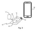
図3は、皮膚領域50に装着された、組み立てられた状態の身体着用可能なCGMシステム10の実施形態を示している。可撓性プリント回路構成14と、離間したインターフェイスまたはディスプレイ構成要素17との間のデータ接続52は、好ましくは導電性織物によって提供される。これにより、衣服の上でディスプレイ17を連続的に見ることができる。さらに、一体化されたアンテナ40を介して、遠隔携帯式データ取得装置56への無線接続54を確立することができ、遠隔携帯式データ取得装置56は、アプリの形態の適合ソフトウェアを装備したスマートフォンとして提供され得る。 FIG. 3 illustrates an embodiment of the body-worn
Claims (16)
Translated fromJapanesei)自己接着型の可撓性電子パッチ(12)をユーザーの皮膚(50)に接着するステップであって、前記自己接着型の可撓性電子パッチ(12)は、前記皮膚(50)の輪郭に追従するように変形可能であり、電子パッチ(12)は、箔基板(16)上に直接適用される可撓性プリント回路構成(14)を含む、ステップと、
ii)ユーザーインターフェイス(17)を使用することにより、前記ユーザーにより装置(10)を制御するステップであって、前記ユーザーインターフェイス(17)は、前記自己接着型の可撓性電子パッチ(12)の一体化された部分である、ステップと
を含む、方法。A method for controlling at least one wearable medical device according to any one of claims 1 to 15, said method comprising: i) a self-adhesive flexible electronic patch: Adhering (12) to the user's skin (50), the self-adhesive flexible electronic patch (12) being deformable to follow the contours of the skin (50), The electronic patch (12) comprises a flexible printed circuit arrangement (14) applied directly onto a foil substrate (16), the steps:
ii) Controlling the device (10) by the user by using the user interface (17), the user interface (17) comprising the self-adhesive flexible electronic patch (12). A step that is an integral part.
Priority Applications (1)
| Application Number | Priority Date | Filing Date | Title |
|---|---|---|---|
| JP2021130927AJP2021180905A (en) | 2017-04-04 | 2021-08-10 | Body-wearable medical device |
Applications Claiming Priority (3)
| Application Number | Priority Date | Filing Date | Title |
|---|---|---|---|
| EP17164839.7 | 2017-04-04 | ||
| EP17164839 | 2017-04-04 | ||
| PCT/EP2018/058566WO2018185138A1 (en) | 2017-04-04 | 2018-04-04 | Body-wearable medical device |
Related Child Applications (1)
| Application Number | Title | Priority Date | Filing Date |
|---|---|---|---|
| JP2021130927ADivisionJP2021180905A (en) | 2017-04-04 | 2021-08-10 | Body-wearable medical device |
Publications (2)
| Publication Number | Publication Date |
|---|---|
| JP2020515353Atrue JP2020515353A (en) | 2020-05-28 |
| JP7113845B2 JP7113845B2 (en) | 2022-08-05 |
Family
ID=58489566
Family Applications (2)
| Application Number | Title | Priority Date | Filing Date |
|---|---|---|---|
| JP2019554660AActiveJP7113845B2 (en) | 2017-04-04 | 2018-04-04 | wearable medical device |
| JP2021130927APendingJP2021180905A (en) | 2017-04-04 | 2021-08-10 | Body-wearable medical device |
Family Applications After (1)
| Application Number | Title | Priority Date | Filing Date |
|---|---|---|---|
| JP2021130927APendingJP2021180905A (en) | 2017-04-04 | 2021-08-10 | Body-wearable medical device |
Country Status (7)
| Country | Link |
|---|---|
| US (1) | US20200029902A1 (en) |
| EP (1) | EP3606426A1 (en) |
| JP (2) | JP7113845B2 (en) |
| CN (1) | CN110461232A (en) |
| CA (1) | CA3053362C (en) |
| RU (1) | RU2745731C1 (en) |
| WO (1) | WO2018185138A1 (en) |
Families Citing this family (57)
| Publication number | Priority date | Publication date | Assignee | Title |
|---|---|---|---|---|
| CA3022184A1 (en) | 2016-04-26 | 2017-11-02 | Smith & Nephew Plc | Wound dressings and methods of use with integrated negative pressure source having a fluid ingress inhibition component |
| WO2017191158A1 (en) | 2016-05-03 | 2017-11-09 | Smith & Nephew Plc | Systems and methods for driving negative pressure sources in negative pressure therapy systems |
| US11096831B2 (en) | 2016-05-03 | 2021-08-24 | Smith & Nephew Plc | Negative pressure wound therapy device activation and control |
| CA3038206A1 (en) | 2016-05-03 | 2017-11-09 | Smith & Nephew Plc | Optimizing power transfer to negative pressure sources in negative pressure therapy systems |
| CA3023772A1 (en) | 2016-05-13 | 2017-11-16 | Smith & Nephew Plc | Sensor enabled wound monitoring and therapy apparatus |
| WO2018037075A1 (en) | 2016-08-25 | 2018-03-01 | Smith & Nephew Plc | Absorbent negative pressure wound therapy dressing |
| EP3519001B1 (en) | 2016-09-30 | 2025-05-21 | Smith & Nephew plc | Negative pressure wound treatment apparatuses and methods with integrated electronics |
| EP3551244A1 (en) | 2016-12-12 | 2019-10-16 | Smith & Nephew PLC | Pressure wound therapy status indication via external device |
| EP3592312B1 (en) | 2017-03-08 | 2024-01-10 | Smith & Nephew plc | Negative pressure wound therapy device control in presence of fault condition |
| EP3592230A1 (en) | 2017-03-09 | 2020-01-15 | Smith & Nephew PLC | Apparatus and method for imaging blood in a target region of tissue |
| JP7091356B2 (en) | 2017-03-09 | 2022-06-27 | スミス アンド ネフュー ピーエルシー | Devices, devices, and methods for determining skin perfusion pressure |
| US11690570B2 (en) | 2017-03-09 | 2023-07-04 | Smith & Nephew Plc | Wound dressing, patch member and method of sensing one or more wound parameters |
| CA3059516A1 (en) | 2017-04-11 | 2018-10-18 | Smith & Nephew Plc | Component positioning and stress relief for sensor enabled wound dressings |
| JP7121050B2 (en) | 2017-05-09 | 2022-08-17 | スミス アンド ネフュー ピーエルシー | Redundant control of negative pressure wound therapy systems |
| EP3635733A1 (en) | 2017-05-15 | 2020-04-15 | Smith & Nephew plc | Negative pressure wound therapy system using eulerian video magnification |
| AU2018269112B2 (en) | 2017-05-15 | 2024-05-02 | Smith & Nephew Plc | Wound analysis device and method |
| JP7189159B2 (en) | 2017-06-23 | 2022-12-13 | スミス アンド ネフュー ピーエルシー | Sensor placement for sensor-enabled wound monitoring or therapy |
| GB201809007D0 (en) | 2018-06-01 | 2018-07-18 | Smith & Nephew | Restriction of sensor-monitored region for sensor-enabled wound dressings |
| GB201804502D0 (en) | 2018-03-21 | 2018-05-02 | Smith & Nephew | Biocompatible encapsulation and component stress relief for sensor enabled negative pressure wound therapy dressings |
| SG11202000913XA (en) | 2017-08-10 | 2020-02-27 | Smith & Nephew | Positioning of sensors for sensor enabled wound monitoring or therapy |
| GB201718870D0 (en) | 2017-11-15 | 2017-12-27 | Smith & Nephew Inc | Sensor enabled wound therapy dressings and systems |
| GB201804971D0 (en) | 2018-03-28 | 2018-05-09 | Smith & Nephew | Electrostatic discharge protection for sensors in wound therapy |
| CN111093477B (en) | 2017-09-10 | 2023-09-12 | 史密夫及内修公开有限公司 | Systems and methods for inspecting packages and components in sensor-equipped wound dressings |
| CA3074780A1 (en) | 2017-09-13 | 2019-03-21 | Smith & Nephew Plc | Negative pressure wound treatment apparatuses and methods with integrated electronics |
| GB201718070D0 (en) | 2017-11-01 | 2017-12-13 | Smith & Nephew | Negative pressure wound treatment apparatuses and methods with integrated electronics |
| GB201718859D0 (en) | 2017-11-15 | 2017-12-27 | Smith & Nephew | Sensor positioning for sensor enabled wound therapy dressings and systems |
| WO2019063481A1 (en) | 2017-09-27 | 2019-04-04 | Smith & Nephew Plc | Ph sensing for sensor enabled negative pressure wound monitoring and therapy apparatuses |
| WO2019072531A1 (en) | 2017-09-28 | 2019-04-18 | Smith & Nephew Plc | Neurostimulation and monitoring using sensor enabled wound monitoring and therapy apparatus |
| GB201718054D0 (en) | 2017-11-01 | 2017-12-13 | Smith & Nephew | Sterilization of integrated negative pressure wound treatment apparatuses and sterilization methods |
| US11497653B2 (en) | 2017-11-01 | 2022-11-15 | Smith & Nephew Plc | Negative pressure wound treatment apparatuses and methods with integrated electronics |
| GB201718072D0 (en) | 2017-11-01 | 2017-12-13 | Smith & Nephew | Negative pressure wound treatment apparatuses and methods with integrated electronics |
| US11559438B2 (en) | 2017-11-15 | 2023-01-24 | Smith & Nephew Plc | Integrated sensor enabled wound monitoring and/or therapy dressings and systems |
| US11251635B2 (en)* | 2017-12-19 | 2022-02-15 | Welch Allyn, Inc. | Vital signs monitor with a removable and dischargable battery |
| GB201814011D0 (en) | 2018-08-29 | 2018-10-10 | Smith & Nephew | Componet positioning and encapsulation for sensor enabled wound dressings |
| EP3849401A1 (en) | 2018-09-12 | 2021-07-21 | Smith & Nephew plc | Device, apparatus and method of determining skin perfusion pressure |
| USD898925S1 (en) | 2018-09-13 | 2020-10-13 | Smith & Nephew Plc | Medical dressing |
| WO2020064937A1 (en) | 2018-09-28 | 2020-04-02 | T.J.Smith And Nephew,Limited | Optical fibers for optically sensing through wound dressings |
| GB201816838D0 (en) | 2018-10-16 | 2018-11-28 | Smith & Nephew | Systems and method for applying biocompatible encapsulation to sensor enabled wound monitoring and therapy dressings |
| KR102425542B1 (en) | 2018-10-30 | 2022-07-26 | 주식회사 케이티앤지 | Disposable liquid type aerosol-generating device and device comprising theh same |
| GB201820927D0 (en) | 2018-12-21 | 2019-02-06 | Smith & Nephew | Wound therapy systems and methods with supercapacitors |
| JP7529681B2 (en) | 2019-03-18 | 2024-08-06 | スミス アンド ネフュー ピーエルシー | Design rules for sensor integrated boards |
| GB201903774D0 (en) | 2019-03-20 | 2019-05-01 | Smith & Nephew | Negative pressure wound treatment apparatuses and methods with integrated electronics |
| GB201907716D0 (en) | 2019-05-31 | 2019-07-17 | Smith & Nephew | Systems and methods for extending operational time of negative pressure wound treatment apparatuses |
| GB201914443D0 (en) | 2019-10-07 | 2019-11-20 | Smith & Nephew | Sensor enabled negative pressure wound monitoring apparatus with different impedances inks |
| WO2021076940A1 (en)* | 2019-10-16 | 2021-04-22 | Balman James Robert | Apparatus and method for determining physiological parameters of an infant in-utero |
| KR20210116007A (en)* | 2020-03-17 | 2021-09-27 | 엘지이노텍 주식회사 | Sensing device |
| EP4139904A1 (en) | 2020-04-21 | 2023-03-01 | T.J. Smith and Nephew, Limited | Wound treatment management using augmented reality overlay |
| CN111904395B (en)* | 2020-07-24 | 2022-04-01 | 厦门大学 | Flexible base material for physiological information sensing and manufacturing method thereof |
| US20220126017A1 (en)* | 2020-10-23 | 2022-04-28 | Insulet Corporation | Body conforming wearable device for providing output and input for a drug delivery system |
| CN115684597A (en)* | 2021-07-31 | 2023-02-03 | 华为技术有限公司 | Monitoring device and monitoring equipment |
| WO2023044889A1 (en)* | 2021-09-27 | 2023-03-30 | Medtrum Technologies Inc. | Analyte detection system |
| CN116236192A (en)* | 2021-12-07 | 2023-06-09 | 上海微创生命科技有限公司 | Continuous blood glucose monitoring device and continuous blood glucose monitoring system |
| EP4201326A1 (en)* | 2021-12-22 | 2023-06-28 | F. Hoffmann-La Roche AG | Body wearable analyte sensor system with noncontact temperature sensor |
| CN118647314A (en)* | 2022-02-04 | 2024-09-13 | 雅培糖尿病护理公司 | Systems, devices and methods for analyte sensors |
| WO2025014515A1 (en) | 2023-07-10 | 2025-01-16 | Roche Diabetes Care, Inc. | Sensor connector |
| KR20250068026A (en)* | 2023-11-08 | 2025-05-16 | 한국전자기술연구원 | A patch-type biosignal collection device |
| US12340264B1 (en) | 2024-03-20 | 2025-06-24 | Qualcomm Incorporated | Battery antenna for smart label |
Citations (9)
| Publication number | Priority date | Publication date | Assignee | Title |
|---|---|---|---|---|
| JP2008532596A (en)* | 2005-03-09 | 2008-08-21 | クティセンセ アクティーゼルスカブ | Three-dimensional adhesive device with embedded microelectronic system |
| JP2009509166A (en)* | 2005-09-23 | 2009-03-05 | メドトロニック・ミニメッド・インコーポレーテッド | Detector with layered electrode |
| US20100324392A1 (en)* | 2009-02-03 | 2010-12-23 | Phillip Yee | Analyte sensor and apparatus for insertion of the sensor |
| JP2010540181A (en)* | 2007-10-02 | 2010-12-24 | メドトロニック ミニメド インコーポレイテッド | Glucose sensor transceiver |
| JP2011125677A (en)* | 2009-11-17 | 2011-06-30 | Fujikura Ltd | Arm cover of artificial arm for measuring myogenic potential |
| JP2012002804A (en)* | 2010-05-19 | 2012-01-05 | Arkray Inc | Electrochemical sensor |
| US20140273042A1 (en)* | 2013-03-15 | 2014-09-18 | Tandem Diabetes Care, Inc. | Predictive calibration |
| JP2016539698A (en)* | 2013-11-29 | 2016-12-22 | エムシー10 インコーポレイテッドMc10,Inc. | Systems, methods and devices having stretchable integrated circuits for sensing and therapy delivery |
| WO2017003857A1 (en)* | 2015-07-02 | 2017-01-05 | Verily Life Sciences Llc | Calibration methods for bandage-type analyte sensor |
Family Cites Families (16)
| Publication number | Priority date | Publication date | Assignee | Title |
|---|---|---|---|---|
| US9259175B2 (en) | 2006-10-23 | 2016-02-16 | Abbott Diabetes Care, Inc. | Flexible patch for fluid delivery and monitoring body analytes |
| US8214007B2 (en)* | 2006-11-01 | 2012-07-03 | Welch Allyn, Inc. | Body worn physiological sensor device having a disposable electrode module |
| US8845530B2 (en) | 2007-01-02 | 2014-09-30 | Isense Corporation | Resposable biosensor assembly and method of sensing |
| AU2009303835A1 (en)* | 2008-10-16 | 2010-04-22 | Naresh Chandra Bhavaraju | Method and devices for self adjusting phototherapeutic intervention |
| EP3001194B1 (en)* | 2009-08-31 | 2019-04-17 | Abbott Diabetes Care, Inc. | Medical devices and methods |
| DK2563450T3 (en)* | 2010-04-28 | 2017-11-13 | Kimberly Clark Co | Apparatus for administering rheumatoid arthritis drug |
| CN104219999A (en)* | 2012-01-30 | 2014-12-17 | 感官系统公司 | Sensors, interfaces and sensor systems for data collection and integrated remote monitoring of conditions at or near body surfaces |
| JP6250571B2 (en) | 2012-03-12 | 2017-12-20 | スミス アンド ネフュー ピーエルシーSmith & Nephew Public Limited Company | Pressure reducing apparatus and method |
| KR20150139865A (en) | 2013-03-15 | 2015-12-14 | 잔소르스 엘엘씨 | Health monitoring, surveillance and anomaly detection |
| WO2014185426A1 (en)* | 2013-05-13 | 2014-11-20 | 国立大学法人名古屋大学 | Non-volatile photonic material, and production method thereof |
| EP3122248A4 (en)* | 2014-03-28 | 2018-05-02 | Board of Regents, The University of Texas System | Epidermal sensor system and process |
| US10722160B2 (en)* | 2014-12-03 | 2020-07-28 | The Regents Of The University Of California | Non-invasive and wearable chemical sensors and biosensors |
| US20160338646A1 (en)* | 2015-05-20 | 2016-11-24 | Mc10, Inc. | Ultra-thin wearable sensing device |
| US10105100B2 (en)* | 2015-07-28 | 2018-10-23 | Verily Life Sciences Llc | Display on a bandage-type monitoring device |
| CN205581939U (en)* | 2016-04-12 | 2016-09-14 | 苏州纳格光电科技有限公司 | Flexible wearable device |
| US20160310049A1 (en) | 2016-06-30 | 2016-10-27 | Fitbit, Inc. | Wearable devices incorporating ion selective field effect transistors |
- 2018
- 2018-04-04CNCN201880021427.6Apatent/CN110461232A/enactivePending
- 2018-04-04RURU2019134224Apatent/RU2745731C1/enactive
- 2018-04-04JPJP2019554660Apatent/JP7113845B2/enactiveActive
- 2018-04-04EPEP18714529.7Apatent/EP3606426A1/enactivePending
- 2018-04-04WOPCT/EP2018/058566patent/WO2018185138A1/ennot_activeCeased
- 2018-04-04CACA3053362Apatent/CA3053362C/enactiveActive
- 2019
- 2019-10-01USUS16/589,966patent/US20200029902A1/ennot_activeAbandoned
- 2021
- 2021-08-10JPJP2021130927Apatent/JP2021180905A/enactivePending
Patent Citations (9)
| Publication number | Priority date | Publication date | Assignee | Title |
|---|---|---|---|---|
| JP2008532596A (en)* | 2005-03-09 | 2008-08-21 | クティセンセ アクティーゼルスカブ | Three-dimensional adhesive device with embedded microelectronic system |
| JP2009509166A (en)* | 2005-09-23 | 2009-03-05 | メドトロニック・ミニメッド・インコーポレーテッド | Detector with layered electrode |
| JP2010540181A (en)* | 2007-10-02 | 2010-12-24 | メドトロニック ミニメド インコーポレイテッド | Glucose sensor transceiver |
| US20100324392A1 (en)* | 2009-02-03 | 2010-12-23 | Phillip Yee | Analyte sensor and apparatus for insertion of the sensor |
| JP2011125677A (en)* | 2009-11-17 | 2011-06-30 | Fujikura Ltd | Arm cover of artificial arm for measuring myogenic potential |
| JP2012002804A (en)* | 2010-05-19 | 2012-01-05 | Arkray Inc | Electrochemical sensor |
| US20140273042A1 (en)* | 2013-03-15 | 2014-09-18 | Tandem Diabetes Care, Inc. | Predictive calibration |
| JP2016539698A (en)* | 2013-11-29 | 2016-12-22 | エムシー10 インコーポレイテッドMc10,Inc. | Systems, methods and devices having stretchable integrated circuits for sensing and therapy delivery |
| WO2017003857A1 (en)* | 2015-07-02 | 2017-01-05 | Verily Life Sciences Llc | Calibration methods for bandage-type analyte sensor |
Also Published As
| Publication number | Publication date |
|---|---|
| RU2745731C1 (en) | 2021-03-31 |
| CN110461232A (en) | 2019-11-15 |
| US20200029902A1 (en) | 2020-01-30 |
| CA3053362A1 (en) | 2018-10-11 |
| JP7113845B2 (en) | 2022-08-05 |
| EP3606426A1 (en) | 2020-02-12 |
| CA3053362C (en) | 2022-11-29 |
| JP2021180905A (en) | 2021-11-25 |
| WO2018185138A1 (en) | 2018-10-11 |
Similar Documents
| Publication | Publication Date | Title |
|---|---|---|
| JP7113845B2 (en) | wearable medical device | |
| US11259725B2 (en) | Interconnect for on-body analyte monitoring device | |
| CN110621227B (en) | Sensor system and method for producing the same | |
| US9757049B2 (en) | Electrode and device for detecting biosignal and method of using the same | |
| JP4921349B2 (en) | Wearable wireless device for monitoring, analysis and transmission of physiological conditions | |
| US8688189B2 (en) | Programmable ECG sensor patch | |
| JP7483081B2 (en) | Medical sensor system, particularly a continuous glucose monitoring system | |
| WO2008005015A1 (en) | Programmable ecg sensor patch | |
| WO2017040593A1 (en) | Wireless medical evaluation device | |
| US20200054258A1 (en) | Medical system | |
| HK40017838A (en) | Body-wearable medical device | |
| WO2024165947A1 (en) | Flexible, elastic and sensor-equipped adhesive device for the remote monitoring of the physiological parameters of a patient | |
| HK40017210A (en) | Medical sensor system, in particular continuous glucose monitoring system | |
| HK40020012A (en) | Sensor system and method for manufacturing thereof | |
| HK40020012B (en) | Sensor system and method for manufacturing thereof |
Legal Events
| Date | Code | Title | Description |
|---|---|---|---|
| A521 | Request for written amendment filed | Free format text:JAPANESE INTERMEDIATE CODE: A523 Effective date:20191106 | |
| A621 | Written request for application examination | Free format text:JAPANESE INTERMEDIATE CODE: A621 Effective date:20191106 | |
| A977 | Report on retrieval | Free format text:JAPANESE INTERMEDIATE CODE: A971007 Effective date:20201008 | |
| A131 | Notification of reasons for refusal | Free format text:JAPANESE INTERMEDIATE CODE: A131 Effective date:20201110 | |
| A521 | Request for written amendment filed | Free format text:JAPANESE INTERMEDIATE CODE: A523 Effective date:20210203 | |
| A02 | Decision of refusal | Free format text:JAPANESE INTERMEDIATE CODE: A02 Effective date:20210413 | |
| A521 | Request for written amendment filed | Free format text:JAPANESE INTERMEDIATE CODE: A523 Effective date:20210810 | |
| C60 | Trial request (containing other claim documents, opposition documents) | Free format text:JAPANESE INTERMEDIATE CODE: C60 Effective date:20210810 | |
| A911 | Transfer to examiner for re-examination before appeal (zenchi) | Free format text:JAPANESE INTERMEDIATE CODE: A911 Effective date:20210819 | |
| C21 | Notice of transfer of a case for reconsideration by examiners before appeal proceedings | Free format text:JAPANESE INTERMEDIATE CODE: C21 Effective date:20210824 | |
| A912 | Re-examination (zenchi) completed and case transferred to appeal board | Free format text:JAPANESE INTERMEDIATE CODE: A912 Effective date:20210910 | |
| C211 | Notice of termination of reconsideration by examiners before appeal proceedings | Free format text:JAPANESE INTERMEDIATE CODE: C211 Effective date:20210914 | |
| C22 | Notice of designation (change) of administrative judge | Free format text:JAPANESE INTERMEDIATE CODE: C22 Effective date:20210928 | |
| C13 | Notice of reasons for refusal | Free format text:JAPANESE INTERMEDIATE CODE: C13 Effective date:20220104 | |
| A521 | Request for written amendment filed | Free format text:JAPANESE INTERMEDIATE CODE: A523 Effective date:20220308 | |
| C22 | Notice of designation (change) of administrative judge | Free format text:JAPANESE INTERMEDIATE CODE: C22 Effective date:20220412 | |
| C23 | Notice of termination of proceedings | Free format text:JAPANESE INTERMEDIATE CODE: C23 Effective date:20220531 | |
| C03 | Trial/appeal decision taken | Free format text:JAPANESE INTERMEDIATE CODE: C03 Effective date:20220628 | |
| C30A | Notification sent | Free format text:JAPANESE INTERMEDIATE CODE: C3012 Effective date:20220628 | |
| A61 | First payment of annual fees (during grant procedure) | Free format text:JAPANESE INTERMEDIATE CODE: A61 Effective date:20220726 | |
| R150 | Certificate of patent or registration of utility model | Ref document number:7113845 Country of ref document:JP Free format text:JAPANESE INTERMEDIATE CODE: R150 | |
| R250 | Receipt of annual fees | Free format text:JAPANESE INTERMEDIATE CODE: R250 |