JP2020509856A - Surgical fixation systems - Google Patents
Surgical fixation systemsDownload PDFInfo
- Publication number
- JP2020509856A JP2020509856AJP2019549572AJP2019549572AJP2020509856AJP 2020509856 AJP2020509856 AJP 2020509856AJP 2019549572 AJP2019549572 AJP 2019549572AJP 2019549572 AJP2019549572 AJP 2019549572AJP 2020509856 AJP2020509856 AJP 2020509856A
- Authority
- JP
- Japan
- Prior art keywords
- loop
- aperture
- adjustable
- fixation device
- strand
- Prior art date
- Legal status (The legal status is an assumption and is not a legal conclusion. Google has not performed a legal analysis and makes no representation as to the accuracy of the status listed.)
- Granted
Links
Images


Classifications
- A—HUMAN NECESSITIES
- A61—MEDICAL OR VETERINARY SCIENCE; HYGIENE
- A61B—DIAGNOSIS; SURGERY; IDENTIFICATION
- A61B17/00—Surgical instruments, devices or methods
- A61B17/04—Surgical instruments, devices or methods for suturing wounds; Holders or packages for needles or suture materials
- A61B17/0401—Suture anchors, buttons or pledgets, i.e. means for attaching sutures to bone, cartilage or soft tissue; Instruments for applying or removing suture anchors
- A—HUMAN NECESSITIES
- A61—MEDICAL OR VETERINARY SCIENCE; HYGIENE
- A61F—FILTERS IMPLANTABLE INTO BLOOD VESSELS; PROSTHESES; DEVICES PROVIDING PATENCY TO, OR PREVENTING COLLAPSING OF, TUBULAR STRUCTURES OF THE BODY, e.g. STENTS; ORTHOPAEDIC, NURSING OR CONTRACEPTIVE DEVICES; FOMENTATION; TREATMENT OR PROTECTION OF EYES OR EARS; BANDAGES, DRESSINGS OR ABSORBENT PADS; FIRST-AID KITS
- A61F2/00—Filters implantable into blood vessels; Prostheses, i.e. artificial substitutes or replacements for parts of the body; Appliances for connecting them with the body; Devices providing patency to, or preventing collapsing of, tubular structures of the body, e.g. stents
- A61F2/02—Prostheses implantable into the body
- A61F2/08—Muscles; Tendons; Ligaments
- A61F2/0811—Fixation devices for tendons or ligaments
- A—HUMAN NECESSITIES
- A61—MEDICAL OR VETERINARY SCIENCE; HYGIENE
- A61B—DIAGNOSIS; SURGERY; IDENTIFICATION
- A61B17/00—Surgical instruments, devices or methods
- A61B17/04—Surgical instruments, devices or methods for suturing wounds; Holders or packages for needles or suture materials
- A61B17/0401—Suture anchors, buttons or pledgets, i.e. means for attaching sutures to bone, cartilage or soft tissue; Instruments for applying or removing suture anchors
- A61B2017/0404—Buttons
- A—HUMAN NECESSITIES
- A61—MEDICAL OR VETERINARY SCIENCE; HYGIENE
- A61F—FILTERS IMPLANTABLE INTO BLOOD VESSELS; PROSTHESES; DEVICES PROVIDING PATENCY TO, OR PREVENTING COLLAPSING OF, TUBULAR STRUCTURES OF THE BODY, e.g. STENTS; ORTHOPAEDIC, NURSING OR CONTRACEPTIVE DEVICES; FOMENTATION; TREATMENT OR PROTECTION OF EYES OR EARS; BANDAGES, DRESSINGS OR ABSORBENT PADS; FIRST-AID KITS
- A61F2/00—Filters implantable into blood vessels; Prostheses, i.e. artificial substitutes or replacements for parts of the body; Appliances for connecting them with the body; Devices providing patency to, or preventing collapsing of, tubular structures of the body, e.g. stents
- A61F2/02—Prostheses implantable into the body
- A61F2/08—Muscles; Tendons; Ligaments
- A61F2/0811—Fixation devices for tendons or ligaments
- A61F2002/0847—Mode of fixation of anchor to tendon or ligament
- A61F2002/0852—Fixation of a loop or U-turn, e.g. eyelets, anchor having multiple holes
- A—HUMAN NECESSITIES
- A61—MEDICAL OR VETERINARY SCIENCE; HYGIENE
- A61F—FILTERS IMPLANTABLE INTO BLOOD VESSELS; PROSTHESES; DEVICES PROVIDING PATENCY TO, OR PREVENTING COLLAPSING OF, TUBULAR STRUCTURES OF THE BODY, e.g. STENTS; ORTHOPAEDIC, NURSING OR CONTRACEPTIVE DEVICES; FOMENTATION; TREATMENT OR PROTECTION OF EYES OR EARS; BANDAGES, DRESSINGS OR ABSORBENT PADS; FIRST-AID KITS
- A61F2/00—Filters implantable into blood vessels; Prostheses, i.e. artificial substitutes or replacements for parts of the body; Appliances for connecting them with the body; Devices providing patency to, or preventing collapsing of, tubular structures of the body, e.g. stents
- A61F2/02—Prostheses implantable into the body
- A61F2/08—Muscles; Tendons; Ligaments
- A61F2/0811—Fixation devices for tendons or ligaments
- A61F2002/0847—Mode of fixation of anchor to tendon or ligament
- A61F2002/0858—Fixation of tendon or ligament between anchor and bone, e.g. interference screws, wedges
- A—HUMAN NECESSITIES
- A61—MEDICAL OR VETERINARY SCIENCE; HYGIENE
- A61F—FILTERS IMPLANTABLE INTO BLOOD VESSELS; PROSTHESES; DEVICES PROVIDING PATENCY TO, OR PREVENTING COLLAPSING OF, TUBULAR STRUCTURES OF THE BODY, e.g. STENTS; ORTHOPAEDIC, NURSING OR CONTRACEPTIVE DEVICES; FOMENTATION; TREATMENT OR PROTECTION OF EYES OR EARS; BANDAGES, DRESSINGS OR ABSORBENT PADS; FIRST-AID KITS
- A61F2/00—Filters implantable into blood vessels; Prostheses, i.e. artificial substitutes or replacements for parts of the body; Appliances for connecting them with the body; Devices providing patency to, or preventing collapsing of, tubular structures of the body, e.g. stents
- A61F2/02—Prostheses implantable into the body
- A61F2/08—Muscles; Tendons; Ligaments
- A61F2/0811—Fixation devices for tendons or ligaments
- A61F2002/0876—Position of anchor in respect to the bone
- A61F2002/0882—Anchor in or on top of a bone tunnel, i.e. a hole running through the entire bone
- A—HUMAN NECESSITIES
- A61—MEDICAL OR VETERINARY SCIENCE; HYGIENE
- A61F—FILTERS IMPLANTABLE INTO BLOOD VESSELS; PROSTHESES; DEVICES PROVIDING PATENCY TO, OR PREVENTING COLLAPSING OF, TUBULAR STRUCTURES OF THE BODY, e.g. STENTS; ORTHOPAEDIC, NURSING OR CONTRACEPTIVE DEVICES; FOMENTATION; TREATMENT OR PROTECTION OF EYES OR EARS; BANDAGES, DRESSINGS OR ABSORBENT PADS; FIRST-AID KITS
- A61F2/00—Filters implantable into blood vessels; Prostheses, i.e. artificial substitutes or replacements for parts of the body; Appliances for connecting them with the body; Devices providing patency to, or preventing collapsing of, tubular structures of the body, e.g. stents
- A61F2/02—Prostheses implantable into the body
- A61F2/28—Bones
- A61F2002/2835—Bone graft implants for filling a bony defect or an endoprosthesis cavity, e.g. by synthetic material or biological material
Landscapes
- Health & Medical Sciences (AREA)
- Life Sciences & Earth Sciences (AREA)
- Surgery (AREA)
- Animal Behavior & Ethology (AREA)
- General Health & Medical Sciences (AREA)
- Engineering & Computer Science (AREA)
- Biomedical Technology (AREA)
- Heart & Thoracic Surgery (AREA)
- Veterinary Medicine (AREA)
- Public Health (AREA)
- Rheumatology (AREA)
- Medical Informatics (AREA)
- Molecular Biology (AREA)
- Nuclear Medicine, Radiotherapy & Molecular Imaging (AREA)
- Orthopedic Medicine & Surgery (AREA)
- Rehabilitation Therapy (AREA)
- Cardiology (AREA)
- Oral & Maxillofacial Surgery (AREA)
- Transplantation (AREA)
- Vascular Medicine (AREA)
- Surgical Instruments (AREA)
Abstract
Translated fromJapaneseDescription
Translated fromJapanese本開示は、骨トンネル内に移植片又はフィラメントを固定する外科的固定のシステム及び方法に関する。 The present disclosure relates to systems and methods for surgical fixation of a graft or filament in a bone tunnel.
関連出願の相互参照
本願は、2017年3月13日に出願された米国仮出願第62/470,522号の優先権を主張し、その全体が参照によりここに組み入れられる。CROSS-REFERENCE TO RELATED APPLICATIONS This application claims priority to US Provisional Application No. 62 / 470,522, filed March 13, 2017, which is hereby incorporated by reference in its entirety.
前十字靭帯(ACL)再建及び後十字靭帯(PCL)再建のような組織再建手術は典型的に、骨にトンネルを通すドリリングをすることと、その骨トンネルの中に代用移植片を配置することと、その移植片を骨トンネル内に、ボタン、ねじ等の固定デバイスを使用して固定することとを含む。 Tissue reconstruction procedures such as anterior cruciate ligament (ACL) reconstruction and posterior cruciate ligament (PCL) reconstruction typically involve drilling a bone through a tunnel and placing a substitute implant in the bone tunnel. And securing the implant in the bone tunnel using a fixation device such as a button, screw or the like.
本開示は、外科的固定のシステム及び方法に関する。外科的固定のシステムは、固定デバイスと、当該固定デバイスに接続されたループとを含み得る。移植片は、ループによって担持することができる。外科的固定のシステムは、ACL再建及びPCL再建を含むがこれらに限られない様々な組織再建処置において使用することができる。 The present disclosure relates to systems and methods for surgical fixation. A surgical fixation system may include a fixation device and a loop connected to the fixation device. The implant can be carried by the loop. The surgical fixation system can be used in various tissue reconstruction procedures, including but not limited to ACL reconstruction and PCL reconstruction.
本開示の典型的側面に係る外科的固定のシステムは、とりわけ、固定デバイスと、当該固定デバイスに接続された調整可能ループとを含み得る。調整可能ループは、第1調整可能アイスプライスループを含み、これは、第2調整可能アイスプライスループを通過し、固定デバイスのブリッジの上に載置される相互接続部において第2調整可能アイスプライスループと相互連結する。 A surgical fixation system according to an exemplary aspect of the present disclosure may include, inter alia, a fixation device and an adjustable loop connected to the fixation device. The adjustable loop includes a first adjustable ice price loop that passes through the second adjustable ice price loop and a second adjustable ice price at an interconnect mounted on a bridge of the securing device. Interconnect with the loop.
外科的固定のシステムの固定デバイスはボタンとしてよい。 The fixation device of the surgical fixation system may be a button.
ブリッジは、固定デバイスの第1アパチャと第2アパチャとの間に配置することができる。 The bridge may be located between the first aperture and the second aperture of the fixation device.
システムはさらに、固定デバイスの、通過フィラメントを担持し得る第3アパチャを含む。 The system further includes a third aperture of the fixation device that can carry the passing filament.
第1調整可能アイスプライスループは、固定デバイスの第1アパチャを通して受容され得る。第2調整可能アイスプライスループは、固定デバイスの第2アパチャを通して受容され得る。 A first adjustable ice price loop may be received through a first aperture of the fixation device. A second adjustable ice price loop may be received through a second aperture of the fixation device.
調整可能ループは、第1調整可能アイスプライスループを調整するための第1自由編みストランドを含み得る。調整可能ループは、第2調整可能アイスプライスループを調整するための第2自由編みストランドを含み得る。 The adjustable loop may include a first free-knit strand for adjusting the first adjustable ice price loop. The adjustable loop may include a second free knitting strand for adjusting a second adjustable ice price loop.
第1自由編みストランドは第2調整可能アイスプライスループを通過し、第2自由編みストランドは第1調整可能アイスプライスループを通過してよい。第1自由編みストランドは、第2調整可能アイスプライスループを通過するべく固定デバイスの第1開口を通過することができる。第2自由編みストランドは、第1調整可能アイスプライスループを通過するべく固定デバイスの第2開口を通過することができる。 The first free knitting strand may pass through the second adjustable ice price loop and the second free knitting strand may pass through the first adjustable ice price loop. The first free knitting strand can pass through a first opening of the fixation device to pass through a second adjustable ice price loop. The second free knitting strand can pass through a second opening of the fixation device to pass through the first adjustable ice price loop.
第1自由編みストランド及び/又は第2自由編みストランドはそれぞれが、少なくとも2回、調整可能ループを通るように組み継ぎされる。 The first free knitting strand and / or the second free knitting strand are each spliced at least twice through the adjustable loop.
固定デバイスは、頂面及び底面を含み得る。ブリッジには、頂面から皿穴を開けてよい。 The fixation device may include a top surface and a bottom surface. The bridge may be countersunk from the top.
第1調整可能アイスプライスループ、第2調整可能アイスプライスループ、及び調整可能ループの自由編みストランドは、協働して、当該調整可能ループと固定デバイスとの接合部に結び目スタックを確立することができる。 The first adjustable ice price loop, the second adjustable ice price loop, and the free knitting strand of the adjustable loop can cooperate to establish a knot stack at the junction of the adjustable loop and the fixation device. it can.
結び目スタックは、固定デバイスのブリッジの上に載置され得る。 The knot stack may rest on the bridge of the anchoring device.
外科的固定のシステムは、固定デバイスと調整可能ループとの接合部に結び目スタックを含み得る。 Surgical fixation systems may include a knot stack at the junction of the fixation device and the adjustable loop.
結び目スタックは、少なくとも2つの調整可能アイスプライスループと、当該少なくとも2つの調整可能アイスプライスループを形成するべく使用された可撓性ストランドの自由編みストランドとによって確立することができる。 The knot stack can be established by at least two adjustable ice-price loops and free-knit strands of flexible strands used to form the at least two adjustable ice-price loops.
本開示の他の典型的側面に係る外科的方法は、とりわけ、固定デバイスと当該固定デバイスに接続された調整可能ループとを含む外科的固定のシステムを使用して骨トンネルの中に移植片を固定することを含む。調整可能ループは、固定デバイスと調整可能ループとの接合部に配置された相互接続部において相互連結された少なくとも2つの調整可能アイスプライスループを含む。 Surgical methods according to other exemplary aspects of the present disclosure include, among other things, a method of implanting an implant into a bone tunnel using a system of surgical fixation that includes a fixation device and an adjustable loop connected to the fixation device. Including fixing. The adjustable loop includes at least two adjustable ice price loops interconnected at an interconnect located at the junction of the fixation device and the adjustable loop.
本開示の他の典型的側面に係る外科的固定のシステムは、とりわけ、固定デバイスと、当該固定デバイスに接続された調整可能ループとを含み得る。固定デバイスは、中心長手軸に沿って延びる本体を含み、頂面及び底面を含んでよい。少なくとも一つのアパチャと、一の縫合糸戻りアパチャとがそれぞれ、本体を通って延び得る。例えば、第1アパチャ及び第2アパチャそれぞれが、本体を通って延び得る。ブリッジは、第1アパチャと第2アパチャとの間に延び得る。調整可能ループは、少なくとも一つのアパチャに接続され得る。例えば、調整可能ループを、第1アパチャ及び第2アパチャに接続することができる。第1自由編みストランドは、調整可能ループの第1組み継ぎセクションから延び、第2自由編みストランドは、当該調整可能ループの第2組み継ぎセクションから延び得る。第1自由編みストランド及び第2自由編みストランドは、縫合糸戻りアパチャを通って延びた後、ブリッジの上に載置された調整可能ループのループセクションの下を延びる。そのループセクションは、ブリッジの上に載置され、外科的固定のシステムのロック機構を確立する。ロック機構のロック位置において、第1自由編みストランド及び第2自由編みストランドは、調整可能ループのループセクションにより、ブリッジの外表面に当接するように張力を受け得る。 A surgical fixation system according to another exemplary aspect of the present disclosure may include, inter alia, a fixation device and an adjustable loop connected to the fixation device. The fixation device includes a body that extends along a central longitudinal axis and may include a top surface and a bottom surface. At least one aperture and one suture return aperture may each extend through the body. For example, each of the first and second apertures may extend through the body. The bridge may extend between the first aperture and the second aperture. The adjustable loop may be connected to at least one aperture. For example, an adjustable loop can be connected to the first aperture and the second aperture. A first free knitting strand may extend from a first splice section of the adjustable loop and a second free knitting strand may extend from a second splice section of the adjustable loop. The first free knitting strand and the second free knitting strand extend under the loop section of the adjustable loop resting on the bridge after extending through the suture return aperture. The loop section rests on the bridge and establishes the locking mechanism of the surgical fixation system. In the locked position of the locking mechanism, the first free knitting strand and the second free knitting strand may be tensioned by the loop section of the adjustable loop to abut the outer surface of the bridge.
ブリッジの外表面は、固定デバイスの頂面と面一としてよい。 The outer surface of the bridge may be flush with the top surface of the fixation device.
外科的固定のシステムはさらに、ブリッジの外表面を通って延びる長手軸を含んでよい。長手軸は、中心長手軸に垂直としてよい。 The surgical fixation system may further include a longitudinal axis extending through the outer surface of the bridge. The longitudinal axis may be perpendicular to the central longitudinal axis.
固定デバイスの第1アパチャ及び第2アパチャは軸方向に整列され、中心長手軸に沿って配置され得る。縫合糸戻りアパチャは、中心長手軸から、本体の側壁に向かう方向にずらされる。 The first aperture and the second aperture of the fixation device may be axially aligned and arranged along a central longitudinal axis. The suture return aperture is offset from the central longitudinal axis in a direction toward the body sidewall.
外科的固定のシステムは隆起を含み、その隆起は、縫合糸戻りアパチャとブリッジとの間に短手方向に配置され得る。 The system of surgical fixation includes a ridge, which may be disposed in a transverse direction between the suture return aperture and the bridge.
調整可能ループの第1自由編みストランド及び第2自由編みストランドは、固定デバイスの隆起に当接するように張力を受け得る。 The first free knitting strand and the second free knitting strand of the adjustable loop may be under tension to abut the ridge of the fixation device.
ロック機構のロック位置にある場合、第1自由編みストランド及び第2自由編みストランドは、隆起に当接するように張力を受け得る。 When in the locked position of the locking mechanism, the first free knitted strand and the second free knitted strand may be under tension to abut the ridge.
外科的固定のシステムは、縫合糸戻りアパチャに隣接する箇所において頂面から外方に突出する隆起を含み得る。調整可能ループの第1自由編みストランド及び第2自由編みストランドは、隆起の上に当該隆起を越えるように延び得る。 The system for surgical fixation may include a ridge projecting outwardly from the top surface at a location adjacent to the suture return aperture. The first free knitting strand and the second free knitting strand of the adjustable loop may extend over the ridge and beyond the ridge.
本開示の他の典型的側面に係る外科的方法は、とりわけ、固定デバイスと当該固定デバイスに接続された調整可能ループとを含む外科的固定のシステムを使用して骨トンネルの中に移植片を固定することを含み得る。外科的方法は、上記典型的側面の外科的固定のシステムにより骨トンネル内に移植片を固定することを含み得る。 Surgical methods according to other exemplary aspects of the present disclosure include, among other things, a method of implanting an implant into a bone tunnel using a system of surgical fixation that includes a fixation device and an adjustable loop connected to the fixation device. Fixing may be included. Surgical methods may include securing the implant within the bone tunnel by the surgical fixation system of the exemplary aspect above.
本開示の他の典型的側面に係る外科的方法は、とりわけ、ここに説明されるように、固定デバイスと当該固定デバイスに接続された調整可能ループとを含み得る外科的固定のシステムを使用して骨トンネルの中に移植片を固定することを含み得る。固定デバイスは、中心長手軸に沿って延びる本体を含み、頂面及び底面を含んでよい。少なくとも一つのアパチャと、一の縫合糸戻りアパチャとがそれぞれ、本体を通って延び得る。第1アパチャ及び第2アパチャそれぞれが、本体を通って延び得る。ブリッジは、第1アパチャと第2アパチャとの間に延び得る。調整可能ループは、少なくとも一つのアパチャに接続され得る。例えば、調整可能ループを、第1アパチャ及び第2アパチャに接続することができる。第1自由編みストランドは、調整可能ループの第1組み継ぎセクションから延び、第2自由編みストランドは、当該調整可能ループの第2組み継ぎセクションから延び得る。第1自由編みストランド及び第2自由編みストランドは、縫合糸戻りアパチャを通って延びた後、ブリッジの上に載置された調整可能ループのループセクションの下を延びる。そのループセクションは、ブリッジの上に載置され、外科的固定のシステムのロック機構を確立する。ロック機構のロック位置において、第1自由編みストランド及び第2自由編みストランドは、調整可能ループのループセクションにより、ブリッジの外表面に当接するように張力を受け得る。 Surgical methods according to other exemplary aspects of the present disclosure employ, among other things, a system of surgical fixation that can include a fixation device and an adjustable loop connected to the fixation device, as described herein. To secure the implant in the bone tunnel. The fixation device includes a body that extends along a central longitudinal axis and may include a top surface and a bottom surface. At least one aperture and one suture return aperture may each extend through the body. Each of the first aperture and the second aperture may extend through the body. The bridge may extend between the first aperture and the second aperture. The adjustable loop may be connected to at least one aperture. For example, an adjustable loop can be connected to the first aperture and the second aperture. A first free knitting strand may extend from a first splice section of the adjustable loop and a second free knitting strand may extend from a second splice section of the adjustable loop. The first free knitting strand and the second free knitting strand extend under the loop section of the adjustable loop resting on the bridge after extending through the suture return aperture. The loop section rests on the bridge and establishes the locking mechanism of the surgical fixation system. In the locked position of the locking mechanism, the first free knitting strand and the second free knitting strand may be tensioned by the loop section of the adjustable loop to abut the outer surface of the bridge.
本開示は、外科的固定のシステム及び方法に関する。外科的固定のシステムは、固定デバイスと、当該固定デバイスに接続された調整可能ループとを含み得る。ループは移植片を担持することができる。外科的固定のシステムは、ACL再建及びPCL再建を含むがこれらに限られない様々な組織再建処置において使用することができる。 The present disclosure relates to systems and methods for surgical fixation. A system for surgical fixation may include a fixation device and an adjustable loop connected to the fixation device. The loop can carry the implant. The surgical fixation system can be used in various tissue reconstruction procedures, including but not limited to ACL reconstruction and PCL reconstruction.
図1、2及び3は、典型的な外科的固定のシステム10を示す。外科的固定のシステム10は、様々な組織再建処置を行うべく使用してよい。組織再建処置は、破裂した組織を修復するべく骨トンネル内に代用移植片又はフィラメントを位置決めするのに望ましい任意の処置を含み得る。ACL再建及びPCL再建は、本開示の外科的固定のシステム10の使用から利益を得ることができるほんの2つの再建処置例である。外科的固定のシステム10は、付加的に、足首(例えば靭帯結合処置)及び肩(例えば肩鎖関節(AC)接合処置)に関する処置において使用することができる。 FIGS. 1, 2 and 3 show a typical
外科的固定のシステム10は、この例において、固定デバイス12と、当該固定デバイス12に接続されたループ14とを含む。一実施形態において、ループ14は、移植片16を、骨に対して移植片16を固定するべく担持する。他実施形態において、ループ14は、フィラメント(例えば縫合糸等のような任意の糸状材料)を、骨に対して当該フィラメントを固定するべく担持する。 The
固定デバイス12は、例えば、骨トンネル内の移植片16の位置決めが完了した後、移植片16(又はフィラメント)の皮質骨固定を与えることができる。一実施形態において、固定デバイス12はボタンである。しかしながら、他の同様の構成を有するデバイスも使用することができる。固定デバイス12は長円又は円としてよく、本開示の範囲内において金属材料又はポリマー材料のいずれから作ることもできる。 The
他実施形態において、固定デバイス12は、ループ14を受容するべく固定デバイス12の本体を通るように形成された一つ以上のアパチャを含む。図1の実施形態の固定デバイス12は、例えばループ14を固定デバイス12に接続するための、2つのアパチャ20を含み得る。図示しないにもかかわらず、固定デバイス12は、付加的なアパチャ又は開口を、2つを超えて含み得る(例えば図4及び5の固定デバイスを参照)。 In other embodiments, the
一実施形態において、ループ14は、可撓性材料から作られた調整可能ループであり、この例においては、調整可能な長さ及び/又は周縁を含み得る。ループ14の自由編みストランド22は、短縮ストランドとも称され、ループ14のサイズを低減するべく引っ張ることができる。例えば、ループ14は、自由編みストランド22によって引っ張られて第1方向に調整され得るが、適用された内部引っ張り力に起因して反対方向に緩むことが防止される。 In one embodiment,
ループ14は、一つ以上の調整可能アイスプライスループ24を含み得る。これは、自身を通ってループ14を形成するべく使用される可撓性材料を組み継ぐことによって形成することができる。ループ14は、ループ14を完全に形成するのに先立って固定デバイス12に接続することができる。ループ14を形成して固定デバイス12に接続する典型的な方法を、図6〜14を参照して以下に詳述する。
移植片16が、ループ14のクレードル18に接続される(図1参照)。一実施形態において、移植片16は、ループ14のクレードル18越しにループを形成してよい。クレードル18は、ループ14の一部分であり、その一部分は、この例において、ループ14の、固定デバイス12に接続された部分に対向するように配置される。移植片16は、組織、腱、靭帯、フィラメント(例えば縫合糸)、合成材料、生物学的材料、骨、又はかかる材料の任意の組み合わせを含み得る。
一実施形態において、調整可能アイスプライスループ24及び自由編みストランド22が協働して結び目スタック25を、ループ14/固定デバイス12接合部に確立する。結び目スタック25が固定デバイス12の上に(例えば固定デバイス12を通るように形成されたアパチャ20が形成される箇所の直上に)載置され、ループ14と固定デバイス12との接続強度が増大する。 In one embodiment, the adjustable
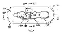
図4及び5は、例えば図1〜3の外科的固定のシステム10のような外科的固定のシステムとともに使用される典型的な固定デバイス12を示す。固定デバイス12は、頂面27(図4参照)及び底面29(図5参照)を含み得る。側壁31が、固定デバイス12の本体を確立するべく頂面27と底面29との間に延びる。一実施形態において、固定デバイス12の本体は長円形状とされる。 FIGS. 4 and 5 show a
アパチャ20A、20B及び20Cが、固定デバイス12の頂面27及び底面29双方を通過する。一実施形態において、固定デバイス12は3つのアパチャを含み得る。固定デバイス12の中間近くの2つのアパチャ20A、20Bは、ループ14を取り付けるべく使用することができる一方、周縁アパチャ20Cは、固定デバイス12を骨に対して通過させ及び/又は反転させるための通過縫合糸を担持するべく使用される。一実施形態において、アパチャ20A及び20Cは円形であり、アパチャ20Cはティアドロップ形状である。他の形状、及び形状の組み合わせもまた考慮される。
ブリッジ33は、アパチャ20A、20Bを互いから分離し、外科的固定のシステム10のループ14を担持する表面を与える。ブリッジ33は、頂面27に溝35を確立するべく頂面27からの皿穴としてよい。ループ14の結び目スタック25は、少なくとも部分的にチャネル35内に受容される。
ブリッジ33は、底面29(図5参照)においては皿穴としなくともよい。結び目スタック25を固定デバイス12の当該側に収容する必要がないからである。よって、固定デバイス12の底面29は一般に平坦としてよい。他の言い方をすれば、頂面27と底面29とは互いに非対称であってよい。 The
図6〜14は、図1〜3の外科的固定のシステム10のループ14を形成する典型的な方法を模式的に示す。図6は、ループ14を構築して固定デバイス12に取り付ける開始材料を示す。開始材料は、例えば、縫合ストランドのような可撓性ストランド26、ニードルのような縫合糸通過デバイス28、及びボタンのような固定デバイス12を含む。 6-14 schematically illustrate an exemplary method of forming the
次に図7を参照すると、可撓性ストランド26が、2つの実質的に等しい長さをもたらし、この例において、平行な編みストランドをもたらすように、半分に折り曲げられる。可撓性ストランド26は、2つの実質的に等しい長さをもたらし、この例において、平行な編みストランドをもたらすように、中点M近くで折り曲げられてもよい。所望サイズを有するループ14をもたらす可撓性ストランド26の所望量を選択するべく、定規のような測定デバイス30を使用してよい。 Referring now to FIG. 7, a
図8及び9は、ループ14の第1調整可能アイスプライスループ24A形成の一例を示す。第1調整可能アイスプライスループ24Aは、最初に、縫合糸通過デバイス28を、可撓性ストランド26を通るように通過させることによってもたらされ得る(図8参照)。縫合糸通過デバイス28は、中点M近くにおいて可撓性ストランド26に通される。ここで、可撓性ストランド26は、可撓性ストランド26が究極的に自身を通って組み継がれる箇所の印を付けるように、事前に折り曲げられている。次に、可撓性ストランド26の第1自由端32が、縫合糸通過デバイス28のアイレット34を通るように挿入される(図9参照)。縫合糸通過デバイス28がその後、矢印36の方向に動かされ(例えば引っ張られ)、縫合糸通過デバイス28が事前に可撓性ストランド26を通されている箇所において、第1自由端32が、可撓性ストランド26を後方に通って組み継がれる。これにより、第1組み継ぎセクション38が可撓性ストランド26にもたらされる。 8 and 9 show an example of the formation of the first adjustable
ここで図10を参照すると、第1調整可能アイスプライスループ24Aは、固定デバイス12の複数のアパチャ20のうちの一つを通過し、可撓性ストランド26と固定デバイス12との接続が開始される。固定デバイス12は、この例においては第1組み継ぎセクション38の直上に載置されるまで摺動され得る。 Referring now to FIG. 10, the first adjustable
図11は、ループ14の第2調整可能アイスプライスループ24Bの形成を示す。可撓性ストランド26の第2自由端40を、第1調整可能アイスプライスループ24Aを通してループにした後、縫合糸通過デバイス28のアイレット34に挿入することができる。その後、縫合糸通過デバイス28が、可撓性ストランド26を通して引っ張られる。これにより、第2自由端40が可撓性ストランド26を後方に通り、第2組み継ぎセクション56がもたらされる。このようにして、第1調整可能アイスプライスループ24Aと第2調整可能アイスプライスループ24Bとが、この例では究極的に固定デバイス12のブリッジ33の上に載置される相互接続部70において、相互連結されるようになる。これによりさらに、ループ14が固定デバイス12に固定的に接続され得る。 FIG. 11 shows the formation of the second adjustable
ここで図12及び13を参照すると、第1調整可能アイスプライスループ24Aは第1自由編みストランド22Aを含み、第2調整可能アイスプライスループ24Bは第2自由編みストランド22Bを含む。第1自由編みストランド22A及び第2自由編みストランド22Bは、固定デバイス12の、結び目スタック25から反対側に、位置決めすることができる。第1自由編みストランド22Aは、例えば、(図12及び13に示されるように構築物を見下ろした場合に)構築物の右側において第3組み継ぎセクション72をもたらすべく、可撓性ストランド26のクレードル18を通るように引っ張り戻すことができる。第2自由編みストランド22Bは、例えば、構築物の左側において第4組み継ぎセクション74をもたらすべく、可撓性ストランド26のクレードル18を通るように引っ張り戻すことができる。 Referring now to FIGS. 12 and 13, a first adjustable
図14は、完成したループ14を示す。これは、この実施形態において、相互接続部70において互いに相互連結した2つの調整可能アイスプライスループ24A、24Bを含む。固定デバイス12は、第1調整可能アイスプライスループ24Aと第2調整可能アイスプライスループ24Bとの間に中心を有して組み付け手順を完成させ得る。組み継ぎセクション72、74から延びる自由編みストランド22A、22Bは、固定デバイス12のアパチャ20を戻るように通過し得る。次に、第1自由編みストランド22Aが第1調整可能アイスプライスループ24Aを通過し、第2自由編みストランド22Bが第2調整可能アイスプライスループ24Bを通過し、それゆえ、結び目スタック25の形成が完成する。 FIG. 14 shows the completed
自由編みストランド22A、22Bは、第1調整可能アイスプライスループ24A及び第2調整可能アイスプライスループ24Bそれぞれのサイズを収縮させるべく引っ張ることができる。それにより、ループ14の全体的なサイズを変更することができる。結び目スタック25は、ループ14/固定デバイス12接合部において第1ロック機構として作用し得る。組み継ぎセクション72、74は、この例においては遠位移植片16/ループ14接合部において、付加的ロック機構として作用し得る。 The
図15は、ACL再建処置のような組織再建処置中の、図1〜3の外科的固定のシステム10の典型的な外科的使用を示す。しかしながら、本開示がACL再建処置に限られることはなく、外科的固定のシステム10が、本開示の範囲内で様々な再建処置において使用し得ることを理解すべきである。 FIG. 15 illustrates a typical surgical use of the
外科的固定のシステム10は、破裂組織(例えば破裂ACL)を修復するべく関節45(例えば膝関節)にインプラントされてよい。外科的固定のシステム10を関節45内に位置決めするのに先立って、第1骨トンネル42(例えばソケット)が第1骨44(例えば大腿骨)に形成され、第2骨トンネル46(例えば通路)が第2骨48(例えば脛骨)に形成される。外科的固定のシステム10を収容する第1骨44及び第2骨48の中に空隙を確立するべく、第1骨トンネル42及び第2骨トンネル46を、周知のドリル技法を使用して形成することができる。 The
典型的な実施形態において、外科的固定のシステム10は、固定デバイス12に第1骨トンネル42及び第2骨トンネル46を通過させることによってインプラントされる。固定デバイス12は、通過縫合糸(図示せず)を使用して、第1骨トンネル42及び第1骨トンネル46を通るように引っ張ることができ、ひとたび通過縫合糸の張力が解放されると第1骨44の皮質へと自己反転する。 In an exemplary embodiment, the
固定デバイス12が通過及び反転した後、ループ14が第1骨トンネル42の中に位置決めされる。自由編みストランド22を、ループ14のサイズを調整するべく、及びループ14の第1骨トンネル42内の位置決めの補助をするべく、引っ張ることができる。ループ14は、移植片16を、第1骨トンネル42及び第2骨トンネル46の位置内に懸架する。 After the
第2骨48への移植片16の固定は、様々な態様で達成することができる。例えば、移植片16は、干渉ねじ、縫合糸アンカー、又は、第2固定装置及び第2ループを含む付加的な外科的固定のシステムを使用して、第2骨トンネル46内に固定することができる。 The fixation of the
伸長試験 Extension test
図1〜3の外科的固定のシステム10が、先行技術の外科的固定のシステムに対し、力制御サイクル荷重手順を使用して試験された。各システムに対して多数の荷重サイクルにわたって伸長が測定された。この試験の結果を図16のプロットに示す。 The
変位試験 Displacement test
図1〜3の外科的固定のシステム10が、変位制御サイクル荷重手順を使用して試験された。多数の荷重サイクルにわたって変位が測定された。この試験の結果を図17のプロットに示す(再緊張あり及びなし)。 The
本開示の外科的固定のシステムは、骨トンネル内の移植片固定の強化及び増強を調整可能な固定のシステムを与える。外科的固定のシステムは、従前のデバイスに対して以下の利益を与える。
・独立したロック機構
・ほとんどの従前デバイスよりも高い破壊荷重(〜1400N)
・荷重解放/荷重付加遷移ゾーン(1kサイクル)、10〜250N(1kサイクル)、及び10〜400N(1kサイクル)の荷重ブロックでの3000サイクル後の、ほとんどの従前デバイスよりも少ないサイクル変位(〜0.9mm)
・移植片の下方の力が、結び目スタックを固定デバイスのチャネルの中へと圧縮することにより、短縮ストランドを固定すること
・結び目スタックを介した固定デバイス側への結び目なしロック機能
・単一緊張システム使用時の縫合糸破断を低減する単一ループの緊張(片手の引っ張り)機構、及び縫合糸管理の混乱低減
・様々な構成(例えばABS、BTB、PCL)で使用できる能力
・足首又はAC関節のような他の関節への適用可能性
・様々な付加的縫合糸構成を実装できる能力The surgical fixation system of the present disclosure provides an adjustable fixation and enhancement of graft fixation in a bone tunnel. Surgical fixation systems offer the following benefits over previous devices.
• Independent locking mechanism • Higher breaking load (~ 1400N) than most previous devices
• Less cyclic displacement than most previous devices after 3000 cycles with load release / load transition zone (1 k cycle), 10-250 N (1 k cycle), and 10-400 N (1 k cycle) load block. 0.9mm)
Securing the shortened strands by the force below the implant compressing the knot stack into the channels of the anchoring device; the knotless locking function to the anchoring device side via the knot stack; single tension Single-loop tensioning (one-handed pull) mechanism to reduce suture breaks when using the system, and reduced confusion in suture management. Ability to be used in various configurations (eg ABS, BTB, PCL). Ankle or AC joint. Applicability to other joints, such as the ability to implement various additional suture configurations
図18は、他の典型的な外科的固定のシステム110を示す。外科的固定のシステム110は、様々な組織再建処置を行うべく使用してよい。 FIG. 18 illustrates another exemplary
外科的固定のシステム110は、この例において、固定デバイス112と、固定デバイス112に接続されたループ114とを含む。一実施形態において、ループ114は、例えば、骨に対して移植片116を固定するべく、移植片116を担持する。 The
固定デバイス112は、例えば、骨トンネル内の移植片116の位置決めが完了した後、移植片16(又はフィラメント)の皮質骨固定を与えることができる。一実施形態において、固定デバイス112はボタンである。しかしながら、他の同様の構成を有するデバイスも使用することができる。固定デバイス112は長円又は円としてよく、本開示の範囲内において金属材料又はポリマー材料のいずれから作ることもできる。2つの典型的な固定デバイス設計が、以下にさらに記載される(図19〜22及び図25〜28をそれぞれ参照)。 The
他実施形態において、固定デバイス112は、ループ114を受容するべく、固定デバイス112の本体を通るように形成された複数のアパチャ120を含む。複数のアパチャ120のいくつかは、付加的に、縫合糸のような一つ以上のフィラメント115を担持することができる。一つ以上のフィラメント115は、固定デバイス112に骨トンネルを通過させるべく、及び/又は骨トンネルから延びた後に骨に対して固定デバイス112を反転させるべく、使用することができる。 In another embodiment, the
一実施形態において、ループ114は、可撓性材料から作られた調整可能ループであり、この例においては、調整可能な長さ及び/又は周縁を含み得る。ループ114の自由編みストランド122A、122Bは、短縮ストランドとも称するが、ループ114のサイズを低減させるべく引っ張ることができる。例えば、ループ114は、自由編みストランド122A、122Bによって引っ張られて第1方向に調整され得るが、適用された内部引っ張り力に起因して反対方向に緩むことが防止される。 In one embodiment,
ループ114は、一つ以上の調整可能アイスプライスループ124A、124Bを含み得る。これらは、自身を通ってループ114を形成するべく使用され得る可撓性材料を組み継ぐことによって形成することができる。ループ114は、ループ114を完全に形成するのに先立って固定デバイス112に接続することができる。
移植片116は、ループ114のクレードル118に接続される。一実施形態において、移植片116は、ループ114のクレードル118越しにループを形成してよい。この実施形態におけるクレードル118は、アイスプライスループ124A、124Bの相互接続部119によって確立される。移植片116は、組織、腱、靭帯、フィラメント(例えば縫合糸)、合成材料、生物学的材料、骨、又はかかる材料の任意の組み合わせを含み得る。
一実施形態において、ループ114と固定デバイス112とは、外科的固定のシステム110のロック機構199を確立するべく協働することができる。ロック機構199は、固定デバイス112に対してループ114のサイズ及び位置をロックし、ひいては、ループ114/固定デバイス112接合部における強度を増大させる。ロック機構199は、ループ114及び固定デバイス112の特徴部の組み合わせの副産物としてよい。ロック機構199は、固定デバイス112の異なる設計を参照して以下に詳述される。 In one embodiment, the
図19〜22は、例えば図18の外科的固定のシステム110のような外科的固定のシステムとともに使用される典型的な固定デバイス112Aを示す。固定デバイス112Aは、対向する端部分117の間に中心長手軸Aに沿って延びる本体113を含む。一実施形態において、固定デバイス112Aの本体113は、長円形状とされる。 19-22 illustrate an
本体113は、対向する端部分117の間にそれぞれが延びる頂面127及び底面129を含む。側壁131が、頂面127と底面129との間に延びる。頂面127、底面129及び側壁131が一緒になって、固定デバイス112Aの本体113を確立する。
一実施形態において、頂面127は、底面129から離れる方向に曲がる凸面である。他実施形態において、底面129は平坦面である。 In one embodiment,
この例において、第1アパチャ120A、第2アパチャ120B、第3アパチャ120C及び第4アパチャ120Dが、固定デバイス112Aの本体113を通るように形成され、頂面127及び底面129双方を通るように延びる。一実施形態において、第1アパチャ120A、第2アパチャ120B及び第3アパチャ120Cは、軸方向に整列され、中心長手軸Aに沿って配置される。第4アパチャ120Dは、中心長手軸Aから、例えば側壁131に向かう方向にずらされ得る。一実施形態において、第1アパチャ120A及び第2アパチャ120Bは不規則な形状を含み、第3アパチャ120C及び第4アパチャ120Dは楕円形状とされる。しかしながら、これらのアパチャのサイズ及び形状が本開示に限られることを意図しない。 In this example, a
第1アパチャ120A及び第2アパチャ120Bは、外科的固定のシステム110のループ114を受容するべく構成及び配列することができる。ブリッジ133は、第1アパチャ120Aと第2アパチャ120Bとを互いから分離させ、外科的固定のシステム10のループ14を担持する表面を与え得る。ブリッジ133は、固定デバイス112Aの頂面127と面一な外表面137と(すなわち、外表面137は、頂面127に対して皿穴とはなっていない)、例えばブリッジ133から側方に固定デバイス112Aの底面129に向かう方向に延びる一対の傾斜面139とを含み得る。一実施形態において、ブリッジ133の外表面137は、例えば、本体113の中心長手軸Aに一般に垂直な長手軸A2に沿って延びる(図19参照)。
第3アパチャ120Cは、骨トンネルを通るように固定デバイス112Aを通過させ、及び/又は骨トンネルから出た後に骨に対して固定デバイス112Aを反転させる一つ以上のフィラメント115を担持するべく使用することができる。第3アパチャ120Cは、固定デバイス112Aの対向端部分117の一方に最も近いアパチャとしてよい。 The
第4アパチャ120Dは、ループ114の自由編みストランド122A、122Bを受容する縫合糸戻りアパチャとして利用することができる。第4アパチャ120Dは、第1アパチャ120A及び第2アパチャ120Bに隣接するように配置することができる。一実施形態において、ブリッジ133の外表面137を通って延びる長手軸A2は、第4アパチャ120Dと交差する(図19参照)。 The
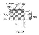
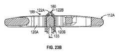
ここで図18〜22を参照すると、固定デバイス112A及びループ114が、外科的固定のシステム110のロック機構199を確立するべく構成され得る。一実施形態において、第1自由編みストランド122Aが、ループ114の第1組み継ぎセクション172から延び、第2自由編みストランド122Bが、ループ114の第2組み継ぎセクション174から延びる。第1自由編みストランド122A及び第2自由編みストランド122Bは、この例においては、第4アパチャ120Dを通って上方(すなわち固定デバイス112Aの底面129から頂面127に向かって延びる方向)に向かい、その後、ループ114のループセクション180の下を通され、例えば、ブリッジ133の上に(すなわちループセクション180とブリッジ133との間に)載置され、ロック機構199が確立される。 Referring now to FIGS. 18-22, the
図23A及び23Bは、ループ114及び固定デバイス112Aにより確立されたロック機構199のロック位置L1を示す。ロック位置L1において、自由編みストランド122A及び122Bは、ループ114のループセクション180により、ブリッジ133の外表面137に直接当接するように緊張して保持される。この張力は、例えば、ループ114の対向セクション(すなわち、例えば移植片116を担持するクレードル118)を緊張させることによってもたらされる。したがって、自由編みストランド122A、122Bは、ループ114の第1調整可能アイスプライスループ124A及び第2調整可能スプライスループ124Bのサイズを収縮させるのに必要なタイプの動きに抵抗するように保持される。 FIGS. 23A and 23B show the lock position L1 of the
図24A及び24Bは、ループ114及び固定デバイス112Aにより確立されたロック機構199のロック解除位置L2を示す。ロック解除位置L2において、自由編みストランド122A及び122Bに対してループセクション180を保持する張力が、例えば、移植片116への張力を解放することによって、解放される。これにより、自由編みストランド122A、122Bが、ブリッジ133及びループセクション180に対して動くことが許容される。ループセクション180により適用される張力がひとたび除去されると、自由編みストランド122A、122Bは、ループ114の第1及び/又は第2調整可能アイスプライスループ124A、124Bのサイズを収縮させるべく、例えば、方向D1に緊張することができる。 FIGS. 24A and 24B show the unlocked position L2 of the
図25〜28は、例えば図18の外科的固定のシステム110のような外科的固定のシステムとともに使用される典型的な固定デバイス112Bを示す。固定デバイス112Bは、対向する端部分117の間に中心長手軸Aに沿って延びる本体113を含む。一実施形態において、固定デバイス112Bの本体113は、長円形状とされる。 25-28 illustrate an
本体113は、対向する端部分117の間にそれぞれが延びる頂面127及び底面129を含む。側壁131が、頂面127と底面129との間に延びる。頂面127、底面129及び側壁131が一緒になって、固定デバイス112Bの本体113を確立する。
一実施形態において、頂面127は、底面129から離れる方向に曲がる凸面である。他実施形態において、底面129は平坦面である。 In one embodiment,
例えば、第1アパチャ120A、第2アパチャ120B、第3アパチャ120C及び第4アパチャ120Dを、固定デバイス112Bの本体113を通るように形成することができ、頂面127及び底面129双方を通るように延ばすことができる。一実施形態において、第1アパチャ120A、第2アパチャ120B及び第3アパチャ120Cは、軸方向に整列され、例えば中心長手軸Aに沿って配置され得る。第4アパチャ120Dは、中心長手軸Aから、例えば側壁131に向かう方向にずらされ得る。一実施形態において、第1アパチャ120A及び第2アパチャ120Bは不規則な形状を含み、第3アパチャ120C及び第4アパチャ120Dは楕円形状とされる。しかしながら、これらのアパチャのサイズ及び形状が本開示に限られることを意図しない。 For example, the
第1アパチャ120A及び第2アパチャ120Bは、外科的固定のシステム110のループ114を受容するべく配列することができる。ブリッジ133は、第1アパチャ120Aと第2アパチャ120Bとを互いから分離させ、外科的固定のシステム10のループ14を担持する表面を与える。ブリッジ133は、固定デバイス112Bの頂面127と面一な外表面137と(すなわち、外表面137は、頂面127に対して皿穴とはなっていない)、例えばブリッジ133から側方に固定デバイス112Bの底面129に向かう方向に延びる一対の傾斜面139とを含み得る。一実施形態において、ブリッジ33の外表面137は、本体113の中心長手軸Aに一般に垂直な長手軸A2に沿って延びる(図25参照)。 The
第3アパチャ120Cは、骨トンネルを通るように固定デバイス112Bを通過させ、及び/又は骨トンネルから出た後に骨に対して固定デバイス112を反転させる一つ以上のフィラメント115を担持するべく使用することができる。第3アパチャ120Cは、例えば、固定デバイス112Bの対向端部分117の一方に最も近いアパチャとしてよい。 The
第4アパチャ120Dは、ループ114の自由編みストランド122A、122Bを受容する縫合糸戻りアパチャとして利用することができる。第4アパチャ120Dは、第1アパチャ120A及び第2アパチャ120Bに隣接するように配置することができる。一実施形態において、ブリッジ133の外表面137を通って延びる長手軸A2は、第4アパチャ120Dと交差する(図25参照)。 The
隆起182を、固定デバイス112Bのブリッジ133と第4アパチャ120Dとの間に短手方向に位置決めすることができる。隆起182は、固定デバイス112Bの頂面127及びブリッジ133の外表面137から外方に突出してよい。この例におけるブリッジ133の外表面137とは異なり、したがって、隆起182は、頂面127に対して面一ではない。 The
図18及び25〜28を参照すると、固定デバイス112B及びループ114は、外科的固定のシステム110のロック機構199を確立するべく構成することができる。一実施形態において、第1自由編みストランド122Aが、ループ114の第1組み継ぎセクション172から延び、第2自由編みストランド122Bが、ループ114の第2組み継ぎセクション174から延びる。第1自由編みストランド122A及び第2自由編みストランド122Bは、この例においては、第4アパチャ120Dを通って上方(すなわち、例えば固定デバイス112Aの底面129から頂面127に向かって延びる方向)に向かい、その後、蛇行経路を上へと通過して隆起182を超え、その後、ループ114のループセクション180の下を通され、例えば、ブリッジ133の上に載置され、ロック機構199が確立される。 Referring to FIGS. 18 and 25-28, the
図29A及び29Bは、ループ114及び固定デバイス112Bにより確立されたロック機構199のロック位置L1を示す。ロック位置L1において、自由編みストランド122A及び122Bは、ループ114のループセクション180により、ブリッジ133の外表面137に直接当接するように緊張して保持される。この張力は、例えば、ループ114の対向セクション(すなわち、例えば移植片116を担持するセクション)を緊張させることによってもたらされる。固定デバイス112Bの隆起182により、ロック位置L1において自由編みストランド122A、122Bに対して及ぼされ得る張力の量が増大し得る。したがって、自由編みストランド122A、122Bは、ループ114の第1調整可能アイスプライスループ124A及び第2調整可能スプライスループ124Bのサイズを収縮させるのに必要なタイプの動きに抵抗するように保持される。 29A and 29B show the lock position L1 of the
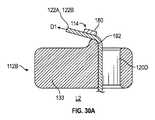
図30A及び30Bは、ループ114及び固定デバイス112Bにより確立されたロック機構199のロック解除位置L2を示す。ロック解除位置L2において、自由編みストランド122A及び122Bに対してループセクション180を保持する張力が、例えば、移植片116への張力を解放することによって、解放される。これにより、自由編みストランド122A、122Bが、ブリッジ133、ループセクション182及び隆起182に対して動くことが許容される。ループセクション180により適用される張力がひとたび除去されると、自由編みストランド122A、122Bは、ループ114の第1及び/又は第2調整可能アイスプライスループ124A、124Bのサイズを収縮させるべく、方向D1に緊張することができる。 30A and 30B show the unlocked position L2 of the
異なる非制限的な複数の実施形態が特定のコンポーネント又はステップを有するように示されるにもかかわらず、本開示の複数の実施形態はそれらの特定の組み合わせに限られない。非制限的な複数の実施形態のいずれかからのコンポーネント又は特徴物のいくつかを、他の非制限的な複数の実施形態のいずれかからの特徴物又はコンポーネントと組み合わせて使用することが可能である。 Although different, non-limiting embodiments are shown to have particular components or steps, embodiments of the present disclosure are not limited to the particular combinations thereof. Some of the components or features from any of the non-limiting embodiments may be used in combination with features or components from any of the other non-limiting embodiments. is there.
理解すべきことだが、同じ参照番号は、いくつかの図面にわたり、対応する又は同様の要素を特定する。さらに理解すべきことだが、これらの典型的な実施形態において特定のコンポーネント配列が開示かつ図示されるにもかかわらず、他の配列も本開示の教示から利益を受け得る。 It should be understood that the same reference numbers identify corresponding or similar elements throughout the several views. It should be further understood that, although specific component arrangements are disclosed and illustrated in these exemplary embodiments, other arrangements may benefit from the teachings of the present disclosure.
上記説明は、例示として解釈され、いずれの制限的な意味としても解釈されない。当業者であれば理解することだが、所定の修正例が本開示の範囲内に入り得る。これらの理由により、本開示の真の範囲及び内容を決定するには、以下の特許請求の範囲を精査するべきである。
The above description is to be construed as illustrative and not in any limiting sense. As those skilled in the art will appreciate, certain modifications may be within the scope of the present disclosure. For these reasons, the following claims should be studied to determine the true scope and content of this disclosure.
Claims (20)
Translated fromJapanese固定デバイスと、
前記固定デバイスに接続されて第1調整可能アイスプライスループを含む調整可能ループと
を含み、
前記第1調整可能アイスプライスループは、前記固定デバイスのブリッジの上に載置される相互接続部において、第2調整可能アイスプライスループを通過して前記第2調整可能アイスプライスループと相互連結される、システム。A surgical fixation system,
A fixed device;
An adjustable loop connected to the fixation device and including a first adjustable ice price loop;
The first adjustable ice price loop is interconnected with the second adjustable ice price loop through a second adjustable ice price loop at an interconnect mounted on a bridge of the securing device. System.
前記第2調整可能アイスプライスループは、前記固定デバイスの第2アパチャを通るように受容される、請求項1から4のいずれか一項に記載のシステム。The first adjustable ice price loop is received through a first aperture of the fixation device;
The system of any of the preceding claims, wherein the second adjustable ice price loop is received through a second aperture of the fixation device.
前記第1調整可能アイスプライスループを調整する第1自由編みストランドと、
前記第2調整可能アイスプライスループを調整する第2自由編みストランドと
を含む、請求項1から5のいずれか一項に記載のシステム。The adjustable loop comprises:
A first free knitting strand for adjusting the first adjustable ice price loop;
And a second free-knit strand for adjusting the second adjustable ice price loop.
前記第2自由編みストランドは前記第1調整可能アイスプライスループを通過する、請求項6に記載のシステム。The first free knitting strand passes through the second adjustable ice price loop;
7. The system of claim 6, wherein the second free knitting strand passes through the first adjustable ice price loop.
前記第2自由編みストランドは、前記第1調整可能アイスプライスループを通過するのに先立って前記固定デバイスの第2開口を通過する、請求項7に記載のシステム。The first free knitting strand passes through a first opening of the fixation device prior to passing through the second adjustable ice price loop;
The system according to claim 7, wherein the second free knitting strand passes through a second opening of the fixation device prior to passing through the first adjustable ice price loop.
前記結び目スタックは、前記固定デバイスの前記ブリッジの上に載置される、請求項6から10のいずれか一項に記載のシステム。The first adjustable ice price loop, the second adjustable ice price loop, and the free knitting strands of the adjustable loop cooperate to tie a knot between the adjustable loop and the securing device. Establish a stack,
The system according to any one of claims 6 to 10, wherein the knot stack rests on the bridge of the fixation device.
請求項1から11のいずれか一項に記載の外科的固定のシステムにより、骨トンネル内に移植片を固定することを含む、外科的方法。A surgical method,
A surgical method, comprising fixing an implant in a bone tunnel with the surgical fixation system according to any one of claims 1 to 11.
中心長手軸に沿って延びる本体を含むとともに頂面及び底面を含む固定デバイスと、
それぞれが前記本体を通って延びる第1アパチャ、第2アパチャ及び縫合糸戻りアパチャと、
前記第1アパチャと前記第2アパチャとの間に延びるブリッジと、
前記第1アパチャ及び前記第2アパチャに接続された調整可能ループと、
前記調整可能ループの第1組み継ぎセクションから延びる第1自由編みストランドと、
前記調整可能ループの第2組み継ぎセクションから延びる第2自由編みストランドと
を含み、
前記第1自由編みストランド及び前記第2自由編みストランドは、前記縫合糸戻りアパチャを通り、その後、前記ブリッジの上に載置された前記調整可能ループのループセクションの下を通ることにより、前記外科的固定のシステムのロック機構を確立し、
前記ロック機構のロック位置において、前記第1自由編みストランド及び前記第2自由編みストランドは、前記調整可能ループの前記ループセクションによって、前記ブリッジの外表面に当接するように張力を受ける、システム。A surgical fixation system,
An anchoring device including a body extending along a central longitudinal axis and including a top surface and a bottom surface;
A first aperture, a second aperture and a suture return aperture each extending through the body;
A bridge extending between the first aperture and the second aperture;
An adjustable loop connected to the first aperture and the second aperture;
A first free knitting strand extending from a first splice section of the adjustable loop;
A second free knitting strand extending from a second splice section of the adjustable loop;
The first free knitting strand and the second free knitting strand pass through the suture return aperture, and then pass under the loop section of the adjustable loop resting on the bridge, thereby providing the surgical knitted strand. Establish a locking mechanism for the fixed system,
In the locked position of the locking mechanism, the first free knitting strand and the second free knitting strand are tensioned by the loop section of the adjustable loop to abut the outer surface of the bridge.
前記縫合糸戻りアパチャは、前記中心長手軸から、前記本体の側壁に向かう方向にずらされる、請求項13から15のいずれか一項に記載のシステム。The first aperture and the second aperture are axially aligned and arranged along the central longitudinal axis;
16. The system of any one of claims 13 to 15, wherein the suture return aperture is offset from the central longitudinal axis in a direction toward a sidewall of the body.
請求項13から19のいずれか一項に記載の外科的固定のシステムにより、骨トンネル内に移植片を固定することを含む、外科的方法。
A surgical method,
A surgical method comprising fixing a graft in a bone tunnel with the system of surgical fixation according to any one of claims 13 to 19.
Priority Applications (1)
| Application Number | Priority Date | Filing Date | Title |
|---|---|---|---|
| JP2021103022AJP2021154149A (en) | 2017-03-13 | 2021-06-22 | Surgical fixation systems |
Applications Claiming Priority (3)
| Application Number | Priority Date | Filing Date | Title |
|---|---|---|---|
| US201762470522P | 2017-03-13 | 2017-03-13 | |
| US62/470,522 | 2017-03-13 | ||
| PCT/US2018/022190WO2018169961A1 (en) | 2017-03-13 | 2018-03-13 | Surgical fixation systems and methods |
Related Child Applications (1)
| Application Number | Title | Priority Date | Filing Date |
|---|---|---|---|
| JP2021103022ADivisionJP2021154149A (en) | 2017-03-13 | 2021-06-22 | Surgical fixation systems |
Publications (2)
| Publication Number | Publication Date |
|---|---|
| JP2020509856Atrue JP2020509856A (en) | 2020-04-02 |
| JP6974488B2 JP6974488B2 (en) | 2021-12-01 |
Family
ID=61906833
Family Applications (2)
| Application Number | Title | Priority Date | Filing Date |
|---|---|---|---|
| JP2019549572AActiveJP6974488B2 (en) | 2017-03-13 | 2018-03-13 | Surgical fixation system |
| JP2021103022AWithdrawnJP2021154149A (en) | 2017-03-13 | 2021-06-22 | Surgical fixation systems |
Family Applications After (1)
| Application Number | Title | Priority Date | Filing Date |
|---|---|---|---|
| JP2021103022AWithdrawnJP2021154149A (en) | 2017-03-13 | 2021-06-22 | Surgical fixation systems |
Country Status (6)
| Country | Link |
|---|---|
| US (2) | US11723645B2 (en) |
| EP (2) | EP4609826A2 (en) |
| JP (2) | JP6974488B2 (en) |
| AU (1) | AU2018236196B2 (en) |
| CA (1) | CA3055945C (en) |
| WO (1) | WO2018169961A1 (en) |
Families Citing this family (12)
| Publication number | Priority date | Publication date | Assignee | Title |
|---|---|---|---|---|
| US20200093514A1 (en)* | 2018-09-25 | 2020-03-26 | In2Bones Usa, Llc | Syndesmosis treatment construct |
| JP7425055B2 (en)* | 2018-11-02 | 2024-01-30 | アースレックス インコーポレイテッド | Surgical fixation systems and related methods for performing tissue repair |
| GB201819426D0 (en)* | 2018-11-29 | 2019-01-16 | Xiros Plc | Implant assembly and associated methods |
| EP3917411A1 (en)* | 2019-03-05 | 2021-12-08 | Arthrex, Inc | Surgical fixation systems and associated methods |
| US20220233302A1 (en)* | 2019-06-18 | 2022-07-28 | Smith & Nephew, Inc. | Methods and devices for tissue graft fixation |
| US11272920B2 (en) | 2019-09-26 | 2022-03-15 | Medos International Sarl | One-way adjustable loop suture constructs and methods of forming and using the same |
| US11690612B2 (en)* | 2019-12-24 | 2023-07-04 | Arthrex, Inc. | Self-locking surgical constructs and methods of use |
| WO2022094434A1 (en) | 2020-10-30 | 2022-05-05 | Anderson M D Christian | Dynamic ligament repair device |
| US20240197314A1 (en) | 2021-05-20 | 2024-06-20 | Arthrex, Inc. | Knotless All-Inside Suture Constructs and Methods of Tissue Fixation |
| US20230355228A1 (en)* | 2022-05-03 | 2023-11-09 | Arthrex, Inc. | Suture-to-button assemblies for performing surgical procedures |
| US12426871B2 (en) | 2022-08-24 | 2025-09-30 | Globus Medical, Inc. | Systems, devices and methods for implanting suture buttons |
| CN116327283A (en)* | 2023-03-29 | 2023-06-27 | 海南苏生生物科技有限公司 | A kind of threading method of titanium plate and matching wire |
Citations (8)
| Publication number | Priority date | Publication date | Assignee | Title |
|---|---|---|---|---|
| US5769894A (en)* | 1997-02-05 | 1998-06-23 | Smith & Nephew, Inc. | Graft attachment device and method of attachment |
| US20060190041A1 (en)* | 2003-06-11 | 2006-08-24 | Medicinelodge, Inc. | Compact line locks and methods |
| US20100268273A1 (en)* | 2009-03-31 | 2010-10-21 | Ricardo Albertorio | Adjustable suture button construct and methods of tissue reconstruction |
| US20110087280A1 (en)* | 2009-10-14 | 2011-04-14 | Ricardo Albertorio | Z-shaped button for tissue repair |
| JP2012505049A (en)* | 2008-10-10 | 2012-03-01 | ガイデッド デリバリー システムズ, インコーポレイテッド | Tether tensioning device and related methods |
| US20120290002A1 (en)* | 2011-05-12 | 2012-11-15 | Smith & Nephew, Inc. | Tissue graft anchoring |
| US20130197580A1 (en)* | 2012-02-01 | 2013-08-01 | Smith & Nephew, Inc. | Tissue graft anchoring |
| US20150196385A1 (en)* | 2014-01-16 | 2015-07-16 | Linvatec Corporation | Suspensory graft fixation with adjustable loop length |
Family Cites Families (13)
| Publication number | Priority date | Publication date | Assignee | Title |
|---|---|---|---|---|
| US9005245B2 (en)* | 2002-08-30 | 2015-04-14 | Arthrex, Inc. | Acromioclavicular joint fixation technique |
| US8439976B2 (en)* | 2009-03-31 | 2013-05-14 | Arthrex, Inc. | Integrated adjustable button-suture-graft construct with two fixation devices |
| EP2263608B1 (en)* | 2009-06-19 | 2016-09-07 | Arthrex, Inc. | Bone-tendon-bone suture button construct |
| US8864797B2 (en)* | 2009-07-02 | 2014-10-21 | Coorstek Medical Llc | Systems and methods for intra-operative tension and fixation of zipknot ACL fixation |
| US20120109194A1 (en)* | 2010-10-28 | 2012-05-03 | Linvatec Corporation | Suspensory graft fixation with adjustable loop length |
| EP2455002B1 (en)* | 2010-11-17 | 2019-04-03 | Arthrex, Inc. | Adjustable suture-button construct for ankle syndesmosis repair |
| EP2455001B1 (en)* | 2010-11-17 | 2020-07-22 | Arthrex, Inc. | Adjustable suture-button constructs for ligament reconstruction |
| US9192368B2 (en) | 2011-08-04 | 2015-11-24 | Smith & Nephew, Inc. | Suspension device to anchor tissue graft |
| US9357990B2 (en)* | 2012-05-22 | 2016-06-07 | Riverpoint Medical, Llc | Continuous loop and button assembly |
| US10052094B2 (en)* | 2013-03-11 | 2018-08-21 | Medos International Sàrl | Implant having adjustable filament coils |
| US9974643B2 (en)* | 2013-03-11 | 2018-05-22 | Medos International Sàrl | Implant having adjustable filament coils |
| US9757113B2 (en) | 2013-07-31 | 2017-09-12 | Medos International Sàrl | Adjustable graft fixation device |
| US10405968B2 (en) | 2013-12-11 | 2019-09-10 | Medos International Sarl | Implant having filament limbs of an adjustable loop disposed in a shuttle suture |
- 2018
- 2018-03-13AUAU2018236196Apatent/AU2018236196B2/enactiveActive
- 2018-03-13EPEP25189770.8Apatent/EP4609826A2/enactivePending
- 2018-03-13JPJP2019549572Apatent/JP6974488B2/enactiveActive
- 2018-03-13USUS16/491,049patent/US11723645B2/enactiveActive
- 2018-03-13CACA3055945Apatent/CA3055945C/enactiveActive
- 2018-03-13WOPCT/US2018/022190patent/WO2018169961A1/ennot_activeCeased
- 2018-03-13EPEP18716030.4Apatent/EP3595540B1/enactiveActive
- 2021
- 2021-06-22JPJP2021103022Apatent/JP2021154149A/ennot_activeWithdrawn
- 2023
- 2023-07-28USUS18/361,215patent/US20230380831A1/enactivePending
Patent Citations (11)
| Publication number | Priority date | Publication date | Assignee | Title |
|---|---|---|---|---|
| US5769894A (en)* | 1997-02-05 | 1998-06-23 | Smith & Nephew, Inc. | Graft attachment device and method of attachment |
| JP2001510364A (en)* | 1997-02-05 | 2001-07-31 | スミス アンド ネフュー インコーポレイテッド | Implant mounting device and mounting method |
| US20060190041A1 (en)* | 2003-06-11 | 2006-08-24 | Medicinelodge, Inc. | Compact line locks and methods |
| JP2012505049A (en)* | 2008-10-10 | 2012-03-01 | ガイデッド デリバリー システムズ, インコーポレイテッド | Tether tensioning device and related methods |
| US20100268273A1 (en)* | 2009-03-31 | 2010-10-21 | Ricardo Albertorio | Adjustable suture button construct and methods of tissue reconstruction |
| US20110087280A1 (en)* | 2009-10-14 | 2011-04-14 | Ricardo Albertorio | Z-shaped button for tissue repair |
| US20120290002A1 (en)* | 2011-05-12 | 2012-11-15 | Smith & Nephew, Inc. | Tissue graft anchoring |
| JP2014519884A (en)* | 2011-05-12 | 2014-08-21 | スミス アンド ネフュー インコーポレーテッド | Tissue graft fixation |
| US20130197580A1 (en)* | 2012-02-01 | 2013-08-01 | Smith & Nephew, Inc. | Tissue graft anchoring |
| JP2015507952A (en)* | 2012-02-01 | 2015-03-16 | スミス アンド ネフュー インコーポレーテッド | Tissue graft fixation |
| US20150196385A1 (en)* | 2014-01-16 | 2015-07-16 | Linvatec Corporation | Suspensory graft fixation with adjustable loop length |
Also Published As
| Publication number | Publication date |
|---|---|
| US20230380831A1 (en) | 2023-11-30 |
| AU2018236196B2 (en) | 2023-05-04 |
| EP3595540B1 (en) | 2025-07-23 |
| EP3595540A1 (en) | 2020-01-22 |
| JP2021154149A (en) | 2021-10-07 |
| EP3595540C0 (en) | 2025-07-23 |
| CA3055945A1 (en) | 2018-09-20 |
| AU2018236196A1 (en) | 2019-10-03 |
| JP6974488B2 (en) | 2021-12-01 |
| US11723645B2 (en) | 2023-08-15 |
| EP4609826A2 (en) | 2025-09-03 |
| CA3055945C (en) | 2022-10-18 |
| WO2018169961A1 (en) | 2018-09-20 |
| US20200015804A1 (en) | 2020-01-16 |
Similar Documents
| Publication | Publication Date | Title |
|---|---|---|
| JP2020509856A (en) | Surgical fixation systems | |
| US8926662B2 (en) | Tissue graft anchoring | |
| US8137382B2 (en) | Method and apparatus for coupling anatomical features | |
| AU2012253446B2 (en) | Tissue graft anchoring | |
| US9314236B2 (en) | Tissue graft fixation | |
| US8672968B2 (en) | Method for implanting soft tissue | |
| EP2311383B1 (en) | Z-shaped button for tissue repair | |
| AU2013235641B2 (en) | Tissue graft anchoring | |
| EP1958591B1 (en) | Intraarticular graft length gauge | |
| CN113727661B (en) | Surgical fixation systems and associated methods |
Legal Events
| Date | Code | Title | Description |
|---|---|---|---|
| A521 | Request for written amendment filed | Free format text:JAPANESE INTERMEDIATE CODE: A523 Effective date:20191003 | |
| A621 | Written request for application examination | Free format text:JAPANESE INTERMEDIATE CODE: A621 Effective date:20191003 | |
| A977 | Report on retrieval | Free format text:JAPANESE INTERMEDIATE CODE: A971007 Effective date:20200911 | |
| A131 | Notification of reasons for refusal | Free format text:JAPANESE INTERMEDIATE CODE: A131 Effective date:20200929 | |
| A521 | Request for written amendment filed | Free format text:JAPANESE INTERMEDIATE CODE: A523 Effective date:20201211 | |
| A02 | Decision of refusal | Free format text:JAPANESE INTERMEDIATE CODE: A02 Effective date:20210309 | |
| A521 | Request for written amendment filed | Free format text:JAPANESE INTERMEDIATE CODE: A523 Effective date:20210622 | |
| C60 | Trial request (containing other claim documents, opposition documents) | Free format text:JAPANESE INTERMEDIATE CODE: C60 Effective date:20210622 | |
| C11 | Written invitation by the commissioner to file amendments | Free format text:JAPANESE INTERMEDIATE CODE: C11 Effective date:20210706 | |
| A911 | Transfer to examiner for re-examination before appeal (zenchi) | Free format text:JAPANESE INTERMEDIATE CODE: A911 Effective date:20210903 | |
| C21 | Notice of transfer of a case for reconsideration by examiners before appeal proceedings | Free format text:JAPANESE INTERMEDIATE CODE: C21 Effective date:20210907 | |
| TRDD | Decision of grant or rejection written | ||
| A01 | Written decision to grant a patent or to grant a registration (utility model) | Free format text:JAPANESE INTERMEDIATE CODE: A01 Effective date:20211019 | |
| A61 | First payment of annual fees (during grant procedure) | Free format text:JAPANESE INTERMEDIATE CODE: A61 Effective date:20211104 | |
| R150 | Certificate of patent or registration of utility model | Ref document number:6974488 Country of ref document:JP Free format text:JAPANESE INTERMEDIATE CODE: R150 | |
| R250 | Receipt of annual fees | Free format text:JAPANESE INTERMEDIATE CODE: R250 |