JP2020509420A - Bend camera prism design to prevent stray light - Google Patents
Bend camera prism design to prevent stray lightDownload PDFInfo
- Publication number
- JP2020509420A JP2020509420AJP2019547380AJP2019547380AJP2020509420AJP 2020509420 AJP2020509420 AJP 2020509420AJP 2019547380 AJP2019547380 AJP 2019547380AJP 2019547380 AJP2019547380 AJP 2019547380AJP 2020509420 AJP2020509420 AJP 2020509420A
- Authority
- JP
- Japan
- Prior art keywords
- camera
- prism
- drsl
- lens
- reaching
- Prior art date
- Legal status (The legal status is an assumption and is not a legal conclusion. Google has not performed a legal analysis and makes no representation as to the accuracy of the status listed.)
- Pending
Links
Images


Classifications
- G—PHYSICS
- G02—OPTICS
- G02B—OPTICAL ELEMENTS, SYSTEMS OR APPARATUS
- G02B13/00—Optical objectives specially designed for the purposes specified below
- G02B13/001—Miniaturised objectives for electronic devices, e.g. portable telephones, webcams, PDAs, small digital cameras
- G02B13/0055—Miniaturised objectives for electronic devices, e.g. portable telephones, webcams, PDAs, small digital cameras employing a special optical element
- G02B13/0065—Miniaturised objectives for electronic devices, e.g. portable telephones, webcams, PDAs, small digital cameras employing a special optical element having a beam-folding prism or mirror
- G—PHYSICS
- G02—OPTICS
- G02B—OPTICAL ELEMENTS, SYSTEMS OR APPARATUS
- G02B13/00—Optical objectives specially designed for the purposes specified below
- G02B13/08—Anamorphotic objectives
- G02B13/10—Anamorphotic objectives involving prisms
- G—PHYSICS
- G02—OPTICS
- G02B—OPTICAL ELEMENTS, SYSTEMS OR APPARATUS
- G02B27/00—Optical systems or apparatus not provided for by any of the groups G02B1/00 - G02B26/00, G02B30/00
- G02B27/0018—Optical systems or apparatus not provided for by any of the groups G02B1/00 - G02B26/00, G02B30/00 with means for preventing ghost images
- G—PHYSICS
- G02—OPTICS
- G02B—OPTICAL ELEMENTS, SYSTEMS OR APPARATUS
- G02B5/00—Optical elements other than lenses
- G02B5/04—Prisms
- G—PHYSICS
- G03—PHOTOGRAPHY; CINEMATOGRAPHY; ANALOGOUS TECHNIQUES USING WAVES OTHER THAN OPTICAL WAVES; ELECTROGRAPHY; HOLOGRAPHY
- G03B—APPARATUS OR ARRANGEMENTS FOR TAKING PHOTOGRAPHS OR FOR PROJECTING OR VIEWING THEM; APPARATUS OR ARRANGEMENTS EMPLOYING ANALOGOUS TECHNIQUES USING WAVES OTHER THAN OPTICAL WAVES; ACCESSORIES THEREFOR
- G03B11/00—Filters or other obturators specially adapted for photographic purposes
- G03B11/04—Hoods or caps for eliminating unwanted light from lenses, viewfinders or focusing aids
- G03B11/045—Lens hoods or shields
- G—PHYSICS
- G03—PHOTOGRAPHY; CINEMATOGRAPHY; ANALOGOUS TECHNIQUES USING WAVES OTHER THAN OPTICAL WAVES; ELECTROGRAPHY; HOLOGRAPHY
- G03B—APPARATUS OR ARRANGEMENTS FOR TAKING PHOTOGRAPHS OR FOR PROJECTING OR VIEWING THEM; APPARATUS OR ARRANGEMENTS EMPLOYING ANALOGOUS TECHNIQUES USING WAVES OTHER THAN OPTICAL WAVES; ACCESSORIES THEREFOR
- G03B17/00—Details of cameras or camera bodies; Accessories therefor
- G03B17/02—Bodies
- G03B17/17—Bodies with reflectors arranged in beam forming the photographic image, e.g. for reducing dimensions of camera
- H—ELECTRICITY
- H04—ELECTRIC COMMUNICATION TECHNIQUE
- H04N—PICTORIAL COMMUNICATION, e.g. TELEVISION
- H04N23/00—Cameras or camera modules comprising electronic image sensors; Control thereof
- H04N23/50—Constructional details
- H04N23/55—Optical parts specially adapted for electronic image sensors; Mounting thereof
Landscapes
- Physics & Mathematics (AREA)
- General Physics & Mathematics (AREA)
- Optics & Photonics (AREA)
- Engineering & Computer Science (AREA)
- Multimedia (AREA)
- Signal Processing (AREA)
- Studio Devices (AREA)
- Stereoscopic And Panoramic Photography (AREA)
- Lenses (AREA)
- Optical Elements Other Than Lenses (AREA)
- Lens Barrels (AREA)
Abstract
Translated fromJapaneseDescription
Translated fromJapanese 関連出願の相互参照
本出願は、2017年7月7日に出願された、米国仮特許出願第62/529,496号の利益を主張する。当該出願の全体が、参照によって本明細書に組み込まれる。CROSS REFERENCE TO RELATED APPLICATIONS This application claims the benefit of US Provisional Patent Application No. 62 / 529,496, filed July 7, 2017. The entirety of that application is incorporated herein by reference.
本明細書に開示される実施形態は一般に、屈曲式カメラに関し、特に、そのような屈曲式カメラにおける迷光に関する。 The embodiments disclosed herein relate generally to flex cameras, and more particularly to stray light in such flex cameras.
屈曲式カメラが知られている。それらは、レンズと、撮像素子と、第1の光路から第1の光軸に実質的に直交する第2の光路へと光路を屈折させるプリズムなどの反射素子とを含む。 Bend cameras are known. They include a lens, an imaging device, and a reflective element such as a prism that refracts the optical path from the first optical path to a second optical path substantially orthogonal to the first optical axis.
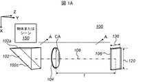
図1Aは、そのような屈曲式カメラの一例である屈曲式カメラ100を概略的に示す等角図である。カメラ100は、上部(入射)面102a、前方(出射)面102b、および光屈折面(反射面)102cを有するプリズム102、レンズ104および撮像素子106を含む。プリズム102(および本明細書に記載されている他のすべてのプリズム)は典型的には、ガラス、プラスチックなどの光を透過する材料から作製される。反射面102cは典型的には、光の大部分(90%を超える、または99%を超える、または99.9%を超える)が表面で反射するような反射材料(例えば、金属または誘電体)で覆われる。入射面102aおよび出射面102bに到達する光は、若干の反射を伴って通過し得る。入射面102aおよび出射面102bに到達する光は、プリズムの透明な材料および空気の屈折率の変化に起因した若干の反射を伴うこともあり、また、特にいくつかの場合において、当該技術分野で公知のように全内部反射(total internal reflection(TIR))が起こることもある。レンズ104は、焦点長f、クリアアパーチャ(CA)、および光軸108を有する数学的単一要素レンズとして示されている。撮像素子106は、高さ120および幅130によって特徴付けられる。第1の光路からX方向に沿って(例えば、物体またはシーン150から)到達する光は、プリズム102によって、Y方向に沿って第2の光路に、すなわちレンズ104に、次いで撮像素子106に、向け直される(屈折する)。プリズム102は、光軸108に平行なY方向における入射面102aに沿ったプリズム長と、X方向における出射面102bに沿ったプリズム高とを有する。カメラ100は以下に定義されるように、フルカメラ視野を有する。 FIG. 1A is an isometric view schematically showing a
カメラ100(および以下のすべての他のカメラの実施形態)は例えば、シールド、すべての要素をまとめて保持するためのシャーシ、焦点合わせおよび光学画像安定化を可能にする作動機構、配線、撮像素子をカメラのホストに接続するためのコネクタなど(ただし、これらに限定されない)、図示されていない他の部品を有していてもよい。さらに、他の光学素子(例えば、レンズ、ミラー、プリズム)が追加されてもよく、本明細書で提示するすべての解析は、そのような素子にも適用されるものとする。カメラ100(および以下のすべての他のカメラの実施形態)は、携帯電話、ラップトップ、コンピュータ、タブレット、車両(自動車、自動二輪車、トラックなど)、テレビ、スマートスピーカ、ロボット、無人機、飛行無人機などの様々なデバイスの一部とする(にホストされる)ことができる。カメラ100(および以下の全ての他のカメラの実施形態)は、別のカメラ(屈曲式または非屈曲式)と一体化されて、デュアルカメラを形成することができる。 The camera 100 (and all other camera embodiments described below) includes, for example, a shield, a chassis to hold all elements together, an actuation mechanism to enable focusing and optical image stabilization, wiring, and an image sensor. May be provided with other components not shown, such as (but not limited to) a connector for connecting the camera to a camera host. Further, other optical elements (eg, lenses, mirrors, prisms) may be added, and all analyzes presented herein shall also apply to such elements. The camera 100 (and all other camera embodiments described below) can be mobile phones, laptops, computers, tablets, vehicles (automobiles, motorcycles, trucks, etc.), televisions, smart speakers, robots, drones, flying unmanned. It can be part of (hosted on) a variety of devices, such as machines. Camera 100 (and all other camera embodiments described below) can be integrated with another camera (flexible or non-flexible) to form a dual camera.
図1Aに示される座標系は、全ての図について当てはまる。X方向は第2の光路に平行であり、Y方向は第1の光路に平行であり、Z方向はX−Y平面に垂直である。 The coordinate system shown in FIG. 1A is true for all figures. The X direction is parallel to the second optical path, the Y direction is parallel to the first optical path, and the Z direction is perpendicular to the XY plane.
本明細書で使用されるように、「上部」または「上方」という用語は、X方向において物体またはシーン150により近くかつその物体またはシーン150に面する屈曲式カメラの側面を指し、一方、「底部」、「下」または「下部」という用語は、撮像された物体またはシーン150からX方向において最も遠くかつその物体またはシーン150からみて外方に向いている屈曲式カメラの側面を指す。本明細書で使用する「背面」という用語は、Y方向において屈曲式カメラの撮像素子106から最も遠い側を指し、一方、「正面」という用語は、Y方向において屈曲式カメラの撮像素子106に最も近い側を指す。本明細書で使用する場合、長さは第2の光路(Y方向)に沿って測定され、高さは第1の光路(X方向)に沿って測定され、深さはZ方向に沿って測定される。 As used herein, the terms “upper” or “above” refer to the side of an articulated camera that is closer to and faces an object or
図1Bは、100’と番号付けされた屈曲式カメラ(または単にカメラ)の別の例を概略的に示す。カメラ100’は、単一要素レンズ104がレンズアセンブリ(単に「レンズ」とも呼ばれる)104’に置き換えられていることを除いて、カメラ100と同様である。レンズアセンブリ104’は、共通の光軸108を有する複数の(この場合、例えば、4つの)レンズ素子を含む。この場合、レンズアセンブリ104’は、物体側から第1のレンズ素子L1のクリアアパーチャと、一定の有効焦点距離(effective focal length(EFL))とを備え得る。EFLはfに置き換えられる。EFLは、レンズアセンブリ104’によって単一のレンズ素子に与えられる倍率の数学的等価物である。以下の解析は、多重レンズ素子の場合に適用される。なお、レンズ素子の数は図示された4つとは異なってもよく、例えば、4と7との間の任意の数であってもよい。複数のレンズ要素からなるレンズの構造および設計は当技術分野で知られており、例えば、共有に係る米国特許第9392188号を参照されたい。 FIG. 1B schematically illustrates another example of a flex camera (or simply a camera) numbered 100 '. Camera 100 'is similar to
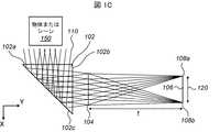
図1Cは、図1Aに見られる切断線A−Aに沿った屈曲式カメラ100の断面における光線軌跡図を示す。切断は、レンズ104の中心、すなわち光軸108を通過する。光線軌跡図は、プリズム102に入ってレンズ104に進み、撮像素子106で終わるいくつかの画像形成光線110の軌道を示す。図1Cでは、撮像素子106上の2つの最端点106aおよび106bに到達する光線の軌道のみが示されている。以下の図(1D−1F、2A−C、3A−C、4、5A−B、および6A)は、切断された側面からの様々な屈曲式カメラを光線追跡とともに示す。これらの図では、進歩性を強調するために、選択された数の光線のみが表示される。これらの図はすべて、図示されていない深さを有する3次元(3D)カメラおよび光線の関わり合いを当業者が理解することができるように、例示的な2次元の切断である。 FIG. 1C shows a ray trajectory diagram in a cross section of the
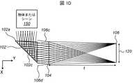
カメラのサイズの制限、特にカメラの高さの問題(X方向の第1の光路に沿って測定される高さ)に起因して、多くの場合、屈曲式カメラのプリズムは小型化されたサイズ(すなわち、より小さい入射面および出射面)を有する。そのため、フルカメラ視野内における全ての光線がプリズムに入ってレンズおよびセンサに向けて反射されるわけではない。図1Dは、プリズム102’が図1A〜1Cのプリズム102よりも低い高さを有する例を示す。その結果、108aおよび108bとマークされた潜在的に画像を形成する光線の一部は、物体からプリズムを通ってレンズに到達することができない。そのような場合、迷光(stray light(SL))は以下に説明するように、プリズムからレンズに入射することができる。図1Dでは、画像から物体に向かう画像形成光線により、フルカメラ視野が示されている。定義によれば、フルカメラ視野は、カメラを出る全ての光線の延伸を含む。図1Dは、プリズム102’がフルカメラ視野内に存在する(すなわち、交差する)ことを示す。 Due to camera size limitations, especially camera height issues (heights measured along the first optical path in the X direction), the prisms of articulated cameras often have a reduced size. (Ie, smaller entrance and exit surfaces). As such, not all light rays in the full camera field of view enter the prism and are reflected toward the lenses and sensors. FIG. 1D shows an example where the
以下の全ての図において、実線は画像形成光線を示し、破線はSL光線を示す。 In all of the following figures, solid lines indicate image forming rays and broken lines indicate SL rays.
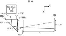
図1Eは、プリズムがフルカメラ視野と交差する屈曲式カメラにおいて生じる1つの問題を概略的に示す。画像形成光線110のような大部分の光線は、プリズム102’によって屈折してレンズ104を通過し、撮像素子106上に画像を形成する。一方、漂遊光線112のような若干の光線は、撮像素子に到達することを防ぐ必要があるSL光線である。プリズムでは、光線がプリズム内で内部反射してレンズに入射する場合に、SLの特殊なケースが存在することがある。そのような光線は、二重反射(ひとつは反射面102cでの反射であり、もうひとつは入射面102aおよび/または出射面102bのような別の面での反射である)を行う。図1Eに示す場合、漂遊光線112は、入射面102aを通ってプリズム102’に入り、最初に出射面102bで反射し、次に反射面102cで反射し、出射面102bを通って出射し、レンズ104および撮像素子106に到達する。すなわち、光線112は、光線110に対して出射面102bでの1つの余分な反射を有する。漂遊光線112のような光線は、タイプ1の「二重反射SL」(DRSL)であると考えられ得る。 FIG. 1E schematically illustrates one problem that occurs in a flex camera where the prism intersects the full camera field of view. Most light rays, such as image forming
図1Fは、屈曲式カメラに関する別の問題を概略的に示す。図1Fに示す場合、漂遊光線114は、入射面102aを通ってプリズム102’に入射し、最初に反射面102cで反射し、次いで入射面102aで反射し、出射面102bを通って出射し、レンズ104および撮像素子106に到達する。すなわち、光線114は、光線110に対して入射面102aでの1つの余分な反射を有する。図1Fに見られる漂遊光線114のような光線は、タイプ2のDRSLであると考えられ得る。 FIG. 1F schematically illustrates another problem with a flex camera. In the case shown in FIG. 1F,
定義:
「フルレンズアパーチャ」:光学的に使用可能な第1のレンズ素子の物体側の最大の表面(すなわち、レンズの公式によって定義される、たるみを有するすべての表面)の形状およびサイズを有する開口。たるみは、面頂点からの表面変位の光軸要素である。Definition:
"Full lens aperture": an aperture having the shape and size of the object-side largest surface of the optically usable first lens element (i.e., all surfaces with sag, as defined by the lens formula). The sag is the optical axis element of the surface displacement from the surface vertex.
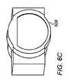
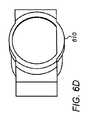
「実際のレンズアパーチャ」:入射光線に開口する、すなわち、鏡筒によって遮断されない、第1のレンズ素子の物体側の表面の形状およびサイズを有する開口。実際のレンズアパーチャは、フルレンズアパーチャに非常に近い(すなわち、実質的に同じ形状およびサイズである)か、または鏡筒がフルレンズアパーチャのかなりの面積を遮断するように設計されている場合、フルレンズアパーチャよりも小さくすることができる。後者の場合(「遮断されたレンズアパーチャ」とも呼ばれる)、実際のレンズアパーチャはフルレンズアパーチャとは異なる形状を有し得る。例えば、フルレンズアパーチャは円形であり、遮断されたレンズアパーチャはDカット円(すなわち、1つ以上の弦によって切断された円形開口)の形状(例えば、図6C〜Eを参照)を有する可能性がある。 “Actual lens aperture”: an aperture that is open to the incident light beam, ie, has the shape and size of the object-side surface of the first lens element that is not blocked by the barrel. The actual lens aperture is very close to (i.e., substantially the same shape and size of) the full lens aperture, or if the barrel is designed to block a significant area of the full lens aperture, It can be smaller than the full lens aperture. In the latter case (also called "blocked lens aperture"), the actual lens aperture may have a different shape than the full lens aperture. For example, the full lens aperture may be circular, and the blocked lens aperture may have the shape of a D-cut circle (i.e., a circular opening cut by one or more chords) (see, for example, FIGS. 6C-E). There is.
「フルカメラ視野」:フルレンズアパーチャおよび画像平面に衝突して画像を形成することができる、物体空間内のすべての光線の位置および方向によって形成される円錐状の幾何学的形状。フルカメラ視野は、レンズの焦点距離、レンズのクリアアパーチャ、およびセンサの寸法の組合せによって決定される。円錐状の形状は、レンズのクリアアパーチャと交差し、その接線角度は、センサの寸法をレンズ焦点距離で割ることにより決定される。 "Full camera field of view": The conical geometry formed by the position and direction of all rays in object space that can strike the full lens aperture and image plane to form an image. The full camera field of view is determined by a combination of the focal length of the lens, the clear aperture of the lens, and the dimensions of the sensor. The conical shape intersects the clear aperture of the lens and its tangent angle is determined by dividing the sensor dimensions by the lens focal length.
「遮断されたカメラ視野」:遮断されたレンズアパーチャおよび画像平面に衝突して画像を形成することができる、物体空間内のすべての光線の位置および方向によって形成される円錐状の幾何学的形状。 "Occluded camera field of view": A conical geometry formed by the position and direction of all rays in object space that can strike the occluded lens aperture and image plane to form an image. .
様々な実施形態において提供される屈曲式カメラは、レンズ光軸を有するレンズと、撮像素子と、第1の光路から撮像素子に向かう第2の光路へ光を屈折させるプリズムとを有し、第2の光路はレンズ光軸に沿っており、屈曲式カメラはフルカメラ視野を有し、プリズムはフルカメラ視野と交差し、屈曲式カメラは二重反射迷光(DRSL)が撮像素子に到達するのを防止する構造を有する。 A bending camera provided in various embodiments includes a lens having a lens optical axis, an image sensor, and a prism that refracts light from a first optical path to a second optical path toward the image sensor. The optical path of 2 is along the lens optical axis, the bent camera has a full camera field of view, the prism intersects the full camera field of view, and the bent camera has a double reflected stray light (DRSL) reaching the image sensor. It has a structure to prevent
例示的な実施形態では、DRSLが撮像素子に到達するのを防止するためのカメラ構造は、レンズとプリズムとの間に配置された遮光要素を含む。 In an exemplary embodiment, a camera structure for preventing DRSL from reaching the imager includes a light blocking element disposed between the lens and the prism.
いくつかの例示的な実施形態では、DRSLが撮像素子に到達するのを防止するためのカメラ構造は、プリズムの底部に形成されたファセットを含み、ファセットはDRSLタイプ1の光線が撮像素子に到達するのを防止するのに十分な長さを有する。一実施形態では、プリズムの底部に形成されたファセットは、DRSLタイプ3の光線が撮像素子に到達するのを防止するように傾斜される。一実施形態では、プリズムの底部に形成されたファセットは、不透明なマスクで覆われる。 In some exemplary embodiments, a camera structure for preventing DRSL from reaching the imager includes a facet formed at the bottom of the prism, where the facet is such that DRSL type 1 light rays reach the imager. Be long enough to prevent In one embodiment, the facets formed at the bottom of the prism are tilted to prevent DRSL type 3 rays from reaching the imager. In one embodiment, the facets formed at the bottom of the prism are covered with an opaque mask.
例示的な実施形態では、DRSLが撮像素子に到達するのを防止するためのカメラ構造は、プリズムの入射(上部)面および/または出射面に配置されたカバーを含む。 In an exemplary embodiment, a camera structure for preventing DRSL from reaching the imager includes a cover located on the entrance (top) and / or exit surface of the prism.
いくつかの例示的な実施形態では、DRSLが撮像素子に到達するのを防止するためのカメラ構造は、プリズムに形成された側面ファセットを含む。一実施形態では、側面ファセットは、DRSLタイプ2の光線が撮像素子に到達するのを防止するように傾斜される。一実施形態では、側面ファセットは、不透明なマスクで覆われる。 In some exemplary embodiments, a camera structure for preventing DRSL from reaching the imager includes side facets formed in a prism. In one embodiment, the side facets are sloped to prevent DRSL type 2 light rays from reaching the imager. In one embodiment, the side facets are covered with an opaque mask.
例示的な実施形態では、DRSLが撮像素子に到達するのを防止するためのカメラ構造は、プリズムに形成された傾斜した底面ファセットを含む。 In an exemplary embodiment, a camera structure for preventing DRSL from reaching the imager includes an inclined bottom facet formed in a prism.
いくつかの実施形態では、プリズムは遮断された視野と交差しない。いくつかのそのような実施形態では、レンズは円形のフルレンズアパーチャを有し、実際のレンズアパーチャはDカット円形状を有する。 In some embodiments, the prism does not intersect the occluded field of view. In some such embodiments, the lens has a circular full lens aperture and the actual lens aperture has a D-cut circular shape.
様々な実施形態では、レンズ光軸を有するレンズと、撮像素子と、第1の光路から撮像素子に向かうレンズ光軸に沿った第2の光路へ光を屈折させるプリズムとを含む屈曲式カメラを提供するステップであって、カメラはフルカメラ視野を有し、プリズムはフルカメラ視野と交差するステップと、DRSLが撮像素子に到達することを防止するように屈曲式カメラを構成するステップとを含む方法が提供される。 In various embodiments, a bendable camera that includes a lens having a lens optical axis, an imager, and a prism that refracts light into a second optical path along the lens optical axis from the first optical path toward the imager. Providing, the camera having a full camera field of view, wherein the prism intersects the full camera field of view, and configuring the articulated camera to prevent the DRSL from reaching the image sensor. A method is provided.
例示的な実施形態では、DRSLが撮像素子に到達するのを防止するように屈曲式カメラを構成するステップは、レンズとプリズムとの間に遮光要素を配置するステップを含む。 In an exemplary embodiment, configuring the bendable camera to prevent the DRSL from reaching the imager includes placing a light blocking element between the lens and the prism.
いくつかの例示的な実施形態では、DRSLが撮像素子に到達するのを防止するように屈曲式カメラを構成するステップは、プリズムの底部に形成されたファセットを形成するステップを含み、ファセットはDRSLタイプ1の光線が撮像素子に到達するのを防止するのに十分な長さを有する。一実施形態では、プリズムの底部に形成されたファセットは、DRSLタイプ3の光線が撮像素子に到達するのを防止するように傾斜される。 In some exemplary embodiments, configuring the bend camera to prevent the DRSL from reaching the imager includes forming a facet formed at the bottom of the prism, wherein the facet is a DRSL It has a length sufficient to prevent Type 1 light rays from reaching the image sensor. In one embodiment, the facets formed at the bottom of the prism are tilted to prevent DRSL type 3 rays from reaching the imager.
例示的な実施形態では、DRSLが撮像素子に到達するのを防止するように屈曲式カメラを構成するステップは、プリズムの入射面および/または出射面にカバーを配置するステップを含む。 In an exemplary embodiment, configuring the bendable camera to prevent the DRSL from reaching the imager includes placing a cover on the entrance and / or exit surfaces of the prism.
例示的な実施形態では、DRSLが撮像素子に到達するのを防止するように屈曲式カメラを構成するステップは、プリズムに傾斜した側面ファセットを形成するステップを含む。 In an exemplary embodiment, configuring the bend camera to prevent the DRSL from reaching the imager includes forming inclined side facets on the prism.
様々な実施形態では、プリズムは、遮断された視野と交差しない。いくつかのそのような実施形態では、レンズは円形のフルレンズアパーチャを有し、実際のレンズアパーチャはDカット円形状を有する。 In various embodiments, the prism does not intersect the occluded field of view. In some such embodiments, the lens has a circular full lens aperture and the actual lens aperture has a D-cut circular shape.
本明細書に開示される実施形態の非限定的な例は、この段落の後に列挙される、本明細書に添付される図面を参照して、以下に記載される。図面および説明は、本明細書に開示された実施形態を明確にし、理解を容易にすることを意図しており、決して限定するものと考えるべきではない。異なる図面における同様の要素は、同じ符号によって示されてもよい。
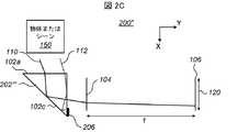
図2Aは、200と番号付けされた屈曲式カメラの実施形態の一例を概略的に示す。この実施形態および以下の実施形態では、屈曲式カメラは、フルカメラ視野と、そのフルカメラ視野と交差するプリズムとを有する。カメラ200は、タイプ1のDRSLが撮像素子106に到達するのを防止する構造を有する。本明細書で使用される「カメラ構造」という用語は、カメラの構造要素およびそれらの配置を指す。本明細書で使用されるように、「DRSLを防止する」という語は、「DRSLを低減および/または完全に排除する」ことを意味する。この例では、プリズム202’は、(プリズム102’に対して)追加された底面ファセットまたは「面」202を有し、これにより、漂遊光線112が、反射面102cでの2回目の反射の前にプリズムから出ることが可能になる。底面ファセット202は、反射面102cと出射面102bとの間、すなわちプリズム202’の底部に追加される。例示的には、底面ファセット202は、漂遊光線112のような光線の90%(または99%)がファセット202を通ってプリズム202’から出射することにより撮像素子106に到達しない場合に、DRSLタイプ1の光線が撮像素子に到達するのを防止するのに十分な長さを有すると言われる。底面ファセット202は、漂遊光線112が遮断されるように、不透明なマスクまたは材料(図示せず)によって任意に覆われてもよい。例えば、底面ファセット202は、入射面102aの長さ(光軸の方向に沿ったY方向の長さ)の5%〜10%の長さを有していてもよい。底面202は、Z方向(X−Y平面に垂直)に入射面102aと同じ深さを有していてもよい。 FIG. 2A schematically illustrates an example of an embodiment of a flex camera numbered 200. FIG. In this and the following embodiments, the articulated camera has a full camera field of view and a prism that intersects the full camera field of view. The
図2Bは、タイプ1のDRSLが撮像素子106に到達するのを防止する構造を有する、200’と番号付けされた屈曲式カメラの実施形態の別の例を概略的に示す。この例では、プリズム202’’は、入射面102aの前方側に形成された、または取り付けられた追加の遮光材料またはカバー204(例えば、ブラックマスク)を含む。カバー204は例えば、不透明材料の蒸着、接着、または取り付けによって形成することができる。カバー204は、漂遊光線112がプリズム202’’に入るのを阻止する。カバーは、タイプ1のDRSLを効率的に防止するために、適切な形状およびサイズ(例えば、所与の長さおよび幅のストライプの形態)を有し得る。例えば、カバー204は入射面102aの(Y方向の)長さの5%〜10%の幅を有し、Z方向の入射面102aの深さと同じ深さであってもよい。 FIG. 2B schematically illustrates another example of a flex camera embodiment numbered 200 'having a structure that prevents Type 1 DRSL from reaching the
図2Cは、タイプ1のDRSLが撮像素子106に到達するのを防止する構造を有する、200’’と番号付けされた屈曲式カメラの実施形態のさらに別の例を概略的に示す。この例では、プリズム202’’’は、出射面102bの底部において漂遊光線112がプリズムから出射するのを遮断する追加のカバー206を有する。カバー206は、材料、構成、および寸法に関して、カバー204と同様であってもよい。例えば、カバー206は、出射面102bの(X方向の)高さの5%〜10%の幅を有してもよく、Z方向の出射面102bと同じ深さであってもよい。 FIG. 2C schematically illustrates yet another example of a flex camera embodiment numbered 200 ″ having a structure that prevents Type 1 DRSL from reaching the
要約すると、3つのカメラの実施形態200、200’および200’’のいずれも、漂遊光線112がレンズおよび撮像素子に到達するのを防止する構造を有する。 In summary, all three
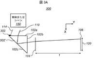
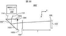
図3Aは、タイプ2のDRSLが撮像素子106に到達するのを防止する構造を有する屈曲式カメラ300の実施形態の一例を概略的に示す。この例では、プリズム302’は、入射面102aの後方側に、漂遊光線110のプリズムへの入射を遮断するカバー302を有する。図3Bは、タイプ2のDRSLが撮像素子106に到達するのを防止する構造を有する、300’と番号付けされた屈曲式カメラの実施形態の別の例を概略的に示す。この例では、プリズム302’’は、出射面102bの上側に、漂遊光線114がプリズムから出射するのを遮断する追加のカバー(例えば、ブラックマスク)304を有する。図3Cは、タイプ2のDRSLが撮像素子106に到達するのを防止する構造を有する、300’’と番号付けされた屈曲式カメラの実施形態の別の例を概略的に示す。この例では、プリズム302’’’は、入射面102aと反射面102cとの間に付加された側面ファセット306を有する。ファセット306は、入射面、出射面、および反射面(102a〜c)のすべてまたはいくつかに対して傾斜していてもよく、すなわち、これらの面のいずれにも平行でなくてもよい。漂遊光線114は、反射面102cに到達する前に側面ファセット306に到達する。しかし、側面306からの反射は起こり得る。従って、側面ファセット306は、漂遊光線114が撮像素子106に到達しないような角度で反射されるように傾斜していてもよい。ファセット306の傾斜角は、入射面102aに対して1〜10度であってもよい。例えば、側面ファセット306は、出射面102bの(X方向の)高さの5%〜10%の高さを有していてもよい。 FIG. 3A schematically illustrates an example of an embodiment of a
有利には、側面ファセット306は、漂遊光線114が遮断されるように、不透明なマスクまたは材料(図示せず)によって任意選択で覆われてもよい。 Advantageously, the
ファセット306並びにカバー302および304の、材料、形成プロセスおよび/または寸法は、ファセット202並びにカバー204および206の、材料、形成プロセスおよび/または寸法と同様であってもよい。 The material, forming process and / or dimensions of
要約すると、図3A〜図3Cを参照して説明した3つのカメラの実施形態のいずれかを使用すると、漂遊光線114はレンズおよび撮像素子に到達しない。 In summary, using any of the three camera embodiments described with reference to FIGS. 3A-3C, stray
図2Aに見られるように、プリズム202’の底面ファセット202は、SL問題を解決することができる。底面ファセット202はまた、プリズムの高さを低減することができ、このことは、SLの問題にかかわらず、所望される解決策である。しかし、底面ファセット202は、新しいタイプのDRSLを導入する場合がある。図4は、底面ファセット202を有するプリズムにおける漂遊光線116の軌跡を示す。図4に示す場合、漂遊光線116、は入射面102aを通ってプリズムに入り、最初に反射面102cで反射し、次に底面ファセット202で反射し、出射面102bを通って出射し、レンズ104および撮像素子106に到達する。すなわち、光線116は、光線110に対して底面ファセット202での1つの余分な反射を有する。図4に見られる漂遊光線116のような光線は、タイプ3のDRSLであると考えられる。 As seen in FIG. 2A, the
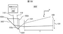
図5Aは、タイプ3のDRSLが撮像素子106に到達するのを防止する構造を有する、屈曲式カメラ500の実施形態一例を概略的に示す。この例では、プリズム502’は出射面102bに、漂遊光線116がプリズムから出射するのを遮断する追加のカバー(例えば、ブラックマスク)502を有する。例えば、カバー502は、出射面102bの(X方向の)長さの5%〜10%の幅を有し、Z方向の出射面102bの深さと同じ深さであってもよい。図5Bは、タイプ3のDRSLが撮像素子106に到達するのを防止する構造を有する、500’と番号付けされた屈曲式カメラの実施形態の別の例を概略的に示す。この例では、プリズム502’’では、傾斜した底面ファセット504が底面ファセット202と置き換わり、漂遊光線116が撮像素子106に到達しない角度で反射されるように傾斜している。傾斜した底面ファセット504は、入射面および反射面(102a、c)のすべてまたはいくつかに対して傾斜しており、すなわち、これらの面のいずれにも平行ではない。傾斜した底面ファセット504の寸法は例えば、側面ファセット306の寸法と同様とすることができ、一方、入射面102aに対する傾斜角は、Y軸から1〜10度とすることができる。 FIG. 5A schematically illustrates an exemplary embodiment of a
要約すると、上記の7つの屈曲式カメラの実施形態は、二重反射迷光(DRSL)が撮像素子に到達するのを防止する構造を有する。 In summary, the seven bending camera embodiments described above have a structure that prevents double reflected stray light (DRSL) from reaching the image sensor.
すべてのDRSL問題に対する別の任意の解決策は、レンズ104のCAの遮断を使用することができる。上述したように、DRSLは、レンズのCAに依存するフルカメラ視野をプリズムが覆わない場合に起こり得る。より小さいCAは、より小さいフルカメラ視野をもたらし、したがってプリズムは、それを覆うことができる。図6Aは、カメラ100’と同様の屈曲式カメラ600(と光線追跡)の実施形態を示し、レンズ104は、より小さいCAを有するレンズ604に置き換えられている。この場合、プリズム102’は、フルカメラ視野を覆う。しかしながら、レンズに入射する光量の低下およびレンズのf値の増加のために、CAの低下は典型的には望ましくない(f値は、光学系における既知の用語であり、レンズ焦点距離とCA直径の比である)。 Another optional solution to all DRSL problems may use blocking of the CA of the
図6Bは、フルレンズアパーチャおよびCA606を有するレンズアセンブリ604の例を示す。図6C〜図6Eは、レンズのクリアアパーチャが、軸対称ではなく、すなわちレンズのCAの上部(608)および/または底部(610)を遮断することによって、遮断される鏡筒の実施形態を示す。図6C〜6Eで提供される遮断は、レンズのCAを縮小させる解決策と比較して、フルカメラ視野を縮小し、レンズに入る光量の低下をより少なくすることを可能にする。したがって、ブロック部608および/または610を使用して、漂遊光線112若しくは114のようなタイプ1のDRSLおよび/または漂遊光線116のようなタイプ3のDRSLを遮断することができる。 FIG. 6B shows an example of a
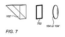
図7は、クリアアパーチャを遮断するための別の選択肢を示す。図7において、マスク702のような遮光要素は、カメラ視野を遮断するために使用され、従って、遮断されたカメラ視野を引き起こす。マスク702の使用は、漂遊光線112若しくは114のようなタイプ1のDRSLおよび/または漂遊光線116のようなタイプ3のDRSLを阻止することができる。 FIG. 7 shows another option for blocking the clear aperture. In FIG. 7, a light blocking element, such as a
一般に、タイプ1、2、または3のDRSLは、同じプリズム内で生じ得る。図2A〜C、3A〜C、5A〜C、6B〜6Eおよび7に見られる全ての解決策(遮断の特徴)は、DRSLを減少または排除するために、同時にまたは任意の組み合わせで使用され得る。 In general, Type 1, 2, or 3 DRSLs can occur in the same prism. All the solutions (blocking features) found in FIGS. 2A-C, 3A-C, 5A-C, 6B-6E and 7 can be used simultaneously or in any combination to reduce or eliminate DRSL .
サイドカットからのプリズムを示すすべての図(図1C〜1F、2A〜2C、3A〜3C、4、5A〜B、6A)は例示的に、同じ深さのすべての面およびファセット(Z方向に沿って測定され、第1および第2の光路に垂直である)を有していてもよい。サイドカットからのプリズムを示すすべての図(図1C〜1F、2A〜2C、3A〜3C、4、5A〜B、6A)は例示的に、同じ深さではないすべての面およびファセット(Z方向に沿って測定され、第1および第2の光路に垂直である)を有していてもよく、すなわち、様々な深さを有する面およびファセットを有していてもよい。 All figures showing the prism from the side cut (FIGS. 1C-1F, 2A-2C, 3A-3C, 4, 5A-B, 6A) are illustratively all the faces and facets of the same depth (in the Z direction). (Measured along and perpendicular to the first and second optical paths). All figures showing the prism from the side cut (FIGS. 1C-1F, 2A-2C, 3A-3C, 4, 5A-B, 6A) are illustratively all surfaces and facets that are not the same depth (Z-direction). And perpendicular to the first and second optical paths), i.e., may have surfaces and facets with varying depths.
特に明記しない限り、選択のためのオプションのリストの最後の2つのメンバ間の「および/または」という表現の使用は、リストされたオプションのうちの1つまたは複数の選択が適切であり、可能であることを示す。 Unless otherwise stated, the use of the term "and / or" between the last two members of a list of options for a selection is appropriate where the selection of one or more of the listed options is appropriate It is shown that.
特許請求の範囲または明細書が「a」または「an」の要素に言及する場合、そのような言及は、その要素のうちの1つだけが存在すると解釈されるべきではないことを理解されたい。 When a claim or specification refers to an "a" or "an" element, it is to be understood that such reference is not to be construed as only one of the element being present. .
本明細書において言及される全ての参考文献は、それぞれの個々の参考文献があたかも、参考として本明細書に組み込まれるように具体的かつ個別に示されるかのように、その全体が本明細書に参考として組み込まれる。さらに、本出願における任意の参考文献の引用または識別は、そのような参考文献が本発明の先行技術として利用可能であることを容認するものと解釈されるべきではない。 All references mentioned herein are incorporated by reference in their entirety, as if each individual reference was specifically and individually indicated to be incorporated herein by reference. Incorporated by reference. Furthermore, citation or identification of any reference in this application shall not be construed as an admission that such reference is available as prior art to the present invention.
Claims (22)
Translated fromJapanesea)レンズ光軸を有するレンズと、
b)撮像素子と、
c)光を第1の光路から前記撮像素子に向かう前記レンズ光軸に沿った第2の光路に屈折させるプリズムとを有し、
当該屈曲式カメラは、フルカメラ視野を有し、
前記プリズムは前記フルカメラ視野と交差し、
当該屈曲式カメラは、二重反射迷光(DRSL)が前記撮像素子に到達するのを防止するカメラ構造を有する
ことを特徴とする屈曲式カメラ。A bendable camera,
a) a lens having a lens optical axis;
b) an image sensor;
c) a prism for refracting light from a first optical path to a second optical path along the optical axis of the lens toward the image sensor,
The bending camera has a full camera field of view,
The prism intersects the full camera field of view,
The bending camera has a camera structure for preventing double reflection stray light (DRSL) from reaching the image sensor.
b)二重反射迷光(DRSL)が前記撮像素子に到達するのを防止するように前記屈曲式カメラを構成するステップと、
を有する方法。a) A bending camera including a lens having a lens optical axis, an image sensor, and a prism for refracting light from a first optical path to a second optical path along the lens optical axis toward the image sensor. Wherein the articulated camera has a full camera field of view and the prism intersects the full camera field of view;
b) configuring the bendable camera to prevent double reflected stray light (DRSL) from reaching the imager;
Having a method.
14. The method of claim 13, wherein the lens has a circular full lens aperture, and the actual lens aperture has a D-cut circular shape.
Applications Claiming Priority (3)
| Application Number | Priority Date | Filing Date | Title |
|---|---|---|---|
| US201762529496P | 2017-07-07 | 2017-07-07 | |
| US62/529,496 | 2017-07-07 | ||
| PCT/IB2018/054928WO2019008517A1 (en) | 2017-07-07 | 2018-07-03 | Folded camera prism design for preventing stray light |
Publications (1)
| Publication Number | Publication Date |
|---|---|
| JP2020509420Atrue JP2020509420A (en) | 2020-03-26 |
Family
ID=64949810
Family Applications (1)
| Application Number | Title | Priority Date | Filing Date |
|---|---|---|---|
| JP2019547380APendingJP2020509420A (en) | 2017-07-07 | 2018-07-03 | Bend camera prism design to prevent stray light |
Country Status (6)
| Country | Link |
|---|---|
| US (1) | US11106018B2 (en) |
| EP (1) | EP3461284A4 (en) |
| JP (1) | JP2020509420A (en) |
| KR (1) | KR20190022522A (en) |
| CN (1) | CN109564337A (en) |
| WO (1) | WO2019008517A1 (en) |
Families Citing this family (35)
| Publication number | Priority date | Publication date | Assignee | Title |
|---|---|---|---|---|
| KR101634516B1 (en) | 2013-06-13 | 2016-06-28 | 코어포토닉스 리미티드 | Dual aperture zoom digital camera |
| JP2016523389A (en) | 2013-07-04 | 2016-08-08 | コアフォトニクス リミテッド | Compact telephoto lens assembly |
| US9857568B2 (en) | 2013-07-04 | 2018-01-02 | Corephotonics Ltd. | Miniature telephoto lens assembly |
| US9392188B2 (en) | 2014-08-10 | 2016-07-12 | Corephotonics Ltd. | Zoom dual-aperture camera with folded lens |
| CN112433331B (en) | 2015-01-03 | 2022-07-08 | 核心光电有限公司 | Miniature telephoto lens module and camera using the same |
| EP3809685A4 (en)* | 2018-06-12 | 2021-09-01 | Ningbo Sunny Opotech Co., Ltd. | CAMERA UNIT WITH LIGHT DEFLECTION MECHANISM AND ITS APPLICATION |
| US11336830B2 (en) | 2019-01-03 | 2022-05-17 | Corephotonics Ltd. | Multi-aperture cameras with at least one two state zoom camera |
| WO2021033047A1 (en) | 2019-08-21 | 2021-02-25 | Corephotonics Ltd. | Low total track length for large sensor format |
| EP4030233B1 (en)* | 2019-09-18 | 2025-05-07 | Ningbo Sunny Opotech Co., Ltd. | Periscopic camera module and electronic device |
| US12072609B2 (en) | 2019-09-24 | 2024-08-27 | Corephotonics Ltd. | Slim pop-out cameras and lenses for such cameras |
| KR102392164B1 (en)* | 2020-01-17 | 2022-04-29 | 삼성전기주식회사 | Reflection module and camera module including the same |
| US11363176B2 (en)* | 2020-01-17 | 2022-06-14 | Samsung Electro-Mechanics Co., Ltd. | Reflection module including a holder and a reflective member and a camera module including a reflection module |
| US11770609B2 (en) | 2020-05-30 | 2023-09-26 | Corephotonics Ltd. | Systems and methods for obtaining a super macro image |
| CN113965669A (en)* | 2020-07-21 | 2022-01-21 | 华为技术有限公司 | Camera module and electronic equipment |
| KR102765964B1 (en) | 2020-07-22 | 2025-02-07 | 코어포토닉스 리미티드 | Folded camera lens design |
| CN119414645A (en) | 2020-07-31 | 2025-02-11 | 核心光电有限公司 | camera |
| KR102539638B1 (en)* | 2020-09-16 | 2023-06-02 | 삼성전기주식회사 | Reflection member and Reflection module including the same |
| EP4127788A4 (en) | 2020-09-18 | 2024-06-19 | Corephotonics Ltd. | Pop-out zoom camera |
| US12271105B2 (en) | 2020-11-05 | 2025-04-08 | Corephotonics Ltd. | Scanning Tele camera based on two prism field of view scanning |
| KR20250008791A (en) | 2020-12-01 | 2025-01-15 | 코어포토닉스 리미티드 | Folded camera with continuously adaptive zoom factor |
| KR102536605B1 (en) | 2020-12-28 | 2023-05-26 | 삼성전기주식회사 | Lens and Optical Imaging System |
| CN117425062A (en) | 2021-01-25 | 2024-01-19 | 核心光电有限公司 | Lens system for compact digital camera |
| WO2022200965A1 (en) | 2021-03-22 | 2022-09-29 | Corephotonics Ltd. | Folded cameras with continuously adaptive zoom factor |
| US12313480B2 (en)* | 2021-06-18 | 2025-05-27 | Corning Incorporated | Prism coupling systems and methods employing light-blocking members |
| KR20240012438A (en) | 2021-06-23 | 2024-01-29 | 코어포토닉스 리미티드 | Compact folded tele camera |
| TWI772185B (en)* | 2021-09-17 | 2022-07-21 | 大陽科技股份有限公司 | Imaging lens driving module and electronic device |
| KR102685591B1 (en) | 2021-09-23 | 2024-07-15 | 코어포토닉스 리미티드 | Large aperture continuous zoom folded telecamera |
| CN120315167A (en) | 2021-12-14 | 2025-07-15 | 核心光电有限公司 | Large aperture compact scan telephoto camera |
| KR20240168938A (en)* | 2022-01-24 | 2024-12-02 | 루메뉴이티, 엘엘씨 | Method and system for high-magnification photography using a reflective polarizer and a faraday rotator |
| US12177552B2 (en)* | 2022-05-27 | 2024-12-24 | Samsung Electronics Co., Ltd. | Folded camera for reducing stray light and electronic device including the same |
| CN115396574B (en)* | 2022-08-18 | 2024-07-05 | Oppo广东移动通信有限公司 | Lens module and electronic equipment |
| WO2024063547A1 (en)* | 2022-09-20 | 2024-03-28 | 삼성전자 주식회사 | Camera module and electronic device comprising same |
| US12386154B2 (en) | 2022-11-21 | 2025-08-12 | Samsung Electro-Mechanics Co., Ltd. | Imaging lens system |
| KR102803451B1 (en)* | 2022-11-21 | 2025-05-07 | 삼성전기주식회사 | Imaging Lens System |
| WO2025095763A1 (en)* | 2023-10-31 | 2025-05-08 | 삼성전자 주식회사 | Camera module and electronic device comprising same |
Citations (6)
| Publication number | Priority date | Publication date | Assignee | Title |
|---|---|---|---|---|
| JP2010164841A (en)* | 2009-01-16 | 2010-07-29 | Sharp Corp | Imaging module, image capturing apparatus and optical equipment |
| JP2011145505A (en)* | 2010-01-15 | 2011-07-28 | Panasonic Corp | Lens barrel |
| JP2012068508A (en)* | 2010-09-24 | 2012-04-05 | Hoya Corp | Photographic optical system and photographic device |
| JP2012068510A (en)* | 2010-09-24 | 2012-04-05 | Hoya Corp | Photographic optical system and photographic device |
| JP2013088697A (en)* | 2011-10-20 | 2013-05-13 | Konica Minolta Advanced Layers Inc | Lens barrel and imaging apparatus |
| WO2017037688A1 (en)* | 2015-09-06 | 2017-03-09 | Corephotonics Ltd. | Auto focus and optical image stabilization with roll compensation in a compact folded camera |
Family Cites Families (139)
| Publication number | Priority date | Publication date | Assignee | Title |
|---|---|---|---|---|
| US2106752A (en)* | 1934-12-03 | 1938-02-01 | Sheet Polarizer Company Inc | Field divider |
| US2354503A (en) | 1941-12-01 | 1944-07-25 | Taylor Taylor & Hobson Ltd | Optical objective of the telephoto type |
| US2378170A (en) | 1943-06-25 | 1945-06-12 | Eastman Kodak Co | Telephoto lens |
| US2441093A (en) | 1946-07-22 | 1948-05-04 | Eastman Kodak Co | Telephoto lens |
| US3388956A (en) | 1963-04-10 | 1968-06-18 | Voigtlaender Ag | Photographic telephoto lenses of high telephoto power |
| DE1447278A1 (en) | 1964-06-20 | 1968-12-19 | Voigtlaender Ag | Tele-anastigmat of medium light intensity with a large telephoto effect |
| US3558218A (en) | 1967-12-01 | 1971-01-26 | Polaroid Corp | Three-element telephoto objective lens |
| JPS5116135B2 (en) | 1972-05-10 | 1976-05-21 | ||
| US3942876A (en) | 1972-09-07 | 1976-03-09 | Ponder & Best, Inc. | Telephoto lens |
| JPS5327421A (en) | 1976-08-26 | 1978-03-14 | Asahi Optical Co Ltd | Small telephotographic lens |
| JPS54157620A (en) | 1978-06-01 | 1979-12-12 | Konishiroku Photo Ind Co Ltd | Photographic telephoto lens |
| JPS55163510A (en) | 1979-06-06 | 1980-12-19 | Nippon Kogaku Kk <Nikon> | Telephoto lens |
| JPS5850509A (en) | 1981-09-21 | 1983-03-25 | Ricoh Co Ltd | small telephoto lens |
| JPS59121015A (en) | 1982-12-28 | 1984-07-12 | Nippon Kogaku Kk <Nikon> | Close-range corrected photographic lens |
| JPS6165212A (en) | 1984-09-07 | 1986-04-03 | Fuji Xerox Co Ltd | Image forming lens of copying machine |
| JPS6370211A (en) | 1986-09-11 | 1988-03-30 | Canon Inc | Optical element made of plastic |
| US5000551A (en) | 1989-06-05 | 1991-03-19 | Nikon Corporation | Zoom lens |
| JPH0659195A (en)* | 1992-08-07 | 1994-03-04 | Fuji Photo Optical Co Ltd | Optical system device for endoscope |
| JP3676524B2 (en) | 1996-10-25 | 2005-07-27 | ペンタックス株式会社 | prism |
| US6147702A (en) | 1998-04-17 | 2000-11-14 | Intel Corporation | Calibration of digital cameras |
| US6195209B1 (en) | 1999-05-04 | 2001-02-27 | U.S. Precision Lens Incorporated | Projection lenses having reduced lateral color for use with pixelized panels |
| JP4278879B2 (en) | 2001-02-27 | 2009-06-17 | 株式会社オートネットワーク技術研究所 | Vehicle periphery visual recognition device |
| JP3503941B2 (en) | 2002-02-04 | 2004-03-08 | 富士写真光機株式会社 | 3-group zoom lens |
| US6924948B2 (en) | 2003-08-21 | 2005-08-02 | Arc Design, Inc. | Multifocal lens system for digital cameras |
| JP4276914B2 (en) | 2003-09-18 | 2009-06-10 | オリンパス株式会社 | Vibration wave linear motor and driving method thereof |
| JP2005134486A (en) | 2003-10-28 | 2005-05-26 | Ricoh Co Ltd | Color image reading lens, color image reading lens unit, color image reading apparatus, and image forming apparatus |
| JP2005173191A (en) | 2003-12-11 | 2005-06-30 | Olympus Corp | Optical path bending optical system |
| JP2005215473A (en) | 2004-01-30 | 2005-08-11 | Sekinosu Kk | Projection lens device |
| US6980379B1 (en) | 2004-07-19 | 2005-12-27 | Microalign Technologies, Inc. | Flat wide-angle objective |
| US9155483B2 (en) | 2004-12-03 | 2015-10-13 | The Invention Science Fund I, Llc | Vision modification with reflected image |
| US7206136B2 (en) | 2005-02-18 | 2007-04-17 | Eastman Kodak Company | Digital camera using multiple lenses and image sensors to provide an extended zoom range |
| JP4794912B2 (en) | 2005-06-02 | 2011-10-19 | キヤノン株式会社 | Zoom lens and imaging apparatus having the same |
| JP2007133096A (en) | 2005-11-09 | 2007-05-31 | Konica Minolta Opto Inc | Imaging optical system, imaging lens device, and digital equipment |
| JP2007219199A (en) | 2006-02-17 | 2007-08-30 | Konica Minolta Opto Inc | Lens unit, imaging device and manufacturing method of lens |
| JP4905653B2 (en) | 2006-03-28 | 2012-03-28 | ペンタックスリコーイメージング株式会社 | Medium telephoto lens system |
| JP2007306282A (en) | 2006-05-11 | 2007-11-22 | Citizen Electronics Co Ltd | The camera module |
| KR100900486B1 (en) | 2006-09-04 | 2009-06-03 | 삼성테크윈 주식회사 | Optical module for imaging device and imaging device having same |
| JP4956343B2 (en) | 2006-09-25 | 2012-06-20 | 富士フイルム株式会社 | Bifocal imaging optical system and imaging device |
| TWI332584B (en) | 2007-04-25 | 2010-11-01 | Largan Precision Co Ltd | Optical lens system for taking image |
| US7918398B2 (en) | 2007-06-04 | 2011-04-05 | Hand Held Products, Inc. | Indicia reading terminal having multiple setting imaging lens |
| JP2008304708A (en) | 2007-06-07 | 2008-12-18 | Konica Minolta Opto Inc | Zoom lens and imaging apparatus |
| TWI351530B (en) | 2007-07-05 | 2011-11-01 | Largan Precision Co Ltd | Inverse telephoto with correction lenses |
| TWI354820B (en) | 2007-08-14 | 2011-12-21 | Largan Precision Co Ltd | Optical lens system for taking image |
| JP4947423B2 (en) | 2007-08-29 | 2012-06-06 | コニカミノルタオプト株式会社 | Imaging lens |
| US7710665B2 (en) | 2007-11-08 | 2010-05-04 | Samsung Electro-Mechanics Co., Ltd. | Imaging optical system |
| TWI361914B (en) | 2007-11-16 | 2012-04-11 | Largan Precision Co Ltd | Optical lens system for taking image |
| JP2009134175A (en) | 2007-11-30 | 2009-06-18 | Olympus Imaging Corp | Image forming optical system |
| CN101821658B (en) | 2007-12-04 | 2014-02-26 | 黑眼睛光学有限公司 | Zoom lens and camera system |
| TWI354821B (en) | 2007-12-18 | 2011-12-21 | Largan Precision Co Ltd | Optical lens system for taking image |
| WO2009084192A1 (en) | 2007-12-28 | 2009-07-09 | Panasonic Corporation | Lens barrel and lens support structure |
| TWI361915B (en) | 2008-02-18 | 2012-04-11 | Largan Precision Co Ltd | Optical lens system for taking image |
| TWI361903B (en) | 2008-02-27 | 2012-04-11 | Largan Precision Co Ltd | Optical lens system for taking image |
| TWI361913B (en) | 2008-02-27 | 2012-04-11 | Largan Precision Co Ltd | Optical lens system for taking image |
| JP2009216941A (en) | 2008-03-10 | 2009-09-24 | Tamron Co Ltd | Bending variable power optical system |
| JP2009258286A (en) | 2008-04-15 | 2009-11-05 | Konica Minolta Opto Inc | Imaging lens, imaging unit, and mobile terminal |
| TWI395992B (en) | 2008-07-25 | 2013-05-11 | Largan Precision Co | Four-piece optical lens system for taking image |
| JP5304117B2 (en) | 2008-09-05 | 2013-10-02 | コニカミノルタ株式会社 | Imaging lens, imaging device, and portable terminal |
| TWI384254B (en) | 2008-10-16 | 2013-02-01 | Largan Precision Co Ltd | Optical lens system for taking image |
| TWI379102B (en) | 2008-11-20 | 2012-12-11 | Largan Precision Co Ltd | Optical lens system for taking image |
| TWI388878B (en) | 2008-12-01 | 2013-03-11 | Largan Precision Co Ltd | Optical lens system for taking image |
| TWI382199B (en) | 2008-12-16 | 2013-01-11 | Largan Precision Co Ltd | Optical lens system for taking image |
| JP5300467B2 (en) | 2008-12-26 | 2013-09-25 | キヤノン株式会社 | Optical system and optical apparatus having the same |
| US7826149B2 (en) | 2008-12-27 | 2010-11-02 | Largan Precision Co., Ltd. | Optical lens system for taking image |
| TWI394979B (en) | 2009-01-22 | 2013-05-01 | Largan Precision Co Ltd | Photographing optical lens assembly |
| TWI406004B (en) | 2009-02-19 | 2013-08-21 | Largan Precision Co Ltd | Imaging optical lens assembly |
| TWI395990B (en) | 2009-05-11 | 2013-05-11 | Largan Precision Co Ltd | Optical lens system for taking image |
| TWI404972B (en) | 2009-06-19 | 2013-08-11 | Largan Precision Co | Optical lens system for taking image |
| TWI401466B (en) | 2009-06-19 | 2013-07-11 | Largan Precision Co | Optical lens system for taking image |
| KR20110002630A (en) | 2009-07-02 | 2011-01-10 | 삼성전자주식회사 | Camera operation method and device of mobile terminal |
| TWI421557B (en) | 2009-07-14 | 2014-01-01 | Largan Precision Co Ltd | Camera lens system |
| DE102009028861B4 (en)* | 2009-08-25 | 2015-03-05 | Trimble Jena Gmbh | Measuring device with reduced amount of stray light and manufacturing method for this |
| US8559118B2 (en) | 2009-11-18 | 2013-10-15 | DigitalOptics Corporation Europe Limited | Fixed focal length optical lens architecture providing a customized depth of focus optical system |
| JP2011128445A (en) | 2009-12-18 | 2011-06-30 | Sony Corp | Zoom lens and image pickup apparatus |
| JP2011138047A (en) | 2009-12-28 | 2011-07-14 | Olympus Imaging Corp | Image pickup apparatus having optical path reflecting zoom lens |
| JP2011141396A (en) | 2010-01-06 | 2011-07-21 | Tamron Co Ltd | Imaging lens, camera module, and imaging apparatus |
| CN102193162A (en) | 2010-03-16 | 2011-09-21 | 大立光电股份有限公司 | Zooming shooting module |
| TWI406027B (en) | 2010-04-08 | 2013-08-21 | Largan Precision Co Ltd | Imaging lens assembly |
| JP5498259B2 (en) | 2010-05-24 | 2014-05-21 | 株式会社タムロン | High magnification zoom lens |
| TWI401485B (en) | 2010-06-10 | 2013-07-11 | Largan Precision Co Ltd | Imaging optical lens assembly |
| TWI434096B (en) | 2010-09-16 | 2014-04-11 | Largan Precision Co Ltd | Optical imaging lens system |
| US20120075518A1 (en)* | 2010-09-29 | 2012-03-29 | Hoya Corporation | Imaging unit |
| TWI435135B (en) | 2010-10-06 | 2014-04-21 | Largan Precision Co Ltd | Optical lens system |
| US8339714B2 (en) | 2010-10-13 | 2012-12-25 | Olympus Imaging Corp. | Zoom lens and imaging apparatus incorporating the same |
| JP5804878B2 (en) | 2010-11-01 | 2015-11-04 | キヤノン株式会社 | Zoom lens and imaging apparatus having the same |
| TWI418877B (en) | 2010-12-15 | 2013-12-11 | Largan Precision Co | Imagery optical system |
| JP5802401B2 (en) | 2011-02-22 | 2015-10-28 | オリンパス株式会社 | Lens frame and lens assembly |
| US8976466B2 (en) | 2011-03-11 | 2015-03-10 | Olympus Corporation | Imaging optical system and imaging apparatus using the same |
| JP2012203234A (en) | 2011-03-25 | 2012-10-22 | Konica Minolta Advanced Layers Inc | Imaging optical system, imaging apparatus and digital instrument |
| TWI429979B (en) | 2011-04-13 | 2014-03-11 | Largan Precision Co Ltd | Optical image lens assembly |
| CN102147519B (en) | 2011-04-20 | 2013-01-09 | 中国科学院光电技术研究所 | Wide-angle and long-rear working distance full-color objective lens of aerial survey camera |
| CN103502868B (en) | 2011-07-25 | 2016-01-20 | 富士胶片株式会社 | Imaging lens and imaging device provided with the imaging lens |
| KR20130025137A (en) | 2011-09-01 | 2013-03-11 | 삼성전자주식회사 | Panoramic imaging lens and panoramic imaging system using the same |
| KR101301314B1 (en) | 2011-10-10 | 2013-08-29 | 삼성전기주식회사 | The imaging lens unit |
| WO2013058111A1 (en) | 2011-10-20 | 2013-04-25 | コニカミノルタアドバンストレイヤー株式会社 | Image-capturing lens |
| CN104105991B (en) | 2011-10-24 | 2017-06-30 | 数位光学Mems有限公司 | The Liar of the lens focused on five attached forward directions |
| JP2013105049A (en) | 2011-11-15 | 2013-05-30 | Sharp Corp | Lens holder and imaging apparatus having the same |
| JP5741395B2 (en) | 2011-11-16 | 2015-07-01 | コニカミノルタ株式会社 | Imaging device |
| KR101932717B1 (en) | 2012-02-13 | 2018-12-26 | 삼성전자주식회사 | Imaging lens system |
| KR101964297B1 (en) | 2012-02-16 | 2019-04-01 | 엘지이노텍 주식회사 | Imaging lens |
| TWI460465B (en) | 2012-04-20 | 2014-11-11 | Largan Precision Co Ltd | Optical image lens system |
| KR101422910B1 (en) | 2012-04-30 | 2014-07-23 | 삼성전기주식회사 | Optical system for camera |
| KR101941248B1 (en) | 2012-07-23 | 2019-04-10 | 삼성전자주식회사 | Zoom lens and imaging apparatus employing the same |
| KR102012749B1 (en) | 2012-08-16 | 2019-08-21 | 엘지이노텍 주식회사 | Optical system |
| JP5808311B2 (en) | 2012-11-28 | 2015-11-10 | キヤノン株式会社 | Zoom lens and imaging apparatus having the same |
| KR101452084B1 (en) | 2013-01-22 | 2014-10-16 | 삼성전기주식회사 | Subminiature optical system and portable device having the same |
| JP6150535B2 (en) | 2013-01-25 | 2017-06-21 | 日本電産サンキョー株式会社 | Lens unit and lens unit manufacturing method |
| TWI476435B (en) | 2013-03-20 | 2015-03-11 | Largan Precision Co Ltd | Imaging lens assembly |
| CN205281004U (en) | 2013-03-25 | 2016-06-01 | 富士胶片株式会社 | Pick -up lens and image pick -up device equipped with same |
| JP6000179B2 (en) | 2013-03-29 | 2016-09-28 | 富士フイルム株式会社 | Imaging lens and imaging device provided with imaging lens |
| JP5886230B2 (en) | 2013-03-29 | 2016-03-16 | 富士フイルム株式会社 | Imaging lens and imaging device provided with imaging lens |
| JP2014209163A (en) | 2013-03-29 | 2014-11-06 | 富士フイルム株式会社 | Imaging lens and imaging apparatus including the same |
| TWI461779B (en) | 2013-04-25 | 2014-11-21 | Largan Precision Co Ltd | Imaging lens assembly |
| KR20140135909A (en) | 2013-05-16 | 2014-11-27 | 주식회사 테크웍스플러스 | Camera module assembly |
| JP6100089B2 (en) | 2013-05-17 | 2017-03-22 | キヤノン株式会社 | Image processing apparatus, image processing method, and program |
| JP6136588B2 (en) | 2013-05-31 | 2017-05-31 | ソニー株式会社 | Zoom lens and imaging device |
| US10168882B2 (en) | 2013-06-09 | 2019-01-01 | Apple Inc. | Device, method, and graphical user interface for switching between camera interfaces |
| KR101634516B1 (en) | 2013-06-13 | 2016-06-28 | 코어포토닉스 리미티드 | Dual aperture zoom digital camera |
| JP2016523389A (en) | 2013-07-04 | 2016-08-08 | コアフォトニクス リミテッド | Compact telephoto lens assembly |
| US9223118B2 (en) | 2013-10-31 | 2015-12-29 | Apple Inc. | Small form factor telephoto camera |
| US9316810B2 (en) | 2014-03-07 | 2016-04-19 | Apple Inc. | Folded telephoto camera lens system |
| US9557627B2 (en) | 2014-03-07 | 2017-01-31 | Apple Inc. | Folded camera lens systems |
| US9383550B2 (en) | 2014-04-04 | 2016-07-05 | Qualcomm Incorporated | Auto-focus in low-profile folded optics multi-camera system |
| US9386222B2 (en)* | 2014-06-20 | 2016-07-05 | Qualcomm Incorporated | Multi-camera system using folded optics free from parallax artifacts |
| US9549107B2 (en) | 2014-06-20 | 2017-01-17 | Qualcomm Incorporated | Autofocus for folded optic array cameras |
| US9392188B2 (en) | 2014-08-10 | 2016-07-12 | Corephotonics Ltd. | Zoom dual-aperture camera with folded lens |
| TWI518360B (en) | 2014-08-26 | 2016-01-21 | 大立光電股份有限公司 | Image taking optical lens group, image capturing device, and electronic device |
| JP2016057468A (en) | 2014-09-10 | 2016-04-21 | Hoya株式会社 | Bending imaging device |
| CN105467563B (en) | 2014-09-11 | 2019-02-22 | 玉晶光电(厦门)有限公司 | The small-sized narrow visual field optical imaging lens of portable equipment |
| CN104297906A (en) | 2014-10-20 | 2015-01-21 | 宁波舜宇车载光学技术有限公司 | Optical lens |
| KR101544792B1 (en) | 2014-12-30 | 2015-08-18 | 주식회사 세코닉스 | Iris lens system |
| JP6401103B2 (en) | 2015-04-20 | 2018-10-03 | 富士フイルム株式会社 | Endoscope objective lens and endoscope |
| US9817213B2 (en) | 2015-04-23 | 2017-11-14 | Apple Inc. | Camera lens system with five lens components |
| TWI585485B (en) | 2015-05-19 | 2017-06-01 | 先進光電科技股份有限公司 | Optical image capturing system |
| KR102494776B1 (en) | 2015-08-04 | 2023-02-02 | 엘지이노텍 주식회사 | Image pickup lens |
| KR101813329B1 (en) | 2015-10-13 | 2017-12-28 | 삼성전기주식회사 | Optical Imaging System |
| US10185123B2 (en) | 2015-10-22 | 2019-01-22 | Apple Inc. | Lens system |
| KR102570101B1 (en) | 2015-12-04 | 2023-08-23 | 삼성전자주식회사 | Lens assembly and electronic device including the same |
| CN106526788B (en) | 2016-08-25 | 2020-05-01 | 玉晶光电(厦门)有限公司 | Optical imaging lens |
| KR102212611B1 (en) | 2017-02-23 | 2021-02-05 | 코어포토닉스 리미티드 | Folded camera lens designs |
- 2018
- 2018-07-03JPJP2019547380Apatent/JP2020509420A/enactivePending
- 2018-07-03EPEP18819517.6Apatent/EP3461284A4/ennot_activeWithdrawn
- 2018-07-03WOPCT/IB2018/054928patent/WO2019008517A1/ennot_activeCeased
- 2018-07-03USUS16/306,565patent/US11106018B2/enactiveActive
- 2018-07-03KRKR1020187035927Apatent/KR20190022522A/ennot_activeCeased
- 2018-07-03CNCN201880002964.6Apatent/CN109564337A/enactivePending
Patent Citations (6)
| Publication number | Priority date | Publication date | Assignee | Title |
|---|---|---|---|---|
| JP2010164841A (en)* | 2009-01-16 | 2010-07-29 | Sharp Corp | Imaging module, image capturing apparatus and optical equipment |
| JP2011145505A (en)* | 2010-01-15 | 2011-07-28 | Panasonic Corp | Lens barrel |
| JP2012068508A (en)* | 2010-09-24 | 2012-04-05 | Hoya Corp | Photographic optical system and photographic device |
| JP2012068510A (en)* | 2010-09-24 | 2012-04-05 | Hoya Corp | Photographic optical system and photographic device |
| JP2013088697A (en)* | 2011-10-20 | 2013-05-13 | Konica Minolta Advanced Layers Inc | Lens barrel and imaging apparatus |
| WO2017037688A1 (en)* | 2015-09-06 | 2017-03-09 | Corephotonics Ltd. | Auto focus and optical image stabilization with roll compensation in a compact folded camera |
Also Published As
| Publication number | Publication date |
|---|---|
| US11106018B2 (en) | 2021-08-31 |
| EP3461284A4 (en) | 2019-07-03 |
| CN109564337A (en) | 2019-04-02 |
| EP3461284A1 (en) | 2019-04-03 |
| WO2019008517A1 (en) | 2019-01-10 |
| KR20190022522A (en) | 2019-03-06 |
| US20210048649A1 (en) | 2021-02-18 |
Similar Documents
| Publication | Publication Date | Title |
|---|---|---|
| JP2020509420A (en) | Bend camera prism design to prevent stray light | |
| JP7518148B2 (en) | Flex Camera | |
| CN103685886B (en) | Image capture system and imaging optics | |
| JP2021119396A (en) | Flexible camera lens design | |
| CN106932900B (en) | Light guide body, virtual image optical system and virtual image display device | |
| US20150301316A1 (en) | Imaging optical system, imaging device and imaging system | |
| KR20070011254A (en) | Single viewpoint refraction lens | |
| CN110869835A (en) | Projection optical system and head-up display device | |
| JP6221266B2 (en) | Projection optical system and image display device | |
| US10371950B2 (en) | Imaging optical unit for generating a virtual image and smartglasses | |
| KR102724889B1 (en) | Prism for Optical Imaging System | |
| JP2020024377A5 (en) | ||
| CN112444897A (en) | Prism for optical imaging system | |
| JP2020046679A5 (en) | Head-up display device and optics | |
| CN113296271B (en) | optical system | |
| CN113039462B (en) | Prism lenses, light deflecting devices and LiDAR devices | |
| JP6908581B2 (en) | Cloking device with half Fresnel lens and flat mirror and vehicle containing it | |
| CN106662738A (en) | Optical element | |
| KR101483976B1 (en) | Projection system of ultra short throw projector using plane mirror | |
| WO2023281772A1 (en) | Optical system, imaging device, optical contact sensor, and image-projecting device | |
| JP2013122538A (en) | Imaging optical system and imaging apparatus | |
| JP6713386B2 (en) | Objective optical system for stereoscopic endoscope, stereoscopic endoscope, and imaging device for stereoscopic endoscope | |
| JP6169311B1 (en) | Optical unit and image pickup apparatus including the same | |
| KR102589283B1 (en) | Multiple light source plate using mirror | |
| KR102869199B1 (en) | Scanning optics |
Legal Events
| Date | Code | Title | Description |
|---|---|---|---|
| A521 | Request for written amendment filed | Free format text:JAPANESE INTERMEDIATE CODE: A523 Effective date:20190830 | |
| A621 | Written request for application examination | Free format text:JAPANESE INTERMEDIATE CODE: A621 Effective date:20190830 | |
| A871 | Explanation of circumstances concerning accelerated examination | Free format text:JAPANESE INTERMEDIATE CODE: A871 Effective date:20190830 | |
| A975 | Report on accelerated examination | Free format text:JAPANESE INTERMEDIATE CODE: A971005 Effective date:20200217 | |
| A131 | Notification of reasons for refusal | Free format text:JAPANESE INTERMEDIATE CODE: A131 Effective date:20200225 | |
| A521 | Request for written amendment filed | Free format text:JAPANESE INTERMEDIATE CODE: A523 Effective date:20200813 | |
| A02 | Decision of refusal | Free format text:JAPANESE INTERMEDIATE CODE: A02 Effective date:20200929 |