JP2020508725A - Surgical endoscopes and surgical robots - Google Patents
Surgical endoscopes and surgical robotsDownload PDFInfo
- Publication number
- JP2020508725A JP2020508725AJP2019542534AJP2019542534AJP2020508725AJP 2020508725 AJP2020508725 AJP 2020508725AJP 2019542534 AJP2019542534 AJP 2019542534AJP 2019542534 AJP2019542534 AJP 2019542534AJP 2020508725 AJP2020508725 AJP 2020508725A
- Authority
- JP
- Japan
- Prior art keywords
- endoscope
- robot arm
- interface
- surgical
- wedge
- Prior art date
- Legal status (The legal status is an assumption and is not a legal conclusion. Google has not performed a legal analysis and makes no representation as to the accuracy of the status listed.)
- Granted
Links
- 230000007246mechanismEffects0.000claimsabstractdescription84
- 238000003780insertionMethods0.000claimsabstractdescription6
- 230000037431insertionEffects0.000claimsabstractdescription6
- 230000013011matingEffects0.000claimsdescription32
- 239000002131composite materialSubstances0.000claimsdescription10
- 238000000034methodMethods0.000claimsdescription7
- 238000000926separation methodMethods0.000claimsdescription6
- 230000000153supplemental effectEffects0.000claimsdescription4
- 238000001356surgical procedureMethods0.000claimsdescription3
- 230000001419dependent effectEffects0.000claims1
- 238000010586diagramMethods0.000abstractdescription4
- 239000004744fabricSubstances0.000description10
- 238000006073displacement reactionMethods0.000description7
- 230000000295complement effectEffects0.000description5
- 230000004888barrier functionEffects0.000description3
- 230000033001locomotionEffects0.000description3
- 150000001875compoundsChemical class0.000description2
- 230000002787reinforcementEffects0.000description2
- 230000000630rising effectEffects0.000description2
- 230000003068static effectEffects0.000description2
- 238000013459approachMethods0.000description1
- 230000005540biological transmissionEffects0.000description1
- 230000007423decreaseEffects0.000description1
- 239000012636effectorSubstances0.000description1
- 230000005484gravityEffects0.000description1
- 238000004519manufacturing processMethods0.000description1
- 238000005259measurementMethods0.000description1
- 238000002324minimally invasive surgeryMethods0.000description1
- 238000012986modificationMethods0.000description1
- 230000004048modificationEffects0.000description1
- 230000003287optical effectEffects0.000description1
- 238000012545processingMethods0.000description1
- 230000003014reinforcing effectEffects0.000description1
- 230000001954sterilising effectEffects0.000description1
- 238000004659sterilization and disinfectionMethods0.000description1
Images


Classifications
- A—HUMAN NECESSITIES
- A61—MEDICAL OR VETERINARY SCIENCE; HYGIENE
- A61B—DIAGNOSIS; SURGERY; IDENTIFICATION
- A61B34/00—Computer-aided surgery; Manipulators or robots specially adapted for use in surgery
- A61B34/30—Surgical robots
- A—HUMAN NECESSITIES
- A61—MEDICAL OR VETERINARY SCIENCE; HYGIENE
- A61B—DIAGNOSIS; SURGERY; IDENTIFICATION
- A61B1/00—Instruments for performing medical examinations of the interior of cavities or tubes of the body by visual or photographical inspection, e.g. endoscopes; Illuminating arrangements therefor
- A61B1/00112—Connection or coupling means
- A61B1/00121—Connectors, fasteners and adapters, e.g. on the endoscope handle
- A61B1/00128—Connectors, fasteners and adapters, e.g. on the endoscope handle mechanical, e.g. for tubes or pipes
- A—HUMAN NECESSITIES
- A61—MEDICAL OR VETERINARY SCIENCE; HYGIENE
- A61B—DIAGNOSIS; SURGERY; IDENTIFICATION
- A61B1/00—Instruments for performing medical examinations of the interior of cavities or tubes of the body by visual or photographical inspection, e.g. endoscopes; Illuminating arrangements therefor
- A61B1/00142—Instruments for performing medical examinations of the interior of cavities or tubes of the body by visual or photographical inspection, e.g. endoscopes; Illuminating arrangements therefor with means for preventing contamination, e.g. by using a sanitary sheath
- A—HUMAN NECESSITIES
- A61—MEDICAL OR VETERINARY SCIENCE; HYGIENE
- A61B—DIAGNOSIS; SURGERY; IDENTIFICATION
- A61B34/00—Computer-aided surgery; Manipulators or robots specially adapted for use in surgery
- A61B34/70—Manipulators specially adapted for use in surgery
- A—HUMAN NECESSITIES
- A61—MEDICAL OR VETERINARY SCIENCE; HYGIENE
- A61B—DIAGNOSIS; SURGERY; IDENTIFICATION
- A61B46/00—Surgical drapes
- A61B46/10—Surgical drapes specially adapted for instruments, e.g. microscopes
- A—HUMAN NECESSITIES
- A61—MEDICAL OR VETERINARY SCIENCE; HYGIENE
- A61B—DIAGNOSIS; SURGERY; IDENTIFICATION
- A61B17/00—Surgical instruments, devices or methods
- A61B2017/00477—Coupling
- A—HUMAN NECESSITIES
- A61—MEDICAL OR VETERINARY SCIENCE; HYGIENE
- A61B—DIAGNOSIS; SURGERY; IDENTIFICATION
- A61B17/00—Surgical instruments, devices or methods
- A61B2017/00477—Coupling
- A61B2017/00486—Adaptors for coupling parts with incompatible geometries
- A—HUMAN NECESSITIES
- A61—MEDICAL OR VETERINARY SCIENCE; HYGIENE
- A61B—DIAGNOSIS; SURGERY; IDENTIFICATION
- A61B34/00—Computer-aided surgery; Manipulators or robots specially adapted for use in surgery
- A61B34/30—Surgical robots
- A61B2034/301—Surgical robots for introducing or steering flexible instruments inserted into the body, e.g. catheters or endoscopes
- A—HUMAN NECESSITIES
- A61—MEDICAL OR VETERINARY SCIENCE; HYGIENE
- A61B—DIAGNOSIS; SURGERY; IDENTIFICATION
- A61B34/00—Computer-aided surgery; Manipulators or robots specially adapted for use in surgery
- A61B34/30—Surgical robots
- A61B2034/305—Details of wrist mechanisms at distal ends of robotic arms
Landscapes
- Health & Medical Sciences (AREA)
- Life Sciences & Earth Sciences (AREA)
- Surgery (AREA)
- Engineering & Computer Science (AREA)
- Animal Behavior & Ethology (AREA)
- Veterinary Medicine (AREA)
- Biomedical Technology (AREA)
- Heart & Thoracic Surgery (AREA)
- Medical Informatics (AREA)
- Molecular Biology (AREA)
- Public Health (AREA)
- General Health & Medical Sciences (AREA)
- Nuclear Medicine, Radiotherapy & Molecular Imaging (AREA)
- Physics & Mathematics (AREA)
- Biophysics (AREA)
- Optics & Photonics (AREA)
- Pathology (AREA)
- Radiology & Medical Imaging (AREA)
- Robotics (AREA)
- Mechanical Engineering (AREA)
- Endoscopes (AREA)
- Manipulator (AREA)
Abstract
Translated fromJapaneseDescription
Translated fromJapanese 手術を補助し、実行するロボットの使用が知られている。図1は、ベース108、アーム102、そして器具105によって構成される典型的な外科用ロボット100を表す。ベースはロボットを支持し、ベース自体は、例えば手術室の床や、手術室の天井、またはトロリーに固定される。アームはベースと器具の間を延びる。アームは、アームの長さに沿って配置される複数の曲げやすいジョイント103を使用して関節連結される。ジョイント103は、患者に対する望ましい相対位置に外科用器具を位置させるために使用される。外科用器具は、ロボットアームの遠位端104に取り付けられる。外科用器具は、ポート107において患者101の身体を貫通し、手術箇所に到達する。その遠位端において、器具は、医学的処置に従事するためのエンドエフェクタ106を有している。 The use of robots to assist and perform surgery is known. FIG. 1 illustrates a typical
典型的な腹腔鏡手術には、ひとつひとつが、手術箇所において互いに協働するように使用される器具や道具を持っている、複数の外科用ロボットが必要であるかもしれない。例えば、ペンチ、メス、内視鏡が、すべて手術箇所において協働して操作されて、各々が別の外科用ロボットに取り付けられていてもよい。 A typical laparoscopic procedure may require multiple surgical robots, each with instruments and tools used to cooperate with each other at the surgical site. For example, the pliers, scalpel, and endoscope may all be operated cooperatively at the surgical site, each mounted on a separate surgical robot.
各外科用ロボットは、患者の周辺において、器具/道具が、各ポートを通じて手術箇所に到達して手術箇所で必要とされる操作を実行できるような位置に配置される。患者周辺の使用できる空間は有限であり、患者に処置する手術室スタッフにも空間が必要である。理想的には、各ロボットアームがいずれのジョイント構成をとることも可能とされ、隣のロボットアームと衝突することのないように、ロボットアームが互いに十分に離れて配置される。この空間取りは、すべての構成における掃引空間全体となるように各ロボットアームの作業空間を定めることによって、設定されてもよい。もし、ロボットアーム遠位端に接続する器具/道具の端部が、ロボットアーム遠位端の外形を越えて延びるなら、その延長部の掃引空間は測定され、ロボットアームの掃引空間に追加されて、ロボットアームの作業空間が画定される。確実に衝突を防止するため、他のどのような装置もこの作業空間に侵入できないようになっている。代替の手法は、ひとつのロボットアームが、別のロボットアームの作業空間に入ることを可能にすることである。ただし、一方または双方のロボットアームがとることができる構成は、二者間の衝突を防止するために、制限されることになる。衝突防止機構を実施する複雑な制御システムが、これを達成するために使用される。 Each surgical robot is positioned in the vicinity of the patient such that the instrument / tool can reach the surgical site through each port and perform the operations required at the surgical site. The available space around the patient is limited, and the operating room staff treating the patient also needs space. Ideally, each robot arm could have any joint configuration, and the robot arms would be placed sufficiently far apart from each other so that they would not collide with adjacent robot arms. This spacing may be set by defining the working space for each robot arm to be the entire sweep space in all configurations. If the end of the instrument / tool connected to the robot arm distal end extends beyond the outer shape of the robot arm distal end, the sweep space of that extension is measured and added to the robot arm sweep space. A work space for the robot arm is defined. To ensure that no collisions occur, no other devices can enter this workspace. An alternative approach is to allow one robot arm to enter the workspace of another robot arm. However, the configuration that one or both robot arms can take is limited to prevent collision between the two. Complex control systems that implement anti-collision mechanisms are used to achieve this.
もし、ロボットアーム遠位端に接続する器具/道具の端部がかさばる場合、器具/道具が患者の手術箇所に到達できるように、ポートが配置される位置も制限される。 If the end of the instrument / tool that connects to the distal end of the robot arm is bulky, the location where the port is located is also limited so that the instrument / tool can reach the patient's surgical site.
内視鏡は、光学装置を収容しているために、特にかさばる道具である。ロボットアームに接続する内視鏡の端部は、一般的に、器具側の対応インターフェースよりも大きく、また、一般的に、取り付け先のロボットアーム端部よりも大きい。 Endoscopes are particularly bulky tools because they house optical devices. The end of the endoscope that connects to the robot arm is generally larger than the corresponding interface on the instrument side and is generally larger than the end of the robot arm to which it is attached.
本発明の第1の態様は、外科用ロボットアームによる操作のための外科用内視鏡であって、患者に挿入するための遠位端および近位端を有するシャフトと、前記シャフトの前記近位端に取り付けられる内視鏡インターフェースであって、前記外科用ロボットアームのロボットアームインターフェースと係合するように構成されている前記内視鏡インターフェースと、を含み、前記内視鏡インターフェースが、非固定状態と固定状態のいずれかへ変位可能な内視鏡ウェッジ機構を含み、前記内視鏡ウェッジ機構が、複数の内視鏡ウェッジエレメントを含み、前記複数の内視鏡ウェッジエレメントは集合的に変位することで、前記内視鏡ウェッジ機構を前記非固定状態と前記固定状態のいずれかに作動させるように変位可能である。 A first aspect of the present invention is a surgical endoscope for operation by a surgical robotic arm, the shaft having a distal end and a proximal end for insertion into a patient, and a proximal end of the shaft. An endoscope interface attached to the distal end, wherein the endoscope interface is configured to engage a robotic arm interface of the surgical robotic arm, wherein the endoscope interface comprises a non- An endoscope wedge mechanism displaceable to any of a fixed state and a fixed state, wherein the endoscope wedge mechanism includes a plurality of endoscope wedge elements, and the plurality of endoscope wedge elements are collectively By displacing, the endoscope wedge mechanism can be displaced so as to operate in either the non-fixed state or the fixed state.
前記内視鏡インターフェースおよび前記ロボットアームインターフェースが係合されているときに、前記複数の内視鏡ウェッジエレメントが複数の補足的ロボットアームウェッジエレメントによって保持される状態で、前記内視鏡インターフェースが前記ロボットアームインターフェースに収容されてもよい。 When the endoscope interface and the robot arm interface are engaged and the endoscope interface is held by the plurality of supplemental robot arm wedge elements while the endoscope interface is It may be housed in a robot arm interface.
前記内視鏡インターフェースが、おおむね、前記外科用内視鏡の長手方向軸に平行に、かつ、前記外科用内視鏡の前記長手方向軸を横切るように伸びていてもよい。 The endoscope interface may extend generally parallel to the longitudinal axis of the surgical endoscope and across the longitudinal axis of the surgical endoscope.
前記外科用内視鏡の前記長手方向軸を横切るように、各前記内視鏡ウェッジエレメントが変位可能であってもよい。 Each of the endoscope wedge elements may be displaceable across the longitudinal axis of the surgical endoscope.
各内視鏡ウェッジエレメントが、前記内視鏡ウェッジ機構の前記固定状態における各配置に向けて偏向されてもよい。 Each endoscope wedge element may be deflected towards a respective arrangement of the endoscope wedge mechanism in the fixed state.
前記内視鏡ウェッジエレメントが、前記内視鏡ウェッジ機構の前記固定状態における各配置に向けてばねで偏向されてもよい。 The endoscope wedge element may be spring biased toward each of the fixed positions of the endoscope wedge mechanism.
前記外科用内視鏡が、2つの内視鏡ウェッジエレメントを含み、前記2つの内視鏡ウェッジエレメントが、前記内視鏡ウェッジ機構の前記固定状態の方が、前記内視鏡ウェッジ機構の前記非固定状態より、大きな距離によって離隔されるようになっていてもよい。 The surgical endoscope includes two endoscope wedge elements, and the two endoscope wedge elements are arranged such that the fixed state of the endoscope wedge mechanism is the same as that of the endoscope wedge mechanism. It may be separated by a larger distance than the non-fixed state.
前記内視鏡ウェッジ機構の前記固定状態において離隔した配置に前記内視鏡ウェッジエレメントを抑制する一方、前記内視鏡ウェッジ機構の前記非固定状態において前記内視鏡ウェッジエレメントを抑制しないように構成されているロックを、前記内視鏡ウェッジ機構が更に含んでもよい。 In the fixed state of the endoscope wedge mechanism, the endoscope wedge element is restrained in a spaced apart arrangement in the fixed state, while the endoscope wedge mechanism is not restrained in the non-fixed state of the endoscope wedge mechanism. The endoscope wedge mechanism may further include a locked lock.
前記ロックが前記内視鏡ウェッジ機構の前記固定状態における配置に向かって偏向されてもよい。 The lock may be deflected toward the fixed position of the endoscope wedge mechanism.
前記ロックが前記内視鏡ウェッジ機構の前記固定状態における配置に向かってばねで偏向されてもよい。 The lock may be spring biased toward the fixed position of the endoscope wedge mechanism.
前記内視鏡ウェッジエレメントが嵌合ウェッジと突出部を含んでおり、前記嵌合ウェッジが、前記ロボットアームインターフェースの前記ロボットアームウェッジエレメントと嵌合するように構成されており、更に、前記嵌合ウェッジが他方の前記内視鏡ウェッジエレメントの前記嵌合ウェッジから、前記ロックによって離隔されるように構成されてもよい。 The endoscope wedge element includes a mating wedge and a protrusion, the mating wedge being configured to mate with the robot arm wedge element of the robot arm interface; A wedge may be configured to be separated by the lock from the mating wedge of the other endoscope wedge element.
前記内視鏡ウェッジ機構が前記固定状態から前記非固定状態へと作動されたとき、前記突出部が前記ロックに係合して、前記ロックを前記嵌合ウェッジの間から移動させて、前記嵌合ウェッジが互いに近接する前記非固定状態になるように構成されてもよい。 When the endoscope wedge mechanism is operated from the fixed state to the non-fixed state, the protrusion engages the lock, moves the lock from between the fitting wedges, and The combination wedges may be configured to be in the non-fixed state close to each other.
前記内視鏡ウェッジ機構が前記固定状態から前記非固定状態へと作動されたとき、前記突出部が、前記ロックが偏向されている方向に対向する力を前記ロックに加えてもよい。 When the endoscope wedge mechanism is operated from the fixed state to the non-fixed state, the protrusion may apply a force opposing the direction in which the lock is deflected to the lock.
前記突出部が、前記内視鏡ウェッジ機構の前記固定状態における配置に向けて偏向されてもよい。 The protrusion may be deflected toward the fixed position of the endoscope wedge mechanism.
前記突出部が、前記内視鏡ウェッジ機構の前記固定状態における配置に向けてばねで偏向されてもよい。 The protrusion may be spring biased toward the fixed position of the endoscope wedge mechanism.
前記嵌合ウェッジと前記突出部の両方が同じ方向に変位可能であってもよい。 Both the fitting wedge and the protrusion may be displaceable in the same direction.
前記突出部が前記嵌合ウェッジに対して相対変位可能であってもよい。 The protrusion may be displaceable relative to the fitting wedge.
前記突出部が突出部偏向力を受け、前記嵌合ウェッジが嵌合ウェッジ偏向力を受け、前記突出部偏向力および前記嵌合ウェッジ偏向力の偏向方向が同じであり、前記嵌合ウェッジ偏向力が前記突出部偏向力よりも大きく、前記突出部と前記嵌合ウェッジの両方が、前記偏向方向と反対方向に加えられた同じ外力によって作動されるようになっていてもよい。 The protrusion receives the protrusion deflection force, the fitting wedge receives the fitting wedge deflection force, and the deflection directions of the protrusion deflection force and the fitting wedge deflection force are the same, and the fitting wedge deflection force is Is greater than the projection deflection force, and both the projection and the mating wedge are actuated by the same external force applied in a direction opposite to the deflection direction.
前記内視鏡インターフェースが、内視鏡組立部品および内視鏡ドレープを含み、前記内視鏡ドレープが前記内視鏡組立部品から取り外し可能であってもよい。 The endoscope interface may include an endoscope assembly and an endoscope drape, wherein the endoscope drape is removable from the endoscope assembly.
前記嵌合ウェッジが内視鏡ドレープウェッジエレメントおよび内視鏡組立部品ウェッジエレメントを含み、前記内視鏡ドレープウェッジエレメントが前記内視鏡組立部品ウェッジエレメントから取り外し可能であり、前記内視鏡ドレープウェッジエレメントが、前記ロボットアームインターフェースと直接係合するように構成されていてもよい。 Wherein the mating wedge includes an endoscope drape wedge element and an endoscope assembly wedge element, wherein the endoscope drape wedge element is removable from the endoscope assembly wedge element; An element may be configured to directly engage the robot arm interface.
本発明の第2の態様は、外科用内視鏡を操作するための外科用ロボットであり、前記外科用ロボットが、一連の中間関節連結ロボットアームリンクを通じて遠位ロボットアームリンクに連結されるロボットベースと、前記遠位ロボットアームリンクに取り付けられ、前記外科用内視鏡の内視鏡インターフェースを収容して係合する前記ロボットアームインターフェースとを含み、前記ロボットアームインターフェースが、前記内視鏡インターフェースの複数の内視鏡インターフェースエレメントと係合するための複数のロボットアームインターフェースエレメントを含み、すべての前記ロボットアームインターフェースエレメントが、前記ロボットアームインターフェース内で固定されており、前記ロボットアームインターフェースが、前記遠位ロボットアームリンクの長手方向軸に垂直な方向において前記内視鏡インターフェースと前記ロボットアームインターフェースが係合するときに、前記内視鏡インターフェースの収容と係合のみをするように形成されている。 A second aspect of the present invention is a surgical robot for operating a surgical endoscope, wherein the surgical robot is connected to a distal robot arm link through a series of intermediate articulated robot arm links. A robot arm interface attached to the distal robot arm link for receiving and engaging an endoscope interface of the surgical endoscope, wherein the robot arm interface comprises the endoscope interface A plurality of robotic arm interface elements for engaging with a plurality of endoscope interface elements of the robot, all of the robotic arm interface elements are fixed within the robotic arm interface, and the robotic arm interface is Position when said robot arm interface and the endoscope interface in a direction perpendicular to the longitudinal axis of the robot arm links are engaged, are formed so as to only accommodate and engage the endoscope interface.
前記ロボットアームインターフェースが、おおむね、前記遠位ロボットアームリンクの前記長手方向軸に平行に、かつ、前記遠位ロボットアームリンクの前記長手方向軸を横切るように延びてもよい。 The robot arm interface may extend generally parallel to the longitudinal axis of the distal robot arm link and across the longitudinal axis of the distal robot arm link.
前記ロボットアームインターフェースが、前記遠位ロボットアームリンクの前記長手方向軸を横切るリムを含み、前記リムは、前記遠位ロボットアームリンクの前記長手方向軸に垂直な方向において前記内視鏡インターフェースが前記ロボットアームインターフェースと係合するときに、前記ロボットアームインターフェースが前記内視鏡インターフェースの収容と係合のみをすることが可能なように前記ロボットアームインターフェースを抑制してもよい。 The robot arm interface includes a rim transverse to the longitudinal axis of the distal robot arm link, wherein the rim is configured such that the endoscope interface is in a direction perpendicular to the longitudinal axis of the distal robot arm link. When engaging with the robot arm interface, the robot arm interface may be suppressed such that the robot arm interface can only accommodate and engage with the endoscope interface.
前記ロボットアームインターフェースエレメントが、前記内視鏡インターフェースと前記ロボットアームインターフェースが係合しているときに、複数の補足的内視鏡ウェッジエレメントを保持するための複数のロボットアームウェッジエレメントを含んでもよい。 The robot arm interface element may include a plurality of robot arm wedge elements for holding a plurality of supplemental endoscope wedge elements when the endoscope interface and the robot arm interface are engaged. .
前記ロボットアームウェッジエレメントが、前記内視鏡インターフェースが前記ロボットアームインターフェースと係合する方向に角度付けられていて、前記内視鏡インターフェースと前記ロボットアームインターフェースが係合しているときに、前記内視鏡インターフェースと前記ロボットアームインターフェースの係合方向において前記ロボットアームウェッジエレメントが前記内視鏡ウェッジエレメントを抑制してもよい。 The robot arm wedge element is angled in a direction in which the endoscope interface engages the robot arm interface, and the inner end of the robot arm wedge element is engaged when the endoscope interface and the robot arm interface are engaged. The robot arm wedge element may restrain the endoscope wedge element in a direction of engagement between the endoscope interface and the robot arm interface.
前記外科用ロボットが前記内視鏡ウェッジエレメントを挟んで保持できるように離隔された2つのロボットアームウェッジエレメントを含み、前記ロボットアームウェッジエレメントの離隔距離が前記ロボットアームインターフェースに亘って変化してもよい。 The surgical robot includes two robot arm wedge elements separated so as to be able to hold the endoscope wedge element therebetween, even if a separation distance of the robot arm wedge element changes across the robot arm interface. Good.
前記ロボットアームインターフェースがロボットアーム組立部品およびロボットアームドレープを含んでおり、前記ロボットアームドレープが前記ロボットアーム組立部品から取り外し可能であってもよい。 The robot arm interface may include a robot arm assembly and a robot arm drape, and the robot arm drape may be removable from the robot arm assembly.
前記ロボットアームドレープが前記複数のロボットアームウェッジエレメントを含んで構成されてもよい。 The robot arm drape may include the plurality of robot arm wedge elements.
本発明の第3の態様は、外科用内視鏡を操作するための外科用ロボットであり、一連の中間関節連結ロボットアームリンクを通じて遠位ロボットアームリンクに連結されるロボットベースと、前記遠位ロボットアームリンクに取り付けられるロボットアームインターフェースと、外科用内視鏡で、患者に挿入するための遠位端および近位端を有するシャフトと、前記シャフトの前記近位端に取り付けられる内視鏡インターフェースと、を有する前記外科用内視鏡と、を含んで構成されている外科用ロボットで、前記遠位ロボットアームリンクの長手方向軸が前記外科用内視鏡の長手方向軸と一直線に揃う状態で前記ロボットアームインターフェースが前記内視鏡インターフェースを収容して係合するようになっている。 A third aspect of the present invention is a surgical robot for operating a surgical endoscope, comprising: a robot base connected to a distal robot arm link through a series of intermediate articulated robot arm links; A robot arm interface attached to a robot arm link, a shaft having a distal end and a proximal end for insertion into a patient with a surgical endoscope, and an endoscope interface attached to the proximal end of the shaft And the surgical endoscope having a longitudinal axis of the distal robot arm link aligned with a longitudinal axis of the surgical endoscope. The robot arm interface houses and engages the endoscope interface.
前記遠位ロボットアームリンクがロールジョイントによって第2のロボットアームリンクに取り付けられ、前記外科用内視鏡の前記長手方向軸が前記ロールジョイントのロール軸と一直線に揃えられてもよい。 The distal robot arm link may be attached to a second robot arm link by a roll joint, and the longitudinal axis of the surgical endoscope may be aligned with the roll axis of the roll joint.
前記遠位ロボットアームリンクが複合ジョイントによって前記第2のロボットアームリンクに取り付けられて、前記複合ジョイントによって前記遠位ロボットアームリンクが前記第2のロボットアームリンクに対して相対的にロール軸、ピッチ軸、ヨー軸の周りで回転することが可能になり、前記外科用内視鏡の前記長手方向軸が前記ピッチ軸と前記ヨー軸と交差してもよい。 The distal robot arm link is attached to the second robot arm link by a composite joint, and the composite joint causes the distal robot arm link to roll axis, pitch relative to the second robot arm link. An axis may be rotated about the yaw axis, and the longitudinal axis of the surgical endoscope may intersect the pitch axis and the yaw axis.
前記ロボットアームインターフェースが、前記遠位ロボットアームリンクの前記長手方向軸に垂直かつ、前記外科用内視鏡の前記長手方向軸に垂直である方向において前記内視鏡インターフェースと前記ロボットアームインターフェースが係合するときに、前記内視鏡インターフェースの収容と係合のみをするように形成されてもよい。 The endoscope interface and the robot arm interface are engaged in a direction perpendicular to the longitudinal axis of the distal robot arm link and perpendicular to the longitudinal axis of the surgical endoscope. It may be formed so as to only engage and engage the endoscope interface when mating.
前記遠位ロボットアームリンクから取り外しているときに前記外科用内視鏡が操作可能であってもよい。 The surgical endoscope may be operable when detached from the distal robot arm link.
本発明の第4の態様は、外科用ロボットの環境の特性把握過程において前記外科用ロボットのロボットアームインターフェースと嵌合する模造内視鏡インターフェースであり、前記模造内視鏡インターフェースは非固定状態と固定状態のいずれかへ移動可能な内視鏡ウェッジ機構を含み、前記内視鏡ウェッジ機構が複数の内視鏡ウェッジエレメントを含み、前記複数の内視鏡ウェッジエレメントは集合的に変位することで、前記内視鏡ウェッジ機構を前記非固定状態と前記固定状態のいずれかに作動させるよう変位可能である。 A fourth aspect of the present invention is a dummy endoscope interface that fits with a robot arm interface of the surgical robot in a process of grasping the environment characteristics of the surgical robot, wherein the dummy endoscope interface is in a non-fixed state. An endoscope wedge mechanism movable to any of a fixed state, the endoscope wedge mechanism includes a plurality of endoscope wedge elements, and the plurality of endoscope wedge elements are collectively displaced. The endoscope wedge mechanism can be displaced to operate in one of the non-fixed state and the fixed state.
以下、本発明について添付の図面を参照しながら例を挙げて説明する。 Hereinafter, the present invention will be described by way of examples with reference to the accompanying drawings.
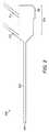
図2では、最小侵襲性手術に使用するためのロボットアーム端部に取り付け可能な内視鏡が示されている。内視鏡200は、患者の手術箇所に挿入する遠位端202および近位端204を有している。遠位端は、長手状シャフト206によって、近位端に連結されている。近位端204は、ロボットアーム端部に係合するためのインターフェース208を有している。 FIG. 2 shows an endoscope that can be attached to the end of a robot arm for use in minimally invasive surgery.
内視鏡は、手術箇所を照らすための動力源および光源を有している。内視鏡は、また、手術箇所から画像データを取得するためのデータラインを有する。これらは皆、図2に示されるように、独立して、ロボットアーム外部で、内視鏡の近位端に取り付けられてもよい。図2において、動力はステム212を通じて加えられ、イメージデータはステム212を通じて取得され、光はライトステム210を通じて加えられる。別の実施形態では、光入力、動力入力、データ出力のうちひとつ以上が、ロボットアームを通じて、内視鏡に対して、加えられ/取得され得る。 The endoscope has a power source and a light source for illuminating a surgical site. The endoscope also has a data line for acquiring image data from a surgical site. These may all be independently attached to the proximal end of the endoscope, outside the robot arm, as shown in FIG. In FIG. 2, power is applied through
内視鏡は、ロボットアーム端部に取り付けられる。ロボットアームは、図1に示される形態をしている。つまり、ロボットアームは、ベースと、内視鏡への取付部であるインターフェースの間を延びている。ロボットアームは、ジョイント近傍に点在する一連の剛性リンクを有している。これらのジョイントにより、ロボットアームを関節連結することができる。 The endoscope is attached to the end of the robot arm. The robot arm has the form shown in FIG. That is, the robot arm extends between the base and an interface that is a mounting portion to the endoscope. The robot arm has a series of rigid links scattered near the joint. With these joints, the robot arm can be articulated.
内視鏡インターフェース204は、ロボットアームの補充インターフェースと係合する。図3Aにはロボットアームに係合中の内視鏡が示され、図3Bには係合された構成の内視鏡およびロボットアームが示される。好適には、内視鏡は、関節連結された遠位端を有さず、したがって、ロボットアームから内視鏡への、ロボットアームインターフェースや内視鏡インターフェースを通じた駆動伝達(例えばケーブル駆動)はない。ロボットアームは、内視鏡を支持する役割のみを持つ。内視鏡はロボットアーム遠位端の硬質な延長部であるから、内視鏡遠位端の向きは、ロボットアーム遠位端の向きと一致する。内視鏡がポートを通じて患者に挿入される距離は、ロボットアームのジョイント構成によって制御される。つまり、内視鏡がポートを通じて患者に挿入される距離は、ロボットアーム遠位端とポート間の距離によって制御される。
内視鏡は、ロボットアームインターフェースおよび内視鏡インターフェースを通じて、ロボットアームに対して着脱可能である。好適には、内視鏡は取り外された状態で、ロボットアームから独立して操作可能である。言い換えれば、内視鏡は、ロボットアームから取り外されているときに、手術室スタッフの一員により手動で操作されることができる。 The endoscope is detachable from the robot arm through the robot arm interface and the endoscope interface. Preferably, the endoscope is operable independently of the robot arm when detached. In other words, the endoscope can be manually operated by a member of the operating room staff when detached from the robot arm.
図3Aおよび図3Bに関して、ロボットアーム遠位端302は、ロボットアームインターフェース304で終端する。ロボットアームの遠位リンク302は、長手方向軸306を有する。内視鏡シャフト206は、長手方向軸308を有する。図3Bからわかるように、内視鏡がロボットアームのドック上にあるときに、内視鏡シャフトの長手方向軸308は、ロボットアームの長手方向軸306と一直線上に揃うように配置される。内視鏡の長手方向軸とロボットアームの長手方向軸を揃えることによって、内視鏡近位端の大きさがロボットアーム遠位端の大きさを超えることによって発生する追加の掃引空間が最小になる。もし、内視鏡が軸を外してロボットアーム遠位端に取り付けられたら、内視鏡近位端の大きさが同じである場合は、内視鏡の掃引空間はより大きくなる。よって、内視鏡の長手方向軸とロボットアーム遠位端の長手方向軸を揃えることによって、外科用ロボットの総体的な作業空間は縮小される。したがって、他の外科用ロボットを、内視鏡を支持する外科用ロボットのより近くに、衝突を避けながら配置することが可能である。 3A and 3B, the robot arm
図4では、ロボットアームの代表的な遠位端が表されている。図4のロボットアームの最終ジョイントはロールジョイント402である。ロールジョイント402によって、ロボットアームの遠位リンク302が、ロールジョイント軸306の周りでロボットアームにおける隣のリンク404に対して相対回転することが可能になる。ロールジョイント軸306は、ロボットアーム遠位端の長手方向軸と一直線上に揃えられる。図4において、ロボットアームの遠位リンク302は、複合ジョイントによって、隣のロボットアームリンク404に連結される。この複合ジョイントはロールジョイント402を含む。複合ジョイントはまた、ピッチジョイント406およびヨージョイント408を含む。ピッチジョイント軸410は、ヨージョイント軸412と交差する。ロールジョイント軸306、ピッチジョイント軸410、ヨージョイント軸412は全て同じ点で交差する。したがって、内視鏡がロボットアームにドッキングされているときは、内視鏡の長手方向軸308は、ロールジョイント軸306と一直線上に揃い、ピッチジョイント軸410およびヨージョイント軸412と交差する。さらに、複合ジョイントは、さらなるロールジョイント313を含み、そのロールジョイント軸416は、ロボットアームの最後から2番目のリンク404の長手方向軸と一直線上に揃えられている。 In FIG. 4, a representative distal end of the robot arm is shown. The final joint of the robot arm of FIG. The roll joint 402 allows the robot arm
図3Aおよび図3Bを参照して、内視鏡インターフェースおよびロボットアームインターフェースは、(各々内視鏡およびロボットアームに)配置される。そして、内視鏡インターフェースおよびロボットアームインターフェースは、内視鏡とロボットアームが内視鏡の長手方向軸308に直交するように、そしてロボットアームの長手方向軸306とも直交するように組み合わせられて相互に係合する形状にされている。図3Aおよび図3Bの例において、ロボットアームインターフェース304は、おおむねロボットアーム遠位リンク長手方向軸306に平行な方向および、同軸306を横切る方向に伸びている。同様に、内視鏡インターフェース204は、おおむね、外科用内視鏡長手方向軸308に平行な方向および同軸308を横切る方向に伸びている。両インターフェースは略平面である。 Referring to FIGS. 3A and 3B, the endoscope interface and the robot arm interface are located (on the endoscope and the robot arm, respectively). The endoscope interface and the robot arm interface are then interconnected such that the endoscope and the robot arm are orthogonal to the
ロボットアームインターフェース304はまた、ロボットアームの長手方向軸306を横切るリム310を有する。ロボットアーム遠位リンクの長手方向軸306の方向において内視鏡インターフェースを収容して保持することのできるロボットアームインターフェース304の長さが、リムによって制限される。この長さは、内視鏡の長手方向軸308の方向における内視鏡インターフェースの長さとなるよう制限される。したがって、ロボットアーム遠位リンクの長手方向軸に直交する方向において、内視鏡インターフェースがロボットアームインターフェースに係合しているときに、ロボットアームインターフェースが内視鏡インターフェースを収容して係合することだけができるように、ロボットアームインターフェースがリムの働きによって抑制される。つまり、ロボットアーム遠位端長手方向軸306の方向における運動成分をもって、内視鏡インターフェースが、ロボットアームインターフェースと係合することはできない。 The
内視鏡を取り外すときに内視鏡長手方向軸308の方向において内視鏡が動かないようにすれば、取り外し動作の安全性が高まる。これは、仮に内視鏡が患者内で静止しているときにロボットアームから取り外された場合に、内視鏡を更に押し込むと甚大な損傷を引き起こすおそれがある手術箇所において、取り外し動作がそのような損傷の原因にはならないからである。 If the endoscope is prevented from moving in the direction of the endoscope
好適には、内視鏡は、人間の片手によってロボットアームに対して着脱可能である。内視鏡とロボットアームを係合して係止する機構が使用される。この機構は人手によって操作可能である。この機構は全体が内視鏡インターフェースとロボットアームインターフェースの一方の内部に収容される。内視鏡インターフェースおよびロボットアームインターフェースの動く部位をすべて、内視鏡インターフェースおよびロボットアームインターフェースの一方の内部に配置することによって、内視鏡は、ロボットアームに対して片手で着脱可能になる。 Preferably, the endoscope is detachable from the robot arm by one hand of a human. A mechanism for engaging and locking the endoscope and the robot arm is used. This mechanism is manually operable. This mechanism is entirely housed inside one of the endoscope interface and the robot arm interface. By arranging all the moving parts of the endoscope interface and the robot arm interface inside one of the endoscope interface and the robot arm interface, the endoscope can be attached to and detached from the robot arm with one hand.
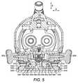
図5,6,7は、係合の様々な段階における、代表的な内視鏡とロボットアームの断面図である。この断面は、ロボットアーム長手方向軸306および内視鏡長手方向軸308に直交する平面に存在する。図5において、内視鏡とロボットアームは係合係止されている。図6および7において、内視鏡とロボットアームは部分的に係合されている。図5〜7に示される例において、内視鏡とロボットアームを係合係止するために使用されている機構は、全体が内視鏡インターフェース内部に収容されている。ロボットアームインターフェースは、静的成分のみを含む。別の例において、内視鏡とロボットアームを係合係止するために使用されている機構は、全体がロボットアームインターフェース内部に収容されてもよい。この場合、内視鏡インターフェースは静的成分のみを含んでもよい。 FIGS. 5, 6, and 7 are cross-sectional views of a representative endoscope and robot arm at various stages of engagement. This cross section lies in a plane orthogonal to the robot arm
図5を参照して、内視鏡インターフェースは、内視鏡ウェッジ機構を有する。内視鏡ウェッジ機構は、使用者によって作動されて、内視鏡のロボットアームに対する係合または係合解除を行う。この機構は、非固定状態と固定状態のいずれかへ移動可能である。内視鏡ウェッジ機構は、移動可能な内視鏡ウェッジエレメント502,504を含む。ウェッジエレメントは、内視鏡外形から突出する。内視鏡とロボットアームが係合されているときに、ロボットアームインターフェースにおいて保持されるのはウェッジエレメントである。使用者がウェッジ機構を作動すると、ウェッジエレメントが変位する。内視鏡ウェッジエレメントが集団的に変位すると、内視鏡ウェッジ機構が非固定状態と固定状態のいずれかへ作動される。 Referring to FIG. 5, the endoscope interface has an endoscope wedge mechanism. The endoscope wedge mechanism is actuated by a user to engage or disengage the endoscope with the robot arm. The mechanism is movable between an unfixed state and a fixed state. The endoscope wedge mechanism includes movable endoscope wedge elements 502,504. The wedge element protrudes from the endoscope outer shape. It is the wedge element that is held at the robot arm interface when the endoscope and the robot arm are engaged. When the user operates the wedge mechanism, the wedge element is displaced. When the endoscope wedge elements are collectively displaced, the endoscope wedge mechanism is activated to either a non-fixed state or a fixed state.
図5では、2つの内視鏡ウェッジエレメント502,504が表されている。内視鏡長手方向軸308に対して直交する方向Aにおいて、これらの内視鏡ウェッジエレメントは離隔している。図5の固定状態を図7の非固定状態と比較することによって、非固定状態よりも固定状態の方が、方向Aにおいて、大きな距離で内視鏡ウェッジエレメントが離隔していることを見て取ることができる。内視鏡ウェッジエレメント502,504は、方向Aにおいて、変位可能である。内視鏡ウェッジエレメント502,504が互いに向かって変位すると、内視鏡ウェッジ機構は非固定状態になるように移動する。内視鏡ウェッジエレメント502,504が相互に離れるように変位すると、内視鏡ウェッジ機構は固定状態になるように移動する。 In FIG. 5, two
内視鏡近位端の外側で、使用者操作部506,508において終端するアーム510,512に、各内視鏡ウェッジエレメントは連結される。これらアームは、図5〜7に示されるように並べられてもよい。使用者操作部は、内視鏡ウェッジ機構が固定状態にあるときに、内視鏡外形の外側に露出されてもよい。使用者操作部は、図5〜7に示される内視鏡外側の対向側面上で露出してもよい。使用者操作部は、使用者によって押し下げることができる。各アームは方向Aにおいて変位可能である。使用者が方向Aにおいて使用者操作部506,508を押し下げると、アームひいては内視鏡ウェッジエレメントが方向Aにおいて変位する。内視鏡ウェッジエレメント502,504の2つの使用者操作部506,508ひいては2つのアーム510,512が互いに向かって変位すると、内視鏡ウェッジ機構は非固定状態になるように移動する。内視鏡ウェッジエレメント502,504の2つの使用者操作部506,508ひいては2つのアーム510,512が互いに離隔するように変位すると、内視鏡ウェッジ機構は固定状態になるように移動する。 Outside the proximal end of the endoscope, each endoscope wedge element is connected to
内視鏡ウェッジ機構の固定状態における各配置に向けて、内視鏡ウェッジエレメントは偏向させられてもよい。図5〜7の例において、内視鏡ウェッジエレメント502,504は、内視鏡ウェッジ機構の固定状態における各配置に向かって、ばねで偏向させられている。ばね514は、アーム510ひいては一方の内視鏡ウェッジエレメント502の、方向Aにおける他方の内視鏡ウェッジエレメント504への変位に抵抗する。ばね514は、使用者によって使用者操作部506に対して加えられる力に対向するばね力を持つ。図5〜7の例において、ばね514はアーム510内部にあり、方向Aにおいて圧縮したり拡張したりするように巻かれている。使用者が使用者操作部506に、ばね514の対向力を超える使用者の力を加えると、内視鏡ウェッジ機構は非固定状態へと移動する。使用者が使用者操作部506を放すと、ばね力が使用者の力よりも大きくなり、内視鏡ウェッジ機構は、固定状態へと戻る。ばね516は、アーム512ひいては一方の内視鏡ウェッジエレメント504の、方向Aにおける他方の内視鏡ウェッジエレメント504への変位に抵抗する。ばね516は、使用者によって使用者操作部508に対して加えられる力に対向するばね力を持つ。図5〜7の例において、ばね516はアーム512内部にあり、方向Aにおいて圧縮したり拡張したりするように巻かれている。ばね516は、ばね514と同じばねであってもよい。使用者が使用者操作部508に、ばね516の対向力を超える使用者の力を加えると、内視鏡ウェッジ機構は非固定状態になるように移動する。使用者が使用者操作部508を放すと、ばね力が使用者の力よりも大きくなり、内視鏡ウェッジ機構は、固定状態へと戻る。よって、使用者操作部506,508に対してばね514,516の力を超える使用者の対向力を加えることによって、使用者は内視鏡ウェッジ機構を図5の固定状態から離れて図7の非固定状態になるように移動させる。 The endoscope wedge element may be deflected towards each fixed position of the endoscope wedge mechanism. In the examples of FIGS. 5 to 7, the
内視鏡ウェッジ機構は、その固定状態において内視鏡ウェッジエレメントを各配置に抑制するロックをさらに含んでもよい。このロックは、内視鏡ウェッジ機構の非固定状態において内視鏡ウェッジエレメントを抑制しない。図5〜7の例において、ロックは、方向Aを横切る方向Bにおいて移動可能なプランジャー518を含む。図5に示される固定状態で、プランジャー518は、内視鏡ウェッジエレメント502,504を分け広げる。図6と7に示される非固定状態で、プランジャーは方向Aにおいて内視鏡ウェッジエレメント502,504の位置を妨害しない。プランジャーは、固定状態における配置に向かって偏向される。図5の例において、プランジャーはばね520によって、固定状態へとばね偏向される。ばね520は、内視鏡ウェッジエレメント間にプランジャーを押し込む方向Bのばね力を持つ。ばね520は、方向Bにおいて、圧縮したり拡張したりするように、プランジャー518の長手方向軸の周りで巻かれる。 The endoscope wedge mechanism may further include a lock that restrains the endoscope wedge element in each position in its fixed state. This lock does not restrain the endoscope wedge element when the endoscope wedge mechanism is in the unlocked state. In the example of FIGS. 5-7, the lock includes a
図5の内視鏡ウェッジエレメント502は、互いに向かって移動可能である2つの部分である、嵌合ウェッジ526および突出部524を有する。嵌合ウェッジ526は、ロボットアームインターフェースの補足的なロボットアームウェッジエレメントと嵌合する。プランジャー518は、突出部524と係合する面形状部を有する。図5で、この面形状部は、傾斜案内部522である。突出部524は、傾斜案内部522への補足的形状をしている。 The
突出部524は、内視鏡ウェッジ機構の固定状態における配置に向かって偏向している。図5〜7の例で、突出部524は、内視鏡ウェッジ機構の固定状態における配置に向かってばねで偏向している。ばね530は、方向Aにおけるプランジャー518へのアーム510ひいては突出部524の変位に抵抗する。ばね530は、使用者から、使用者操作部506に加えられた力に対向するばね力を持つ。ばね530はアーム510内部にあり、方向Aにおいて圧縮したり拡張したりするように巻かれている。使用者が使用者操作部506に、ばね530の対向力を超える使用者の力を加えると、突出部524は方向Aにおいてプランジャー518に向かって移動する。突出部524と案内部522の傾斜した形状のおかげで、突出部がプランジャー518に接触した後、突出部524がプランジャーに向かってさらに移動すると、プランジャーは嵌合ウェッジ526,528の間から離れて方向Bにおいて移動する。プランジャー518への突出部524の力は、ばね520のばね偏向を克服し、結果として、プランジャー518は、嵌合ウェッジ526,528の間から離れて方向Bにおいて変位する。図6は、プランジャー518に向かって最大に移動した突出部524を表す。プランジャー518は、嵌合ウェッジ526,528の移動を阻害していない。使用者が使用者操作部506を放すと、ばね530の力が使用者の力よりも大きくなり、突出部518がプランジャー518から離れて方向Aにおいて移動する。結果として、プランジャーは嵌合ウェッジ526,528の間で移動する。 The
1つの突出部524と1つのプランジャー518だけが図5〜7で表されているが、2つ以上の突出部が1つ以上のプランジャーに係合してもよい。これらの突出部は、片方あるいは両方のアームに連結されてもよい。 Although only one
図5〜7の例において、突出部524および嵌合ウェッジ526は、それぞればね530および514から、両方、同じ方向の偏向力を受ける。同じ使用者操作部506に力を加えることによって、突出部524および嵌合ウェッジ526両方の変位が作動される。例えば、嵌合ウェッジより軽く突出部にばねをつけることによって、突出部の偏向力は、選ばれて嵌合ウェッジの偏向力よりも低くなる。したがって、使用者が使用者操作部に力を加えると、突出部の偏向力は、嵌合ウェッジの偏向力の前に克服される。よって、内視鏡ウェッジ機構の固定状態において、使用者が使用者操作部に対して力を加えると、嵌合ウェッジ526が方向Aにおいて他方の嵌合ウェッジ528に向かって移動する前に、突出部524が方向Aにおいてプランジャー518に向かって移動する。したがって、使用者が使用者操作部に力を加えると、内視鏡ウェッジ機構は、プランジャー518が嵌合ウェッジ526,528を分け広げる図5の固定時構成から、プランジャー518が嵌合ウェッジ526,528の間から抜け出た図6の非固定時構成になるよう移動する。使用者が使用者操作部にさらに力を加えると、内視鏡ウェッジ機構は、図6の非固定時構成から、内視鏡インターフェースがロボットアームインターフェースから取り外し可能な、図7の係合解除可能構成になるよう移動する。 In the example of FIGS. 5-7,
2つの内視鏡ウェッジエレメント502,504について記述してきたが、さらなる内視鏡ウェッジエレメントを利用してもよい。これらのさらなる内視鏡ウェッジエレメントは、図5〜7に示される同じ使用者操作部またはさらなる使用者操作部によって作動されてもよい。 Although two
図5〜7のロボットアームインターフェースについて説明する。ロボットアームインターフェースは、内視鏡インターフェースエレメントに係合するためのロボットアームインターフェースエレメントを含む。詳細には、ロボットアームインターフェースは、内視鏡ウェッジエレメント502,504を保持するためのロボットアームウェッジエレメント532,534を含む。内視鏡ウェッジエレメント502,504とロボットアームウェッジエレメント532,534の両方が、内視鏡インターフェースがロボットアームインターフェースと係合する方向に対して傾斜している面を有する。内視鏡ウェッジエレメント502の傾斜面は、ロボットアームウェッジエレメント532の傾斜面に接触する。内視鏡ウェッジエレメント504の傾斜面は、ロボットアームウェッジエレメント534の傾斜面に接触する。これらの接触面は、内視鏡インターフェースおよびロボットアームインターフェースが係合しているときに、内視鏡インターフェースとロボットアームインターフェースの係合方向においてロボットアームウェッジエレメント532,534が内視鏡ウェッジエレメントを抑制するように角度付けられている。言い換えれば、図5に示されている固定状態において、ロボットアームウェッジエレメント532,534の傾斜面によって、内視鏡インターフェースが方向Bにおいてロボットアームインターフェースから離れて上昇するのが防止される。内視鏡インターフェースが、他の方向へ、ロボットアームインターフェースから離れて上昇することもまた防止される。よって、内視鏡端部にかかる横方向の力は、内視鏡インターフェースが、ロボットアームインターフェースから外れる原因にはならない。各ロボットアームウェッジエレメントは、それが保持する内視鏡ウェッジエレメントへの補足的な形状をしている。 The robot arm interface shown in FIGS. The robot arm interface includes a robot arm interface element for engaging the endoscope interface element. In particular, the robot arm interface includes robot
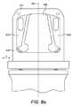
ロボットアームウェッジエレメント532,534の離隔距離は、ロボットアームインターフェースの長さにわたって変化してもよい。図8Aおよび8Bは、図5〜7の断面を横切り、内視鏡シャフトの長手方向軸308およびロボットアーム遠位リンクの長手方向軸306に平行である、内視鏡インターフェースとロボットアームインターフェースの断面を示す。図8Aはロボットアームインターフェースを表し、図8Bは内視鏡インターフェースを表す。ロボットアームウェッジエレメント532,534の離隔距離が、ロボットアームの末端リンクの長手方向軸306の方向において変化することを見て取ることが可能である。ロボットアームウェッジエレメント532,534の離隔が縮まると、それらはロボットアーム遠位リンクからさらに遠くなる。方向Aにおける内視鏡ウェッジエレメント502,504の幅は、ロボットアームインターフェースの長さにわたるロボットアームウェッジエレメントの離隔に対応して、内視鏡インターフェースの長さにわたって変化することが見て取れる。よって、内視鏡インターフェースは、1つの位置のみにおいて、ロボットアームインターフェースに係合する。 The separation of the robot
滅菌環境を確保するために、手術室で使用される部品は予め滅菌されるか、滅菌ドレープで覆われる。好適には、ロボットアームと内視鏡の両方が、患者の滅菌バリアを維持するためにドレープを掛けられる。ロボットアームおよび内視鏡は、独立してドレープを掛けられていてもよい。ロボットアームと内視鏡に、別々にドレープを掛けることで、患者に対して滅菌バリアを依然維持したままで、内視鏡をロボットアームから取り外して、ロボットアームから独立して使用することができる。図3Aおよび図3Bには、内視鏡(または内視鏡の滅菌されていない部分)を覆う内視鏡ドレープ312およびロボットアームを覆うロボットアームドレープ314が表されている。 To ensure a sterile environment, components used in the operating room are pre-sterilized or covered with sterile drapes. Preferably, both the robot arm and the endoscope are draped to maintain a sterile barrier for the patient. The robot arm and endoscope may be independently draped. Separate drapes on the robot arm and endoscope allow the endoscope to be removed from the robot arm and used independently of the robot arm, while still maintaining a sterile barrier for the patient . 3A and 3B show an
滅菌バリアは、ロボットアームインターフェースおよび内視鏡インターフェースを越えて広がる。ある実施形態において、ロボットアームインターフェースの1つ以上の構成要素がロボットアームドレープに対して一体的であってもよい。例えば、ロボットアームインターフェースの1つ以上の構成要素がロボットアームドレープに固着されていてもよい。同様に、内視鏡インターフェースの1つ以上の構成要素が内視鏡ドレープに対して一体的であってもよい。例えば、内視鏡インターフェースの1つ以上の構成要素が内視鏡ドレープに固着されていてもよい。したがって、ロボットアームインターフェースは、ロボットアームの一部である構成要素およびロボットアームドレープの一部である構成要素を含んでいる。同様に、内視鏡インターフェースは、内視鏡の一部である構成要素と内視鏡ドレープの一部である構成要素を含んでいる。内視鏡インターフェースがロボットアームインターフェースに係合するとき、内視鏡ドレープとロボットアームドレープの間に接触がある。 The sterilization barrier extends beyond the robot arm interface and the endoscope interface. In some embodiments, one or more components of the robot arm interface may be integral to the robot arm drape. For example, one or more components of the robot arm interface may be secured to the robot arm drape. Similarly, one or more components of the endoscope interface may be integral to the endoscope drape. For example, one or more components of the endoscope interface may be secured to the endoscope drape. Thus, the robot arm interface includes components that are part of the robot arm and components that are part of the robot arm drape. Similarly, the endoscope interface includes components that are part of the endoscope and components that are part of the endoscope drape. When the endoscope interface engages the robot arm interface, there is contact between the endoscope drape and the robot arm drape.
この配置において、図5を参照して、ロボットアームドレープは、ロボットアームウェッジエレメント532,534を含んでいる。ロボットアームドレープはまた、補強エレメント536を含む。ロボットアームは、ロボットアームインターフェースの本体538を含む。本体538は、ロボットアームドレープエレメント532,534,536を保持する。これらのロボットアームドレープエレメントは、本体から取り外し可能である。本体538は、ロボットアームウェッジエレメント532,534と補強エレメント536のそれぞれを保持するリップ540を含んで構成されている。本体538は、リム310もまた、有している。 In this arrangement, referring to FIG. 5, the robot arm drape includes robot
内視鏡嵌合ウェッジ526,528は、それぞれ、内視鏡ドレープの部分である内視鏡ドレープウェッジエレメント542,544と、内視鏡の部分である内視鏡組立部品ウェッジエレメント546,548を有する。内視鏡ドレープウェッジエレメントは、内視鏡組立部品ウェッジエレメントから取り外し可能である。内視鏡ドレープウェッジエレメント542,544は、内視鏡組立部品ウェッジエレメント546,548によって保持される。内視鏡ドレープウェッジエレメント542,544の接触面は、内視鏡組立部品ウェッジエレメント546,548に対して補足的な形状にされている。内視鏡組立部品ウェッジエレメント546,548は、内視鏡ドレープウェッジエレメント542,544の補足的形状の面形状部を保持する先端550のような面形状部を含んでいる。これらの面形状部は、内視鏡ドレープウェッジエレメントを内視鏡組立部品ウェッジエレメントに固定し、内視鏡を内視鏡ドレープから取り外す力に抵抗する。 The
他の実施形態において、ロボットアームインターフェースに掛かるロボットアームドレープの部分は、ロボットアームインターフェースのいずれの構成要素も含んでいなくてもよい。例えば、ロボットアームドレープのこの部分は、布地のみで構成されて、硬質な構成要素がなくてもよい。この布地は、ロボットアームドレープの残りと同じ布地であってもよい。あるいは、ロボットアームインターフェースに掛かる布地は、ロボットアームドレープの残りの布地に比して補強されてもよい。内視鏡インターフェースに掛かる内視鏡ドレープの部分は、内視鏡インターフェースのいずれの構成要素も含んでいなくてもよい。例えば、内視鏡ドレープのこの部分は、布地のみで構成されて、硬質な構成要素がなくてもよい。この布地は、内視鏡ドレープの残りと同じ布地であってもよい。あるいは、内視鏡インターフェースに掛かる布地は、内視鏡ドレープの残りの布地に比して補強されてもよい。これらの実施形態において、ロボットアームウェッジエレメント532,534および補強エレメント536のうちひとつ以上が、ロボットアームインターフェースの本体538と一体であってもよい。これらの構成要素は、ロボットアームインターフェースから取り外せず、したがって、使用中のロボットアームからも取り外せない。同様に、各内視鏡嵌合ウェッジは、一体的に形成されてもよい。つまり、内視鏡嵌合ウェッジ526は、取り外し可能な構成要素542および546を含まない。そして、内視鏡嵌合ウェッジ528は、取り外し可能な構成要素544および548を含まない。これらの構成要素は、内視鏡インターフェースから取り外せず、よって、使用中の内視鏡から取り外せない。 In other embodiments, the portion of the robot arm drape that hangs on the robot arm interface may not include any components of the robot arm interface. For example, this part of the robot arm drape may consist of only fabric and no rigid components. This fabric may be the same fabric as the rest of the robot arm drape. Alternatively, the fabric hanging on the robot arm interface may be reinforced relative to the remaining fabric of the robot arm drape. The portion of the endoscope drape that spans the endoscope interface may not include any components of the endoscope interface. For example, this portion of the endoscope drape may be comprised of only fabric and no rigid components. This fabric may be the same fabric as the rest of the endoscope drape. Alternatively, the fabric hanging over the endoscope interface may be reinforced relative to the remaining fabric of the endoscope drape. In these embodiments, one or more of the robot
模造内視鏡インターフェースが、外科用ロボットの環境の特性把握過程で利用されてもよい。模造内視鏡インターフェースは、本明細書に記述されている内視鏡ウェッジ機構を有する。好適には、模造内視鏡インターフェースは、内視鏡の他のどのような特徴も有しない。模造内視鏡インターフェースは、例えば患者のテーブル上の既知の場所などの、手術室内の既知の場所に配置されてもよい。手術前の内視鏡ロボットアームの立ち上げ時に、ロボットアームインターフェースは、模造内視鏡インターフェースの所に運ばれ、これら2つは、本明細書に記載の手順で係合される。ロボットアームの制御システムは、(ロボットアームに付されている位置センサから受信したジョイント構成信号からの)ロボットアームのジョイントの既知の構成を使用する。そして、手術室内でロボットアーム位置を決定するために模造内視鏡インターフェースと係合しているときに、模造内視鏡インターフェースの既知の位置と方向、ロボットアームインターフェースの既知の位置と方向を使用する。制御システムはまた、ロボットアームに付されているトルクセンサから取得したトルク測定値を使用して、ロボットアームに働く重力の方向を決定し、それによりロボットアームの方向も決定してもよい。 An imitation endoscope interface may be utilized in the process of characterizing the environment of the surgical robot. The simulated endoscope interface has the endoscope wedge mechanism described herein. Preferably, the imitation endoscope interface does not have any other features of the endoscope. The imitation endoscope interface may be located at a known location in the operating room, for example, at a known location on a patient's table. Upon startup of the endoscopic robotic arm prior to surgery, the robotic arm interface is brought to the simulated endoscope interface, and the two are engaged in the manner described herein. The control system of the robot arm uses a known configuration of the joints of the robot arm (from a joint configuration signal received from a position sensor attached to the robot arm). And use the known position and orientation of the imitation endoscope interface and the known position and orientation of the robot arm interface when engaged with the imitation endoscope interface to determine the robot arm position in the operating room. I do. The control system may also use the torque measurements obtained from the torque sensors attached to the robot arm to determine the direction of gravity acting on the robot arm, and thereby determine the direction of the robot arm.
内視鏡およびロボットアームは、非外科的用途で使用されてもよい。例えば、内視鏡は、産業ロボット製造・加工手順において使用されてもよい。 Endoscopes and robotic arms may be used in non-surgical applications. For example, endoscopes may be used in industrial robot manufacturing and processing procedures.
出願人はこれによって、ここに記載の各個別の特徴および2つ以上のそのような特徴の任意の組み合わせを別々に開示しており、そのような特徴または特徴の組み合わせが当業者の共通の一般的な知識に照らして全体として本明細書に基づいて実施されることが可能な程度に開示している。なお、そのような特徴または特徴の組み合わせが本明細書に開示される問題を解決するかどうかは関係がなく、またかかる具体的記載が特許請求の範囲を限定するものでもない。出願人は、本発明の態様は、このような個々の特徴または特徴の組み合わせから成ってもよいことを示している。以上の説明に鑑みて、種々の改変が本発明の範囲内でなされ得ることは当業者にとって明らかであろう。 Applicants hereby separately disclose each individual feature described herein and any combination of two or more such features, and such features or combinations of features may be shared by one of ordinary skill in the art. It is disclosed to the extent that it can be implemented on the basis of the present specification in the light of technical knowledge as a whole. It does not matter whether such features or combinations of features solve the problems disclosed herein, and such specific description does not limit the scope of the claims. Applicants have shown that aspects of the present invention may consist of such individual features or combinations of features. In view of the above description, it will be apparent to one skilled in the art that various modifications may be made within the scope of the present invention.
図4では、ロボットアームの代表的な遠位端が表されている。図4のロボットアームの最終ジョイントはロールジョイント402である。ロールジョイント402によって、ロボットアームの遠位リンク302が、ロールジョイント軸306の周りでロボットアームにおける隣のリンク404に対して相対回転することが可能になる。ロールジョイント軸306は、ロボットアーム遠位端の長手方向軸と一直線上に揃えられる。図4において、ロボットアームの遠位リンク302は、複合ジョイントによって、隣のロボットアームリンク404に連結される。この複合ジョイントはロールジョイント402を含む。複合ジョイントはまた、ピッチジョイント406およびヨージョイント408を含む。ピッチジョイント軸410は、ヨージョイント軸412と交差する。ロールジョイント軸306、ピッチジョイント軸410、ヨージョイント軸412は全て同じ点で交差する。したがって、内視鏡がロボットアームにドッキングされているときは、内視鏡の長手方向軸308は、ロールジョイント軸306と一直線上に揃い、ピッチジョイント軸410およびヨージョイント軸412と交差する。さらに、複合ジョイントは、さらなるロールジョイント414を含み、そのロールジョイント軸416は、ロボットアームの最後から2番目のリンク404の長手方向軸と一直線上に揃えられている。In FIG. 4, a representative distal end of the robot arm is shown. The final joint of the robot arm of FIG. The roll joint 402 allows the robot arm
内視鏡ウェッジ機構の固定状態における各配置に向けて、内視鏡ウェッジエレメントは偏向させられてもよい。図5〜7の例において、内視鏡ウェッジエレメント502,504は、内視鏡ウェッジ機構の固定状態における各配置に向かって、ばねで偏向させられている。ばね514は、アーム510ひいては一方の内視鏡ウェッジエレメント502の、方向Aにおける他方の内視鏡ウェッジエレメント504への変位に抵抗する。ばね514は、使用者によって使用者操作部506に対して加えられる力に対向するばね力を持つ。図5〜7の例において、ばね514はアーム510内部にあり、方向Aにおいて圧縮したり拡張したりするように巻かれている。使用者が使用者操作部506に、ばね514の対向力を超える使用者の力を加えると、内視鏡ウェッジ機構は非固定状態へと移動する。使用者が使用者操作部506を放すと、ばね力が使用者の力よりも大きくなり、内視鏡ウェッジ機構は、固定状態へと戻る。ばね516は、アーム512ひいては一方の内視鏡ウェッジエレメント504の、方向Aにおける他方の内視鏡ウェッジエレメント502への変位に抵抗する。ばね516は、使用者によって使用者操作部508に対して加えられる力に対向するばね力を持つ。図5〜7の例において、ばね516はアーム512内部にあり、方向Aにおいて圧縮したり拡張したりするように巻かれている。ばね516は、ばね514と同じばねであってもよい。使用者が使用者操作部508に、ばね516の対向力を超える使用者の力を加えると、内視鏡ウェッジ機構は非固定状態になるように移動する。使用者が使用者操作部508を放すと、ばね力が使用者の力よりも大きくなり、内視鏡ウェッジ機構は、固定状態へと戻る。よって、使用者操作部506,508に対してばね514,516の力を超える使用者の対向力を加えることによって、使用者は内視鏡ウェッジ機構を図5の固定状態から離れて図7の非固定状態になるように移動させる。The endoscope wedge element may be deflected towards each fixed position of the endoscope wedge mechanism. In the examples of FIGS. 5 to 7, the
突出部524は、内視鏡ウェッジ機構の固定状態における配置に向かって偏向している。図5〜7の例で、突出部524は、内視鏡ウェッジ機構の固定状態における配置に向かってばねで偏向している。ばね530は、方向Aにおけるプランジャー518へのアーム510ひいては突出部524の変位に抵抗する。ばね530は、使用者から、使用者操作部506に加えられた力に対向するばね力を持つ。ばね530はアーム510内部にあり、方向Aにおいて圧縮したり拡張したりするように巻かれている。使用者が使用者操作部506に、ばね530の対向力を超える使用者の力を加えると、突出部524は方向Aにおいてプランジャー518に向かって移動する。突出部524と案内部522の傾斜した形状のおかげで、突出部がプランジャー518に接触した後、突出部524がプランジャーに向かってさらに移動すると、プランジャーは嵌合ウェッジ526,528の間から離れて方向Bにおいて移動する。プランジャー518への突出部524の力は、ばね520のばね偏向を克服し、結果として、プランジャー518は、嵌合ウェッジ526,528の間から離れて方向Bにおいて変位する。図6は、プランジャー518に向かって最大に移動した突出部524を表す。プランジャー518は、嵌合ウェッジ526,528の移動を阻害していない。使用者が使用者操作部506を放すと、ばね530の力が使用者の力よりも大きくなり、突出部524がプランジャー518から離れて方向Aにおいて移動する。結果として、プランジャーは嵌合ウェッジ526,528の間で移動する。The
Claims (36)
Translated fromJapanese患者に挿入するための遠位端および近位端を有するシャフトと、
前記シャフトの前記近位端に取り付けられる内視鏡インターフェースであって、前記外科用ロボットアームのロボットアームインターフェースと係合するように構成されている前記内視鏡インターフェースと、
を含み、
前記内視鏡インターフェースが、非固定状態と固定状態のいずれかへ変位可能な内視鏡ウェッジ機構を含み、
前記内視鏡ウェッジ機構が、複数の内視鏡ウェッジエレメントを含み、前記複数の内視鏡ウェッジエレメントは集合的に変位することで、前記内視鏡ウェッジ機構を前記非固定状態と前記固定状態のいずれかに作動させるよう変位可能であり、前記固定状態では、前記複数の内視鏡ウェッジエレメントが前記ロボットアームインターフェースに保持されている
外科用内視鏡。A surgical endoscope for operation by a surgical robotic arm, comprising:
A shaft having a distal end and a proximal end for insertion into a patient;
An endoscope interface attached to the proximal end of the shaft, wherein the endoscope interface is configured to engage a robot arm interface of the surgical robot arm;
Including
The endoscope interface includes an endoscope wedge mechanism that can be displaced to any of a non-fixed state and a fixed state,
The endoscope wedge mechanism includes a plurality of endoscope wedge elements, and the plurality of endoscope wedge elements are collectively displaced to bring the endoscope wedge mechanism into the non-fixed state and the fixed state. Wherein the plurality of endoscope wedge elements are held in the robot arm interface in the fixed state.
一連の中間関節連結ロボットアームリンクを通じて遠位ロボットアームリンクに連結されるロボットベースと、
前記遠位ロボットアームリンクに取り付けられ、前記外科用内視鏡の内視鏡インターフェースを収容して係合する前記ロボットアームインターフェースとを含み、
前記ロボットアームインターフェースが、前記内視鏡インターフェースの複数の内視鏡インターフェースエレメントと係合するための複数のロボットアームインターフェースエレメントを含み、すべての前記ロボットアームインターフェースエレメントが前記ロボットアームインターフェース内で固定されており、
前記ロボットアームインターフェースが、前記遠位ロボットアームリンクの長手方向軸に垂直な方向において前記内視鏡インターフェースと前記ロボットアームインターフェースが係合するときに、前記内視鏡インターフェースの収容と係合のみをするように形成されている
外科用ロボット。A surgical robot for operating a surgical endoscope, wherein the surgical robot is
A robot base connected to the distal robot arm link through a series of intermediate articulated robot arm links;
Said robot arm interface attached to said distal robot arm link for receiving and engaging an endoscope interface of said surgical endoscope;
The robot arm interface includes a plurality of robot arm interface elements for engaging with a plurality of endoscope interface elements of the endoscope interface, all the robot arm interface elements being secured within the robot arm interface. And
The robot arm interface only engages and engages the endoscope interface when the endoscope interface and the robot arm interface engage in a direction perpendicular to the longitudinal axis of the distal robot arm link. A surgical robot that is configured to do so.
一連の中間関節連結ロボットアームリンクを通じて遠位ロボットアームリンクに連結されるロボットベースと、
前記遠位ロボットアームリンクに取り付けられるロボットアームインターフェースと、
外科用内視鏡で、
患者に挿入するための遠位端および近位端を有するシャフトと、
前記シャフトの前記近位端に取り付けられる内視鏡インターフェースと、
を有する前記外科用内視鏡と、
を含んで構成されている外科用ロボットで、
前記遠位ロボットアームリンクの長手方向軸が前記外科用内視鏡の長手方向軸と一直線に揃う状態で前記ロボットアームインターフェースが前記内視鏡インターフェースを収容して係合するようになっている
外科用ロボット。A surgical robot for operating a surgical endoscope,
A robot base connected to the distal robot arm link through a series of intermediate articulated robot arm links;
A robot arm interface attached to the distal robot arm link;
With a surgical endoscope,
A shaft having a distal end and a proximal end for insertion into a patient;
An endoscope interface attached to the proximal end of the shaft;
The surgical endoscope having:
A surgical robot comprising
A surgical device wherein the robot arm interface receives and engages the endoscope interface with a longitudinal axis of the distal robot arm link aligned with a longitudinal axis of the surgical endoscope. For robots.
前記模造内視鏡インターフェースは非固定状態と固定状態のいずれかへ移動可能な内視鏡ウェッジ機構を含み、
前記内視鏡ウェッジ機構が複数の内視鏡ウェッジエレメントを含み、前記複数の内視鏡ウェッジエレメントは集合的に変位することで、前記内視鏡ウェッジ機構を前記非固定状態と前記固定状態のいずれかに作動させるよう変位可能であり、前記固定状態では、前記複数の内視鏡ウェッジエレメントが前記ロボットアームインターフェースに保持されている模造内視鏡インターフェース。A dummy endoscope interface that fits with a robot arm interface of the surgical robot in a process of understanding the characteristics of the environment of the surgical robot,
The imitation endoscope interface includes an endoscope wedge mechanism movable to any of a non-fixed state and a fixed state,
The endoscope wedge mechanism includes a plurality of endoscope wedge elements, and the plurality of endoscope wedge elements are collectively displaced, thereby changing the endoscope wedge mechanism between the non-fixed state and the fixed state. A dummy endoscope interface displaceable to actuate any of the plurality of endoscope wedge elements in the fixed state, wherein the plurality of endoscope wedge elements are held by the robot arm interface.
Priority Applications (2)
| Application Number | Priority Date | Filing Date | Title |
|---|---|---|---|
| JP2022200376AJP7448623B2 (en) | 2017-02-07 | 2022-12-15 | surgical robot |
| JP2024030172AJP2024073486A (en) | 2017-02-07 | 2024-02-29 | Surgical Robots |
Applications Claiming Priority (3)
| Application Number | Priority Date | Filing Date | Title |
|---|---|---|---|
| GB1702006.6 | 2017-02-07 | ||
| GB1702006.6AGB2559420B (en) | 2017-02-07 | 2017-02-07 | Mounting an endoscope to a surgical robot |
| PCT/GB2018/050336WO2018146463A2 (en) | 2017-02-07 | 2018-02-06 | Mounting an endoscope to a surgical robot |
Related Child Applications (1)
| Application Number | Title | Priority Date | Filing Date |
|---|---|---|---|
| JP2022200376ADivisionJP7448623B2 (en) | 2017-02-07 | 2022-12-15 | surgical robot |
Publications (3)
| Publication Number | Publication Date |
|---|---|
| JP2020508725Atrue JP2020508725A (en) | 2020-03-26 |
| JP2020508725A5 JP2020508725A5 (en) | 2021-03-11 |
| JP7320906B2 JP7320906B2 (en) | 2023-08-04 |
Family
ID=58462305
Family Applications (3)
| Application Number | Title | Priority Date | Filing Date |
|---|---|---|---|
| JP2019542534AActiveJP7320906B2 (en) | 2017-02-07 | 2018-02-06 | surgical endoscope |
| JP2022200376AActiveJP7448623B2 (en) | 2017-02-07 | 2022-12-15 | surgical robot |
| JP2024030172AWithdrawnJP2024073486A (en) | 2017-02-07 | 2024-02-29 | Surgical Robots |
Family Applications After (2)
| Application Number | Title | Priority Date | Filing Date |
|---|---|---|---|
| JP2022200376AActiveJP7448623B2 (en) | 2017-02-07 | 2022-12-15 | surgical robot |
| JP2024030172AWithdrawnJP2024073486A (en) | 2017-02-07 | 2024-02-29 | Surgical Robots |
Country Status (6)
| Country | Link |
|---|---|
| US (2) | US11547502B2 (en) |
| EP (3) | EP3579774B1 (en) |
| JP (3) | JP7320906B2 (en) |
| CN (2) | CN110267612B (en) |
| GB (4) | GB2599325B (en) |
| WO (1) | WO2018146463A2 (en) |
Families Citing this family (6)
| Publication number | Priority date | Publication date | Assignee | Title |
|---|---|---|---|---|
| EP3328308B1 (en)* | 2016-09-27 | 2019-05-29 | Brainlab AG | Efficient positioning of a mechatronic arm |
| CN114340547A (en)* | 2019-06-26 | 2022-04-12 | 提坦医疗公司 | Sterile barrier systems and methods for robotic surgical systems |
| US11806098B2 (en)* | 2020-04-08 | 2023-11-07 | DePuy Synthes Products, Inc. | Surgical robotic systems including a sterile connector and related methods |
| CN113229935B (en)* | 2021-06-24 | 2022-09-23 | 山东大学 | A flexible robotic arm and endoscope locked by a driving wire |
| CN113855257B (en)* | 2021-11-05 | 2024-03-12 | 佗道医疗科技有限公司 | Self-adaptive adjusting method for endoscope pose |
| US11963733B2 (en)* | 2021-12-01 | 2024-04-23 | Nuvasive Inc. | Connector assemblies for connecting a robotic arm with a medical end effector |
Citations (3)
| Publication number | Priority date | Publication date | Assignee | Title |
|---|---|---|---|---|
| JPH05192886A (en)* | 1991-07-25 | 1993-08-03 | Yamaha Motor Co Ltd | Tool holding device |
| US20150257841A1 (en)* | 2014-03-17 | 2015-09-17 | Intuitive Surgical Operations, Inc. | Latch release for surgical instrument |
| JP2016120277A (en)* | 2014-11-27 | 2016-07-07 | アヴァテラメディカル ゲーエムベーハー | Equipment for robot-assisted surgery |
Family Cites Families (36)
| Publication number | Priority date | Publication date | Assignee | Title |
|---|---|---|---|---|
| US5762458A (en)* | 1996-02-20 | 1998-06-09 | Computer Motion, Inc. | Method and apparatus for performing minimally invasive cardiac procedures |
| AU7601094A (en)* | 1993-12-15 | 1995-07-03 | Computer Motion, Inc. | Automated endoscope system for optimal positioning |
| US8182469B2 (en)* | 1997-11-21 | 2012-05-22 | Intuitive Surgical Operations, Inc. | Surgical accessory clamp and method |
| US6714839B2 (en) | 1998-12-08 | 2004-03-30 | Intuitive Surgical, Inc. | Master having redundant degrees of freedom |
| US6451027B1 (en)* | 1998-12-16 | 2002-09-17 | Intuitive Surgical, Inc. | Devices and methods for moving an image capture device in telesurgical systems |
| JP2001299680A (en)* | 2000-04-19 | 2001-10-30 | Asahi Optical Co Ltd | Endoscope operation device |
| US20060178556A1 (en)* | 2001-06-29 | 2006-08-10 | Intuitive Surgical, Inc. | Articulate and swapable endoscope for a surgical robot |
| US7762825B2 (en)* | 2005-12-20 | 2010-07-27 | Intuitive Surgical Operations, Inc. | Electro-mechanical interfaces to mount robotic surgical arms |
| KR101337278B1 (en) | 2005-12-20 | 2013-12-09 | 인튜어티브 서지컬 인코포레이티드 | Instrument interface of a robotic surgical system |
| EP1815950A1 (en) | 2006-02-03 | 2007-08-08 | The European Atomic Energy Community (EURATOM), represented by the European Commission | Robotic surgical system for performing minimally invasive medical procedures |
| US7927271B2 (en)* | 2006-05-17 | 2011-04-19 | C.R. Bard, Inc. | Endoscope tool coupling |
| KR101477133B1 (en)* | 2006-06-13 | 2014-12-29 | 인튜어티브 서지컬 인코포레이티드 | Minimally invasive surgical system |
| US9096033B2 (en)* | 2007-06-13 | 2015-08-04 | Intuitive Surgical Operations, Inc. | Surgical system instrument sterile adapter |
| KR101903307B1 (en)* | 2009-03-26 | 2018-10-01 | 인튜어티브 서지컬 오퍼레이션즈 인코포레이티드 | System for providing visual guidance for steering a tip of an endoscopic device towards one or more landmarks and assisting an operator in endoscopic navigation |
| KR101030371B1 (en)* | 2009-04-27 | 2011-04-20 | 국립암센터 | Endoscopic adjustment device for minimally invasive surgery |
| US10376331B2 (en)* | 2010-02-12 | 2019-08-13 | Intuitive Surgical Operations, Inc. | Sheaths for jointed instruments |
| EP2446807B1 (en)* | 2010-06-10 | 2017-05-10 | Olympus Corporation | Endoscope-holding device |
| JP2012005557A (en)* | 2010-06-23 | 2012-01-12 | Terumo Corp | Medical robot system |
| US9241766B2 (en)* | 2010-12-22 | 2016-01-26 | Intuitive Surgical Operations, Inc. | Alternate instrument removal |
| CN103957831A (en)* | 2011-09-30 | 2014-07-30 | 伊西康内外科公司 | Laparoscopic instrument with attachable energy end effector |
| JP6466345B2 (en)* | 2013-01-22 | 2019-02-06 | ジャイラス・エーシーエムアイ・インコーポレーテッド | Endoscope combining deflection control function and lock function |
| WO2014126757A2 (en)* | 2013-02-15 | 2014-08-21 | Nico Corporation | Surgical interface for use with endoscope |
| DE102013002813B4 (en)* | 2013-02-19 | 2017-11-09 | Rg Mechatronics Gmbh | Holding device with at least one jaw for a robotic surgical system |
| ITMI20130516A1 (en)* | 2013-04-05 | 2014-10-06 | Sofar Spa | SURGICAL SYSTEM WITH STERILE TOWELS |
| US9351728B2 (en)* | 2013-06-28 | 2016-05-31 | Covidien Lp | Articulating apparatus for endoscopic procedures |
| CA2918879A1 (en) | 2013-07-24 | 2015-01-29 | Centre For Surgical Invention & Innovation | Multi-function mounting interface for an image-guided robotic system and quick release interventional toolset |
| AU2014203843B2 (en)* | 2013-08-23 | 2019-01-03 | Covidien Lp | Articulating apparatus for endoscopic procedures |
| DE102013016302A1 (en)* | 2013-10-02 | 2015-04-02 | Olympus Winter & Ibe Gmbh | Shank of an endoscope |
| US10709510B2 (en) | 2013-12-17 | 2020-07-14 | Corindus, Inc. | System and method for controlling a motor in a catheter procedure system |
| GB2523831B (en) | 2014-03-07 | 2020-09-30 | Cmr Surgical Ltd | Surgical arm |
| US10238272B2 (en)* | 2014-09-29 | 2019-03-26 | Cook Medical Technologies Llc | Endoscope mountable visualization device quick-connect/release handle attachment mechanism |
| WO2016097861A1 (en) | 2014-12-19 | 2016-06-23 | Distalmotion Sa | Sterile interface for articulated surgical instruments |
| KR101666103B1 (en) | 2015-02-02 | 2016-10-13 | 하이윈 테크놀로지스 코포레이션 | Method for positioning endoscope and auxiliary device for same method |
| CN113729964B (en)* | 2015-04-27 | 2024-08-02 | 直观外科手术操作公司 | Surgical instrument housing and related systems and methods |
| GB2538326B (en)* | 2015-05-07 | 2019-06-05 | Cmr Surgical Ltd | A surgical drape for transferring drive |
| BR112019010623B1 (en)* | 2016-12-20 | 2023-01-24 | Verb Surgical Inc | SYSTEM FOR USE IN A ROBOTIC SURGICAL SYSTEM AND METHOD OF OPERATING A ROBOTIC SURGICAL SYSTEM |
- 2017
- 2017-02-07GBGB2200131.7Apatent/GB2599325B/enactiveActive
- 2017-02-07GBGB2200128.3Apatent/GB2599323B/enactiveActive
- 2017-02-07GBGB2200130.9Apatent/GB2599324B/enactiveActive
- 2017-02-07GBGB1702006.6Apatent/GB2559420B/enactiveActive
- 2018
- 2018-02-06WOPCT/GB2018/050336patent/WO2018146463A2/ennot_activeCeased
- 2018-02-06CNCN201880010416.8Apatent/CN110267612B/enactiveActive
- 2018-02-06CNCN202310358624.XApatent/CN116473686A/enactivePending
- 2018-02-06EPEP18705457.2Apatent/EP3579774B1/enactiveActive
- 2018-02-06EPEP22177742.8Apatent/EP4074242A1/enactivePending
- 2018-02-06USUS16/483,797patent/US11547502B2/enactiveActive
- 2018-02-06EPEP24170351.1Apatent/EP4374812A3/enactivePending
- 2018-02-06JPJP2019542534Apatent/JP7320906B2/enactiveActive
- 2022
- 2022-12-12USUS18/064,323patent/US20230105679A1/enactivePending
- 2022-12-15JPJP2022200376Apatent/JP7448623B2/enactiveActive
- 2024
- 2024-02-29JPJP2024030172Apatent/JP2024073486A/ennot_activeWithdrawn
Patent Citations (3)
| Publication number | Priority date | Publication date | Assignee | Title |
|---|---|---|---|---|
| JPH05192886A (en)* | 1991-07-25 | 1993-08-03 | Yamaha Motor Co Ltd | Tool holding device |
| US20150257841A1 (en)* | 2014-03-17 | 2015-09-17 | Intuitive Surgical Operations, Inc. | Latch release for surgical instrument |
| JP2016120277A (en)* | 2014-11-27 | 2016-07-07 | アヴァテラメディカル ゲーエムベーハー | Equipment for robot-assisted surgery |
Also Published As
| Publication number | Publication date |
|---|---|
| GB2599324B (en) | 2022-09-07 |
| GB2599325A (en) | 2022-03-30 |
| WO2018146463A4 (en) | 2018-12-27 |
| EP4374812A2 (en) | 2024-05-29 |
| US20200022763A1 (en) | 2020-01-23 |
| WO2018146463A2 (en) | 2018-08-16 |
| EP3579774A2 (en) | 2019-12-18 |
| GB2599323A (en) | 2022-03-30 |
| JP7320906B2 (en) | 2023-08-04 |
| GB201702006D0 (en) | 2017-03-22 |
| CN110267612A (en) | 2019-09-20 |
| US20230105679A1 (en) | 2023-04-06 |
| CN110267612B (en) | 2023-04-25 |
| GB2599323B (en) | 2022-08-03 |
| WO2018146463A3 (en) | 2018-10-25 |
| JP7448623B2 (en) | 2024-03-12 |
| GB2559420B (en) | 2022-02-23 |
| GB2559420A (en) | 2018-08-08 |
| CN116473686A (en) | 2023-07-25 |
| GB2599325B (en) | 2022-08-03 |
| JP2024073486A (en) | 2024-05-29 |
| EP4074242A1 (en) | 2022-10-19 |
| EP4374812A3 (en) | 2024-08-14 |
| US11547502B2 (en) | 2023-01-10 |
| GB2599324A (en) | 2022-03-30 |
| EP3579774B1 (en) | 2022-08-10 |
| JP2023036730A (en) | 2023-03-14 |
Similar Documents
| Publication | Publication Date | Title |
|---|---|---|
| US12102409B2 (en) | Alignment and engagement for teleoperated actuated surgical instrument | |
| JP7448623B2 (en) | surgical robot | |
| US20190133699A1 (en) | Surgical instrument for manual and robotic-assisted use |
Legal Events
| Date | Code | Title | Description |
|---|---|---|---|
| A521 | Request for written amendment filed | Free format text:JAPANESE INTERMEDIATE CODE: A523 Effective date:20200122 | |
| A521 | Request for written amendment filed | Free format text:JAPANESE INTERMEDIATE CODE: A523 Effective date:20210127 | |
| A621 | Written request for application examination | Free format text:JAPANESE INTERMEDIATE CODE: A621 Effective date:20210127 | |
| A977 | Report on retrieval | Free format text:JAPANESE INTERMEDIATE CODE: A971007 Effective date:20211130 | |
| A131 | Notification of reasons for refusal | Free format text:JAPANESE INTERMEDIATE CODE: A131 Effective date:20211222 | |
| A521 | Request for written amendment filed | Free format text:JAPANESE INTERMEDIATE CODE: A523 Effective date:20220322 | |
| A02 | Decision of refusal | Free format text:JAPANESE INTERMEDIATE CODE: A02 Effective date:20220818 | |
| C60 | Trial request (containing other claim documents, opposition documents) | Free format text:JAPANESE INTERMEDIATE CODE: C60 Effective date:20221215 | |
| C876 | Explanation why request for accelerated appeal examination is justified | Free format text:JAPANESE INTERMEDIATE CODE: C876 Effective date:20221228 | |
| C22 | Notice of designation (change) of administrative judge | Free format text:JAPANESE INTERMEDIATE CODE: C22 Effective date:20230112 | |
| C305 | Report on accelerated appeal examination | Free format text:JAPANESE INTERMEDIATE CODE: C305 Effective date:20230112 | |
| C13 | Notice of reasons for refusal | Free format text:JAPANESE INTERMEDIATE CODE: C13 Effective date:20230201 | |
| A601 | Written request for extension of time | Free format text:JAPANESE INTERMEDIATE CODE: A601 Effective date:20230428 | |
| A521 | Request for written amendment filed | Free format text:JAPANESE INTERMEDIATE CODE: A523 Effective date:20230522 | |
| A61 | First payment of annual fees (during grant procedure) | Free format text:JAPANESE INTERMEDIATE CODE: A61 Effective date:20230720 | |
| R150 | Certificate of patent or registration of utility model | Ref document number:7320906 Country of ref document:JP Free format text:JAPANESE INTERMEDIATE CODE: R150 |